Embed Size (px)
Citation preview

An Introduction To Verilog
CPE480/EE480/CS480G, Fall 2018
Hank Dietz
http://aggregate.org/hankd/

References
• IEEE 1364-2005• Verilog HDL by Samir Palnitkar,
ISBN-978-0132599702• Various Verilog materials online, e.g.:http://www.asicworld.com/verilog/
• The Icarus Verilog wiki• The course WWW site:
http://aggregate.org/EE480/

A Little History
• Philip Moorby created Verilog around 1983 inGateway Design Automation to model hardwareat various levels, developed with a simulator
• Verilog synthesis tool from Synopsys, 1987• Gateway Design Automation Cadence, 1989→• Verilog made public domain to compete with
VHDL; standards in 1995, 2001, 2005

Digital Design Using An HDL
• Circuit Under Design (CUD)(modeled using an HDL)
• Test Bench• Inputs (stimulus) to CUD• Simulation of the CUD• Method for checking outputs
• Coverage(how much is really tested?)
• Generally, an iterative process...

Typical Digital Design Flow

Digital Design Methodology

Verilog Hello, World!
• You can do things at a high enough level sothat Verilog is just a programming language:
module helloworld; initial $display(“Hello, World!”);endmodule
• That will not get hardware built!

Synthesizable Verilog
• Defines and instantiates hardware modules:
module not_gate(in, out); input in; output out;// ain't Verilog neat!
assign out = ~in;endmodule

iVerilog GTKWave→

Module Nesting
• Can instantiate a module inside a module• Cannot define a module inside a module
i.e., it works just like C...

Parametric Module Content
• A module specifies a chunk of hardware, but itcan be parameterized in various ways
• Constant values can be parameters• Can generate structures at compile time
using genvar variables

Parameter Examplemodule lsbof(dout, din);parameter BITS=4;output dout; input [BITS1:0] din;assign dout = din[0];endmodule
module tryit;reg [7:0] b = 42; wire a;lsbof #(8) mylsb(a, b);initial #1 $display(a);endmodule
// instead of #(8), could have saidlsbof #(.BITS(8)) mylsb(a, b); // or elsewhere saiddefparam tryit.mylsb.BITS = 8;

Parameter Example
• tryit only tries one input value• Can run it here:
http://aggregate.org/EE480/parameter.html

A 4-bit Odd Parity Module
module parity4(dout, din); // compute odd parityoutput dout; input [3:0] din;wire [3:0] tmp; assign tmp[0] = din[0];xor mygate1(tmp[1], tmp[0], din[1]);xor mygate2(tmp[2], tmp[1], din[2]);xor mygate3(tmp[3], tmp[2], din[3]);assign dout = tmp[3];endmodule
module tryit;reg [3:0] b = 7; wire a;parity4 myparity(a, b);initial #1 $display(a);endmodule

4-bit Odd Parity Example
• tryit only tries one input value• Can run it here:
http://aggregate.org/EE480/oddparity4.html

Generate BITS-bit Odd Paritymodule parity(dout, din); // compute odd parityparameter BITS=4;output dout; input [BITS1:0] din;wire [BITS1:0] tmp; assign tmp[0] = din[0];genvar i;generate for (i=1; i<BITS; i=i+1) begin:xors // xor gates named xors[i].mygate xor mygate(tmp[i], tmp[i1], din[i]); end endgenerateassign dout = tmp[BITS1];endmodule
module tryit;reg [7:0] b = 42; wire a;parity #(8) myparity(a, b);initial #1 $display(a);endmodule

BITS-bit Odd Parity Example
• tryit only tries one input value• Can run it here:
http://aggregate.org/EE480/oddparity.html
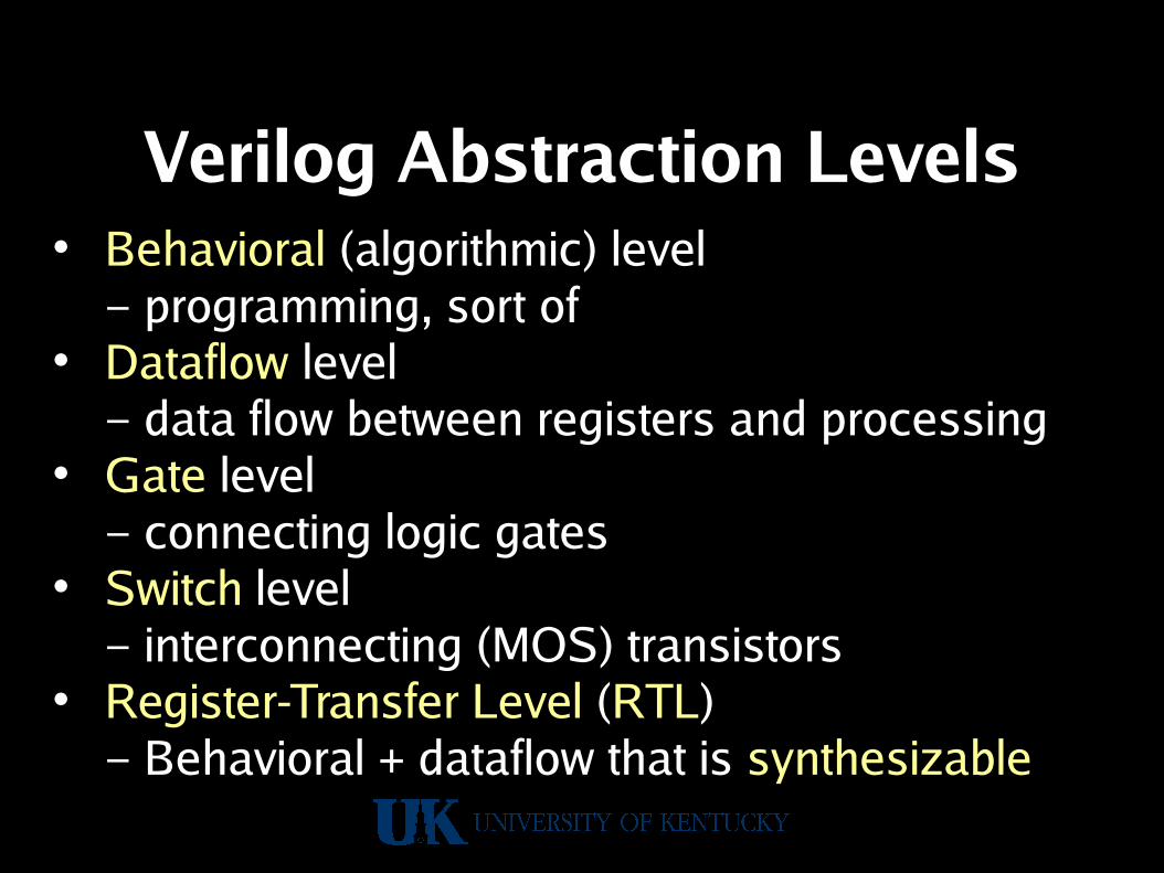
Verilog Abstraction Levels• Behavioral (algorithmic) level
– programming, sort of• Dataflow level
– data flow between registers and processing• Gate level
– connecting logic gates• Switch level
– interconnecting (MOS) transistors• Register-Transfer Level (RTL)
– Behavioral + dataflow that is synthesizable

Hierarchical Modeling
• Top down
• Bottom up

4-bit Ripple Carry Counter

Ripple Counter Hierarchy

T-Filp-Flop

D-Flip-Flop Module• Make a T from a D…
module DFF(q, d, clk, reset); input d, clk, reset; output q; reg q; // q is a registeralways @(posedge reset or
negedge clk) if (reset) q = 1'b0; else q = d;endmodule
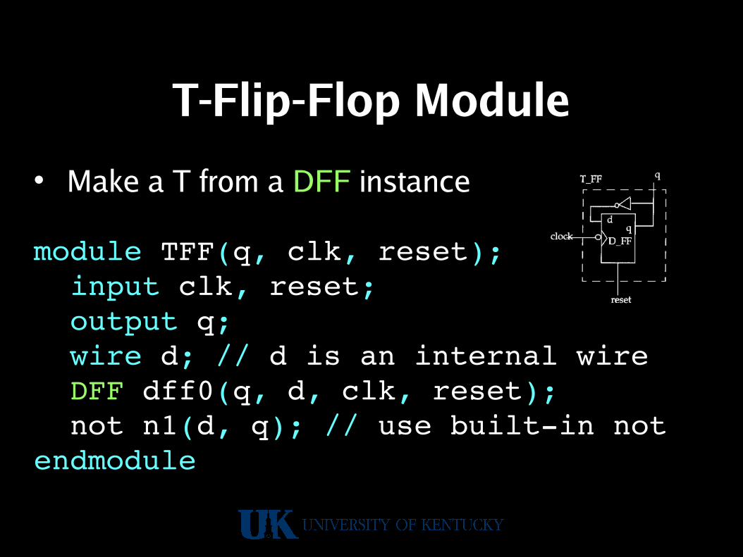
T-Flip-Flop Module
• Make a T from a DFF instance
module TFF(q, clk, reset); input clk, reset; output q; wire d; // d is an internal wire DFF dff0(q, d, clk, reset); not n1(d, q); // use builtin notendmodule

Ripple Counter From 4 TFFs
module ripcount(q, clk, reset); input clk, reset; output [3:0] q; // 4bit output TFF tff0(q[0], clk, reset); TFF tff1(q[1], q[0], reset); TFF tff1(q[2], q[1], reset); TFF tff1(q[3], q[2], reset);endmodule

Test Bench Styles
• Stimulus instantiates design
• Dummy module instantiates both

Example Design & Stimulus
• Stimulus and output waveforms
• Design block

Ripple Counter Stimulusmodule stimulus; reg clk; reg reset; wire[3:0] q; ripcount r1(q, clk, reset); initial clk = 1'b0; always #5 clk = ~clk; // flip clk every 5 ticks initial // drive the reset signal sequence begin reset = 1'b1; #15 reset = 1'b0; #180 reset = 1'b1; #10 reset = 1'b0; #20 $stop; // end simulation end initial // output a trace $monitor($time, “ Output q = %d”, q);endmodule
Ripple Counter
• Need a test framework to try it out…– stimulus module instantiates ripcount– Stimulus initializes values, generates clock,
and prints results each time they change• Can run it here:
http://aggregate.org/EE480/ripplecount.html

Verilog
As A Programming Language
(maybe your first parallel programming language)

Verilog Comments
• Both C comment styles are supported:
// to end of this line is ignored
/* to matching close is ignored */

Verilog Names• Similar to C in many ways:
– All keywords are lowercase– Names can use az, AZ, 09, _– Names don't start with 09– Only system task names can start with $– Whitespace generally treated as a separator
• Escaped identifiers start with \ and end withwhitespace… e.g.:\*@#$%&! // is the name *@#$%&!

Verilog Numbers• Precision (in bits) can be explicit:
– Prefix size' specifies size bits precision– Unsized is at least 32 bits (' optional)
• Base defaults to 10, but can be specified:– Hexadecimal (base 16): h or H– Decimal (base 10): d or D– Octal (base 8): o or O– Binary (base 2): b or B
• E.g.: 255 'Hff 8'o377 8'b11111111

Verilog X And Z Values• Used with base 2, 8, or 16 constants• An unknown value is (lowercase): x
– Number of bits in x determined by base– E.g.: 8'b1010xxxx 8'hax
• A high-impedance value is (lowercase): z– Number of bits in z determined by base– E.g.: 8'bzzzzxxxx 8'hzx
• Extending precision pads with: x z 0e.g.: 4'bxx 4'hx ; 4'b1x 4'b001x

Other Value Oddities
• In numbers:– ? can be used in place of z– _ is ignored (but can't start a number)– E.g.: 8'h2_? 8'b0010zzzz
• Negative numbers:– Always treated as 2's complement– Sign before precision: 8'1 not 8'1

Strength Levels
Strength level Type Degree
supply Driving strongest
strong Driving
pull Driving
large Storage
weak Driving
medium Storage
small Storage
highz High Impedance weakest

Verilog Wires (Nets)• Wires represent potential connections
between hardware elements;signals that are continuously driven
• Keyword: wire tri wand tri0 tri1• Default value: z (or given default 0 or 1)• Can specify width
wire myoutput; // a wiretri [31:0] mybus; // tristate buswand myand; // a wiredAND

Verilog Registers
• Registers represent data storage elements…like variables (not edge-triggered, clocked)
• Retain (unsigned) value until next assignment• Keyword: reg trireg• Default value: x• Can specify width (default at least 32):
reg [15:0] r; // r is a 16bit reg

Verilog Integers
• Integers are basically signed registers• Keyword: integer• Can specify width (default at least 32)• Two equivalent declarations:
integer [15:0] r;
reg signed [15:0] r;

Verilog Reals
• Reals are floating-point values– Can use decimal: 3.14– Can use scientific notation: 314e2
• Keyword: real• Default value: 0• Value is rounded when you need an integer
real r;
Verilog Times
• Times hold values of (simulated) time• Keyword: time• Precision is at least 64 bits• $time system variable gives the current time
time when_started;initial when_started = $time;
Verilog Vectors• A vector specifies multiple-bit width• Applies to reg integer wire• Specifies range and order:[msb_index : lsb_index]
• Can select a bit or a subset of bits
wire [31:0] mybus;reg [0:31] reversed;mybus[15:0] // not mybus[0:15]reversed[16] // just bit 16

Verilog Variable Vector Selectreg [255:0] data1; // little endianreg [0:255] data2; // big endianreg [7:0] byte;
// variable part select, fixed 8bit widthbyte = data1[31:8]; // data1[31:24]byte = data1[24+:8]; // data1[31:24]byte = data2[31:8]; // data1[24:31]byte = data2[24+:8]; // data1[24:31]
// start bit pos can be a variable (but not width)for (j=0; j<=31; j=j+1) byte = data1[(j*8)+:8]; // [7:0], [15:8], …
// initialize only part of a vectordata1[(bytenum*8)+:8] = 8'b0;

Verilog Arrays• An array specifies multi-dimensional collections • Applies to all data types• Specifies range and order:[start_index : end_index]
• Cannot slice, can only select an element• Syntactically declared after identifier,
but any vector subscripting comes last in use
wire [31:0] mybusses [0:4];mybusses[2][15:0] // bus 2, 16 lsbs
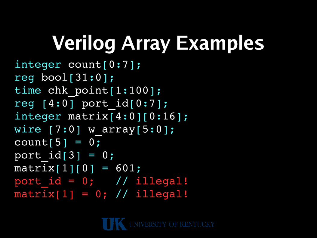
Verilog Array Examplesinteger count[0:7];reg bool[31:0];time chk_point[1:100];reg [4:0] port_id[0:7];integer matrix[4:0][0:16];wire [7:0] w_array[5:0];count[5] = 0;port_id[3] = 0;matrix[1][0] = 601;port_id = 0; // illegal!matrix[1] = 0; // illegal!

Verilog Memories• RAM, ROM, and register files are all basically
modeled as arrays of reg(synthesis is complicated using RAM blocks...)
• Word size for a memory is vector size,number of elements is array size
• Selecting an array element is basically adecoder/mux structure...
// memory holding 65536 bytesreg [7:0] myram[0:'hffff];

Verilog Strings• Strings look like they do in C:
– Surrounded by double-quotes– Escapes: \t \n \” \\ \oct %%– E.g.: ”Hello, World!\012”
• Mostly used for arguments to system tasks• Also can be reg vector initializers filling 8
bits/char from least to most significant
Reg [32*8:1] mystring;mystring = “Hello, World!\n”
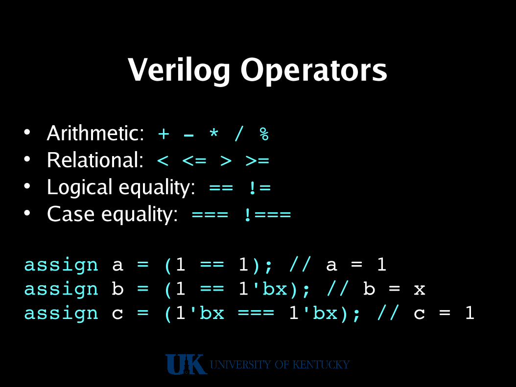
Verilog Operators
• Arithmetic: + * / %• Relational: < <= > >=• Logical equality: == !=• Case equality: === !===
assign a = (1 == 1); // a = 1assign b = (1 == 1'bx); // b = xassign c = (1'bx === 1'bx); // c = 1

Verilog Operators
• Logical: ! && ||• Bitwise: ~ & | ^ ~^ (xnor)• Unary reduction: & ~& | ~| ^ ~^• Shift: >> << (always 0 filled)
assign a = (& 3'b010); // a = 0assign b = (& 3'bz11); // b = xassign c = (3'b110 >> 1); // c = 3

Verilog Operators
• Trinary conditional: ? :• Concatenation: { }• Replication: { { }}
assign a = (1 ? 1'bx : 0); // a = xassign b = {1'1 , 1'0}; // b = 'b10assign c = {2{a,b}}; // c = {a,b,a,b}

Verilog Gate Level
• Built-in: and nand nor or xor xnor– 1st argument is output, then inputs
• Built-in: buf not (drivers)– Any number of output arguments,
then last is the only input– Any z input becomes an x output
and a(out1, in1, in2);buf b(out2, out3, out4, in3);

Gate Level 1-of-4 Mux
module mux1of4(Z,D0,D1,D2,D3,S0,S1);output Z;input D0,D1,D2,D3,S0,S1;not(S0bar,S0),(S1bar,S1);and(T0,D0,S0bar,S1bar), (T1,D1,S0bar,S1), (T2,D2,S0,S1bar), (T3,D3,S0,S1);// should be or, not noror(Z,T0,T1,T2,T3);endmodule

Gate-Level 1-of-4 Mux Example
• tryit only tries one input value• Can run it here:
http://aggregate.org/EE480/mux1of4.html

Verilog Data Flow Modeling
• Uses continuous assignment: assign– Lval: a net, part of a net, or concatenation– Rval is re-evaluated when anything changes
wire[7:0] a, b, c;wire[15:0] big;assign {b, c} = big;assign a=b&c;

Verilog Delay Modeling• Delay between rval change and lval update• Specified in units of time
– Delay in individual assign #delay– Property of a wire #delay
• Changes faster than delay are skipped
wire #5 [7:0] a;wire [7:0] b, c;assign #2 b=c; // delayed 2assign a=c; // delayed 5

Verilog Behavioral Modeling
• Procedural blocks:– All activate at time 0– All execute concurrently– initial blocks execute only at time 0– always blocks execute repetitively, as
specified, e.g.: always@(posedge clk)• Mostly about changing reg values• begin and end can group statements

Always Procedural Timing• always( timing_control )
– An or of identifiers– posedge of an identifier (0→1)– negedge of an identifier (1→0)– # time delay expression (make a waveform)
reg clk;always @(posedge clk) begin ... endalways #5 clk = ~clk;

Procedural Assignments
• Usable in initial or always blocks• Lval must be a reg integer …• Two different assignment operators:
– For a wire: =– For a flip-flop: <=
• Wire assignments can be instantaneous,but flip-flops distinguish before and after state

Procedural Assignments
always @(A or B) // infer wirebegin B=A; C=B;end
Always @(posedge CLK) // flipflopbegin B<=A; C<=B; D<=C;end // clock skew! (may be ok?)

Conditional Statements
• if (expr) statif (expr) stat else stat
• case (expr) cases endcaseA case is: values : statsCan have a: default: stats
• For grouping: begin ... end

Looping Statements
• while (expr) statJust like C
• for (expr ; expr ; expr) statNote: no ++ operator, so ++i is i=i+1if (expr) stat else stat
• repeat (expr) statNot like C – repeat stat expr times
• forever stat

A Big Example: A Multiplier

MultiplierStateMachineFlowchart
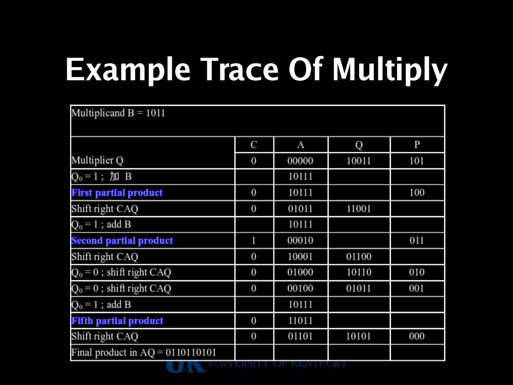
Example Trace Of Multiply
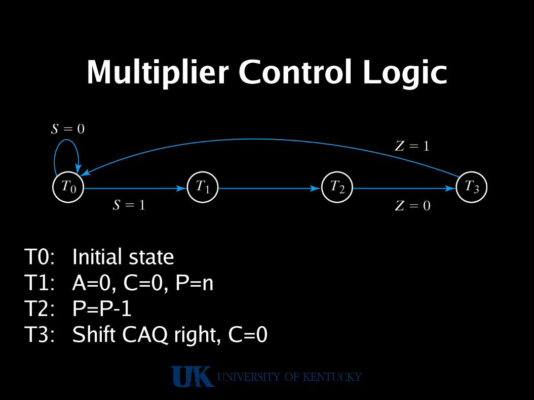
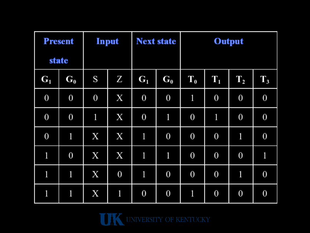
Multiplier Control Logic
T0: Initial stateT1: A=0, C=0, P=nT2: P=P-1T3: Shift CAQ right, C=0

Multiplier Control Block
L is the signal that latches the add result in stateT2 when Q0 is a 1.

Assign State Numbers

Control Logic Diagram

Control Logic Diagram
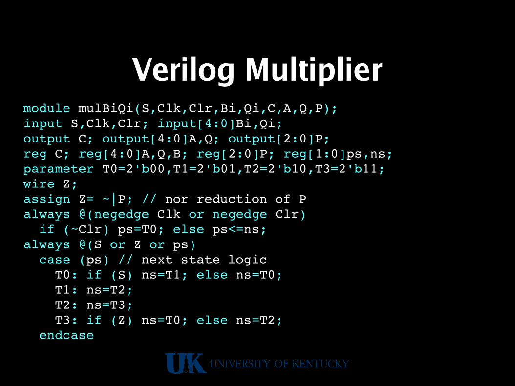
Verilog Multipliermodule mulBiQi(S,Clk,Clr,Bi,Qi,C,A,Q,P);input S,Clk,Clr; input[4:0]Bi,Qi;output C; output[4:0]A,Q; output[2:0]P;reg C; reg[4:0]A,Q,B; reg[2:0]P; reg[1:0]ps,ns;parameter T0=2'b00,T1=2'b01,T2=2'b10,T3=2'b11;wire Z;assign Z= ~|P; // nor reduction of Palways @(negedge Clk or negedge Clr) if (~Clr) ps=T0; else ps<=ns;always @(S or Z or ps) case (ps) // next state logic T0: if (S) ns=T1; else ns=T0; T1: ns=T2; T2: ns=T3; T3: if (Z) ns=T0; else ns=T2; endcase

Verilog Multiplier (continued)
always @(negedge Clk) case (ps) // next state logic T0: B<=Bi; // get multiplicand T1: begin // get multiplier, counter to 5 (bits) A <= 5'b00000; C <= 1'b0; P<=3'd5; Q<=Qi; end T2: begin // do add (verilog builds the adder!) P<=P3'b001; if (Q[0]) {C,A}<=A+B; end T3: begin // shifts C<=1'b0; A<={C,A[4:1]}; A<={A[0],Q[4:1]}; end endcaseendmodule

Verilog Multiplier Test Bench
module test_mulBiQi;reg S,Clk,Clr; reg[4:0]Bi,Qi;wire C; wire[4:0]A,Q; wire[2:0]P;mulBiQi mp(S,Clk,Clr,Bi,Qi,C,A,Q,P);initial begin S=0; Clk=0; Clr=0; #5 S=1; Clr=1; Bi=5'b10111; Qi=5'b10011; #15 S=0; endinitial begin repeat (26) #5 Clk = ~Clk; endalways @(negedge Clk) $strobe(“C=%b A=%b Q=%b P=%b time=%0d”,C,A,Q,P,$time);endmodule

Multiplier Example
• Can run it here:http://aggregate.org/EE480/multiplier.html
• But that’s rather convoluted…So how about the multiplier from EE380?

EE380 Multiplier Example
module mul(ready, c, a, b, reset, clk);
parameter BITS = 32;input [BITS1:0] a, b;input reset, clk;output reg [BITS*21:0] c;output reg ready;reg [BITS1:0] d;reg [BITS1:0] state;reg [BITS:0] sum;
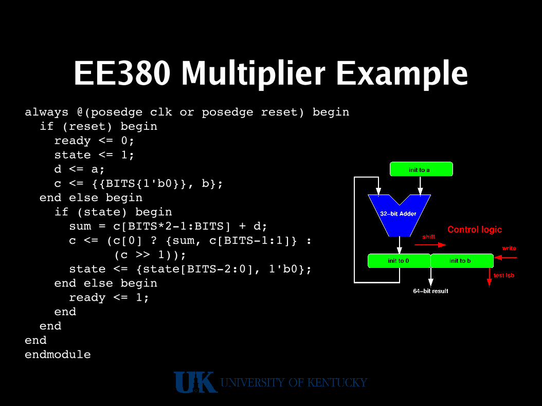
EE380 Multiplier Examplealways @(posedge clk or posedge reset) begin if (reset) begin ready <= 0; state <= 1; d <= a; c <= {{BITS{1'b0}}, b}; end else begin if (state) begin sum = c[BITS*21:BITS] + d; c <= (c[0] ? {sum, c[BITS1:1]} : (c >> 1)); state <= {state[BITS2:0], 1'b0}; end else begin ready <= 1; end endendendmodule

EE380 Multiplier Examplemodule tryit;reg [7:0] a, b;wire [15:0] c;wire rdy;reg reset, clk;
mul #(8) mymul(rdy, c, a, b, reset, clk);initial begin A = 6; b = 7; Clk = 0; reset = 0; #1 reset = 1; #1 reset = 0; repeat (20) begin #1 clk = ~clk; #1 $display(a, " * ", b, " = ", c, " done=", rdy); endendendmodule

EE380 Multiplier Example
• Can run it here:http://aggregate.org/EE480/multiplier.html
• Notice that we only bother with 8 bits…using the parameter to restrict the 32-bit design

Verilog Multiplier Test Bench
module test_mulBiQi;reg S,Clk,Clr; reg[4:0]Bi,Qi;wire C; wire[4:0]A,Q; wire[2:0]P;mulBiQi mp(S,Clk,Clr,Bi,Qi,C,A,Q,P);initial begin S=0; Clk=0; Clr=0; #5 S=1; Clr=1; Bi=5'b10111; Qi=5'b10011; #15 S=0; endinitial begin repeat (26) #5 Clk = ~Clk; endalways @(negedge Clk) $strobe(“C=%b A=%b Q=%b P=%b time=%0d”,C,A,Q,P,$time);endmodule