Embed Size (px)
Citation preview
An Introduction to Petroleum Fuel Facilities: Pipelines and Ground Fueling Facilities Course No: P03-002
Credit: 3 PDH
J. Paul Guyer, P.E., R.A., Fellow ASCE, Fellow AEI
Continuing Education and Development, Inc. 9 Greyridge Farm Court Stony Point, NY 10980 P: (877) 322-5800 F: (877) 322-4774 [email protected]

© J. Paul Guyer 2014 1
J. Paul Guyer, P.E., R.A. Paul Guyer is a registered civil engineer, mechanical engineer, fire protection engineer and architect with 35 years of experience designing buildings and related infrastructure. For an additional 9 years he was a principal staff advisor to the California Legislature on capital outlay and infrastructure issues. He is a graduate of Stanford University and has held numerous national, state and local offices with the American Society of Civil Engineers, Architectural Engineering Institute and National Society of Professional Engineers.
An Introduction to Petroleum Fuel Facilities: Pipelines and Ground Fueling Facilities
© J. Paul Guyer 2014 2
CONTENTS
1. INTERTERMINAL AND INSTALLATION PIPELINES 2. GROUND PRODUCTS FUELING FACILITIES (This publication is adapted from the Unified Facilities Criteria of the United States government which are in the public domain, have been authorized for unlimited distribution, and are not copyrighted.)

© J. Paul Guyer 2014 3
1. INTERTERMINAL AND INSTALLATION PIPELINES 1.1 INTRODUCTION. This discussion provides guidance for the design of pipelines.
Pipelines are typically either interterminal pipelines which are cross country and connect
installations, or installation pipelines which connect petroleum-oil-lubricants (POL)
facilities within an installation. The primary differences are that interterminal pipelines
cross public and private properties, streets, highways, railroads, and utility rights-of-way,
whereas installation pipelines do not. Interterminal pipelines may be dedicated lines
connecting two or more facilities or privately owned common carrier lines serving several
shippers. In some cases, the shipping facility may consist of a relatively short spur which
delivers the fuel to the suction side of a pumping station which is part of the main line of
a larger pipeline system. Pipeline receiving and dispensing facilities are normally part of
a bulk fuel storage facility.
1.2 GENERAL REQUIREMENTS. Do not start the design of any fueling system without
first becoming completely familiar with general design requirements.
1.3 DESIGN REQUIREMENTS.
1.3.1 FUEL SEGREGATION. Clean products, such as diesel fuel and distillate-type
burner fuels, may be shipped in the same system without segregation. Batches are
usually pumped product to product, but they may be separated by fresh or suitably treated
water. Separate piping systems are required for residual fuels. For many projects, provide
a dedicated pipeline for aviation turbine fuels.
1.3.2 APPLICABLE REGULATIONS. Interterminal and installation pipelines shall be
designed as described below. Where federal, state, or local regulations are more
restrictive than the requirements indicated, the more restrictive requirements shall apply.
1.3.2.1 INSTALLATION PIPELINES. All installation pipelines shall be designed in
accordance with ANSI/ASME B31.3.
© J. Paul Guyer 2014 4
1.3.2.2 INTERTERMINAL PIPELINES. The U.S. Department of Transportation regulates
the design, construction and operation of interterminal pipelines for liquid petroleum.
Intrastate interterminal pipelines shall be designed in accordance with ANSI/ASME B31.4.
Interstate interterminal pipelines, shall be designed in accordance with the requirements
of 49 CFR Part 195.
1.3.3 SAMPLING. Provide a means for taking samples of the products shipped.
1.3.4 PIGGING. Pipelines shall be smart piggable including long radius elbows and
barred fittings unless otherwise directed by The Owner.
1.3.5 SURGE SUPPRESSION. Provide surge suppressors for hydraulic shock when
required.
1.4 PIPING SYSTEMS. Refer to appropriate references for information regarding piping
systems.
1.5 EQUIPMENT. Equip all pipelines with meters and basket strainers, and provide the
capability to install a proving meter.
1.5.1 METERS. 1.5.1.1 METERS – POSITIVE DISPLACEMENT. Use flange-connected, cast steel
bodied positive displacement meters of the desired pressure and flow rating to meet
applicable service requirements. Ensure that meter has case drain and register. Provide
meter with temperature compensation and adjustable calibration where there is custody
transfer. Ensure meter accessories are compatible with either the mechanical or
electronic support equipment selected. Consult the Owner for requirements for the meter
to communicate to a remote location or equipment.
© J. Paul Guyer 2014 5
1.5.1.2 METERS – TURBINE. Use flange-connected steel bodied turbine meters of the
desired pressure and flow rating to meet applicable service requirements. Provide a flow
straightener before turbine meters or provide a straight length of pipe at a minimum of ten
pipe diameters upstream and five pipe diameters downstream of all turbine meters, or as
required by manufacturer. Ensure meter has case drain and register. Provide \1\ meter
with temperature compensation and adjustable calibration /1/ where there is custody
transfer. Ensure all supporting equipment for meter is compatible with the turbine meter
selected. Consult the Owner for requirements for the meter to communicate to a remote
location or equipment. Consider the use of a card-operated or key-operated data
acquisition system. Cards or keys, as appropriate, are coded to identify the receiver of
the fuel and to allow access to the fuel. The quantities taken are transmitted to a data-
receiving device by electronic pulse transmitters mounted on each meter, and each
transaction is automatically recorded.
1.5.2 MANUAL VALVES. 1.5.2.1 MATERIALS OF CONSTRUCTION. Require valves to have carbon steel bodies
and bonnets. Do not allow valves with aluminum, cast iron, or bronze materials. Use only
API fire-safe valves.
1.5.2.2 ISOLATION VALVE TYPES.
a) Double Block and Bleed Isolation Valves:
• Use these for separation of product services, on tank shell connections, when
piping goes above or below ground, between pier and tank storage, and other
locations critical to pressure-testing of piping.
• Plug Valves (Double Block and Bleed): Use lockable, double-seated, tapered lift,
plug type valves with an automatic body bleed between the seats (double block
and bleed) in critical applications such as separation of product services, on each
© J. Paul Guyer 2014 6
line at the shore end, when piping goes above or below ground, between pier and
tank storage, and other locations critical to pressure-testing of piping. Valves shall
be designed so that if the synthetic seating material is burned out in a fire, a metal-
to-metal seat will remain to affect closure and comply with API Std 607. Lubricated
plug valves are not allowed. Include integral body cavity thermal relief valve.
• Ball Valves (Double Block and Bleed): Use double-seated, trunion mounted,
lockable, ball type valves with a body bleed between the seats (double block and
bleed). These will be very rarely used but are acceptable as an alternative to
double block and bleed plug valves in applications where the valve is operated
very infrequently. An example is isolation valves in the middle of piers that are only
closed to perform pressure testing of piping. Valves shall be designed so that if the
synthetic seating material is burned out in a fire, a metal-to-metal seat will remain
to affect closure and comply with API Std 607. Include integral body cavity thermal
relief valve.
• Gate Valves: Use double-seated, lockable, gate type valves with a body bleed
between the seats (double block and bleed). These will be very rarely used but are
acceptable as an alternative to double block and bleed plug valves and double
block and bleed ball valves only when other double block and bleed valves will not
physically fit. Valves shall be designed so that if the synthetic seating material is
burned out in a fire, a metal-to-metal seat will remain to affect closure and comply
with API Std 607. Single seated gate valves are not allowed. Include integral body
cavity thermal relief valve.
b) Quick Opening/Frequent Opening Isolation Valves.
• Use these for less critical applications where double block and bleed shutoff is not
required.

© J. Paul Guyer 2014 7
• Ball Valves: Ball type valves may be used as valves for quick or frequent opening
applications when a double block and bleed valve is not required. Ball valves shall
be designed so that if the synthetic seating material is burned out in a fire, a metal-
to-metal seat will remain to affect closure and comply with API Std 607. Use Teflon
or Viton synthetic seals or seating material. Use full port ball valves with exact
same diameter of the pipe within ten pipe diameters upstream and/or five pipe
diameters downstream of a flow or pressure control valve, or a flow-sensing device
such as a venturi. Valves should comply with API Std 608.
c) Butterfly Valves: Butterfly valves are not allowed.
d) Use full port valves with exact same diameter of the pipe when line pigging is required.
1.5.2.3 ISOLATION VALVE OPERATORS. Provide manually operated valves not
specified for remote, automatic, or emergency operation. Use geared operators for ball
and double block and bleed valves larger than 6 inches (150 mm). Double block and
bleed gate, ball, and double block and bleed valves specified for remote, automatic, or
emergency service may have electric motor operators with suitable torque limiting
controls if approved by The Owner. For remote valves, consider using solar battery packs
to reduce cost of routing power for the motor operators. Provide locking tabs on isolation
valves to allow padlocks to be used to lock out valves during maintenance. Provide chain
operators on valves which are located 72 inches (1800 mm) or higher above grade.
1.5.2.4 ISOLATION VALVE LOCATIONS. Provide valves in product piping systems to
control flow and to permit isolation of equipment for maintenance or repair. Provide
additional valves at required locations necessary to conduct a valid hydrostatic test.
Provide manually operated valves, except where motor operators are specifically
authorized by applicable standard drawings or technical specifications. Use double block
and bleed type isolation valves for separation of product services, on tank shell
connections (ASTs over 12,000 gallons (45,800 L) only), when piping goes above or
below ground, between pier and tank storage, and other locations critical to periodic

© J. Paul Guyer 2014 8
pressure-testing of piping. Quick opening/frequent opening type isolation valves may be
used for less critical applications where double block and bleed shutoff is not required.
Before adding isolation valves, evaluate piping system and make modifications to prevent
pressure buildup caused by thermal expansion. As a minimum requirement, provide
isolation valves at the following locations:
a) Provide a double block and bleed isolation valve on each branch line at the point of
connection to the main product pipeline or header.
b) Provide a double block and bleed isolation valve on the product pipeline or header just
before the line leaves a pumping station.
c) Provide a double block and bleed isolation valve at the inlet and outlet connection of
each line strainer, filter/separator, meter, diaphragm control valve, thermal relief valve,
and other equipment that requires periodic servicing. One inlet and one outlet double
block and bleed isolation valve may be used to isolate more than one piece of adjacent
equipment which are connected in series.
d) Provide a double block and bleed isolation valve on the upstream and downstream
side of each line blind at connections to cross country pipelines.
e) Provide a double block and bleed isolation valve on each main distribution pipeline
immediately downstream of the branch connection to each existing or future operating
storage facility served by the pipeline.
f) Provide a double block and bleed isolation valve at intermediate points of approximately
10 miles (16 km) in cross country distribution pipelines to facilitate isolation of a section
of the line for maintenance and repair.
g) Provide a double block and bleed isolation valve on each side of water crossing
exceeding 100 feet (30 m) in width, and near the shoreline of a submerged sea pipeline.

© J. Paul Guyer 2014 9
h) Provide a double block and bleed isolation valve at critical points where pipes cross
under runways, taxiways, and roadways.
i) For low-point drains and high-point vents.
1.5.2.5 ISOLATION VALVE PITS. Provide fiberglass or concrete pits with a rolling or
hinged cover for all isolation valves installed in non-traffic areas on underground fuel
systems. Design valve pits and valve operators so that the valves can be operated by
personnel, without confined space entry.
1.5.3 OTHER VALVES (EXCEPT DIAPHRAGM CONTROL VALVES). 1.5.3.1 CHECK VALVES. Use check valves to prevent backflow through pumps, branch
lines, meters, or other locations where runback or reverse flow must be avoided. Check
valves may be of the swing disk, globe, dual plate hinged disk, spring-loaded poppet, ball,
or diaphragm-actuated types. Use checks of soft-seated non-slamming type with
renewable seats and disks. Ensure check valves conform to API Spec 6D. Use diaphragm
non-surge check valves with flow control feature on the discharge of all pumps. When
using non-surge check diaphragm control valves on pump discharge, consider the use of
a spring type wafer check before the diaphragm valve to prevent sudden flow reversals
during shutdown from passing back thru the pump before the diaphragm control valve
diaphragm chamber is filled and reacts by closing the valve.
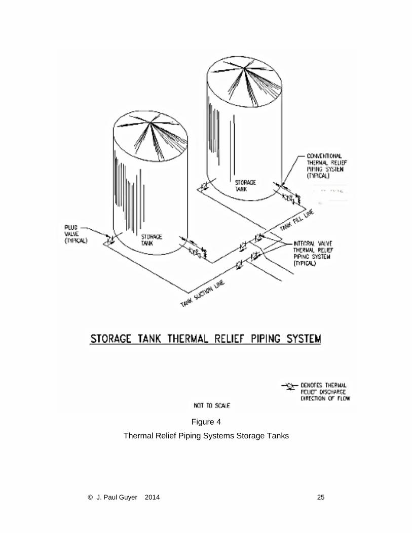
1.5.3.2 THERMAL RELIEF. Provide thermal relief valves around shutoff and check
valves to relieve excessive pressures caused by thermal expansion of liquid trapped
between shutoff points. See figures 1, 2, 3 and 4.
1.5.4 DIAPHRAGM CONTROL VALVES. Hydraulically operated, single-seated, globe
type, diaphragm actuated control valves are used extensively in fueling systems as
control valves. These valves consist of a main valve and a pilot control system. The valve
© J. Paul Guyer 2014 10
is operated by varying the amount of pressure above the diaphragm. Since the chamber
above the diaphragm exposes a greater area of the diaphragm to chamber pressure than
the area of the disc exposed to line pressure, an equal pressure in the chamber and
pipeline results in a greater force being applied to the top of the disc. This forces the disc
against the seat, thus closing the valve. By selecting the proper pilot control system, these
valves can be used in numerous ways to control flow, pressure, and level within fueling
systems. Use extreme care when including these valves on pipelines as they can
significantly contribute to surge potential, if closing time is too short. When properly
adjusted, they can reduce surges.
1.5.4.1 OPEN/CLOSE OPERATION. This is the most basic operation of hydraulically
operated diaphragm control valves. The operation is accomplished by applying pressure
above the diaphragm to close the valve and relieve that pressure to allow line pressure
to open the valve. The pilot trim used to perform this operation is a three-way valve which
can be controlled by a solenoid, hand, pressure, pressure differential, or a float.
1.5.4.2 THROTTLING OPERATION. This is the other main method of controlling the
hydraulically operated diaphragm control valve. In this case, the valve modulates to any
degree of opening, in response to changes in the throttling control. The throttling control
reacts to a pressure, or a pressure differential across the main valve, or pressure
differential across an orifice plate to regulate the position of the disc in the main valve;
provide full port manual isolation valves if they are placed within these limits.
1.5.4.3 CHECK VALVE FUNCTION. This is a unique function of a control valve. In this
case, the main valve outlet pressure is connected to the diaphragm cover. Therefore, if
the downstream outlet pressure exceeds the inlet pressure, which normally holds the
valve open, the valve will close and prevent backflow.
1.5.4.4 REMOTE OPERATIONS. Hydraulically operated diaphragm control valves can
be operated remotely. This is accomplished by installing tubing from the point of pressure
sensing to the valve or by using remote-controlled solenoids within the trim.

© J. Paul Guyer 2014 11
1.5.4.5 MATERIALS OF CONSTRUCTION. Use stainless steel pilots and stainless steel
tubing. Use bodies, bonnets, and covers made of stainless steel, internally plated
(chrome) steel, or internally plated (nickel) nodular iron. Provide Viton or Buna-N
diaphragm and disc ring. Enclose all electrical apparatus according to classification of the
area in which they are installed. Provide a means to wire seal all adjustable pilots. Do not
use aluminum valves.
1.5.4.6 APPLICATIONS. For pipeline systems, use hydraulically operated diaphragm
control valves in the following applications:
a) Rate of flow control.
b) Pressure reduction.
c) Pressure relief.
d) Excess flow shutdown.
1.5.4.7 COMBINATIONS. A combination of these controls is also possible.
1.5.5 STRAINERS. Require a strainer to protect centrifugal pumps, unless it precludes
meeting the net positive suction head of the pump. Whether or not strainers are installed
on the suction side of centrifugal pumps, install a spool piece so that temporary strainers
can be installed during startup of the system. Strainers are required on the suction side
of all pumps, meters, and receipt filtration. Strainers are not required upstream of issue
filter/separators or diaphragm control valves. Also:
a) Use flanged strainers constructed of steel and fitted with removable baskets of fine
Monel metal or stainless steel mesh with large mesh reinforcements.
b) Unless otherwise specified, provide a fine screen mesh as follows:
c) In all cases, ensure the effective screen area is not less than three times the cross
sectional area of the pipe.

© J. Paul Guyer 2014 12
d) Strainers upstream of pump shall be quick opening, single screw type with drain
connection at bottom.
e) Provide pressure gauges on both sides of the strainer and a differential type gauge
across the strainer.
1.5.6 SURGE SUPPRESSORS. Every effort should be made to control hydraulic surge
or shock to acceptable limits by the design of the piping system rather than by the use of
surge suppressors. Where this is not possible or becomes extremely impractical, surge
suppressor(s) may be incorporated. Use the diaphragm or bladder type equipped with a
top-mounted liquid-filled pressure gauge, wafer-style check valve at the bottom, drain
above the check valve, and isolation valve. Provide a needle valve around the check valve
to permit controlled bleed back of the surge suppresser without rebounding. Locate surge
suppressors as close as possible to the point of shutoff that is expected to cause the
shock. Surge suppressors can reduce shock pressure but will not eliminate it entirely. The
preferred solution to hydraulic shock is conservative piping design, use of loops, and
slow-closing valves. Surge suppressors are strictly a last resort solution and require the
approval of The Owner prior to designing into a system.
1.5.7 PIGGING EQUIPMENT. Equip all pipelines with outlets to allow the connection of
pig launchers and receivers. Design the outlets so that they can accommodate internal
nondestructive inspection trains. Provide sufficient curvature of bends in the pipeline to
permit free passage for such equipment. Provide tees with, factory installed internal guide
bars, at all branch connections.
© J. Paul Guyer 2014 13
1.5.8 PUMPS. If multiple pump stations are required to keep pipeline pressure within
safe limits, provide them at appropriate locations.
1.5.9 SAMPLING CONNECTIONS. Provide connections for sampling fuels on each
section of a fuel transfer piping system. Install sampling and testing connections at
receiving points, tank outlets, inlet and outlet sides of filter/separators, fuel dispensing
points, and between isolation valves so that remaining fuel in each portion of a fuel
transfer pipeline can be sampled. Where possible, install sampling connections in vertical
runs. Provide a 1/4-inch (8 mm) diameter sample point with a probe, ball valve, and quick
disconnect with dust cap.
1.5.10 SPECIAL CONSIDERATION FOR AVIATIONTURBINE FUELS. Special
considerations for inbound filtration of aviation turbine fuels apply.
1.6 PRODUCT RECOVERY SYSTEMS. Provide a product recovery system to collect and
store usable aviation turbine fuel that would otherwise become waste from operational or
maintenance activities. Consider a product recovery system for other products.
1.7 CANOPIES.
1.7.1 CANOPIES TO PROTECT FIXED ASSETS FROM EXTREME WEATHER CONDITIONS. Unless otherwise directed by The Owner, provide a canopy to protect
fixed facility assets, operators, and equipment from the extreme weather conditions (I.E.
re-occurring/sustained extreme icing/snow or desert like conditions. Fixed facilities and
equipment include but are not limited to: pump pads, filtration pads, meter pads, isolation
valve pads, tank truck and tank-car off-loading and loading equipment pads, control
panels, electrical panels, and motor control centers (MCCs).
1.7.2 CANOPIES TO REDUCE STORMWATER. Do not provide a canopy to preclude
rain from reaching the containment area unless it is required by federal, state, or local
regulations; or it is economically justified by reducing the size of the concrete remote spill

© J. Paul Guyer 2014 14
containment or spill treatment system; or if directed by The Owner. At a canopy over a
tank truck or tank car loading and off-loading containment area, ensure that the underside
of the canopy is high enough to provide operator head room when walking on top of the
truck or car.
1.8 SPECIAL CALCULATIONS. Calculate pipeline filling/venting times and
draining/stripping times. The larger and the longer the pipeline, the greater the volume of
fuel required to fill the line and, therefore, the greater the volume of air required to be
vented. Undersized vent lines will delay filling the lines and delay changeover of products
in multiproduct lines. Size vent lines to allow filling of the line at not more than four times
the design transit time of the line. Where applicable, connect vent lines to system drain
lines to avoid spills to the environment. Check vent line air velocity, which must not exceed
the allowable air velocity to avoid electrostatic buildup, in accordance with API RP 2003.
Vent rate must be not less than the lowest allowable pumping rate from ship or shore.
Vent rate must be less than the design transit velocity to minimize hydraulic shock.
© J. Paul Guyer 2014 15
2. GROUND PRODUCTS FUELING FACILITIES. 2.1 INTRODUCTION. This discussion provides guidance for the design of ground
products (gasoline, diesel) fueling facilities and covers vehicle motive fuel filling stations
and tactical refueler truck loading facilities. Private vehicle filling stations, such as
exchange service stations, are not included.
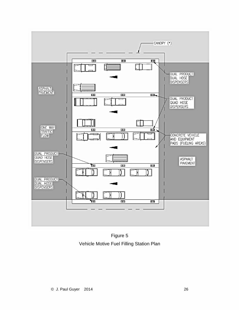
2.1.1 TYPES OF FACILITIES. The following three types of filling stations may be required (see figures 5, 6 and 7):
a) A filling station for dispensing motive fuel gasoline and diesel into government
(commercial type) sedans, vans, and small trucks. See figure 5.
b) A filling station for dispensing motive fuel gasoline and diesel into vehicles. See figures
5 and 6.
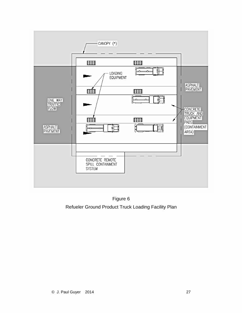
c) A truck loading facility for loading gasoline and diesel into refueler vehicles. See figures
6 and 7.
2.2 GENERAL REQUIREMENTS. Do not start the design of any fueling system without
first becoming completely familiar with general design requirements.
2.3 DESIGN REQUIREMENTS. 2.3.1 FUEL SEGREGATION. Provide separate receiving, storage and distribution
systems for each grade or type of fuel. Except as otherwise approved by The Owner,
prevent misfueling (transferring a type of fuel other than the type intended) by using
different size piping, valves, adaptors, nozzles, etc. Use color coding in accordance with
API RP 1637. Outside the U.S., use host nation standard if it is different than API RP
1637. Use API RP 1637 if no other standard is in effect.
2.3.2 FACILITY SIZE. In each filling station, provide one commercial-type dispensing unit
which displays volume only for each 100 vehicles assigned to the activity. The total

© J. Paul Guyer 2014 16
amount of storage capacity in each station should be approximately twice the capacity of
all vehicle fuel tanks, by grade or type of fuel, assigned to the activity. Minimum storage
capacity for any grade or type of fuel is 5,000 gallons (19,000 L) unless approved by The
Owner.
2.3.3 FACILITY CONFIGURATIONS. In general, for control and safety, separate the
three types of filling stations. For a relatively small installation or one on which there is a
limited amount of activity expected at one time, it may not be practical to provide totally
separate facilities. In those cases, separate the functions as much as possible to minimize
mixing traffic of commercial-type vehicles from tactical vehicles and, more importantly,
from mixing tactical refuelers which are being loaded with relatively large quantities of fuel
from other vehicles which are being fueled for their own engine (motive fuel). Filling
stations must be configured to comply with all NFPA 30A siting and storage requirements.
2.3.4 SHELTERS. For staffed facilities, provide a shelter for personnel, records, and
tools.
2.3.5 CONCRETE FUELING AREA – FILLING STATIONS. Create a fueling area
constructed of concrete by surrounding fueling islands with a concrete slab graded at a
minimum of 1 percent away from the islands.
2.3.6 CONCRETE FUELING AREA –REFUELER TRUCK LOADING FACILITIES. Provide concrete spill containment areas and concrete remote spill containment systems.
2.3.7 CANOPIES. 2.3.7.1 CANOPIES TO PROTECT FIXED ASSETS. Provide a canopy for protection from
the elements of fixed facility assets and equipment as directed by The Owner, for all
pumps, meters, strainers, filters, control panels, electrical panels, and motor control
centers (MCCs).
© J. Paul Guyer 2014 17
2.3.7.2 CANOPIES TO REDUCE STORMWATER AT REFUELER TRUCK LOADING FACILITIES. Do not provide a canopy to preclude rain from reaching the containment
area unless it is required by federal, state, or local regulations; or it is economically
justified by reducing the size of the concrete remote spill containment or spill treatment
system; or if directed by The Owner. Ensure that the underside of the canopy is high
enough to provide operator head room when walking on top of the truck.
2.3.7.3 CANOPIES TO REDUCE STORMWATER OF FILLING STATIONS. Do not
provide a canopy to preclude rain from reaching the concrete fueling area unless it is
required by federal, state, or local regulations; or a concrete remote spill containment or
treatment system is required by federal, state, or local regulations and it is economically
justified by reducing the size of the remote spill containment or spill treatment system; or
if directed by The Owner.
2.3.8 REGULATIONS. Design must comply with NFPA 30, NFPA 30A, and API RP 1615.
2.3.9 BOTTOM LOADING. The bottom loading of refuelers is required if the refuelers are
equipped for it. However, there are refuelers which are not equipped for bottom loading
and which will be in inventory for several years. Therefore, consult The Owner before
providing top loading at tactical refueler fillstands.
2.3.10 TRUCK OFFLOAD AND LOADING FACILITIES. Design of service station truck
offload and loading facilities must comply with NFPA 30, NFPA 30A and 40 CFR Part
112. Also, do not locate truck offload or tactical refueler loading facilities closer than 25
feet (7.6 m) from above ground tanks, buildings, roads, overhead power lines, pad-
mounted transformers, and property lines. With the exception of overhead power lines,
these minimum separation distances may be permitted to be reduced to 15 feet (4.6 m)
for Class II or III liquids.
© J. Paul Guyer 2014 18
2.4 STORAGE TANKS. For ground products fueling facilities underground, horizontal
tanks are preferred. Follow federal, state, and local regulations when determining use of
AST or UST.
2.5 PIPING SYSTEMS. 2.5.1 PIPING SYSTEM – TACTICAL REFUELER FACILITIES. For systems serving
tactical refueler fillstands see appropriate references.
2.5.2 ABOVEGROUND PIPING SYSTEM – FILLING STATIONS. Follow state or local
regulations when they exceed these requirements. When they do not exceed them,
provide as described with the following exceptions:
a) Piping 4 inches (100 mm) and larger shall be buttwelded or socket welded. Use flange
connections for joining pipe to equipment.
b) Piping smaller than 4 inches (100 mm) may be buttwelded, or socket welded. Use
flange connections, or socket weld connections with unions for joining pipe to equipment.
Threaded end connections may be used only where buttwelded or socket welded
connections cannot physically be provided.
c) Branch outlet fittings do not have to be designed to be radiographed.
2.6 EQUIPMENT DESCRIPTIONS. 2.6.1 FILLING STATIONS. 2.6.1.1 FUEL DISPENSERS. Use a commercially available dispenser with a self-
contained electric motor and pumping unit or a remote pumping type where the pump and
motor are located in the storage tank. If an in-tank type of pump is used, ensure that it is
equipped with a reduced start volume as a leak check. Provide a meter for each
dispenser. Dispenser flow rates are typically a maximum of 10 gpm (0.6 L/s); follow state
and local regulations for actual maximum. Designer shall check with state and local

© J. Paul Guyer 2014 19
regulations for limitations on dispenser flowrates. Dispensing system will include
management control system, printers, computers, and microprocessors. Equip fuel
dispensers with an inline filtration system capable of sediment removal to 10 mg/L or less.
Add emergency break-away hose connections at each fuel dispenser in accordance with
NFPA 30A. Where liquid is supplied to the dispenser under pressure, provide an
emergency shutoff valve, incorporating a fusible link, in the supply line at the base of each
dispenser as required by NFPA 30A. Equip dispensing islands with impervious spill
containment pans under the dispensers.
2.6.1.2 CARD AND KEY LOCKS. Consider the possible economic and operational
advantages of using an electronic card or key system which permits 24-hour unmanned
operation of the facility. These types of systems are comprised of a card/key reader which
is located near the service pump. The reader is activated by a card or key and
accumulates issues and customer data which is downloaded to a central computer on a
periodic basis.
2.6.2 REFUELER TRUCK LOADING FACILITIES. Equip similar to truck loading facilities
except provide a grounding reel in lieu of the high-level shutoff/ground detecting system.
Verify the type of nozzle required by the user.
2.6.3 VALVES. For systems serving refueler fillstands see the requirements for tank truck
loading facilities. The below requirements apply to filling station only.
2.6.3.1 MATERIALS OF CONSTRUCTION. Require valves to have carbon steel bodies
and bonnets. Do not allow valves with aluminum, cast iron, or bronze materials. Use only
API fire-safe valves.
2.6.3.2 ISOLATION VALVE TYPES.
a) Ball Valves: These are the only approved quick opening/frequent opening isolation
valves. Ball type, lockable, valves designed so that if the synthetic seating material is

© J. Paul Guyer 2014 20
burned out in a fire, a metal-to-metal seat will remain to affect closure and comply with
API Std 607. Use Teflon or Viton synthetic seals or seating material. Valves should
comply with API Std 608.
b) Double Block and Bleed Isolation Valves: Do not provide unless directed by the Owner.
c) Lubricated Plug Valves: Lubricated plug valves are not allowed.
d) Gate Valves: Gate valves are not allowed.
e) Butterfly Valves: Butterfly valves are not allowed.
2.6.3.3 ISOLATION VALVE OPERATORS. Manually operate valves not specified for
remote, automatic, or emergency operation. Use geared operators for ball valves larger
than 6 inches (150 mm). Provide locking tabs on isolation valves to allow padlock to be
used to lock out the valves during maintenance. Provide chain operators on valves which
are located 72 inches (1800 mm) or higher above grade.
2.6.3.4 ISOLATION VALVE LOCATIONS. Provide isolation valves in piping systems to
control flow and to permit isolation of equipment for maintenance or repair, or as
necessary to conduct a valid hydrostatic test. As a minimum requirement, provide
isolation valves at the following locations:
a) Where piping goes underground or comes aboveground and requires periodic pressure
testing.
b) At all subsurface and aboveground piping connections to storage tanks.
c) On the suction side and discharge side of each pumping unit, except the suction side
of vertical centrifugal pumps installed in underground tanks.
d) On the inlet and outlet connection of each line strainer, meter, diaphragm control valve,
and other equipment that requires periodic servicing. One inlet valve and one outlet valve
may be used to isolate more than one piece of adjacent equipment which are connected
in series.
2.6.4 DIAPHRAGM CONTROL VALVES. These valves are not required in filling stations.
© J. Paul Guyer 2014 21
2.6.5 OTHER VALVES. 2.6.5.1 CHECK VALVES. Use check valves to prevent backflow through pumps, branch
lines, meters, or other locations where runback or reverse flow must be avoided. Check
valves may be of the swing disk, globe, dual plate hinged disk, spring-loaded poppet, ball,
or diaphragm-actuated types. Use checks of soft-seated non-slamming type with
renewable seats and disks. Ensure check valves conform to API Spec 6D.
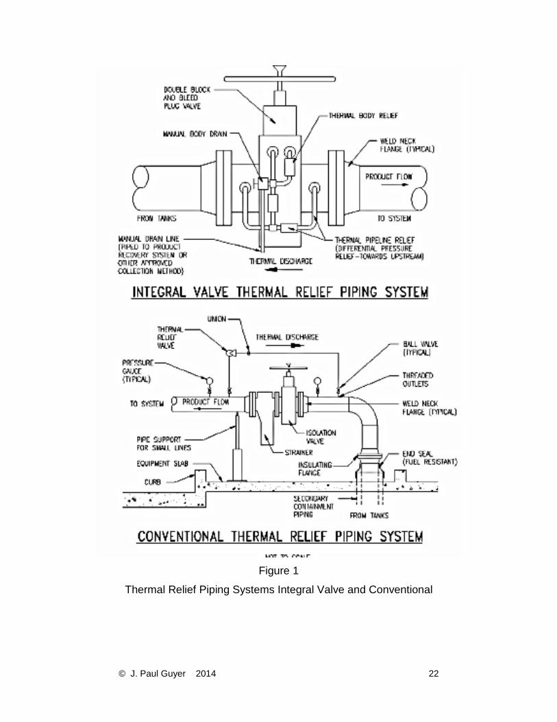
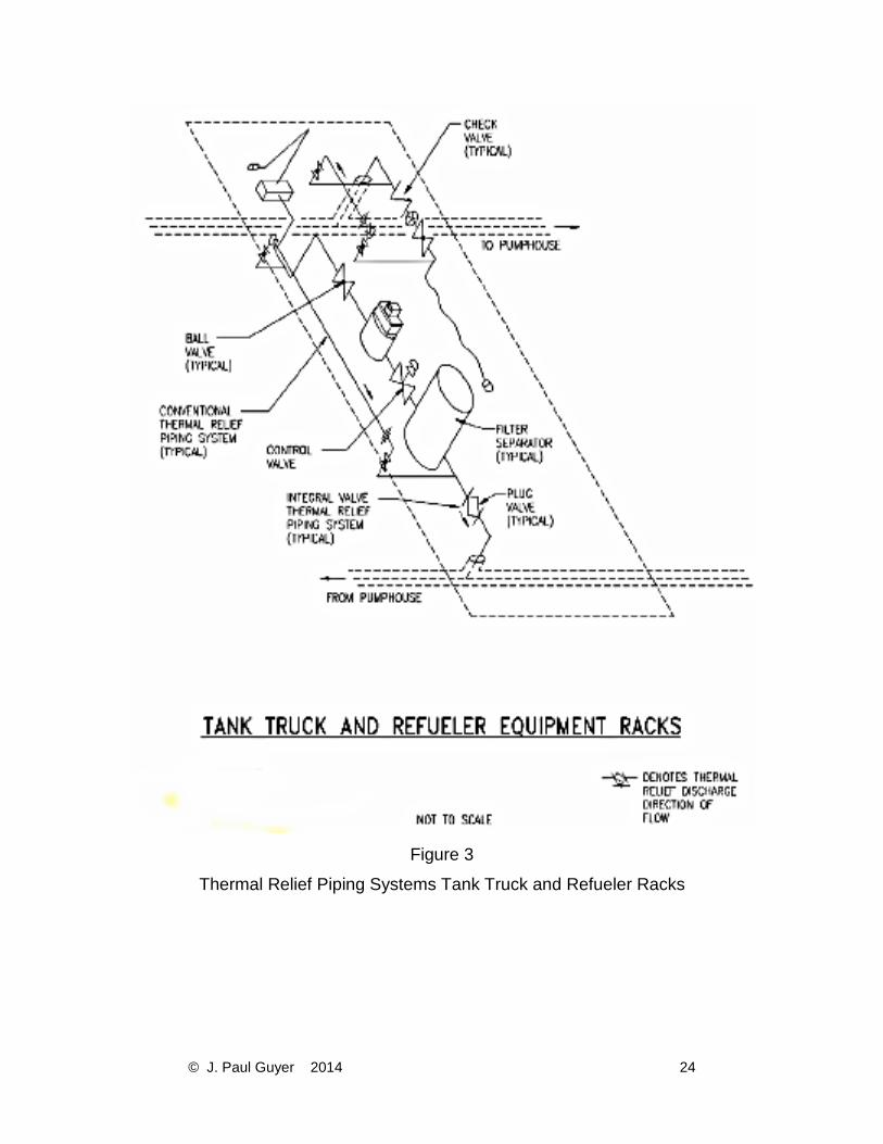
2.6.5.2 THERMAL RELIEF. Provide thermal relief valves around isolation and check
valves to relieve excessive pressures caused by thermal expansion of liquid trapped
between shutoff points. See figures 1, 2, 3 and 4. 2.7 VAPOR RECOVERY. Provide vapor recovery in accordance with guide specifications
unless there are more stringent federal, state, and local codes or regulations. Some
requirements are in 40 CFR Part 60 Subpart XX. If gasoline is being handled, provide, as
a minimum, Stage I vapor recovery and the piping for Stage II. If Stage II is not required
by local or state regulations at time of installation, cap the vapor return pipe at the
dispenser.
© J. Paul Guyer 2014 22
Figure 1
Thermal Relief Piping Systems Integral Valve and Conventional

© J. Paul Guyer 2014 23
Figure 2
Thermal Relief Piping Systems Equipment Pump House or Pads
© J. Paul Guyer 2014 24
Figure 3
Thermal Relief Piping Systems Tank Truck and Refueler Racks
© J. Paul Guyer 2014 25
Figure 4
Thermal Relief Piping Systems Storage Tanks
© J. Paul Guyer 2014 26
Figure 5
Vehicle Motive Fuel Filling Station Plan
© J. Paul Guyer 2014 27
Figure 6
Refueler Ground Product Truck Loading Facility Plan

© J. Paul Guyer 2014 28
Figure 7
Refueler Ground Product Truck Loading Systems