Embed Size (px)
Citation preview

Universitat Karlsruhe (TH)Fakultat fur InformatikInstitut fur Rechnerentwurf und FehlertoleranzLehrstuhl Prof. Dr.-Ing. R. Dillmann
An Interactive Interface for a Service Robot –
Design and Experimental Implementation
Diplomarbeit
Elin Anna Topp
Oktober 2003
Beginn der Arbeit: 01.05.2003Abgabe der Arbeit: 31.10.2003
Referent: Prof. Dr.-Ing. R. DillmannKorreferent: Prof. Dr.-Ing. U. D. HanebeckInstitut fur Rechnerentwurf und Fehlertoleranz, Universitat Karlsruhe
Betreuer: Prof. Dr. H. I. ChristensenCentre for Autonomous Systems, KTH Stockholm


Hiermit erklare ich, die vorliegende Diplomarbeit selbstandig angefertigt zu haben.
Die verwendeten Quellen sind im Text gekennzeichnet und im Literaturverzeichnis
aufgefuhrt.
Karlsruhe/Stockholm, 31. Oktober 2003,
Elin Anna Topp


I
Preface
This master thesis presents the work done between May, 1st and October, 31st 2003.
It was conducted within the group of Professor Henrik I. Christensen at the Centre
for Autonomous Systems (CAS) of the Department of Numerical Analysis and Com-
puting Science (NADA) at the Royal Institute of Technology (KTH) in Stockholm.
I would like to thank first of all my supervisor in Stockholm, Professor Christensen,
as well as Dr. Danica Kragic and Dr. Patric Jensfelt for their help during the work.
Thanks to Professor Rudiger Dillmann at the Institute for Computer design and
Fault Tolerance at the University of Karlsruhe, who made it possible for me to work
on this thesis in Stockholm. Further, I would like to thank Ludwig Seitz for repeated
proof reading of the thesis, which kept changing permanently. The thesis is written
in English, but contains a German summary in the appendix. It will be turned in
as “Diplomarbeit” at the University of Karlsruhe.
Vorwort
Die vorliegende Diplomarbeit ist im Zeitraum vom 01.05. bis 31.10.2003 in der Ar-
beitsgruppe von Professor Henrik I. Christensen am Zentrum fur autonome Systeme
(Centre for Autonomous Systems, CAS) an der informationstechnologischen Fakultat
(Institutionen for Numerisk Analys och Datalogi, NADA) der Koniglichen Technis-
chen Hochschule (Kungliga Tekniska Hogskolan, KTH) in Stockholm entstanden.
Ich mochte an dieser Stelle meinem Betreuer in Stockholm, Professor Christensen,
sowie Dr. Danica Kragic und Dr. Patric Jensfelt sehr herzlich fur Ihre Hilfe und
Aufgeschlossenheit danken. Weiterer Dank gebuhrt Professor Rudiger Dillmann am
Institut fur Rechnerentwurf und Fehlertoleranz an der Universitat Karlsruhe, der es
mir moglich gemacht hat, diese Arbeit in Stockholm durchzufuhren. Ein zustzliches
Dankeschon geht an Ludwig Seitz, der es bewaltigt hat, die sich laufend verandernde
Arbeit zur Korrektur zu lesen. Die Ausarbeitung ist vollstandig in englischer Sprache
geschrieben, mit Ausnahme einer deutschsprachigen Zusammenfassung im Anhang.
Forord
Den har avhandlingen sammanfattar arbete som gjorts mellan 1.Mai och 31.Oktober
2003 i Professor Henrik I. Christensens grupp vid Centrum for Autonoma System,

II
(CAS) pa KTH, Stockholm. Jag skulle vilja tacka min handledare, Professor Chris-
tensen, liksom Dr. Danica Kragic och Dr. Patric Jensfelt for deras hjalp med ar-
betet. Dessutom tackar jag Professor Rudiger Dillmann, som skapade mojligheten
att genomfora arbetet har i Stockholm. Ett extra tack gar till Ludwig Seitz, som
orkade lasa och korrigera avhandlingen under alla forandringar som gjorts. Avhan-
dlingen ar skriven pa engelska, men en sammanfattning pa tyska finns bland bi-
lagorna. Avhandlingen kommer att lamnas in som “Diplomarbeit” vid Karlsruhes
Universitet.

Contents III
Contents
1 Introduction 1
1.1 Motivation . . . . . . . . . . . . . . . . . . . . . . . . . . . . . . . . . 1
1.2 Problem specification . . . . . . . . . . . . . . . . . . . . . . . . . . . 2
1.3 Outline . . . . . . . . . . . . . . . . . . . . . . . . . . . . . . . . . . . 4
2 Background and related work 5
2.1 Human robot interaction . . . . . . . . . . . . . . . . . . . . . . . . . 5
2.1.1 Interaction from the social point of view . . . . . . . . . . . . 5
2.1.2 Goal oriented interaction . . . . . . . . . . . . . . . . . . . . . 6
2.2 Modalities for (goal oriented) interaction . . . . . . . . . . . . . . . . 7
2.2.1 Multi-modal approaches . . . . . . . . . . . . . . . . . . . . . 7
2.2.2 Graphical interfaces and usability . . . . . . . . . . . . . . . . 14
2.2.3 Speech and dialogue systems . . . . . . . . . . . . . . . . . . . 16
2.2.4 Gesture recognition for interaction . . . . . . . . . . . . . . . 18
2.3 Tracking for interaction . . . . . . . . . . . . . . . . . . . . . . . . . . 19
2.3.1 Tracking in general . . . . . . . . . . . . . . . . . . . . . . . . 20
2.3.2 Tracking with laser range data . . . . . . . . . . . . . . . . . . 23
2.3.3 Tracking using computer vision . . . . . . . . . . . . . . . . . 25
2.3.4 Combining laser data and vision for tracking . . . . . . . . . . 26
2.3.5 Summary . . . . . . . . . . . . . . . . . . . . . . . . . . . . . 26
3 Design of an interactive interface 27
3.1 Goal oriented interaction for service robots . . . . . . . . . . . . . . . 27
3.1.1 Use cases . . . . . . . . . . . . . . . . . . . . . . . . . . . . . 27
3.1.2 Recognising the actual user . . . . . . . . . . . . . . . . . . . 29
3.1.3 Establishing communication and giving feedback . . . . . . . . 29
3.1.4 Communication model . . . . . . . . . . . . . . . . . . . . . . 30
3.1.5 Mission (re)scheduling and organising users . . . . . . . . . . 30
3.1.6 Summary . . . . . . . . . . . . . . . . . . . . . . . . . . . . . 33
3.2 An architecture for an interactive interface . . . . . . . . . . . . . . . 33
3.2.1 Connection types . . . . . . . . . . . . . . . . . . . . . . . . . 34
3.3 Coordination and decisions . . . . . . . . . . . . . . . . . . . . . . . . 35
3.3.1 High level control of communication . . . . . . . . . . . . . . . 35
3.4 Proposed modalities . . . . . . . . . . . . . . . . . . . . . . . . . . . 37

IV Contents
3.4.1 Scenario related demands . . . . . . . . . . . . . . . . . . . . 37
3.4.2 Demand related needs . . . . . . . . . . . . . . . . . . . . . . 37
3.4.3 Available components . . . . . . . . . . . . . . . . . . . . . . 38
3.4.4 Proposed set of modalities . . . . . . . . . . . . . . . . . . . . 39
3.5 Designing the system components . . . . . . . . . . . . . . . . . . . . 39
3.5.1 Determining the actual user and tracking . . . . . . . . . . . . 39
3.5.2 Communication . . . . . . . . . . . . . . . . . . . . . . . . . . 40
3.5.3 Control input: Language processing . . . . . . . . . . . . . . . 41
3.6 Scheduler . . . . . . . . . . . . . . . . . . . . . . . . . . . . . . . . . 44
3.7 Summary . . . . . . . . . . . . . . . . . . . . . . . . . . . . . . . . . 45
4 Experimental implementation using laser data, speech and vision 47
4.1 Background for the implementation . . . . . . . . . . . . . . . . . . . 47
4.1.1 Interaction assumptions . . . . . . . . . . . . . . . . . . . . . 48
4.2 The coordination module . . . . . . . . . . . . . . . . . . . . . . . . . 49
4.3 Modalities and types of input data . . . . . . . . . . . . . . . . . . . 50
4.3.1 Handling person hypotheses - the person set . . . . . . . . . . 50
4.4 States of the system . . . . . . . . . . . . . . . . . . . . . . . . . . . 51
4.4.1 Observing the environment: waiting . . . . . . . . . . . . . . 52
4.4.2 Searching persons without movement cue: searching . . . . 52
4.4.3 Searching for the person to address: search actor . . . . . 52
4.4.4 Accepting commands: actor found . . . . . . . . . . . . . . 53
4.4.5 Recognising gestures: w pointing . . . . . . . . . . . . . . . 54
4.4.6 Running basic tasks: running cmd . . . . . . . . . . . . . . 54
4.4.7 Resetting: idle . . . . . . . . . . . . . . . . . . . . . . . . . . 55
4.4.8 Error handling: confidence lost . . . . . . . . . . . . . . . 55
4.4.9 Summary . . . . . . . . . . . . . . . . . . . . . . . . . . . . . 55
4.5 The different modules . . . . . . . . . . . . . . . . . . . . . . . . . . . 55
4.5.1 Handling laser data . . . . . . . . . . . . . . . . . . . . . . . . 55
4.5.2 Handling vision data . . . . . . . . . . . . . . . . . . . . . . . 58
4.5.3 Handling speech data . . . . . . . . . . . . . . . . . . . . . . . 59
4.6 Graphical display . . . . . . . . . . . . . . . . . . . . . . . . . . . . . 62
5 Experimentation 63
5.1 General . . . . . . . . . . . . . . . . . . . . . . . . . . . . . . . . . . 63
5.1.1 Abilities of the system . . . . . . . . . . . . . . . . . . . . . . 63
5.2 Integration results . . . . . . . . . . . . . . . . . . . . . . . . . . . . . 64
5.2.1 Static scene . . . . . . . . . . . . . . . . . . . . . . . . . . . . 64
5.2.2 One person moving . . . . . . . . . . . . . . . . . . . . . . . . 67
5.2.3 Two persons moving . . . . . . . . . . . . . . . . . . . . . . . 67
5.3 Test in a scenario: Speech and gestures . . . . . . . . . . . . . . . . . 69
5.3.1 Sequence 1 . . . . . . . . . . . . . . . . . . . . . . . . . . . . . 69
5.3.2 Sequence 2 . . . . . . . . . . . . . . . . . . . . . . . . . . . . . 71

Contents V
5.3.3 Summary . . . . . . . . . . . . . . . . . . . . . . . . . . . . . 73
5.4 Drawbacks . . . . . . . . . . . . . . . . . . . . . . . . . . . . . . . . . 73
5.4.1 Tracking persons . . . . . . . . . . . . . . . . . . . . . . . . . 73
5.4.2 Verification with skin colour based face detection . . . . . . . 73
5.4.3 Vision based tracking for gesture recognition . . . . . . . . . . 74
5.4.4 Speech processing . . . . . . . . . . . . . . . . . . . . . . . . . 74
5.4.5 Summary . . . . . . . . . . . . . . . . . . . . . . . . . . . . . 75
6 Conclusion and ideas for future work 77
6.1 Summary . . . . . . . . . . . . . . . . . . . . . . . . . . . . . . . . . 77
6.2 Future work . . . . . . . . . . . . . . . . . . . . . . . . . . . . . . . . 78
6.2.1 General . . . . . . . . . . . . . . . . . . . . . . . . . . . . . . 78
6.2.2 Modules . . . . . . . . . . . . . . . . . . . . . . . . . . . . . . 79
6.3 Conclusion . . . . . . . . . . . . . . . . . . . . . . . . . . . . . . . . . 80
A Technical details 81
B German summary – Deutsche Zusammenfassung 85
Bibliography 99

VI List of Figures
List of Figures
2.1 Robot Kismet, AI group, MIT . . . . . . . . . . . . . . . . . . . . . . 5
2.2 Robot CERO, IPLab, KTH Stockholm . . . . . . . . . . . . . . . . . 7
2.3 Robot MOBSY, Erlangen . . . . . . . . . . . . . . . . . . . . . . . . 8
2.4 Robot ALBERT, Karlsruhe . . . . . . . . . . . . . . . . . . . . . . . 9
2.5 Robot PEARL, Nursebot Project, CMU . . . . . . . . . . . . . . . . 10
2.6 The NRL robot . . . . . . . . . . . . . . . . . . . . . . . . . . . . . . 11
2.7 The tracking process as diagram . . . . . . . . . . . . . . . . . . . . . 21
3.1 Use cases for service robots . . . . . . . . . . . . . . . . . . . . . . . 28
3.2 Use cases classified by type and originator . . . . . . . . . . . . . . . 28
3.3 Mission interruption example I . . . . . . . . . . . . . . . . . . . . . . 31
3.4 Mission interruption example II . . . . . . . . . . . . . . . . . . . . . 32
3.5 Mission interruption example III . . . . . . . . . . . . . . . . . . . . . 32
3.6 Mission interruption example IV . . . . . . . . . . . . . . . . . . . . . 33
3.7 Architecture for interaction . . . . . . . . . . . . . . . . . . . . . . . 34
3.8 The basic FSA for interaction control . . . . . . . . . . . . . . . . . . 36
3.9 Detecting the actor . . . . . . . . . . . . . . . . . . . . . . . . . . . . 40
3.10 Communication . . . . . . . . . . . . . . . . . . . . . . . . . . . . . . 41
3.11 Communication with speech and gestures . . . . . . . . . . . . . . . . 42
3.12 The control input taxonomy . . . . . . . . . . . . . . . . . . . . . . . 43
4.1 The implemented FSA . . . . . . . . . . . . . . . . . . . . . . . . . . 49
4.2 The implemented System . . . . . . . . . . . . . . . . . . . . . . . . . 51
4.3 Typical laser scan . . . . . . . . . . . . . . . . . . . . . . . . . . . . . 57
4.4 Difference data of two scans . . . . . . . . . . . . . . . . . . . . . . . 58
4.5 The parser as finite state automaton . . . . . . . . . . . . . . . . . . 61
5.1 Reducing space of hypotheses I . . . . . . . . . . . . . . . . . . . . . 65
5.2 Reducing space of hypotheses II . . . . . . . . . . . . . . . . . . . . . 66
5.3 Hypotheses for one moving person . . . . . . . . . . . . . . . . . . . . 67
5.4 Hypotheses for two moving persons . . . . . . . . . . . . . . . . . . . 68
5.5 Face detection failure . . . . . . . . . . . . . . . . . . . . . . . . . . . 74
A.1 The robot Asterix . . . . . . . . . . . . . . . . . . . . . . . . . . . . . 82

1
1 Introduction
The idea of the service robot that moves around autonomously and cleans or tidies the
apartment while the owner can spend her free time doing something more interesting
and relaxing is tempting. Considering our aging society and therefore upcoming
problems for care systems, the housekeeping robot might even not be only tempting
but become really useful and even necessary.
This thesis discusses an approach to an interactive interface for a service robot. The
introductory chapter will give an example for a scenario in which an interactive
interface indeed can be of great use.
1.1 Motivation
Mobile robots are already capable of many actions like moving around autonomously
in known or even unknown environments, fulfilling tasks like grasping objects or
delivering objects from position A to position B. A lot of interfaces are built and
tested to instruct such a robot to grasp an object or move to a certain position,
ranging from input like typed commands to natural language. If the service robot’s
task is not only to grasp one single object but, for example, to learn that “this is
the coffee table that should be cleaned only using the special cleaning product” a lot
more interaction between the user and the service robot is involved. The robot in
this scenario would have to solve the following problems:
• Realise that it should pay attention
• Detect the person that it should pay attention to
• Distinguish this person from other people possibly being around
• Understand that it should follow this person
• Follow the specified person without bumping into obstacles, may they be
moving (other people) or not
• Recognise a pointing gesture towards the mentioned coffee-table
• Recognise the object pointed to as “coffee-table”, store a model of the table
and maybe the current position

2 Chapter 1. Introduction
• Interpret and understand the explanation about the table
• Remember the instructions when the command “clean the coffee-table” is given,
find the table again and clean it
At this point it becomes obvious, why carefully designed interaction systems for ser-
vice robots are needed. It is not only necessary to equip a service robot with means
of communication, it is also important to make them usable for unskilled users. In
psychological studies ([PR97]) it became clear, that individuals have different atti-
tudes towards automated systems, which are often related to system performance
and the feedback. Those attitudes should be considered, when an interaction system
is build as an interface between humans and robots, otherwise the robot is of no use
for the people it is designed for.
Another important fact about interaction in general is the appropriateness of com-
municational means. An interaction system for service robots should be capable of
dealing with different types of in- and output, because especially when thinking of a
system for elder or disabled people it is not self-evident that the user has all abilities
to communicate. For example, users could be blind, hear badly or even be not able
to speak.
Most of the existing systems concentrate either on the supported modalities or on
behaviours provided by the robot, but it is interesting to look into the possibilities
of providing some general approaches, independent from situations, scenarios and
technical solutions.
1.2 Problem specification
The general idea behind the described work is to design an interactive interface for
service robots. Some examples of existing human robot interfaces will be considered
to reason about decisions during the design process. The underlying questions are
“Why does a user want to communicate with a service robot?” and “How does
a user want a service robot to communicate?” To answer those questions really
satisfactorily would involve lots of user studies, which would have been far beyond
the time scope of this work. Nevertheless, it is possible to consider a fair amount of
examples by taking into account reports on users’ attitudes to automated systems.
The thesis presents the design of an interactive interface for service robots and the
experimental implementation for parts of such a system using different types of
sensory input and modalities. In order to understand the abilities a system that can
handle the example scenario in section 1.1 should have, the requirements are pointed
out in the following.

1.2. Problem specification 3
• People detection: Based on sensory input, the system must be able to detect
people being around. Once they are detected they have to be tracked, or at
least the one person that is determined as being the current user of the system
has to be kept in the focus of attention.
• Dialogue: Some form of dialogue has to be established. This does not nec-
essarily have to be a spoken dialogue, but some interface must be provided,
so that the user can communicate her intentions. Dialogue is also needed for
feedback, so that the system can inform the user about its state.
• Command representation: A representation for utterances and commands
from the user is needed. This representation has to be generated from the
dialogue interpretation and has to attach to each command an internal repre-
sentation of the actions needed to handle this command.
• Deictic information: Usually a person would not refer to objects as “the
green cup on the big table left to me” but as “this cup on that table over
there”. The deictic words “this”,“that” and “there” would be accompanied by
pointing gestures. In general, a deictic word is a word referring to an identity
or spacial or temporal location within the context of communication. Thus, an
interactive interface should have the ability to understand deictic information.
• World knowledge: For the example scenario given above a world knowledge
base would have to be available that makes it possible to store new objects
or attach information to objects already known. Thus, a form of knowledge
representation is needed.
Considering these needs, a basic set of sensory data and modalities is proposed. This
basic set consists of a combination of laser range data and vision for tracking and
spoken input combined with vision based gesture recognition for the communication.
The implementation is based on those types of data and modalities. Adequate ways
of giving feedback seem to be the use of a camera that focuses on the user and a text
to speech system.
Some of the components for the implementation are already present, others have to
be implemented, in order to make a test of the proposed integration idea possible.
The thesis will discuss these components and point out problems and advantages of
used approaches.
Due to time constraints not all aspects of the system are designed to implementation
level. The general approach maintains nevertheless some principles for interaction
that might have to be considered in some future work.

4 Chapter 1. Introduction
1.3 Outline
The thesis consists of six chapters and two appendices. Chapter 2 gives an overview of
related work, chapter 3 explains the approach to a design of an interactive interface,
chapter 4 presents the experimental implementation for an interactive interface using
laser range data, image processing and spoken input. Some experimentation results
are given in chapter 5. A conclusion is drawn and ideas for future work are expressed
in chapter 6. Appendix A describes the technical environment that was used for the
implementation and appendix B gives a German summary of the thesis.

5
2 Background and related work
This chapter gives an overview of different approaches to human robot interaction and
separates those in three levels of complexity. The first section deals with interaction
on a high, relatively abstract level. The second section describes approaches to
interaction on a middle level, considering different modalities for interaction. Most
of the referenced work is related to this second level of interaction. The third and last
section describes an important but basic part of interaction, the tracking of users.
2.1 Human robot interaction
The field of human robot interaction is quite broad and many different approaches
are presented in so far publications. Therefore, it is useful to distinguish between
different views on human robot interaction. One is interaction from a social point
of view. The second is to see human robot interaction as goal oriented. This type
of interaction is more pragmatic and a question could be if this is still interaction.
As the principle of interaction – reacting on actions – is maintained, this is still the
fact.
2.1.1 Interaction from the social point of view
In [Bre98] a motivational system for the regulation of human-robot interaction is
presented. Motivational in this context means based on the psychological grounded
term of motivation. The system is implemented on the robot “Kismet”, which has the
ability to express emotions. Figure 2.11 on shows the robot that has movable “ears”,
Figure 2.1: The robot Kismet at MIT’s AI group. It can express emotions with the
help of its movable eyes, ears, eyebrows and its mouth.

6 Chapter 2. Background and related work
“eyeballs”, “eyelids” and a “mouth”. The system is developed referring to ethology
and psychology, especially emotions and motivations. Based on the motivational
regulating system “Kismet” is able to interact with a person in a caretaker-infant
scenario, where the caretaker role is taken by the person. According to its drives (like
for instance fatigue or social), the robot reacts to the caretaker’s input (interaction,
like for example “play”) by expressing its resulting emotions. If the drive fatigue has
gone beyond a certain level, for example, the robot is “exhausted” after a long playing
period, but the caretaker keeps it in the behaviour play with continuous interaction
- although now the system itself would switch into the sleep behaviour - the robot
becomes “cranky” which is shown by a moderate anger expression. In this case the
resulting emotion is anger, which shows, that something within the interaction is
wrong and the robot does not feel “happy”. Thus, the input has to be changed -
which could involve to stop the interaction completely to allow “sleeping” or just
change a bit in the way to interact. Interaction is seen here in its basic meaning of
acting and reacting.
2.1.2 Goal oriented interaction
The other view on interaction is more pragmatic. Here, a user wants to interact
with a machine (a robot) to make it perform a certain action. Interaction is used
to communicate and disambiguate interests and commands, if possible in a natural
way. So the idea in this case is not to build a human-like reacting system that re-
flects feelings and social skills, but a system that communicates as human-like as
possible. It seems appropriate to call such a system “interactive interface” rather
than “interaction system”, because its purpose is not the interaction itself. Even if
the approach is different than in the social interaction idea, psychology and studies
of human behaviour when working with automated systems can not be ignored. In
[PR97] this aspect is exposed very clearly as a result of some broad studies of various
human attitudes towards automated systems in general.
A number of user studies, conducted within robotics had similar results. In [HSE02],
for example, the experiences in a long-term study with a fetch-and-carry robot
(CERO) are described. CERO is a mobile robot at the IPLab of KTH2 that is
equipped with a life-like character ([Gre01]) and provides, among others, a spoken
dialogue interface. It is used for different user studies concerning human attitudes
and behaviour towards robots and interfaces. One result of the study is, that an
important part of interaction with a robot lies in feedback and the possibility to
show possible users (or in this case, bystanders), how they can communicate with
it. The robot was during the study regarded as a personal assistant for one user and
1Picture taken from http://www.ai.mit.edu/projects/sociable/videos.html2http://www.nada.kth.se/iplab/

2.2. Modalities for (goal oriented) interaction 7
Figure 2.2: The fetch–and–carry robot CERO at the IPLab at KTH, Stockholm. It
is equipped with a life–like character that suggests people that some form of commu-
nication with the robot is possible.
could only be instructed by this user who was equipped with the devices3 required
to control it. The character sitting on the robot (see figure 2.24) indicates that it is
possible to communicate with the robot. During the study people passing the robot
would stop to “chat” with it, but at that time it was not meant for it to communicate
with others than the responsible user. This is one of the common problems in the
field of human robot interaction. In this thesis a careful approach to a solution is
considered.
As the work presented here concentrates on goal oriented interaction, the following
section concentrates on approaches to this type of interaction.
2.2 Modalities for (goal oriented) interaction
Interaction systems and approaches can be classified based on the types and the
number of modalities they use. Many systems are based on spoken input, as language
(speech) is the primary modality in human communication, but also gestures, and
even emotional cues as a modulator for communication are part of current research.
Another, maybe not that natural, subject is the use of graphical user interfaces for
task specification. The following subsections present some approaches to different
modalities and their integration to interactive interfaces.
2.2.1 Multi-modal approaches: Integration of modalities
A general overview of different coordination or integration approaches is given by
MacKenzie and Arkin in [MAC97]. In the special case of this publication the coor-
3For the user study the robot was controlled by a graphical interface that was installed on onelocally fixed computer and – in a reduced version – on a handheld PDA
4Picture taken from http://www.nada.kth.se/iplab/hri/robots/index.html

8 Chapter 2. Background and related work
dination of a multi-agent system, i.e. a group of mobile scout robots, was regarded.
However, the principles of coordination hold for coordination and integration of dif-
ferent modalities as well. The authors group coordination into continuous or state
based approaches, and refine this classification for the state based idea into competitive
or temporal sequencing. Continuous approaches are only considered being coopera-
tive as a refinement. An example for a state based temporal sequential system is a
finite state automaton. A system with, for example, various behaviours running in
parallel where output of one could block the others is state based and competitive.
Continuous cooperation is achieved by for example computing the weighted sum of
different modules’ output as an overall result.
This section gives an overview of recent systems and projects that already integrate
different modalities so that an interactive interface is achieved. The used control
architectures are described and divided into continuous or state based-sequential.
MOBSY, Erlangen, Germany
One example for an integrated interactive service robot system is MOBSY, shown
in figure 2.35 on page 8. As described in [ZDH+03], MOBSY is currently used as a
mobile robot receptionist to welcome visitors at the institute. The system integrates
Figure 2.3: The receptionist robot MOBSY, equipped with a stereo camera vision
system for people detection and active face tracking.
different modules in a state based control loop. The components for interaction are
dialogue and vision based face tracking. The loop itself is started out of a wait
state by a detection of a certain event, that indicates the presence of a visitor. This
event sets the system to an approach state, in which different basic behaviours like
obstacle avoidance and navigation abilities are combined, and the robot approaches
the visitor.
5Picture from http://www5.informatik.uni-erlangen.de/˜mobsy

2.2. Modalities for (goal oriented) interaction 9
When the desired position is reached, a dialogue is started in the dialogue state to
give the visitor information about the location. During the dialogue the face of the
visitor is tracked with an active stereo camera system, so that the visitor gets the
feeling of being in the centre of interest of the robot. When the dialogue is finished,
the robot moves back to its home position and the system is set back into the wait
state, until the next visitor appears.
The authors of [ZDH+03] claim that they could build a very robust and fully inte-
grated system by using a rather simple approach. Modules and system components
are integrated on a high level of abstraction so that it is possible to improve the single
components without changing the whole system. On the most abstract coordination
level, the system works sequentially. Within each state the required modules are run-
ning in parallel, which makes the system a partly sequential and partly continuous
system. However, in the continuous phase, when vision and dialogue run in parallel,
the results are not really integrated, as results from image processing do not affect
the dialogue itself.
ALBERT, Karlsruhe, Germany
Figure 2.4 shows the robot ALBERT [DZER02], a service robot at the IAIM6 group
at Karlsruhe University. Interaction is used to program the robot in a natural way.
Figure 2.4: Left: The service robot ALBERT, engaged in setting a table. ALBERT
provides and interactive interface for natural programming. Right: A new (actual)
design for ALBERT
The integration of different modalities like speech and gesture is based on handling
everything that happens (in the relevant environment) as an event. Those events are
buffered in a so called event plug from where they are taken and processed by a set
of automatons (transformers). Those transformers are sequentially asked if they can
handle the particular event; if not, the event is passed on to the next transformer,
beginning with the one that can handle the most likely event or group of events.
6http://wwwiaim.ira.uka.de/

10 Chapter 2. Background and related work
The ruling, what type of event is most likely and therefore which transformer has to
be the most important, is given by a priority module. Transformers are in general
independent and can be exchanged, added and removed as required. The incoming
event is processed by the responsible transformer, which can also mean that two or
more transformers provide a fusion of two or more related events, and an action is
generated. This action can then be sent to the hardware components as a command.
Events are continuously interpreted and processed. Here, the input of all perceptual
modalities can be responsible to trigger processing.
Nursebot, USA and Germany
The Nursebot project7 is a large project involving different universities in the US
and Germany that was established to design personal service robots for the elderly
[BFG+00, MPR+02]. The current Nursebot robot PEARL, shown in figure 2.5 on
page 10, provides two of the main functionalities the project aims at: 1) It reminds
people not to forget certain actions, like taking medicine (cognitive prosthesis), and
2) it guides people from location A to location B, adjusting its velocity to that of the
guided person. In order to be able to remind people of certain things, the system
Figure 2.5: The Nursebot robot PEARL at a nursing home.
must constantly keep track of what the particular person is doing or not doing. The
initiative for the actual interaction with the person has to be taken by the system,
not by the person. Modalities used in this case are speech, typed output and vision,
the latter basically for keeping track of the user. The robot provides a touch sensi-
tive display which was used only to additionally present the spoken output as text.
The study does not refer to any particular purpose of this feature in the conducted
user tests, but it is mentioned that the display should be used to point out certain
locations on a map. At this point it is not clear how this information integration
should be done.
PEARL’s control architecture used to organise different functionalities and make
7http://www-2.cs.cmu.edu/˜nursebot/

2.2. Modalities for (goal oriented) interaction 11
Figure 2.6: The robot at NRL, equipped with laser light emitter and tuned camera for
gesture recognition
decisions for the interaction with the user is a hierarchical variant of a partially ob-
servable Markov decision process (POMDP). Hierarchy is needed to reduce the state
space to a reasonable number of possible states, as pointed out in [MPR+02]. The
action hierarchy for the test scenarios is based on the three action states remind
(cognitive prosthesis), assist (guiding user to certain location) and rest (no interac-
tion, recharging battery). The authors state that, apart from some initial problems
with poorly adjusted audio systems, all scenarios (visiting users and take them to a
certain location, explaining reasons of the visit, etc.) worked well and users were able
to understand the functionality of the robot after about five minutes of introduction.
Navy Center for Applied Research in AI, NRL, USA
In [PASM00] a system that integrates spoken commands, natural gestures and a
graphical interface on a handheld personal digital assistant (PDA) is presented.
These can be used both to give commands and for pointing gestures to control a
robot. Figure 2.68 shows the robot used in the experiments reported. Gestures are
in both cases used only for deictic elements in commands. An example would be
a “grab this”–command. “This” refers to something in the field of view of both
communication partners and usually is accompanied by a pointing gesture.
In order to be able to interpret pointing gestures from the PDA, the environment is
presented as a map on the PDA. In this multi-modal interface, gesture and speech
processing are run in parallel, so this system could be seen as a continuously working
system with two input cues. Input from the PDA is separated into either a gesture or
a command and fed into the respective queue on the appropriate level of processing.
The (spoken) command interpretation is done with the help of the group’s system
“Nautilus”, presented in [PSA98]
8Picture from http://www.aic.nrl.navy.mil/

12 Chapter 2. Background and related work
Both processing queues provide a representation of “their” input, which are then
checked for appropriateness in a filter. This filter creates a logical representation
of the command combined with the interpretation of the most recent gesture. Ges-
tures are queued until the filter requests a gesture to complete command input that
was processed recently. If no appropriate match of gesture and command can be
conducted, the system produces an error message.
Interact Project, CMU Pittsburgh, US and Karlsruhe, Germany
The Interact Project of the Interactive Systems Lab9 (ISL), located at the University
of Karlsruhe and at the Carnegie Mellon University Pittsburgh, aims to combine mul-
tiple communication modalities to enhance human computer interaction. The project
consists by now of different sub-projects that cover eye gaze tracking, face tracking,
integration of gesture and speech, focus-of-attention modelling, multi-modal interac-
tive error correction, lipreading and speaker identification. The integration of speech
and gesture is itself a project that integrates two different modalities. Here, gestures
are assumed to be handwriting or pen-pointing gestures on a touch sensitive display
combined with spoken comments. The original purpose of this integration is to pro-
vide a time schedule (re)organising facility. Entries in a calendar can be picked and
with a spoken command, e.g. “Reschedule this tomorrow”, be moved to another
date.
Discussion
The following paragraphs compare the systems presented previously to each other
and to the ideas and principles underlying the work of this thesis.
MOBSY The idea of modularity and exchangeability is one of the most important
principles used for the implementation work this thesis refers to. However, in terms of
user centred interaction, MOBSY has some drawbacks that the work presented in this
thesis tries to avoid. MOBSY detects people with a support vector machine based
categorisation that decides, whether an elevator door is open or closed. An open
door implies the presence of a visitor, so that the whole loop (approaching, starting
a dialogue, etc.) would even be started, if a leaving person opens the elevator’s door
to enter it. In contrast to this, the implementation in this work makes sure that
a person is detected, before she is addressed and drawn into some communication.
Second, MOBSY approaches the visitor by moving to a fixed position, assuming that
the person stops right in front of the elevator after being asked not to go away. In the
work presented, the robot should only approach the user, when this is necessary in the
context of the communication, or to fulfil a task the user asks for. The robot moves
to an appropriate position relative to the user and not to a, maybe intimidating, fixed
9http://isl.ira.uka.de/js/ or http://www.is.cs.cmu.edu/js/

2.2. Modalities for (goal oriented) interaction 13
position. Yet, the strategy of integration of different modules that will be presented
in chapters 3 and 4 is quite similar to the one used for MOBSY.
ALBERT Compared to a system like MOBSY, the control architecture for AL-
BERT is based directly on the actio-reactio principle and not on the idea of a certain
scenario, involving some communication. As the authors of [DZER02] point out as
an example, a user’s greeting “Hello Albert” is considered a speech event of a partic-
ular type and some appropriate response is generated. When thinking of a scenario
based approach this is still a special type of speech event (greeting) but it could
also be considered a necessary input to start the control loop for interaction. The
design approach in chapter 3 interprets interaction with service robots more scenario
based. This makes it possible to keep track of a communication state. Events can
be interpreted within the context of the whole communication process between user
and robot which makes it possible to consider certain events more likely than others
depending on the context.
PEARL PEARL’s control architecture is - compared to the one used for MOBSY
- rather complicated and it is nots obvious, how the system would scale, when more
functionalities are introduced into the control hierarchy. States of dialogue and
system states of interaction (or actions) seem to be considered the same, so a change
in the dialogue itself would cause changes in the whole control structure. Such
drawbacks are possible to avoid if the integration of components is done on a high
level of abstraction. Only actual required modules can be combined at the respective
state of interaction. Therefore, the work this thesis is based on concentrates more
on the high level integration than this is done for PEARL.
NRL The authors of [PASM00] point out that the system allows the user to decide
spontaneously, which modality she wants to use. This makes it possible to cope with
situations in which the one or the other input type can not be processed satisfactorily.
For example, in a very noisy environment it is easier to use the graphical PDA-
interface instead of using speech.
In order to achieve this liberty for the user, the interpretation of input coming from
speech recognition, image processing or from the PDA is kept independent from
the representation of commands including interpreted deictic elements. This idea of
keeping the interpretation separated from the coordination and action decision will
be found again in the design proposed in chapter 3.
Summary
This section presented various approaches to interactive interfaces and tried to point
out their advantages, disadvantages, connections and delimitation to the author’s
approach presented in chapter 3. The presented systems were classified depending

14 Chapter 2. Background and related work
on the type of integration (state based or continuous) that are used to combine
different modalities.
2.2.2 Graphical interfaces and usability
The idea of using graphical interfaces in (natural) human robot interaction seems
to be a step back, but experiences with this modality show, that it is not that
unfounded. Considering users with certain impairments or environments where for
example speech recognition is difficult, such interfaces can even be a helpful en-
hancement of other modalities. If a graphical display is used to show maps of the
environment which can be helpful to point to a certain location, this is not even
far away from human-tos-human communication when one person shows the other a
location on a (paper) map. Some examples of graphical interfaces that are used in
human robot communication will be given in the following.
MissionLab, USA
An example of a graphical interface used to assist users in specifying robot missions
is presented in [EMA02] and [MAC97]. The authors also refer to a very carefully
designed user study which had as a result, that with increasing complexity of the
test task also the utility of the interface increased. A relatively easy test task could
be solved as reliable with the textual input system that was used before. The study
was designed for two groups; one was using the graphical interface, the other worked
with the textual input only. Two test tasks had to be solved, one rather easy,
the second more complicated. For the first task the time required to solve it was
not significantly different and results about the same in both groups. With the
complicated task the group with the graphical user interface was significantly faster
and better. This shows some interesting results and produces new questions for
human robot interaction. First, it does not seem to be important if an interface is
based on so called “natural” means of communication, it seems to be sufficient to
build it “natural” for the task environment. Second, costly designed user interfaces
are only helpful, when the costs of learning how to use them are in adequate relation
to their use.
The presented robot mission specification system MissionLab is equipped with this
graphical user interface. The whole system concentrates on actions a robot or, as
described in [MAC97], a multi-agent system should perform. MissionLab itself
provides a generic interface to a robots’ control systems so that it is completely
independent from the basic robot behaviours. The graphical user interface provides
tools to specify for example sensory abilities of the robot used currently, which leads
to the use of the appropriate interface type.

2.2. Modalities for (goal oriented) interaction 15
CERO, IPLab KTH, Stockholm
When the IPLab conducted their user study with the fetch-and-carry robot CERO
mentioned in section 2.1.2, a graphical user interface was used. The interface was
running on a regular PC at a fixed location. A reduced version of this it was addi-
tionally installed on a handheld PDA. The idea was, to control the robot basically
from the fixed PC. The PDA was meant as a tool for irregular situations if it became
necessary to control the robot directly where it was. The program running on the
PDA could disable certain basic security behaviours like obstacle avoidance or envi-
ronment checks. This made it technically possible to navigate the robot in situations,
where it self would have stopped, if it would have been running autonomously.
The handheld PDA was – according to the user – a bit uncomfortable to carry around.
The disadvantage of the fixed user interface at only one certain place is obvious: A
user would have to go to the control computer to communicate with the robot, even
if both, user and robot, are in the same location. For this user study the robot was
only controllable with the two graphical devices because the usability of a service
robot in an office environment was to be tested, not the means of communication.
Navy Center for Applied Research in AI, NRL, USA
As mentioned before, [PASM00] presents a system that integrates a graphical inter-
face on a handheld PDA in addition to spoken commands and natural gestures. The
PDA provides a map of the environment, used for pointing gestures for deictic ele-
ments and a number of buttons that represent basic commands like for example “Go
to”. As the graphical interface provides the same information as speech and gesture
interpretation, it can be used deliberately, or not at all. Unfortunately, no user study
is reported about the attitude of users towards the different means of communication
in this case and there are no reports of how often the graphical interface is used in
addition or as a substitute to the other modalities.
Summary
This section presented three different cases in which a graphical interface was used
to control mobile robots. The graphical interfaces where implemented on different
platforms, on a fixed computer, on a mobile handheld PDA and both, in one case.
In general, the results show that graphical interfaces indeed can be considered help-
ful in human robot interaction, but the question of where the interface should be
implemented is still far from being answered. The implementation presented in chap-
ter 4 does not use any graphical interface or hand held device, but it could be an
interesting enhancement for interactive interfaces and should not be forgotten.

16 Chapter 2. Background and related work
2.2.3 Speech and dialogue systems
Speech is often considered the primary modality for interaction. Some current ap-
proaches to speech and dialogue processing are presented in this section. In general,
speech processing can be classified in three different levels: a) the recognition of words
and phrases, b) the context based interpretation of the recognised words and phrases
and c) dialogue management. The following sections give examples for systems that
deal with the respective levels of speech processing.
Speech recognition: ESMERALDA, Bielefeld, Germany
The speech recognition system ESMERALDA was developed by the Applied Com-
puter Science group at the Faculty of Technology, University of Bielefeld, Germany.
A detailed view of its Hidden Markov Model (HMM) based recognition process is
given in [Fin99]. The system was used for speech recognition in the implementation
presented later.
ESMERALDA works speaker-independently and it is rather uncomplicated to add
new words and sentences to the system. Newly added words have to be set in some
context sentences so that the likelihood for a particular word in the context recog-
nised previously can be estimated. To add special domain dependent words only
some specific files have to be changed. General lexical word lists come with the
system. After adding new words the sentences are used for training. When testing
the system for the rather small set of sentences required for the implementation’s
purpose (see chapter 4 for details) it was possible to get sufficient results with low
training effort.
Speech recognition: JANUS, Karlsruhe, Germany
More research in speech recognition and processing is done at the Interactive Systems
Lab (ISL) at Karlsruhe University (TH), Germany10, and CMU, Pittsburgh, USA11.
To build the speech-to-speech language translation system “JANUS” [WJM+91],
speech recognition was based on time delayed neural networks (TDNN) [WHH+89].
By now, as stated on the project’s web page, the system still has problems with ill
pronounced natural language, but works – with a vocabulary of 3000 to 5000 words
(depending on the language) – rather sufficiently. Parts of JANUS, in particular the
speech recognition and parsing, is used in other projects of the lab, for example for
the “LingWear” project, which aims to build wearable assistant tools.
Grammar based interpretation: KaSpER, Karlsruhe, Germany
In terms of interaction not only speech recognition, but also the interpretation and
disambiguation of recognised input is important. [Roß02] describes the grammar and
10http://isl.ira.uka.de/11http://www.is.cs.cmu.edu/js/
2.2. Modalities for (goal oriented) interaction 17
linguistic theory based system KaSpER that syntactically and semantically interprets
(German) spoken input to generate symbolic descriptions of it. These can then
be used to build commands or information for a service robot. Such a system is
particularly useful when the dialogue has to be mapped to some prior knowledge
about the environment the robot has to work in. [Roß02] refers to some other speech
interpretation approaches, some of which are grammar based.
Pattern search based interpretation: MOBSY, Erlangen, Germany
A second method for the interpretation of spoken input is keyword spotting or pattern
searching, as for instance done for MOBSY, the mobile receptionist robot presented
in section 2.2.1 with respect to [ZDH+03]. The system searches for relevant words
or phrases in the hypotheses coming from speech recognition. When such a phrase
appears, it is used for further processing. If no relevant phrase can be found, the
utterance is ignored. This can in some cases be a positive factor for robustness,
because the “obviously wrong” input does not mislead the system into unexpected
states. Therefore, it is easy to detect an utterance that the system can not process
correctly, which makes it possible to react with an error message and question for
repetition. The speech interpretation for the implementation presented in chapter 4
is based on the word spotting principle.
Managing dialogues: ariadne, CMU, Pittsburgh, US
One problem when processing speech and language is disambiguation. [DW97] pro-
poses an idea to guide users to their communicative goals by giving appropriate
feedback. Here, typed feature structures are used with respect to [Car92] to detect
a lack of information or an ambiguity. Based on this detection the user can be asked
for clarification. On this base a generic (domain independent) dialogue management
system (“ariadne”, [Den02]) was developed that can be used to design domain spe-
cific dialogue systems, as for example described in [Top02]. In this case the dialogue
system handles all the communication until the goal of this particular communica-
tional event is clearly specified. A connected system gets the appropriate command
to perform the desired action. All responsibilities for feedback, error messages etc.
are located in the performing system, but the knowledge base used for the dialogue
is not accessible directly. If something goes wrong during execution, a new dialogue
would have to be initiated to solve the problem. Thus, it seems to be more useful,
to connect both, the dialogue and the executing system, to some world knowledge.
Summary
In this section speech processing was classified in three basic steps, a) recognition,
b) interpretation and c) dialogue management. A number of different approaches to
each of those classes were presented. Some of the underlying principles can be found

18 Chapter 2. Background and related work
in the design in chapter 3 and in chapter 4, where the work this thesis refers to is
described.
2.2.4 Gesture recognition for interaction
Another modality for interaction, that is often referred to, is gesture recognitions.
Many of the current systems try a combination of gestures and spoken input, but
nevertheless some of the single modality systems are presented. A way to distinguish
between gesture recognising systems is if they are designed for static (e.g. pointing)
or dynamic gestures (e.g. waving). Both types of systems are named in the following.
HMM based (dynamic) gesture recognition, KTH, Stockholm
The gesture recognition system described in [San99] uses the results of a skin colour
detection based tracking algorithm (see section 2.3.3) and is based on Hidden Markov
Models (HMM). The system is built for recognition of dynamic gestures and was
tested on graffiti sign language gestures and some controlling gestures for a robot.
These could be interpreted as commands like “move left” or “stop” with quite high
recognition rates. Within this thesis it should be tested, if the tracking approach of
this recognition system could be used in the context of other cues as a recognition
system for static (pointing) gestures. This idea is based on the fact that pointing to
something involves moving the hand into the particular pointing position.
2 1/2D position based trajectory matching, NRL, USA
This approach to gesture recognition is presented in [PSA98] and is used in the
integrated interface at the Navy research center ([PASM00]) mentioned previously.
Gestures are recognised by matching observed trajectories of hand movements to
known example trajectories. The trajectories are generated from sequential calcu-
lated positions of the hand(s). To get the positions a laser range finder is combined
with a camera which is tuned to the laser light frequency with the help of a filter.
Both devices are mounted on the robot used for the experiments. The laser light
is sent out in a horizontal plane at a height of approximately 75cm and the tuned
camera makes intersections of objects and the laser light visible. Intersection points
are clustered and the cluster(s) closest to the camera are considered representing a
hand. The respective positions are calculated in coordinates relative to the camera,
i.e. the robot. Pointing (deictic) gestures are not considered being a static gesture
that would involve recognising a finger pose, therefore this approach could be seen
rather as a system for recognition of dynamic gestures than static ones. An obvious
disadvantage of this approach to gesture recognition is, that gestures would have to
be made at a certain height.

2.3. Tracking for interaction 19
Self organising maps for 3D pose reconstruction, Bielefeld
In [NR99] and [NR00] a method for the reconstruction of the hand pose with
parametrised self organising maps (PSOMS) is proposed. From the position of cer-
tain points in the 2D-image, which represent the fingertips, the hand pose can be
reconstructed. This is possible, as the hand configuration space can be reduced dras-
tically when the interdependence between certain finger postures is considered. With
the help of this observation the feature set resulting from the fingertip detection, that
is fed into the PSOMS, can be kept rather small, which allows a relatively fast recon-
struction and thereupon recognition of different hand postures. Such an approach
would make the recognition of a static pointing gesture possible, but would require
that the camera is focused on the respective part of the image, so that fingertips and
-postures can be extracted. With a system that has to be used for different purposes
like person detection and gesture recognition this can not be guaranteed.
Template based 3D gesture recognition
Another approach for gesture recognition is used in [Vac02] with respect to
[GBMB00]. Here, 3D hand postures are matched to a respective template. The au-
thors of [GBMB00] state that they reached a recognition rate of 96% under changing
light conditions for six different gestures. In [Vac02] the recognition of pointing and
grasping gestures is based on this approach. Here, it had to be stated, that the false
alarm rate is rather high. Arbitrary hand postures where recognised as gestures as
the system does not have any context information to estimate the likelihood that
in fact a gesture was observed. This leads to the question if it is useful to have a
gesture recognition running continously. The design described in chapter 3 considers
gestures only within a certain context as likely, which reduces false alarm rates.
Summary
This section presented some different approaches to gesture recognition, based on
different types of data. Due to the given hardware and the availability of one of
those systems, the implementation concentrates on the approach used in [San99]
and the idea of recognising gestures only in the appropriate context.
2.3 Tracking for interaction
Keeping track of the person to interact with, is a very important part of any kind
of interaction system. Among others, tracking can be used to generate feedback,
for instance by moving a camera towards the user, which indicates “attention”. In
fact, keeping track of the communication partner is the base for most actions within
communication. If the robot does not know, who it should communicate with, it is
not able to follow particular actions, gestures for example. Therefore, this section
20 Chapter 2. Background and related work
describes the general problem of tracking and gives some examples for tracking based
on different sensory input types.
2.3.1 Tracking in general
Tracking in general means estimating the state of a moving target over a certain time
period, using measurements generated from data sequences. Such sequences can for
example be video streams or consecutive laser scans. The state of the target could
then be
• the centre point position of a face as a pair of coordinates x and y with respect
to image data represented as a pixel matrix or
• a position of a person in a room, given in coordinates with respect to the
coordinate system of the laser range finder the data originates from.
These examples can be represented by the following general tracking problem for one
target:
Let xk denote the state of the target at time step t. Given a data sample sequence
z0, z1, z2, . . . zk taken at the time steps t = 0, . . . , k and knowing the initial state x0
corresponding to the data sample z0, the problem is now to extract the state xk at
any time step k from the corresponding data sample zt.
The tracking problem can be extended to multiple targets by assuming a set of
targets X = x0, x1, . . . , xn. A very important part of tracking, especially when
multiple targets should be tracked, is data association. That means answering the
question, which feature belongs to which target and vice versa. Data association
can even be difficult when only one target is involved, for the features the target
generates in the data sample are not necessarily unique. This ambiguity problem
can occur both in laser or image data, therefore the respective sections will refer to
it more detailed.
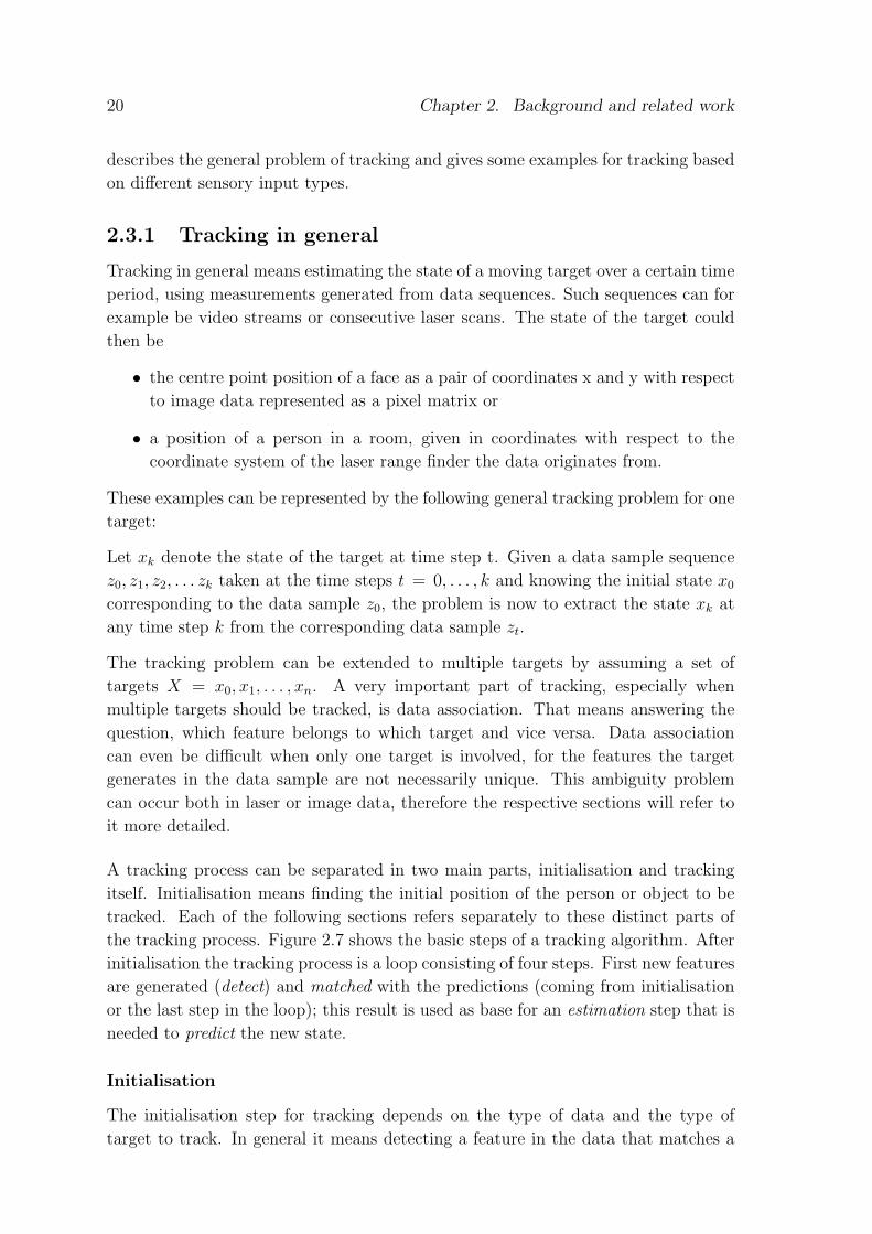
A tracking process can be separated in two main parts, initialisation and tracking
itself. Initialisation means finding the initial position of the person or object to be
tracked. Each of the following sections refers separately to these distinct parts of
the tracking process. Figure 2.7 shows the basic steps of a tracking algorithm. After
initialisation the tracking process is a loop consisting of four steps. First new features
are generated (detect) and matched with the predictions (coming from initialisation
or the last step in the loop); this result is used as base for an estimation step that is
needed to predict the new state.
Initialisation
The initialisation step for tracking depends on the type of data and the type of
target to track. In general it means detecting a feature in the data that matches a

2.3. Tracking for interaction 21
Initialise Detect Match
Predict Estimate
Figure 2.7: The tracking process. First the tracker has to be initialised, then the
predict and match loop is entered
representation of the target. This step is described more detailed for the different
types of data used for tracking.
Estimation and Prediction
The loop of estimating, predicting and updating (matching) can be in general based
on Bayes theorem. [AMGC02] presents an overview of different filter techniques that
are based on this basic idea. The goal is, to give an estimation for the probability
of the target state xk at step k based on the known measurements zi, i = 1, .., k
or shorter z1:k. This is achieved with the two steps prediction and update. The
prediction computes the prior probability density function (pdf) p(xk|z1:k−1) via the
Chapman-Kolmogorov equation:
p(xk|z1:k−1) =∫
p(xk|xk−1)p(xk−1|z1:k−1)dxk−1, (2.1)
the update from prior to posterior pdf is done with Bayes’ rule
p(xk|z1:k) =p(zk|xk)p(xk|z1:k−1)
p(zk|z1:k−1)(2.2)
with the normalising constant
p(zk|z1:k−1) =∫
p(zk|xk)p(xk|z1:k−1)dxk. (2.3)
The state sequence itself is assumed to be given by xk = fk(xk−1, vkk − 1) where fk is
a possibly non-linear function of xk−1 and vk−1 is a noise sequence. The measurement
sequence can be described respectively as zk = hk(xk, nk) where hk is a possibly non–
linear function and nk a measurement noise sequence.
Kalman filter One classic filter is the Kalman filter which assumes that the poste-
rior density is Gaussian at every step k. This invokes some more assumptions about
parameters and functions:
• vk − 1 and nk are from Gaussian distributions of known parameters
• fk(xk−1, vk−1) is known and linear

22 Chapter 2. Background and related work
• hk(xk, nk) is known and linear.
In other words, the movement of the target must be predictable as a linear process
and a missing measurement due to occlusion causes problems for the tracking process.
Monte Carlo filters – Particle filter A Monte Carlo filter is a filter based
on the Sequential Importance Sampling (SIS) algorithm. Various approaches to
Monte Carlo filters are known as bootstrap filtering, condensation algorithm, particle
filtering, interacting particle approximations and survival of the fittest. The basic
idea is to generate a set of N weighted samples that all represent a more or less likely
state of the tracking target. These samples can be written as (xik, w
ik), i = 1, ...N
where xi0:k is the state of the ith sample at time step k and has the weight wi
k.
{xi0:k, w
ik} is then a random measure for the posterior pdf p(x0:k|z1:k), where x0:k
is the set of all states of the target up to step k. With the weights normalised to∑i w
ik = 1 the pdf at step k can be estimated as
p(x0:k|z1:k) ≈N∑
i=1
wikδ(x0:k − xi
0:k). (2.4)
The weights are computed using the principle of Importance Sampling, which is
explained in [AMGC02] with reference to [Dou98]. With a proposal, a so called
importance density q(·) samples xi0:k ∼ q(x0:k|z1:k) can be obtained by augmenting
each existing sample xi0:k−1 ∼ q(x0:k−1|z1:k−1) with xi
k ∼ q(xk|x0:k−1, z1:k). Thus, in
each step the samples (particles) are assigned a new estimation of the target state
and a new weight, according to the more detailed description in [AMGC02].
The advantage of these filters is, that constraints for the functions that describe the
state and measurement sequences are more relaxed than for Kalman filtering. A
particle filter as for example used in [SBFC01] is much more robust to occlusions
and measurements missing temporarily.
Data Association
Two approaches to solving the data association problem will be presented within
the respective examples of tracking methods in the following sections. One of these
approaches is based on a statistic Bayesian method, the other is a more heuristic
anchoring technique.
Summary
In this section the tracking process in general was explained. Tracking is one very
important task for any interactive interface for a service robot, as it might be used to
detect the user and focus on her. Another purpose is tracking for gesture recognition
which can also be part of an interactive interface. The next section will give some
examples of recent work of person tracking using laser range data.

2.3. Tracking for interaction 23
2.3.2 Tracking with laser range data
A typical laser range scan contains a set of n + 1 distance values, covering a certain
angle in a planar scan. The distance values are achieved by measuring the reflecting
time for each laser light beam when it comes back after it reached the next object in
its particular direction. Laser range data is easy to interpret, but the only information
it provides is in fact the front position of an object at a certain height. Laser range
finders are often used for a robot’s self-localisation or to track people and other
moving objects that do not leave the scanning plane by moving up or down (like
hands, for example). All examples consider person tracking, as localisation is not in
the main interest of this thesis.
Detecting persons in laser data
Two main cues can be considered, when a person should be detected with the help
of laser data. The first one is shape, the second movement.
Shape There are quite a lot of systems that are based on shape and even those
can be separated as the following paragraphs suggest. The decision, which approach
to use is in this case mainly driven by the used hardware, as the two approaches
require the laser range finder at a certain height respectively.
Body shape The shape of a person’s body can be a cue, as presented in [Klu02].
The author of this publication points out that a person causes a convex pattern in
the scan. Such patterns are relatively easy to find by using the convex hull of the
poly-line the data points describe. If a convex feature is detected, it can be checked
for appropriate size, which can be estimated from minimal and maximal assumed
person width and the distance. However, even with this size constraint an algorithm
that only uses body shape would find lots of “people” that turn out to be furniture,
screens and other static objects that happen to have the width of an average person.
Shape of legs A rather popular approach is to look for legs, i.e. look for a
pattern in the scan that represents two leg-wide convex minima in suitable dis-
tance. This approach is used for example in [KLF+02] and [FZ00]. The presented
approaches work quite well, but a problem referred to in [FZ00] are long skirts or
other clothes that make the legs invisible. In this case the system would in fact fail
to detect the person at all, whereas the search for body shaped features produces
rather false alarms than failures. A method to reduce the false alarm rate for the
body shape detection is to use a second cue, for example motion.
Motion One approach to get a first guess, which of all detected person-like objects
is actually a person, is to take motion into account. If the “person” does not move
at all (or could even be found as a static object in some a priori known world map) it

24 Chapter 2. Background and related work
is not longer considered a person. In [SBFC01] this is done with a grid representing
positions in the world map of a mobile robot. First, the probability for legs being
detected at grid position (x,y) relative to the robot, P (legskx,y), is computed. The
next step is to distinguish between static and moving objects (or persons) by looking
for changes in consecutive scans. Therefore, local occupancy grid maps, with respect
to [ME85] are used. Based on those, the probability P (newkx,y) that an object (or
person) has moved to a new position (x,y) can be computed. As the movement of the
robot has to be considered, too, the built occupancy grid maps have to be matched
first, which is done by a scan matching technique as presented in [LM94].
As the used laser range finder was mounted too high for the leg detection approach
(see appendix A for technical details), the implementation presented in chapter 4
uses a combination of body shape and movement to detect possible users.
Estimating current positions of persons
After a person is detected and the initial position is known, the next step is to find
the person again in the succeeding laser scan, based on estimation, prediction and
update (matching) as described before.
[SBFC01] presents for example the use of a special particle filter version (see above)
which also solves the association problem for multiple targets. This particular filter
is called a Sample Based Joint Probabilistic Data Association Filter (SJPDAF). The
idea here is to do the data association with the help of a Joint Probabilistic Data
Association Filter (JPDAF), a technique that computes the posterior probability βji
that a feature j was caused by person i at a time step k:
βji =∑
θ∈Θji
P (θ|z1:k) (2.5)
where Θji denotes the set of all valid joint association events θ. Such a joint associ-
ation event is a pair (j, i) and determines which feature is assigned to which person.
P (θ|z1:k) is the probability to get the association θ if the sequence of measurements
z1:k is observed. P (θ|z1:k) can be computed using Bayes’ rule and the assumption
that the whole estimation problem is Markov to
P (θ|z1:k) = αp(zk|θ,Xk)P (θXk) (2.6)
where α is a normaliser and Xk represents the state of all persons at step k. This
computation can further be based on the general idea of Bayesian tracking (see
above). The last step is then to use the so derived prediction and update rules for
a set of samples which invokes a particle filtering process. Details are described in
[SBFC01] where also the use of such a combined approach is pointed out clearly. The
authors state, that, besides the advantage of particle filters compared to a Kalman
filter, the combined method with data association makes the association even more

2.3. Tracking for interaction 25
robust to occlusions. A particle filter used for multiple moving persons would in case
of occlusions tend to set the samples on the remaining “visible” persons and loose
the occluded one. The SJPDAF is – according to the authors – capable of handling
this problem, too.
When the person tracking for the implementation within the work of this thesis had
to be done, the first idea was to base it on a method related to the presented one.
But during first tests it turned out that under particular assumptions (see chapter 4
for details) a much simpler approach worked sufficiently well.
Summary
This section presented some particular approaches to detecting and tracking persons
with the use of a laser range finder and explained the relations to the implementation
conducted for this thesis.
2.3.3 Tracking using computer vision
Tracking based on computer vision can be used for different purposes. One is the
tracking of a person, another is tracking of a person’s actions, movements and poses.
Of course, this differentiation is a bit artificial, as both types of tracking have to
handle basically the same problems, but for the presentation of different approaches it
seems to be adequate to distinguish between those purposes at least for the detection,
i.e. initialisation. Some of the presented approaches handle 2D-data, others are based
on 3D-data from a stereo camera system. Only approaches to the detection of the
targets are used, as the tracking process can be described basically similar to the
approaches presented before.
Detecting persons in images
Two cues are used rather often to detect persons or person related targets like hands
and faces in images. These are skin colour and shape. [San99] describes an approach
for the detection and tracking of a user’s face and hands, which is based exclusively
on skin colour. The author had to assure certain constraints for the user’s position
relative to the used camera to make sure that this approach was successive. Such
constraints can not always be met in a flexible environment.
In [BBB+98] a combination of four cues for user detection is proposed. The authors
use skin colour detection, shape template matching, facial structure and a motion
cue to determine a user’s position from an image sequence. In this case the whole
person is detected, but the general idea of using a shape cue in addition to colour
could also be helpful for hand posture tracking and recognition.

26 Chapter 2. Background and related work
2.3.4 Combining laser data and vision for tracking
As this thesis presents an approach of combining laser range data, vision and speech,
the following tracking idea based on those types of sensory data is one of the most
inspiring ones. In [KLF+02] an approach to tracking for interaction based on laser
range data and image processing is presented. The results are integrated with the
help of an anchoring method, proposed in [CS00], that allows to solve the data
association problem for different types of data. Th initialisation is achieved from
laser range data by looking for legs. If the parallel run face detection also succeeds
for this position, the user is tracked. Both cues, position information from laser
data and face position information from the image processing a used continuously to
track the user and her face. In delimitation to this approach the system presented
in chapters 3 and 4 uses the face detection only for verification, the tracking itself is
based on laser range data exclusively.
2.3.5 Summary
This section named some approaches to detection and tracking of hands, faces or
persons in images. Similarities to the approach maintained in this thesis were pointed
out as well as delimitations.

27
3 Design of an interactive
interface
This chapter describes the approach to a generic interaction interface for service
robots. The first section explains how an interactive system should present itself
towards a user. In the second section an approach to a generic interaction system
design is proposed. The following sections describe the principles that are used to
build a scenario based part of such a system.
3.1 Goal oriented interaction for service robots
A (mobile) service robot is a robot that provides services, i.e. performs certain ac-
tions to fulfil a task or mission, to users within a certain environment and context.
The service robot is not personally associated with a single user. Communication
(task specification) has to be initiated by the users.
Interaction is used as a mean to specify the particular service that should be per-
formed in the respective situation. This implies that the robot has not only all
primitive behaviours available, that are needed for navigation, planning and per-
formance of tasks, but is also equipped with an interactive interface that makes an
unskilled user capable of communicating with the robot.
In the following sections, the demands an interactive interface for such a robot has
to comply with, will be discussed.
3.1.1 Use cases
First, the question is “why and when would a person want to interact with a service
robot?”. This section tries to answer that question. The cases of interaction between
user and service robot can be reduced to the four basic use cases shown in figure 3.1.
The actor “User” is connected to all four cases. On the robot’s side it is useful to
separate the primitive behaviours that involve the robot itself as action performing
actor and tasks or system functionalities. The latter are provided by the interactive
interface and can use primitive behaviours. For example, a grasping behaviour would
be a primitive behaviour that is involved in a fetch-and-carry mission or task. Thus,
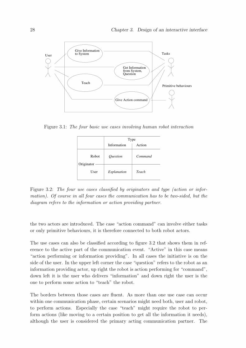
28 Chapter 3. Design of an interactive interface
UserGive Information to System
Teach
Get Informationfrom System,Question
Give Action command
Tasks
Primitive behaviours
Figure 3.1: The four basic use cases involving human robot interaction
Robot
User
Information ActionType
Question Command
TeachExplanation
Originator
Figure 3.2: The four use cases classified by originators and type (action or infor-
mation). Of course in all four cases the communication has to be two-sided, but the
diagram refers to the information or action providing partner.
the two actors are introduced. The case “action command” can involve either tasks
or only primitive behaviours, it is therefore connected to both robot actors.
The use cases can also be classified according to figure 3.2 that shows them in ref-
erence to the active part of the communication event. “Active” in this case means
“action performing or information providing”. In all cases the initiative is on the
side of the user. In the upper left corner the case “question” refers to the robot as an
information providing actor, up right the robot is action performing for “command”,
down left it is the user who delivers “information” and down right the user is the
one to perform some action to “teach” the robot.
The borders between those cases are fluent. As more than one use case can occur
within one communication phase, certain scenarios might need both, user and robot,
to perform actions. Especially the case “teach” might require the robot to per-
form actions (like moving to a certain position to get all the information it needs),
although the user is considered the primary acting communication partner. The

3.1. Goal oriented interaction for service robots 29
following scenario explains more detailed, how a communication between user and
robot can involve more than one of the use cases.
User : Hello Robot [establish communication]
Robot: What can I do for you? <in basic communication state>
User : Follow me [command: follow]
Robot: OK <follows>
User : Now I want to show you something [teach]
Robot: OK <"watches">
User : This is the new mail box <points> [teach]
Robot: Storing ‘‘new mail box’’
to map at position *current position*
Robot: Anything else I can do? <back to basic communication state>
User : Uhm, what’s the time? [question]
Robot: It is *time*
User : Thank you robot, bye. [stopping communication]
Robot: Bye <returning to wait state>
This scenario suggests also, that the first step (establishing communication) is com-
mon to all use cases and has nothing to do with the respective use case itself. This is
also true for the end of the communication. As the service robot is not permanently
attached to one user it should be released so that it is clear that the communication
with this particular user is finished.
3.1.2 Recognising the actual user
In order to be able to establish the communication, the user has to be recognised.
This is in fact one of the most important parts of an interactive interface for a
service robot. Additionally the user has to be represented internally, so that she can
be distinguished from other persons being around. Mechanisms to do this will be
pointed out in the respective section of the system design.
3.1.3 Establishing communication and giving feedback
The initiative for establishing a communication is considered to be on the user’s side.
This assumption was also made in [PASM00] and it seems adequate when designing
interaction systems for a service robot. It holds only for the initial phase of com-
munication between a user and the robot. Of course, the system should have the
ability to address a person, if the situation requires this, as pointed out in section
3.1.5. This is in fact a delimitation to a personal assistant that has to take initiative
when reminding persons of certain actions as in [MPR+02]. However, for the work
presented in this thesis it is adequate to make the assumption, that the user has to
initiate the start of communication.
There are different possibilities to express this initiative and, as pointed out in section

30 Chapter 3. Design of an interactive interface
2.1.2, the user should always know if the robot is aware of its surroundings. Thus,
a possibility of “moderate initiative” should be given, for example, if someone walks
up to the robot within a certain distance and stays in the field of view, she should be
considered a possible user and be addressed, or at least informed, that the robot has
noticed her presence and can provide services. The other form of initiative would
be to address the robot directly, which should result in an appropriate reaction like
searching for the user and offer its services.
Depending on available sensors and feedback mechanisms the system has to keep
the focus of attention on the actual user and make this perceptible. A bad example
would be a robot that is focusing on a random person when heading towards a group
of people in which the user is present. Therefore, the system has to provide some
kind of active tracking ability.
Apart from the feedback that is given by “facing” the user, the system should, de-
pending on output facilities and context, give appropriate feedback about its current
state. This feedback has to be perceptible for the user at any time of a communica-
tion phase. A bad example is a robot that gives feedback via a display, but turns the
display away from the user due to for example a rotation that is needed to perform
a certain action.
3.1.4 Communication model
As the system should be able to handle certain scenarios according to respective use
cases, it is possible to suggest a particular model for the communication process.
It is the user who initiates communication, the robot is supposed to react to this.
Now the user has to state what she would like the robot to do, which should trig-
ger an appropriate reaction. Following this principle the whole communication is
somehow turn taking, as it is always one event that triggers a reaction and brings
the communication into a next step or phase. This can be utilised for modelling the
communication process.
3.1.5 Mission (re)scheduling and organising users
This section describes, how an interactive interface should deal with bystanders and
irregular situations. An assumption that has to be made is, that some representation
of users is available that allows, to recognise them. The idea of having a scheduling
mechanism that allows to cope with the example situations described in the following
is to be seen as a suggestion. Once the communication with one user is established,
the system is exclusively attached to this user, with one exception. Consider the
use case “command”: If the given command involves the robot leaving the user in,
for example, a fetch-and-carry scenario, it should be possible to allow bystanders to
establish communication as well. Nevertheless, the system has to be aware that it is

3.1. Goal oriented interaction for service robots 31
still connected to the first user, so that it can report errors and problems to her at
any time. A mechanism that can solve this problem, which was already mentioned
in section 2.1.2 with respect to [HSE02], is to use a state based architecture and
a scheduling mechanism that allows rescheduling for certain missions depending on
the system’s state. Some examples and suggestions will be given in the following.
The examples explain, how the system should behave, section 3.6 refers to the tasks
for the scheduling module. The general scenario is a service robot that meets a
bystander when performing a fetch-and-carry mission for a user.
Providing information
Task
User Ispecification
Task fulfilled (user I)
Meeting other user
Communication with user II
Figure 3.3: The interrupted action is not changed in any way. Communication with
another user is performed in a closed loop, after which the system returns to the
stacked task at the point where it was left.
In this case, the robot meets a user who only asks for information. This means
to start a second communication phase with the respective dialogue which involves
some information exchange (for example the user asks the robot about the time),
complete the communication and continue with the interrupted mission. Figure 3.3
shows this in a diagram. The mission is the same, no rescheduling has to be done,
and the system can “forget” about the second user after the information exchange
is finished.
Performing mission independent actions without rescheduling
Such a scenario could be, that the robot is blocked by something or itself blocks
something, but a person is present. This person initiates communication with the
robot to resolve the problem by navigating the robot to a better position. After that,
the robot continues with its mission from the new position. In this case the mission
itself remains the same, but some new steps in planning the way or self localisation
may be necessary. Figure 3.4 shows this in a diagram. In this situation the system
does not have to store any information about the communication with the second
user.

32 Chapter 3. Design of an interactive interface
Task specificationuser I
End communicationuser II
Reentry in task
Meeting user II
Small, independent task (user II)
Task fulfilled (user I)
Communication user II
Figure 3.4: The mission itself is not changed, but actions have to be re-planned, for
example the reentry might be spatially different from the interruption point.
Rescheduling missions – adding new task
Here, the second user realises that the system could add a second fetch-and-carry
mission to the one specified by the first user, as the second mission is a subset of the
initial one. For example, the robot’s mission is to deliver user I’s mail from the mail
box to the user’s office. The second user’s office is between the first office and the
Task specificationuser I
Task specification user IIreschedule tasks
Meeting user II
Task fulfilled (user II)
Task fulfilled (user I)
Communication user II
Figure 3.5: Missions can be combined, so they are rescheduled.
mail box. So the second user would like to have the robot deliver also her mail to her
office. The mission is similar, the route is about the same, but the tasks themselves
have to be expanded, as shown in figure 3.5. In this case the system would have to
decide, whether it is possible to combine tasks or not. It has to be possible to reject
a task or mission when combination is not possible.
Reporting error – mission abortion
If the robot can not complete the desired action, for example, because the route to
the mail-box is blocked, the system has to realise this error and has to report it to
the user. This is one important reason why the current user should be known to
the system until she makes clear that the services of the robot are not needed any
longer. Figure 3.6 refers to such an error scenario. In this case the mission could be
removed from the schedule.

3.2. An architecture for an interactive interface 33
Problem occursTask specification
Reporting error
Figure 3.6: An error occurs and the action has to be aborted
3.1.6 Summary
This section outlined the basic ideas of how an interactive interface for a service robot
should appear to users. The basic ideas used for the following design approach are
the attention part of communication, which means detecting the user and keeping her
in the focus of attention and the communication phase itself embedded in a scenario
based approach.
3.2 An architecture for an interactive interface
The previous section described the desired behaviour of an interactive interface.
This section now focuses on how this behaviour can be achieved. First, a general
approach to an architecture is described, as it seems adequate to the author. Figure
3.7 shows, which general components would be required and how the components of
the system can be connected to each other. The central component of the system
is the coordination and decision module, referred to as the “control module”. All
information is gathered and decisions for appropriate actions and reactions are made
here. The design of the control module itself is presented in section 3.3. The scheduler
is considered the system component that should provide the task scheduling within
respective missions and can handle rescheduling necessities. It is not designed for
implementation in this thesis, but a general idea how such a scheduler should work
is presented in section 3.6.
Generally, the system has to provide modules and components for the interpretation
of sensory and other input data coming directly from the user. These interpretation
modules build a separate layer between user and control module. Therefore, they
can be kept flexible and exchanges can be made without having any effect on the
control module itself.
The feedback that has to be given to the user is generated in the output module. For
the system presented here, this output module is not designed explicitly, as it seemed
more important to concentrate on the input interpretation first. In general the idea
would be to provide a module, that provides directives on an abstract level and can
then handle those directives depending on the hardware and modalities available on

34 Chapter 3. Design of an interactive interface
User
Robot<push> <push>
Feature extraction
<push>(clarify)
<push><pull>
<push>
Knowledge
<push>
<push><pull>
<push>
<push> <pull>
<push><pull>
Scheduler
<push>
User input Sensory input
Interpretation layer (dialogue...)
Control Module:
decision,Coordination and
TasksBasic planning
Basic behaviours
(world)
User output
Figure 3.7: An architecture for interaction systems. The basic idea is to keep the
coordination very generic, based on an input independent control language. The
arrows mark the direction of information flow, <pull> indicates that the receiver has
to ask for input, <push> suggests that information is sent when available.
the robot’s side.
The world knowledge has to accessible for both, the input interpretation modules and
the control module, as it should be possible to handle certain situations within this
layer directly. For example, a dialogue module could need the general knowledge to
interpret the dialogue for a given context. On the other hand the knowledge should
also be available for the control module, as certain decisions might have to be based
on the general knowledge as well as on the system’s state.
3.2.1 Connection types
For the connections of the modules two types are proposed: Push and pull. A push
type connection is needed in case the data is transmitted
a) regularly and used as a synchronising basis for the system, or
b) asynchronously and irregularly in terms of a certain abnormal event.
A pull type connection is used, if the respective data is transmitted in the form of a
synchronous actively initiated data access.

3.3. Coordination and decisions 35
3.3 Coordination and decisions
The control module is to some extent the heart of the interactive interface. Here, all
decisions depending on interpreted inputs are made. As presented in chapter 2, there
are many possible approaches to integrate information from different modalities and
sensors. Thus, the question is now, what kind of approach would meet the demands
of an interactive interface for a service robot. The first section of this chapter tried to
state, how a service robot should “behave”, this sections discusses how this behaviour
can be achieved.
3.3.1 High level control of communication
Regarding the use cases for a service robot, it seems obvious that three different
phases of communication can be found in all of the cases: a) Establishing com-
munication, or in other words, get into the robot’s focus of attention and b) the
communication phase itself that is related to the use cases and c) releasing the sys-
tem from communication. This implies also, that there should be a possibility to
have the system doing nothing, i.e. waiting for the proper event that leads to the
first communication phase. The four phases suggest a state based approach as they
are entered sequentially, triggered by certain events. The phases pointed out here are
strongly related to the state based approach presented in [ZDH+03], which worked
well for the particular sequentially structured scenario. This relation to a generally
state based sequential structure lead to a finite state automaton as the basic control
structure for a scenario based approach.
The basic automaton
A finite state automaton can be defined as a quintuple {S, s0,X, δ,Sa} where the set
S contains the states, S0 represents the start state of the automaton,X the accepted
input alphabet and δ defines the transition function. Sa consists of the accepting
state of the automaton. In this case, the set of states would consist of
• a “wait” state, in which the system observes the environment for particular
events, which is also the accepting state,
• a “start communication” state, in which the user somehow has to get into the
focus of attention,
• a “communication running” state, in which the user has control over the robot’s
actions via the interaction system and
• a “going home” state, in which the system goes back to the “wait” state, which
could for example involve moving back to a “home” position.
The start state is obviously the “wait” state and the accepted input alphabet consists
of every event of the environment that can be interpreted by the respective module.

36 Chapter 3. Design of an interactive interface
LOOKING FOR USER/ACTORWAITING
COMMUNICATERESET COMM.
Event: Possible user detected
Internal event: reset done
Internal event: Actor found
Event:Released by actor
No possible actor found
Additional possible user detected
except releaseEvent: Any input from actor,
No relevant event
Figure 3.8: The basic finite state automaton for interaction control. The start and
accepting state is marked with a double surrounding line. State switches depend either
on external irregular events and inputs or on the system’s perceptions.
The transition function is explained with the help of figure 3.8. The figure introduces
the particular user as “actor”. This notation will be maintained for the following
sections, as it allows to distinguish between a general user of the system and the
particular one who is the one to communicate with the system at a certain time.
Unfortunately this expression can be confounded with the UML-Use Case-Analysis
definition of an “actor” (see [FS00] for details), but references to this more general
notation will be indicated respectively.
Events, that control the automaton can be
• explicit external events and input from the user or
• implicit events resulting from the ongoing interpretation of the input data.
An explicit external event in the “wait” state could be a person who is walking
up to the robot, which – depending on the used sensory systems – might cause a
“moving person perception”, that initiates a state switch. In the “communicate”
state external events are, for example, commands or questions uttered by the user,
perceived gestures that can be interpreted within the context, etc. One special event
in this state is the occurrence of a releasing input, like for instance a “good bye”
uttered by the actor or the click on some “communication stop” button. This causes
a next state switch.
Implicit events are independent of the actor’s intentions. An example is the detection

3.4. Proposed modalities 37
of the actor. The system is triggered to search for the actor by her appearance as an
explicit external event, but the implicit event “actor found” results from the triggered
data interpretation. The user can not explicitely force the detection by any action
or utterance.
As the presented automaton describes only the control loop on a very abstract level,
it seems obvious that the states have to be refined and might be replaced by two or
more sub-states, particular sub-automatons or other types of subsystems. The type
of this refinement depends on the states and the types of input considered.
3.4 Proposed modalities
So far a rather generic approach to an interactive interface was described. The
following sections will refine this approach to a design for a specific set of modalities
and sensory data types.
The following paragraph motivates a particular set of data types as one possible set
to handle at least one example scenario based on the “teach” use case.
3.4.1 Scenario related demands
In the first sections of this chapter the demands to comply with were pointed out as
• keep the user in the focus of attention and let her know this fact,
• be able to observe actions and explanations in a teaching scenario, and
• accept and interpret control input.
These demands to the behaviour lead to some needs for the system, as presented in
the following.
3.4.2 Demand related needs
The following system components can cope with the respective demands:
• Robust and fast person tracking ability. Can be done for example with
1. laser range data
2. stereo vision
• Active face tracking. Can be done for example with
1. vision based face detection, combined with position information (person
tracking) and a controllable camera

38 Chapter 3. Design of an interactive interface
2. vision based face detection, combined with position information (person
tracking) and output on a graphical interface to show the focus of attention
• General feedback. Can be given for example with
1. text to speech output
2. graphical output on a respective interface
3. textual output on some screen (uncomfortable)
• Observing the user’s actions (pointing gestures). Can be done for example with
1. vision based tracker and gesture recognition, combined with position in-
formation (person tracking)
2. stereo vision and gesture recognition
3. map on graphical user interface for pointing to positions and mapped
objects
• Accept and interpret control input and explanations. Can be done for example
with
1. speech recognition and processing
2. vision based control gesture or sign language recognition
3. textual input (very uncomfortable)
4. command buttons on a graphical interface
The listed components can be seen as suggestions, which techniques can be used to
handle the demands.
3.4.3 Available components
Due to external circumstances the decision for the set of modalities has to be made
according to already available components and hardware, which are
• a single camera on a pan tilt unit
• a laser range finder
• a skin colour detection based visual head and hands tracker (2D)
• a speech recognition system
• a text to speech system for spoken output
These components can be used as a basis to propose the following approach.
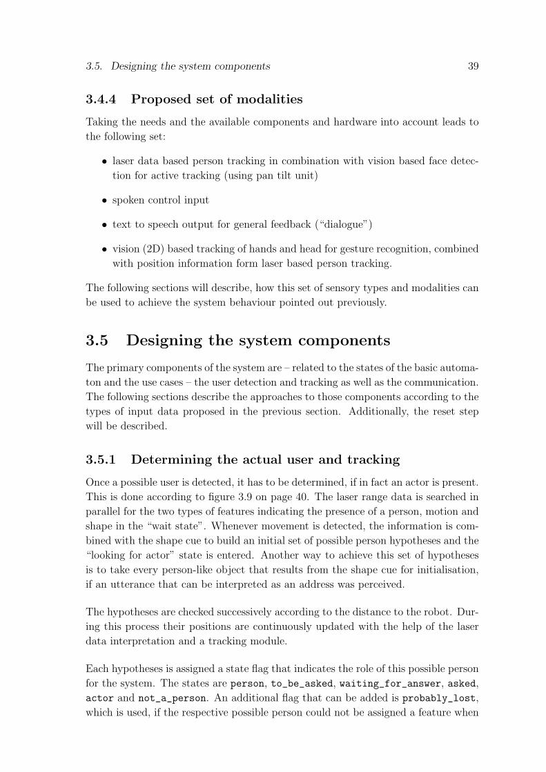
3.5. Designing the system components 39
3.4.4 Proposed set of modalities
Taking the needs and the available components and hardware into account leads to
the following set:
• laser data based person tracking in combination with vision based face detec-
tion for active tracking (using pan tilt unit)
• spoken control input
• text to speech output for general feedback (“dialogue”)
• vision (2D) based tracking of hands and head for gesture recognition, combined
with position information form laser based person tracking.
The following sections will describe, how this set of sensory types and modalities can
be used to achieve the system behaviour pointed out previously.
3.5 Designing the system components
The primary components of the system are – related to the states of the basic automa-
ton and the use cases – the user detection and tracking as well as the communication.
The following sections describe the approaches to those components according to the
types of input data proposed in the previous section. Additionally, the reset step
will be described.
3.5.1 Determining the actual user and tracking
Once a possible user is detected, it has to be determined, if in fact an actor is present.
This is done according to figure 3.9 on page 40. The laser range data is searched in
parallel for the two types of features indicating the presence of a person, motion and
shape in the “wait state”. Whenever movement is detected, the information is com-
bined with the shape cue to build an initial set of possible person hypotheses and the
“looking for actor” state is entered. Another way to achieve this set of hypotheses
is to take every person-like object that results from the shape cue for initialisation,
if an utterance that can be interpreted as an address was perceived.
The hypotheses are checked successively according to the distance to the robot. Dur-
ing this process their positions are continuously updated with the help of the laser
data interpretation and a tracking module.
Each hypotheses is assigned a state flag that indicates the role of this possible person
for the system. The states are person, to_be_asked, waiting_for_answer, asked,
actor and not_a_person. An additional flag that can be added is probably_lost,
which is used, if the respective possible person could not be assigned a feature when

40 Chapter 3. Design of an interactive interface
+
+
Motion
Shape
Tracker
Images/Camera
Adress
Motion detected
update
no possible actor left (false alarm)
actor determined
Face detection
Person set Verification
Confirmation
Speech actSpeech Server
LaserFocus on nextpossible actor
Figure 3.9: The process of the detection and determination of the actor
positions are updated.
Either the set of hypotheses is searched for the closest hypothesis having the state
person or the one, that has already been verified by face detection and is now in the
confirmation process as to_be_asked or waiting_for_answer is still in the centre
of interest after the update.
If the state of the actual hypothesis is person, the vision based faced detection is used
for the verification of the “person-hypothesis”. If verification fails, the hypothesis is
assigned not_a_person, in case of a success the state is changed to to_be_asked and,
when the system uttered a request for confirmation, set to waiting_for_answer.
The system expects now a confirmation or rejection, which sets it in the communi-
cation state and the person to actor, if the actor is confirmed, or back to the search
within the set of hypotheses, with this possible actor set to asked. If no actor is
found and no possible actor is left in the set of hypotheses the system switches back
to “wait”.
3.5.2 Communication
When communication is established, i.e. the actor is confirmed, the system needs to
keep the focus on her. Therefore, the tracking and position update loop is maintained

3.5. Designing the system components 41
during communication as long as no action is required that makes the robot move
out of the scene. Figure 3.10 shows this as a separate process. The motion and
+
Motion
Shape
Tracker
update
Speech actSpeech Server
Laser Verification
Face detection
Images/Camera
ActorError
command
Handlecommand
Sub−state
Figure 3.10: The check for the presence of the actor in the communication phase.
shape cues from the laser data interpretation are used to update the actor’s position.
If this update or the following verification with the face detection fails, the actor is
marked as lost and the system switches to an error state. Otherwise the interpreted
input from the speech server is used to determine the demanded action. The system
switches into the respective sub-state.
Communication supported by speech and gestures
As the scenario that should be handled involves a “teach” sequence, this section con-
centrates on the description of the integration process for speech and gestures. Figure
3.11 shows the combination of those modalities after the respective state is reached.
In this case the vision based head and hands tracker is used to determine a certain
motion of one hand which will be interpreted as a pointing gesture. The resulting
position is used to be assigned to the object name, resulting from speech interpre-
tation. The speech system would accept an explanation only, when this particular
sub-state is reached. The handling of spoken input and integrated representation of
information will be described in the following section, as it is important in all states
of the system.
3.5.3 Control input: Language processing
Language, or in this case speech processing, is proposed as the central modality
for the control module. Most state switches in the controlling automaton are trig-
gered by some explicit utterance. Therefore, it is useful to take a closer look into
the structure of commands and other utterances. Considering the four basic use
cases, user utterances can be represented as explanation, question or command, with
the assumption that the use case “teaching” involves the basic types command and

42 Chapter 3. Design of an interactive interface
watch hands command
Back to basic communication state
Camera/Images
Tracker
Speech server
Interpreter
Confirm
Explanation
InternalRepresentation
Figure 3.11: The integration of speech and gestures depending on the system’s state.
explanation. Additionally, some other types of utterances are needed, independent
from the modality. These would be address and response, which are necessary for the
control of communication (getting the attention of the robot, confirming or rejecting
on questions of the robot, etc.).
Those five types of utterances are not very specific, therefore it is necessary to refine
them in a taxonomy of utterances. To make things simpler, those utterances will be
called “control input” in the following, with respect to the idea that the representa-
tion presented here can be used for different types of input data. Figure 3.12 shows
the taxonomy for some examples of specific spoken utterances. This taxonomy is not
complete, it is obvious that, in particular for the control input “command”, lots of
additional specifications could be made. However, with such an abstract representa-
tion it is possible to add a new “command” quite easily.
When taking a closer look into the control inputs it becomes clear that they are too
abstract in their basic form. Thus, a mechanism is needed to explain, for example
for a “watch” command, what object this command is related to. Therefore, the
control inputs are represented as a structure, related to the typed feature structures
used in [Top02] with respect to [Den02] and [DW97]. For example, a “deliver” com-
mand, drawn from the input “Robot, deliver the mail to the living room” can be
represented as:
ControlInput:
[ Command:
[
Command type: DELIVER
Command object: MAIL
Command direction/location: LIVINGROOM

3.5. Designing the system components 43
Response
NoReject
Address
ByeGoodbye
Explanation
HelloAttention
ObjectThis is the table
LocationYou are in the living room
Question
LocationWhere are you
TaskWhat are you doing?
Command
FollowCome with meFollow me
Look at meWatch meI want to show you something
Watch
Go to the door, pleaseGo
YesConfirm
... etc.
DeliverDeliver mail
ControlInput
Figure 3.12: The taxonomy for different types of control input.

44 Chapter 3. Design of an interactive interface
]
]
With this representation it is also possible to use a particular representation for
objects and location depending on a world model. For this thesis the objects and
locations are represented as strings and interpreted respectively. This is sufficient
for the used parsing strategy and interpretation level of speech.
3.6 Scheduler
In section 3.1.5 the utility of rescheduling tasks was explained. This idea is not
designed to implementation level here, but some basic principles can be presented
anyway. When the use cases were described, high level and basic behaviours were
separated. Some commands, as described in the section above, might cause the
coordination module to invoke a basic behaviour, like for example “go to the table”.
In this case only the position of “the table” has to be known and the task is rather
basic. It is not useful to make an interruption and rescheduling of such a mission
possible. A command like “deliver mail to me” needs more tasks, like
1. leave the room,
2. go to mail box,
3. pick up mail for user,
4. go to user’s office,
5. enter room and
6. “hand over” mail.
In this case it could be possible to store these tasks in a scheduling module to make
an interruption possible. For example, as in the scenario in section 3.1.5, a second
user could meet the robot during subtask 2 (go to mail box) and ask it to deliver her
mail, too. Rescheduling is possible, and the new plan could be:
1. go to mail box,
2. pick up mail for user I,
3. pick up mail for user II,
4. go to user II’s office,
5. enter room,
6. “hand over” user II’s mail,
7. leave the room,

3.7. Summary 45
8. go to user I’s office,
9. enter room and
10. “hand over” user I’s mail.
Whenever a task is done and no interruption occurred so far, the scheduler sends
the following task to the basic planning level. In this level it is assumed that a
planning module exists. This module is responsible for planning the way from A to
B (from the room to the mail box), refine the “pick up mail” task into approaching
and grasping and handle these phases, etc.
3.7 Summary
This chapter presented the principles that were used to design an interactive interface
based on some example scenarios. The chapter gave an idea of how an interactive
system should behave towards a user, and specified needed modules and components.
An abstract representation for control input was presented. This representation can
be used for the main input type. Most systems might implement this based on spoken
input (as done in the implementation work for this thesis) but others might be based
on a set of gestures or sign language. Other input data interpretation (vision and
laser data) was presented rather superficially, but will be explained more detailed
with the background of an implementation in the following chapter.


47
4 Experimental implementation
using laser data, speech and vision
This chapter describes the implementation of a scenario based part of the interactive
interface design described in the previous chapter. The implementation combines
the proposed set of modalities and sensory types. Some of the required components
already existed, or could be derived easily from existing programs, but others had to
be implemented from scratch. In general, the system components are kept modular
so that an easy exchange is possible. The implementation gives an example for
the principles of input coordination presented in chapter 3 and concentrated on the
following questions:
• Is it possible to integrate simple components on a rather abstract level to de-
rive an interactive interface to control a robot? In [ZDH+03] this question was
already answered positively by integrating dialogue and vision based tracking
on a high level of abstraction. In that case, though, the two integrated modal-
ities dialogue and vision based face tracking were run in parallel but did not
influence each other. In this implementation speech and a combination of vi-
sion and laser data based tracking are used to control the system. This means
that integration of results from different input cues is not only sequential, but
might be continuous within the respective state of the sequential process.
• Is it possible to use a state based gesture and speech integration concept that
allows to use a tracking system for dynamic gestures in order to recognise
pointing gestures?
• Does the integration of different modalities and sensory systems help to achieve
an interactive system that follows the principles of interaction pointed out in
chapter 3?
4.1 Background for the implementation
The underlying principles for the implementation were described in chapter 3. In
the following sections the concrete implementation of those ideas will be presented.
The system should be able to handle the following main scenario:
48 Chapter 4. Experimental implementation using laser data, speech and vision
• A user walks up to the robot
• the robot detects the user and determines her as actor
• the user wants to explain something to the robot
• the robot observes a pointing gesture and an explanation.
In order to achieve this, it was necessary to implement the complete basic FSA
as described in chapter 3. Within the communication state some sub-states are
implemented to make related scenarios possible as well to show the flexibility of the
approach. Some assumptions about the interaction in the scenario have to be stated
and will be presented before the implementation work is explained.
4.1.1 Interaction assumptions
The following assumptions are useful to keep the main interest on the integration of
modalities and not on the respective modules themselves.
• People who want to interact with a robot or other person would be fairly close
to their interaction partner, so the field of interest for the robot is thresholded
in terms of distance.
• People would come closer to their communication partner, if the distance is
too long in the first place.
• If somebody decides after a rather long time being in a certain room to com-
municate with somebody else, who has also been in this room for the same
time, she would verbally address the communication partner.
• People who want to communicate would at least initially turn their face towards
the communication partner.
• People who want to communicate would always try to stay in the focus of the
communication partner and would not try to irritate the partner by moving
around a lot. An exception to this is of course a situation in which the partner
(or robot) is asked to follow.
• If one person communicates obviously with another person (or in this case a
robot), a third person would usually not walk between the two communicating
persons, if there is another way to walk by.
• The robot is not moving while waiting for somebody to interact with it.

4.2. The coordination module 49
4.2 The coordination module
As proposed in chapter 3, the control module is implemented as a finite state au-
tomaton corresponding to the one presented in section 3.3.1, with
S = {idle, waiting, search actor, actor found}
S0 = waiting
X = {{interpreted laser data}, {interpreted vision data},{interpreted speech data}}.
Including the necessary sub-states and the error state, the whole FSA of the control
module is presented in figure 4.1 on page 49. The sub-state searching is needed
Event: Possible user detected
No possible actor foundInternal event: reset done
SEARCHING
No relevant event
SEARCH_ACTOR WAITING
IDLE.
CONFIDENCE_LOST .
Perceived "Good Bye"
actor lostinternal:notification done
Perceived "hello"
Perceived confirmation
Personset initiated
Additional possible user detected
done
Teach command
BasicCommand
done
Teaching in progress part of action still to perform
RUNNING_CMDd
W_POINTING
ACTOR_FOUND
Figure 4.1: The FSA used for the implementation. The figure shows the whole au-
tomaton including the error state confidence lost and the necessary sub-states.
to initialise the person set for the search actor state, without the perception of
a moving person. Otherwise the initialisation is done immediately after the percep-
tion occurred. When the basic communication state actor found is reached, the
system can be triggered to switch into two different sub-states, either w pointing
or running cmd. The first is used in the “teach” use case and is reached, when
the system is instructed to observe the actor’s actions. The latter is used to define

50 Chapter 4. Experimental implementation using laser data, speech and vision
the system’s state in case that a command occurred, which can be handled by the
current underlying planning system. This connection to the planning system will be
described more detailed in section 4.4.6.
The following sections describe the handling of the input data and the different states
with the input accepted respectively.
4.3 Modalities and types of input data
The implementation work is done for three different types of input data: Laser range
data, images and speech. With these the two modalities speech and vision based
gesture recognition are supported by the position information achieved from the
laser range data. The basic control input type is speech and the user detection is
based on laser range data and image processing.
Some of the modules for handling the input were available already. This was the
case for speech recognition and visual tracking. For speech recognition the system
ESMERALDA developed in Bielefeld (see chapter 2 and appendix A) was used. The
visual tracking could be based on the work of Fredrik Sandberg, presented in [San99].
Other modules had to be added, which was the case for the handling of laser data
to achieve position information and the interpretation of spoken input.
The interpretation of the results from the available vision based tracking system
had also to be implemented, as the system in its original form could only recognise
dynamic gestures. The system is embedded in the ISR-System that is developed at
the CAS group. More details about this system are explained in appendix A. Figure
4.2 on page 51 shows the implemented system with the modules for handling the
input. The input from the laser range finder is coming in on a push connection to
make sure that it is not tried to get data when no scan is available. For the speech
handling process also a push type connection is used to get every utterance processed
immediately when it arrives. For the image handling a pull connection is sufficient,
as image processing is needed in certain states only, as will be explained in section
4.4. The tracker for person positions is a separate module, which keeps it flexible for
changes of the tracking approach. It will be explained together with the handling
of laser data in section 4.5.1 as it is based on results from this module. First, the
handling of the persons will be explained, to make the description of the system’s
state more understandable.
4.3.1 Handling person hypotheses - the person set
During the search for the actor usually more than one person hypotheses are created.
As all the hypotheses that turn out to represent objects rather than persons are still
useful when positions are updated, all objects that could be persons are grouped into

4.4. States of the system 51
Speechserver
Laserrange finder
Talkserver
Pan TiltUnit
Planner
Person Set
Parser
Camera
Imageprocessing
LaserdataHandler
ImageHandler
SpeechHandler
Control
<push><push> <pull>
<push>
<push>
Tracker
Figure 4.2: The different modules for handling the input
the person set. Within this set each member is representing an observed object. To
each set member are assigned:
• A position relative to the robot,
• a head height, which is determined with results from image processing,
• an interaction state as described in section 3.5.1, that determines if this object
or person should still be considered as a possible actor and,
• a confidence level.
The confidence level is used to decide, whether the object still can be considered a
person. For example, if it is not moving and no verification of the person hypothesis
with image data can be given for a certain time, the confidence level decreases, so
that the “person” is rather considered an object. In the following descriptions of the
system’s state also the influence of the interpreted sensory data on the person set
will be explained.
4.4 States of the system
This section described the states of the system by explaining influences of inputs on
the state switches and the person set.

52 Chapter 4. Experimental implementation using laser data, speech and vision
4.4.1 Observing the environment: waiting
Initially, the system is waiting for either verbal input or laser detected movement.
The state is related to the first part of the component for user determination de-
scribed in section 3.5.1.
If the speech handling perceives a greeting, the system switches to the state search-
ing to find all possible persons being around. The other way to leave the state
waiting is, when person caused movement is registered. Incoming laser data is
analysed with the help of the laser handler module. The results are hypotheses for
person shaped objects and moving persons. Those are grouped into the person set.
Thereupon the system switches to state search actor to determine the person of
interest.
4.4.2 Searching persons without movement cue: searching
This state is only reached if a greeting is observed in waiting state. In this case the
assumption is, that a possible actor is somewhere around among all person shaped
objects, but not necessarily moving. So the laser data handler is asked for person
hypotheses to built the person set.
4.4.3 Searching for the person to address: search actor
In this state comparably many actions are performed as shown in section 3.5.1. First,
the positions of the objects and possible persons are updated. The basic idea to do
this updating or tracking step was using a particle filter according to [SBFC01]. The
proposed way of statistical data association combined with tracking using a particle
filter would in fact have provided the possibility to track all persons being around
very robustly.
However, in the scope of this work it is not necessary to track all moving objects
or persons over a long time, but find one person of interest - the actor - among
other persons. This can be done with a straight forward approach to detecting and
updating the persons’ positions which will be explained in section 4.5.1.
After the positions are updated, the current person of interest is chosen from the
person set. The assumption here is, that the actor is probably very close to the
robot, if not the closest person anyway. With the pan tilt unit the camera is focused
on this person.
Due to the camera movement the actor gets the feeling of being observed by the
robot, which makes it a lot easier for a person to communicate with the machine.
Now, an image is grabbed and the image handler module is used to decide whether
a face can be found at an appropriate image position or not.

4.4. States of the system 53
If a face is found, based on skin colour detection, the confidence-level for this possi-
ble person is raised, indicating that in fact a person is observed. The idea of using
the skin colour detection as verification only is based on the fact, that the space
of hypotheses for “face” can be reduced drastically by isolating the region where to
look for faces. Therefore, it is not necessary to search for a face, before the camera
is positioned in an interesting direction.
This idea was also used in [KLF+02], where both cues, laser range data results and
image processing were combined by the technique of anchoring. In the work for this
thesis, the results are combined in a cooperative way, each confirming result from
image processing or laser data handling is used to increase the confidence-level for
the current person. Respectively, confidence is decreased, if the hypothesis can not
be confirmed. This is done according to the design decisions presented in chapter
3. A detailed description of the face detection process itself can be read in section
4.5.2.
If the confidence-level for the current person of interest exceeds a threshold, the
person is asked if some service should be provided and marked as possible actor.
Additionally, the head height for this person is now fixed according to the results of
the face finding algorithm, so that at every time the camera can be directed straight
to the actor’s face.
If verification keeps failing for several tries, the confidence-level falls below a mini-
mum threshold. Thus, the “person” is not longer considered a person and the next
– if existing – possible person gets in the centre of interest.
With the assumption that the actor – who really wants to communicate to the robot
- would not try to run away from the robot and would therefore stop at a certain
position, it is reasonable to consider a confident result after a couple of tries, all
providing nearly the same result, at least within a threshold.
The system remains in this state, sticking now to the possible actor, until a con-
firmation comes in from speech handling. In this case the person is set to be the
actor and the system state is set to actor found. If no confirmation comes in
within appropriate time or a rejecting utterance is recognised, the person is marked
as already asked and the next interesting possible actor object is picked as current
person. If no more interesting persons can be picked, the system resets via idle.
4.4.4 Accepting commands: actor found
In this state the system accepts commands generated from results of the speech
recognition. Those commands can be such known by the planner, which means that
they are passed on directly. In this case the system switches to the running cmd

54 Chapter 4. Experimental implementation using laser data, speech and vision
state. Other commands can be those involving more interaction with the person, like
tracking the person’s actions. If one of those commands used internally appears, the
system switches to the related sub-state. The processing of the recognised sentences
is explained in section 4.5.3. If confidence for the person becomes too low, because of
detection failures either with the laser handler or the image processing, the system
is switched to the error state confidence lost.
4.4.5 Recognising gestures: w pointing
This state represents the context of watching a pointing gesture. If it is reached, the
system determines, if the distance from robot to actor is appropriate for the vision
based tracking module. If this is not the case, an optimal position is calculated
and the robot is moved there. This is done by sending a respective command for a
movement to a certain poaition relative to the current position to the planner (see
section 4.4.6). If the distance is considered appropriate, the visual tracker is started.
The tracker is integrated in the image handling module and was available when the
work was started.
Results of the tracker are used to determine, if the actor is moving a hand, and if so,
this hand is tracked. When the movement stops, the system considers the gesture
as finished and stores the hand position relative to the robot. An assumption is,
that the actor is pointing in the same plane as she is standing in. This assumption
has to be made, because the image processing is based on one camera, so no depth
information for the image is available.
During this process the system expects and explanation of the object or location the
actor pointed to. If this explanation is achieved, it is combined with the observed
position. As this is an experimental implementation, the information is not stored,
but repeated together with the position.
After this the user is asked, if something more can be done, and the system is switched
back to actor found.
4.4.6 Running basic tasks: running cmd
Within the framework of ISR (details are described in appendix A), it is possible
to communicate via socket connections with the basic planner of the robot server.
The planner itself is able to handle some commands that can be sent as strings of a
certain format. The connection to the planner can be used to pass on a command
string that is generated in the speech interpretation, for example a respective “move
to <position>”-command, generated from a respective user utterance.
Further, the connection can be use to ask for the state of the process. Thus, in this

4.5. The different modules 55
state the system continuously asks the planner about its progress and waits for it to
report, that the particular action is performed completely. Thereupon the state is
switched back to actor found. The system asks, if anything more can be done.
4.4.7 Resetting: idle
This state is reached, whenever the speech handling module receives an utterance
that is considered a “Good bye”, or when an error occurred. The person set is cleared
and the system starts newly with the initial state waiting.
4.4.8 Error handling: confidence lost
Due to time constraints the error handling is very simple. If the actor is lost, a
respective message is generated and the system is reset to the idle state. In chapter
6 some ideas for a better error handling will be discussed.
4.4.9 Summary
This section explained the states of the implemented system in a rather high level of
abstraction. The idea was to describe, how the system behaves according to those
states. The underlying principles for the handling of interpreted data were already
described in chapter 3 and therefore were left out in this section.
4.5 The different modules
In this section the handling of the input data itself will be described, at least for
those modules that had to be implemented during this work.
4.5.1 Handling laser data
When a new laser scan comes in, the data is run through a median filter. This is
done to reduce the noise in the scan. This filter technique is mostly used in the
field of image processing, but works of course also for one dimensional data. Median
filtering or rank filtering has two advantages compared to the simpler mean filtering
(according to [FPWW]):
• The median is a more robust average than the mean and so a single unrep-
resentative data value in a neighbourhood will not affect the median value
significantly and
• No unrealistic values are created, but one of the existing values in a neighbour-
hood is used to represent a certain data point. This preserves sharp edges,
which helps when looking for certain patterns in a laser scan.

56 Chapter 4. Experimental implementation using laser data, speech and vision
In this case a medianfilter of width two was used, so for each data value the two
predecessing and two successive values are used for the filter process. After the
filtering the data is stored in the laser handler, so that two consecutive scans can be
compared.
As mentioned in chapter 2, the two cues used to detect persons in those two scans
are shape and movement, which will be described in the following. Further, the
approach to the updating of person positions is explained.
Shape
For the shape cue the idea proposed in [Klu02] is used: A human body causes a
convex pattern in the data, at least under the assumption that the person is not
aligned perfectly to another object. This assumption is reasonable for the context of
this experimental scenario.
The filtered scan data is searched for edges, i.e. neighboured data points with a
certain minimum difference between their range values. According to their directions
the edges are marked as left or right edge (left and right seen from the person’s
perspective). Each pair of a left and the next right edge, that represents a convex
pattern of appropriate size, is used to build a first person hypothesis. Only the last
left edge (if a couple of left edges occur after each other) and the first following right
edge are considered a respective pair. The appropriate size (as angle it should cover)
of a person is computed from the distance of the pattern and a threshold for the
average size of a person.
However, lots of objects in an every day environment cause a convex pattern with
the size of a person’s body in a laser scan. Figure 4.3 shows a typical laser scan of
the environment of the used robot. Thus, a second cue is used to decide whether
a person is present or not in the case, that the robot was not addressed directly.
In such a case, all hypotheses resulting from the shape cue are used to build the
person set. After an explicit address the presence of an actor is highly probable, and
together with the assumption that the actor is rather close to the system, she will
be detected sufficiently well without the second cue. This second cue is movement.
Movement
With the assumption that the robot is not moving itself when observing the en-
vironment, the detection of moving persons can be based on a comparison of two
consecutive laser scans. When a second data set comes in, the difference between
the scans is calculated for each corresponding pair of data points. In this set of
differences a moving person causes one of two typical patterns, which are shown in
figure 4.4. The data is searched for such patterns as follows:

4.5. The different modules 57
Figure 4.3: A laser scan that shows one person, marked with the arrow and some
other objects that could be persons. Scan data points were connected to poly-lines to
make the scan easier to interpret visually.
• If a peak (both, negative or positive) is detected, a search for a corresponding
peak of the other sign (positive or negative, respectively) is started at the end
of this one.
• If the distance between the end points of the respective peak corresponds to a
certain threshold, the area is stored as person caused movement.
• If a peak only in one direction but of person size occurs, this is also considered
an area of person caused movement.
The areas, in which movement was detected are thereupon mapped to the hypotheses
for positions of possible persons, calculated for the second, actual scan.
The likelihood for each of the observed objects to be a person is increased or decreased
according to the mapping of the two cues. In [SBFC01] was presented, how such a
movement cue can be achieved in case that the robot is moving initially. In this
case the two scans would have to be mapped to each other before a difference can
be calculated. For the presented system this was not in the centre of interest, but as
the laser handler is a module that is independent from the control system, it could
be changed to achieve the possibility of having the robot move initially.
Update – The tracker
Originally, the idea was to base the tracking of the actor and other persons being
around on the approach presented in section 2.3.2 with reference to [SBFC01]. How-
ever, when a straight forward approach of assigning the closest possible feature to

58 Chapter 4. Experimental implementation using laser data, speech and vision
Figure 4.4: These to pictures show the typical patterns a moving person causes in the
difference data of two scans. Left, a move crossways to the scan lines is represented;
the right picture shows the pattern for a move that was directed almost exactly in the
direction of the scan. The single peak in the left picture can be ignored as noise.
each person was tried to test the principles of combining image processing and laser
data based tracking, it seemed sufficient for test purposes. Of course, as will be
pointed out in chapter 5, this tracking approach causes the tracking related system
drawbacks. Those are in fact not too dominant, so the implementation is kept on
the straight forward level.
4.5.2 Handling vision data
The control module triggers the image handler to grab a new image for processing,
whenever results from image data are needed. The image itself is kept in the hand-
ling module, which makes the control module independent from the used hard- and
software for image grabbing. Whenever an image is grabbed, the available features
are drawn. In this case, the image processing is based on skin colour detection, thus
all skin colour blobs1 are isolated in the image data. This is done with the help of
the respective skin colour based blob detection provided in the system presented in
[San99], which was available when the work was started.
The blob detection uses HSV-histograms to determine skin coloured areas in the
images. Details about the user independence of the blob detection are presented in
chapter 5. The system uses a colour model that is achieved with a support program
to determine the skin colour of the user(s).
The detected blobs are now used either for verification of a person’s presence or to
observe actions.
1In the field of image processing a “blob” is a set of connected pixels with the same colour valuein the image. This value can be expressed in different colour spaces, most common are RGB (red,green, blue) or HSV (hue, saturation, value).

4.5. The different modules 59
Verification
If the presence of a person has to be verified, the set of blobs is searched for one
blob of appropriate size and position, that represents a face. The minimum and
maximum sizes in pixels are calculated from distance d in cm, which is known from
laser range data, the opening angles of the camera (α for width and β for height), the
average minimum and maximum size of a face (minWidth, maxWidth, minHeight
and maxHeight in cm) and the image size pixWidth and pixHeight in pixels to
minimum =minWidth
d ∗ tan(α)∗ pixWidth ∗ minHeight
d ∗ tan(β)∗ pixHeight (4.1)
and
maximum =maxWidth
d ∗ tan(α)∗ pixWidth ∗ maxHeight
d ∗ tan(β)∗ pixHeight. (4.2)
The person (or object) to be verified can be assumed at a rather central position,
due to the adjusted camera. Therefore, the result of the verification is positive, if a
blob of appropriate size can be found within a distance threshold from the y-axis of
the image. The distance to the x-axis is not considered determining here, but will be
used to calculate the height of the blob according to distance and camera tilt in the
control module. This height is checked for appropriateness. The thresholds are very
weak here, which causes a rather high false alarm rate but less detection failures if,
for example, a person is seated and addresses the robot. However, together with the
position cue results are sufficient, but could of course be improved by using more
information about the face (shape, relation to other body parts, etc.).
Tracking for detection of pointing gestures
When the system is in the w pointing state, which means that it somehow expects
a pointing gesture, the visual tracking system of [San99] is used to determine, which
hand is moving. The moving hand is then tracked until no more movement is reg-
istered and the final position of the hand in the image is used to derive a position
relative to the robot. As stated before, it has to be assumed that the hand was moved
in the same depth as the actor is standing, because no depth information could be
drawn from image processing. However, the question, if this particular tracking sys-
tem could be used in the context of the state based interactive interface, can be
answered positively, but some improvements would have to be done, as suggested in
chapters 5 and 6.
4.5.3 Handling speech data
Speech data is processed in two different levels. When data from the speech server -
i.e. speech recognition - comes in, it is passed on to the parser. When an utterance is
analysed completely the speech handler - knowing about the system’s state - processes

60 Chapter 4. Experimental implementation using laser data, speech and vision
the parser result and switches states if necessary or sets a planner command which
is then passed on to the planner. This design makes it possible to change the parser
if more natural language dialogue handling becomes necessary, without changing the
handling of parsing results.
Speech acts
According to the control input taxonomy presented in section 3.5.3, a taxonomy for
speech acts was used. In this particular case the basic control input type was imple-
mented as speech act, because only speech is considered relevant for control input.
As the experimental system is kept rather limited in terms of accepted utterances,
only the sub-types address, response, command and explanation are needed
and implemented. The following section explains, how the speech acts are generated
from speech recognition output.
Parser
Human natural spoken language without any constraints is not regular. It is not
even context free, if the difference between grammatically correct written language
and spontaneous speech is considered. Humans tend to repeat parts of sentences or
start sentences in the wrong way, realise their errors and correct them.
Thus, a parsing system for real natural language would need exponential time, ac-
cording to [Roß02], where the author finally chose to build a parsing system for a
context free subset of German, which could be parsed in cubic time. The simplest
kind of language is, of course, a regular one. For this type a parsing automaton
would be sufficient, parsing could be done in linear time. This requires to reduce the
used language to a very restricted subset of (in this case) natural English.
Taking a closer look into the language used here, shows that it actually is sufficient
to work with such a restricted subset of English. Together with the idea of word or
pattern spotting, as mentioned in section 2.2.1, the parsing process for this example
system could be kept rather simple.
The parser is represented by another finite state automaton {S, S0,X, δ} with
S = {waiting for msg, waiting for utterance, parsing start,
parsing want to, parsing attention, parsing response, pars-
ing command, parsing explanation, parsing cmd obj 1, pars-
ing cmd obj 2, parsing expl obj, parsing complete}
S0 = waiting for msg
X = {ROBOT, HELLO, BYE, YES, NO, WATCH, WANT, LOCATE, LOCALIZE,
DELIVER, STOP, THIS, SHOW, YOU}

4.5. The different modules 61
WAITING_FOR_MSG
"ROBOT"
WAITING_FOR_UTTERANCE
PARSING_START
’(’
Explanation word
Ignored words
(THIS)
(IS, THE, TO,...)
Command word
"WANT"
SHOW
YOU
Greeting Response
PARSING_COMMAND
PARSING_ATTENTION
PARSING_RESPONSE
PARSING_EXPLANATION
PARSING_CMD_OBJ_1
PARSING_CMD_OBJ_2
’)’
’;’
’;’ ’;’
’;’
’;’PARSING_COMPLETE
PARSING_EXPL_OBJ
’;’cmd1 = ""
’(’
cmd1 != ""’(’
Ignored words
’;’
’(’
PARSING_WANT_TO
Figure 4.5: The parser as finite state automaton.
A technical constraint to reduce the signal to noise ratio of speech recognition was
the idea of having a certain start word for each sentence2, which sets the automa-
ton from the initial state waiting for msg to the message accepting state wait-
ing for utterance. The incoming utterance is read until a known keyword ap-
pears. According to this keyword the automaton state is switched, as shown in
figure 4.5, and incoming words are used to build a respective speech act. Objects
of commands are not analysed within the parsing, but set into the speech act as
strings. The structure for the representation offers the possibility to integrate an
object hierarchy to analyse objects according to some ontology.
Utterances recognised by the speech server are closed with a semicolon, which makes
it easy to decide whether the utterance is complete or not. If a complete utter-
ance could be parsed the parser returns a filled speech act and is set back to the
waiting for msg state. If the semicolon is read but no useful utterance could be
parsed, the parser returns an error message and is set back to waiting for msg.
2The current start word is “ROBOT”, but could be set easily to something else. It is evenpossible to use the parser without any start word.

62 Chapter 4. Experimental implementation using laser data, speech and vision
This can cause problems if the actor speaks very slowly and adds long pauses after
each word. If no input appears for a certain time, the speech recognition system
closes the utterance, i.e. adds a semicolon. In this case the parser would recognise a
series of messages that make no sense according to the current system state. In this
case it returns an error message, that is used to produce a respective utterance so
that the actor knows about the problem.
Speech handler
The speech handler knows about the current system state. Thus, it can update the
system state according to the speech act resulting from the parsing. If the resulting
speech act is either a command or an explanation, a filled object string is expected.
If this is not present, the speech handler returns an error message which will be used
to prompt the user. As the speech handling module does not store the state of the
dialogue and therefore loses information about previous speech acts, the user will be
prompted to repeat the complete utterance. Here a better designed dialogue system
could help, for example in analogy to the system presented in [Den02].
Summary
This section presented the implemented modules and the algorithmic ideas used for
them. It has to be stated, that all the methods were implemented straight forward,
as it was more in the centre of interest to integrate the working modules than to use
highly specific approaches in each of them. As each input data type is handled in a
respective module, it would be possible, to use other approaches without changing
the control structure.
4.6 Graphical display
In order to be able to follow the internal process when testing the system, a graphical
display tool was implemented by using the Qt librabry for C++. This graphical
display can not be seen as a component of the system, as it served only for test
purposes and has to be displayed on a second computer. Additionally, some small test
programs were implemented that allowed to test single abilities of the components.

63
5 Experimentation
This chapter describes the results that were achieved with the implemented system.
Due to time constraints and some drawbacks, which are explained in section 5.4, no
extended user study could be done. However, it is possible to show the advantages
of the presented approach in some experiments.
5.1 General
Generally speaking a reliable system could be achieved with the presented approach.
The drawbacks result mostly from the implemented modules, thus the system can
be improved by changing these.
5.1.1 Abilities of the system
Consider the list of demands for the “learning” service robot in the “clean the coffee
table” scenario, that was already presented in chapter 1. The robot should:
1. Realise that it should pay attention
2. Detect the person that it should pay attention to
3. Distinguish this person from other people possibly being around
4. Understand that it should follow this person
5. Follow the specified person without bumping into obstacles, may they be
moving (other people) or not
6. Recognise a pointing gesture towards the mentioned coffee-table
7. Recognise the object pointed to as “coffee-table”, store a model of the table
and maybe the current position
8. Interpret and understand the explanation about the table
9. Remember the instructions when the command “clean the coffee-table” is given,
find the table again and clean it.
Compared to this list the following demands could be fulfilled:

64 Chapter 5. Experimentation
Attention
With the help of the combination of laser range data based position information and
image processing, the first three tasks can be solved. Either triggered by movement
or by a greeting, the system is able to determine the respective user. The system
fails eventually due to erroneous results of the skin colour based verification. These
situations will be explained in section 5.4. If more than one person is around, the
additional integration of speech helps to determine the actual user. The detection of
person-like objects in the room with the laser data is very reliable, as long as the user
is not perfectly aligned with some other object. No significant detection failures can
be reported even though the author and test user was wearing black clothes most of
the time, which might cause problems due to absorption of the laser light.
Communication with the user
With the connection to the available planning system of the ISR environment (see
appendix 5) the use of basic commands is possible. If the desired action requires a
certain distance between user and robot, this distance can be achieved by sending
the robot to an appropriate position. In this case the system keeps the robot within
useful distance thresholds. This mechanism can also be used to maintain a not
intimidating distance to the user.
Combining gestures with information from speech recognition
Due to the fact, that the system is state based, the integration of spoken information
with a perceived gesture is possible on a high level of abstraction. As the system is
an experimental implementation the bundled information is not used for a learning
procedure, but could be used for this purpose. The speech acts offer the possibility
to assign different types of information in a data structure.
5.2 Integration results
This section describes, in how far the integration of different types of input data
helped building the interactive interface. One goal was, to determine the right,
actual user from either a group of people or at least out of a certain amount of
person hypotheses. The following section presents the results achieved by combining
laser, vision and speech data for this process.
5.2.1 Static scene
In this first experiment is presented, how the integration of different sensory data
helps to reduce the space of hypotheses even in a static scene. Such a situation
would be given, if a user, who is not moving, addresses the robot. Figure 5.1 shows
the hypotheses that can be achieved from skin colour blob detection compared to

5.2. Integration results 65
Figure 5.1: Hypotheses for skin colour blobs are marked in the images, the person hy-
potheses generated from laser data are marked with the arrows. The scan is displayed
in polar coordinates, to match it with the images.
those derived from laser range data. The hypotheses in the images are marked
with crosses, those in the laser data are represented by the arrows. Arrows going
up (below the scan) show only those hypotheses that remain after the size check.
Arrows going down show the additional five hypotheses that result, when only the
check for convex patterns is made. The scan data is filtered already, so that single
peaks are smoothed. The leftmost scan points are considered “out of range”, they
might be resulting from some reflections at the door. The scan data is printed in
polar coordinates, which makes it possible to relate the scan to the images, but
distorts the scan data. The hypotheses from image processing are not checked in
terms of size, as no depth information is available with the single camera. For the
scan data it is possible to check size at once, which was done for the hypotheses
shown in the figure.
This shows that the space of hypotheses for laser range data is much smaller than

66 Chapter 5. Experimentation
Method Actor hypotheses
Vision without distance information 43
Laser range data without size 9
Laser range data with size 4
Face hypotheses
Vision with distance information and size checking 1-4 per hyp. from laser data
Vision with position within image (centred) 0-1 per hyp. from laser data
Combined actor hypotheses
Laser data and vision 2
with interaction assumption “distance” 2
Table 5.1: Hypotheses from laser and vision
for image data, but still too big with factor four (if size checking is used). Now
the combination of both is done. Figure 5.2 shows a part of the laser scan with
the two remaining hypotheses, if the check for a skin colour blob of appropriate
size and position (centred according to the x-value) is made for the face hypotheses.
Hypotheses from laser data are verified in the order of their distance to the robot,
Figure 5.2: Only two hypotheses remain. One is correct, the other represents in fact
a chair.
closest first. In this case the first to be checked is the hypothesis second from the
right, which represents in fact a chair.
Now the combination with speech can help, which makes it possible to ask the
remaining “persons”, if they are the actual actor. The chair would not respond within
a time out, which would make the system switch to the next remaining hypotheses.
In table 5.1 the successive reduction of the hypotheses is represented in numbers. For
the general result it is clear, that together with the assumptions that were made about
the user and with the help of the speech system, the right user is determined in two
verifying steps. The assumption, that the actor is to find within a certain distance
to the robot, reduces the number of actor hypotheses from four to two. However, as

5.2. Integration results 67
the presented approach was rather heuristic than probabilistic, the hypotheses are
checked successively according to the distance. Calculating a likelihood for each of
them would have involved to move the camera in all considered directions, which is
confusing for the actual actor.
5.2.2 One person moving
The following section explains, how movement ranks the hypotheses, so that static
objects are not longer considered a person, which makes detection even easier. Only
the results from the laser data are presented, as this is the only cue that is used to
rank the possible users for the verification step. Figure 5.3 on page shows the change
Figure 5.3: One person is moving, the other hypotheses represent static objects. When
the movement is detected, the ranking for the first two hypotheses is flipped.
in the ranking of hypotheses if movement is used as additional cue. Without this,
the situation is about the same as in the static scene, but when the user starts to
move, the ranking for the hypotheses is changed. Now the actual user would be the
first to be verified with the skin colour detection. Thus, the actor is determined in
one verification step.
5.2.3 Two persons moving
In this experiment two persons were moving in front of the robot. First, without
movement, hypotheses would be ranked according to distance. When the two persons
move, the order is changed, so that the static object will be the last of the three to
be checked. When the two persons change their positions (in terms of distance), the
order for them would be flipped too, as long as the skin colour verification did not
succeed for any of them. In this latter case, the determining process sticks to one
user until spoken input allows to decide finally, if this is the right user. The scans
in figure 5.4 on page refer only to the ranking of hypotheses from laser data, not to
verification results.

68 Chapter 5. Experimentation
Figure 5.4: The two persons start moving and hypotheses are ranked in a new order.

5.3. Test in a scenario: Speech and gestures 69
5.3 Test in a scenario: Speech and gestures
This section shows two image sequences together with the textual output. First,
the user has to be detected. When this is done, the camera is not only following
the person but is focused on the face. The following part of the sequence shows,
how the actor gets in the focus of the camera. This could only be done with the
integration of the skin colour blob detection and the position information from
laser data. Without the confirmation from the speech processing, it would not have
been possible to give this particular user the “actor” flag. This shows, how the
“attention” part of interaction can be supported by the combination of the three
used types of data.
5.3.1 Sequence 1
New personset initialized
SEARCH_ACTOR
TALK: Can I do something for you?
Parsing:
ROBOT --> (reading new utterance)
() (YES ) () ;
[ SPEECH_ACT:
[ Response :
Response type: Confirmation
]
]
Could parse a complete message
Now, the system focuses on the actor, while asking, what in particular should be done,
as no further information was perceived so far. The actor explains, that she would

70 Chapter 5. Experimentation
like to show something, which implies, that a pointing gesture is to be expected.
TALK: What do you want me to do?
Parsing:
ROBOT --> (reading new utterance)
() I / WANT ? TO ? SHOW ?
YOU ? SOMETHING ? LIVINGROOM ? ;
[ SPEECH_ACT:
[ Command :
Command type: Watching
CommandObject: HANDS
Direction:
PlannerCmd:
]
]
Could parse a complete message
The camera moves down to get the focus on the hands. The visual tracker is ini-
tialised, indicated by the boxes in the images. Both hands are tracked, to determine,
which hand is moving. The head is tracked too, to maintain the assumptions that
are needed for the tracker (see [San99]). On of those assumptions is, that the hands
are always at a lower position than the head.
TALK: I am WATCHING your hands
TALK: I am WATCHING your left hand
Parsing:
ROBOT --> (reading new utterance)
() (THIS IS (THE DINNERTABLE ) ) () ;
[ SPEECH_ACT:
[ Explanation :
Explanation type: ObjExplanation
ExplanationObject: DINNERTABLE
]
]
Could parse a complete message
TALK: Your hand stopped
TALK: You pointed to DINNERTABLE
at position 1166 and 1087
When the hand stops, the tracker is also stopped and the final position of the hand,

5.3. Test in a scenario: Speech and gestures 71
that moved before, is used to compute the position relative to the robot (x- and
y-coordinates in mm). This shows, that it is sufficient to have a gesture recogni-
tion running only when the communication requires this. If the visual tracker and
interpretation of its results had been running in parallel to the attention part, it
would have been obviously very expensive in terms of calculation time. So one of
the general results for the integration of speech and gestures is, that both support
each other:
• Gestures give the missing deictic information and
• spoken input allows to start a gesture recognition only when needed.
When the tracker has stopped, the camera is directed to the face of the actor again
and the actor is asked, if something else should be done. In this case the answer is
“good bye”, which makes the system return to the starting state.
TALK: Anything else I can do for you?
Parsing:
ROBOT --> (reading new utterance)
() GO / BYE ? ;
[ SPEECH_ACT:
[ Attention :
Attention type: GoodBye
]
]
Could parse a complete message
State is IDLE
This scenario based experiment shows, how the integration of speech and gestures
is working. Due to the drawbacks of the system, that will be described in the
following section, the tracking of the hands might produce wrong results. However,
assuming a robust module for tracking of the actor’s hands, the interpretation of a
hand trajectory as a pointing gesture is possible, because of the state context.
5.3.2 Sequence 2
This section refers to a test scenario with a second user, which shows in an example
that the interface, especially the skin colour detection, works for more than one user.
During the implementation it could be stated, that at least four different users could
be detected as persons, based on the image processing verification. The crosses are
left out in this sequence, to make the images less confusing.

72 Chapter 5. Experimentation
New personset initialized
SEARCH_ACTOR
The user moves in front of the robot and the system detects him. The camera is
moved in the appropriate tilt angle to maintain the user in the focus of attention.
TALK: Can I do something for you?
Parsing:
ROBOT --> (reading new utterance)
() (YES ) () ;
[ SPEECH_ACT:
[ Response :
Response type: Confirmation
]
]
Could parse a complete message
TALK: What do you want me to do?
This example shows also one of the drawbacks of the system which would in fact
make a user study not possible at the moment: The speech recognition was not
trained sufficiently to deliver reliable recognition rates. In this example the user said
“Robot, could you please deliver mail to the living room”, which caused first an error,
as only a part of the utterance reached the recogniser, and thereupon caused a wrong
hypothesis, when some noise was recognised as “STOP”-Command. To handle such
false-positive failures of the language processing, a more enhanced dialogue-module
can help, that asks for a command confirmation, before any action is started.
Parsing:
ROBOT --> (reading new utterance)
/ IS ? IN ? THE ? MAIL ?
TO ? THE ? LIVINGROOM ? ;
TALK: If you said something, repeat please!
Parsing:
ROBOT --> (reading new utterance)
() (STOP ) () ;

5.4. Drawbacks 73
[ SPEECH_ACT:
[ Command :
Command type: Controlling
CommandObject:
Direction:
PlannerCmd: STOP
]
]
Could parse a complete message
TALK: Sending command STOP to planner
Despite the fact that in this case the system sent the wrong command, the example
shows in principle, how the command is passed on. As a conclusion it can be stated,
that it was possible to explain the use and behaviour of the system in a few sentences
to a user who was in fact not familiar with robots in general.
5.3.3 Summary
This section presented the results that could be achieved with the implementation
presented in chapter 4. The most obvious advantages of the system are related
to the fact of the integration of different modules. As pointed out in the following
section, these modules did not even have to be extremely robust to achieve an overall
satisfying result.
5.4 Drawbacks
Most of the obvious drawbacks of the implementation are caused by the used com-
ponents. The problems evolving for each of the modules will be presented in this
section.
5.4.1 Tracking persons
The implemented interface can be tricked by a person crossing the line between robot
and actor. As no real tracking approach was used, the actor might be assigned the
wrong feature after such a crossing. This problem can be solved rather uncomplicated
by using a particle filter based tracker for the persons being around. The principles
of ranking the hypotheses would not be destroyed by such a change.
5.4.2 Verification with skin colour based face detection
The verification step is the most sensitive in the first phase, when the actor has
to be detected. Figure 5.5 shows an image where a skin coloured blob is found in
appropriate image position - but is a part of the floor. This problem is related to

74 Chapter 5. Experimentation
a) b) c) d)
Figure 5.5: Four images representing the failing process of detecting a face. From left
to right: a) a skin colour blob from the floor is found, b) the same blob is detected,
where the user’s face is not, c) again, d) thresholds are exceeded, the blob is taken as
a face. To show this effect, no check for the appropriateness of the computed head
height is made, which results in the camera focusing on the legs of the user.
the fact that no depth information for the blobs itself is available. Every blob that
appears of right size in the depth of the user is considered a face. With a height
threshold only very unlikely results could be prohibited, but considering a sitting
user and tall people, those thresholds would have to be rather weak. Better results
could probably be drawn from a face detection that is based on different cues, like
colour and shape.
5.4.3 Vision based tracking for gesture recognition
As the hand and head tracker is also based on skin colour blob detection only, false
alarms might cause false-positive failures. The tracker in its original form was run
on a static camera under the assumption, that the person to be tracked would be
at a defined position right in front of the camera. With the idea of maintaining a
certain distance to the user, this constraint can be held for the distance, but due
to movement and the following camera, tracking results might not be as good as in
the original setting ([San99]). In situations similar to the one presented for the face
detection the tracker could still find blobs to track. Therefore no error would be
reported, which gives the impression, that the user’s hand was tracked correctly in
a situation, where the tracker was actually focused on a part of a bookshelf.
5.4.4 Speech processing
For the speech processing the drawbacks were obvious, when different users tried
to communicate with the robot. The used speech recognition is in general speaker
independent, but as the recognition was tested by one user only during implemen-
tation, the recognition rate was somehow optimised for this person and no further
tests were done. However, as speech interpretation was connected to the system

5.4. Drawbacks 75
state, the recognition problems did usually not trigger a false reaction but a question
to repeat the input. In one case though, the execution of an unwanted command
can be triggered. This can happen, when the actor is determined and any kind of
command input is accepted. A false-positive recognition of an utterance could then
lead to a “false” reaction, as shown in the second scenario presented previously. A
dialogue component that verifies spoken input could cope with that problem.
5.4.5 Summary
This section presented the drawbacks of the implemented interactive interface that
result mostly from drawbacks of the used components. For each of the problem
classes a suggestion was provided, how the respective problem could be solved. In
the case, that none of the presented fail-situations occurred, the system as a whole
works sufficiently well. The fact that different types of input data were combined
helped in ambiguous situations just as the hypotheses stated.


77
6 Conclusion and ideas for future
work
This chapter presents the conclusion that can be drawn from the presented work and
experiments. Additionally, some ideas for future work are given.
6.1 Summary
The thesis presented the design of an interactive interface for a service robot and an
implementation of parts of such a system. The implementation was done to proof
basically three hypotheses:
• The integration of different types of sensory data reduces the space of hy-
potheses when persons have to be detected and tracked. This can be helpful
for integration in terms of determining and tracking the actual user.
• With a state based system approach it is possible to achieve a possibility to
recognise certain gestures based on a context, which helps to reduce the false
alarm ratio a continuously running gesture recognition would produce.
• A state based approach allows to achieve a fully integrated system that can
handle the basic scenarios (use cases) in which a user would want to commu-
nicate with the robot.
With the implementation and respective experiments it was possible to support these
hypotheses. Though, no long term user study was done to measure the usability in
real world conditions. In general, the system achieved with the approach presented
allowed to confirm the hypothesis, that integration of laser range data and vision for
user detection and tracking is useful.
The implementation of system components was done rather straight forward. This
offers the opportunity to improve the system by using more robust approaches as
named in section 6.2.
For the tracking component of the system incoming laser data was analysed and
searched for person like objects and areas of movement. Together with a vision
78 Chapter 6. Conclusion and ideas for future work
based face detection this allowed to detect and track the user rather robustly even
without a complex approach to tracking.
The use of the available skin colour detection might be questioned. Though the
hypotheses space can be kept small with the laser range data based detection, a
face detection and head and hand tracker based on skin colour exclusively tends to
produce still a high amount of false alarms, which do not cause any error but wrong
conclusions.
Speech was proposed as primary modality for control input. The respective parsing
was done under the assumption, that only a small regular subset of English was
required to control the system under test condition. Structures, similar to typed
feature structures, were used to represent a hierarchical system of control input
types, so called speech acts. This allowed to distinguish between different types of
utterances so that the interpretation could be done according to the system state.
The use of typed feature structures allowed to assign attributes of arbitrary type to
the speech acts. For the presented implementation objects of the speech acts were
represented as strings, but in principle it is possible to think of a more complex
object representation.
6.2 Future work
This section describes some ideas for future work, basically considering an improve-
ment of the implemented system.
6.2.1 General
In general it is an important goal for an interactive interface to be robust enough for
enhanced user studies. For those user studies it would be important to design them
in a way that allows to draw conclusions about the utility as well as the usability.
This involves long term studies, in which the interface would have to be running
under real world circumstances.
A first step to more robustness would be an enhanced error handling together with
a dialogue, that allows to claim confirmation of certain actions and corrections.
To improve the error handling it could be useful to introduce different types of error
states. One possibility of separating errors is their reason. Thus, as an example, the
following error types can be distinguished:
• dialogue error – the dialogue did not lead to any result
• communication base error – the user (actor) is lost

6.2. Future work 79
• communication error – observed utterances and other information can not be
matched
• action error – some internal error caused a problem during a particular action
should be performed
• system/hardware error – at least on of the system components does not work
properly
Depending on these types of errors a recovery could be handled respectively.
Apart from these general ideas most of the system improvements can be done with
improved modules.
6.2.2 Modules
The laser interpretation module could be improved by integrating the assumption,
that the robot is actually moving, when communication should be established. This
could be done by a method related to the one proposed in [SBFC01], where a scan
matching technique is used. As the detection of users with the laser data works
reliably, it does not seem necessary to improve the method for building the person
hypotheses itself.
One module that would have to be improved is the tracker. Related to the person
set it would be useful to have a reliable tracking algorithm for the possible persons
during user determination. For the communication phase it would be interesting
to see, if it is necessary to have a fully developed tracker running for every moving
object or if it is sufficient to track only the actual user, once she is determined. A
tracking approach with the required reliability can be a particle filter as described
in [AMGC02].
The communication phase can be improved by using a more reliable recognition
approach. As stated in [Vac02], the recognition rates for the approach presented
there were not very good due to a high false alarm rate. This can possibly be
improved by using a combination of the context based approach of this thesis with
a recognition approach, as described in [Vac02]. A use of a gesture recognition that
is based on skin colour detection only can definitely not be recommended, as even
with the context information the situation may be interpreted falsely due to the
occurrence of skin colour in the background.

80 Chapter 6. Conclusion and ideas for future work
6.3 Conclusion
Despite the mentioned drawbacks the design principles make an approach to inte-
grated interactive systems possible. Even with relatively simple modules for the
different data type interpretation an overall reliable system could be achieved. Fu-
ture improvements and thereupon conducted user studies should be considered to
test the approach under real world circumstances.

81
A Technical details
System environment
For the implementation the Intelligent Service Robot (ISR, [AOLC99]) environment
developed by the Centre for Autonomous Systems (CAS1) group was used. This
environment makes it possible to have different behaviours running at the same time
on a mobile robot so that for instance obstacle avoidance can be run parallel to a
“following person” behaviour.
The speech recognition system ESMERALDA, developed by the Applied Com-
puter Science group at the Faculty of Technology, University of Bielefeld, Germany
([Fin99]) was already integrated within ISR. It provides sentences recognised accord-
ing to a given grammar and lexical word-list.
A gesture recognition system based on the work by Fredrik Sandberg ([San99]) can
also be found but is only working for motion gestures and only if the acting person
stands relatively close to the camera so that hands and face appear big enough to be
recognised. Still this work could be used as a basis for the gesture based interacting
part of the system.
The ISR project includes five Nomadics Technologies robots in the CAS laboratory
at KTH but is also used on other systems, e.g. as presented in [KLF+02]. One of this
robots, equipped with the hardware described in the following section, was used for
the implementation and tests. Figure A.1 on page 82 shows the robot (a Nomad200)
that was used for implementation and tests.
1For general information see http://www.nada.kth.se/cas/

82 Appendix A. Technical details
Figure A.1: Asterix as it was used for the experiments. Currently it is equipped with
two independent cameras, one is used for landscape format pictures, the other one
is rotated by 90◦ to produce portrait format pictures. The latter is mounted centred
respective to the pan tilt unit and was used for implementation and experiments. As
only one framegrabber card is available at the moment, merely one camera is indeed
connected.

83
Hard- and Software
The following hard- and software was used for the implementation:
System PC (standard, 450MHz) running with Linux (Red-
hat 4.1), kernel 2.2.19
Laser range finder SICK PLS 200-114
- Height 93cm
- Covered angle 180◦
- Resolution angle: 0.5◦, distance: 1cm
Camera Sony CCD color video camera module XC-999P
- Field of view 60◦ up/down and 40◦ left/right
- Framegrabber Matrox Meteor Framegrabber Card
- Driver version 1.5.4 for Linux
Pan Tilt Unit Directed Perception PTU-46-17.5
- Pan ±159◦
- Tilt 31◦ to −47◦


B
Ein Interaktionssystem fur einen
Serviceroboter –
Entwurf und experimentelle
Implementierung
Deutsche Zusammenfassung
der englischsprachigen Diplomarbeit

86 Appendix B. German summary – Deutsche Zusammenfassung
1 Einleitung
Der Gedanke an einen Serviceroboter, der selbstandig lastige Aufgaben im Haushalt
ausfuhrt, ist verlockend. Bei naherer Betrachtung der alternden Gesellschaft und
den daraus erwachsenden Problemen fur z.B. das Pflege- und Betreuungswesen stellt
sich jedoch heraus, daß der Gedanke nicht nur verlockend ist, sondern bald schon
eine echte Notwendigkeit fur seine Umsetzung bestehen konnte.
Mobile Roboter sind bereits in der Lage, viele Aufgaben zu erfullen, die entsprechen-
den Nutzern das Leben ein wenig erleichtern konnten. Auch Ansatze, auf moglichst
naturlichem Weg mit einem Roboter zu kommunizieren, existieren, sind aber meist
auf eine Modalitat wie zum Beispiel Sprache beschrankt. Interessant ist es jetzt,
auch unter Berucksichtigung entsprechender psychologischer Studien zur Akzeptanz
von autonomen Systemen, wie z.B. in [PR97] beschrieben, Ansatze fur integrierte
Systeme zu untersuchen. Diese integrierten Systeme sollten es moglich machen, mit
dem Roboter so zu kommunizieren, daß ihm beispielsweise neue Informationen uber
eine neue Umgebung auch durch einen ungeubten Nutzer vermittelt werden konnen.
Die vorliegende Arbeit stellt einen Entwurf fur eine interaktive Bedienschnittstelle
vor und erklart, wie die vorgenommenen Entwurfsentscheidungen mit entsprechenden
Studien und verwandten Arbeiten in Verbindung stehen. Eine experimentelle Imple-
mentierung zeigt, wie es moglich ist, einzelne, interaktive Komponenten auf einem
relativ hohen Abstraktionsgrad zusammenzufuhren. Die Implementierung stutzt sich
auf die Modalitaten Sprache und Gestik, die mit Hilfe von Positionsinformation aus
Laserscandaten, Bildverarbeitung und Spracherkennung gestutzt werden.
1.1 Uberblick
Die Zusammenfassung der englischsprachigen Diplomarbeit gliedert sich dem ur-
sprunglichen Text entsprechend in sechs Abschnitte. Die Abschnitte stellen im
Wesentlichen eine Zusammenfassung der entsprechenden Kapitel der Arbeit dar. Im
Abschnitt 2 werden Grundlagen und der Stand der Forschung in den relevanten Ge-
bieten vorgestellt. Die Abschnitte 3 und 4 geben einen Uberblick uber den Entwurf
und die Implementierung des zugrundeliegenden Systems. Experimentelle Ergebnisse
behandelt Abschnitt 5 und Abschnitt 6 gibt dann schließlich eine Zusammenfassung
sowie einen Ausblick auf zukunftige Arbeiten wieder. Dieser Abschnitt entspricht
einer Ubersetzung der vollstandigen Zusammenfassung der englischen Abhandlung.

2. Grundlagen und Stand der Forschung 87
2 Grundlagen und Stand der Forschung
In diesem Abschnitt werden einige Arbeiten aus den Bereichen vorgestellt, die fur den
Entwurf und die Implementierung relevant sind. Zunachst wird eine Einteilung der
Ansatze fur die Mensch-Roboter-Interaktion in sozial motivierte und zielorientierte
Interaktion vorgenommen.
2.1 Interaktion aus unterschiedlichen Perspektiven
In [Bre98] wird ein System zur motivationalen Regulierung von Interaktion zwischen
Roboter und Mensch beschrieben. In diesem Fall wird also die soziale Komponente
der Interaktion untersucht. Mit dem System soll uberpruft werden, inwieweit sich
Motivation und Emotion auf einen Roboter ubertragen lassen. Die Interaktion selbst
steht im Mittelpunkt des Interesses. Die im Weiteren vorgestellten Arbeiten werden
eingeteilt nach der Anzahl der Modalitaten, die sie betrachten, bzw. nach ihrer
Einordnung in verschiedene Ebenen interaktiver Schnittstellen.
In der vorliegenden Arbeit wird Interaktion unter einem eher pragmatischen As-
pekt betrachtet. Ein Mensch mochte mit einem Roboter agieren, um diesen zu
einer bestimmten Aktion zu bewegen. Die Interaktion ist gewissermaßen das Mittel
zum Zweck. Daher ist es angebracht, im Folgenden von einer interaktiven Bedien-
schnittstelle (interactive interface) zu sprechen und nicht von einem Interaktions-
system. Die vorgestellten Grundlagen und Arbeiten beziehen sich alle auf diesen
Blickwinkel der zielorientierten Interaktion. Trotzdem sollten psychologische Stu-
dien und Grundlagen nicht außer Acht gelassen werden, da die in diesem Gebiet
erzielten Resultate naturlich auch hier gelten.
2.2 Integrierte Systeme
Der Abschnitt gibt einen Uberblick uber Arbeiten, die bereits mehrere Modaliataten
fur die Interaktion integrieren und so – zumindest teilweise – bereits lauffahige
Gesamtsysteme prasentieren konnen. Grundsatzlich kann eine Klassifikation solcher
Systeme in zustandsbasiert oder kontinuierlich-kooperativ vorgenommen werden,
wobei die zustandsbasierten Systeme noch in sequentiell und konkurrierend einteilbar
sind. Diese Einteilung wird unter anderem verwendet in [MAC97].
2.2.1 Zustandsbasiert
Ein Beispiel fur ein zustandsbasiertes System wird in [ZDH+03] gegeben, in dem
Dialog und bildbasierte Gesichtsverfolgung in einem der Systemzustande parallel be-
trieben werden. Dieser Ansatz hat die generellen Entwurfsentscheidungen in dieser
Arbeit maßgeblich beeinflusst. Ebenfalls als zustandsbasiert ist der Ansatz fur den
Roboter des Nursebot Projektes zu rechnen. In diesem Fall gehen die Autoren in

88 Appendix B. German summary – Deutsche Zusammenfassung
[BFG+00] und [MPR+02] von einer Zustandshierarchie aus, die den Roboter kontrol-
liert.
2.2.2 Kontinuierlich
Beispiele fur kontinierlich arbeitende Systeme sind in [DZER02] und [PASM00]
beschrieben. In beiden Fallen werden die Eingaben aus verschiedenen Modalitaten
fortlaufend verarbeitet und integriert.
2.3 Graphische Eingabeschnittstellen
Graphische Schnittstellen spielen eine Rolle in den Arbeiten, die in [EMA02] und
[MAC97] sowie [HSE02] oder auch [PASM00] beschrieben werden. Fur die Interak-
tion zwischen Mensch und Roboter konnten sie zukunftig eine großere Rolle spielen,
als das bisher der Fall ist, da sie durchaus unterstutzende Wirkung haben konnen.
Die Frage, wo ein solches Bedienelement anzubringen ist (auf einem personlichen
digitalen Assistenten oder am Roboter), ist allerdings noch nicht beantwortet.
2.4 Sprache
Die Verarbeitung gesprochener Außerungen kann in drei wesentliche Ebenen
eingeteilt werden: Erkennung von Wortern und Phrasen, Interpretation und Dialog.
Beispiele fur die erste Ebene liefern [Fin99] und [WJM+91] sowie [WHH+89]. Unter-
schiedliche Ansatze fur die Interpretation (basierend auf einer Grammatik bzw. auf
Mustersuche) werden in [Roß02] und [ZDH+03] beschrieben. In [Den02] schliesslich
ist ein Beispiel fur ein Dialogmanagementsystem gegeben.
2.5 Gestik
Die Gestenerkennung ist ein sehr breit gestreutes Gebiet. Verschiedene Systeme fur
2D- und 3D-Bild-basierte Gestenerkennung sind in [San99], [PSA98], [NR99, NR00]
und [Vac02] beschrieben.
2.6 Lokalisierung und Verfolgung von Personen
Ein sehr wichtiger Teil eines Interaktionssystems ist die Verfolgung des Benutzers,
so daß es moglich wird, den Benutzer im Aufmerksamkeitsfokus zu halten und dies
auch durch entsprechendes Systemverhalten zu suggerieren. Dieser Abschnitt gibt
eine generelle Beschreibung fur Verfolgungsalgorithmen und nennt einige Beispiele
fur entsprechende Systeme.
2.6.1 Allgemeine Ansatze
Ein Uberblick uber verschiedene Verfahren zur Verfolgung von Objekten mit Hilfe
von Datensequenzen ist in [AMGC02] gegeben. Zwei verschiedene Verfahren werden

2. Grundlagen und Stand der Forschung 89
besonders herausgestellt, zum einen der Kalmanfilter, zum anderen der Ansatz des
particle filtering.
2.6.2 Lokalisieren von Personen in Laserdaten
Fur die Lokalisierung von Personen in einem Laserdatensatz gibt es im Wesentlichen
zwei Moglichkeiten: Zum einen die Suche nach einem charakteristischen Muster in
den Daten, oder die Registrierung von Bewegungen mit Hilfe aufeinanderfolgender
Datensatze.
Ansatze, die nach einem Muster suchen, beziehen sich meist auf das Muster von
Beinen, die in einer entsprechend niedrigen Ebene vom Laser erfaßt werden. Diese
Herangehensweise wird zum Beispiel in [SBFC01] oder [FZ00] beschrieben. Eine
andere Moglichkeit ist, nach einem Korpermuster zu suchen, was dann sinnvoll ist,
wenn der Laser zu hoch angebracht ist, um nach Beinen suchen zu konnen. Generelle
Uberlegungen dazu sind in [Klu02] dargestellt.
Bei der Registrierung von Bewegungen hangt die Vorgehensweise davon ab, ob sich
der Roboter selbst bewegt oder nicht. Im letzteren Fall reicht es, zwei aufeinan-
derfolgende Datensatze direkt zu vergleichen, im ersteren mussen noch die Daten
miteinander abgeglichen werden (scan matching), wie beispielsweise in [SBFC01]
beschrieben.
2.6.3 Lokalisieren von Personen in Bilddaten
Ein einfacher Ansatz um Personen in Bildern zu detektieren, ist die Suche nach
zusammenhangenden Bereichen von Hautfarbe (skin coloured blobs), die dann als
Gesicht oder Hand interpretiert werden. Ein generelles Problem hierbei ist, daß im
Allgemeinen sehr viele Objekte der Umgebung eine Farbverteilung aufweisen, die
derjenigen von Hautfarbe sehr ahnlich ist. Dennoch liefern die entsprechenden Ver-
fahren zunachst eine gewisse Anzahl von Hypothesen. In [San99] ist ein Ansatz fur
die Erkennung von Kopf und Handen, basierend auf der Detektion von Hautfarben-
regionen, beschrieben. Die beschriebene Arbeit wird fur die in dieser Diplomarbeit
erlauterte Implementierung als Grundlage fur die Erkennung von Gesichtern und
Handbewegungen verwendet. Andere, aufwendigere Verfahren sind Kombinationen
verschiedener Charakteristika, wie zum Beispiel in [BBB+98] vorgestellt.
2.6.4 Kombination von Bild- und Laserdaten
Ein Ansatz, der die Erkennung von Personen durch eine Kombination von Laserdaten
und Bildinformation realisiert, ist in [KLF+02] vorgestellt. In diesem Fall werden die
unterschiedlichen Sensorinformationen mit einer Verankerungstechnik (anchoring)
an eine Person, bzw. ein verfolgtes Objekt geknupft und so auch miteineinander
verbunden.

90 Appendix B. German summary – Deutsche Zusammenfassung
3 Entwurf eines Interaktionssystems fur
Serviceroboter
Bei dem Entwurf des Systems wird darauf geachtet, die fur wichtig erachteten
Prinzipien der Interaktion nicht zu verletzen. Generell wird von davon ausgegan-
gen, daß das System in der Lage sein soll, mit bestimmten Szenarien umzugehen.
Diese Szenarien werden in Form einer Use Case Analyse in vier Gruppen (aus Sicht
des Benutzers) eingeteilt: Informationsanforderung, Informationsbereit-
stellung, Aktionsausfuhrung (Kommando) und Lehren. Ausgehend von
der Annahme, daß in jedem dieser Falle zunachst einmal eine Form der Kommu-
nikation hergestellt werden muß, bzw. nach Erledigung aller gewunschten Aufgaben
wieder beendet werden muß, lassen sich die Szenarien in drei Phasen einteilen. Dies
wiederum fuhrt dazu, den gesamten Vorgang der Kommunikation zwischen Benutzer
und Roboter als zustandsbasiert zu betrachten. Damit erscheint es sinnvoll, als allge-
meinen Koordinationsansatz fur das System einen endlichen Automaten zu wahlen.
Dieser Automat wird mit vier Basis-Zustanden beschrieben: Warten, Kommu-
nikationsabbau, Kommunikationsphase und Kommunikationsende. Fur die
einzelnen Zustande ergeben sich abhangig von bereitgestellten Funktionalitaten des
Systems entsprechende Unterzustande. Dies ist vor allem in der Kommunikation-
sphase der Fall, da hier abhangig vom Szenario (use case) die Verabeitung von
Eingaben erfolgt.
Zusammen mit einem allgemeinen Ansatz fur eine Architektur wird eine Menge von
Modalitaten und Sensortypen vorgeschlagen, die das gewunschte Systemverhalten
gewahrleisten kann. Es handelt sich in diesem Fall um eine Kombination von Laser-
daten und Bildinformation fur das Erkennen und Fokussieren des Benutzers, sowie
einer Integration von Sprache und Gestik fur die Behandlung eines Lehrszenarios.
Fur Kontrollinformationen wird ebenfalls Sprache vorgeschlagen.
In der einleitenden Phase der Kommunikation wartet das System auf ein bestimmtes
Ereignis, um dann die Suche nach dem Benutzer starten zu konnen. Ein solches
Ereignis kann eine wahrgenommene Bewegung oder ein gesprochener �Gruß“ sein.
Die Ergebnisse der Suche nach personengleichen Mustern und Bewegung werden
zusammengefuhrt zu einer Menge von Benutzer-Hypothesen. Dies ist notwendig, da
davon ausgegangen werden muß, daß mehrere Personen anwesend sein konnten, bzw.
im Falle, daß der Roboter angesprochen wurde, eine unbewegliche Person aus einer
Menge von personenahnlichen Objekten herausgedeutet werden muß. Aus dieser
Menge wird jeweils eine Hypothese gewahlt und in das Sichtfeld der Kamera ge-
bracht. Mit Hilfe einer Gesichtsdetektion wird versucht, die Hypothese �Person“ zu
verifizieren, gelingt das nicht, wird sie verworfen und die nachfolgende Hypothese
wird gewahlt. Gelingt die Verifikation, wird der wahrscheinliche Benutzer ange-
sprochen und um eine Bestatigung gebeten. Mit Erhalt der Bestatigung gilt Kom-

3. Entwurf eines Interaktionssystems fur Serviceroboter 91
munikation als hergestellt und der Automat wechselt in den entsprechenden Zustand.
Kommt keine Bestatigung, wird die Hypothese verworfen und entsprechend weiter
verfahren.
In der Kommunikationsphase werden Außerungen des Benutzers entsprechend ver-
arbeitet. Dazu ist es notwendig eine Reihe von entsprechenden Unterzustanden des
Kommunikationszustands einzufuhren. Ein solcher Unterzustand ist derjenige fur
eine Lehrsituation. In diesem erwartet das System Erklarungen und Zeigegesten.
Ist beides erkannt, wird die Information, die aus der Geste zu erhalten ist, in die
Reprasentation der Erklarung eingesetzt und so beides fusioniert.
Fur die Interpretation der Spracheingaben wird eine Hierarchie von Außerungstypen
vorgeschlagen. Ausgehend vom Basistyp Eingabe wird unterschieden in Antwort,
Kommando, Ansprache, Erlauterung und Frage. Diese Auspragungen konnen durch
Strukturen, ahnlich typisierten Merkmalsstrukturen (Typed Feature Structures),
beschrieben und so noch weiter verfeinert und mit Attributen beliebigen Typs verse-
hen werden.

92 Appendix B. German summary – Deutsche Zusammenfassung
4 Implementation fur Laserdaten,
Bildinformation und Sprache
Die Implementation umfaßt Module fur die Interpretation der Laser- und Sprach-
daten, einen Ansatz fur das Verfolgen des Benutzers sowie ein Modul zur Interpre-
tation der Ergebnisse der bereits vorhandenen Hautfarbenregionendetektion. Die
gesamte Koordination wird in einem endlichen Automaten durchgefuhrt, der in
diesem speziellen Fall acht Zustande hat. Diese Zustande sind die vier Basis-Zustande
des generellen Entwurfs zusammen mit zwei Unterzustanden der Kommunikation-
sphase, einem Fehlerzustand und einem Unterzustand der Benutzererkennungsphase,
der notwendig ist, um den Fall eines empfangenen �Grußes“ zu behandeln. Die einzel-
nen Module sind flexibel gehalten, so daß sie gegebenenfalls ersetzt werden konnen.
4.1 Laserdaten
Die Laserdaten werden auf zwei Typen von Mustern untersucht. Zum einen sind dies
konvexe Bereiche im aktuellen Scan, die auf angemessene Große untersucht und dann
als Hypothese fur die Position einer Person angegeben werden. Zum anderen handelt
es sich um Bereiche, in denen Bewegung festgestellt werden kann. Dies wird aus der
Differenz zweier aufeinanderfolgender Scans berechnet. Eine sich bewegende Person
verursacht eines von zwei charakteristischen Mustern in diesen Differenzdaten, nach
dem entsprechend gesucht wird.
Fur das Verfolgen von Personen wird aus Zeitgrunden auf einen echten
Trackingansatz verzichtet. Mit einem naiven Verfahren ließen sich allerdings bereits
ausreichend gute Ergbnisse in den Tests erzielen, so daß der Einsatz eines Partikelfil-
ters, der ursprunglich geplant war, nicht notwendig erscheint. Fur ein System, das
unter realen Bedingungen eingesetzt werden sollte, empfiehlt sich allerdings der Ro-
bustheit wegen der Einsatz eines solchen Filters.
4.2 Interpretation der gefundenen Hautfarbenbereiche
Die Bereiche, die mit Hilfe des vorhandenen Systems ([San99]) als potentielle
Gesichter erfaßt sind, werden auf eine angemessene Große und Position im Bild
uberpruft. Dies ist moglich, da der Abstand des �Gesichts“ zur Kamera bekannt ist.
Auch die Position im Bild sollte einigermaßen zentral sein (zumindest gemessen am
Abstand zur Langsachse) da ja die Kamera mit Hilfe der Dreh-Kipp-Plattform so
positioniert wurde, daß die zu uberprufende Person fokussiert werden kann. Wird ein
Bereich als Gesicht erkannt, wird, wiederum mit Hilfe der Abstandsinformation, die
Hohe im Raum, d.h. die �Große“ der Person berechnet. Diese kann dann wiederum
auf Plausibilitat gepruft werden.

4. Implementation fur Laserdaten, Bildinformation und Sprache 93
4.3 Spracheingaben
Die vom Spracherkenner ESMERALDA ([Fin99])gelieferten Hypothesen werden mit
Hilfe eines Mustersuche-Ansatzes interpretiert. Die Muster, bzw. Worter werden in
einem endlichen Automaten verarbeitet, was moglich ist, da es sich bei den hier ver-
wendeten Eingaben um eine recht kleine, regulare Untermenge englischer Sprache
handelt. Fur umfassendere Tests und Sprachmengen empfiehlt sich der Ansatz
einer grammatikbasierten Analyse, da dieser im Endeffekt flexibler sein durfte. Der
Parserautomat generiert entsprechend der gefundenen Worter die bereits erwahnten
Außerungstypen in Form von typisierten Merkmalsstrukturen, die dann wiederum in
einem zweiten Interpretationsschritt entsprechend des Systemzustands verarbeitet
werden konnen. Diesen zweiten Schritt ubernimmt ein separater Interpretierer,
damit die Parsingstrategie unabhangig von der Weiterverarbeitung der erkannten
Außerungen bleibt.

94 Appendix B. German summary – Deutsche Zusammenfassung
5 Experimentelle Ergebnisse
Mit den durchgefuhrten Experimenten (auch mit unterschiedlichen Benutzern) laßt
sich feststellen, daß wie erwartet die Kombination von Laserdaten und Bildinforma-
tion dazu beitragt, auch mit sehr einfachen Ansatzen eine Person zu erkennen und zu
verfolgen. Mit der durch diese Kombination steuerbaren Kamera kann dem Benutzer
durchgangig der Eindruck vermittelt werden, im Mittelpunkt der Aufmerksamkeit
des Systems zu stehen. Dies ist ein wichtiger Punkt fur die Interaktion. Mit der
generellen Idee, ein zustandsbasiertes System zu entwerfen, kann eine Reduktion der
falsch-positiven Ergebnisse einer Gestenerkennung erreicht werden. Das System er-
wartet nur dann eine Geste, wenn es in dem entsprechenden Zustand ist.
Probleme in den Tests resultierten im Wesentlichen aus den Komponenten, nicht
aus dem Ansatz zu ihrer Integration. So ist besipielsweise die Hautfarbendetektion
sehr anfallig fur falsche Alarme, die unter Umstanden zu Fehlinterpretationen fuhren
konnen. In diesen Fallen ist die Fehlerbehandlung sehr schwierig, da das Konfidenz-
niveau sehr hoch ist, also eigentlich kein echter Fehler vorzuliegen scheint. Auch
der Spracherkenner bereitet gelegentlich ahnliche Probleme, die aber mit weiterem
Training moglicherweise schon vermeidbar sind.

6. Zusammenfassung und Ausblick 95
6 Zusammenfassung und Ausblick
Dieser Abschnitt gibt im Wesentlichen die ubersetzte Fassung der originalen Zusam-
menfassung der englischsprachigen Arbeit wieder.
6.1 Zusammenfassung
Die vorliegende Diplomarbeit behandelte den Entwurf einer interaktiven Schnittstelle
fur einen Serviceroboter und die Implementierung von Teilen einer solchen. Fur diese
Implementierung waren drei wesentliche Hypothesen die Grundlage:
• Die Integration verschiedener Typen von Sensordaten erleichtert die Suche nach
der Person, mit der eine Kommunikation aufgebaut werden soll dadurch, daß
sich der Hypothesenraum fur detektierte Personen reduzieren laßt.
• Ein zustandsbasiert koordiniertes System erlaubt die Reduzierung von falsch-
positiven Hypothesen bei der Gestenerkennung dadurch, daß die Wahrschein-
lichkeit, eine Geste erkannt zu haben, durch den Systemzustand gesteuert wer-
den kann.
• Ein zustandsbasierter Ansatz erlaubt es, ein voll integriertes interaktives Sys-
tem zu entwerfen, das in der Lage ist, bestimmte Szenarien zu behandeln, in
denen ein Benutzer mit dem System kommunizieren mochte.
Mit der Implementierung und entsprechenden Experimemten konnten diese Hy-
pothesen im Wesentlichen bestatigt werden. Allerdings war es nicht moglich, eine
Langzeit-Benutzerstudie durchzufuhren, mit der die Einsetzbarkeit eines solchen Sys-
tems unter echten Bedingungen getestet werden konnte. Trotz dieses Mankos konnte
deutlich gemacht werden, daß vor allem im Bereich der Benutzerverfolgung durch die
Kombination verschiedener Sensoren sehr gute Ergebnisse erreicht werden konnten.
Diese ist vor allem deswegen interessant, als kein komplexes und damit aufwendiges
Verfahren eingesetzt werden mußte.
Der Einsatz des vorhandenen Moduls zur Detektion und Verfolgung von Hautfarben-
regionen kann allerdings in Frage gestellt werden. In einer alltaglichen Umgebung
durfte die Verteilung von Hautfarbe in etwa ahnlich sein, wie in dem verwendeten,
als Wohnzimmer eingerichteten Laborraum. Dies fuhrt zu einer hohen Anzahl von
falsch-positiven Antworten und fehlerhaften Resultaten der Handverfolgung. Die
Hinzunahme anderer Charakteristika, wie zum Beispiel Kopf- und Handform er-
scheint hier sinnvoll.
Als primare Eingabedaten fur die Kontrolle des Systems wurde Sprache vorgeschla-
gen. Die Interpretation der Spracheingaben konnte unter der Annahme, eine kleine
regulare Untermenge englischer Sprache zu behandeln, mit einem Automaten in

96 Appendix B. German summary – Deutsche Zusammenfassung
linearem Aufwand durchgefuhrt werden. Die Ergebnisse der Interpretation wur-
den in Strukturen, vergleichbar mit typisierten Merkmalsstrukturen, reprasentiert,
die es erlaubten zwischen verschiedenen Typen von Eingaben zu unterscheiden. Ob-
jekte wurden in diesem Fall als Zeichenketten reprasentiert, es ist aber denkbar, hier
entsprechend komplexere Objektreprasentationen zu verwenden.
6.2 Ausblick
Im Hinblick auf zukunftige Arbeiten konnten Verbesserungen am Gesamtsystem im
Wesentlichen durch Veranderungen der Module erreicht werden.
6.2.1 Allgemeines
Ein Ziel fur eine Verbesserung des Gesamtsystems ware es, das System so robust
zu gestalten, daß Langzeit-Benutzerstudien auch mit Personen durchgefuhrt werden
konnen, die mit dem Umgang mit Robotern nicht vertraut sind. Solche Studien soll-
ten in einer Form aufgebaut sein, die sowohl Aufschluß uber die Benutzbarkeit als
auch den Nutzen einer interaktiven Schnittstelle fur einen Serviceroboter liefert. Ein
erster Schritt in Richtung eines noch robusteren Gesamtsystems ware die Nutzung
eines echten Dialogmoduls, das es erlaubt, Aktionen zu bestatigen, bevor diese
ausgefuhrt werden, um so die Mißverstandnisse aus fehlerhafter Interpretation von
Spracheingaben zu reduzieren. Weitere Verbesserungen sollten an den einzelnen
Modulen ausgefuhrt werden, wie im Folgenden vorgeschlagen.
6.2.2 Module
Das Modul zur Interpretation der Laserdaten konnte um die Moglichkeit erweitert
werden, einen initial bewegten Roboter zu erlauben. Dazu mußte vor allem zur
Erkennung von Bewegungen eine �Scan matching“-Technik angewendet werden. Eine
solche wurde beschrieben in [SBFC01].
Ein Modul, das in verbesserter Form wesentlich zu erhohter Robustheit des gesamten
Systems beitragen kann, ist die Verfolgung des Benutzers und eventuell anderer Per-
sonen. Hier mußten ausfuhrliche Tests durchgefuhrt werden, um festzustellen, in-
wieweit es notwendig ist, alle Objekte fortgesetzt zu verfolgen, oder ob es ausreicht,
nur den aktuellen Benutzer in die Objektverfolgung aufzunehmen. Geeignete
Verfahren, wie zum Beispiel der sehr robuste Ansatz des Partikelfilters, sind in
[AMGC02] vorgestellt.
Um die Kommunikationsphase selbst zu verbessern, empfiehlt sich der Einsatz
eines Verfahrens zur Gestenerkennung, das nicht ausschließlich auf der Detektion
von Hautfarbe basiert. Hier ist ein entsprechendes Verfahren, das allerdings einen
Stereokamerakopf erfordert, in [Vac02] beschrieben. In den dort vorgestellten Tests
mußte festgestellt werden, daß die Rate der falsch-positiv erkannten Gesten zu hoch

6. Zusammenfassung und Ausblick 97
war, um eine ernsthafte Aussage machen zu konnen. Dieses Problem konnte durch
den Ansatz, nur in einem gewissen Kontext die entsprechende Gestenerkennung zu
nutzen, umgangen werden.
6.3 Fazit
Trotz der Nachteile, die in der vorliegenden Form das System instabil machen
konnten, ist der vorgestellte Ansatz sehr erfolgreich. Selbst mit den recht ein-
fach gehaltenen Modulen zur Interpretation der Sensordaten konnte ein insgesamt
zufriedenstellend robustes Systemverhalten erreicht werden. Mit einigen kleineren
Verbesserungen einzelner Komponenten ließe sich ein System erstellen, das fur um-
fassendere Benutzerstudien oder fur einen Einsatz in einer Testumgbung geeignet
ware.

98 Appendix B. German summary – Deutsche Zusammenfassung
a Technische Daten
System PC (Standard, 450MHz) mit Linux (Redhat 4.1),
Kernel 2.2.19
Laserscanner SICK PLS 200-114
- Hohe 93cm
- Abgedeckter Winkel 180◦
- Auflosung Winkel: 0.5◦, Distanz: 1cm
Kamera Sony CCD color video camera module XC-999P
- Sichtfeld der Kamera 60◦ auf/ab und 40◦ rechts/links
- Framegrabber Matrox Meteor Framegrabber Card
- Treiber Version 1.5.4 fur Linux
Pan Tilt Unit Directed Perception PTU-46-17.5
- Rotation ±159◦
- Kippwinkel 31◦ to −47◦

Bibliography 99
Bibliography
[AMGC02] S. Arulampalam, S. Maskell, N. Gordon, and T. Clapp. A Tutorial on
Particle Filters for On-line Non-linear/Non-Gaussian Bayesian Tracking.
IEEE Transactions on Signal Processing, 50(2):174–188, February 2002.
[AOLC99] M. Andersson, A. Oreback, M. Lindstrom, and H.I. Christensen. ISR: An
Intelligent Service Robot. In Christensen, Bunke, and Noltemeier, edi-
tors, Lecture Notes in Computer Science, volume 1724. Springer, Novem-
ber 1999.
[BBB+98] H.-J. Boehme, U.-D. Braumann, A. Brakensiek, A. Corradini,
M. Krabbes, and H.-M. Gross. User Localisation for Visually-based
Human–Machine–Interaction. In Proceedings of the Third IEEE Inter-
national Conference on Automatic Face and Gesture Recognition, pages
486–491, 1998.
[BFG+00] G. Baltus, D. Fox, F. Gemperle, J. Goetz, T. Hirsch, D. Magaritis,
M. Montemerlo, J. Pineau, N. Roy, J. Schulte, and S. Thrun. Towards
Personal Service Robots for the Elderly. In Workshop on Interactive
Robots and Entertainment (WIRE), 2000.
[Bre98] C. Breazeal. A Motivational System for Regulating Human-Robot In-
teraction. In Proceedings of the National Conference on Artificial Intel-
ligence, pages 54–61, Madison, 1998.
[Car92] B. Carpenter. The Logic of Typed Feature Structures. Cambridge Uni-
versity Press, 1992.
[CS00] S. Coradeschi and A. Saffiotti. Anchoring Symbols to Sensor Data: Pre-
liminary Report. In Proccedings of the 17th AAAI Conference, pages
129–135, 2000.
[Den02] M. Denecke. Rapid Prototyping for Spoken Dialogue Systems. In Pro-
ceedings of the COLING’02, August 2002.
[Dou98] A. Doucet. On Sequential Monte Carlo Methods for Bayesian Filtering.
Technical Report, University of Cambridge, UK, Department of Engi-
neering, 1998.

100 Bibliography
[DW97] M. Denecke and A. Waibel. Dialogue Strategies Guiding Users to their
Communicative Goals. In Proceedings of Eurospeech97, Rhodes, Greece,
September 1997.
[DZER02] R. Dillmann, R. Zollner, M. Ehrenmann, and O. Rogalla. Interactive
Natural Programming of Robots: Introductory Overview. In DREH
2002, Toulouse, France, October 2002.
[EMA02] Y. Endo, D.C MacKenzie, and R.C. Arkin. Usability Evaluation of High–
Level User Assistance for Robot Mission Specification. Technical Report
GIT–GOGSCI–2002, Georgia Tech, 2002.
[Fin99] G. A. Fink. Developing HMM-based recognizers with ESMERALDA.
In Vaclav Matousek, Pavel Mautner, Jana Ocelıkova, and Petr Sojka,
editors, Lecture Notes in Artificial Intelligence, volume 1692, pages 229–
234, Heidelberg, 1999. Springer.
[FPWW] R. Fisher, S. Perkins, A. Walker, and E. Wolfart. HyperMedia Image Pro-
cessing Reference. http://www.cee.hw.ac.uk/hipr/html/hipr top.html.
[FS00] M. Fowler and K. Scott. UML Distilled – Second Edition. Addison
Wesley, 2000.
[FZ00] S. Feyrer and A. Zell. Robust Real-Time Pursuit of Persons with a
Mobile Robot Using Multisensor Fusion. In 6th International Conference
on Intelligent Autonomous Systems (IAS-6), pages 710–715, 2000.
[GBMB00] R. Grzeszuk, G. Bradski, H.C. Michael, and J.-Y. Bouguet. Stereo Based
Gesture Recognition Invariant to 3D Pose and Lightning. In Proceedings
of the 19th IEEE International Conference on Computer Vision and Pat-
tern Recognition, volume 1, pages 826–833, Hilton Head Island, South
Carolina, USA, June 2000.
[Gre01] A. Green. C–ROIDS: Life–like Characters for Situated Natural Language
User Interfaces. In Proceedings of Ro-Man’01, 10th IEEE International
Workshop on Robot and Human Communication, pages 140–145, Bor-
deaux - Paris, France, September 2001.
[HSE02] H. Huttenrauch and K. Severinson-Eklundh. Fetch-and-carry with
CERO: Observations from a long-term user study wit a service robot.
In Proceedings of the 11th IEEE International Workshop on Robot and
Human Interactive Communication, pages 158–163, September 2002.
[KLF+02] M. Kleinehagenbrock, S. Lang, J. Fritsch, F. Lomker, G.A. Fink, and
G. Sagerer. Person Tracking with a Mobile Robot based on Multi-Modal
Anchoring. In Proceedings of the IEEE International Workshop on Robot

Bibliography 101
and Human Interactive Communication (ROMAN), Berlin, Germany,
September 2002.
[Klu02] B. Kluge. Tracking Multiple Moving Objects in Populated, Public En-
vironments. In Hager, Christensen, Bunke, and Klein, editors, Lecture
Notes in Computer Science, volume 2238, pages 25–38. Springer, October
2002.
[LM94] F. Lu and E. Milios. Robot pose estimation in unknown environments
by matching 2d range scans. In IEEE Computer Vision and Pattern
Recognition Conference CVPR, pages 935–938, 1994.
[MAC97] D.C. MacKenzie, R.C Arkin, and J.M. Cameron. Multiagent Mission
Specification and Execution. Autonomous Robots, 4(1):29–52, 1997.
[ME85] H.P. Moravec and A.E. Elfes. High Resolution Maps from Wide Angle
Sonar. In Proceedings of the IEEE International Conference on Robotics
& Automation (ICRA), pages 116–121, 1985.
[MPR+02] M. Montemerlo, J. Pineau, N. Roy, S. Thrun, and V. Verma. Experiences
with a Mobile Robotic Guide for the Elderly. In National Conference on
Artificial Intelligence, AAAI, 2002.
[NR99] C. Nolker and H. Ritter. GREFIT: Visual Recognition of Hand Postures.
In A. Braffort, R. Gherbi, S. Gibet, J. Richardson, and D. Teil, edi-
tors, Gesture Based Communication in Human–Computer Interaction,
Proceedings of the International Gesture Workshop 1999, pages 61–72.
Springer Verlag, 1999.
[NR00] C. Nolker and H. Ritter. Parametrized SOMs for Hand Posture Recon-
struction. In Proceedings of IJCNN 2000, 2000.
[PASM00] D. Perzanowski, W. Adams, A.C. Schultz, and E. Marsh. Towards Seam-
less Integration in a Multi–modal Interface. In Proceedings of the 2000
Wokrshop on Interactive Robotics and Entertainment, Pittsburgh, PA,
2000. AAAI Press.
[PR97] R. Parasuraman and V. Riley. Humans and Automation: Use, Misuse,
Disuse, Abuse. Human Factors, 39(2):230–253, 1997.
[PSA98] D. Perzanowski, A.C. Schultz, and W. Adams. Integrating Natural Lan-
guage and Gesture in a Robotics Domain. In Proceedings of the IEEE
International Symposium on Intelligent Control: ISIC/CIRA/ISIS Joint
Conference, pages 247–252, Gaithersburg, MD, 1998. IEEE Press.
[Roß02] P. Roßler. Generierung symbolischer Roboterkommandos aus naturlicher
Sprache. Diplomarbeit, Institut fur Rechnerentwurf und Fehlertoleranz,

102 Bibliography
Fakultat fur Informatik, Universitat Karlsruhe (TH), 2002. Written in
German.
[San99] F. Sandberg. Vision Based Gesture Recognition for Human-Robot In-
teraction. Master’s thesis, Dept. of Numerical Analysis and Computing
Science, Royal Institute of Technology, 1999.
[SBFC01] D. Schulz, W. Burgard, D. Fox, and A. B. Cremers. Tracking Multiple
Moving Targets with a Mobile Robot using Particle Filters and Statistical
Data Association. In Proceedings of the IEEE International Conference
on Robotics & Automation (ICRA), 2001.
[Top02] E.A. Topp. Spezifikation eines Dialogsystems fur den Multimediaraum
unter Verwendung des Dialogmanagers �ariadne“. Studienarbeit, Insti-
tut fur Logik, Komplexitat und Deduktionssysteme, 2002. Written in
German.
[Vac02] S. Vacek. Handverfolgung und Gestenerkennung auf Basis von Hautfar-
benerkennung und Tiefenkarten. Diplomarbeit, Institut fur Rechneren-
twurf und Fehlertoleranz, 2002. Written in German.
[WHH+89] A. Waibel, T. Hanazawa, G. Hinton, K. Shikano, and K. Lang. Phoneme
Recognition Using Time-Delay Neural Networks. IEEE Transactions on
Acoustics, Speech, and Signal Processing, 37(12):1888–1898, 1989.
[WJM+91] A. Waibel, A.N. Jain, A.E. McNair, H. Saito, A. Hauptmann, and
J. Tebelskis. JANUS: A Speech-to-speech Translation System Using
Connectionist and Symbolic Processing Strategies. In Proceedings of the
ICASSP 91, 1991.
[ZDH+03] M. Zobel, J. Denzler, B. Heigl, E. Noth, D. Paulus, J. Schmidt, and
G. Stemmer. MOBSY: Integration of vision and dialogue in service
robots. Machine Vision and Applications, 14(1):26–34, 2003.


![[ , ] Autonomous Human Robot Interactive Skills](https://img.dokumen.tips/doc/110x75/577cc35f1a28aba71195d883/-autonomous-human-robot-interactive-skills.jpg)