Embed Size (px)
Citation preview

A Painting Interface for Interactive Surface Deformations
Jason LawrencePrinceton University
Graphics and Geometry [email protected]
Thomas FunkhouserPrinceton University
Graphics and Geometry [email protected]
Abstract
A long-standing challenge in geometric modeling is pro-viding a natural, intuitive interface for making local defor-mations to 3D surfaces. Previous approaches have providedeither interactive manipulation or physical simulation tocontrol surface deformations. In this paper, we investigatecombining these two approaches with a painting interfacethat gives the user direct, local control over a physical sim-ulation. The “paint” a user applies to the model defines itsinstantaneous surface velocity. By interactively simulatingthis velocity, the user can effect surface deformations. Wehave found that this painting metaphor gives the user direct,local control over surface deformations for several appli-cations: creating new models, removing noise from existingmodels, and adding geometric texture to an existing surfaceat multiple scales.
1 Introduction
Creating intuitive geometric modeling interfaces is a fun-damental problem in computer graphics. The need to ma-nipulate complex geometric models arises in a variety of ar-eas from making movies and video games to designing carsand buildings. The ultimate goal of any interface is to em-power 3D modelers with direct control of a model’s shape,freeing them from understanding the underlying machin-ery. However, it is inherently difficult to manipulate 3D ob-jects with typical 2D devices such as a mouse and computerscreen. This, in part, follows from the difficulty of specify-ing locations and directions of motion inℜ 3 from cursor ac-tivity restricted to the 2D image plane. Another difficulty isallowing a user to specify complex, large-scale changes to amodel’s surface that might require the creation/positioningof thousands of vertices. Moreover, many interfaces lack aphysically intuitive connection between editing the shape ofthe object and the human modeler’s activity.
In this paper, we describe a novel modeling interface thatgives the user direct, local control over a model’s surface.The key idea is a metaphor that allows the user to “paint”directly onto the model as a way of expressing surface de-
formations. These deformations are achieved by assigningan instantaneous velocity to the model’s surface as a func-tion of its paint and then interactively simulating the impliedsurface motion over a user-controlled time interval.
Figure 1(c) shows a model created using our painting in-terface. The surface of this blueberry muffin is quite com-plex and it’s not clear how one would use existing model-ing tools to create both its overall shape and the detailedcracking along its top. However, the muffin is the result ofa physical process: as it cooked, the surface of hot doughexpanded outward from the top of a cylindrical solid. Inthis context, the muffin’s overall shape could be capturedby simulating this cooking process in terms of surface ve-locity. This is the approach we take in our modeling in-terface. We begin with a simple base model and paint itssurface in order to produce the desired change to its shape(Figure 1(a)). After interactively simulating this motion andobtaining the muffin’s overall shape, we add more paint thatwill create ridges along the base of the muffin, form bulgesfor the blueberries, give the surface the texture of cookedbread, and produce an irregular crack along the muffin’s top(Figure 1(b)). We alternate between painting and interac-tively simulating until we arrive at the model shown in Fig-ure 1(c).
The main advantage of our approach is in exposing theinherently intuitive nature of physical simulation as a mod-eling tool through a direct painting interface. We accom-plish this by establishing a metaphor that allows the user to“paint” the surface’s instantaneous velocity which is thensimulated to gain the desired change to the model’s shape.By applying this type of paint using traditional 2D brushesto a model’s 3D surface, the user can quickly and easily ex-press complex surface deformations.
Our contributions are establishing this painting inter-face and developing a prototype system based on dynamicpolygonal meshes and the level set model. The rest of thispaper focuses on the definition of paint and the associateduser interface before presenting our results.

(a) Painted Base Model (b) Painted Intermediate Model (c) Result
Figure 1. Many natural objects, like this blueberry muffin, are easy to model with interactive physical simulation.(a) In our system the user paints a base model in order to control the instantaneous velocity of its surface wherered/green paint correspond to positive/negative speed (with respect to the surface normal). (b) Next, the userinteractively simulates this surface velocity until the overall shape of the muffin is achieved. Then, the useradds more paint to this intermediate model to further deform its surface. (c) After several iterations of paintingand simulating, we produce the final model.
2 Related Work
We envision our painting interface as being one toolwithin a comprehensive modeling package. Clearly, thereare advantages to modeling with other techniques that ourapproach cannot match. However, we find our systemuseful for quickly and accurately adding detail at variousscales, locally smoothing noisy models, and for creatingcertain stylized scenes.
Some of today’s most powerful modeling interfaces di-rectly expose a mesh of vertices to the user. This mesh actsas either a representation of the surface itself or as con-trol points for a NURBS surface [30] or subdivision sur-face [41]. Through direct manipulation of these vertices, auser can create smooth, analytical shapes. Adaptive editingtechniques have also been investigated [12, 42]. Alterna-tively, moving control points can allow the user to deformthe surface by deforming the space around it [31, 9, 23].For all their advantages, however, this class of modelinginterfaces has the drawback of burdening the user with thetask of positioning control points, adjusting weights, and in-serting knot vectors. Moving individual control points cansometimes result in unexpected changes to the surface re-sulting in the user having to position many control pointsto effect detailed changes to a model. Moreover, direct ma-nipulation of free-form deformations [17] requires solving aminimization problem, making this technique too expensivefor interactive editing of large models. Our system gives theuser direct control over a physical simulation thus offeringa simpler interface for expressing surface deformations. Byproviding adaptive refinement of the underlying mesh, oursystem elegantly handles deformations at any level of detailwhile still permitting large-scale surface changes.
Virtual sculpting interfaces are available in many model-ing systems [25, 39, 29, 15, 5, 13, 40, 14]. Although sculpt-ing offers an intuitive modeling tool for anyone accustomedto forming real objects from clay or wax, they require theprecise positioning of 3D virtual tools to deform the model’ssurface. Consequently, making detailed changes to a modelcan be error-prone and time-consuming. Moreover, con-trolling the direction and magnitude of the deformation canoften prove difficult. It is our belief that directly paintingthe 3D surface to define its temporal behavior before in-teractively simulating its motion offers a more controllable,powerful way of expressing surface deformations than ap-plying external forces.
A third class of modeling interfaces involves physicallybased deformable models [36]. Generally speaking, theseare surfaces that minimize an energy functional derivedfrom a physical description of the model’s properties (e.g.elasticity, plasticity, etc.). Much like virtual sculpting in-terfaces, interactive editing of deformable models generallyinvolves positioning a virtual tool near the model’s surfacethat applies external forces, which disrupt the energy func-tional in a controllable way [35, 37, 34, 7, 32]. As withvirtual sculpting, these modeling interfaces also suffer fromtheir difficulty at editing large, complex models at variouslevels of detail with 3D virtual tools. Also, the complex-ity of the dynamics can sometimes make the computationstoo expensive for interactive manipulation. Alternatively,using purely geometric approaches to deform models hasbeen investigated [4, 6, 19, 32]. Although these techniquesoffer direct manipulation of the model’s surface, they toolack powerful control over fine detailed alterations and failto easily support various levels of resolution.
Our approach also relates to other work that investigates
physically simulating surface velocity as a modeling tech-nique. One such approach, [26], provides a set of surfacevelocities for smoothing, embossing, and globally diffus-ing a level set model [28]. However, the user is asked toconstruct a surface speed function inℜ 3 and can controlthe part of the surface to be deformed only by providing asuper-ellipsoid region of influence. Although we agree thatsimulating surface speed is a natural way to affect shapechanges, this interface lacks a physically intuitive connec-tion between the speed function and the surface to be de-formed. We address this problem by specifying the velocityfunction directly on the surface.
Using simulation as a modeling tool was also examinedin [10] where they describe a system for procedurally au-thoring solid models. They, in fact, describe “painting” ontoa surface as a means of directly modulating surface velocity,a source of inspiration for this work. They also explain howto generate turbulent surface layers by procedurally mod-ulating the velocity of the current surface. However, theirsystem does not develop the idea of exposing this paintingmetaphor as the user’s primary modeling tool nor does itaddress issues of interactivity.
There has been previous work in using 2D paintingmetaphors to manipulate 3D models. ThePointshop 3Dsystem [43] allows interactive editing of a point-based rep-resentation. The user can specify normal displacements us-ing either a paint brush to modulate the offset distance orwith virtual chisel tools. The work of [27] uses a paintingmetaphor to create and manipulate a layered depth image.GenerlizingAdobe Photoshop’s[2] approach to 2D imageediting, their system supports editing at different layers ofthe scene either directly or with aclone brushingtool. Fur-thermore, [38] explores the potential of describing the sur-face of a height-field by directly specifying a 2D shaded im-age from a known viewpoint. After constructing the shadedimage for known lighting conditions using traditional 2Dimage editing techniques, the surface can be extracted us-ing a shape from shading vision approach. These techniquesdiffer from our approach in that they do not use a paintinginterface to control a physical simulation. As a result, theirchanges are largely restricted to a small class of geometricdeformations comprised mainly of normal offsets.
Lastly, we note the similarities between our interface andthe use of displacement maps [8]. Several commerciallyavailable packages [3, 33] even allow the user to directly“paint” displacement maps onto the surface of an object.Much like these techniques, our painting interface can beused to add detail to an existing model. One difference,however, is that we adaptively refine the underlying surfacemesh to guarantee the resulting geometry will match that in-tended by the user. With displacement maps, this proceduremust be done manually. Also, our modeling interface al-lows arbitrary deformations to a model’s surface that super-sede normal offsets of the vertices and certain operations,such as surface smoothing, are more naturally expressed interms of surface velocity.
3 Basic Approach
Our approach gives the user direct interactive controlover surface deformations. We control the instantaneous ve-locity of the surface and, consequently, the resulting changein its shape, using a metaphor that allows the user to paintthe surface in order to define its motion. The user then in-teractively simulates this surface motion until the desiredchange is met.
In our system, the modeling process consists of repeatingthe following steps:
� Beginning with a base model (Figure 2(a)), select thepaint and brush that will give the desired deformation(Figure 2(b)).
� Apply the paint to the model using the selected brushand a direct painting interface (Figure 2(c)).
� Simulate the motion of the surface until the desired ef-fect is realized (Figure 2(d)).
The advantages of this approach are five-fold. First, sur-face velocity is naturally a good way for humans to “think”about surface deformations, as changing the shape of amodel easily relates to moving its surface at different rela-tive speeds. Second, our system provides local control oversurface deformations: only the painted area of the surfacemoves. Third, our interface allows the user to define sur-face deformations as a 2D function on an existing surface,which is easier to understand and to use than ones requir-ing the user to move points through 3D space. Fourth, oursystem displays the simulated motion of the surface at in-teractive rates, which allows the user to “see” what is tak-ing place to the model’s shape and stop when the desiredchange is met. Finally, many useful modeling operationshave natural specifications in the context of surface veloc-ity. For example, smoothing/sharpening a model’s surfaceis easily framed in terms of curvature-dependent surface ve-locity, whereas accomplishing this same effect by manipu-lating control points would be far more difficult.
4 Research Challenges
In realizing an implementation of a system based on thispainting metaphor, several challenges must be met:
� Defining Paint: The first challenge is defining therelationship between paint and surface velocity. Wewould like it to supportanydeformation of a surfacewhile making the more useful deformations the easiestto express.
� Applying Paint: We wish to maximize the ease theuser experiences in applying paint. This implies creat-ing an interface that supports very generic distributionsof paint over the surface.

(a) Original Model (b) Paint (c) Painted Model (d) Result After Simulation
Figure 2. (a) In our system the user begins with a base model. In this example, it is the extended trunk of astylized tree for a cemetery scene. (b) Next, the user selects the paint that will give the surface a desired type ofdeformation and a brush to modulate its intensity. Here the user has selected a paint-brush pair whose resultingmotion will form a spiky protrusion. The paint creates positive speed of the surface (with respect to the surfacenormal). (c) Next, the user directly paints the surface of the model where they desire the simulated motion tooccur. (d) Lastly, the user interactively simulates the motion of the surface until the final result is achieved. Inthis case, the user simulated the surface’s motion until the model included a branch of the desired length.
� Evolving the Surface: To support interactive defor-mations of the surface, we must evolve the surface ef-ficiently, while maintaining a stable representation ofthe model.
� Surface Representation: We need a dynamic repre-sentation of the model. This should allow the simula-tion to execute quickly, maintain a high quality repre-sentation of the model during the simulation, and sup-port adaptive levels of detail.
The remaining sections describe how we address thesechallenges.
5 Defining Paint
We are interested in a simple model of paint to controlthe instantaneous velocity of freely moving surfaces. Wedescribe surface velocity at some point along the model’ssurface,x � ℜ 3, with surface normal,n, as the linear com-bination of three terms:
v�x� � vprop�x��vadv�x��vcurv�x�� (1)
where each term is defined as follows:
� Propagating velocity causes the surface to move at aconstant speed in the direction of its surface normal:
vprop�x� � α n (2)
When simulated, this type of surface velocity resultsin blobby, organic deformations. As an example, theoverall shape of the muffin’s top was created by simu-lating propagating velocity whose speed smoothly var-ied over the top of a cylindrical solid (Figure 1(a,b)).
� Advective velocity causes the surface to move at aconstant speed in a constant direction:
vadv�x� � βp (3)
This type of motion gives rise to discontinuous geom-etry. Traditional sculpting tools that displace verticesa certain distance along some axis are, in fact, simulat-ing purely advective motion of a surface over a single,fixed time step. Another example of simulating thistype of velocity is the spiky tree limb created in Fig-ure 2.
� Curvature-dependent velocity causes the surface tomove at a speed proportional to its mean curvature,κ ,in the direction of its surface normal:
vcurv�x� � γκn (4)
This type of surface velocity can be used to smooth ir-regular meshes [11, 26]. In Figure 3 we use curvature-dependent velocity to locally smooth a noisy scan fromthe Digital Michelangelo Project [20].
The total velocity of a point on the model’s surface isthen:
v�x� � α n�βp�γκn (5)
Every point on the model’s surface can contain an ele-ment of paint, consisting of the parameters:α , β , γ, andp (called the “pigment vector”) that fully describe its in-stantaneous velocity. The velocity is assumed to be zeroover un-painted regions of the surface. Defining a surfacedeformation consists of mixing propagating, advective andcurvature-dependent paints and applying this mixture di-rectly to the model’s surface before interactively simulatingits motion.

(a) (b)
(c) (d)
Figure 3. (a) Starting with a noisy scan of theright leg of Michaelangel’s statue of David, (b) theuser applies curvature-dependent paint to the cor-rupted area. (c) After physically simulating theimplied motion, only the noisy area is repaired.(d) An alternative approach, such as global diffu-sion would remove both the noise and the detail inDavid’s sling.
6 Applying Paint
The success of our modeling interface clearly dependson the user’s ability at controlling the distribution of paintalong a model’s surface. After the work of [16], we directlypaint the object by projecting a 2D image into the scenefrom the current center of projection (Hanrahan and Hae-berli call these “screen-space brushes”).
In our system, the user first selects the paint that will giverise to the desired type of surface deformation (i.e. the useradjustsα , β , andγ) and then chooses a 2D image to useas the brush. Next, the user directly paints the model bydrawing in the image plane with the selected brush.
Additionally, we give the user direct control over thepaint’s pigment vector,p. In our current implementation,the direction of advective velocity (if any) can be takenas the surface normal where the paint was applied to themodel, the viewing vector for the camera position at thetime the paint is applied, or as an arbitrary global vector.These options help easily express directed motion of thesurface. One application of defining the pigment vector ateach point to be the current surface normal is embossing(Figure 4).
(a) Before (b) After
Figure 4. Simulating advective motion where thedirection of the velocity is the existing surface nor-mal can create embossing effects. In this example,the user adds the Princeton emblem to a kabuto bypainting positive advective paint onto its crown.
We find the process of creating 2D brush images andpainting directly onto a 3D surface to be a powerful andeasy way of expressing surface deformations. Althoughnot explored in our system, other techniques that advancethe idea of direct texture painting could easily be incorpo-rated [18]. However, unlike texture painting, we are inter-ested in giving each vertex a physical property as opposedto decorating the object by interpolating images across facesof the mesh. Therefore, considerations about texture spacewarping are not directly related to our approach. Instead,we pay particular attention to the mesh’s vertices becausewe directly sample the projection of the 2D image at thesepoints. Accurately sampling this projection often requiresadaptive refinement of the mesh, where adding a sufficientnumber of vertices to sample this projection guarantees thatthe resulting geometric detail will match the deformationimplied by the model’s paint.
7 Evolving the Surface
Once the instantaneous surface velocity has been paintedonto the model, the user interactively simulates the im-plied motion. We gain interactivity by explicitly integratingthese simple equations of motion and updating the paintedvertices at each time step. Maintaining a stable mesh isachieved through a heuristic that scales the speed of the sur-face by the average length of the painted edges. This pro-vides fine control (small displacements) for highly-detailedareas and coarse control (large displacements) for less de-tailed portions of the model. By scaling the speed of thesurface, we effectively normalize the values of the paint pa-rameters (α , β , andγ) to lie between -1.0 and 1.0 and thetime step to lie between 0.0 and 1.0 for any level of detail.We also use the normalized mean curvature [11] that per-mits explicit integration, although our current system doesnot compute curvature at boundary points.

In our current implementation, the user can set the timestep to any value between 0.0 and 1.0 and advance the sim-ulation with either the keyboard or mouse. This providesinteractive control, allowing the user to “see” the surfacemove and stop once the desired deformation is achieved.Additionally, we offer the facility to “undo” a modeling op-eration by saving copies of the model before the user de-forms its surface and tracking the user’s painting operations.
8 Surface Representation
We wish to accurately and efficiently represent a dy-namic surface that moves at interactive rates. We have im-plemented our painting interface with two types of surfacerepresentations: level sets and polygonal meshes. In theend, we found dynamic polygonal meshes more suitable forour interactive application.
8.1 Level Sets
Level set methods [28] describe a dynamic surface as thezero level set of a time-dependent function. The main ad-vantages of this approach are its elegant handling of topo-logical changes to the surface and its ability to uniformlysample a moving surface. To incorporate level sets in ourmodeling system, we need an implicit representation of thesurface paint. We accomplish this by defining a “paint vol-ume” such that paint on the surface at some pointx corre-sponds to the value at the same location in the paint volume.By warping this paint volume after each time step accordingto the changes in the implicit representation of the model,we cause the paint to move with the surface. Furthermore,we must maintain a paint volume with at least twice the res-olution of the model itself in order to prevent “bleeding” ofthe paint from one side of the model to another.
Although our level set prototype system robustly handlesarbitrary topology changes, its main drawbacks are that itcannot support both high resolution and interactive updates(Figure 5). Narrow band level set techniques [1] ensurethat their simulation time is proportional to the number ofvoxels that intersect a model’s surface and we update thenarrow band only along the painted regions. Nevertheless,when creating models of varying complexity, a level set ap-proach must sample the signed distance field at its finestresolution. Furthermore, taking an approach where only thepainted region is converted into a level set representationdoes not work either as the surface deformations can coverlarge distances and a majority of the model is often painted.At each time step, we must also extract and display the zerolevel set, [22], which further decreases the update rate of thesimulation. While multiresolution level set methods mightaddress these issues, using them in an interactive modelingtool is still a future topic of research.
(a) (b)
Figure 5. (a) A melting candle created with a pro-totype system of our modeling interface usinga level set representation with a volume grid of100x100x200 voxels. (b) The lack of adaptive res-olution in the level set model prohibits the userfrom editing the model at various levels of detail.Moreover, this simple model took approximately45 minutes to create due, in part, to the slow sim-ulation speeds permitted by level sets.
8.2 Polygonal Mesh
Alternatively, the moving surface can be represented asa polygonal mesh where the vertices are free to move inspace. Because updating polygonal meshes is an inexpen-sive operation, they can easily support real-time simulationof the surface’s velocity. The paint can also be stored at eachvertex, avoiding the need for an implicit paint volume as re-quired for a level set approach. Also, commonly availablegraphics hardware renders polygonal meshes much more ef-ficiently than volumetric representations.
With polygonal meshes we can support adaptive resolu-tion of the dynamic model. This is necessary while the userpaints the model’s surface because the distribution of ver-tices in the brush’s 3D projection must accurately sampleits 2D image. Ignoring this situation can result in aliasingof the paint along the model’s surface creating undesirableaffects on the resulting deformation. The reason for this isthat high frequency components in the brush’s image con-vey quickly varying relative speeds that will create high fre-quency geoemtric components along the model’s surface.To prevent undersampling the brush image, we locally re-fine the mesh until the location of vertices along the model’ssurface matches the resolution of the image projection (Fig-ure 6(a)). This refinement guarantees that the mesh’s com-plexity matches the geometric detail in the resulting surfacedeformation (Figure 6(b)).
We also refine the mesh during the simulation. In orderto maintain an even sampling of vertices along the model’ssurface we perform edge splits, edge collapses, and edgeswaps as in [24]. These operations maintain roughly con-

(a) (b)
Figure 6. (a) We subdivide the mesh as a functionof the painting direction and location. This refine-ment guarantees that vertices along the model’ssurface accurately sample the brush bitmap. (b)This results in a mesh whose complexity matchesthe geometric detail of the deformation.
stant edge lengths while maximizing the minimum interiorangles of the faces.
The main drawback of using polygonal meshes is theirdifficulty in handling events like topological changes andself-intersections. Although our current implementationdoes not explicitly handle either case, techniques do exist toprevent self-intersections, [24], and could be added to ourmodeling system. For our purposes, however, we found thefast simulation rate that meshes permit more important thantheir difficulty in handling these degeneracies.
The advantage polygonal meshes provide over level setsare gained through their adaptivity and by allowing an ex-plicit representation of the surface paint. At each time stepfar more voxels must be updated as compared to the cor-responding number of vertices in an adaptive polygonalmesh representing the same surface. Moreover, a polyg-onal mesh representation avoids the implicit paint volumerequired with level sets because the paint can be stored ex-plicitly at each vertex. Lastly, commonly available graphicshardware favors efficient rendering of polygonal meshes asopposed to volumetric representations.
9 Results
We have found our painting interface useful for creatingcertain stylized scenes, adding detail to existing models atvarious scales, and locally smoothing noisy models. Thefollowing results were created with our system:
� Locally Smoothing a Noisy Model: (Figure 7) Thisexample demonstrates the usefulness of providing lo-cal surface deformations. Starting with a model ofa human male foot acquired from the Visible Hu-man project [21], the user has painted the undesirable
(a) (b) (c)
Figure 7. (a) A model of a human foot has an un-desirable wire running along its top. (b) The userapplies curvature-dependent paint (visualized inbright blue) only to this area. (c) Next, the user in-teractively simulates the implied motion to removethis unwanted artifact.
wire running along the top of the foot with curvature-dependent paint. The user then simulates this motion,smoothing away this unwanted artifact. Other, moreglobal, diffusion techniques would have removed thedetail in the rest of the foot and toes, demonstrating theusefulness in providing local control over a smoothingprocess.
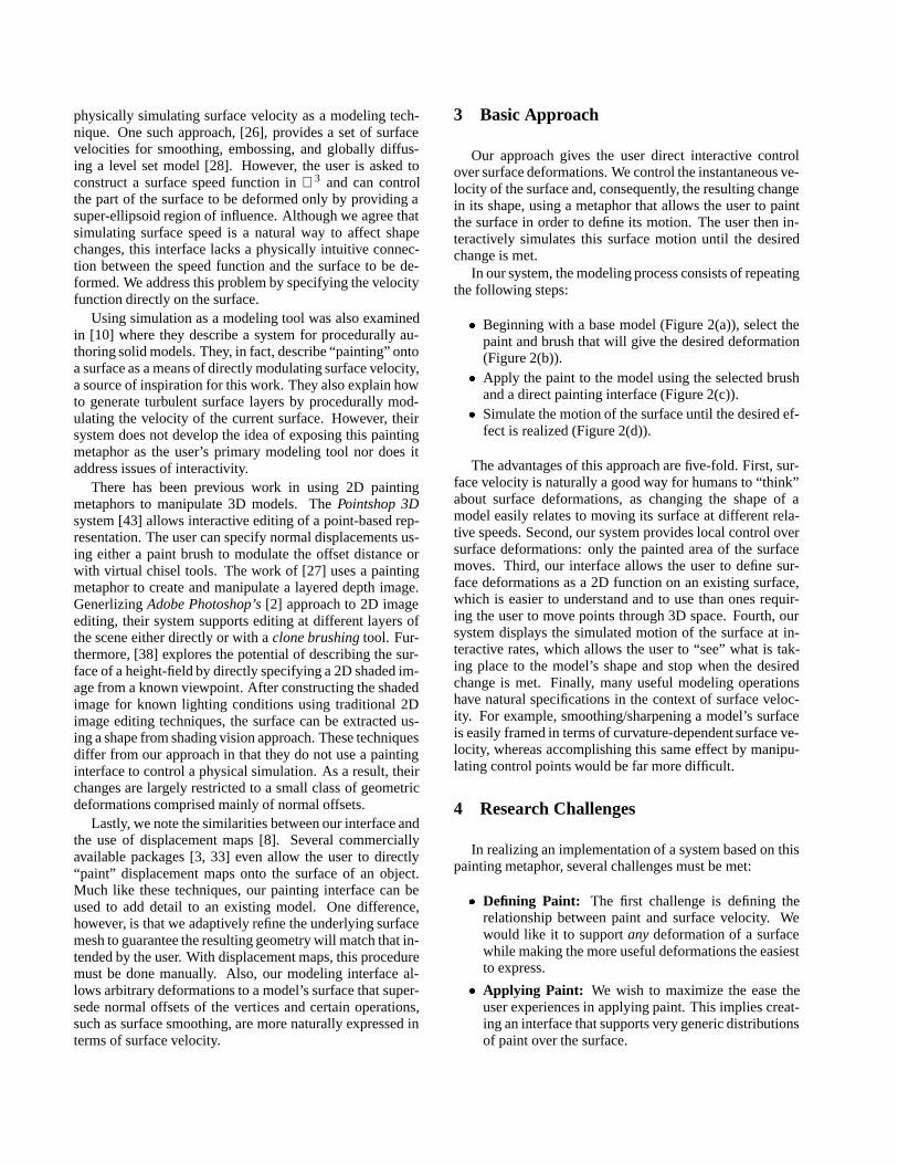
� Stylized Cemetery: (Figure 8) This stylized ceme-tery scene was created quickly with our modeling sys-tem. Starting with a base plane, we first created thetree trunk using positive advective paint and then filledin its crown of branches using brush-dependent refine-ment and more advective paint. The gravestones weregrown off the base plane using a smoothly varyingbrush bitmap of a rectangle that decreased in intensityat its ends. The engravings on the gravestones showhow brush-dependent refinement can create highly de-tailed geometry on an initially simple object. Otherexamples of multi-resolution deformations include thegrassy texture of the ground and the knot in the trunkof the tree.
� Melting Candle: (Figure 9) This candle was createdby first growing its overall shape from a base planeusing advective paint. Next, we added an indenta-tion to its top using negative advective paint. To givethe model a melting look, we added the wax drippingdown its sides by simulating a mixture of propagat-ing and advective paint modulated with a small brushbitmap the user manually moved along the side of thecandle. The pool of wax around the candle’s base was
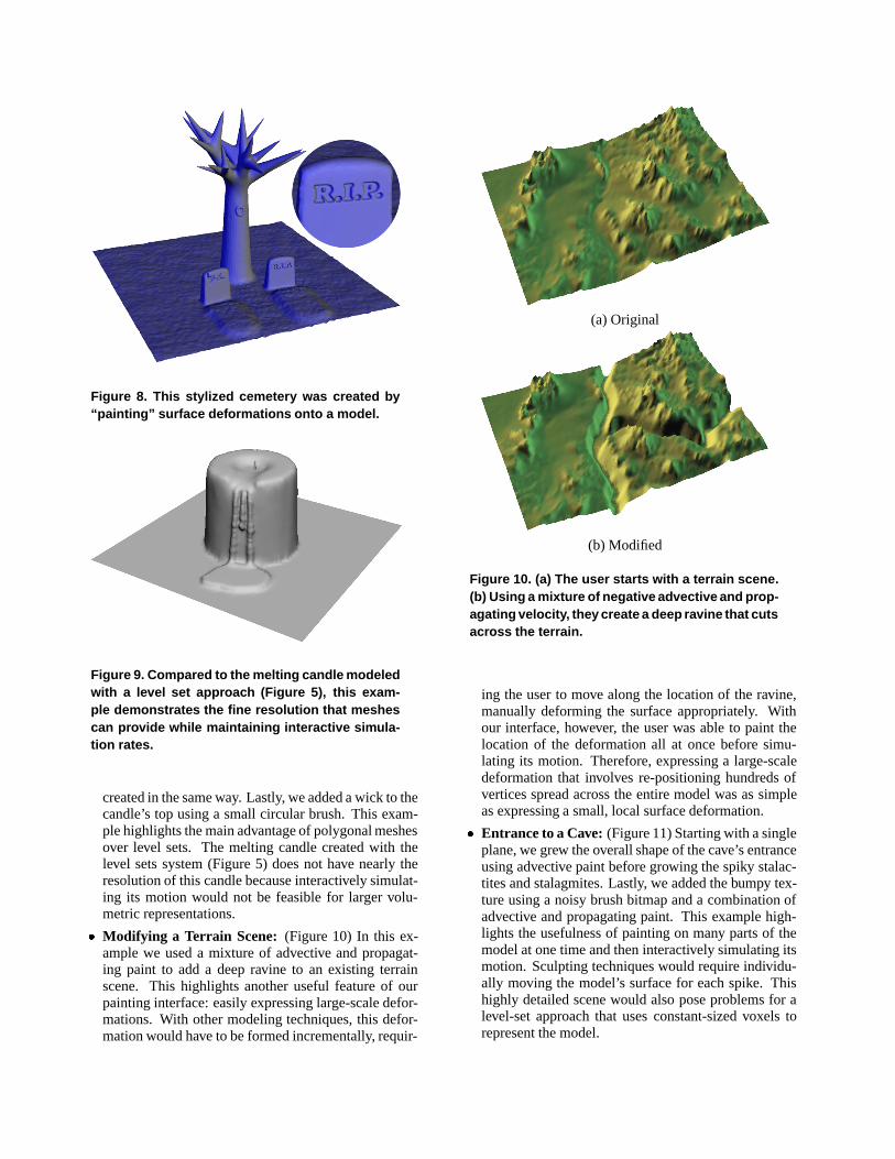
Figure 8. This stylized cemetery was created by“painting” surface deformations onto a model.
Figure 9. Compared to the melting candle modeledwith a level set approach (Figure 5), this exam-ple demonstrates the fine resolution that meshescan provide while maintaining interactive simula-tion rates.
created in the same way. Lastly, we added a wick to thecandle’s top using a small circular brush. This exam-ple highlights the main advantage of polygonal meshesover level sets. The melting candle created with thelevel sets system (Figure 5) does not have nearly theresolution of this candle because interactively simulat-ing its motion would not be feasible for larger volu-metric representations.
� Modifying a Terrain Scene: (Figure 10) In this ex-ample we used a mixture of advective and propagat-ing paint to add a deep ravine to an existing terrainscene. This highlights another useful feature of ourpainting interface: easily expressing large-scale defor-mations. With other modeling techniques, this defor-mation would have to be formed incrementally, requir-
(a) Original
(b) Modified
Figure 10. (a) The user starts with a terrain scene.(b) Using a mixture of negative advective and prop-agating velocity, they create a deep ravine that cutsacross the terrain.
ing the user to move along the location of the ravine,manually deforming the surface appropriately. Withour interface, however, the user was able to paint thelocation of the deformation all at once before simu-lating its motion. Therefore, expressing a large-scaledeformation that involves re-positioning hundreds ofvertices spread across the entire model was as simpleas expressing a small, local surface deformation.
� Entrance to a Cave: (Figure 11) Starting with a singleplane, we grew the overall shape of the cave’s entranceusing advective paint before growing the spiky stalac-tites and stalagmites. Lastly, we added the bumpy tex-ture using a noisy brush bitmap and a combination ofadvective and propagating paint. This example high-lights the usefulness of painting on many parts of themodel at one time and then interactively simulating itsmotion. Sculpting techniques would require individu-ally moving the model’s surface for each spike. Thishighly detailed scene would also pose problems for alevel-set approach that uses constant-sized voxels torepresent the model.
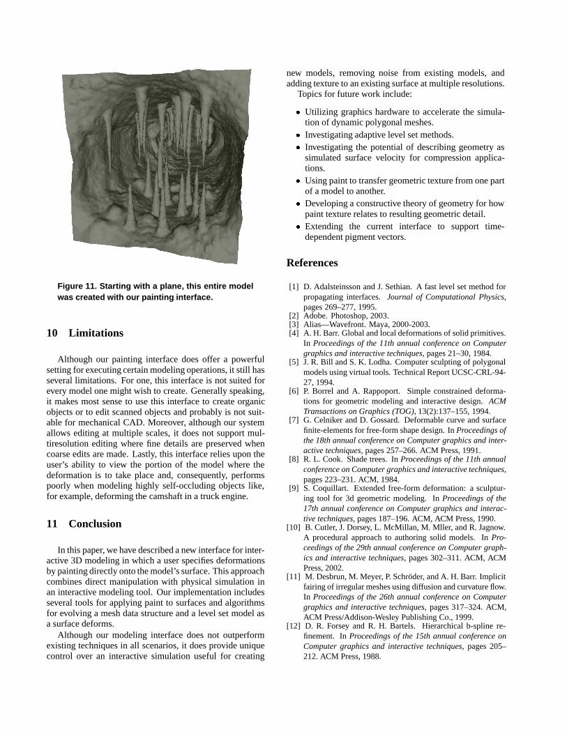
Figure 11. Starting with a plane, this entire modelwas created with our painting interface.
10 Limitations
Although our painting interface does offer a powerfulsetting for executing certain modeling operations, it still hasseveral limitations. For one, this interface is not suited forevery model one might wish to create. Generally speaking,it makes most sense to use this interface to create organicobjects or to edit scanned objects and probably is not suit-able for mechanical CAD. Moreover, although our systemallows editing at multiple scales, it does not support mul-tiresolution editing where fine details are preserved whencoarse edits are made. Lastly, this interface relies upon theuser’s ability to view the portion of the model where thedeformation is to take place and, consequently, performspoorly when modeling highly self-occluding objects like,for example, deforming the camshaft in a truck engine.
11 Conclusion
In this paper, we have described a new interface for inter-active 3D modeling in which a user specifies deformationsby painting directly onto the model’s surface. This approachcombines direct manipulation with physical simulation inan interactive modeling tool. Our implementation includesseveral tools for applying paint to surfaces and algorithmsfor evolving a mesh data structure and a level set model asa surface deforms.
Although our modeling interface does not outperformexisting techniques in all scenarios, it does provide uniquecontrol over an interactive simulation useful for creating
new models, removing noise from existing models, andadding texture to an existing surface at multiple resolutions.
Topics for future work include:
� Utilizing graphics hardware to accelerate the simula-tion of dynamic polygonal meshes.
� Investigating adaptive level set methods.� Investigating the potential of describing geometry as
simulated surface velocity for compression applica-tions.
� Using paint to transfer geometric texture from one partof a model to another.
� Developing a constructive theory of geometry for howpaint texture relates to resulting geometric detail.
� Extending the current interface to support time-dependent pigment vectors.
References
[1] D. Adalsteinsson and J. Sethian. A fast level set method forpropagating interfaces.Journal of Computational Physics,pages 269–277, 1995.
[2] Adobe. Photoshop, 2003.[3] Alias—Wavefront. Maya, 2000-2003.[4] A. H. Barr. Global and local deformations of solid primitives.
In Proceedings of the 11th annual conference on Computergraphics and interactive techniques, pages 21–30, 1984.
[5] J. R. Bill and S. K. Lodha. Computer sculpting of polygonalmodels using virtual tools. Technical Report UCSC-CRL-94-27, 1994.
[6] P. Borrel and A. Rappoport. Simple constrained deforma-tions for geometric modeling and interactive design.ACMTransactions on Graphics (TOG), 13(2):137–155, 1994.
[7] G. Celniker and D. Gossard. Deformable curve and surfacefinite-elements for free-form shape design. InProceedings ofthe 18th annual conference on Computer graphics and inter-active techniques, pages 257–266. ACM Press, 1991.
[8] R. L. Cook. Shade trees. InProceedings of the 11th annualconference on Computer graphics and interactive techniques,pages 223–231. ACM, 1984.
[9] S. Coquillart. Extended free-form deformation: a sculptur-ing tool for 3d geometric modeling. InProceedings of the17th annual conference on Computer graphics and interac-tive techniques, pages 187–196. ACM, ACM Press, 1990.
[10] B. Cutler, J. Dorsey, L. McMillan, M. Mller, and R. Jagnow.A procedural approach to authoring solid models. InPro-ceedings of the 29th annual conference on Computer graph-ics and interactive techniques, pages 302–311. ACM, ACMPress, 2002.
[11] M. Desbrun, M. Meyer, P. Schr¨oder, and A. H. Barr. Implicitfairing of irregular meshes using diffusion and curvature flow.In Proceedings of the 26th annual conference on Computergraphics and interactive techniques, pages 317–324. ACM,ACM Press/Addison-Wesley Publishing Co., 1999.
[12] D. R. Forsey and R. H. Bartels. Hierarchical b-spline re-finement. InProceedings of the 15th annual conference onComputer graphics and interactive techniques, pages 205–212. ACM Press, 1988.

[13] S. F. Frisken, R. N. Perry, A. P. Rockwood, and T. R. Jones.Adaptively sampled distance fields: a general representa-tion of shape for computer graphics. InProceedings of the27th annual conference on Computer graphics and interac-tive techniques, pages 249–254. ACM Press/Addison-WesleyPublishing Co., 2000.
[14] J. Gain. Virtual sculpting: An investigation of directly ma-nipulated free-form deformation in a virtual environment.Msc Thesis, Department of Computer Science, 1996.
[15] T. A. Galyean and J. F. Hughes. Sculpting: an interactive vol-umetric modeling technique. InProceedings of the 18th an-nual conference on Computer graphics and interactive tech-niques, pages 267–274. ACM Press, 1991.
[16] P. Hanrahan and P. Haeberli. Direct wysiwyg painting andtexturing on 3d shapes. InProceedings of the 17th annualconference on Computer graphics and interactive techniques,pages 215–223. ACM, ACM Press, 1990.
[17] W. M. Hsu, J. F. Hughes, and H. Kaufman. Direct manip-ulation of free-form deformations. InProceedings of the19th annual conference on Computer graphics and interac-tive techniques, pages 177–184. ACM, ACM Press, 1992.
[18] T. Igarashi and D. Cosgrove. Adaptive unwrapping for inter-active texture painting. In2001 ACM Symposium on Interac-tive 3D Graphics, pages 209–216. ACM, March 2001.
[19] F. Lazarus, S. Coquillart, and P. Jancene. Axial deforma-tions: an intuitive deformation technique.Computer-AidedDesign, pages 607–613, August 1994.
[20] M. Levoy, K. Pulli, B. Curless, S. Rusinkiewicz, D. Koller,L. Pereira, M. Ginzton, S. Anderson, J. Davis, J. Ginsberg,J. Shade, and D. Fulk. The digital michelangelo project: 3dscanning of large statues. InProceedings of the 27th annualconference on Computer graphics and interactive techniques,pages 131–144. ACM Press/Addison-Wesley Publishing Co.,2000.
[21] W. E. Lorensen. Marching through the visible man. InIEEEVisualization, pages 368–373, 1995.
[22] W. E. Lorensen and H. E. Cline. Marching cubes: A highresolution 3d surface construction algorithm. InProceedingsof the 14th annual conference on Computer graphics and in-teractive techniques, pages 163–169. ACM Press, 1987.
[23] R. MacCracken and K. I. Joy. Free-form deformations withlattices of arbitrary topology. InProceedings of the 23rd an-nual conference on Computer graphics and interactive tech-niques, pages 181–188. ACM Press, 1996.
[24] L. Markosian, J. M. Cohen, T. Crulli, and J. Hughes. Skin:a constructive approach to modeling free-form shapes. InProceedings of the 26th annual conference on Computergraphics and interactive techniques, pages 393–400. ACMPress/Addison-Wesley Publishing Co., 1999.
[25] S. Mizuno, M. Okada, and J. ichiro Toriwaki. Virtual sculpt-ing and virtual woodcut printing.The Visual Computer, pages39–51, 1998.
[26] K. Museth, D. E. Breen, R. T. Whitaker, and A. H. Barr.Level set surface editing operators. InProceedings ofSIGGRAPH 2002, Computer Graphics Proceedings, AnnualConference Series, pages 330–338. ACM, ACM Press / ACMSIGGRAPH, 2002.
[27] B. M. Oh, M. Chen, J. Dorsey, and F. Durand. Image-basedmodeling and photo editing. InProceedings of the 28th an-nual conference on Computer graphics and interactive tech-niques, pages 433–442. ACM Press, 2001.
[28] S. Osher and J. A. Sethian. Fronts propagating withcurvature-dependent speed: Algorithms based on Hamilton-Jacobi formulations. Journal of Computational Physics,79:12–49, 1988.
[29] R. N. Perry and S. F. Frisken. Kizamu: a system for sculptingdigital characters. InProceedings of the 28th annual confer-ence on Computer graphics and interactive techniques, pages47–56. ACM Press, 2001.
[30] L. Piegl. On nurbs: a survey.Computer Graphics and Ap-plications, 11:55–71, 1991.
[31] T. W. Sederberg and S. R. Parry. Free-form deformation ofsolid geometric models. InProceedings of the 13th annualconference on Computer graphics and interactive techniques,pages 151–160. ACM, ACM Press, 1986.
[32] K. Singh and E. Fiume. Wires: a geometric deformationtechnique. InProceedings of the 25th annual conference onComputer graphics and interactive techniques, pages 405–414. ACM Press, 1998.
[33] Softimage. Xsi, 2000-2003.[34] R. Szeliski and D. Tonnesen. Surface modeling with oriented
particle systems.Computer Graphics, 26(2):185–194, 1992.[35] D. Terzopoulos and K. Fleischer. Deformable models.Visual
Computer, pages 306–311, 1988.[36] D. Terzopoulos, J. Platt, A. Barr, and K. Fleischer. Elasti-
cally deformable models. InProceedings of the 14th annualconference on Computer graphics and interactive techniques,pages 205–214. ACM Press, 1987.
[37] D. Terzopoulos and H. Qin. Dynamic nurbs with geometricconstraints for interactive sculpting.ACM Transactions onGraphics (TOG), 13(2):103–136, 1994.
[38] C. van Overveld. Painting gradients: Free-form surface de-sign using shading patterns. In W. A. Davis and R. Bar-tels, editors,Graphics Interface, pages 151–158. CanadianHuman-Computer Communications Society, 1996.
[39] S. W. Wang and A. E. Kaufman. Volume sculpting. InPro-ceedings of the 1995 symposium on Interactive 3D graphics,pages 151–ff. ACM Press, 1995.
[40] J. P. Y. Wong, R. W. H. Lau, and L. Ma. Virtual 3dsculpting.Journal of Visualization and Computer Animation,11(3):155–166, 2000.
[41] D. Zorin and P. Schr¨oder. Eds. course notes: Subdivision formodeling and animation, 1998.
[42] D. Zorin, P. Schr¨oder, and W. Sweldens. Interactive mul-tiresolution mesh editing. InProceedings of the 24th annualconference on Computer graphics and interactive techniques,pages 259–268. ACM Press/Addison-Wesley Publishing Co.,1997.
[43] M. Zwicker, M. Pauly, O. Knoll, and M. Gross. Pointshop3d: an interactive system for point-based surface editing.In Proceedings of the 29th annual conference on Computergraphics and interactive techniques, pages 322–329. ACMPress, 2002.


![MAI Painting Brush: An Interactive Device That …tamura/paper/UIST10_otsuki[1].pdfMAI Painting Brush: An Interactive Device That Realizes the Feeling of Real Painting Mai Otsuki,](https://img.dokumen.tips/doc/110x75/5fe76f2d8055ce45863b04cb/mai-painting-brush-an-interactive-device-that-tamurapaperuist10otsuki1pdf.jpg)