Embed Size (px)
Citation preview

8/6/2019 An Integrated Thin-walled Steel Skeleton Structure (Two Full Scale Tests)
http://slidepdf.com/reader/full/an-integrated-thin-walled-steel-skeleton-structure-two-full-scale-tests 1/10
Journal of Constructional Steel Research 66 (2010) 470–479
Contents lists available at ScienceDirect
Journal of Constructional Steel Research
journal homepage: www.elsevier.com/locate/jcsr
An integrated thin-walled steel skeleton structure (two full scale tests)
Alireza Bagheri Sabbagh a,b,∗, Rasoul Mirghaderi a, Mihail Petkovski b, Kypros Pilakoutas b
a Department of Civil Engineering, University of Tehran, Tehran, Iranb Department of Civil and Structural Engineering, University of Sheffield, Sheffield, UK
a r t i c l e i n f o
Article history:
Received 4 February 2008Accepted 10 October 2009
Keywords:
Thin-walled steel sections
Beam–column connections
Seismic performance
a b s t r a c t
Theincreased popularity of cold-formed thin-walled steel sections in housing construction has lead to an
increasedinterest in thedevelopmentof thin-walled frame buildingsin accordance with seismic require-ments. This paper investigates appropriate details for the main frame elements of a thin-walled building
structure. Some of the proposed details are tested by two full scale one-storey frames under gravity andlateral cyclic loads. The results show that this type of structure offers a good potential for earthquakeresistant construction, but more thorough studies are needed.
© 2009 Elsevier Ltd. All rights reserved.
1. Introduction
Increasing world population and land limitation is leading to
a growing demand for multi storey dwellings. Steel is popular inmulti storey construction due to its high strength and ductility.
However, there are few structural systems that comply with mod-
ern specifications such as cost efficiency, prefabrication, mass pro-
duction, recycling and seismic resistance. Hot-rolled steel sections
have been successfully used for the construction of multi storey
buildings, but their production is costly to the environment anddue to the limited number of section sizes they can be heavy and
inefficient. Cold-formed steel sections are easier to manufacture
and offer a larger variety of sections. This can lead to a more effi-
cient design.
In general Cold-Formed Steel sections (CFS sections) areformed
from thin-walled elements. In the UK and other developed coun-
tries, CFS stud walls have been used for partitions and framing sys-
tems for many years. Stud wall framing systems are available forlow rise as well as multi storey residential buildings in low seis-
micity regions. This system can be used for buildings with up to
four storeys and short spans [1].
In some design manuals the response modification coefficient for
seismic design of stud wall frames with diagonal braces as lateral
load bearing elements is limited to R = 4 [2]. This value is lower
than R = 5 for the hot-rolled steel Ordinary Concentrically Braced
Frames [3]. Frequent local failures in the joints and significantpinching and slackness in cyclic load–deformation loops leads to
∗ Corresponding address: Department of Civil and Structural Engineering,
University of Sheffield, Sir Frederick Mappin Building, Mappin Street, Sheffield, S1
3JD, UK. Tel.: +44 0 114 222 5724; fax: +44 0 114 222 5700.
E-mail address: [email protected](A.B. Sabbagh).
low seismic energy dissipation capacity [4]. In addition, the lackof continuity between adjacent storeys limits the height of the
buildings, particularly in zones with high seismicity.Cold-Formed Steel-Special Bolted Moment Frames (CFS-SBMF)
forms a system that is being developed by the American Iron andSteel Institute (AISI)for onestorey structures in seismic regions [5].
This system is made up of Hollow Structural Sections (HSS) forcolumns and double channel sections for beams. Snug-tight high
strength bolts are used to connect the side passing beams to thecolumn walls [6]. In this new type of thin-walled structure, theseismic energy is dissipated through slippage and local yielding of
the bolts in the connections, which occurs before any yielding ineither beams or columns [6].
This paper describes the development of details for CFS thin-
walled frames for integrated multi storey skeleton buildings. Thebehaviour of the building under gravity and cyclic lateral loads wasinvestigated by tests on two full scale one-storey frames conducted
in BHRC (Building and Housing Research Centre of Iran).
2. Details of integrated thin-walled steel skeleton structures
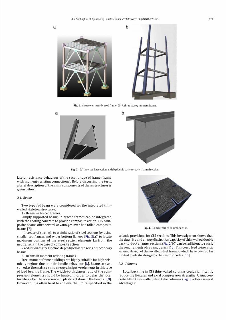
Two types of integrated thin-walled frame were considered: (a)
braced frames and (b) moment frames as shown in Fig. 1(a) and(b).Here, Fig. 1(a) shows a two-storey, one-bay braced frame at thestage of castingof concrete slabs, awaiting to be spliced to the third
storey, whereas Fig. 1(b) shows a three-storey, one-bay momentframe at the stage of placing the beams awaiting to be spliced to
the fourth storey. The use of an integrated structural system isnecessary for the seismic resistance.
In this study two types of specimen A and B were tested.Specimen A was designed to investigate the behaviour of the
members of the first type of frame (but without diagonal braces)under gravity loads. Specimen B was designed to investigate the
0143-974X/$ – see front matter© 2009 Elsevier Ltd. All rights reserved.doi:10.1016/j.jcsr.2009.10.007
8/6/2019 An Integrated Thin-walled Steel Skeleton Structure (Two Full Scale Tests)
http://slidepdf.com/reader/full/an-integrated-thin-walled-steel-skeleton-structure-two-full-scale-tests 2/10
A.B. Sabbagh et al. / Journal of Constructional Steel Research 66 (2010) 470–479 471
Fig. 1. (a) A two storey braced frame; (b) A three storey moment frame.
Fig. 2. (a) Inverted hat section and (b) double back-to-back channel section.
lateral resistance behaviour of the second type of frame (framewith moment-resisting connections). Before discussing the tests,a brief description of the main components of these structures isgiven below.
2.1. Beams
Two types of beam were considered for the integrated thin-walled skeleton structures:
1 - Beams in braced frames.Simply supported beams in braced frames can be integrated
with the roofing concrete to provide composite action. CFS com-
posite beams offer several advantages over hot-rolled compositebeams [7]:
- Increase of strength to weight ratio of steel sections by usingsmaller top flanges and wider bottom flanges (Fig. 2(a)) to locatemaximum portions of the steel section elements far from theneutral axis in the case of composite action.
- Reduction of steel section depth by closerspacing of secondarybeams.
2 - Beams in moment resisting frames.Steel moment frame buildings are highly suitable for high seis-
micity regions due to their ductile behaviour [8]. Beams are as-sumed as the main seismic energydissipative elements in this typeof load bearing frame. The width-to-thickness ratio of the com-pression elements should be limited in order to delay the local
buckling after the occurrence of plastic rotation in the beams [3,9].However, it is often hard to achieve the limits specified in the
Fig. 3. Concrete filled column section.
seismic provisions for CFS sections. This investigation shows thatthe ductility and energy dissipation capacity of thin-walled doubleback-to-back channel sections (Fig. 2(b)) can be sufficient to satisfythe requirements of seismic design [10]. This could lead to inelasticseismic design of thin-walled steel frames, which have been so farlimited to elastic design by the seismic codes [10].
2.2. Columns
Local buckling in CFS thin-walled columns could significantlyreduce the flexural and axial compression strengths. Using con-
crete filled thin-walled steel tube columns (Fig. 3) offers severaladvantages:

8/6/2019 An Integrated Thin-walled Steel Skeleton Structure (Two Full Scale Tests)
http://slidepdf.com/reader/full/an-integrated-thin-walled-steel-skeleton-structure-two-full-scale-tests 3/10
472 A.B. Sabbagh et al. / Journal of Constructional Steel Research 66 (2010) 470–479
Fig. 4. Through-plate beam-to-column connection details (Two views).
– Inward buckling modes in steel walls are prevented, leadingto increase in local buckling stress [11].
– Triaxial stresses produced by confinement action in theconcrete core enhance the ductility and load carrying capacity of the composite column in comparison with bare steel columns [11].
– Concrete filled columns offer inherent fire resistance without
the high costs of fire protection materials [12].– Storey drifts of the moment frame buildings are reduced dueto increased stiffness of the columns [13].
– Beam–column connection elements could be restricted by in-filled concrete to avoid local damage [13].
2.3. Beam–column connections
An appropriate beam–column connection detail is required tomobilize the ductility capacity of the thin-walled moment framebeams.Apartfrom theprevailing local failures,a lack of outof planestiffness is a problem in thin-walled elements.
The transfer of forces by in-plane actions could be achieved bycrossed plates passing through the separated cold-formed sectionsof the beams and the separated sections of the columns (Fig. 4).
In this type of beam–column connection, the beam is strength-ened by the through plate thus avoiding formation of a plastichinge near the face of the column. This is essential to prevent abrittle failure of the connection elements as described in FEMA-350 [9].
The through plate can be welded to all faces of the tubularcolumn section and bolted to the webs of the double back-to-backchannel beam section, as illustrated in Fig. 4. The bolts have to bepositioned at a sufficient distance to provide a sufficient lever armto resist the bending moment from the beam. By connecting thethrough plate to the opposite walls of the column, the couplingforces formed along the length of the column will resist thebending moment from the beam. In this mechanism the out-of-plane actions are limited by mobilizing the in-plane actions in thecolumn walls before any out-of-plane actions can be activated.
2.4. Brace connections
The transfer of forces by in-plane actions can be achieved bythrough plates passing through the separated cold-formedsectionsof the columns, beams and the separated sections of diagonalbraces (Fig. 5).
2.5. Flooring components
Theflooringcomponents canbe similar to those in conventionalcomposite floors:
– CFS joists placed at regular distances between the mainbeams;
– Topping concrete to provide diaphragm action, sound insula-tion and fire protection;
Table 1
Tests carried out for the specimens.
Specimen Tests Loading
A A-1 Service gravity load
A-2 Lateral cyclic load
A-3 Ultimate gravity load
B B-1 Service gravity loadB-2 Lateral cyclic load
– Shear connectors to resist slippage between the steel sectionsand the top concrete;
– Corrugated sheets to make a working platform and formingfor concrete casting;
– Steel mesh reinforcement to limit temperature-inducedcracking.
Twospecimens were designed to testsome of theabovecompo-nentsand details: specimen A, to test a frame mainly undergravityloads; and specimen B, to test a frame mainly under lateral cyclicloads. The two test specimens are described as below.
3. Test specimens
Using thin-walled elements (such as those introduced inSection 2) in a skeleton frame requires a thorough investigationof the actual performance of the structure and development of efficient details. Considering that this investigation was an earlystep of a larger study, the details used for a one-storey test framewere still in the concept stage. Two specimens (A and B), withdifferent element sections and connection details, were used in thetests. Specimen A was an unbraced frame with simply supportedconnections used to test the main structural elements (beams,columns and joists) under gravityloads. A lateral cyclicloading testwas carried out as an additional test for this specimen.
Specimen B was a moment frame with moment resisting con-nections designed to investigate the seismic performance of this
type of frame under lateral cyclic loads. The tests carried out onthese specimens are listed in Table 1. The height and span dimen-sions, the cross section sizes and the locations of the members of these specimens are shown in Fig. 6.
The design of the elements of the specimens was based onAllowable Strength Design (ASD) method given in the Cold FormedSteel Design Manual [14] and Specification for Structural SteelBuildings [15].
3.1. Specimen A
For this specimen, inverted hat sections were used for thebeams and joists, and tube sections for the columns (see Fig. 6).The reason for this choice of section was to create a frame with the
sections filled with concrete at the same time when the concretewas cast on the corrugated sheets of the roof. The restraining effect

8/6/2019 An Integrated Thin-walled Steel Skeleton Structure (Two Full Scale Tests)
http://slidepdf.com/reader/full/an-integrated-thin-walled-steel-skeleton-structure-two-full-scale-tests 4/10
A.B. Sabbagh et al. / Journal of Constructional Steel Research 66 (2010) 470–479 473
Fig. 5. Brace connections to: (a) the base plate, and (b) beam.
6 0
2
20
1 0 0
2
2
2 0
25
30
30
2 2 0
2 1 0
3 0 3
0
3 0
3
3
80 70 2 2
80°
8 0
°
80°
1 1 0
°
40
30
100 180
1 8 0
70
1 5 0
1 5 0
Fig. 6. Specimens A and B: dimensions, member locations and cross section sizes.
Fig. 7. (a) Assembled members; (b) specimen with roof.
of theconcretecan limit thebuckling deformations andprevent theprevailing local failures typical for thin-walled elements. The beams were connected to the columns through simple-support type connections with no theoretical moment resistance.

8/6/2019 An Integrated Thin-walled Steel Skeleton Structure (Two Full Scale Tests)
http://slidepdf.com/reader/full/an-integrated-thin-walled-steel-skeleton-structure-two-full-scale-tests 5/10
474 A.B. Sabbagh et al. / Journal of Constructional Steel Research 66 (2010) 470–479
Fig. 8. Beam–column connections for B1 and B2 beams: (a) assembled and (b) ready for test.
D T
D T
D T
D T
DT
SG
SG
SG
SG
S G
a b
DT
Fig. 9. (a) Instrumentation positions and (b) displacement transducers under the beams.
The specimen was designed only for gravity loads, so there was nodiagonal bracing for lateral resistance.
The elements were designed for a combination of dead and liveloads at two stages: (1) before and (2) after concrete hardening.The loads are: the concrete on top and inside the beams and joistsof the roof (for stages 1 and 2), additional common dead and liveloads for residential buildings (for stage 2). The total load taken inthe design was 2 kN/m2 for the 1st stage and is 5 kN/m2 for the2nd stage.
3.2. Specimen B
Two major changes were introduced for this specimen: (i)the inverted hat sections of the beams were replaced with twoconnected back-to-back channel sections (B1) and (ii) the simple-support connections were replaced by moment-resistant connec-tions for B1 beams (Fig. 6).
The assembled beams and columns and the roof concrete, castover the corrugated sheets are shown in Fig. 7(a) and (b), respec-tively. The beam–column connections, moment-resisting for B1beams and simply supported for B2 beams are shown in Fig. 8(a)(when assembled) and Fig. 8(b) (complete with roof and ready fortesting). In the moment resisting connections, the through plate isstiffened to avoid buckling of the plate.
Specimen B was designed for both gravity loads and seismicloads, using the Iranian seismic codes [16]. The gravity loadswere considered in two stages: (1) before and (2) after concretehardening, as in the case of specimen A.
3.3. Instrumentation
The instrumentation positions for specimens A and B, for both
gravity and lateral loading tests, are shown in Fig. 9. The straingauges (SG) were located at mid-span of the beams and joists,
under their bottom flanges, and at the base, mid-height and top of the columns (on allsides). The displacement transducers (DT) were
positioned (i) at mid-span of the beams (Fig. 9(b)) and joists, forthe gravity loading test, and (ii) horizontally, at the roof level, mid-height and the base of the columns, for thelateral loading tests. ForSpecimen B two strain gauges were added at the ends of B1 beamflanges.
4. Tests
The tests conducted on specimens A and B (A-1, A-2, A-3, B-1and B-2, listed in Table 1) are described below.
4.1. Specimen A: Gravity loading test (A-1)
In this test the specimen was subjected to a uniform gravityload on the roof, applied by adding blocks in 8 steps of 20 kN,
up to 160 kN (Fig. 10). The last step, the load 160 kN (10 kN/m2
)was twice the expected allowable design load. During this gravityloading test there was no evidence of either local or globalbuckling.
The strain results for the columns in different loading stepsare shown in Fig. 11. The test results were compared with thepredicted results for columns with fully composite action andcolumns with no composite action. The graphs in Fig. 11 showthat the actual results are between these two assumptions, whichsuggest a partial composite action of the columns in the test as aresult of probable slippage between the steel section and in-filledconcrete.
4.2. Specimen A: Lateral loading test (A-2)
The beam–column connections of this specimen were simplysupported seated type connections with no theoretical bending
8/6/2019 An Integrated Thin-walled Steel Skeleton Structure (Two Full Scale Tests)
http://slidepdf.com/reader/full/an-integrated-thin-walled-steel-skeleton-structure-two-full-scale-tests 6/10
A.B. Sabbagh et al. / Journal of Constructional Steel Research 66 (2010) 470–479 475
Fig. 10. Uniform gravity loading on the roof.
140
120
100
80
60
40
20
00 50 100 150 200
L o a d ( k N )
Strainx106
test result
Fully composite action
No composite action
Fig. 11. Strains measured in the test and predicted for the columns.
moment resistance. However, in order to investigate a possiblesemi-rigid action, the specimen was tested under lateral load. The
semi-rigid action, in this case, was a result of integration of the
through plates connected to all sides of the column and embeddedinside the filled concrete of the beams and the columns.
The cyclic lateral load was applied statically by two hydraulic
actuators at both sides of the roof and distributed by steel pro-files, as shown in Fig. 12. During the lateral loading test, the gra-
vity load applied on the roof was 5 kN/m2 (including the roof
weight), equal to the allowable gravity load [14,15]. The lateralload was applied as cyclic, progressively increasing through the
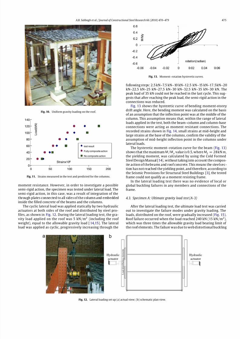
Fig. 13. Moment–rotation hysteretic curves.
following steps: 2.5 kN–7.5 kN–10 kN–12.5 kN–15 kN–17.5kN–20kN–22.5 kN–25 kN–27.5 kN–30 kN–32.5 kN–35 kN–30 kN. Thepeak load of 35 kN could not be reached in the last cycle. This sug-
gests that after reaching the peak load, the semi-rigid action in theconnections was reduced.
Fig. 13 shows the hysteretic curve of bending moment-storeydrift angle. Here, the bending moment was calculated on the basis
of an assumption that the inflection point was at the middle of the
column. This assumption means that, within the range of lateralloads applied in the test, both the beam–column and column-baseconnections were acting as moment resistant connections. The
recorded strains shown in Fig. 14, small strains at mid-height andlarge strains at the base of the columns, confirm the validity of theassumption of mid-height inflection point in the columns underlateral loads.
The hysteretic moment–rotation curve for the beam (Fig. 13)shows that the maximum M/M y value is 0.5, where M y = 28kN m,the yielding moment, was calculated by using the Cold FormedSteel Design Manual [14], without taking into account the compos-
ite action of thebeams and roof concrete. This means the steelsec-tion has not reached the yielding point, and therefore, according tothe Seismic Provisions for Structural Steel Buildings [3], the tested
frame could not qualify as a moment resisting frame.In the lateral loading test there was no evidence of local orglobal buckling failures in any members and connections of theframe.
4.3. Specimen A: Ultimate gravity load test (A-3)
After the lateral loading test, the ultimate load test was carriedout to investigate the failure modes under gravity loading. The
loads, distributed on the roof, were gradually increased (Fig. 15).Roof failure occurred when the load reached 240 kN (15 kN/m2),which was three times the allowable gravity load bearing limit of the roof elements. The failure was due to web distortional buckling
ab
Hydraulic
actuator
Hydraulic
actuator
L o a d d i s t r i b u t i n g e l e m e n t s
Fig. 12. Lateral loading set up (a) actual view; (b) schematic plan view.

8/6/2019 An Integrated Thin-walled Steel Skeleton Structure (Two Full Scale Tests)
http://slidepdf.com/reader/full/an-integrated-thin-walled-steel-skeleton-structure-two-full-scale-tests 7/10
476 A.B. Sabbagh et al. / Journal of Constructional Steel Research 66 (2010) 470–479
Fig. 14. Strain values in column: (a) mid-height and (b) base.
Fig. 15. Ultimate gravity loading with basket blocks (two steps).
Fig. 16. (a) A top view of a roof joist after failure (concrete and corrugated sheet removed to show the deformed joist); (b) A side view of a deep crack in concrete inside the
joists (part of the joist section removed to show the concrete inside).
Fig. 17. Web buckling in joists.
of the joists at mid-span (Fig. 16). Fig. 16(a) shows a view of a roof joist after failure (theroof concrete andcorrugated sheet have been
removed in order to show the deformed joist). Fig. 16(b) shows adeep vertical crack in the concrete inside the joists (the web of the
joist was removed to show the crack in the concrete). Fig. 17 is adrawing showing the buckling failure of the joist web.
It could be assumed that this failure occurred after the failure
of the composite action between the joists and concrete. Stressredistribution could have caused the separation of the webs with
outward inclination, leading to distortional buckling. For beams
with inward inclined webs, this deformation would have beenrestricted by the inside concrete.
4.4. Specimen B: Gravity loading test (B-1)
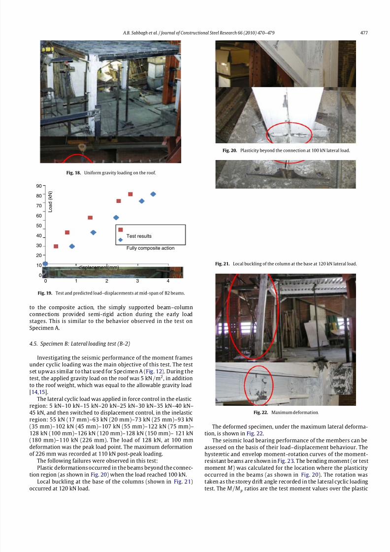
As in thetests of Specimen A, heavy blocks (Fig. 18) were added
gradually on the roof until a total of 5 kN/m2 was reached. Thisload was equal to the allowable design gravity loading in addition
to the self weight of the roof.
Duringthis testtherewas no evidence of failure in anymembersor connection elements.
Fig. 19 shows the load–displacement results for the mid-span
of B2 beams, compared with the predicted values which were
calculated by assuming fully composite action for the beams. The
graphs show that the displacements measured in the test werebelow the predicted values. This could mean that in addition
8/6/2019 An Integrated Thin-walled Steel Skeleton Structure (Two Full Scale Tests)
http://slidepdf.com/reader/full/an-integrated-thin-walled-steel-skeleton-structure-two-full-scale-tests 8/10
A.B. Sabbagh et al. / Journal of Constructional Steel Research 66 (2010) 470–479 477
Fig. 18. Uniform gravity loading on the roof.
90
80
70
60
50
40
30
20
10
00 1 2 3 4
L o a d
( k N )
displacement(mm)
Test results
Fully composite action
Fig. 19. Test and predicted load–displacements at mid-span of B2 beams.
to the composite action, the simply supported beam–column
connections provided semi-rigid action during the early load
stages. This is similar to the behavior observed in the test on
Specimen A.
4.5. Specimen B: Lateral loading test (B-2)
Investigating the seismic performance of the moment framesunder cyclic loading was the main objective of this test. The test
set upwas similar to that used for Specimen A (Fig. 12). During the
test, the applied gravity load on the roof was 5 kN/m2, in addition
to the roof weight, which was equal to the allowable gravity load[14,15].
The lateral cyclic load was applied in force control in the elasticregion: 5 kN–10 kN–15 kN–20 kN–25 kN–30 kN–35 kN–40 kN–
45 kN, and then switched to displacement control, in the inelastic
region: 55 kN (17 mm)–63 kN (20 mm)–73 kN (25 mm)–93 kN
(35 mm)–102 kN (45 mm)–107 kN (55 mm)–122 kN (75 mm)–
128 kN (100 mm)–126 kN (120 mm)–128 kN (150 mm)– 121 kN(180 mm)–110 kN (226 mm). The load of 128 kN, at 100 mm
deformation was the peak load point. The maximum deformation
of 226 mm was recorded at 110 kN post-peak loading.
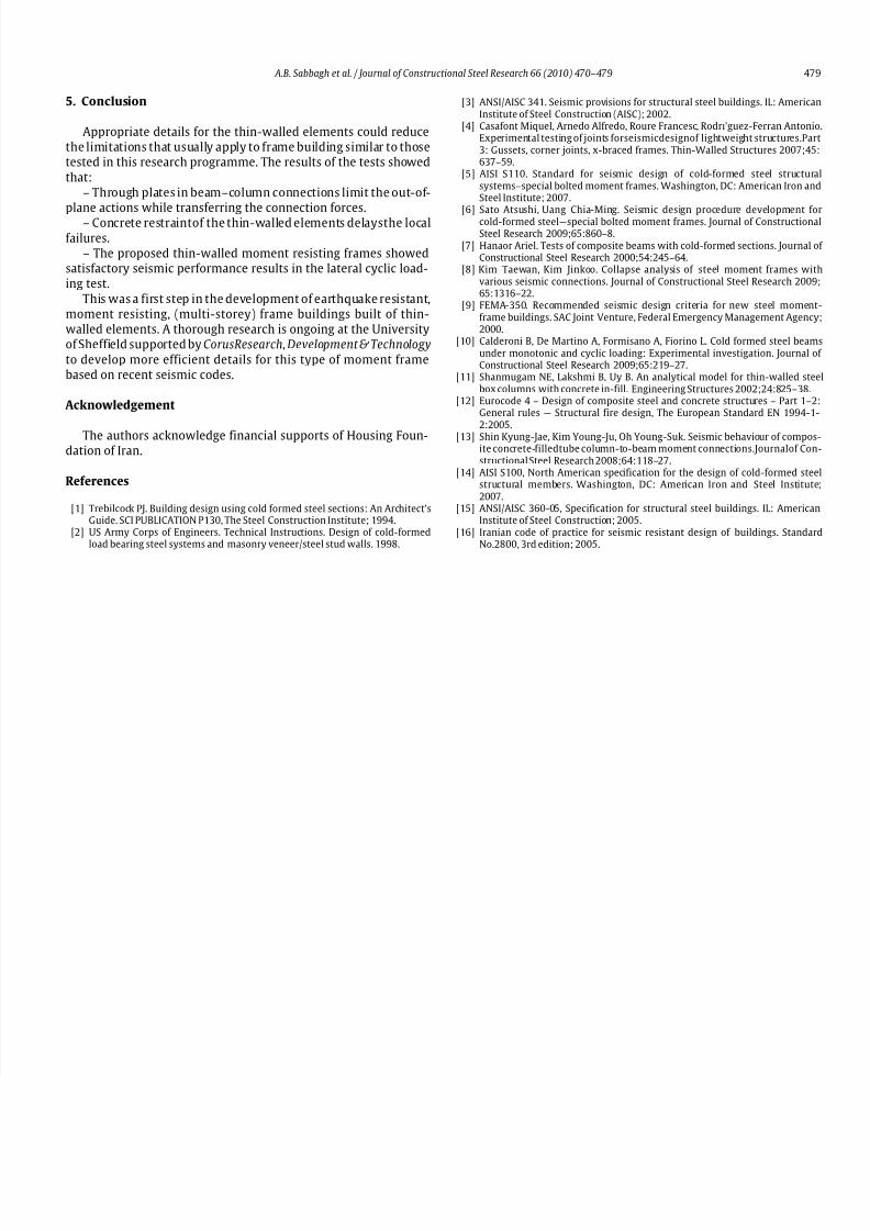
The following failures were observed in this test:
Plastic deformations occurred in the beams beyond the connec-
tion region (as shown in Fig. 20) when the load reached 100 kN.
Local buckling at the base of the columns (shown in Fig. 21)occurred at 120 kN load.
Fig. 20. Plasticity beyond the connection at 100 kN lateral load.
Fig. 21. Local buckling of the column at the base at 120 kN lateral load.
Fig. 22. Maximum deformation.
The deformed specimen, under the maximum lateral deforma-tion, is shown in Fig. 22.
The seismic load bearing performance of the members can be
assessed on the basis of their load–displacement behaviour. The
hysteretic and envelop moment–rotation curves of the moment-resistant beams are shown in Fig. 23. The bending moment (or test
moment M) was calculated for the location where the plasticity
occurred in the beams (as shown in Fig. 20). The rotation was
taken as the storey drift angle recorded in the lateral cyclic loadingtest. The M/M p ratios are the test moment values over the plastic

8/6/2019 An Integrated Thin-walled Steel Skeleton Structure (Two Full Scale Tests)
http://slidepdf.com/reader/full/an-integrated-thin-walled-steel-skeleton-structure-two-full-scale-tests 9/10
478 A.B. Sabbagh et al. / Journal of Constructional Steel Research 66 (2010) 470–479
2
1
0
-1
-0.1 -0.05 0.05 0.1-2
M / M p
M / M p
a b
0
Rotation(radian) Rotation(radian)
2
1.5
1
0.5
00 0.02 0.04 0.06 0.08
Fig. 23. (a) Hysteretic moment–rotation curve and (b) Envelope moment–rotation curve of B1 beams.
Fig. 24. Strain values (a) at the middle and (b) the base of the columns.
Fig. 25. Strain values of (a) mid-span and (b) end of the beams at the bottom flanges.
moment of B1 beams, calculated without taking into account anycomposite action with the roof slab concrete. The value of M p =
21 kNm was calculated by using the Specification for Structural
Steel Buildings [15]. The test moment M was calculated from theapplied lateral loads assuming inflection points at the mid-height
of the columns and mid-span of the beams. This is considered to be
reasonable since the recorded strain values at the inflection pointsof the columns and beams were low in comparison with the strain
values recorded at the base of the columns and the ends of the
beams (Figs. 24 and 25).
The peak values of M/M p in moment–rotation curve shown in
Fig. 23 are significantly higher than 1.0. This could be due to strainhardening of the steel sections andincreased strength of the beams
due to partially composite action, in two out of four connectionswhere the concrete was in compression under lateral cyclic load.
According to the requirements for seismic resistant momentframes [3], the moment–rotation curve is expected to satisfy the
minimum rotation of: (i) 0.02 radian for Intermediate MomentFrames or,(ii) 0.04 radianfor Special MomentFrames, while the re-
sisting moment is 80% of the plasticmoment. Further investigationbased on the seismic provisions [3] could give more precise results.
In this test it was observed that:
– The prevailing local and out-of-plane failures of the thin-walled elements could be limited when appropriately detailed and
sufficiently restrained. This could increase the ductility of thin-walled structures which has been so far expected to be low.
8/6/2019 An Integrated Thin-walled Steel Skeleton Structure (Two Full Scale Tests)
http://slidepdf.com/reader/full/an-integrated-thin-walled-steel-skeleton-structure-two-full-scale-tests 10/10
A.B. Sabbagh et al. / Journal of Constructional Steel Research 66 (2010) 470–479 479
5. Conclusion
Appropriate details for the thin-walled elements could reducethe limitations that usually apply to frame building similar to thosetested in this research programme. The results of the tests showed
that:– Through plates in beam–column connections limit the out-of-
plane actions while transferring the connection forces.– Concrete restraintof the thin-walled elements delaysthe local
failures.– The proposed thin-walled moment resisting frames showed
satisfactory seismic performance results in the lateral cyclic load-ing test.
This was a first step in the development of earthquake resistant,moment resisting, (multi-storey) frame buildings built of thin-walled elements. A thorough research is ongoing at the Universityof Sheffield supported by CorusResearch, Development & Technology
to develop more efficient details for this type of moment framebased on recent seismic codes.
Acknowledgement
The authors acknowledge financial supports of Housing Foun-dation of Iran.
References
[1] Trebilcock PJ. Building design using cold formed steel sections: An Architect’sGuide. SCI PUBLICATION P130, The Steel Construction Institute; 1994.
[2] US Army Corps of Engineers. Technical Instructions. Design of cold-formedload bearing steel systems and masonry veneer/steel stud walls. 1998.
[3] ANSI/AISC 341. Seismic provisions for structural steel buildings. IL: AmericanInstitute of Steel Construction (AISC); 2002.
[4] Casafont Miquel, Arnedo Alfredo, Roure Francesc, Rodrı’guez-Ferran Antonio.Experimental testing of joints forseismicdesignof lightweight structures.Part3: Gussets, corner joints, x-braced frames. Thin-Walled Structures 2007;45:637–59.
[5] AISI S110. Standard for seismic design of cold-formed steel structuralsystems–special bolted moment frames. Washington, DC: American Iron andSteel Institute; 2007.
[6] Sato Atsushi, Uang Chia-Ming. Seismic design procedure development forcold-formed steel—special bolted moment frames. Journal of ConstructionalSteel Research 2009;65:860–8.
[7] Hanaor Ariel. Tests of composite beams with cold-formed sections. Journal of Constructional Steel Research 2000;54:245–64.
[8] Kim Taewan, Kim Jinkoo. Collapse analysis of steel moment frames withvarious seismic connections. Journal of Constructional Steel Research 2009;65:1316–22.
[9] FEMA-350. Recommended seismic design criteria for new steel moment-frame buildings. SAC Joint Venture, Federal Emergency Management Agency;2000.
[10] Calderoni B, De Martino A, Formisano A, Fiorino L. Cold formed steel beamsunder monotonic and cyclic loading: Experimental investigation. Journal of Constructional Steel Research 2009;65:219–27.
[11] Shanmugam NE, Lakshmi B, Uy B. An analytical model for thin-walled steelbox columns with concrete in-fill. Engineering Structures 2002;24:825–38.
[12] Eurocode 4 – Design of composite steel and concrete structures – Part 1–2:General rules — Structural fire design, The European Standard EN 1994-1-2:2005.
[13] Shin Kyung-Jae, Kim Young-Ju, Oh Young-Suk. Seismic behaviour of compos-ite concrete-filledtube column-to-beam moment connections.Journalof Con-structional Steel Research 2008;64:118–27.
[14] AISI S100, North American specification for the design of cold-formed steelstructural members. Washington, DC: American Iron and Steel Institute;2007.
[15] ANSI/AISC 360-05, Specification for structural steel buildings. IL: AmericanInstitute of Steel Construction; 2005.
[16] Iranian code of practice for seismic resistant design of buildings. StandardNo.2800, 3rd edition; 2005.