Embed Size (px)
Citation preview

December 2020
NASA/SP-8007-2020/REV 2
Buckling of Thin-Walled Circular Cylinders
September 1965
August 1968 – first revision
November 2020 – second revision

NASA STI Program Report Series
Since its founding, NASA has been dedicated to the
advancement of aeronautics and space science. The
NASA scientific and technical information (STI)
program plays a key part in helping NASA maintain
this important role.
The NASA STI program operates under the auspices
of the Agency Chief Information Officer. It collects,
organizes, provides for archiving, and disseminates
NASA’s STI. The NASA STI program provides access
to the NTRS Registered and its public interface, the
NASA Technical Reports Server, thus providing one
of the largest collections of aeronautical and space
science STI in the world. Results are published in both
non-NASA channels and by NASA in the NASA STI
Report Series, which includes the following report
types:
• TECHNICAL PUBLICATION. Reports of
completed research or a major significant phase of
research that present the results of NASA
Programs and include extensive data or theoretical
analysis. Includes compilations of significant
scientific and technical data and information
deemed to be of continuing reference value.
NASA counterpart of peer-reviewed formal
professional papers but has less stringent
limitations on manuscript length and extent of
graphic presentations.
• TECHNICAL MEMORANDUM.
Scientific and technical findings that are
preliminary or of specialized interest,
e.g., quick release reports, working
papers, and bibliographies that contain minimal
annotation. Does not contain extensive analysis.
• CONTRACTOR REPORT. Scientific and
technical findings by NASA-sponsored
contractors and grantees.
• CONFERENCE PUBLICATION.
Collected papers from scientific and technical
conferences, symposia, seminars, or other
meetings sponsored or
co-sponsored by NASA.
• SPECIAL PUBLICATION. Scientific,
technical, or historical information from NASA
programs, projects, and missions, often
concerned with subjects having substantial
public interest.
• TECHNICAL TRANSLATION.
English-language translations of foreign
scientific and technical material pertinent to
NASA’s mission.
Specialized services also include organizing
and publishing research results, distributing
specialized research announcements and feeds,
providing information desk and personal search
support, and enabling data exchange services.
For more information about the NASA STI program,
see the following:
• Access the NASA STI program home page at
http://www.sti.nasa.gov
• Help desk contact information:
https://www.sti.nasa.gov/sti-contact-form/
and select the “General” help request type.

National Aeronautics and
Space Administration
Langley Research Center
Hampton, Virginia 23681-2199
December 2020
NASA/SP-8007-2020/REV 2
Buckling of Thin-Walled Circular Cylinders
September 1965
August 1968 – first revision
November 2020 – second revision

Available from:
NASA STI Program / Mail Stop 148
NASA Langley Research Center
Hampton, VA 23681-2199
Fax: 757-864-6500
The use of trademarks or names of manufacturers in the report is for accurate reporting and does not
constitute an official endorsement, either expressed or implied, of such products or manufacturers by the
National Aeronautics and Space Administration.

iii
Foreword From 1964 to 1979, NASA developed uniform criteria for the design of space vehicles in the four
following technology areas:
Chemical Propulsion
Environment
Guidance and Control
Structures
Individual topics within these technology areas were published in a series of NASA Space Vehicle
Design Criteria monographs, the NASA SP-8000 document series. A total of 44 NASA design
criteria monographs on Structures were developed and include four monographs on the design of
buckling-critical structures:
NASA SP-8007: Buckling of Thin-Walled Circular Cylinders, Revised August 1968
NASA SP-8019: Buckling of Thin-Walled Truncated Cones, September 1968
NASA SP-8032: Buckling of Thin-Walled Doubly Curved Shells, August 1969
NASA SP-8068: Buckling Strength of Structural Plates, June 1971
These monographs are known throughout the aerospace industry and provide recommendations
for the design of buckling-critical thin unstiffened plates and shells subjected to various
combinations of mechanical and pressure loads. In addition to these NASA monographs, two
prominent NASA reports were published and are commonly used in the design of stiffened
cylinders:
NASA TN D-5561: Buckling of Stiffened Cylinders in Axial Compression and Bending – A
Review of Test Data, 1969
NASA CR-124075: Isogrid Design Handbook, 1973
Recent industry and NASA experience with the development of launch vehicle structures have
indicated a need for updated monographs for the design of buckling-critical structures that account
for state-of-the-art structural configurations, material systems, and computational tools. This
monograph provides an update to NASA SP-8007 and was prepared under the cognizance of the
NASA Engineering and Safety Center (NESC). It summarizes all significant knowledge and
experience accumulated from the NESC Shell Buckling Knockdown Factor (SBKF) Assessment
(NESC Assessment #: 07-010-E) to date for use in the design of buckling-critical thin-walled
circular cylinders. The lead of the SBKF Assessment and author for this update was Dr. Mark W.
Hilburger of NASA Langley Research Center.
A number of other individuals assisted in developing the material and reviewing the drafts. Mr.
Kenneth Hamm, Ames Research Center, coordinated the completion of this monograph. In
particular, significant contributions were provided by Dr. Robert P. Thornburgh (Army Research
Laboratory); Dr. Vinay Goyal, Mr. Pavel Babuska, and Mr. Matthew R. Keough (The Aerospace
Corporation); Dr. James Smith and Mr. Kauser Imtiaz (Johnson Space Center); and Dr. Mark
Schultz (Langley Research Center).
The format and terminology used in this monograph is similar to previous versions of NASA SP-
8007 for ease of understanding and implementation. In addition, as with the design
recommendations contained in the previous versions of NASA SP-8007, this monograph is to be
regarded as a guideline to design and not as a NASA requirement, unless specified in formal

iv
program requirements. Furthermore, it is expected that the guidelines presented in this monograph
will be updated as appropriate. Designers are advised to stay abreast of updates in the state-of-the-
art and corresponding design criteria. Comments and recommendations on the technical content
contained herein are invited and should be forwarded to the attention of the Center Chief Engineer,
NASA Langley Research Center, Hampton, Virginia, 23681.
November 2020

v
Table of Contents
1.0 Introduction ......................................................................................................................... 1 2.0 State of the Art .................................................................................................................... 3
2.1 Brief History of Early Shell Buckling Research and NASA Design Criteria ................................... 4 2.2 Factors Influencing the Buckling of Thin-Walled Cylinders ............................................................ 6
Geometric Imperfections .................................................................................................... 6 Prebuckling Deformations and Stresses .............................................................................. 7 Boundary Conditions and Nonuniform Loading ................................................................ 8
2.3 Effects of Design Concepts and Features on the Buckling of Thin-Walled Cylinders ..................... 9 Stiffened Isotropic Cylinders .............................................................................................. 9 Composite Cylinders ......................................................................................................... 10 Cutouts .............................................................................................................................. 12 Joints ................................................................................................................................. 12
2.4 Analysis Methods ............................................................................................................................ 13 2.5 Design Approaches ......................................................................................................................... 15
Traditional Empirical Design Approach ........................................................................... 16 Semi-Empirical Design Approach .................................................................................... 17 Analysis-based Design Approach ..................................................................................... 17 Other Methods and Trends................................................................................................ 18
3.0 Criteria .............................................................................................................................. 20 4.0 Recommended Practices ................................................................................................... 21
4.1 Empirical Design Approach ............................................................................................................ 22 Isotropic Unstiffened Cylinders ........................................................................................ 22
Axial Compression ........................................................................................................... 22 Bending ............................................................................................................................. 25 External Pressure .............................................................................................................. 26 Torsion .............................................................................................................................. 29 Combined Loads ............................................................................................................... 31
Orthotropic Cylinders ....................................................................................................... 34 Axial Compression ........................................................................................................... 34 Bending ............................................................................................................................. 36 External Pressure .............................................................................................................. 37 Torsion .............................................................................................................................. 38 Combined Loads ............................................................................................................... 38 Elastic Constants ............................................................................................................... 39 Other Design Considerations in Stiffened Cylinders ........................................................ 44
Isotropic Sandwich Cylinders ........................................................................................... 44 Axial Compression ........................................................................................................... 46 Bending ............................................................................................................................. 49 Lateral Pressure ................................................................................................................. 50 Torsion .............................................................................................................................. 51
Cylinders with an Elastic Core ......................................................................................... 52 Axial Compression ........................................................................................................... 52 External Pressure .............................................................................................................. 53 Torsion .............................................................................................................................. 55 Combined Axial Compression and External Pressure ...................................................... 56
Other Design Considerations ............................................................................................ 57 Joints ................................................................................................................................. 57 Cutouts .............................................................................................................................. 57 Design of Ring Frames ..................................................................................................... 58

vi
4.2 Semi-Empirical Design Approach .................................................................................................. 58 4.3 Analysis-Based Design Approach .................................................................................................. 60
Model Development ......................................................................................................... 61 Overview ........................................................................................................................... 61 Structural Idealization ....................................................................................................... 61 Discretization .................................................................................................................... 62 Material Properties ............................................................................................................ 63 Boundary Conditions ........................................................................................................ 63 Loading Conditions ........................................................................................................... 64 Initial Imperfections and Loading Nonuniformities ......................................................... 64 Analysis Approach ............................................................................................................ 69 Special Considerations for Composite Cylinders ............................................................. 70
Model Validation .............................................................................................................. 71 Knockdown Factor Development Approach..................................................................... 73
Development Approach .................................................................................................... 73 Implementation Example .................................................................................................. 74 Summary of the Approach ................................................................................................ 76 Example Application ........................................................................................................ 76
5.0 References ......................................................................................................................... 78
vii
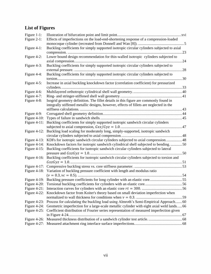
List of Figures
Figure 1-1: Illustration of bifurcation point and limit point. .................................................................. xvi
Figure 2-1: Effects of imperfections on the load-end-shortening response of a compression-loaded
monocoque cylinder (recreated from Donnell and Wan [8]). ................................................ 5
Figure 4-1: Buckling coefficients for simply supported isotropic circular cylinders subjected to axial
compression. ........................................................................................................................ 23
Figure 4-2: Lower bound design recommendation for thin-walled isotropic cylinders subjected to
axial compression. ................................................................................................................ 24
Figure 4-3: Buckling coefficients for simply supported isotropic circular cylinders subjected to
external pressure. ................................................................................................................. 28
Figure 4-4: Buckling coefficients for simply supported isotropic circular cylinders subjected to
torsion. .................................................................................................................................. 30
Figure 4-5: Increase in axial buckling knockdown factor (correlation coefficient) for pressurized
cylinders. .............................................................................................................................. 33
Figure 4-6: Multilayered orthotropic cylindrical shell wall geometry. ................................................... 40
Figure 4-7: Ring- and stringer-stiffened shell wall geometry. ................................................................ 41
Figure 4-8: Isogrid geometry definition. The fillet details in this figure are commonly found in
integrally stiffened metallic designs, however, effects of fillets are neglected in the
stiffness calculations. ........................................................................................................... 43
Figure 4-9: Corrugated shell geometry definition ................................................................................... 44
Figure 4-10: Types of failure in sandwich shells. ..................................................................................... 45
Figure 4-11: Buckling coefficients for simply supported isotropic sandwich circular cylinders
subjected to axial compression, 𝐺𝑥𝑧/𝐺𝑦𝑧 = 1.0. ................................................................ 47
Figure 4-12: Buckling load scaling for moderately long, simply-supported, isotropic sandwich
circular cylinders subjected to axial compression. ............................................................... 48
Figure 4-13: KDFs for isotropic sandwich circular cylinders subjected to axial compression. ................ 48
Figure 4-14: Knockdown factors for isotropic sandwich cylindrical shell subjected to bending. ............ 50
Figure 4-15: Buckling coefficients for isotropic sandwich circular cylinders subjected to lateral
pressure and 𝐺𝑥𝑧𝐺𝑦𝑧 = 1.0. ................................................................................................ 50
Figure 4-16: Buckling coefficients for isotropic sandwich circular cylinders subjected to torsion and
𝐺𝑥𝑧𝐺𝑦𝑧 = 1.0. ..................................................................................................................... 51
Figure 4-17: Compressive buckling stress vs. core stiffness parameter. .................................................. 53
Figure 4-18: Variation of buckling pressure coefficient with length and modulus ratio
(𝜈 = 0.3, 𝜈𝑐 = 0.5). ............................................................................................................. 54
Figure 4-19: Buckling pressure coefficients for long cylinder with an elastic core.................................. 55
Figure 4-20: Torsional buckling coefficients for cylinders with an elastic core. ...................................... 56
Figure 4-21: Interaction curves for cylinders with an elastic core 𝑟𝑡 = 300. .......................................... 56
Figure 4-22: Knockdown factor from Koiter's theory based on small deviation imperfection when
normalized to wall thickness for conditions when 𝜈 = 0.3. ................................................ 59
Figure 4-23: Process for calculating the buckling load using Almroth’s Semi-Empirical Approach. ...... 60
Figure 4-24: Geometric imperfection for a large-scale metallic cylinder with eight axial weld lands. .... 66
Figure 4-25: Coefficient distribution of Fourier series representation of measured imperfection given
in Figure 4-24. ...................................................................................................................... 67
Figure 4-26: Measured thickness distribution of a sandwich cylinder test article. ................................... 68
Figure 4-27: Measured attachment ring interface surface imperfections. ................................................. 68

viii
Symbols
𝐴𝑖𝑗 Components of the extensional stiffness matrix (ABD) for laminated composites
𝐴𝑟 Cross-sectional area of ring
𝐴𝑠 Cross-sectional area of stiffener
𝑎 Isogrid stiffener length
𝐵1 Extensional stiffness of isotropic sandwich wall
𝑏𝑟 Circumferential ring stiffener spacing
𝑏𝑠 Circumferential stringer stiffener spacing
𝑐 Corrugation width
𝐶𝑥, 𝐶𝑦, 𝐶𝑥𝑦 Coupling Constants for Orthotropic Cylinders
𝐾𝑥𝑦 Coupling Constants for Orthotropic Cylinders
𝐷 Cylinder wall flexural stiffness per unit width
𝐷𝑞 Transverse shear stiffness of isotropic sandwich wall (units of force per unit
width)
𝐷𝑥 Bending stiffness per unit width of wall in x-direction
𝐷𝑦 Bending stiffness per unit width of wall in y-direction
𝐷𝑥𝑦 Modified twisting stiffness per unit width of wall
𝐷1 Isotropic sandwich wall flexural stiffness per unit width
𝐸 Modulus of Elasticity
𝐸𝑐 Modulus of Elasticity of elastic core
𝐸𝑅 Reduced Modulus of Elasticity
𝐸𝑆 Young’s Modulus of sandwich facesheet
𝐸𝑟 Modulus of Elasticity of rings
𝐸𝑠 Modulus of Elasticity of stiffener
𝐸𝑠𝑒𝑐 Secant modulus for uniaxial stress-strain curve
𝐸𝑡𝑎𝑛 Tangent modulus for uniaxial stress-strain curve
𝐸𝑥 Young’s modulus of orthotropic material in x-direction
𝐸𝑦 Young’s modulus of orthotropic material in y-direction
𝐸𝑥 Extensional stiffness of wall in x-direction ([𝐸 𝑡]
[1−𝜈2] for isotropic cylinder)
𝐸𝑦 Extensional stiffness of wall in y-direction ([𝐸 𝑡]
[1−𝜈2]for isotropic cylinder)
𝐸𝑥𝑦 Extensional stiffness of wall in x-y plane ([𝐸 𝑡 𝜈]
[1−𝜈2]for isotropic cylinder)
𝐸𝑧 Modulus of Elasticity of sandwich core in direction perpendicular to sandwich
facesheet
𝑓 Compressive strain ratio (min principal / max principal) of facesheets
𝐺 Shear modulus
𝐺𝑟 Shear modulus of rings

ix
𝐺𝑠 Shear modulus of stiffeners
𝐺𝑥𝑦 In plane shear modulus of orthotropic material
𝐺𝑥𝑦 Shear stiffness of orthotropic or sandwich wall in x-y plane
𝐺𝑥𝑧 Shear modulus of sandwich core in x-z plane
𝐺𝑦𝑧 Shear modulus of sandwich core in y-z plane
𝐻𝑚𝑛𝑐 , 𝐻𝑚𝑛
𝑠 Fourier components of the geometric imperfection
ℎ Depth of sandwich wall measured between centroids of two facesheets
𝐼 Moment of inertia per unit width of corrugated cylinder
𝐼𝑟 Moment of inertia of rings about their centroid
𝐼𝑠 Moment of inertia of stiffeners about their centroid
𝑗 Corrugation pitch
𝐽𝑟 Beam torsional constant of rings
𝐽𝑠 Beam torsional constant of stiffeners
𝑘𝑝 Buckling coefficient of cylinder subjected to hydrostatic pressure
𝑘𝑝𝑐 Buckling coefficient of cylinder with an elastic core subjected to lateral pressure
𝑘𝑥 Buckling coefficient of cylinder subjected to axial compression
𝑘𝑦 Buckling coefficient of cylinder subjected to lateral pressure
𝑘𝑥𝑦 Buckling coefficient of cylinder subjected to torsion
𝐿 Cylinder length
𝑀 Bending moment on cylinder
𝑀𝑐𝑟 Allowable/critical bending moment
𝑀𝑝𝑟𝑒𝑠𝑠 Bending moment at collapse of a pressurized cylinder
𝑚 Number of buckle half waves in the axial direction
𝑁𝑜 Reference circumferential load per unit width used in sandwich-structure
computations
𝑁𝑥 Axial load per unit width of circumference for cylinder subjected to axial
compression
𝑁𝑦 Circumferential load per unit width of circumference for cylinder subjected to
lateral pressure
𝑁𝑥𝑦 Shear load per unit width of circumference for cylinder subjected to torsion
𝑛 Number of buckle full waves in the circumferential direction
𝑃 Compressive axial load on cylinder
𝑃𝑏𝑖𝑓 Predicted buckling load from a linear bifurcation analysis using an
experimentally validated, high-fidelity FEM
𝑃𝑐𝑙 Predicted buckling load from a classical linear bifurcation buckling analysis
𝑃𝑐𝑟 Expected buckling load of an as-built and as-tested cylinder design using an
experimentally validated, high-fidelity FEM
𝑃𝑐�� Predicted buckling load during design

x
𝑃𝑝𝑟𝑒𝑠𝑠 Axial load at collapse of a pressurized cylinder
𝑝 Pressure load
𝑝𝑐𝑟 Critical pressure load that causes loss of stability
𝑅 Shear flexibility coefficient
𝑅𝑏 Ratio of bending moment (or stress) on cylinder subjected to more than one
type of loading to the allowable bending moment for the cylinder
when subjected only to bending 𝑀
𝑀𝑐𝑟
𝑅𝑐 Ratio of axial load (or stress) on cylinder subjected to more than one type of
loading to the allowable axial load for the cylinder when subjected
only to axial compression 𝑃
𝑃𝑐𝑟
𝑅𝑝 Ratio of external pressure on cylinder subjected to more than one
type of loading to the allowable external pressure for the cylinder
when subjected only to external pressure 𝑝
𝑝𝑐𝑟
𝑅𝑡 Ratio of torsional moment (or stress) on cylinder subjected to more than one
type of loading to the allowable torsional moment for the cylinder
when subjected only to torsion 𝑇
𝑇𝑐𝑟
𝑟 Cylinder radius
𝑆 Cell size of honeycomb core
𝑇 Applied torque load on cylinder
𝑇𝑐𝑟 Allowable/critical torque load
𝑡 Skin thickness of isotropic cylinder; thickness of corrugated cylinder
𝑡 Effective thickness of corrugated cylinder, area per unit width of
circumference
𝑡𝑐 Skin thickness of a corrugated cylinder
𝑡𝑓 facesheet thickness of sandwich cylinder having equal thickness facesheets
𝑡𝑘 Skin thickness of kth layer of layered cylinder
𝑡1 Thickness of facesheet 1 for sandwich construction having facesheets of unequal
thickness
𝑡2 Thickness of facesheet 2 for sandwich construction having facesheets of unequal
thickness
𝑢𝑖𝑚𝑝 Loading surface imperfection
𝑥 Coordinate in the axial direction
𝑦 Coordinate in the arc-length direction
𝑍 Curvature parameter
𝑧 Coordinate in the radial direction
��𝑘 Distance of center of kth layer of layered cylinder from reference surface
(positive outwards)

xi
��𝑟 Distance of centroid of rings from reference surface (positive when rings are on
outside)
��𝑠 Distance of centroid of stiffeners from reference surface (positive when stiffeners
are on outside)
𝛽 Buckle aspect ratio
𝜒 Corrugation bend angle
∆𝛾 Increase in buckling correlation factor due to internal pressure
𝛿 Ratio of honeycomb core density to facesheet density of a sandwich panel
휀 Amplitude of imperfection divided by cylinder wall thickness.
𝛾 Correlation (or knockdown) factor to account for differences between classical
theory (eigensolution) prediction and lower bound of buckling values obtained by
testing
𝛤, 𝛤1, 𝛤2 Analysis-based knockdown factor
𝜂 Plasticity correction factor for Modulus of Elasticity
𝜇 Geometric imperfection amplitude
𝜙 Nondimensional parameter used in the calculation of the knockdown factor γ
𝜙1, 𝜙2, 𝜙3 Nondimensional parameters used in the design of cylinders with elastic core
𝜈 Poisson’s Ratio
𝜈𝑐 Poisson’s Ratio of core material
𝜈𝑥 Poisson’s Ratio associated with stretching of an orthotropic material in the x-
direction
𝜈𝑦 Poisson’s Ratio associated with stretching of an orthotropic material in the y-
direction
𝜃 Angular cylindrical coordinate
𝜎𝑐 Axial stress in the cylinder wall without a core
𝜎𝑝 Critical axial stress for a cylinder with an elastic core.
𝜎𝑥 Axial stress
𝜎𝑦 Circumferential stress
𝜏 Applied torque
𝜏𝑐𝑟 Critical net torque of an unfilled cylinder
𝜏𝑥𝑦 In-plane shear stress (torsional stress)
(𝑟
𝑡)𝑒
Effective radius-to-wall thickness ratio

xii
Acronyms
2D Two-Dimensional
3D Three-Dimensional
DIC Digital Image Correlation
DOF Degree of Freedom
ET External Tank (Space Shuttle)
FEA Finite Element Analysis
FEM Finite Element Model
IML Inner Mold Line
KDF Knockdown Factor
LH2 Liquid Hydrogen
LOX Liquid Oxygen
NESC NASA Engineering and Safety Center
OML Outer Mold Line
SBKF NESC Shell Buckling Knockdown Factor Assessment
SLS Space Launch System
SRB Solid Rocket Booster (Space Shuttle)
STI NASA Scientific and Technical Information program

xiii
Definitions
Bending boundary layer
When a cylinder is attached to a relatively stiff structure or ring, the radial deformations at this
boundary will be restrained when the cylinder is subjected to loads. The region adjacent to the
boundary will experience localized bending deformation in the cylinder wall and is referred to as
the bending boundary layer.
Bifurcation
Branching. In terms of buckling, it is the load at which, multiple solutions satisfy the equilibrium
equations, Figure 1-1.
Buckling
The process by which a structure under load will suddenly change from one equilibrium state to
another. The load level at which this change occurs is referred to as the buckling load. In uniform
cylinders, this is typically associated with the global buckling and collapse of the cylinder and
loss of load carrying capability. In many practical structures that include local detail features,
components or sections can buckle locally without failure of the whole structure.
Buckling mode or shape
Deformed configuration of a structure, due to occurrence of buckling: the shape and amplitude of
the deformed state associated with a buckling event; OR the eigenvectors associated with the
eigenvalues of a buckling analysis
Classical buckling analysis
The prediction of the buckling load and mode based on linear eigenvalue analysis. The analysis
assumes idealized structural geometry, boundary conditions, and uniform idealized applied
loads.
Destabilizing loads
Any load that can result in buckling of a structure if sufficiently increased in magnitude.
Eigenmode imperfection
An assumed geometric imperfection derived from one or more eigenmodes of a linear
bifurcation/eigenvalue analysis.
Empirical Design Approach
A method for predicting the buckling load of a structure based on the combination of classical
buckling load calculations and empirically derived knockdown factors.
Geometric imperfection
Small unintended variations in the geometry that result from the manufacturing process. In thin-
walled cylindrical structures, this is the difference between the as-built cylinder shell-wall
geometry (i.e., radial location) and the ideal cylinder geometry.

xiv
Homogenization / Smeared stiffener theory
The process of approximating the stiffness of a stiffened structure as a single orthotropic sheet by
distributing or “smearing” the stiffness properties of the stiffeners over the whole shell. It is
assumed that the spacing between the stiffeners is sufficiently small relative to any deformation
pattern or buckling mode shape of the structure.
Imperfection sensitivity
The degree to which geometric imperfection will reduce the buckling load of a structure from the
value predicted for an ideal structure.
Imperfection signature
A geometric imperfection shape that is characteristic of a specific structural concept and a
manufacturing process.
Instability
In this document instability refers to a class of structural failures involving a shift from one
equilibrium deformation state to another, including both bifurcation buckling and limit-point
behavior. Instability can also be associated with material inelasticity.
Integrally stiffened
A stiffened structure manufactured as a single part. For integrally stiffened metallic structures the
stiffener and skin are machined from a single piece of material to the desired configuration. The
stiffener patterns are typically orthogrid, where the stiffeners form a regular rectangular pattern,
or isogrid, where the stiffeners form equilateral triangles. Integrally stiffened composite
structures can also be manufactured using different manufacturing processes including filament
winding as well as continuous ply layup of the skin and stiffener.
Knockdown Factor (KDF)
A correlation factor used by designers to account for the difference between classical buckling
load predictions and buckling loads observed in testing. The KDFs are traditionally based on test
data, however, the KDFs can also be derived by using high-fidelity analysis methods.
Limit point
In practical and/or imperfect structures, a loaded structure will undergo a process very similar to
buckling but with a gradual, rather than a sudden, change in deformation. Thus, rather than a
buckling load, there is a limit point, or maximum load the structure reaches during the change in
deformation state, Figure 1-1. Limit point can also be associated with the snap-thru of an arch. In
that case (when in load control) the response is sudden snap-thru.
Linear bifurcation analysis
A common method for predicting the buckling load and mode of structures. Predictions can be
made using analytical closed-form methods or numerical methods such finite elements. The
buckling load (eigen value) and mode (eigen mode) are computed by a generalized eigen-value
solution. Also commonly referred to as an eigen-solution or eigenvalue analysis.

xv
Load imperfection
The resulting nonuniform load distribution into a structure due to unintended variations in the
geometry of the interface surfaces between the structure and adjacent components.
Postbuckling
The equilibrium state of a structure that has been loaded beyond its buckling load or limit point.
Prebuckling
The equilibrium state of a loaded structure prior to reaching its buckling load or limit point.
Semi-Empirical Design Approach
The method combines Koiter’s asymptotic theory of buckling and the wide-column buckling
approach to produce conservative estimates of the buckling load of a cylinder. The method
accounts for the effects of initial imperfections, cylinder length, and boundary conditions.
Stabilizing loads
Any load that will make the structure more resistant to buckling. For example, stabilizing loads
may include internal pressure or tension.
Stable
Stability is a property of the equilibrium state of a given structure subjected to static and/or
dynamic loads. Equilibrium is said to be stable if small perturbations do not cause a significant
change in the structural configuration.
A buckling response is said to be stable if the transition from the pre-buckling state is gradual
and relatively benign.
Wide-column buckling
A form of buckling that occurs in relatively stiff cylinders such as heavily stiffened or thick-
sandwich cylinders or very short cylinders in which the cylinder wall behaves like an infinitely-
wide simply-supported flat plate.
Ultimate Design Load
The product of the ultimate factor of safety and the limit load, which is the maximum anticipated
load, or combination of loads that a structure may experience during its design service life under
all expected conditions of operation
Unstable
A structure is in unstable equilibrium when small perturbations cause large and abrupt changes in
the structural configuration.
A buckling response is said to be unstable if the transition from the prebuckling deformation
state involves a sudden shift with a large reduction in load-carrying capacity.

xvi
Figure 1-1: Illustration of bifurcation point and limit point.
Bifurcation point
Limit point
Linear analysis
Post-buckling analysis
Equilibrium path
Non-linear analysis
Applied Load
End Shortening

1.0 Introduction
A structure is said to be unstable under static loading when a relatively small increase in load or a
small external disturbance will cause the structure to change from one equilibrium configuration
to another. This process is referred to as buckling. For some structures, the buckling response is
somewhat benign and large changes in shape develop gradually with an increase in load. In this
case, the postbuckling response is stable and additional load can be applied to the structure until
the material fails or the structure collapses. These structural response characteristics are typically
found in the buckling of a flat plate or shallow curved panel. For other structures, the buckling
response results in a sudden and significant change in the structural configuration. In this case, the
initial postbuckling response of the structure is unstable and is typically accompanied by the
development of large-magnitude deformations and a significant reduction in load carrying
capability and stiffness. These structural response characteristics are typically found in the
buckling of thin-walled shells.
The primary design problem for lightweight aerospace structures is prevention of buckling, large-
magnitude displacements, large reductions in global stiffness, or collapse. The critical or buckling
load of a structure generally depends on its geometry, the way it is stiffened, material stiffness
properties, boundary conditions, and loading. Analytical methods for predicting the buckling load
of shell structures were developed during the period of 1900s through 1960s. However, laboratory
experiments on thin-walled cylinders, during this same time period, typically yielded buckling
loads that were substantially lower than the corresponding analytical predictions. This led to the
development and use of conservative, empirical correlation factors, that have become known as
buckling knockdown factors (KDFs), in the design of buckling-critical shells. These KDFs were
determined by establishing lower bounds to the available experimental data and were applied to
the analytical predictions to account for the observed difference between the prediction and tests.
In the late 1960s and early 1970s, these KDFs and corresponding design recommendations were
published in a series of NASA space vehicle design monographs and reports [1, 2, 3, 4, 5, 6] and
remain as the most prominent source of recommendations for the design of buckling-critical shells.
The discrepancy between the experimental buckling loads and predicted buckling loads stimulated
a large amount of research from the 1940s to present day and has led to many important
advancements in shell buckling theory, analysis, and design. In particular, it is now well
recognized that small unintended variations in the shell-wall geometry, traditionally referred to as
initial geometric imperfections, are the primary reason for the discrepancy between the analytical
buckling load predictions and the experimental results [7, 8, 9]. It is also recognized that other
factors, including boundary conditions, nonlinear prebuckling deformations, and variations or
imperfections in the shell-wall thickness, material properties, and loading, can play an important
role the buckling response [10, 11, 12]. The development of advanced nonlinear finite element
analysis (FEA) software, and high-fidelity structural testing techniques have enabled in-depth
studies of the buckling response and imperfection sensitivity of thin-walled shells, and the effects
of imperfections are, for the most part, well understood. In addition, nonlinear FEA can accurately
account for the effects of initial imperfections, boundary conditions, and nonuniform loads, when
these details are well characterized through careful measurement and the results from these
analyses generally correlate well the experimental results (e.g., predicted buckling loads and
displacements within ±5% of measured [12]. These advances in structural analysis and insights
into shell buckling and imperfection sensitivity have led to the development of new analysis-based
design approaches [13, 14, 15], however, their implementation has been somewhat limited.

2
Over the years, the original NASA design recommendations have been used successfully in the
design of numerous NASA space vehicles including, the Space Shuttle Solid Rocket Boosters
(SRB) and External Tank (ET), and the Space Launch System (SLS). However, it has been shown
over time that the KDFs and recommendations provided in the original NASA monographs can
result in overly conservative buckling load predictions and designs when applied to these modern
aerospace structures. This is primarily because the lower bound KDFs are comprised of test data
from cylinders that were manufactured and tested using outdated processes and do not reflect the
improvements observed in recent testing of modern aerospace-quality shell structures constructed
using advanced materials and manufacturing processes. In addition, the original monographs do
not include relevant data or recommendations for the design of modern structures such as large
integrally machined metallic cylinders or composite cylinders. Thus, designers are left to
extrapolate the available design recommendations to their design as they deem appropriate. Several
alternate design methods have been developed in an effort to address these limitations and
incorporate new knowledge and structural analysis tools [13, 14, 15]; however, their
implementation has been limited and standardized recommendations for their use have not been
provided.
This monograph provides an update to the original NASA SP-8007 (1965, revised in 1968) to
include new state-of-the-art practices for the design and analysis of thin-walled circular cylindrical
shells subjected to various types of loading. To this end, a summary of the state of the art is
presented in Section 2.0and provides the technical basis for the design criteria and
recommendations. Next, the design criteria and guidelines for compliance are defined in Section
3.0. Finally, recommended practices for the design of buckling critical cylindrical shells are
presented in Section 4.0.

3
2.0 State of the Art
Since the publication of the NASA SP-8007 in 1965 (revised in 1968), a significant amount of
research has been conducted on the buckling of thin-walled cylindrical shells. This research has
led to a much-improved understanding of the contribution of imperfection sensitivity on the
buckling of thin shells, the development of advanced structural analysis methods, and the
movement towards developing new KDFs and design recommendations for specific applications.
This section provides a brief assessment of the state of the art, identifies important research
developments and current trends, and establishes the technological basis for the criteria and
recommended practices. Common challenges and pitfalls in the design of buckling-resistant
cylinders are identified and discussed. Considered in this state-of-the-art review are a variety of
structural configurations including metallic and composite, stiffened, unstiffened, and sandwich
cylinders; loading conditions such as axial compression, torsion, bending, internal pressure,
external pressure, combined loads, and lateral point loads; structural details such as cutouts, joints,
and rings; the effects of boundary conditions and nonuniform loads; prebuckling deformations;
and the effects of various type of imperfections.
A brief history of the state of the art in shell buckling and design is presented in Section 2.1,
followed by an in-depth discussion on factors that influence the buckling response in Section
2.2. While initial geometric imperfections are considered to be the primary factor in the reduction
of buckling loads in thin-walled shells (Section 2.2.1), prebuckling deformations and stresses
(Section 2.2.2), and non-ideal boundary conditions and load introduction (Section 2.2.3) can
influence the buckling response of cylinders. Different design concepts and features (Section
2.3) can also influence the buckling response and imperfection sensitivity. For example, stiffening
elements generally increase the buckling capability and result in less imperfection sensitivity than
monocoque designs (Section 2.3.1), though the actual increase depends on the characteristics of
the stiffening elements. Composites offer the benefits of tailoring the ply stacking sequence to
increase buckling capability of cylinders (Section 2.3.2); however, composites can present a
challenge, as there are many sources of manufacturing imperfections (e.g., fiber waviness) and
multiple competing failure modes. For designs where cutouts are employed (Section 2.3.3),
reinforcements can be added to increase the buckling capability, but some concepts should be
evaluated carefully as they can result in premature buckling adjacent to the reinforcement. Limited
published work is available in the literature on joint designs, however selected studies have found
that local stiffness discontinuity, neutral axis eccentricity, and residual stresses are influential
factors in the buckling of cylinders (Section 2.3.4).
Methods of buckling analysis, and their advantages and limitations are discussed in Section 2.4.
Classical analyses remain as effective tools for design against buckling, however, finite-element
methods and nonlinear solution algorithms have been shown to be effective and provide an
opportunity to safely reduce design conservatism, provided all relevant effects are considered. The
traditional knockdown factor design approach documented in the original version of NASA SP-
8007 (1968) is a reliable conservative method and convenient early in the design process (Section
2.5.1), while semi-empirical approaches have been shown to reduce conservatism (Section
2.5.2). Finite element analysis techniques have enabled accurate buckling predictions without
relying on the traditional knockdown factors (Section 2.5.3). Finally, approaches that utilize a
database of imperfection data and probabilistic methods have been successfully used to predict
buckling (Section 2.5.4).

4
2.1 Brief History of Early Shell Buckling Research and NASA Design Criteria
Research on shell buckling and the development of design recommendations and methods has been
well documented in the literature and only a select portion of the critical works are presented herein
as they pertain to this monograph. A more detailed survey of research on shell buckling can be
found in [16, 17, 18, 19, 20] and [21, 22, 23, 24, 25].
In the late 1920s, aircraft designs began to incorporate thin-walled load-bearing shell structures.
This led to the increased study of buckling in shells. The buckling of circular cylindrical shells due
to compression loads was a problem of interest. During this time, it was observed that large
discrepancies existed between the theoretical buckling loads and the loads at which shell buckled
during testing. Extensive experimental investigations were conducted to resolve this problem. Not
only did cylinders buckle at loads sometimes as low as 10 percent of the theoretical values, but
significant scatter in the data existed, even between nominally identical cylinders tested by the
same researcher. Lacking an adequate theoretical solution, empirical correlation factors, now more
commonly referred to as knockdown factors, were established to give engineers a means to predict
buckling in their designs. As a result, from the mid-1930s to late 1950s, most buckling experiments
were intended to provide design data rather than insight into the fundamentals of the buckling
phenomenon.
Over time, researchers began to resolve the discrepancy between the theoretical buckling load
predictions and the corresponding test results. The pioneering work of von Karman and Tsien [7]
showed that the initial postbuckling response was unstable and that there are multiple postbuckling
equilibrium solution states that exist at lower loads than the classical buckling load. These results
provided the first indications of how initial imperfections in the shell geometry could cause the
large reductions in the buckling load observed in experiments. More specifically, this work showed
that small imperfections could cause the shell to transition from the unbuckled (prebuckling)
equilibrium state to one of these postbuckling states during loading, thus buckling the shell at a
lower load than the classical buckling load. In 1950, Donnell and Wan [8] extended this work to
include the effects of initial geometric imperfections in the analysis. Their results showed that the
imperfections in the cylinder act as a perturbation and cause the response to deviate from that of
the idealized perfect cylinder. As a result, the cylinder exhibits a limit point buckling response at
a load level that can be significantly lower than the corresponding theoretical buckling load of the
perfect cylinder. This limit point response is illustrated in the normalized axial load versus
normalized end-shortening response curves shown in Figure 2-1. The figure includes curves for
seven different normalized imperfection amplitudes defined in terms of the ratio of cylinder radius
(𝑟) to wall thickness (𝑡), multiplied by the unevenness factor (U). The plots range from a
geometrically perfect cylinder to 0.4. The results indicate that the cylinder exhibits a marked
reduction in the buckling or limit load as the imperfection amplitude increases. However, at
relatively large imperfection amplitudes, the cylinder no longer exhibits a buckling or limit point
behavior, but rather, it exhibits a monotonically increasing stable response.
Around the same time, Koiter’s asymptotic theory [9] was applied to cylinders loaded in axial
compression and provided rigorous mathematical proof of the extreme imperfection sensitivity.
Koiter’s work went on to form the basis of several semi-empirical design methods such as that
proposed by Almroth et al. [12], and much of the basic research on the effects of imperfections on
the buckling of shells.

5
Figure 2-1: Effects of imperfections on the load-end-shortening response of a compression-
loaded monocoque cylinder (recreated from Donnell and Wan [8]).
U is the unevenness factor and defines amplitude of imperfection, r is the radius of the cylinder,
and t is the wall thickness.
While the early work provided tremendous insight into the buckling response and imperfection
sensitivity of thin-walled shells, the analysis of these shell structures was not trivial, particularly
prior to the emergence of high-performance digital computers and numerical methods that
occurred in the 1970s. Simplifications in the analysis limited the results to a qualitative
demonstration. Consequently, designers continued to use the classical buckling equations and
apply conservative empirical design factors that they considered appropriate. In the 1960s, NASA
recognized a need to establish uniform design criteria for space vehicles and began to issue a series
of monographs to be used as design guidelines. Monographs for the design of buckling-resistant
shells included NASA SP-8007 “Buckling of Thin-Walled Circular Cylinders”, NASA SP-8019
“Buckling of Thin-Walled Truncated Cones”, and NASA SP-8032 “Buckling of Thin-Walled
Doubly Curved Shells” [1] thru [3]. These monographs presented equations for determining the
classical linear buckling load as well as guidance for determining the appropriate knockdown
factor to use in design. In addition to these NASA monographs, two prominent NASA reports were
published and are commonly used in the design of stiffened cylinders, including NASA TN
D-5561 “Buckling of Stiffened Cylinders in Axial Compression and Bending – A Review of Test
Data” [5] and NASA CR-124075 “Isogrid Design Handbook” [6]. These NASA monographs and
reports remain widely used throughout the aerospace industry.
Since the publication of the NASA design monographs in the 1960s, a considerable amount of
research has been conducted on the buckling of thin-walled shells and has led to many important
advancements in shell buckling theory, analysis, and design. Three critical areas of advancement
include, 1) an in-depth understanding of the shell buckling response and imperfection sensitivity,

6
2) the development of improved structural analysis tools and methods, and 3) the development of
new design approaches that can reduce the dependency on the traditional empirical design
approach and provide improved, less conservative, buckling load estimates. A summary of
important advancements and current trends in these three areas is presented in this section and
provides the technical background for the design criteria and recommended practices presented in
this monograph.
2.2 Factors Influencing the Buckling of Thin-Walled Cylinders
Considerable progress has been made towards understanding the buckling of thin-walled cylinders
and identifying the key factors that influence their response and imperfection sensitivity. Research
efforts included analysis-based investigations as well as detailed physical measurements and test.
The following are the primary factors influencing buckling of thin walled cylinders: (1) geometric
imperfections, (2) prebuckling deformation and stresses, and (3) boundary conditions and non-
uniform loading.
Geometric Imperfections
Based on the early works of Von Karman and Tsien, Donnell and Wan, and Koiter, initial
geometric imperfections have been firmly established as the primary reason for the discrepancy
between the classical buckling load predictions and the buckling loads obtained from test. This
work has continued to evolve over several decades with great emphasis placed on identifying the
imperfection sensitivity characteristics for a wide variety of different practical aerospace cylinder
constructions and loading conditions. In particular, in-depth studies have been conducted on
isotropic stiffened cylinders (see Section 2.3.1), unstiffened and stiffened composite cylinders and
sandwich composite cylinders (see Section 2.3.2).
These studies were aided using analytical, semi-analytical, and finite element analysis (FEA) tools
that could perform imperfection sensitivity studies by including the effects of eigen-mode or
axisymmetric imperfections [26]. A traditional analysis-based sensitivity study would typically
use one or more eigenmode shapes to generate an imperfection pattern and then a range of
imperfection amplitudes would be assumed to generate an estimate of the imperfection sensitivity.
This approach has the advantage in that it is simple to implement and can provide good insight
into the imperfection sensitivity of the structure.
The disadvantage in this approach is that the geometric imperfection found in actual as-built
structures is not typically the same shape as the eigen-modes. As a result, the choice of modes and
amplitudes to use can be somewhat arbitrary unless there is measurement data to justify their use.
Another disadvantage is that certain eigen-mode imperfections used in a geometrically nonlinear
analysis of a compression-loaded cylinder can result in a significant reduction in the prebuckling
stiffness of the shell, a phenomenon not seen in actual tests [27]. Thus, this approach is often used
to only provide qualitative information about the buckling and imperfection sensitivity of the
structure rather a predicted design buckling load.
Efforts have been made to acquire complete surveys of actual cylinder geometries and characterize
initial geometric imperfections. These efforts first began in the late 1960s by Arbocz and Babcock
on laboratory-scale unstiffened isotropic cylinders. Analytical and numerical investigations were
then carried out using these measured imperfections [26, 28], to determine the critical role
imperfection plays in the buckling of cylinders loaded in axial compression.

7
This work was expanded to acquire complete imperfection surveys of full-scale cylindrical shells
manufactured by the aerospace industry [29]. The goal was to collect data from these imperfection
surveys into an imperfection data bank that would allow future designers to more accurately
predict buckling loads based on the manufacturing method used to build the shell structure [30].
After measuring the imperfection, the data would be fit with a Fourier series representation, thus
expressing the imperfection in terms of axial half-waves and circumferential full-waves. Their
work revealed several common characteristics of the imperfection associated with a manufacturing
process, later referred to as an imperfection signature. For example, the imperfection signature of
large cylinders manufactured from a fixed number of curved panel sections was shown to have
three primary components making up the signature: a global ovalization component, a component
with the number of circumferential full-waves equal to the number of panel sections, and a
component with the circumferential wave number equal to integer multiples of the number of panel
sections. The magnitude of each of these components varied depending on specifically how the
cylinder was constructed, but the overall character of the imperfection signature was consistent
across similarly constructed cylinders. Further examples are described in detail in [25].
Other interesting experimental work was conducted on the effects of an initial lateral point load
on the buckling of isotropic cylinders by Ricardo and Okubo et al. [31, 32]. These works primarily
focused on studying the buckling behavior and imperfection sensitivity of a thin-walled cylinder
under various loading conditions with the objective to better understand the buckling mechanism
and process. The lateral point load results in a known imperfection in the form of a local inward
dimple in the cylinder wall. By varying the magnitude of the lateral load, imperfection sensitivity
characteristics could be investigated.
Prebuckling Deformations and Stresses
The classical methods for calculating the critical buckling load in cylindrical shells assume that
only uniform membrane stresses are present, the cylinder is free to expand radially and that there
is no local bending in the cylinder prior to buckling. In practice, however, local bending
deformations arise from the support conditions between the shell and the adjacent structure. In
experimental test configurations, support fixtures are typically used to restrain the ends and apply
uniform loading and boundary conditions. As a cylindrical shell is loaded, any radial movement
of the shell wall (e.g., due to Poisson expansion, internal or external pressure) is restrained at the
boundary by the fixture and creates localized bending deformations. This region of bending near
the boundary is referred to as the bending boundary layer. The magnitude and attenuation
characteristics of this bending boundary layer are dependent on the radius of the cylinder, the shell
wall stiffness properties, and the loading and boundary conditions. Similar behavior can occur near
stiff rings, commonly found in aerospace structures, although the character of the response can be
slightly different depending on the relative stiffness properties of the shell and the stiff ring
structures. The importance of the effects of prebuckling deformations and stresses on the buckling
of circular cylindrical shells was extensively investigated in the early 1960s [33, 34, 35]. It has
been shown that prebuckling deformations in unstiffened isotropic cylinders in compression can
result in a 10%-20% reduction in the buckling load of the cylinder, and somewhat smaller
reductions for stiffened cylinders [36]. In contrast, however, sufficiently short unstiffened and
stiffened cylinders can exhibit large increases in the buckling load. The increase in the buckling
load is primarily dependent on boundary conditions and the stiffener properties and orientation.
Localized prebuckling deformations can also occur in the vicinity of other stiffness discontinuities
in the cylinder such as cutouts (see Section 2.3.3), joints (see Section 2.3.4), stiffener terminations,

8
or abrupt changes in the shell thickness and shell-wall mid-surface eccentricities. In many cases,
the resulting prebuckling deformations and stresses in the shell can act like an imperfection and
affect the buckling response in a similar manner to an initial geometric imperfection. The radial
deformations grow nonlinearly with increasing load, which can result in internal load redistribution
and can cause the shell to buckle long before the load reaches the classical buckling load value. In
addition, the classical linear bifurcation analysis might not only over predict the buckling load, but
also incorrectly predict the buckling mode. In some cases, this nonlinear effect has been observed
to produce deformations large enough to eliminate instability all together. The consequence of this
highly nonlinear behavior is that linear bifurcation buckling analyses may be inappropriate for
determining the response of the shell. Examples of this are given in [37, 38, 39, 40, 41].
Boundary Conditions and Nonuniform Loading
While initial geometric imperfections are considered to be the primary factor in reducing buckling
loads in thin-walled shells, variations in the boundary conditions can influence the buckling
response of cylinders.
Typical theoretical analyses assume simply supported or clamped boundary conditions. It was
shown by Hoff [42] and Ohira [43] that, for certain cylinders, a simply supported boundary
condition with no in-plane shear load resulted in buckling loads equal to approximately half the
classical values. Similar behavioral trends were observed in ring-stiffened cylinders. These results
were confirmed in 1965 when Hoff and Soong published the results of an extensive investigation
of eight possible boundary conditions on the buckling of cylinders in compression, assuming a
membrane prebuckling state. It was acknowledged that while the free circumferential boundary
condition is not realized in application, it does provide an extreme bounding case relative to elastic
boundary conditions. Later work by Simitses, et al. [44] showed that the reduction in buckling load
of circular cylinders caused by geometric imperfection could be greatly influenced by the boundary
conditions at the ends, with some combinations even resulting in relatively imperfection-
insensitive cylinders.
Hilburger, et al. [10, 11, 13, 45] investigated the effects of elastic boundary conditions
representative of those used in laboratory-scale and large-scale cylinder tests. These studies were
conducted to determine the effects of as-tested boundary conditions to improve test and analysis
correlation. These elastic boundary conditions primarily affect the rotations and radial
displacements in the bending boundary layer near the ends of the shell. In most of the limited cases
studied, the elastic boundary conditions had a minimal effect on the buckling load
(e.g., < 2% difference) but often resulted in a noticeable change in the overall character of the
prebuckling deformation response and in some instances changed the location where buckling was
predicted to initiate.
Nonuniform loading (a.k.a., loading imperfections) has also been shown to strongly affect the
buckling response and buckling load of cylinders. Nonuniform loading can come about in an as-
built structure due to manufacturing variabilities or machining tolerances of the structural
interface, which can cause deviations from the idealized uniform loading. Geier et al. and
Zimmermann [46, 47] studied nonuniform loading by installing a thin shim layer to apply a local
load imperfection in experimental tests on composite shells. The nonuniform loading caused a
local dimple to form in the bending boundary layer of the cylinder above the shim layer location.
This local dimple acted like an initial imperfection and caused the buckling of the cylinder to occur
at lower load than the corresponding cylinder without the shim. They also determined that the

9
imperfection sensitivity was affected by laminate stiffness properties (i.e., fiber orientation and
stacking sequence). Additional studies by Huhne et al. and Kriegesmann et al. looked at the
combined effects of geometric and loading imperfections on the buckling of compression loaded
shells [48, 49]. Detailed studies on the effects of as-measured loading surface imperfections on the
response of small-scale and large-scale compression-loaded cylinder test articles have been
conducted by Hilburger et al. [10, 11]. The measured loading surface imperfections from the test
articles, which results in non-uniform loading, were relatively small in magnitude and smoothly
varying around the circumference of the cylinder. Results from an imperfection sensitivity study
indicated that these small magnitude loading imperfections, by themselves, could reduce the
buckling load by 3%-5% and could affect the buckling mode. However, when studied in
combination with measured geometric imperfections, the effect of the loading imperfection
remained relatively small, i.e., less than 1%, and the initial shell-wall geometric imperfection
remained the primary factor in determining the actual buckling load of the cylinder. The practical
implications of nonuniform loading on the design of a launch vehicle component is illustrated in
[50]. Overall, results in the literature indicate that loading imperfections can play an important role
in determining the buckling load of the cylinder, but in most cases studied, the geometric
imperfection remains the dominant factor.
2.3 Effects of Design Concepts and Features on the Buckling of Thin-Walled Cylinders
Design concept and features incorporated into the design, can significantly affect buckling
response and load-carrying capability of thin-walled cylinders. The state-of-the-art for the
following design concepts and features are discussed: (1) Stiffened Isotropic Cylinders,
(2) Composite Cylinders, (3) Cutouts, and (4) Joints.
Stiffened Isotropic Cylinders
Stiffened cylinders are very common in the design of aerospace structures due to their improved
structural efficiency over unstiffened monocoque cylinders. As a result, a great amount of
experimental and analytical work has been conducted on the buckling of stiffened cylinders. In
general, stiffened cylinders exhibit higher buckling loads and less imperfection sensitivity than
corresponding unstiffened cylinders of equivalent mass. The increased buckling load primarily
depends on the stiffener cross section and spacing, stiffener eccentricity (inside or outside), and
stiffener direction or pattern (axial, circumferential, etc.) [51]. Weller and Singer determined that
the degree of imperfection sensitivity depends on the area parameter, which is defined as the ratio
of stiffener cross sectional area (𝐴𝑠) to the product of the thickness of the shell (𝑡) times the spacing
(𝑏𝑟) between rings (i.e., 𝐴𝑠/(𝑏𝑟 𝑡)). Experimental results from Gerard, Schulz, and Singer et al.
[52, 53, 54] and analytical results from Thielemann [55] showed that axially stiffened cylinders
are more sensitive to imperfections than circumferentially stiffened ones and that lightly stiffened
cylinders were more sensitive than heavily stiffened ones. However, Thielemann also found that,
for a given stiffener cross section and eccentricity, a geometrically perfect axially stiffened
cylinder in compression can achieve higher buckling loads than the corresponding
circumferentially stiffened cylinder. Hutchinson and Amazigo [56] as well as Budiansky and
Hutchinson [15] used Koiter’s asymptotic b‐factor method and revealed that cylinders with
external stiffeners have a higher imperfection sensitivity than cylinders with internal stiffeners.
Singer’s work also confirmed that boundary conditions can be of equal or greater importance than
geometric imperfections on the buckling of stiffened cylinder [57].
In summary, for the most part, the response of stiffened cylinders and their imperfection sensitivity
characteristics are well understood. However, given the different, and often competing, variables

10
that govern buckling capability and imperfection tolerance of stiffened cylinder designs, there is
no clear recommendation for a stiffening method without accounting explicitly for the effects of
imperfections and boundary conditions of the design in question.
Composite Cylinders
The high stiffness-to-weight ratios of modern fiber-reinforced composites makes them obvious
candidates for use in light-weight aerospace shell structures. Like metallic cylinders, composite
cylinders can be of stiffened, unstiffened, or sandwich construction. Manufacturing methods such
as automated fiber placement allow for extensive tailoring and reinforcement of these structures.
Shortcoming of traditional design and analysis approaches: The design and analysis of composite
structures can be challenging due to the large number of design parameters and competing failure
modes. Design parameters include material selection (fiber and matrix), material form
(e.g., unidirectional, 2D fabric), ply layup, and total thickness. Failure modes include matrix
cracking, delaminations, fiber failure, and fiber-matrix debonding. These failure modes can reduce
stiffness and precipitate local buckling, or exacerbate prebuckling deformation and trigger other
failure modes which eventually result in global buckling [58]. Because of the anisotropic nature
of these structures, potential for spatial variation of shell stiffness due to structural tailoring, and
complexity in failure modes, the use of classical methods for determining buckling loads can be
challenging.
Challenges due to imperfections from manufacturing: Manufacturing of composites can result in
irregularities in shell thickness and variations in stiffness resulting from “building up” of the
composite material on a tool. Fiber waviness, surface irregularities on the non-tool surface, and
undulations in the surface contour are some of the most common imperfections. Since most
aerospace shell structures are too large to manufacture in a single layup, manufacturers either butt
multiple laminae together or overlap them. Gaps between adjacent plies have been observed in the
manufacturing of thin cylinder lab-scale articles [10]. These ply gaps can be of some concern,
because they have been shown to have an effect on the buckling capability of very thin unstiffened
composite cylinders in axial compression (e.g., 2%-11% reduction in buckling load) [10, 11, 59].
For multiple reasons, including design for stability, plies are usually overlapped to avoid the
formation of gaps between adjacent lamina plies during the layup and curing process.
Alternatively, some large-scale applications are less sensitive to and can better tolerate the
thickness variations, small undulations, surface irregularities and other imperfections due to the
relatively small imperfection size compared to other structural dimensions.
Tailoring of composites and imperfection sensitivity: One of the inherent benefits of composite
materials is the ability to optimize fiber orientation and stiffness properties. The buckling response
of composite cylinders can be significantly influenced by the fiber orientation [60, 61]. Geier et
al. found that the buckling load can be increased by a factor of two compared to quasi-isotropic
laminates by simply modifying the stacking sequence [62]. Khot and Venkayya [63, 64, 65, 66]
showed that anisotropic laminated cylinders resulted in increased imperfection sensitivity despite
possessing increased buckling capability due to optimal laminate designs (e.g., stacking sequence).
However, it is possible to specifically tailor composites to increase buckling load and decrease
imperfection sensitivity. When compared to isotropic cylinders, Almroth found that unstiffened
composite cylinders exhibited less imperfection sensitivity [67].
Effects of stiffening elements and analysis methods: There is consensus that stiffening elements
can increase the buckling capability of composite cylinders, like what is observed for isotropic

11
stiffened cylinders. In one study, isogrid stiffener designs under axial compression forced the
cylinders to fail by material failure rather than by buckling [68]. An analytical study of grid
stiffened composites cylinders, anchored to test data, predicted that increasing skin thickness
increases buckling capability; that stiffener orientation and spacing has a significant effect on the
buckling load [69]. A significant paper was published studying the optimal design of generally
stiffened composite circular cylinders for buckling with strength constraints using genetic
algorithms [70]. The optimization study found that axial and transverse stiffener spacing, stiffener
height and thickness, skin-laminate stacking sequence, and stiffening configuration all play a key
role in buckling capability. The study found that grid stiffened composite structures optimized for
axial compression load had a greater buckling capability than axially stiffened composites. Finally,
buckling of axially loaded stiffened shells has been shown to be influenced by eccentricity,
orientations, and size of stiffeners [71].
On the analysis of stiffened composite cylinders, Nemeth [72] presented classical buckling
solutions for multiple configurations of cylinders subjected to a variety of loading conditions
including axial compression, uniform external pressure, uniform hydrostatic pressure, torsion, and
combinations of loads. The classical solutions would need to be adjusted to account for the effects
of geometric imperfections or other factors described in Section 2.2. While finite element modeling
of stiffened composite structures has been used with success, modeling the details of the stiffening
elements can be computationally expensive, especially if nonlinear models are employed. In one
study, rigorously derived smeared (homogenized) mechanical properties representing the isogrid
and orthogrid stiffened shells were presented, and models using homogenized properties were then
compared to buckling predictions from detailed finite element models [73]. Generally, the error
was less than 20% between the detailed models and the homogenized models, which indicated that
homogenization approaches can be useful but limitations should be well understood.
Sandwich Structures: Since the 1960s, many buckling solutions were developed for sandwich
structures in axial compression, for example the work funded by the US Forest Service Study [74].
Elastic buckling solutions were also provided for simply supported curved plates and cylinders of
sandwich construction [75]. Linear theory for buckling of axially compressed orthotropic
sandwich cylinders presented in [76] was investigated in terms of various material parameters, and
their work resulted in simplified design equations which approximate this theory. This theory was
then compared with other available approximations in the literature [77]. A practical design
manual was developed by General Dynamics [78] and contains solutions for structures made of
sandwich construction.
One important piece of work by Peterson and Anderson [79] demonstrated that tests and
corresponding analysis indicated (1) that the adhesive and core in bonded honeycomb sandwich
plates can contribute substantially in enhancing plate stiffnesses and load carrying capability,
(2) that buckling of cylinders with moderately heavy cores can be predicted by procedures which
utilize linear, classical buckling theory with reduction factors based on tests of conventional thin-
wall cylinders, and (3) that core buckling normally precedes cylinder buckling; core buckling has
considerable influence on the contribution of the core to facesheet stiffnesses and should be taken
into account in structural calculations.
Closed form solutions for buckling under axial compression of shear deformable sandwich
cylinders with anisotropic facesheets, orthotropic facesheets, and isotropic facesheets were
developed and presented [80]. In this work, it was found that reducing transverse shear stiffness

12
leads to lower buckling values. The publication documents solutions in terms of the buckling mode
wave numbers and parameters defining the core and laminate facesheets.
Reese and Bert [81] identified that due to the influence of imperfections the closed-form buckling
predictions for finite-length sandwich cylinders clamped at both edges and loaded in axial
compression, pure bending, or a combination of these loadings are higher than experimental
results. Later work by Schultz et al. [82] achieved good agreement between test and analysis when
the model accounted for the test fixturing, nonlinear material properties, and initial geometric and
thickness imperfections. Finally, the work by Cha and Schultz [83] demonstrated a practical
approach to understanding imperfection sensitivity for such sandwich designs subjected to uniform
axial compression using nonlinear finite elements while considering imperfection sensitivity.
Buckling prediction of sandwich cylinders is generally challenging as many competing failure
modes exist, such as core failure, intercellular buckling, crimpling, core-to-facesheet debonding,
and facesheet failure modes. While closed form solutions exist, it is imperative to use them with
appropriate knockdown factors when applicable in preliminary design, and then refine the analysis
using more advanced methods as the methods are validated by test.
Cutouts
It is common for cylindrical shell structures to have one or more cutouts to allow access to the
interior of the shell. Cutouts can have a significant influence on the buckling response of the shell
depending on the size and shape of the cutout and the type of cutout reinforcement implemented
[84, 85, 86, 87, 88, 89].
Experimental results for compression-loaded cylinders with cutouts from [84] and [86] indicate
that sufficiently small, unreinforced cutouts have a minimal effect on the buckling response and
that other imperfections in the shell govern the buckling response in the shell. However, for larger
unreinforced cutouts, local bending deformations develop near the edges of the cutout, which and
can result in a stable local buckling response around the cutout or initiate a global collapse. Starnes
[84] found that the character of the buckling response of the cylinder is dependent on a
nondimensional parameter that is a function of the cutout radius (𝑟𝑐), cylinder radius (𝑟), and wall
thickness (𝑡); i.e., 𝑟𝑐2/(𝑟𝑡). Hilburger et al. derived a similar nondimensional stiffness-weighted
parameter for cutouts in composite cylinders [87].
For most practical applications, however, some type of reinforcement is typically applied around
the cutout to control local stresses and deformations. If done correctly, the reinforcement should
restore the cylinder to its full load-carrying capacity. However, it has been noted by Toda and
Hilburger that some local reinforcement concepts such as very thick pad-ups can cause buckling
to occur in areas adjacent to the reinforcement if an abrupt stiffness change and mid-surface
eccentricity exists between the acreage and the reinforcement [85, 88, 89].
In addition, the local prebuckling displacements and stresses in shells near sufficiently large
unreinforced or reinforced cutouts can result in large reductions in local stiffness and cause the
shell to buckle long before the load reaches the predicted linear bifurcation buckling load, as
described in Section 2.2.2. In these cases, linear bifurcation analyses may not always produce a
conservative buckling load estimate and a geometrically nonlinear analysis is required.
Joints
Many large cylinders are manufactured by joining multiple curved panel sections to form the
complete cylinder. Different joining methods are available depending on the materials and

13
manufacturing methods used and include welding, mechanical fastening, and bonding. It is known
that joints can play an important role in the buckling of cylinders since they are often associated
with local variations in geometry, stiffness, and loading. Unfortunately, very little work has been
published on this topic, presumably because joints are unique to a specific design and
manufacturing process, and thus general design guidelines for the design of joints in cylinders are
not available.
However, some work has been performed on large compression-loaded stiffened metallic cylinders
with axial welded joints [90], and provides good insight on how this type of joint can affect the
buckling of cylinders. In general, the results indicate that the relatively thick, unstiffened axial
weld land regions typically have a higher effective membrane stiffness than the adjacent thin-
walled stiffened acreage and, thus, tend to attract axial load. In addition, the local stiffness
discontinuity and neutral axis eccentricity between the weld land and the stiffened acreage can
cause the weld land to exhibit significant inward radial prebuckling deformations when subjected
to axial compression. Local welding-induced geometric distortions and residual stresses can
further exacerbate the formation of these inward deformations. Because the unstiffened weld land
has relatively low bending stiffness, as compared to the stiffened acreage, the combination of these
prebuckling deformations, local geometric distortions, and increased axial line load can lead to
premature buckling at the weld land. In general, the effects of a joint on the buckling capability of
the cylinder will be influenced by the local neutral axis eccentricities, the relative membrane and
bending stiffnesses present, and the loading conditions.
Since axial and circumferential joints can pose a buckling concern, joint designs or local stiffness
tailoring that delay the onset of buckling should be sought. This can include the development of a
stiffness-neutral joint such as a scarf joint when joining composite sandwich panels together. The
stiffness-neutral joint concept attempts to provide a joint between two adjacent cylindrical panels
while minimizing discontinuities in stiffness, and load-path/mid-surface eccentricities. If a
stiffness-neutral joint design option is not available or practical, as may be the case in welded
metallic construction, local bending stiffness can be increased by adding additional stiffeners
adjacent to the joint, e.g. additional axial, circumferential or diagonal stiffeners. In particular, the
addition of diagonal stiffeners adjacent to an axial weld land has been found to be particularly
effective in delaying the onset of buckling by providing additional twisting stiffness.
2.4 Analysis Methods
Considerable progress has been made on the development of improved theories and computational
tools for the analysis of shells. Particular areas of emphasis included the development of special-
purpose analytical and semi-analytical codes, and finite-element methods (FEM). The FEM can
provide accurate simulations of the complex unstable collapse response of thin-walled shell
structures, and improved shell theories that can provide more accurate solutions for the buckling
of shells as compared to the Donnell-type shell theory. The development of these shell theories
and computational tools have provided researchers and engineers with the ability to gain
tremendous insight into the buckling response of many different types of shell structures. In
particular, FE models and nonlinear solution algorithms have been shown to be very effective in
predicting the buckling response of both metal and composite shells, provided that careful attention
is paid to capturing all of the effects that are known to influence the buckling behavior [10, 11,
12]. In addition, these models enable detailed studies on the individual effects of structural features
and manufacturing tolerances on the buckling response and determine response sensitivities.

14
While FEM-based structural analyses tend to get most of the attention in the recent literature, the
classical analytical and semi-analytical methods can still play a critical role in the analysis and
design of thin-walled shells. Summaries of the important work in this area are provided in several
references, notably [20, 21, 22, 23, 24, 25] and [91]. A brief summary of methods used in analysis
and design are presented here.
The most commonly used linear bifurcation buckling analysis for the design of cylindrical shells
is based on the Donnell-type shell theory [92]. The analysis assumes the shell to be geometrically
perfect, under a membrane state of stress (i.e., the effects of prebuckling bending deformations
due to edge restraints are neglected), and simply supported boundary conditions. The governing
system of partial differential equations are solved using a double Fourier series approximation to
reduce the solution to a standard linear eigenvalue problem. This approach yields, the well-known
classical solution for isotropic shells, as shown in Batdorf [93] and Becker & Gerard [94]. Other
forms of the Donnell-type shell theory can be used to analyze perfect and imperfect isotropic and
orthotropic stiffened shells [28], making this method ideally suited for efficient study of the
buckling and imperfection sensitivity of a wide range of practical cylindrical shell configurations.
However, Donnell’s theory has some approximations that limit its applicability to cylinders of
moderate length. Donnell’s equations can result in significant errors in the buckling-load
predictions for long compression-loaded cylinders and cylinders subjected to live external pressure
loads.
Sanders’ equations capture effects not addressed by Donnell’s equations because they include
additional terms that Donnell’s theory does not [72]. Sanders [95] developed a theory that results
in more accurate predictions compared to Donnell’s theory. This improved accuracy is achieved
by including additional mid-surface rotational terms in the nonlinear membrane and bending strain
fields. Sanders’ theory can provide accurate buckling load predictions for the full spectrum of
cylinder length-to-radius ratios including Euler column buckling load predictions for very long
compression-loaded tubes and the interaction between cylinder and column buckling that occurs
at intermediate lengths.
A semi-analytical approach can be used to develop a more accurate solution to the Donnell or
Sanders-type equations by including the effects of boundary conditions and a nonlinear
prebuckling state. In this case, the solution assumes a Fourier series approximation in the
circumferential direction, and then the resulting set of ordinary differential equations for the axial
direction can be solved numerically by means of the shooting method or the finite difference
method [96]. By using this approach, the specified boundary conditions and the effect of edge
restraint can be satisfied rigorously. These semi-analytical approaches have also been extended to
solve the equations for cylinders with axisymmetric and asymmetric imperfections. Such an
analysis can be used to study the effects of classical boundary conditions or elastic boundary
conditions in combination with initial geometric imperfections and provide a more accurate
assessment of the buckling and imperfection sensitivity characteristics of thin shells. The semi-
analytical methods can also provide valuable results for the development and verification of
detailed FEMs of imperfect shells. Due to its relative simplicity and efficiency semi-analytical
solutions can used as an intermediate step between the classical linear eigenbuckling analysis and
geometrically nonlinear finite element analysis. A detailed description of analytical and semi-
analytical methods for the buckling of cylinders is presented by Arbocz [97].
Finite-element methods are now very common in the detailed design and analysis of shell
structures using two-dimensional (2D) and three-dimensional (3D) discretizations. Highly

15
accurate solutions can be obtained in which all nonlinear effects and initial geometric
imperfections are properly accounted for and structural detail features such as cutouts, joints, and
stiffeners. However, complex FEMs must be carefully assembled to accurately reflect physical
loads, geometry, and local stiffness of the real as-built structure; and the modeling assumptions
and sources of uncertainty need to be fully understood, as the results can be very sensitive to a
wide range of modeling inputs and details. Similarly, a variety of solution routines
(e.g., geometrically linear and nonlinear, quasi-static and transient dynamic) are available to
predict the prebuckling, buckling, and postbuckling response of the shell. Different solution
methods (e.g., Newton-Raphson, Riks arc length) and settings (convergence tolerance, artificial
solution damping) and their implementation should be well understood. Improper use of these
complex methods could result in erroneous results. It is not uncommon that the time required to
create and validate an accurate FEM far exceeds the computational time needed to analyze the
model.
One of the drawbacks to using detailed FEMs in the early stages of design is the relatively long
model development and solution times required as compared to the simpler analytical or semi-
analytical methods. However, automated and adaptive model generation and methods can be used
to reduce model development and solution time and could help bring higher levels of fidelity into
earlier stages of the design process. For example, it is envisioned that detailed design studies could
use these advanced modeling tools to provide improved data and insight necessary to make better
design decisions, especially in cases where novel design concepts and configurations are being
considered and for which no historical data or experience is available. Reduced basis methods for
the nonlinear analysis of shells have been proposed in an effort to reduce the number of degrees
of freedom in a nonlinear system. These reduced basis techniques can be implemented both
analytically and numerically (referred to as reduction methods). The Koiter-Newton approach has
been developed by Liang et al. [98] for the numerical solution of the buckling of thin-walled shells.
The method combines concepts from Koiter’s initial postbuckling analysis and Newton arc-length
correction methods to obtain a solution algorithm that can predict the prebuckling, buckling, and
postbuckling equilibrium path in a FEA setting. Unfortunately, these reduced-basis methods have
not yet found their way into commercial finite element codes. Similarly, special-purpose analytical
and semi-analytical tools have been developed that enable rapid design-level analysis for the
nonlinear buckling of shells with detail features, such as cutouts, bonded repairs, and discrete
stiffeners, and can be useful for preliminary design studies [99, 100]. The results of these models
can also be useful in developing and verifying FEMs and analysis results.
2.5 Design Approaches
The original NASA SP-8007 monograph provided empirical design factors (KDFs) and design
recommendations based on the best information available at the time and has been the primary
source of design factors and recommendations for buckling of cylindrical shells since its
publication in 1965 (revised in 1968). However, KDFs and recommendations provided in the
original NASA monographs can result in overly conservative buckling load predictions and
designs when applied to modern aerospace structures. In addition, the original monographs do not
include relevant data or recommendations for the design of modern structures such as large
integrally machined metallic cylinders or sandwich composite cylinders. Thus, designers are left
to extrapolate the available recommendations to their design as they deem appropriate. Several
alternate design methods have been developed in an effort to address these limitations and
incorporate new knowledge and structural analysis tools including semi-analytical approaches and

16
analysis-based approaches [13, 14, 15]. However, their implementation has been limited and
standardized recommendations for their use have not been provided. Often, these alternate
approaches have been used in parallel with the traditional empirical design approach from
SP-8007 and have enabled designers to safely remove some design conservatism.
Traditional Empirical Design Approach
The traditional approach for the preliminary design of a thin-walled buckling-resistant shell is to
predict the buckling load of the shell using a classical linear eigenvalue analysis or approximate
closed-form solution and then apply an empirical correlation factor, commonly known as a
knockdown factor, to account for the difference between the predicted buckling load and the actual
buckling load determined from tests. The classical eigenvalue analysis assumes nominal structural
dimensions and material properties, a membrane prebuckling stress state, and simply supported
boundary conditions of a moderately long circular cylinder (i.e., length effects are neglected).
In this document, buckling load equations and design knockdown factors for a variety of cylinder
constructions including unstiffened isotropic and orthotropic cylinders, isotropic sandwich
cylinders, and stiffened cylinders. Included in the considered loading conditions are axial
compression, bending, torsion, and external and internal pressure, and combined loads. The design
knockdown factors are based on lower bounds to experimental data that were available at the time
[101]. The majority of the test data was from approximately 200 tests of isotropic cylinders in
compression [102, 103, 104, 105, 106, 107], [108, 109, 110, 111, 112, 113], [114] and 145
cylinders in bending [103] from 1928 to 1960. The cylinder radius-to-thickness ratios ranged from
around 80 to 4150 and the length-to-radius ratio ranged from 0.5 to 5.0. The test specimens were
constructed from materials such as aluminum, steel, Mylar, and duralumin.
Guidance is given for orthotropic cylinders and isotropic sandwich cylinders. The term
“orthotropic cylinders” is taken to include cylinders made of one or more orthotropic layers, as
well as stiffened cylinders with stiffener spacing sufficiently small enough such that that the
bending and extensional properties can be approximated by a single orthotropic sheet (i.e., smeared
stiffener approximation). For unstiffened orthotropic cylinders the recommendation is to use a
slightly modified version of the knockdown factors derived for unstiffened isotropic cylinders.
However, this recommendation is based solely on the experimental results from three two-layer
cylinders made of aluminum and reinforced plastic presented in [115] and nine filament-wound
glass-epoxy cylinders presented in [116]. Similarly for isotropic sandwich cylinders, the
recommendation is to use a modified version of the empirical knockdown factors derived for the
unstiffened isotropic cylinders based on the results of two analytical investigations [74, 75].
For axially compressed cylinders with closely spaced moderately large stiffeners, the previous
NASA SP-8007 (1968), suggests a buckling knockdown factor of 0.75. This recommendation is
based on experimental data from [117, 118, 119, 120, 121, 122] and [123, 36]. However, this factor
is rarely used in practice in favor of a more conservative factor of 0.65, which was suggested in
the NASA TN D-5561 [5] and was derived from a review of data from a variety of experimental
tests on stiffened cylinders and corresponds to the lowest observed buckling load across all of the
tests [117, 118] and [36, 124, 125, 126].
Another commonly used design document is the Isogrid Design Handbook [6]. This handbook
provides guidance on calculating effective material properties for isogrid-stiffened constructions
and recommendations on calculating buckling loads for isogrid shells. For lightly stiffened
cylinders, it was suggested to calculate the buckling knockdown factor using NASA SP-8007

17
(1968) [1]. The user should use this NASA SP-8007 revision for these calculations. For moderately
or heavily stiffened cylinders, the knockdown factor of 0.65 from [5] is recommended.
Overall, the knockdown-factor-based design approach is a reliable and convenient approach; but
it can result in overly conservative buckling load predictions and designs. The conservatism is
likely due to several factors. First, the experimental data were gathered between 1928 and 1964,
and thus reflects the quality of the manufacturing processes used during this time. In addition, the
importance of initial geometric imperfections on the buckling of the shells was not recognized
until around 1950, and thus may have resulted in a large variation in the quality of the test articles
and the corresponding test data, as strict controls on specimen quality and test set-up were not
emphasized. It is interesting to note that much of the test data generated later in that time period
(1950s−1960s), corresponded to higher buckling loads, presumably due to the increased attention
placed on imperfections and manufacturing quality. It is not uncommon for the buckling loads
from high-precision tests to be 70% to 90% of the classical value, significantly higher than what
would be prescribed by a traditional empirical KDF [127]. In addition, it has been shown that
stiffened cylinders typically exhibit reduced imperfection sensitivity as compared to an equivalent
monocoque cylinder [128]. One might also expect that the inclusion of local detail features such
as joints, cutouts, or discrete loads associated with attachments can reduce the imperfection
sensitivity as these local details can produce local perturbations in the response that act as
imperfections.
As the design cycle evolves, FEM-based linear eigenvalue analyses are typically used and may
include the effects of additional design details such as cutouts, joints, hard-points for attachments,
discrete stiffeners, and more accurate representations of primary and secondary loads. The same
knockdown factor from the preliminary design phase is often retained and applied to the FEM-
based buckling load of the detailed structure.
Semi-Empirical Design Approach
The traditional design approach remains the most commonly used approach for preliminary design,
and may remain so for the foreseeable future, due to its ease of use and demonstrated reliability.
However, several semi-empirical design approaches have also been proposed [12, 129] to reduce
design conservatism and provide a more general approach for the design of practical aerospace
cylindrical structures. Industry has successfully implemented the approach proposed by Almroth
et al. in the design of many space vehicle applications, most notably, in the design of the Space
Shuttle External Tank (ET). Their proposed design approach was developed to extend existing
empirical design data to more practical cylinder designs, such as stiffened, laminated composite,
or cylinders stabilized by an elastic core (e.g., solid propellant rocket motor). This method is
described in detail in Section 4.2.
The ET design successfully employed a semi-empirical design approach in parallel with the
previous NASA SP-8007 (1968) design recommendations to take advantage of enhancements due
to internal pressure in combination with both axial and shear loads, and the interaction of combined
axial compression, bending, and shear in the margin-of-safety calculations.
Analysis-based Design Approach
More recently, advancements in the speed and memory of digital computers and the newly
available FEA codes are enabling the development of highly accurate predictions of the buckling
response of aerospace shells structures [13, 14]. The models used to generate these predictions
require detailed representations of the as-measured initial geometric imperfections, thickness and

18
material property variations, and nonuniform loading (i.e., loading imperfections) and elastic
boundary conditions, as well as any structural detail features such as cutouts, joints, and discrete
stiffeners; and provide exceptional correlation between the predicted results and the actual
buckling loads and buckling failure modes. Such analyses have been used to conduct detailed
imperfection and design sensitivity studies and provide design buckling loads for several modern
launch vehicles including the Space Shuttle solid rocket booster (SRB) cases and ET, and the
Space Launch System (SLS) core stage [41, 130, 131, 132, 133].
For example, the SRB case design process utilized the Analysis-Based Design Approach. The
analysis used a geometrically nonlinear FEA method and included the effects of the measured shell
geometric imperfection and material properties, and accurate SRB-to-ET interface and field joint
representations. The nonlinear analysis results for the SRB hardware were correlated to the results
from a full-scale buckling test. This design approach led to a reduction in structural mass as
compared to the overly conservative traditional KDF approach while demonstrating a positive
margin of safety. The results of this work also allowed an increase in the pre-launch wind-speed
allowable and a reduction in the probability of a flight delay or abort.
Similarly, the Space Shuttle Super Light Weight ET liquid hydrogen (LH2) tank, liquid oxygen
(LOX) tank, and intertank thrust panels were analyzed using a geometrically nonlinear analysis
that included the effects of initial geometric imperfections. Early in the Super Lightweight ET
design effort, a nonlinear FEM analysis of a detailed LH2 tank model with eigenmode
imperfections was performed with various shell stability computer programs [130, 131]. Later, a
buckling analysis was performed on the LOX tank using STAGS (Structural Analysis of General
Shells) FEA code [132] and considered both eigenmode and measured geometric imperfection
shapes. The intertank thrust panels were analyzed using a nonlinear NASTRAN analysis, used
linear eigenvector shapes as the initial geometric imperfection for the FEM, and included a
sensitivity analysis with respect to imperfection amplitude [133]. In all cases, subsequent structural
qualification tests indicated safe design margins.
In general, these works by industry and NASA clearly indicate a desire and willingness to use
alternative methods to the traditional Empirical Design Approach. However, the use of these
methods require knowledge of or assumptions regarding imperfections and structural details,
experience and understanding of buckling and imperfection sensitivity, and may require testing if
there is significant uncertainty or lack of knowledge and experience.
Other Methods and Trends
A broader approach to improving structural design methods was proposed by Nemeth and Starnes
[134]. This work assessed the limitations of the NASA design monographs and suggested a path
forward for improving the design of buckling-critical shells. Their proposed approach separated
the critical design parameters (those that are known to affect the buckling load) into those that are
known and can be modeled in a deterministic manner (e.g., boundary conditions) and those that
are better represented in a probabilistic manner (e.g., imperfection and material variance). They
suggest a hybrid approach where the probabilistic uncertainties are incorporated into the
calculation of improved knockdown factors and applied to accurate analytical models. Another
issue highlighted in their work was use of a select number of high-fidelity experiments designed
to validate the analysis tools rather than a vast number of experiments to characterize the design
space. The analysis tools would then be used to perform numerical studies to determine shell
buckling behavioral trends and design recommendations.

19
A key aspect of these alternate approaches is to have some preexisting knowledge of the
characteristic geometric imperfection of the structure. Many researchers over the years have
promoted the measurement and use of geometric imperfection data for the design of buckling-
critical shells. To this end, their goal has been the establishment of an imperfection databank,
which would facilitate the understanding of what imperfection signatures are common to a shell
and manufacturing process. Thus, a future designer would be able to use nonlinear analysis
methods since the imperfection could be estimated early in the design phase. The imperfection
data obtained indicated that the considered manufacturing processes resulted in a repeatable
characteristic imperfection shape with some amount of variability. This characteristic imperfection
shape was eventually referred to as an imperfection signature and became the basis for new design
criteria based on these signatures [13]. In addition, it was recognized that the variability in the
imperfection could be quantified and used in the development of a probabilistic design approach
such as that proposed by Arbocz, but a sufficient amount of data is required to establish a
statistically meaningful result. Similar signatures have been investigated to a lesser extent for
thickness variations and loading imperfections, some of which will be presented in this
monograph.
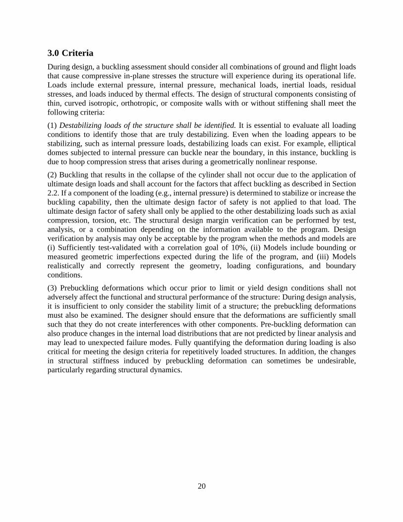
20
3.0 Criteria
During design, a buckling assessment should consider all combinations of ground and flight loads
that cause compressive in-plane stresses the structure will experience during its operational life.
Loads include external pressure, internal pressure, mechanical loads, inertial loads, residual
stresses, and loads induced by thermal effects. The design of structural components consisting of
thin, curved isotropic, orthotropic, or composite walls with or without stiffening shall meet the
following criteria:
(1) Destabilizing loads of the structure shall be identified. It is essential to evaluate all loading
conditions to identify those that are truly destabilizing. Even when the loading appears to be
stabilizing, such as internal pressure loads, destabilizing loads can exist. For example, elliptical
domes subjected to internal pressure can buckle near the boundary, in this instance, buckling is
due to hoop compression stress that arises during a geometrically nonlinear response.
(2) Buckling that results in the collapse of the cylinder shall not occur due to the application of
ultimate design loads and shall account for the factors that affect buckling as described in Section
2.2. If a component of the loading (e.g., internal pressure) is determined to stabilize or increase the
buckling capability, then the ultimate design factor of safety is not applied to that load. The
ultimate design factor of safety shall only be applied to the other destabilizing loads such as axial
compression, torsion, etc. The structural design margin verification can be performed by test,
analysis, or a combination depending on the information available to the program. Design
verification by analysis may only be acceptable by the program when the methods and models are
(i) Sufficiently test-validated with a correlation goal of 10%, (ii) Models include bounding or
measured geometric imperfections expected during the life of the program, and (iii) Models
realistically and correctly represent the geometry, loading configurations, and boundary
conditions.
(3) Prebuckling deformations which occur prior to limit or yield design conditions shall not
adversely affect the functional and structural performance of the structure: During design analysis,
it is insufficient to only consider the stability limit of a structure; the prebuckling deformations
must also be examined. The designer should ensure that the deformations are sufficiently small
such that they do not create interferences with other components. Pre-buckling deformation can
also produce changes in the internal load distributions that are not predicted by linear analysis and
may lead to unexpected failure modes. Fully quantifying the deformation during loading is also
critical for meeting the design criteria for repetitively loaded structures. In addition, the changes
in structural stiffness induced by prebuckling deformation can sometimes be undesirable,
particularly regarding structural dynamics.

21
4.0 Recommended Practices
The following three different approaches for the estimation of buckling loads for circular
cylindrical shells subjected to various loading conditions are described in this section:
(1) Empirical Approach (Section 4.1): The Empirical Approach relies on cylinder buckling test
data to experimentally derive knockdown factors (KDFs), and then applies the KDF to the
predicted buckling eigenvalue for a specific geometry and loading condition. This approach is
suitable for use (i) during the preliminary design process when insufficient information is available
to derive a high fidelity analysis-based buckling load prediction; or (ii) when the primary failure
mode is not driven by buckling and conservative buckling load calculations are adequate for
producing design margins. If buckling is the driving mode, then weight savings can be achieved if
a Semi-Empirical or Analysis-Based design approach is used as they could result in a safe but less
conservative knockdown factor.
(2) Semi-Empirical Approach (Section 4.2): The Semi-Empirical Approach was developed to
provide improved buckling load predictions for the design of orthotropic, stiffened, and core-filled
cylinders and overcome the impracticality of testing all possible combinations of influential design
parameters that would be needed to support a purely empirical design approach. The approach
combines Koiter’s asymptotic theory and the wide-column buckling approach to produce
conservative estimates of the buckling load, and accounts for the effects of initial imperfections.
The Semi-Empirical Approach is suitable for any cylinder configuration, but is most beneficial for
configurations that exhibit reduced imperfection sensitivity as compared to a simply-supported,
isotropic cylinder. Examples of these cases include stiffened cylinders, composite cylinders, short
cylinders, cylinders with elastic core, pressurized cylinders, and cylinders with clamped boundary
conditions. It is recommended that the Empirical Approach be employed in parallel with this
approach as a confidence check.
(3) Analysis-Based Approach (Section 4.3): The Analysis-Based Approach is to use high-fidelity
nonlinear analysis simulations to determine the buckling design loads. However, the methods and
models utilized in this approach often require significant development and validation testing.
These models must incorporate measured or worst-expected imperfections and accurately or
conservatively represent the structural and loading configurations. This approach is suitable when
buckling drives the design, the weight needs to be optimized, and all necessary data and all
validated models are available to perform this high-fidelity Analysis-Based Approach.
Section 4.0 from the previous version of the NASA SP-8007 (1968) [1] has been expanded to
include the Semi-Empirical Approach and the Analysis-Based Approach, both of these approaches
have the potential for cost and weight savings for a given application. In addition, improvements
and additional configurations were added to the Empirical Approach (Section 4.1), such as Special
Design Features (e.g., cutouts, joints).
Generally, a summary of the approaches is presented when practical, or the procedures are merely
outlined when they are complicated and are suitably available in a reference. In all cases,
recommended procedures are not a replacement for sound engineering judgement and experience
and should be modified as needed if supported by technical rational and/or by physical testing.

22
4.1 Empirical Design Approach
This section provides closed form or graphical solutions for buckling criteria of cylinders under
various loading and geometric configurations. A correlation factor or knockdown factor 𝛾 is used
to correlate the linear buckling solution with the experimental results.
Throughout this section, many of the empirical equations will depend on the curvature parameter
𝑍. Depending on the value of 𝛾𝑍 and load case under consideration, cylinders are classified as
short, moderately long, or long cylinders. The user should recognize that these definitions apply
only to that specific load case and that different analyses may have different definitions. In
addition, these definitions are not rigid and are only intended to aid in the solution process.
Engineering judgement must always be used to determine the applicability of a solution to a
specific problem.
Isotropic Unstiffened Cylinders
Unstiffened isotropic circular cylinders subjected to various loading conditions are considered in
this section. In the theoretical analysis of cylinders, it is usually necessary to take account of
prebuckling deformations and stresses [34] and end conditions [42, 135, 136] as they can have a
significant influence on the buckling response. However, the difference between rigorous solutions
for various end support conditions can be obscured by the effects of initial geometric
imperfections. Furthermore, the actual support conditions that exist in aerospace hardware are
typically not well defined in the preliminary stages of design and the characteristics of the actual
geometric imperfection may not be known. It is therefore customary to use simplified theoretical
calculations that are adjusted by using a knockdown factor to account for the differences between
theory and test.
Axial Compression
Buckling and collapse are identical states for isotropic circular cylinders subjected to axial
compression. An equation for the buckling line load of a simply supported cylinder under axial
compression, 𝑁𝑥, has been derived based on Donnell’s shell theory [93]
𝑁𝑥 = 𝑘𝑥
𝜋2𝐷
𝐿2 1
where 𝑘𝑥 is the buckling coefficient, 𝐷 is the wall flexural stiffness per unit width:
𝑘𝑥 = 𝑚2(1 + 𝛽2)2 +12
𝜋4
(𝛾𝑍)2
𝑚2(1 + 𝛽2)2 2
𝐷 =𝐸𝑡3
12(1 − 𝜈2) 3
𝑍 =𝐿2
𝑟𝑡√1 − 𝜈2
4
𝛽 =𝑛𝐿
𝑚𝜋𝑟 5
The cylinder length, radius, and wall thickness are respectively denoted by 𝐿, 𝑟, and 𝑡; the Young’s
Modulus and Poisson’s Ratio are respectively denoted by 𝐸 and 𝑣; and the number of axial half-
waves and circumferential full waves of the buckling mode shape are respectively denoted by 𝑚
and 𝑛. 𝑍 is the curvature parameter, and 𝛽 is the buckle aspect ratio.
The buckling knockdown factor 𝛾 has been added to the second term in Eq. 2 (associated with the
cylinder curvature) to account for the differences between theoretical buckling loads and loads

23
obtained from tests. The form of the buckling coefficient first appeared in the SP-8007 1965 and
is likely derived from results provided in [137]. Minimization of Eq. 2 with respect to 𝑚 and
results in the variation of the buckling coefficient with 𝛾𝑍, Figure 4-1.
Figure 4-1: Buckling coefficients for simply supported isotropic circular cylinders subjected to
axial compression.
For moderately long cylinders, where 𝛾𝑍 > 2.85, or >𝜋2√3
6, the buckling coefficient can be
approximated by Eq. 6.
𝑘𝑥 =4√3
𝜋2𝛾𝑍
6
Substitution of Eq. 6 into Eq. 1 results in a reduced form of 𝑁𝑥 from which the critical axial stress
can be determined by dividing 𝑁𝑥 by the shell thickness, 𝑡.
𝜎𝑥 =𝛾 𝐸
√3(1 − 𝜈2) 𝑡
𝑟 7
= 0.605 𝛾 𝐸𝑡
𝑟 (for 𝜈 = 0.3) 8
By assuming a value of 𝛾 equal to 1.0, one obtains the theoretical buckling equation given in [93].
However, on the basis of various experimental data, it is recommended that a knockdown factor 𝛾
less than 1.0 be used to account for difference between the predicted buckling load and the actual
buckling load determined from tests. An empirical factor (i.e., correlation factor, knockdown
factor) recommended from [101] is given by
𝛾 = 1 − 0.901(1 − 𝑒−𝜙) 9

24
where
𝜙 =1
16√
𝑟
𝑡 (for
𝑟
𝑡< 1500) 10
Equation 9 is shown graphically in Figure 4-2 and provides a good lower bound for most test data
that was compiled from the 1930s to the 1960s. The multiplier 0.606 in Figure 4-2 best provides
the curve fit from the data and it comes from Reference [103].
Figure 4-2: Lower bound design recommendation for thin-walled isotropic
cylinders subjected to axial compression.
(Top: actual test data with a 0.606 multiplier on on linear scale; Bottom:
Eq.9 on log-linear scale) per [103]

25
It should be noted that Donnell’s buckling load predictions given by Eq. 1 cannot predict column
buckling or the interaction between shell buckling (i.e., general instability) and column buckling
[72]. In particular, the buckling load given by Eq. 1 becomes unconservative for large 𝐿/𝑟 ratios.
If designing thin-walled cylindrical struts or long tanks without intermediate ring frames, the
column buckling failure mode and shell buckling-column buckling interaction should be
evaluated. Sanders’ nonlinear shell theory [95] is better suited for the prediction of the theoretical
buckling loads for long cylinders. Additionally, the knockdown factor, 𝛾, given by Eq. 9 should
be used with caution for cylinders with ratios of 𝐿/𝑟 > 5 since correlation has not been verified
by experiment in this range. Finally, it is generally accepted that the knockdown factor equation
in Eq. 9 is likely to bound what is expected in the design of aerospace-quality cylinders which
have well-controlled manufacturing processes. Testing has shown that buckling loads are higher
than the lower bound design curve given by Eq. 9. These higher loads are most likely a result of
greater quality control associated with the fabrication and testing of these structures, which
minimizes the effects of initial geometric imperfections and loading nonuniformities. Alternate
methods for defining less conservative, realistic knockdown factors are presented in Section
4.2and Section 4.3.
When geometry and material properties are such that the computed buckling stresses are in the
plastic range, the value of Young’s Modulus, 𝐸, in Eq. 3 and 8 should be replaced by the value 𝜂𝐸
where
𝜂 =√𝐸𝑠𝑒𝑐𝐸𝑡𝑎𝑛
𝐸
11
Equation 11 is an approximation of the plasticity factors given in [137, 138] and applies to
moderately long cylinders. For extremely short cylinders (𝑍 → 0), the appropriate plasticity factor
as presented in [139], is given by:
𝜂 =𝐸𝑡𝑎𝑛
𝐸 12
For cylinders with a length between those for which Eq. 11 and Eq. 12 apply, it is presumed that
a linear interpolation with 𝑍 between the factors given by Eq. 11 and Eq. 12 would provide
satisfactory results.
Bending
Buckling and collapse are identical states for isotropic cylinders subjected to bending. In [140],
Seide showed that the predicted maximum buckling axial stress due to pure bending for a finite
length simply supported cylinder was approximately equal to that for uniform axial compression.
Thus, the procedures given for compression-loaded isotropic cylinders may be used to obtain the
critical maximum stress for isotropic cylinders in bending except that a correlation factor specific
for the bending load condition should be used. The critical bending moment, 𝑀𝑐𝑟, can be
approximated by
𝑀𝑐𝑟 = 𝜋𝑟2𝑁𝑥 = 𝑘𝑥
𝜋3𝐷𝑟2
𝐿2 13

26
where 𝑘𝑥 is represented by Eq. 2, identical to the case for axial compression.
The knockdown factor for cylinders in bending is taken from [103] as
𝛾 = 1 − 0.731(1 − 𝑒−𝜙) 14
where
𝜙 =1
16√
𝑟
𝑡 (for
𝑟
𝑡< 1500) 15
Equation 15 should be used with caution for 𝑟
𝑡> 1500 because experimental data are not available
in this range. Although the theoretical critical stress is assumed to be the same for axial
compression and bending, the correlation factor for bending is greater than that for compression
due to the reduced imperfection sensitivity exhibited by cylinders in bending.
Designs should be verified to protect against cross section collapse. For sufficiently long shells, it
has been found [141] that a circular cylindrical tube cross section ovalizes progressively when an
initially straight tube is subjected to uniform bending and this, in turn, reduces the flexural stiffness
and results in premature cross-sectional buckling of the tube. This cross-sectional buckling is
characterized by the formation of a crease followed by complete flattening of cross-section and
significant loss of structural stiffness [142]. For sufficiently long shells, the critical bending
moment for cross section collapse is given by
𝑀𝑐𝑟 = 0.987 𝐸 𝑟 𝑡2
√1 − 𝜈2 16
It was demonstrated in [143] that bifurcation buckling occurs before the cross-sectional collapse
limit point regardless the level of internal pressure, indicating that cross-sectional collapse may
not always be the only design driver. Stephens et al. studied cylinders loaded by pure bending and
cylinders under combined loads of bending and internal or external pressure [144]. Their work
found that critical moment increased relative to increasing internal pressure of the cylinder.
Conversely, critical moment was found to decrease relative to increasing external pressure, below
the critical moment associated with cross-sectional collapse in unpressurized cylinders.
External Pressure
Two types of external pressure are considered: hydrostatic and lateral. Except for short cylinders,
the critical buckling pressures for hydrostatic and lateral are essentially the same.
The term lateral pressure corresponds to an external pressure, 𝑝, which acts only on the curved
walls of the cylinders and not on the ends (e.g., bulkheads). Circumferential stress, 𝜎𝑦, and
circumferential line load, 𝑁𝑦, are related through thickness and to the applied external pressure, 𝑝,
and are given by
𝜎𝑦 =𝑝𝑟
𝑡=
𝑁𝑦
𝑡 17

27
The term hydrostatic pressure corresponds to an external pressure, 𝑝, which acts on both the
curved walls and the ends of the cylinder. In this case, the circumferential loads are identical to
Eq. 17 and axial loads in the shell wall are given by
𝜎𝑥 =𝑝𝑟
2𝑡=
𝑁𝑥
𝑡 18
Except for sufficiently short cylinders (𝛾𝑍 < 100), the critical pressures for the two different
types of loads are not significantly different. An approximate equation for the buckling of cylinders
subjected to lateral pressure is given in [93] as
𝑁𝑦 = 𝑘𝑦
𝜋2𝐷
𝐿2 19
where the buckling coefficient is
𝑘𝑦 =𝑝𝑟𝐿2
𝜋2𝐷=
1
𝛽2[(1 + 𝛽2)2 +
12
𝜋4
𝛾2𝑍2
(1 + 𝛽2)2]. 20
The equation for buckling of cylinders subjected to hydrostatic pressure is obtained by replacing
the 𝑘𝑦 in Eq. 19 by 𝑘𝑝 and the factor 𝛽2 before the bracketed expression in Eq. 20 is replaced by
(𝛽2 +1
2). That is
𝑁𝑦 = 𝑘𝑝
𝜋2𝐷
𝐿2 21
where the buckling coefficient is
𝑘𝑝 =𝑝𝑟𝐿2
𝜋2𝐷=
1
(𝛽2 +12)[(1 + 𝛽2)2 +
12
𝜋4
𝛾2𝑍2
(1 + 𝛽2)2] 22
The term 𝛾2 has been added to Eq. 20 and Eq. 22 as a correction for the difference between theory
and test.
The minimum values of 𝑘𝑦 for lateral pressure and 𝑘𝑝 for hydrostatic pressure are obtained by
allowing the buckle aspect ratio, 𝛽 to vary continuously and are shown in Figure 4-3. For
𝛾𝑍 > 100, 𝑘𝑦 and 𝑘𝑝 are given by the following equation [93]:
𝑘𝑦 = 𝑘𝑝 = 1.04 √𝛾𝑍 23
The critical pressure then corresponds to
𝑝𝑐𝑟 =0.855
(1 − 𝜈2)34
𝐸√𝛾
(𝑟𝑡)
52(𝐿𝑟)
24
For 𝜈 = 0.316, Eq. 24 further simplifies to
𝑝𝑐𝑟 = 0.926 𝐸√𝛾
(𝑟𝑡)
52(𝐿𝑟)
25
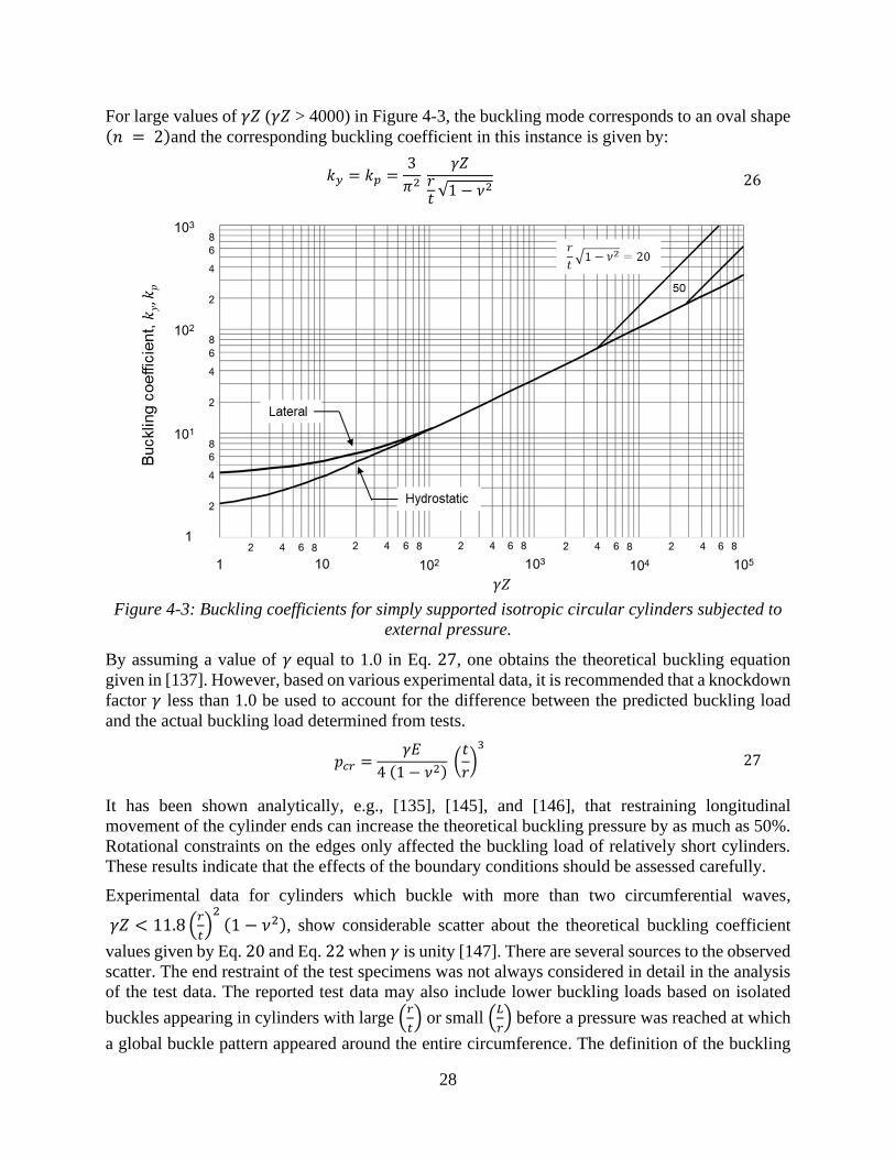
28
For large values of 𝛾𝑍 (𝛾𝑍 > 4000) in Figure 4-3, the buckling mode corresponds to an oval shape (𝑛 = 2)and the corresponding buckling coefficient in this instance is given by:
𝑘𝑦 = 𝑘𝑝 =3
𝜋2
𝛾𝑍𝑟𝑡√1 − 𝜈2
26
Figure 4-3: Buckling coefficients for simply supported isotropic circular cylinders subjected to
external pressure.
By assuming a value of 𝛾 equal to 1.0 in Eq. 27, one obtains the theoretical buckling equation
given in [137]. However, based on various experimental data, it is recommended that a knockdown
factor 𝛾 less than 1.0 be used to account for the difference between the predicted buckling load
and the actual buckling load determined from tests.
𝑝𝑐𝑟 =𝛾𝐸
4 (1 − 𝜈2) (
𝑡
𝑟)3
27
It has been shown analytically, e.g., [135], [145], and [146], that restraining longitudinal
movement of the cylinder ends can increase the theoretical buckling pressure by as much as 50%.
Rotational constraints on the edges only affected the buckling load of relatively short cylinders.
These results indicate that the effects of the boundary conditions should be assessed carefully.
Experimental data for cylinders which buckle with more than two circumferential waves,
𝛾𝑍 < 11.8 (𝑟
𝑡)2(1 − 𝜈2), show considerable scatter about the theoretical buckling coefficient
values given by Eq. 20 and Eq. 22 when 𝛾 is unity [147]. There are several sources to the observed
scatter. The end restraint of the test specimens was not always considered in detail in the analysis
of the test data. The reported test data may also include lower buckling loads based on isolated
buckles appearing in cylinders with large (𝑟
𝑡) or small (
𝐿
𝑟) before a pressure was reached at which
a global buckle pattern appeared around the entire circumference. The definition of the buckling

29
for these cases is a matter of individual judgement and may vary in different tests by different
investigators. For cylinders subjected to hydrostatic pressure, the induced axial compression load
and imperfection sensitivity characteristics may also have a significant influence on the buckling
response. Later work [20] indicated significantly better correlation between test and analysis due
to improved testing methods and specimen fabrication. However, because some of the test loads
from previous testing are as much as 25% below the theoretical results, a conservative correlation
factor of
√𝛾 = 0.75, 𝛾 = 0.5625 28
is recommended for use with Eq.23-25.
For long cylinders that buckle into an oval shape, there is less of a discrepancy between theory and
experiment [148] and a correlation factor of
𝛾 = 0.90 29
is recommended for use with Eq. 26 and 27.
For relatively short cylinders (𝛾𝑍 < 5) under lateral pressure, the plasticity factor for long, simply
supported plates in axial compression may be used [139] and is shown by
𝜂 =𝐸𝑠𝑒𝑐
𝐸(1
2+
1
2√
1
4+
3
4
𝐸𝑡𝑎𝑛
𝐸𝑠𝑒𝑐) 30
For 100 < 𝛾𝑍 < 11.8 (𝑟
𝑡)2(1 − 𝜈2), the approximate plasticity factor is obtained from [148] as
𝜂 =𝐸𝑠𝑒𝑐
𝐸√(
𝐸𝑡𝑎𝑛
𝐸𝑠𝑒𝑐)
12(1
4+
3
4
𝐸𝑡𝑎𝑛
𝐸𝑠𝑒𝑐)
31
For 𝛾𝑍 > 11.8 (𝑟
𝑡)2(1 − 𝜈2) the approximate plasticity factor is obtained from [137] as
𝜂 =𝐸𝑠𝑒𝑐
𝐸(1
4+
3
4
𝐸𝑡𝑎𝑛
𝐸𝑠𝑒𝑐) 32
No plasticity factor is available for the range 5 < 𝛾𝑍 < 100; satisfactory results may, however, be
achieved by linear interpolation with the parameter 𝑍 between the values of 𝜂 given by
Eq. 30 and 31.
Plasticity factors for the biaxial stress state of hydrostatic pressure are unavailable. For lack of
better information, the plasticity factors given by Eq. 30-32 may be used.
Torsion
Buckling generally corresponds with collapse loads for unstiffened cylinders in torsion. The
theoretical buckling coefficient for cylinders in torsion, 𝑘𝑥𝑦, can be obtained from Figure 4-4,
which is taken from [93]. For very short cylinders, the value of the critical shear-stress coefficient
approaches the value of a flat plate in shear equal to 5.34 when the edges are simply supported.
The straight-line portion of the curve is given by
𝑘𝑥𝑦 =𝑁𝑥𝑦𝐿2
𝜋2𝐷= 0.85 (𝛾𝑍)
34 33

30
Figure 4-4: Buckling coefficients for simply supported isotropic circular cylinders subjected to
torsion.
𝑁𝑥𝑦 is the critical torsion load per unit length around the circumference of the cylinder. The
correlation factor 𝛾 has been included to account for the differences between theory and test.
Torsional critical stress, 𝜏𝑐𝑟, can be expressed as
𝜏𝑐𝑟 = 𝑁𝑥𝑦
𝑡 =
0.747 𝛾34 𝐸
(𝑟𝑡)
54(𝐿𝑟)
12
34
To approximate the lower bound to most buckling data provided in [93], the value
𝛾34 = 0.67
35
is recommended for moderately long cylinders, 50 < 𝛾𝑍 < 78 (𝑟
𝑡)2(1 − 𝜈2).
For very long cylinders, 𝛾𝑍 > 78 (𝑟
𝑡)2(1 − 𝜈2), the cylinder buckles into a mode shape with two
circumferential waves (𝑛 = 2). The critical buckling stress given in [149] is
𝜏𝑐𝑟 =𝛾𝐸
3√2 (1 − 𝜈2)34
(𝑡
𝑟)
32
36
and corresponds to a buckling coefficient of
𝑘𝑥𝑦 = 2√2 𝑍𝜋2 (𝑟
𝑡)
12(1 − 𝜈2)
14
37
z
Bucklin
g c
oeffi
cie
nt,
kxy
1
10
100
1000
1 10 100 1000 10000 100000

31
For very long cylinders, the following knockdown factor is recommended.
𝛾 = 0.80 38
Critical buckling stress from Eq. 36 can be related to critical buckling torque load, 𝑇𝑐𝑟, through
the following equation
𝑇𝑐𝑟 = 2 𝜋 𝑟 𝜏𝑐𝑟 39
Plasticity may be taken into account by applying the plasticity factor, 𝜂, from [148] into
Eq. 34 and 36, where
𝜂 =𝐸𝑠𝑒𝑐
𝐸 40
The quantity 𝐸𝑠𝑒𝑐 is obtained from a uniaxial stress-strain curve at a normal stress equal to twice
the critical shear stress. Equation 40 applies to cylinders of all lengths.
Combined Loads
Typical load combinations encountered in practice are treated here. Generally, the recommended
practice to account for combinations of two or more loading conditions that may cause buckling
is to assume that the sum of the various critical load ratios is equal to unity. However, it has been
shown theoretically and experimentally, [20] and [137], that this assumption can be conservative
(e.g., combined compression and torsion; combined bending and torsion). Alternate approaches
used to account for the effects of combined loads can yield more accurate and less conservative
buckling load estimates; however, it is advised that these alternate approaches be substantiated by
test or validated buckling load predictions.
4.1.1.5.1 Combined Axial Compression and Bending
The recommended interaction equation for combined axial compression and bending is
𝑅𝑐 + 𝑅𝑏 = 1 41
where the quantities 𝑅𝑐 and 𝑅𝑏 are the compressive and bending load given by
𝑅𝑐 =𝑃
𝑃𝑐𝑟 42
and
𝑅𝑏 =𝑀
𝑀𝑐𝑟 43
𝑃 and 𝑀 are the applied compressive load and applied bending load, respectively. 𝑃𝑐𝑟 is the
allowable axial load, which can be derived from the axial stress in Eq. 7, and 𝑀𝑐𝑟 is the allowable
bending moment which can be found directly from Eq. 13.
4.1.1.5.2 Combined Axial Compression and External Pressure
The recommended interaction equation for combined axial compression and external pressure is
𝑅𝑐 + 𝑅𝑝 = 1 44
32
The quantities 𝑅𝑐 and 𝑅𝑝 are the compressive and hydrostatic- or lateral-pressure load ratios, where
𝑅𝑝 is given by
𝑅𝑝 =𝑝
𝑝𝑐𝑟 45
where 𝑝 is the applied pressure load and 𝑝𝑐𝑟 is the allowable pressure load given by Eq. 24 in
Section 4.1.1.3 for cylinders subjected to external pressure.
4.1.1.5.3 Combined Axial Compression and Torsion
For cylindrical shells subjected to combined axial compression and torsion, the analytical
interaction curve is a function of 𝑍. The experimental test data suggest the use of a straight-line
interaction equation
𝑅𝑐 + 𝑅𝑡 = 1 46
The quantities 𝑅𝑐 and 𝑅𝑡 are the compressive and torsion load ratios, respectively, where 𝑅𝑡 is
given by
𝑅𝑡 =𝑇
𝑇𝑐𝑟 47
and 𝑇 is the applied torque load and 𝑇𝑐𝑟 is the allowable torque load given in Section 4.1.1.4for
cylinders subjected to torsion.
4.1.1.5.4 Combined Axial Compression and Internal Pressure
Buckling and collapse typically match for cylinders subjected to combined internal pressure and
axial compression. The internal pressure increases the buckling load of the cylinder in the
following ways:
1. The total axial compressive load must be greater than the tensile pressurization load in
the shell wall 𝑝𝜋𝑟2 before buckling can occur.
2. The destabilizing effect of initial imperfections is reduced.
3. The circumferential tensile stress induced by the pressurization can inhibit the
formation of the classical diamond-shaped buckling pattern, and, at sufficiently high
pressures, the cylinder buckles into the classical axisymmetric mode at approximately
the classical buckling stress.
Lower bound curves giving the increase in buckling load as a function of internal pressure, based
on the results for Mylar cylinders, are given in [150] for various radius-to-thickness ratios. Because
these curves are unsubstantiated at present for other materials, the more conservative values given
in [109] are recommended for design use. It is therefore recommended that the total load for
buckling, unless substantiated by test, be obtained by the addition of the pressurization load 𝑝𝜋𝑟2,
the buckling load for the unpressurized cylinder (Eq. 1), and an increase in the buckling load
caused by the pressurization; that is
𝑃𝑝𝑟𝑒𝑠𝑠 = 2𝜋𝐸𝑡2 (𝛾
√3(1 − 𝜈2)+ 𝛥𝛾) + 𝑝𝜋𝑟2
48

33
where 𝑃𝑝𝑟𝑒𝑠𝑠 is the load at collapse of an internally pressurized cylinder, Δ𝛾 is obtained from Figure
4-5. For 𝜈 = 0.3, Eq. 48 simplifies to
𝑃𝑝𝑟𝑒𝑠𝑠 = 2𝜋𝐸𝑡2 (0.605𝛾 + 𝛥𝛾) + 𝑝𝜋𝑟2 49
The Δ𝛾 curve provided in Figure 4-5 should only be used with the equations presented here.
Application of data from Figure 4-5 to other untested cylinder configurations or use with other less
conservative knockdown factors could result in unconservative designs.
4.1.1.5.5 Combined Bending and Internal Pressure
For cylinders subjected to combined internal pressure and bending, collapse loads are considerably
higher than buckling loads [151, 152, 153], with the increase being substantially more than the
tension stress induced by the pressurization. For example, very thin-walled cylinders (𝑟
𝑡= 6000)
have been shown to experience pressure stiffening characteristics where the collapse load is as
much as twice the initial buckling load [154]. The theoretical collapse load is, however,
unattainable unless large undesirable deformations are present. It is therefore recommended that
the collapse moment for pressurized cylinders be obtained by adding the moment-carrying
capability of a pressurized membrane cylinder (taken for design purposes as 80% of the theoretical
value), the collapse moment for the unpressurized cylinder (Eq. 13), and an increase in the critical
moment caused by pressurization. Then
𝑀𝑝𝑟𝑒𝑠𝑠 = 𝜋𝑟𝐸𝑡2 (𝛾
√3(1 − 𝜈2)+ 𝛥𝛾) + 0.8 𝑝𝜋𝑟3
50
where 𝑀𝑝𝑟𝑒𝑠𝑠 is the bending moment of collapse of an internally pressurized cylinder, Δ𝛾 is
obtained from Figure 4-5. For 𝜈 = 0.3, Eq. 50 simplifies to
𝑀𝑝𝑟𝑒𝑠𝑠 = 𝜋𝑟𝐸𝑡2 (0.605𝛾 + 𝛥𝛾) + 0.8 𝑝𝜋𝑟3 51
Figure 4-5: Increase in axial buckling knockdown factor (correlation coefficient) for pressurized
cylinders.
D
0.01
0.1
1
10
0.01 0.1 1 10
(p/E) (R/t)2(p/E) (r/t)2

34
4.1.1.5.6 Combined Axial Compression, Bending, and Internal Pressure
For internally pressurized cylinders subjected to combined axial compression and bending, Eq. 41
is recommended for use in combination with Eq. 48 and Eq. 50.
Orthotropic Cylinders
The term orthotropic cylinders covers a wide variety of cylinder configurations. In the strictest
sense, it denotes cylinders made of a single orthotropic material or of multiple orthotropic layers.
It also denotes stiffened cylinders for which the stiffener geometry and spacing is such that the
cylinder can be approximated by a fictitious layer whose orthotropic bending and extensional
properties include those of the individual stiffening element averaged or smeared out over
representative widths or areas. Generally, the directions of the axes of orthotropy are taken to
coincide with the longitudinal and circumferential directions of the cylinder.
The buckling behavior of various types of orthotropic cylinders may be described by a single
theory, the elements of which are equations of equilibrium for the buckled structure, and stress-
strain relations. For cylinders of a single orthotropic layer, it is generally permissible to neglect
coupling between membrane stresses and bending strains, and between moment resultants and
extensional strains. The theory is then similar to that for isotropic cylinders. For stiffened cylinders
or for cylinders having multiple orthotropic layers, however, the neglect of coupling terms can
lead to significant errors.
For example, cylinders that have stiffeners on the inner surface or on the outer surface will exhibit
bending-extension coupling due to the eccentricity of the stiffeners relative to the mid-surface of
the cylinder wall. In addition, the character of the coupling will be different depending on the
orientation of the stiffeners and if the stiffeners are on the inside or the outside, and can have a
significant influence on the buckling response of the cylinder [155, 156, 157, 158, 159]. In
particular, the eccentricity effect is very pronounced for axially stiffened cylinders in compression.
Similarly, laminated composite cylinders can exhibit various types of elastic coupling even if the
laminate is balanced and symmetric [160].
In stiffened cylinders, other failure modes should also be investigated including local skin buckling
between stiffeners, as well as stiffener buckling and stiffener crippling. In addition, the adequacy
of the smeared stiffener theory should be investigated if the spacing of the stiffeners becomes
sufficiently large, or if large-magnitude geometrically nonlinear prebuckling deformations are
anticipated [25].
Axial Compression
An equation for the buckling of orthotropic cylinders in compression [161] is given by:
𝑁𝑥 = (𝐿
𝑚 𝜋)2|
𝐴11 𝐴12 𝐴13
𝐴21 𝐴22 𝐴23
𝐴31 𝐴32 𝐴33
|
|𝐴11 𝐴12
𝐴21 𝐴22|
𝑓𝑜𝑟 𝑛 ≥ 4 52
or
𝑁𝑥 (𝑚 𝜋
𝐿)2
= 𝐴33 + 𝐴23 (𝐴13𝐴12 − 𝐴11𝐴23
𝐴11𝐴22 − 𝐴122 ) + 𝐴13 (
𝐴12𝐴23 − 𝐴13𝐴22
𝐴11𝐴22 − 𝐴122 ) 53

35
where
𝐴11 = ��𝑥 (𝑚 𝜋
𝐿)2
+ ��𝑥𝑦 (𝑛
𝑟)2
54
𝐴22 = ��𝑦 (𝑛
𝑟)2
+ ��𝑥𝑦 (𝑚 𝜋
𝐿)2
55
𝐴33 = ��𝑥 (𝑚 𝜋
𝐿)4
+ ��𝑥𝑦 (𝑚 𝜋
𝐿)2
(𝑛
𝑟)2
+ ��𝑦 (𝑛
𝑟)4
+��𝑦
𝑟2+
2 𝐶��
𝑟(𝑛
𝑟)
2
+2 ��𝑥𝑦
𝑟(𝑚 𝜋
𝐿)2
56
𝐴12 = 𝐴21 = (��𝑥𝑦 + ��𝑥𝑦) 𝑚 𝜋
𝐿 𝑛
𝑟 57
𝐴23 = 𝐴32 = (𝐶��𝑦 + 2𝐾𝑥𝑦) (𝑚 𝜋
𝐿)2 𝑛
𝑟+
��𝑦
𝑟
𝑛
𝑟+ 𝐶�� (
𝑛
𝑟)3
58
𝐴31 = 𝐴13 =��𝑥𝑦
𝑟 𝑚 𝜋
𝐿+ 𝐶�� (
𝑚 𝜋
𝐿)3
+ (𝐶��𝑦 + 2𝐾𝑥𝑦)𝑚 𝜋
𝐿(𝑛
𝑟)2
59
Values of the stiffnesses ��𝑥, ��𝑥𝑦, ��𝑦, ��𝑥𝑦, ��𝑥, ��𝑥𝑦, ��𝑦, ��𝑥, ��𝑥𝑦, ��𝑦, and ��𝑥𝑦, for various types of
construction are given in Section 4.1.2.6. Prebuckling deformations are not considered in the
derivation of the equation. The cylinder edges are assumed to be simply supported, that is the radial
displacements are restrained (pinned) but rotation about the tangent is unrestrained (free). These
conditions are assumed to be representative of rings that are rigid in their own plane but offer no
resistance to rotation or bending out of their plane. For ring-stiffened corrugated cylinders, a
similar but not identical theory is given in [117, 162]. For given cylinder and stiffener dimensions,
the values of m and n (the number of axial half waves and circumferential full-waves, respectively)
to be used are those that minimize the buckling load 𝑁𝑥. The above equations become less accurate
for moderately long cylinders when 𝑛 ≤ 4, as compared to Love or Sanders. Errors can range from
10% − 40%.
The large number of parameters in Eq. 52 does not permit a complete treatment of results to be
shown. However, some generalizations can be made, and references are provided. For
combinations of parameters representative of stiffened shells, calculations indicate that external
stiffening, whether rings or axial stiffeners (stringers) or both, can be more effective than internally
stiffened cylinders for axial compression. Generally, calculations neglecting stiffener eccentricity
yield unconservative values of the buckling load of internally stiffened cylinders and conservative
values of the buckling load for externally stiffened cylinders [163]. In addition, boundary
conditions and loading can have a significant effect on these trends [57]. An extensive
investigation of the variation of the buckling load with various stiffener parameters is reported in
[128, 155]. Experimental data [117, 118, 119, 120, 121] [57, 164, 165, 166, 167, 168] for cylinders
with closely spaced stiffeners and comparisons to linear buckling results were investigated for a
range of geometric parameters. Comparisons improve with increasing area parameter greater than
0.3, which is defined as the ratio of cross-sectional area of rings to thickness of the shell times the
spacing between rings.
Experimental buckling loads have been shown to be as low as 65% of the predicted classical
buckling load. Thus, it is recommended that the buckling loads for a uniform cylinder with closely
spaced, moderately large stiffeners calculated from Eq. 52 be multiplied by a factor of 0.65. While

36
[1] suggested a knockdown factor equal to 0.75, a knockdown factor of 0.65 is recommended based
on the results presented in [5] and [6]. Less conservative analysis-based factors can be derived
based on an approach outlined in Section 4.3.
Knockdown factors covering the transition from unstiffened cylinders to cylinders with closely
space stiffeners have not been fully investigated and may require investigation via detailed analysis
and or experimental testing. While theory and experiment [123] indicate that restraint against edge
rotation and longitudinal movement can significantly increase the buckling load, not enough is
known about the edge restraint of actual cylinders to warrant taking advantage of these effects
unless substantiated by detailed analysis or tests.
For layered or unstiffened orthotropic cylinders, the available test data have increased substantially
since [1] was written and the results indicate higher buckling loads as compared to older isotropic
data and the lower-bound design curve of Eq. 9 and Figure 4-2. Additional test data is available
for filament-wound cylinders [169, 170, 171, 172], laminated composite cylinders [10, 11] [173,
174, 175, 176, 177, 178], and stiffened composite cylinders [179]. However, due to the tremendous
number of possible design variables and structural configurations, no new empirical guidelines
have been developed based on this data. Thus, the KDF 𝛾 is taken to be of the same form as for
the isotropic cylinders (Eq. 9) with the thickness 𝑡 replaced by the geometric mean of the radii of
gyration for the axial and circumferential directions. Thus
𝛾 = 1 − 0.901(1 − 𝑒−𝜙) 60
where
𝜙 =1
29.8
[
𝑟
√��𝑥��𝑦
��𝑥��𝑦
4
] 12
61
As discussed above, more recent testing has produced buckling loads that are often significantly
higher than the lower bound design curve given by Eq. 9. It is not uncommon to obtain
experimental buckling loads for uniform cylinders of 70−90% of the theoretical predictions. These
higher loads are most likely a result of greater quality control associated with the fabrication and
testing of these structures, which minimizes the effects of initial geometric imperfections and
loading nonuniformities. However, given the extreme imperfection sensitivity of compression-
loaded thin-walled cylinders, the design factors provided herein should be used unless alternate
values can be justified. Alternate methods, including Semi-Empirical and high-fidelity analysis-
based methods, for determining less conservative knockdown factors are presented in Sections 4.2
and 4.3.
Bending
Theoretical and experimental results for stiffened cylinders in bending can be found in [124, 125,
126] [162] [180, 181, 182, 183, 184]. The results indicate that the critical maximum load of a
stiffened cylinder in bending can exceed the critical load in axial compression. However, in the
absence of an extensive investigation, it is recommended that the critical maximum load of a
uniform cylinder with closely spaced stiffeners be taken as equal to the critical load in axial
compression, calculated from Eq. 52 multiplied by a factor 𝛾 = 0.75, which is slightly greater

37
than the factor for compression loaded cylinders due to the reduced imperfection sensitivity. In
addition, as with compression-loaded stiffened cylinders, local skin buckling can also occur prior
to global buckling, as in the case of widely spaced stiffeners, and should be checked.
For layered or unstiffened orthotropic cylinders, it is recommended that the correlation factor
𝛾 = 1 − 0.731(1 − 𝑒−𝜙) 62
be used where
𝜙 =1
29.8
[
𝑟
√��𝑥��𝑦
��𝑥��𝑦
4
] 12
63
External Pressure
The counterpart of Eq. 52 for orthotropic cylinders under lateral pressure the critical pressure is
found by determining the minimum value of
𝑝𝑐𝑟 =𝑟
𝑛2
|
𝐴11 𝐴12 𝐴13
𝐴21 𝐴22 𝐴23
𝐴31 𝐴32 𝐴33
|
|𝐴11 𝐴12
𝐴21 𝐴22|
64
For hydrostatic pressure, the quantity 𝑛2 in Eq. 64 is replaced by
𝑛2 +1
2 (
𝑚 𝜋 𝑟
𝐿)2
65
In the case of lateral pressure, 𝑚 is equal to unity while 𝑛 must be varied to yield a minimum value
of the critical pressure, but not less than 2. In the case of hydrostatic pressure, the value of 𝑚
should be varied along with 𝑛. For long cylinders, Eq. 64 is replaced by
𝑝𝑐𝑟 =
3(��𝑦 −𝐶��
2
𝐸𝑦)
𝑟3
66
If the coupling coefficients can be neglected (i.e., are equal to or close to zero valued), the critical
buckling pressure can be approximated by:
𝑝𝑐𝑟 ≈5.513
𝐿 𝑟32
[��𝑦
3(��𝑥��𝑦 − ��𝑥𝑦
2)
��𝑦]
14
67

38
for the case of
(��𝑦
��𝑥)
32
(��𝑥��𝑦 − ��𝑥𝑦
2
12 ��𝑦��𝑥)
12 𝐿2
𝑟 > 500
68
Equation 64 has been investigated primarily for isotropic cylinders with ring stiffeners [184, 185,
186]. For closely spaced ring stiffening, it is shown that the effectiveness of inside or outside rings
depends on the cylinder and ring geometries. Generally, for cylinders with values of 𝑍 less than
100, outside rings are more effective, while for value of 𝑍 greater than 500, the reverse is true. As
the ring geometry varies, the effectiveness of the outside stiffening tends to increase as the stiffness
of the rings relative to the cylinder increases. Somewhat lower buckling pressures are given by the
more complex but more accurate theory of [187]; however, the differences are not so significant
as to warrant its use.
The experimental results for ring-stiffened cylinders described in [188, 189, 190, 191] are in
reasonably good agreement with the theoretical results of Eq. 64. For cylinders of all types, it is
recommended that the buckling pressure calculated from Eq. 64 be multiplied by a factor of 0.75,
as has been recommended for unstiffened isotropic cylinders of moderate length.
Torsion
Buckling of orthotropic cylinders in torsion has been treated in [94, 192, 193]. If coupling effects
are negligible, the critical torsion load for moderately long cylinders can be estimated based on the
equations provided in [94] as follows:
𝑇𝑐𝑟 ≈ 21.75 ��𝑦
58 (
��𝑥��𝑦 − ��𝑥𝑦2
��𝑦)
38
𝑟
54
𝐿12
69
for the case of
( ��𝑦
��𝑥)
56
(��𝑥��𝑦 − ��𝑥𝑦
2
12 ��𝑦��𝑥)
12
𝐿2
𝑟≳ 500
70
However, [193] indicates that coupling effects can be quite important for cylinders stiffened with
closely spaced rings. For long cylinders, internal rings are generally more effective than outside
rings; for short cylinders, the reverse is true. In the absence of general formulas or graphs for the
range of practical parameters, the equations in [191] should be solved for each specific case
considered.
The limited test data of [194] for relatively short stiffeners are in good agreement with theoretical
predictions but are insufficient to provide an adequate test of the theory for more practical designs.
It is therefore recommended that theoretical critical torsion load 𝑇𝑐𝑟 be multiplied by a factor of
0.67 for moderately long cylinders.
Combined Loads
Based on theory [162, 180, 195] and limited test data [117, 162], interaction equations found in
Section 4.1.1.5 for isotropic cylinders are recommended.

39
However, as discussed in Section 4.1.1.5, it has been shown theoretically and experimentally that
this assumption can be somewhat conservative (e.g., combined compression and torsion and
combined bending and torsion) [20, 137]. Alternate approaches used to account for the effects of
combined loads can yield more accurate and less conservative buckling load estimates; however,
it is advised that these alternate approaches be substantiated by test or validated buckling load
predictions.
Elastic Constants
Equations for the elastic constants for commonly used cylinder wall constructions are provided in
this section, including: Stiffened Multilayered Orthotropic Cylinders, Isotropic Cylinders with
Rings and Stringers, Isotropic Isogrid-Stiffened Cylinders, Ring-Stiffened Corrugated Cylinders.
Equations for determining elastic constants for other stiffener patterns and structural
configurations are presented in Nemeth, including Hexagonal stiffener pattern, Kagome stiffener
pattern, and sandwich plates with nonidentical anisotropic facesheets [196].
4.1.2.6.1 Stiffened Multilayered Orthotropic Cylinders
Commonly used expressions for the elastic constants for multilayered cylinders with isotropic
rings and stringers are [161]:
��𝑥 = ∑ (𝐸𝑥
1 − 𝜈𝑥𝜈𝑦)
𝑘
𝑡𝑘 +𝐸𝑠𝐴𝑠
𝑏𝑠
𝑁
𝑘=1
71
��𝑦 = ∑ (𝐸𝑦
1 − 𝜈𝑥𝜈𝑦)
𝑘
𝑡𝑘 +𝐸𝑟𝐴𝑟
𝑏𝑟
𝑁
𝑘=1
72
��𝑥𝑦 = ∑ (𝜈𝑥𝐸𝑦
1 − 𝜈𝑥𝜈𝑦)
𝑘
𝑡𝑘 = ∑ (𝜈𝑦𝐸𝑥
1 − 𝜈𝑥𝜈𝑦)
𝑘
𝑡𝑘
𝑁
𝑘=1
𝑁
𝑘=1
73
��𝑥𝑦 = ∑(𝐺𝑥𝑦)𝑘𝑡𝑘
𝑁
𝑘=1
74
��𝑥 = ∑ (𝐸𝑥
1 − 𝜈𝑥𝜈𝑦)
𝑘
(1
12𝑡𝑘3 + 𝑡𝑘 ��𝑘
2) +𝐸𝑠𝐼𝑠𝑏𝑠
+ ��𝑠2
𝑁
𝑘=1
𝐸𝑠𝐴𝑠
𝑏𝑠 75
��𝑦 = ∑ (𝐸𝑦
1 − 𝜈𝑥𝜈𝑦)
𝑘
(1
12𝑡𝑘3 + 𝑡𝑘 ��𝑘
2) +𝐸𝑟𝐼𝑟𝑏𝑟
+ ��𝑟2
𝑁
𝑘=1
𝐸𝑟𝐴𝑟
𝑏𝑟 76
��𝑥𝑦 = ∑ (4 𝐺𝑥𝑦 +𝜈𝑥𝐸𝑦
1 − 𝜈𝑥𝜈𝑦+
𝜈𝑦𝐸𝑥
1 − 𝜈𝑥𝜈𝑦)
𝑘
(1
12𝑡𝑘3 + 𝑡𝑘 ��𝑘
2) +𝐺𝑠𝐽𝑠𝑏𝑠
+
𝑁
𝑘=1
𝐺𝑟𝐽𝑟𝑏𝑟
77
𝐶�� = ∑ (𝐸𝑥
1 − 𝜈𝑥𝜈𝑦)
𝑘
𝑡𝑘 ��𝑘 + ��𝑠
𝐸𝑠𝐴𝑠
𝑏𝑠
𝑁
𝑘=1
78
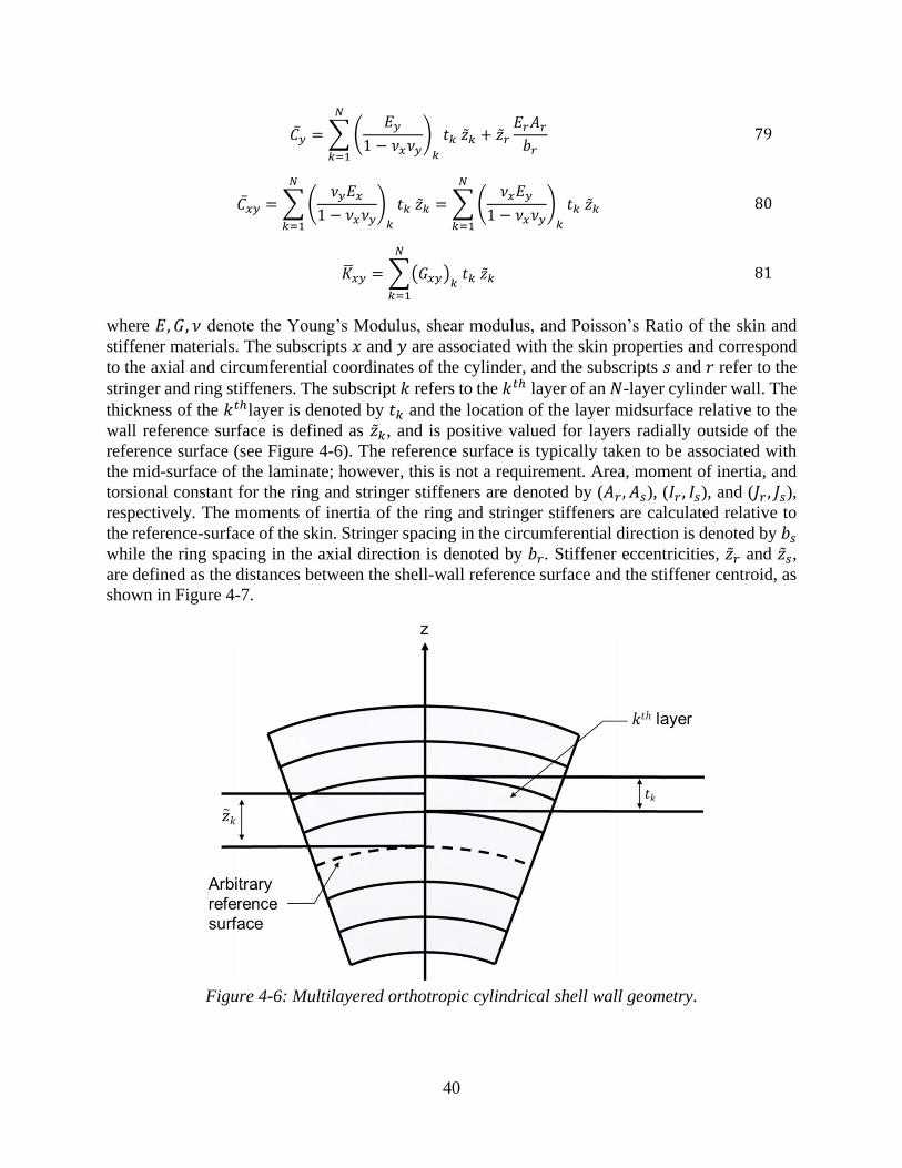
40
𝐶�� = ∑ (𝐸𝑦
1 − 𝜈𝑥𝜈𝑦)
𝑘
𝑡𝑘 ��𝑘 + ��𝑟
𝐸𝑟𝐴𝑟
𝑏𝑟
𝑁
𝑘=1
79
𝐶��𝑦 = ∑ (𝜈𝑦𝐸𝑥
1 − 𝜈𝑥𝜈𝑦)
𝑘
𝑡𝑘 ��𝑘 = ∑ (𝜈𝑥𝐸𝑦
1 − 𝜈𝑥𝜈𝑦)
𝑘
𝑡𝑘 ��𝑘
𝑁
𝑘=1
𝑁
𝑘=1
80
𝐾𝑥𝑦 = ∑(𝐺𝑥𝑦)𝑘 𝑡𝑘 ��𝑘
𝑁
𝑘=1
81
where 𝐸, 𝐺, 𝜈 denote the Young’s Modulus, shear modulus, and Poisson’s Ratio of the skin and
stiffener materials. The subscripts 𝑥 and 𝑦 are associated with the skin properties and correspond
to the axial and circumferential coordinates of the cylinder, and the subscripts 𝑠 and 𝑟 refer to the
stringer and ring stiffeners. The subscript 𝑘 refers to the 𝑘𝑡ℎ layer of an 𝑁-layer cylinder wall. The
thickness of the 𝑘𝑡ℎlayer is denoted by 𝑡𝑘 and the location of the layer midsurface relative to the
wall reference surface is defined as ��𝑘, and is positive valued for layers radially outside of the
reference surface (see Figure 4-6). The reference surface is typically taken to be associated with
the mid-surface of the laminate; however, this is not a requirement. Area, moment of inertia, and
torsional constant for the ring and stringer stiffeners are denoted by (𝐴𝑟 , 𝐴𝑠), (𝐼𝑟 , 𝐼𝑠), and (𝐽𝑟 , 𝐽𝑠),
respectively. The moments of inertia of the ring and stringer stiffeners are calculated relative to
the reference-surface of the skin. Stringer spacing in the circumferential direction is denoted by 𝑏𝑠
while the ring spacing in the axial direction is denoted by 𝑏𝑟. Stiffener eccentricities, ��𝑟 and ��𝑠,
are defined as the distances between the shell-wall reference surface and the stiffener centroid, as
shown in Figure 4-7.
Figure 4-6: Multilayered orthotropic cylindrical shell wall geometry.
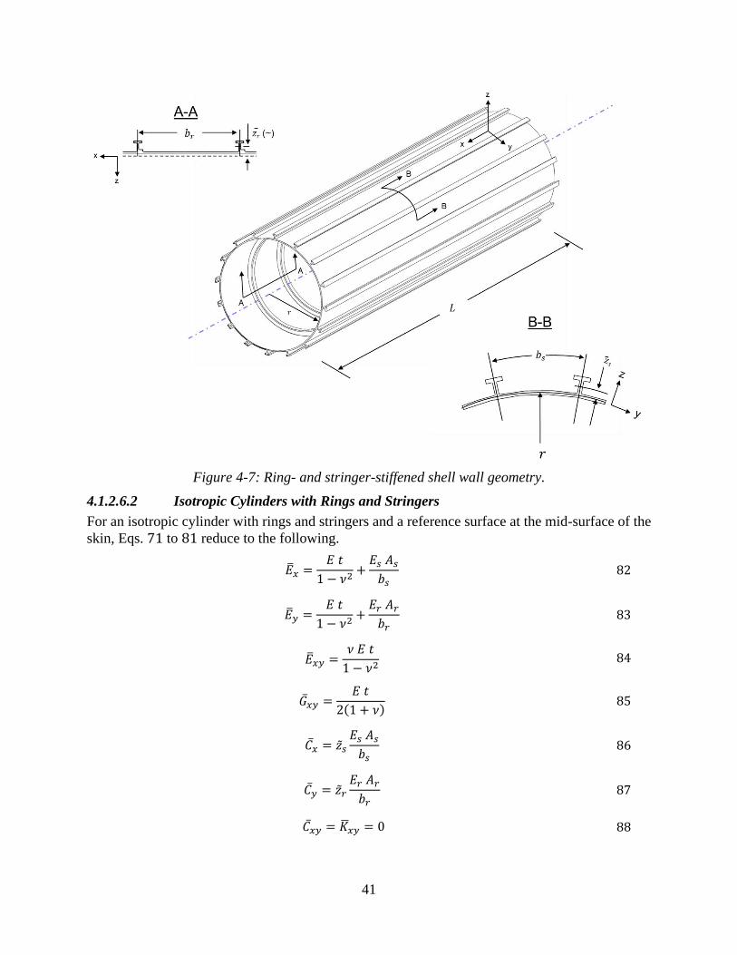
41
Figure 4-7: Ring- and stringer-stiffened shell wall geometry.
4.1.2.6.2 Isotropic Cylinders with Rings and Stringers
For an isotropic cylinder with rings and stringers and a reference surface at the mid-surface of the
skin, Eqs. 71 to 81 reduce to the following.
��𝑥 =𝐸 𝑡
1 − 𝜈2+
𝐸𝑠 𝐴𝑠
𝑏𝑠 82
��𝑦 =𝐸 𝑡
1 − 𝜈2+
𝐸𝑟 𝐴𝑟
𝑏𝑟 83
��𝑥𝑦 =𝜈 𝐸 𝑡
1 − 𝜈2 84
��𝑥𝑦 =𝐸 𝑡
2(1 + 𝜈) 85
𝐶�� = ��𝑠
𝐸𝑠 𝐴𝑠
𝑏𝑠 86
𝐶�� = ��𝑟
𝐸𝑟 𝐴𝑟
𝑏𝑟 87
𝐶��𝑦 = 𝐾𝑥𝑦 = 0 88

42
��𝑥 =𝐸 𝑡3
12(1 − 𝜈2)+
𝐸𝑠 𝐼𝑠𝑏𝑠
+ ��𝑠2𝐸𝑠 𝐴𝑠
𝑏𝑠 89
��𝑦 =𝐸 𝑡3
12(1 − 𝜈2)+
𝐸𝑟 𝐼𝑟𝑏𝑟
+ ��𝑟2𝐸𝑟 𝐴𝑟
𝑏𝑟 90
��𝑥𝑦 =𝜈 𝐸 𝑡3
6(1 − 𝜈2)+
𝐸 𝑡3
6(1 + 𝜈)+
𝐺𝑠 𝐽𝑠𝑏𝑠
+𝐺𝑟 𝐽𝑟𝑏𝑟
91
4.1.2.6.3 Isotropic Isogrid-Stiffened Cylinders
A derivation of stiffness parameters for a general orthogonal stiffener pattern with diagonal
stiffener elements is presented in [196]. From that, stiffness parameters for the traditional waffle
grid pattern can be derived. In addition, a common stiffener pattern, somewhat related to the waffle
pattern, consisting of an equilateral triangle pattern, commonly referred to as an isogrid stiffener
pattern (see Figure 4-8).
The stiffnesses for isogrid-stiffened isotropic cylinders are given by
��𝑥 = ��𝑦 =𝐸 𝑡
1 − 𝜈2+
3√3
4
𝐸 𝐴𝑠
𝑎
92
��𝑥𝑦 =𝜈 𝐸 𝑡
1 − 𝜈2+
√3
4
𝐸 𝐴𝑠
𝑎
93
��𝑥𝑦 =𝐸 𝑡
2(1 + 𝜈)+
√3
4
𝐸 𝐴𝑠
𝑎 94
𝐶�� = 𝐶�� = ��𝑠
3√3
4
𝐸 𝐴𝑠
𝑎
95
𝐶��𝑦 = 𝐾𝑥𝑦 = ��𝑠
√3
4
𝐸 𝐴𝑠
𝑎
96
��𝑥 = ��𝑦 =𝐸 𝑡3
12(1 − 𝜈2)+
3√3
4
𝐸 𝐼𝑠𝑎
+√3
4
𝐺 𝐽𝑠𝑎
97
��𝑥𝑦 =𝜈 𝐸 𝑡3
6(1 − 𝜈2)+
𝐸 𝑡3
6(1 + 𝜈)+
3√3
2𝑎𝐸 𝐼𝑠 +
√3
2𝑎𝐺 𝐽𝑠 98
where a is the stiffener length.

43
Figure 4-8: Isogrid geometry definition. The fillet details in this figure are commonly found in
integrally stiffened metallic designs, however, effects of fillets are neglected in the stiffness
calculations.
4.1.2.6.4 Ring-Stiffened Corrugated Cylinders
The following equations are commonly used to calculate the elastic constants for ring-stiffened
corrugated cylinders [124]. These properties assume that each segment of the corrugation has the
length 𝑐 and pitch 𝑗. The corrugated shell geometry definition is given in Figure 4-9.
��𝑥 = 𝐸𝑡 99
𝑡 =2 𝑡𝑐
1 + 𝑐𝑜𝑠 𝜒 100
��𝑦 =𝐸𝑟 𝐴𝑟
𝑏𝑟 101
��𝑥𝑦 = 𝐺 𝑡𝑐 (𝑡𝑐𝑡) 102
��𝑥 = 𝐸 𝐼 103
𝐼 =𝑡𝑐 𝑗
2
3(
𝑠𝑖𝑛2 𝜒
1 + 𝑐𝑜𝑠 𝜒) 104
��𝑦 =𝐸𝑟 𝐼𝑟𝑏𝑟
+ ��𝑟2 𝐸𝑟 𝐴𝑟
𝑏𝑟 105

44
��𝑥𝑦 =𝐺𝑟 𝐽𝑟𝑏𝑟
106
𝐶�� = ��𝑟
𝐸𝑟 𝐴𝑟
𝑏𝑟 107
��𝑥𝑦 = 𝐶�� = 𝐶��𝑦 = 𝐾𝑥𝑦 = 0 108
Figure 4-9: Corrugated shell geometry definition
Other Design Considerations in Stiffened Cylinders
4.1.2.7.1 Local Skin Buckling
In some stiffened cylinder designs, the skin may buckle before the global buckling and collapse of
the cylinder. A buckled skin is less stiff than an unbuckled skin. The decreased stiffness can be
calculated by methods similar to those presented in [120, 126, 197] and incorporated in the global
buckling calculation. In some designs, local bending associated with the bending boundary layer
response at the end of the cylinder or local bending near stiffness discontinuities can cause
premature skin buckling. This type of local skin buckling is typically identified in the detailed
design phase by using geometrically nonlinear analyses of detailed FEMs. Mass allowances
typically cover any additional reinforcement required to mitigate this buckling response if
necessary. In other cases, local skin buckling may be intentionally allowed so that skin thicknesses
may be decreased to further reduce weight.
4.1.2.7.2 Effects of Smeared Stiffener Approximation
In general, the smeared stiffener theory is often adequate in the preliminary design of cylinders.
The predicted linear bifurcation buckling load with this assumption is generally valid for closely
spaced stiffeners. Some cases have been identified where the effects of discrete stiffeners on the
buckling response must be assessed [25], especially in cases where stiffeners exhibit out-of-plane
deformations (i.e., rolling), local skin deformations between the stiffeners leads to a loss of
stiffness in the cylinder, or nonlinear interactions between local and global deformations. Such
situations may arise in the prebuckling range of loading of the cylinder near cutouts, joints, or
other stiffness discontinuities in the cylinder. The loss of effective stiffness of the stiffener or skin
can invalidate the smeared stiffener approximation.
Isotropic Sandwich Cylinders
The term isotropic sandwich refers to a layered construction formed by two thin isotropic
facesheets separated by a thicker core. Generally, the thin facesheets provide most of the bending
stiffness of the construction. The core separates the facesheets and provides the transverse shear
stiffness of the sandwich construction.

45
Sandwich construction should be checked for two possible modes of instability failure:
(1) general instability, i.e., global buckling, where the shell fails with the core and facesheets acting
together, and (2) local instability failure taking the form of facesheet dimpling or wrinkling (see
Figure 4-10).
Figure 4-10: Types of failure in sandwich shells.
If the isotropic sandwich cylinder has thin facesheets, and the core with core height h. The core
has relatively low bending stiffness, then for unequal thickness facesheets, the bending stiffness is
given by
𝐷1 =𝐸 𝑡1 𝑡2 ℎ
2
(1 − 𝜈2)(𝑡1+𝑡2) 109
and for equal thickness facesheets by
𝐷1 =𝐸 𝑡𝑓 ℎ2
2(1 − 𝜈2) 110
The extensional stiffness for unequal thickness facesheets is given by
𝐵1 =𝐸
(1 − 𝜈2)(𝑡1+𝑡2) 111
and for equal thickness facesheets by
𝐵1 =2 𝐸 𝑡𝑓
(1 − 𝜈2) 112
The transverse shear stiffness for an isotropic core and unequal thickness face sheets is given by
𝐷𝑞 = 𝐺𝑥𝑧
ℎ2
(ℎ −(𝑡1+𝑡2)
2)
113
General buckling Dimpling
of facesheetsWrinkling of facesheets
Core
Facesheet
Facesheet
Honeycomb
core
Separation
from coreCore crushing

46
and for equal thickness facesheets by
𝐷𝑞 = 𝐺𝑥𝑧
ℎ2
(ℎ − 𝑡𝑓) 114
The stiffnesses of other types of sandwich construction are given in [196, 198, 199, 200, 201].
Axial Compression
The buckling response of isotropic sandwich cylinders is similar to the response of unstiffened
isotropic cylinders described in Section 4.1.1.1, except that they can be heavily influenced by
transverse shear effects. For most practical unstiffened cylinders, the transverse shear stiffness is
relatively large compared to the bending stiffness of the cylinder wall, so transverse shear
deformations can be safely neglected in analysis. However, as the thickness of a sandwich structure
increases, the bending stiffness increases disproportionately to the transverse shear stiffness. This
results in the actual cylinder buckling at a lower load level than predicted by classical analysis that
neglects transverse shear.
Investigations into the buckling behavior of isotropic sandwich cylinders in axial compression
have been reported in [74, 75]. These references provide two methods for computation of the axial
buckling load of isotropic sandwich cylinders that consider the effect of transverse shear
flexibility. The design information from these references are given in Figure 4-11, Figure 4-12,
and Figure 4-13.
Method 1 is the corollary to Eq. 2 and Figure 4-1, and it uses the knockdown factor from Figure
4-13 and the buckling coefficient from Figure 4-11. It is only applicable when the longitudinal and
circumferential transverse shear stiffnesses are equal (𝐺𝑥𝑧
𝐺𝑦𝑧= 1.0).
The first step is to compute the knockdown using the ratio of the cylinder radius to the sandwich
wall thickness, 𝑟
ℎ, with the data presented in Figure 4-13. This knockdown factor is based Eq. 60,
given for orthotropic cylinders, with the parameter 𝜙 as
𝜙 =√2
29.8√
𝑟
ℎ 115
Once the buckling knockdown factor is calculated, it can be combined with the curvature
parameter, 𝑍, and the buckling coefficient can be obtained from Figure 4-11. Different curves are
provided for different values of transverse shear flexibility coefficient. 𝑅 is given by
𝑅 =𝜋2 𝐷1
𝐿2 𝐷𝑞 116
Method 2 is often more convenient, and it is applicable for
𝛾𝑍 >𝜋2
1 + 𝑅 117
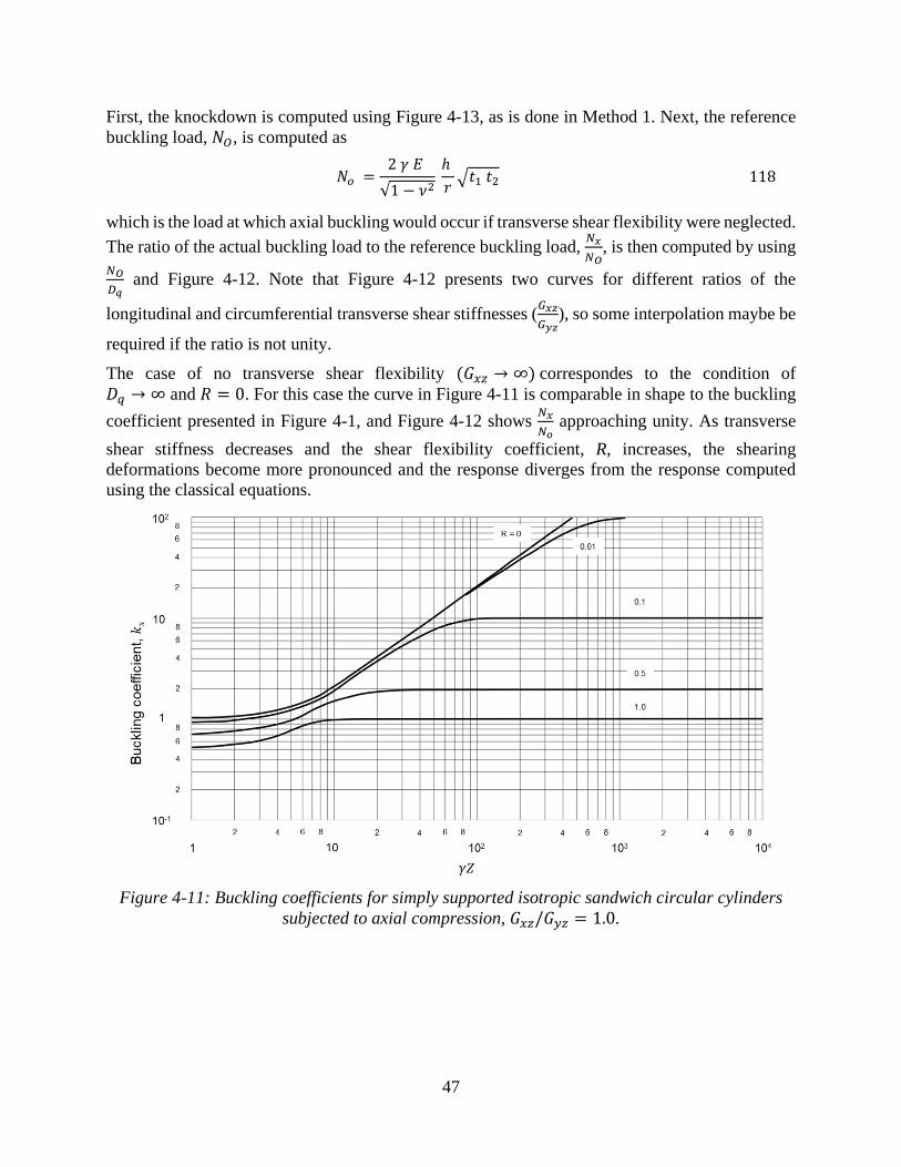
47
First, the knockdown is computed using Figure 4-13, as is done in Method 1. Next, the reference
buckling load, 𝑁𝑂, is computed as
𝑁𝑜 =2 𝛾 𝐸
√1 − 𝜈2 ℎ
𝑟√𝑡1 𝑡2 118
which is the load at which axial buckling would occur if transverse shear flexibility were neglected.
The ratio of the actual buckling load to the reference buckling load, 𝑁𝑥
𝑁𝑂, is then computed by using
𝑁𝑂
𝐷𝑞 and Figure 4-12. Note that Figure 4-12 presents two curves for different ratios of the
longitudinal and circumferential transverse shear stiffnesses (𝐺𝑥𝑧
𝐺𝑦𝑧), so some interpolation maybe be
required if the ratio is not unity.
The case of no transverse shear flexibility (𝐺𝑥𝑧 → ∞) correspondes to the condition of
𝐷𝑞 → ∞ and 𝑅 = 0. For this case the curve in Figure 4-11 is comparable in shape to the buckling
coefficient presented in Figure 4-1, and Figure 4-12 shows 𝑁𝑥
𝑁𝑜 approaching unity. As transverse
shear stiffness decreases and the shear flexibility coefficient, R, increases, the shearing
deformations become more pronounced and the response diverges from the response computed
using the classical equations.
Figure 4-11: Buckling coefficients for simply supported isotropic sandwich circular cylinders
subjected to axial compression, 𝐺𝑥𝑧/𝐺𝑦𝑧 = 1.0.

48
Figure 4-12: Buckling load scaling for moderately long, simply-supported, isotropic sandwich
circular cylinders subjected to axial compression.
Figure 4-13: KDFs for isotropic sandwich circular cylinders subjected to axial compression.
Sandwich plates with light honeycomb cores are susceptible to additional modes of deformation,
and failure may result from intracell buckling, facesheet wrinkling, or an interaction of one or both
modes with a global cylinder buckling mode. In addition, small buckle-like deformations have
been known to occur in actual structures long before the theoretical buckling load is reached. See,
for example, page 217 of [154]. This behavior requires that the structure be capable of resisting
internal moments and shears in addition to the directly applied loads. In the case of sandwich
cylinders, the moments and shears may cause buckling or shear failure of the core.
The only known method for preventing these core failures is to use relatively heavy cores, which
have considerable strength in crushing and shear. Some guidance as to how heavy the cores should
be can perhaps be gleaned from the bending tests that have been made on multi-web beams. The
0
0.1
0.2
0.3
0.4
0.5
0.6
0.7
0.8
0.9
1
10 100 1000
r/h

49
internal structure of these beams is subjected to the same types of loads as the cores of loaded
sandwich plates. One reference [202] indicates that honeycomb cores with a density ratio of 𝛿 = 0.03 should be adequate to prevent core failure. Large margins against failure in intracell
buckling and wrinkling can be obtained with rather heavy cores 𝛿 > 0.03 with little or no weight
penalty. Moreover, when heavy cores are used, approximate equations are adequate for predicting
failures in the intracell buckling and facesheet wrinkling modes. The following may be used for
this purpose. For intercell buckling [203, 204]:
𝜎𝑥 = 2.5 𝐸𝑅 (𝑡
𝑆)2
119
where 𝑆 is the core cell size and characterized as the diameter of the largest inscribed circle,
𝐸𝑅 =4 𝐸 𝐸𝑡𝑎𝑛
(√𝐸 + √𝐸𝑡𝑎𝑛)2 120
where 𝐸 and 𝐸𝑡𝑎𝑛 are the elastic and tangent moduli of the facesheet material, respectively. If
initial facesheet dimpling is to be checked, the following equation should be used:
𝜎𝑥 = 2.2 𝐸𝑅 (𝑡
𝑆)2
121
The sandwich will still carry the load if initial dimpling occurs.
Critical wrinkling stresses are predicted by [154, 201] as
𝜎𝑥 = 0.50 (𝐸𝑠𝑒𝑐 𝐸𝑧 𝐺𝑥𝑧)13
122
where 𝐸𝑧 is the modulus of the core in the direction perpendicular to the core and 𝐺𝑥𝑧 is the
transverse shear modulus of the core in the x-z plane. Here Esec is the secant modulus of the core.
If biaxial compressive stresses are applied to the sandwich, then the coefficients of the equations
must be reduced per [205] by the factor
(1 + 𝑓3)−13
123
where
𝑓 =minimum principal compressive strain in facesheets
maximum principal compressive strain in facesheets 124
Wrinkling and intracell buckling equations, which consider strength of bond, strength of
foundation, and initial waviness of the facesheets are given in [203, 206, 207].
The plasticity correction factors given in Eqs. 11 and 12 for isotropic cylinders in axial
compression may also be applied to isotropic sandwich cylinders. The factor is applicable to
sandwich cylinders with stiff cores and becomes somewhat conservative as the shear stiffness of
the core is decreased [208].
Bending
The buckling equations given in Section 4.1.1.1 for circular cylinders in axial compression may
be used for cylinders in bending, provided the knockdown factor 𝛾 is taken from Figure 4-14. The
knockdown factor curve in Figure 4-14 is based on Eq. 62, given earlier for orthotropic cylinders
in bending.

50
Figure 4-14: Knockdown factors for isotropic sandwich cylindrical shell subjected to bending.
Lateral Pressure
A plot of buckling coefficient 𝑘𝑦 as a function of 𝛾𝑍, based on data from [209], is given in Figure
4-15. The straight-line portion of the curve in Figure 4-15 for a sandwich cylinder with rigid core (𝑅 = 0) is given by the equation
𝑘𝑦 =𝑁𝑦𝐿2
𝜋2𝐷1= 0.56√𝛾𝑍 125
There are no experimental data to substantiate Figure 4-15; experience with isotropic cylinders,
however, suggests that a knockdown factor 𝛾 = 0.56 should be used with this configuration.
Figure 4-15: Buckling coefficients for isotropic sandwich circular cylinders subjected to lateral
pressure and 𝐺𝑥𝑧
𝐺𝑦𝑧= 1.0.
Here, as with sandwich cylinders in axial compression or bending, designs should be limited to
sandwich cylinders for which the density ratio 𝛿 > 0.03, unless the design is substantiated by tests.

51
The plasticity factors for isotropic cylinders subjected to external pressure, expressed by Eqs. 30-
32, may be used for isotropic sandwich cylinders subjected to lateral pressure.
Torsion
Isotropic sandwich cylinders in torsion have not received the same attention as cylinders in
compression. Rigid- and weak-core cases are reasonably well defined. While the transition
between rigid and weak core is not well defined, it is probably enough for design purposes.
Information on the transition region is given in [209, 210], the latter of which was used to construct
the plot shown in Figure 4-16, which applies to sandwich cylinders with core exhibiting isotropic
shear behavior 𝐺𝑥𝑧
𝐺𝑦𝑧= 1.0. The slopes curves in Figure 4-16 are continuous at the value of 𝛾𝑍 where
the buckling coefficient 𝑘𝑥𝑦 become equal to 1
𝑅 (or the inverse of the shear flexibility coefficient),
associated with a change in buckling mode at that point. In [210], the aforementioned behavior is
not supported, but it does not cover a sufficiently wide range of geometric proportions. In addition,
[210] indicates that there was some scatter in the calculated results used to construct the charts in
that reference. In the ranges where comparisons between data could be made, only relatively small
discrepancies were noticed [209, 210]. The straight-line portion of the curve in Figure 4-16 for a
rigid core (𝑅 = 0) is given by the equation
𝑘𝑥𝑦 =𝑁𝑥𝑦 𝐿2
𝜋2 𝐷1= 0.34(𝛾𝑍)
34⁄ . 126
Experimental data are not available to substantiate Figure 4-16 for most sandwich cylinders.
Experience with isotropic cylinders suggests that a knockdown factor 𝛾 = 0.586 should be used
with this figure. Here, as with sandwich cylinders in axial compression or bending, designs should
be limited to sandwich cylinders for which the density ratio 𝛿 > 0.03 or greater, unless the design
is substantiated by tests. \
Figure 4-16: Buckling coefficients for isotropic sandwich circular cylinders subjected to torsion
and 𝐺𝑥𝑧
𝐺𝑦𝑧= 1.0.

52
The plasticity factor for isotropic cylinders subjected to torsion, expressed by Eq. 40, may be used
for isotropic sandwich cylinders subjected to torsion.
Cylinders with an Elastic Core
The term cylinder with an elastic core refers to a thin-walled cylindrical shell that encloses an
elastic material that can be either solid or have a hole in its center. This type of cylinder closely
approximates a propellant-filled missile or solid rocket motor. Only the solid propellant is typically
a viscoelastic material and therefore is strain-rate sensitive. The core modulus should be obtained
from tension or compression test of the core material simulating its expected strain rate.
Although there are some analytical data for orthotropic shells [211], design curves are given only
for isotropic shells and cores. The inverse problem of a cushion or foam material on the outside of
the cylinder is analyzed in [212]. Not enough data are available, however, to recommend design
curves for this problem.
Axial Compression
The buckling of isotropic cylindrical shells with a solid elastic core in axial compression is
presented in [213]. This solution conservatively assumes that the axial load is carried entirely by
the cylinder and that the effect of the core is to increase the bending stiffness of the cylinder wall.
Thus, the effect of the core is to increase the axial stress in the cylinder wall at which buckling
occurs, 𝜎𝑝, relative to a cylinder without a core, 𝜎𝑐. The core is assumed to be isotropic, with
modulus of elasticity 𝐸𝑐 and Poisson’s Ratio 𝜈𝑐. Analytical results obtained from this reference are
shown graphically in Figure 4-17. For small values of 𝜙1
𝜎𝑝
𝜎𝑐≈ 1 + 𝜙1 127
where this quotient is the stress for the combined cylinder-core system relative to the stress that
would be in a cylinder without an elastic core, and
𝜎𝑐 =𝛾𝐸
√3(1 − 𝜈2)
𝑡
𝑟 128
𝜙1 =√12(1 − 𝜈2)4
4(1 − 𝜈𝑐2)
𝐸𝑐
𝐸 (
𝑟
𝑡)
32
129
This approximation is accurate for 𝜙1 < 0.5. For larger values of 𝜙1, say 𝜙1 > 3.0, Eq. 127
becomes
𝜎𝑝
𝜎𝑐≈
3
2(𝜙1)
23 130
The experimental data provided in [213] suggest that the KDF 𝛾 in Eq. 128 can be taken as that
for isotropic cylinders in compression as in Eqs. 9 and 10.
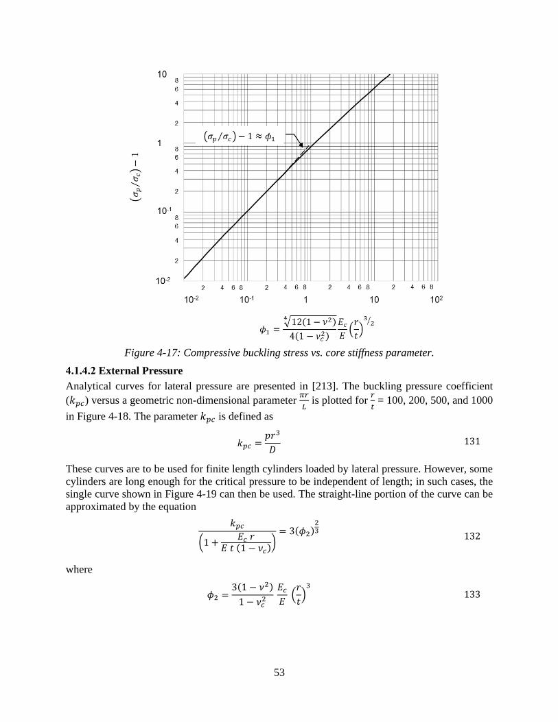
53
Figure 4-17: Compressive buckling stress vs. core stiffness parameter.
External Pressure
Analytical curves for lateral pressure are presented in [213]. The buckling pressure coefficient
(𝑘𝑝𝑐) versus a geometric non-dimensional parameter 𝜋𝑟
𝐿 is plotted for
𝑟
𝑡 = 100, 200, 500, and 1000
in Figure 4-18. The parameter 𝑘𝑝𝑐 is defined as
𝑘𝑝𝑐 =𝑝𝑟3
𝐷 131
These curves are to be used for finite length cylinders loaded by lateral pressure. However, some
cylinders are long enough for the critical pressure to be independent of length; in such cases, the
single curve shown in Figure 4-19 can then be used. The straight-line portion of the curve can be
approximated by the equation
𝑘𝑝𝑐
(1 +𝐸𝑐 𝑟
𝐸 𝑡 (1 − 𝜈𝑐))
= 3(𝜙2)23 132
where
𝜙2 =3(1 − 𝜈2)
1 − 𝜈𝑐2
𝐸𝑐
𝐸 (
𝑟
𝑡)3
133

54
Figure 4-18: Variation of buckling pressure coefficient with length and modulus ratio
(𝜈 = 0.3, 𝜈𝑐 = 0.5).

55
Figure 4-19: Buckling pressure coefficients for long cylinder with an elastic core.
Torsion
The buckling behavior of cylindrical shells with an elastic core subjected to a torsion load is
presented in [214] and is shown graphically in Figure 4-20.
For small values for 𝜙3 < 7, the analytical results can be approximated by
𝜏
𝜏𝑐𝑟= 1 + 0.16 𝜙3 134
where
𝜙3 = (𝐸𝑐
𝐸) (
𝐿
𝑟) (
𝑟
𝑡)2
135
and 𝜏𝑐𝑟 is torsional buckling stress given by Eq. 34, with the correlation factor 𝛾 equal to unity.
When 𝜙3 is > 10, the analytical results follow the curve
𝜏
𝜏𝑐𝑟= 1 + 0.25 𝜙3
34 136
Experimental data are not available for this loading condition. The experimental points obtained
for cylinders with elastic core for axial compression and external pressure, however, show better
correlation with theory than the corresponding hollow cylinders. Hence, conservative design
curves can be obtained by calculating 𝜏𝑐𝑟 in Eqs. 134 and 136 with the correlation and plasticity
factors for isotropic cylinders of Eqs. 30-32.

56
Figure 4-20: Torsional buckling coefficients for cylinders with an elastic core.
Combined Axial Compression and External Pressure
Interaction curves for cylinders with an elastic core subjected to combined axial compression and
lateral pressure are shown in Figure 4-21. These curves were obtained analytically in [213] and
indicate that for sufficiently stiff core, the critical axial stress is insensitive to the lateral pressure
and, similarly, the critical lateral pressure is insensitive to the axial compression. However, until
more experimental data become available, the use of a straight-line interaction curve is
recommended for conservative design.
Figure 4-21: Interaction curves for cylinders with an elastic core (𝑟
𝑡= 300).

57
Other Design Considerations
Joints
A limited amount of information is available in the open literature on the design of joints in
buckling-critical cylinders. However, a detailed study on the effects of axial weld lands, and to a
lesser extent, circumferential weld lands has been conducted for large-scale cylinders [90, 213].
Results in [90] indicate that axial weld lands in large-scale compression-loaded orthogrid-stiffened
cylinders can lead to a significant reduction in the buckling load on the order of 25% or more. The
general conclusion from the study was that the weld land region has relatively high membrane
stiffness compared to the stiffened acreage, typically composed of thin skin and tall stiffeners.
However, because of low bending resistance, the weld land buckles at much lower load levels than
the stiffened acreage.
Since axial and circumferential joints can generally pose a buckling concern, joint designs or local
stiffness tailoring that delay the onset of buckling should be sought. This can include the
development of a stiffness-neutral joint such as a scarf joint when joining composite sandwich
panels together. The stiffness-neutral joint concept attempts to provide a joint between two
adjacent cylindrical panels while minimizing discontinuities in stiffness, or load-path/mid-surface
eccentricities. If a stiffness-neutral joint design option is not available or practical, as may be the
case in welded metallic construction, local bending stiffness can be increased by adding additional
stiffeners adjacent to the joint, e.g. additional axial, circumferential or diagonal stiffeners. In
particular, the addition of diagonal stiffeners adjacent to an axial weld land has been found to be
particularly effective in delating the onset of buckling by providing additional twisting stiffness.
Increasing the thickness of the weld land does not always result in an improvement, but rather, can
attract more load and reduce the buckling load further.
Cutouts
Experimental results have shown that small cutouts have minimal effect on the buckling response
of cylinders, since other imperfections govern the global buckling response of the shell. For cutouts
whose width is less than approximately 10 percent of the cylinder diameter and whose height is
less than approximately 20 percent of the cylinder height, the empirically-based equations of
Section 4.1 are sufficient for the preliminary design of the cylinder. However, the designer should
expect the structure to require some reinforcement around the cutout to control local stresses and
deformations. Reinforcement concepts should be designed to control local displacement and stress
concentrations near the cutout to within allowable values while maintaining a smooth transition
from the reinforcement to the acreage. Designs should avoid abrupt stiffness changes and load path
eccentricities to prevent localized failures such as buckling adjacent to the reinforcement. The
reinforcement should also be tailored to prevent the detrimental effects of prebuckling
displacements, which are known to instigate buckling at load levels lower than predicted with the
classical buckling load value. For larger cutout sizes, this approach may still be used, but it
becomes increasingly difficult to reinforce the cutout to compensate for the larger changes in stress
distribution in the cylinder walls and to restore the cylinder to full load-carrying capacity. Further,
if the cutout is sufficiently large, the buckling response of the structure reaches a point that it can
no longer be described as cylinder buckling and geometrically nonlinear finite-element methods
are required to predict the buckling load. Thus, an analysis approach, as described in Section 4.3,
is recommended for cylinders with large cutouts.

58
Design of Ring Frames
Limited amount of information is available in the open literature on the design of stiff ring frames
for cylinders. The criterion from [201] is frequently cited as applicable to cylinders subjected to
bending or compression loads. Unfortunately, this criterion is empirical and is based on data from
test cylinders with configurations that are not often relevant to the design of modern vehicles. A
few verifications made on cylinders in use have indicated that the criterion is usually conservative,
but this may not be so in certain cases [162, 215].
A less direct procedure for designing rings may be used. The procedure consists of calculating the
global buckling response (i.e., general instability), which involves failure of the rings and cylinder,
as well as calculation of the buckling response of the cylinder between the rings (inter-ring
buckling). Both calculations are made for several ring configurations. The buckling loads are then
plotted against ring weight (structural efficiency curves), and the ring design and weight necessary
to produce the desired mode can be determined. It is likely that there may be some interaction
between failure modes; thus, somewhat heavier rings than those indicated by the calculations
should be used. These interactions should be assessed by using a geometrically nonlinear analysis
and validated through suitable testing as necessary.
This method of designing rings is, of course, applicable to all types of loading and to all types of
wall construction. The method also has the advantage of giving the designer some feeling for the
influence of the various factors that determine the ring weight.
A review of [215, 216], which present general linear analyses of ring-stiffened isotropic cylinders
in torsion and of orthotropic cylinders in compression, indicates that the recommended procedure
gives the same result as general theory for all cylinders except those with a single ring dividing
the cylinder into two equal-length bays.
4.2 Semi-Empirical Design Approach
In 1970, Almroth et al. proposed a semi-empirical design approach for compression-loaded
cylindrical shells in an attempt to incorporate knowledge that had been acquired from the
1940s−1960s into the design process [12]. These research efforts led to a good understanding of
the basic reasons for the poor correlation between the theoretical buckling loads and the
corresponding test loads, but that results from that research had “not been utilized to devise better
methods for practical analysis.” Furthermore, for orthotropic/composite shells, stiffened shells,
and other practical cylinder configurations, the number of design parameters becomes so large that
a purely empirical design approach becomes infeasible. Thus, a semi-empirical design approach
was developed based on [9] in combination with a wide-column buckling investigation in [119].
This approach has been used successfully in the design of several aerospace structures over the
years. A brief summary of this Semi-Empirical Design Approach (per the definition included in
the front-matter) is presented in this section.
Assumptions
This Semi-Empirical Design Approach assumes that initial geometric imperfections in the shell
wall are the primary reason for the discrepancy between theory and test. The assumptions in this
theory are that the initial imperfection is axisymmetric and of small amplitude. Additionally, it is
assumed that both the Koiter method and the wide-column buckling approach produce
conservative estimates of the buckling load and that the higher of the two predictions is to be used
as the design buckling load.

59
Approach
For any given cylindrical shell being analyzed, an equivalent monocoque cylinder is defined in
terms of an effective radius-to-thickness ratio, (𝑟
𝑡)𝑒, where
(𝑟
𝑡)𝑒
= 0.289
[
𝑟
√��𝑥��𝑦
��𝑥��𝑦
4
]
137
An empirical knockdown factor that corresponds to a given (𝑟
𝑡)𝑒 can be calculated using Eq. 9 or
Eq. 14 for cylinders subjected to axial compression or bending, respectively. This knockdown
factor is then used to calculate a normalized imperfection amplitude 휀 that would cause the same
reduction in buckling load based on the curve presented by Koiter [9], and shown in Figure 4-22
for ν = 0.3. 휀 represents the ratio of imperfection amplitude to effective wall thickness. The
relationship between 𝛾 and 휀 is given by
𝛾 = 1 + 𝛼 휀 − √𝛼 휀 (2 + 𝛼 휀), 138
where
𝛼 = 3
4 √3(1 − 𝜈2)
139
Figure 4-22: Knockdown factor from Koiter's theory based on small deviation imperfection when
normalized to wall thickness for conditions when 𝜈 = 0.3.
It is then assumed that the cylinder under consideration has the same imperfection amplitude as
the equivalent cylinder and a design buckling load can then be calculated using the analysis for
imperfect cylinder as described by Almroth (see Appendix A of [12]).
Almroth found however, that this analysis approach had limitations and was overly conservative
when applied to core-filled cylinders and short stringer-stiffened (i.e., axially stiff) cylinders and
that the wide-column buckling load predictions, as proposed by Peterson and Dow, were more
applicable. Thus, it is recommended that the wide column buckling load also be calculated and
0
0.1
0.2
0.3
0.4
0.5
0.6
0.7
0.8
0.9
1
0 0.1 0.2 0.3 0.4 0.5 0.6 0.7 0.8 0.9 1
e

60
compared to the Semi-Empirical Approach, with the larger of the two values being used as the
design buckling load. This Semi-Empirical procedure is summarized in a flow chart in Figure 4-23.
A general process flow for calculating buckling loads with this method is presented below in
Figure 4-23. Here are the steps that need to be followed:
(1) Calculate an equivalent (𝑟
𝑡)𝑒 for the design in question using Eq. 137.
(2) Using this equivalent (𝑟
𝑡)𝑒, calculate the appropriate knockdown factor, 𝛾, for axial or bending
loading conditions of an equivalent isotropic cylinder.
(3) Next, calculate the normalized imperfection amplitude, 휀, using Eq. 138 that corresponds to
the knockdown factor calculated from step 2.
(4) With this imperfection amplitude, calculate the cylinder buckling load and the wide column
buckling load using Appendix A of [12].
(5) The buckling load should be chosen as the higher of the two buckling predictions, both buckling
loads are expected to be conservative [12].
Figure 4-23: Process for calculating the buckling load using Almroth’s Semi-Empirical
Approach.
4.3 Analysis-Based Design Approach
Analysis-based buckling load predictions can be a viable alternative to Empirical and Semi-
Empirical Approaches presented in Sections 4.1 and 4.2, respectively. In particular, improved
nonlinear structural analysis tools, improved theories of elastic stability and imperfection
sensitivity in shell structures, and advanced testing and measurement technologies are enabling
realistic buckling load predictions of thin-walled shell structures. Thus, high-fidelity numerical
Calculate KDF:
Bending:
Axial:
Calculate equivalent monocoque
radius-to-thickness ratio:
Buckling Load = Max {P1 , P2}
Calculate e (imperfection amplitude/ wall thickness) with Koiter’s equation:
Calculate wide column buckling load (P1) and cylinder buckling load (P2) from
𝛾 = 1 − 0.731 1 − 𝑒−𝜙

61
simulations can be used in place of physical tests and provide a more accurate and less conservative
estimate of the actual buckling load. However, thorough model development and validation are
required to ensure that the model adequately and correctly represents the physics of the structural
response. While accuracy of the prediction can be defined on a case-by-case basis to meet specific
program needs, it is generally recommended that the high-fidelity model should provide buckling
load predictions to within ±10% of the validation test loads and capture the overall character of
the response and failure mode.
These high-fidelity simulations can be used to (1) Design a structure to a desired buckling load,
and then can be used to calculate design margins for buckling or strength, or (2) Develop new
analysis-based KDFs for a family of designs that exhibit similar behavioral characteristics and
share similar manufacturing processes and controls and imperfection signatures.
The recommended approach used in the development and validation of these high-fidelity models
and simulations and there use in an analysis-based design approach is presented next.
Model Development
Recommended procedures and considerations for developing finite-element-based high-fidelity
models are presented in this section. These recommended procedures are not a replacement for
sound engineering judgement and experience. These recommended procedures can be modified as
needed if supported by technical rational and/or by physical testing. While all discussions are
related to the development of finite element-based models, this does not preclude the use of other
modeling techniques if they provide similar levels of fidelity.
Overview
To develop a high-fidelity model of the buckling response of a thin-walled cylinder subjected to
combined mechanical, pressure and thermal loads, the model shall accurately predict all relevant
structural response characteristics up to and including the buckling of the cylinder. For example,
effective stiffness (i.e., load versus end-displacement response), prebuckling and buckling
displacement and strain response, buckling mode, and the buckling load.
The accuracy of the model is naturally limited by how well the structural details are known, e.g.,
geometry, material properties, and loading and boundary conditions, and how well the details are
represented in the model. Thus, the development of a high-fidelity model will require additional
information on the cylinder and thorough model development and validation beyond what is
required for the Empirical and Semi-Empirical Design Approaches defined in Sections 4.1 and
4.2. The model development is presented in the following subsections. Suggested model validation
methods and metrics are discussed in Section 4.3.2.
Structural Idealization
Structural idealization is the process of converting the physical design into a mathematical
representation. Details that can significantly influence the buckling response, stiffness, loads and
load paths, and local and global deformations should be assessed carefully. Some examples of
common modeling details and considerations are described here.
For the majority of thin-walled unstiffened and stiffened cylinders considered in this monograph,
2D shell elements are sufficient to accurately model the elastic cylinder buckling response.
However, it is almost always required that discrete stiffeners and other flexible structural
components that contribute to or influence the overall structural behavior need to be modeled
explicitly. The smeared stiffener theory is often inadequate for the development of a high-fidelity

62
model as the flexibility of the individual stiffener and skin elements can significantly influence the
prebuckling and buckling response. Modeling stiffeners and other detail features explicitly enable
accurate predictions of the interaction between local and global effects. Local detail features such
as fillets are often ignored in lower-fidelity design-level models; however, they may contribute
additional stiffness necessary to accurately model local or global displacement and stiffness
responses, especially if the fillet radius is large relative to other structural element dimensions.
Examples and modeling strategies are presented in reference [217]. In general, however, modeling
local features such as fillets is typically reserved for detailed test and analysis correlation activities
and are typically not required for developing design buckling load predictions.
Material overlap should be minimized at 2D shell element intersections as it adds additional local
stiffness and mass. Shell wall mid-surface offsets should be incorporated into the model to
represent any mid-surface eccentricities such as those associated with local reinforcements or
thickness changes as these contribute to local bending, load redistribution, and premature buckling.
Stiffness discontinuities should be modeled. Discontinuities include cutouts, structural joints, or
large load-bearing secondary structures. Proper modeling of joint stiffness may require additional
subcomponent test or detailed models to assess the adequacy of the modeling approach especially
for bolted joints, attachments, and interfaces. Bolted or riveted connections can be modeled as
smeared or discrete connections. However, if used, the adequacy of the smeared modeling
approach should be assessed and may require detailed subcomponent models or tests if inter-rivet
or inter-bolt buckling, flexibility, or movement is expected.
Adjacent structures to the component of interest can be simulated using lower-fidelity models as
long as they produce an adequate representation of load paths and interface flexibility, including
membrane and bending flexibility.
A hierarchical or building-block approach is recommended for model development. A basic
uniform cylinder should be modeled and analyzed first, and the results compared to known closed-
form solutions. From here, additional structural details can be added knowing that the foundational
model is adequate, and the analyst has some basis for comparison when more complex details and
loading conditions are added to the model. If there is some uncertainty in the structural details
(e.g., their design and/or modeling), then it is recommended that a sensitivity study be conducted
to determine the effects of these uncertainties and provide bounds to the predicted response. It may
also be found over time and with experience, that certain structural details can be simplified or
omitted if the end result provides a reasonable and conservative estimate of the buckling response.
Discretization
The discretization process, which is equivalent to finite-element meshing, includes choosing
element type, element shape, element distribution, etc. A list of common discretization
considerations are as follows:
The majority of thin-walled cylinder buckling problems can be treated using standard linear or
quadratic quadrilateral shell elements. Elements with transverse shear capability are often
necessary for sandwich cylinders or cylinders that may exhibit localized out-of-plane
deformations, for example, short wave length displacement responses near cutouts and other
significant stiffness discontinuities or cylinders with discrete stiffeners that may exhibit local
rotations relative to the cylinder skin. Triangular shell elements may also be used but in the past

63
have been shown to possess some undesirable characteristics due to shear locking. Thus, higher-
order triangular elements can be used to minimize the effects of shear locking.
When stiffeners are explicitly modeled the choice of using either shell or beam elements should
be investigated to ensure compatible deformations between the stiffening element and the skin.
For sandwich cylinders with relatively thick core and a high degree of transverse shear flexibility,
standard 2D shell elements with transverse shear flexibility might not be adequate. These models
may require the use of other element types such as special-purpose sandwich elements, or a
combination of 2D and 3D elements to model facesheets and core material.
Ultimately, the choice of elements and spatial distribution necessary for a high-fidelity buckling
simulation should be determined and justified through a systematic study or based on relevant past
experience. Closed-form solutions should be used in the early stages of model development when
possible for comparison with the FEM. Additionally, a large-scale detailed FEM does not equate
to a high-fidelity FEM. The former implies the use of many finite elements. The latter implies that
the mathematical model adequately and correctly represents the physics of the systems for its
intended purpose.
Material Properties
The material properties and material model selected is a function of the material form and the
anticipated structural response of the cylinder. The basis of the material model, the required
material data for input, and the limitations of the material model need to be understood.
For elastic buckling simulations of metallic cylinders, linear elastic isotropic material properties
are often assumed and are typically adequate. However, there are certain high-performance alloys
that exhibit bi-modulus properties, that is, different tension and compression moduli. The effects
of bi-modulus materials on the buckling response will be a function of the loading conditions and
the relative difference between the tension and compression moduli. If the prebuckling response
of the cylinder results in local stresses that approach the yield strength of the material, then an
elastoplastic or elastic perfectly plastic material model may be required to account for local
material yielding and load redistribution.
Cylinders constructed from laminated composite materials such as graphite-epoxy have been
shown to exhibit nonlinear elastic prebuckling stiffness behavior. The nonlinearity can be a result
of matrix nonlinearity, as seen in angle-ply laminates, or fiber nonlinearity [218, 219]. These
nonlinearities can be accounted for by using a nonlinear elastic material model with data
determined from coupon testing. Laminated composite structures can also possess orthotropic or
anisotropic stiffness properties that depend on the laminate stacking sequence and can be
particularly important to the buckling and imperfection sensitivity of thin-walled cylinders, as
described in Section 4.1.2.
High-fidelity model development will typically require coupon test data obtained from witness
panels or tag ends from the tested cylinder in order to provide the most accurate set of material
properties and to verify the adequacy of the material model. If these data are not available, then a
sensitivity study should be conducted to bound the predicted response characteristics based on
existing material property data.
Boundary Conditions
In general, models will incorporate either an analytical definition of the boundary conditions
(e.g., classical clamped or simple support) or an explicit modeling of the interface/boundary

64
conditions and adjacent structure. In a design setting, conservative analytical boundary conditions
are often utilized and are appropriate. However, for most high-fidelity buckling simulations such
as those used for detailed test and analysis correlation or the development of analysis-based design
buckling loads, the modeling of the actual adjacent structure may be necessary to properly account
for structure to structure interactions that may influence load introduction, interface flexibility
(e.g., bolted, bonded, or potted joints), and overall system kinematics [217]. In addition, modeling
approaches that can simulate nonuniform loading due to geometric imperfections at the interfaces
(i.e., interface surface geometry variations due to manufacturing tolerances that results in gaps
between the interfaces) may need to be implemented. It is also conceivable that joints that have
contacting surfaces that can open and close as a function of loading may also require the use of
contact elements. Nonuniform loading due to loading surface imperfections will be discussed in
more detail in Section 4.3.1.7. The level of detail required is contingent on the end use and level
of fidelity required.
Loading Conditions
Modeling test loading conditions are typically straightforward as long as the test interfaces and
loading structure are understood, characterized, and modeled adequately. As discussed previously,
many high-fidelity models will require accurate models of the boundary conditions and adjacent
structure, and in the case of a structural test, representations of the load fixtures and discrete load
application points should be available for load application. However, if additional secondary loads
are applied directly to the cylinder, e.g., lateral loads to simulate internal payloads, or external
booster loads, then the representation of these point loads and local affects should be addressed.
Modeling complex flight loading conditions that include vehicle accelerations, aerodynamic
pressure, thermal loads, and cryogenic fuel slosh loads are altogether different as they are
associated with surface load distributions and body forces. As such, care must be taken in applying
these distributed loads onto a discretized model [41].
In both cases, test loading conditions and flight loading conditions, problems involving load
sequencing for combined loads, deformation dependent loading (follower loads), and quasi-static
versus transient-dynamic and time-dependent loading, may also arise.
Initial Imperfections and Loading Nonuniformities
Initial geometric and thickness imperfections (i.e., manufacturing-process-induced variations in
the as-built geometry) and loading nonuniformities due to interface surface geometry variations
can have a significant influence on the buckling response of thin-walled cylinders (see Section
2.2 and Section 2.3). Efforts have been made to characterize these imperfections and
nonuniformities in order to establish characteristic imperfection signatures that are associated with
different cylinder manufacturing processes. With this information established, high-fidelity
buckling analyses and robust design criteria can be developed. It is now standard practice to
measure these imperfections as part of any structural test campaign and they are typically used to
verify that the manufactured part meets the design requirements as well as provide data for the
development of detailed structural models. As-built geometry of complex structures can be
measured routinely by using commercially available geometry measurement systems such as
structured light scanners, laser trackers, or coordinate measurement machines. The resulting
measurement data can be included in finite-element models by using simple user-written scripts
or subroutines.

65
However, situations may exist during the early stages of design where actual measured
imperfections may not be available for use in developing analysis-based design buckling load
estimates. In this case, several options can be considered. Pre-existing knowledge of a worst-
expected imperfection amplitude and shape may be available from heritage structures and
manufacturing processes. In this case the worst-expected imperfection can be used to develop
preliminary analysis-based design buckling loads as long as those heritage structures and
manufacturing processes or their derivatives are to be employed in the new design. Once the new
structure is designed and manufactured, imperfection measurements can be obtained and used to
update the assumed imperfection data and corresponding design buckling load. If no imperfection
data or information is available, then an imperfection sensitivity study based on eigenmode
imperfections can be employed. In this case, the following procedure is recommended;
1. Conduct a linear bifurcation buckling analysis to predict all global buckling loads and
modes within 20% of the lowest global buckling load. It is further recommended that
this linear buckling analysis should include the effects of the prebuckling stress state if
large prebuckling deformations are anticipated. The closer the prebuckling stress state
is to the critical buckling stress state, the more influential the eigenmodes will be on
the imperfection sensitivity.
2. Run a series of nonlinear analyses to predict the buckling load of the cylinder for
different eigenmode imperfection shapes. Use the individual eigenmodes as well as a
linear combination of the eigenmodes as initial imperfection shapes and assume several
different imperfection amplitudes that combine up to a RMS (root mean square) value
of 50% of the wall thickness to assess the imperfection sensitivity of the cylinder.
Several important imperfection types are described next:
Initial geometric and thickness imperfections
The OML and inner mold line (IML) geometry of cylinder can be measured routinely by using
commercially available geometry measurement systems such as structured light scanners, laser
trackers, or coordinate measurement machines. These data can then be used to characterize the as-
built geometric imperfection and thickness imperfection of the cylinder. The geometric
imperfection corresponds to the difference between the measured OML or IML surface geometry
and an ideal circular cylinder. Similarly, the as-built thickness is obtained by subtracting the
measured IML radius from the measured OML radius.
A typical measured geometric imperfection of a large-scale metallic launch vehicle tank cylinder
section is presented as a contour plot in Figure 4-24. The color contours indicate the difference
between the as-built geometry and the idealized perfect circular cylinder. Inward radial
imperfections are denoted by negative contour values and outward radial imperfections are
denoted by positive contour values. This cylinder was constructed from eight curved panels that
were friction stir welded together to form a complete cylinder. The measured imperfection exhibits
distinct inward imperfections at the axial weld lands of approximately -0.90 inches and smaller
magnitude variations in the acreage of the cylinder. The cylinder had a 165.5-inch OML radius
and a length of 240 inches. The skin thickness was approximately 0.090 in., and the thickness of
the weld lands was 0.320 inches. Other measurements of large-scale cylinders can be found in
Section 9.6.2 of the ECSS Handbook on Buckling of Structures [71]. Of interest are the
measurements from the ARIANE interstage I/II cylinder displayed in Figure 9-14 of that reference.

66
These cylinders were also constructed from eight panel segments and exhibit similar imperfection
characteristics as the welded cylinder imperfection in Figure 4-24.
Figure 4-24: Geometric imperfection for a large-scale metallic cylinder with eight axial weld
lands.
The measured imperfection data can be represented by a 2D Fourier series given by
𝜇 = ∑ ∑ 𝑐𝑜𝑠 (𝑚 𝜋 𝑥
𝐿) [𝐻𝑚𝑛
𝑐 𝑐𝑜𝑠(𝑛𝜃) + 𝐻𝑚𝑛𝑠 𝑠𝑖𝑛(𝑛𝜃)]
𝑛=0𝑚=0
140
where 𝐿 is the cylinder length; 𝑥 and 𝜃 are the axial and circumferential coordinates; and 𝑚 and 𝑛
are integers corresponding to the number of axial half-waves and circumferential full waves,
respectively. Using a representation of this type enables convenient analysis and comparison of
imperfection distributions from different cylinders and different manufacturing processes. For
example, the coefficient distribution for the measured imperfection shape from Figure 4-24 is
presented in Figure 4-25. The largest magnitude component of the imperfection is associated with
the 𝑚 = 0, 𝑛 = 8 coefficients and corresponds to the large magnitude inward imperfection at
the eight weld lands. In addition, noticeable contributions to the imperfection are associated with
𝑛 equal to integer multiples of eight, 𝑛 = 16, 24, 32, and 40. Other contributions to the
imperfection are associated with long-wavelength circumferential modes, 𝑛 = 2 (ovalization)
and 𝑛 = 3 (tri-ovalization). Axial half-waves of 𝑚 > 4 were omitted from the plot for clarity,
however, those components of the imperfection are typically small in cylinders without specific
design features that might induce short wavelength axial imperfections such as circumferential
joints. Other mathematical representations can be used.
This is a good example of where imperfection measurements from heritage designs are available
and could be useful in the development of preliminary worst-case imperfections for cylinders
constructed from multiple curved panel sections.
An example of the measured thickness distribution of a large-scale sandwich composite cylinder
is presented next. OML and IML geometry measurements of this large-scale sandwich cylinder
test article were obtained and used to calculate the as-built thickness distribution for the cylinder
[219]. This cylinder was specifically designed for a buckling test and had relatively thin core and
facesheets. In Figure 4-26, it is seen that the top and bottom of the cylinder (𝑥 > 30 in. and 𝑥 < −30 in.) have the greatest thickness due to structural pad-ups on each end,
indicated by the orange and red contours. The global thickness-variation pattern in the acreage of
the cylinder (−30 in. < 𝑥 < 30 in.), indicated by the blue/green contours appears to be
correlated primarily to the core layout, and the use of rectangular core sheets with slightly different
thicknesses. Additional horizontal, vertical, and angled features appear in the contour pattern and
are associated with gaps and overlaps between adjacent lamina plies that can occur during the

67
manufacturing process. It was found that the thickness variation had a significant effect on the
buckling load and mode due to it having a relatively thin core and high degree of imperfection
sensitivity.
Figure 4-25: Coefficient distribution of Fourier series representation of measured imperfection
given in Figure 4-24.
Similarly, measured thickness of thin-walled laboratory-scale laminated composite cylinders can
also be found in [11, 59]. However, most practical sandwich cylinder designs have a relatively
thick core and are designed to exhibit a strength failure mode rather than a buckling failure mode,
and so thickness variations will likely play a much smaller role in the response. It is recommended
that the designers evaluate whether these thickness variations play an important role in their
specific design of interest.
Loading surface/interface surface imperfections
Loading surface imperfections can lead to loading nonuniformities, changes in behavior, and
reduce the buckling load of thin-walled cylinders [11, 59, 217]. Loading surface or interface
surface geometry should be characterized through detailed measurement. Example loading surface
geometry measurement results are presented in Figure 4-27 for an 8-ft-diameter cylinder test
article. Figure 4-27a and Figure 4-27b show contours of top and bottom attachment ring interface
surface imperfections, deviations of the measured geometry from best-fit planes 𝑢𝑖𝑚𝑝. Data traces
are extracted from the contour data at a fixed radius of 48.0 inches and are shown in Figure 4-27c.
The results indicate long-wavelength imperfections around the circumference of the cylinder, with
two full waves on the bottom ring and approximately three full waves on the top ring. These results
appear to be typical for cylinders that are machined using a rotating turntable-type machining
approach. It is recommended that the interface geometry be well characterized in order to perform
an appropriate assessment of the effects of the loading nonuniformity on the structural response.
Shims are often used at these structural interfaces to reduce the effects of the interface surface
nonuniformities, however, gaps may still exist and should be verified and dealt with appropriately.

68
Figure 4-26: Measured thickness distribution of a sandwich cylinder test article.
a: Top attachment ring
b: Bottom attachment ring
c: Extracted top and bottom attachment ring imperfection data (curve-fitting was used to fill in
missing data from imperfection measurement)
Figure 4-27: Measured attachment ring interface surface imperfections.
q
uimp, in.
0.023
-0.025
0
q
uimp, in.
0.019
-0.025
0
-0.01
-0.005
0
0.005
0.01
0 60 120 180 240 300 360
Toploadingimperfection
Bottomloadingimperfection
q, degrees
uimp,
in.

69
Analysis Approach
Preliminary Linear Analysis. A sequence of analyses is recommended when first developing a
model. First, a linear elastic stress analysis of the FEM should be performed to verify the overall
performance and quality of the model, including stiffness, displacement response, and internal
stress and strain distributions.
Linear Bifurcation Buckling Analysis. Next, a linear bifurcation buckling analysis of the cylinder
should be conducted. The solution for the bifurcation buckling of cylinders is typically
characterized by the existence of multiple buckling or eigen modes at or in the vicinity of the
critical buckling load value. Thus, it is recommended that multiple eigenmodes be obtained during
the analysis as there may be a variety of different local and global modes shapes. In addition, this
clustering of eigenmodes can lead to numerical solution difficulties and thus convergence of the
solution should be carefully assessed and solution convergence tolerances may need to be adjusted.
Eigenvalue analyses can provide additional insight into the state of the FEM even when an
eigenvalue analysis is not required. The eigenvectors (or mode shapes) can give an indication of
the anticipated deformation patterns that may be expected and the adequacy of the finite element
mesh to represent those patterns. Consideration should be given to these items: (1) Convergence
criteria for the eigenvalue analysis. (2) Solution procedure for extracting the eigenpairs and
sufficiency of the solution space in representing deformation states. (3) Influence of finite-element
meshing and assessment of the finite-element mesh in capturing short-wavelength mode shapes.
Geometrically Nonlinear Analysis. Finally, because cylinder buckling is inherently a highly
nonlinear response problem, a geometrically nonlinear quasi-static and/or transient dynamic
analysis should be performed to obtain a high-fidelity prediction of the buckling response of the
cylinder. A further mesh refinement study may be necessary at this point if the predicted
deformations and stresses are significantly different from those predicted by the linear static and
linear eigenvalue analyses. Often the prebuckling load-displacement response is quasi-linear up to
the buckling load and a quasi-static Newton-Raphson or Riks arc-length procedure can be used.
The transient buckling response and initial postbuckling response is best predicted by using
transient dynamic analysis solution routine. Sensitivity of the postbuckling response to the solution
step size should be evaluated to ensure accuracy of the solution. This dynamic analysis can be
either explicit or implicit. Quasi-static Newton-Raphson or Riks arc-length methods typically fail
in predicting the buckling response of the cylinder due to the highly complex transient mode
jumping phenomena that accompanies the buckling response [220].
Implementation of Solution Controls. Specific solution controls for nonlinear solution procedures
can help alleviate convergence difficulties and or aid with tracking the progress of the analyses.
These controls include: (1) Convergence metrics such as change in residuals, change in
displacement increments, and change in energy. (2) Specified convergence tolerance – too small
and no solution is obtained; too large and the solution will “drift” from solution equilibrium.
(3) Solution control procedure such as load control, displacement control, or arc-length control.
(4) Solution damping too high could cause unrealistic erroneous predictions. (5) Nonlinear solution
algorithm (Newton-Raphson procedure, modified Newton-Raphson procedure, quasi-Newton
procedures). (6) Number of negative roots in the tangent stiffness matrix decomposition (e.g., more
than the number of Lagrange-multiplier constraints). Default values for these and other solution
parameters should be assessed, and solution sensitivities should be understood.
Results Interpretation. In some cylinder buckling analyses (e.g., symmetric, geometrically perfect
cylinder model that exhibit minimal prebuckling nonlinear behavior), it is not uncommon for the

70
quasi-static solution to obtain equilibrium solutions on the primary equilibrium path at load levels
above the critical buckling load. These solutions are mathematically feasible but physically
unstable. An unstable equilibrium solution can be identified when negative roots appear in the
tangent stiffness matrix (or the number of negative roots becomes great than the number of
Lagrange constraints when present). In other instances, erroneous solutions can be obtained when
using default solution parameters and specifically, artificial solution damping, common to
commercial codes, that is used to help traverse unstable equilibrium paths. One should be skeptical
of any global buckling solution that is obtained when artificial damping is used in the solution
procedure. Therefore, the results should be carefully reviewed to ensure that the results are
physically meaningful.
Identify and Quantify Sources of Error and Uncertainty. Sources of uncertainty and assumptions
should be identified to help determine the limitations and risks associated with the modeling and
analysis results. Common sources of uncertainty include geometry, material properties, part-to-
part variability in material properties and geometry due to manufacturing processes variability,
statistical basis of material properties, distribution and magnitude of mechanical and/or thermal
loading, and boundary conditions.
Similarly, assumptions are made in the process of developing the model based on the known
information and modeling needs. Sensitivity studies should be conducted to assess the effects
uncertainties and modeling assumptions. Understanding the response sensitivities can help guide
testing and data collection requirements and identify model development and refinement needs.
Special Considerations for Composite Cylinders
All recommendations for metallic structures also apply to composite systems. However, there are
additional special considerations in the modeling of composite cylinders that need special attention
described as follows:
Ply Stacking Sequence. Ply stacking sequence can be significant in the buckling prediction,
especially in thin-ply composites where bend-twist anisotropy can be significant (even in
balanced-symmetric laminates), and therefore, the actual ply stacking sequence should be specified
in the model. Angle-ply structures (e.g., [±45]4𝑠 and [±45]8𝑠) can exhibit significant nonlinear
behavior due to fiber scissoring and matrix nonlinearity. These nonlinear prebuckling response
characteristics may need to be accounted for in the buckling evaluation.
Features. For thin-walled cylinders (𝑟
𝑡> 100), over-laps and gaps can be an important
consideration as the local mid-plane eccentricity that is associated with local thickness variation
can be a driver for buckling. In most cases local mid-surface eccentricities can cause a local
bending response at the onset of loading. Local thickness variations are likely less of a feature for
composite sandwich structures or thick monolithic composites.
Sandwich Structures. For sandwich composite structures, classical plate theory may not be
adequate for buckling calculations and shear locking can be an issue. Therefore, the buckling
response should be investigated with multiple models/modeling techniques (shell, axisymmetric,
global-local, closed-form) to assess modeling sensitivity.
For fluted-core, structured core, and corrugated core sandwich shells, the radius filler (noodle) can
play a significant role in the structural response. The influence of the radius filler may be even
more pronounced than the fillet in stiffened metallic shells, especially when the radius filler
composed of unidirectional material. The transverse shear stiffness perpendicular to the internal

71
cells can also be quite low, being mostly dependent on bending of the faces and webs, can be
highly nonlinear, and needs to be modeled with a sufficiently refined model. Accounting for this
low transverse shear stiffness can be very important for buckling calculations.
Imperfections. In some cases, thickness variations can play a role in the buckling capability and
should be included when deemed to be critical [221]. Note the NESC Technical Bulletin No.
16-01 [222] cautions about the use of the existing empirical recommendations for composites.
Therefore, imperfection sensitivity studies should examine ply angle, thickness variations, and
geometric imperfections.
Composite Failure Modes. Composite failure modes may influence the buckling capability of a
composite cylinder. Models intended for buckling predictions are generally insufficient to capture
local failure modes in sandwich structures such as facesheet wrinkling and dimpling, core
crushing/tearing and shear failure, facesheet separation, core crimping, etc. Therefore, failure
calculations using the face bending stiffness can deviate significantly from those that use the
effective modulus and should be investigated with appropriate sandwich composite failure
calculations. When material and stability failure margins are close, failure modes can be coupled
(for example, core shear failures can occur at a prebuckling dimple) and a model capable of
predicting both accurately is recommended. Finally, if the onset of buckling is predicted to occur
in the vicinity of a stiffness discontinuity (e.g., a ply drop, etc.), it is important to assess material
failure caused by prebuckling deformations, especially for lightweight cores.
Model Validation
In general, model validation requirements are determined by modeling and data needs. For the
development of high-fidelity cylinder buckling predictions, key response characteristics for
validation include: (1) Prebuckling stiffness, characterized by axial load versus end-displacement,
moment versus end-rotation, etc. (characteristic global displacement versus applied load); (2)
Prebuckling and buckling displacement response (axial, circumferential, radial) such as load
versus point displacements and full-field displacement distributions; (3) Prebuckling strains (axial
and circumferential) such as load versus point strain and full-field strain distributions; and
(4) buckling load.
Required accuracy of the analysis predictions is determined by individual project needs. High-
fidelity models have been shown to routinely produce load and displacement results to within ±5%
of measured values. Prebuckling stiffnesses and prebuckling displacement response are expected
to correlate with experimental measurements reasonably well (e.g., ±2%). Overall character of
the full-field prebuckling and buckling displacement response should also correlate well. In
particular, the character and location of the initiation of buckling should be similar to that observed
in test, thus, indicating that the physics of the buckling response is well represented. Because of
cylinders’ extreme sensitivity to variations in geometry, load distribution, and boundary
conditions, slight variations in the as-tested cylinder configuration can and often will shift the
buckling initiation location. Thus, an analysis-based sensitivity study can be used to bound the test
results and provide additional confidence in the analysis model. Local or point strain
measurements are often the most difficult to correlate due to strains gradients or variations that can
result from local bending, slight variations in loading, and variations in the as-built versus as-
modeled geometry and material properties. Thus, the overall character of the strain response and
amplitudes should be assessed for correlation.

72
Validation testing and data requirements follow directly from the model validation needs, such as
those listed above. Comprehensive instrumentation and measurement techniques will be necessary
during validation testing in order to obtain required data to correlate with analysis predictions. A
combination of displacement and strains sensors should be used to measure displacements and
strains at key locations on the cylinder test article and any adjacent load-introduction structure. In
addition, full-field digital image correlation (DIC) type techniques are recommended in order to
characterize prebuckling and buckling displacement response over as much of the cylinder as
possible. Several successful validation test programs on the buckling of large-scale integrally-
stiffened metallic cylinders are documented in [217] and include detailed information on the
testing approach.
Typical measured data needed for high-fidelity model validation and measurement considerations
include:
Effective Stiffness. Effective stiffness provides a means for assessing the overall global stiffness
response of the structure. The effective stiffness is characterized by load versus displacement
response curves. The displacement measurements can be directly obtained from the cylinder being
tested. However, it is important not to rely solely on load actuator displacement measurements as
they may be influenced by flexibility of the attachments and adjacent loading structure. Part of the
model validation phase is to ensure that the flexibility of the adjacent loading structure is fully
understood.
Prebuckling and Buckling Displacement Response. The displacement response is a key
characteristic comparing the predicted response and the measured response, primarily because pre-
buckling deformations can influence the final buckling load and mode. These measurements can
be obtained as point measurements by using standard displacement instrumentation. However, 3D
DIC techniques can be used to measure full-field displacement response and provide a more
complete characterization of the displacement response. Low-speed DIC systems are routinely
used to measure the quasi-static response, while high-speed DIC systems are used to measure
buckling initiation and transient collapse response.
Load Introduction. Nonuniformity of the load introduction into the structure can influence the
buckling load and displacement response and should be characterized. Back-to-back strain sensors
can be installed on the cylinder test article near ends to characterize the load introduction, and the
membrane and bending responses. Similarly, back-to-back strain sensors installed on adjacent load
introduction structures can aid in the characterization of the load introduction. 3D DIC of
displacement and strain at the cylinder interface region can also aid in the characterization of the
load introduction and identify any anomalous behavior.
Boundary Flexibility. All DOF at the boundary may need to be monitored. The boundary flexibility
can be characterized by using a combination of displacement and strain sensors and 3D DIC,
including sensors used for load introduction characterization.
As-Built vs. As-Installed/As-Tested Geometry and Interface Conditions. Installation of the test
article into the test facility may result in slight change in geometry and induce an initial pre-stress
due to fit-up tolerances. This effect can be caused by a mismatch in radius and circularity and
interface surface flatness. As a consequence it may be necessary to characterize the change in
geometry during installation by using 3D DIC or other high-resolution geometry measurement
techniques. It may also be necessary to characterize any resulting pre-stress by recording test
article strain data during installation process.

73
Manufacturing. Residual stresses and variations in material properties may occur during
manufacturing. The extent of these manufacturing effects and their importance should be assessed
as part of the manufacturing process development. Analysis-based sensitivity studies should be
used to determine their importance on the buckling of the cylinder.
Knockdown Factor Development Approach
A typical vehicle design approach includes several phases, including a conceptual/preliminary
design phase and a detailed design phase. Other design approaches may be used, but it is assumed
that all will follow a similar multi-phased approach that also includes increasing levels of analysis
fidelity as the design is refined. The conceptual/preliminary design phase is performed in the
beginning of the design process to determine overall structural sizing and mass estimates, and to
perform basic material and configuration trades. Buckling load predictions are typically based on
classical closed-form buckling analyses of idealized geometrically perfect cylinders with smeared
stiffener properties and the use of an empirical KDF, as described in Section 4.1. The detailed
design phase begins after some of the basic design decisions have been made, such as structural
concept, material type, manufacturing approach, and geometry. In the detailed design phase, the
buckling load predictions are often based on detailed FEMs of a geometrically perfect structure
and will begin to include many of the relevant detail features, such as stiffeners, joints, cutouts,
attachments, and skin thickness tailoring. Although these features may be incrementally added to
the FEM as the design proceeds, it is expected that the final FEM will reflect all of the relevant
features of the final design.
In both phases of the design, however, it is assumed that a buckling knockdown factor (KDF) is
needed to account for the differences between the predicted buckling load results (classical
solution or idealized FEM) and the expected buckling load of the as-built cylinder. Since many of
the assumptions used to develop the equations and KDFs in Section 4.1 are not used with detailed
FEMs, new KDFs must be identified that are appropriate to the more detailed models of the
structure. Since it is not practical to conduct experimental testing of a structure during early phases
of design, an approach for developing analysis-based KDFs is proposed.
Development Approach
As discussed earlier in this document, a KDF can be described as the ratio of the expected load at
which an as-built cylinder will buckle relative to the load predicted by an analysis. In the empirical
design approach described in Section 4.1, the expected buckling load was based on a lower bound
to historical experimental data and the predicted buckling load was from classical linear eigenvalue
analysis. Thus, the KDF is a single scale factor that captures all the differences between the as-
tested cylinder and the idealized cylinder that classical analysis assumes. With a FEM, the analyst
has an opportunity to explicitly model many design features rather than rely on the simplifying
assumptions made in the classical analysis. So rather than relying on a single KDF, it can be
advantageous to define the overall KDF as the combination of several different KDFs with each
of the different KDFs used to account for the effects of one or more design features such as initial
geometric imperfections, nonuniform loading/interface tolerances, joints, internal pressure,
stiffeners, geometric nonlinearities, etc. Since the different effects can be treated explicitly and
individually, a hierarchy of KDFs can be developed. The choice of KDFs is then based on the
fidelity of the analysis used in the design process (e.g., classical solution versus finite element-
based linear eigenanalysis), the quality of the cylinder (i.e., imperfection amplitude), loading
conditions, and structural details present. Another key difference in this approach is that, rather
74
than relying on experimental data, the expected buckling load for the as-built cylinder is from an
experimentally-validated, high-fidelity FEM, as described in Section 4.3.1.
It is important to note that the proposed analysis-based KDFs are not intended to be computed by
the designer, but would be developed by a separate analysis effort prior to the design process. Like
an experimental test, the high-fidelity FEM used to produce analysis-based KDF data represents a
single specific structural configuration. The set of analysis cases used to develop new KDFs must
be sufficient to bound the design space of all structural configurations needed for the design
process, and the geometric imperfection and build tolerances must be representative of that
produced by the intended manufacturing process. Similarly, the finite-element modeling and
analysis techniques used to produce the analysis-based KDFs should be representative of the FEMs
used during the design process (i.e. similar representations for stiffeners, mesh sizes, boundary
conditions, etc.).
The recommended approach of this knockdown factor development effort is to treat the nonlinear
high-fidelity FEM results as quasi-experimental data that represent the expected cylinder buckling
load, and identify conservative KDFs that relate the results from the lower-fidelity analyses to this
expected buckling load for a range of structural configurations. This is admittedly a time-
consuming process that may not be appropriate for all design projects. However, if done properly
it can result in a set of KDFs that have a minimal amount of conservatism and maximize prediction
accuracy throughout the entire design process. The design process thereby becomes much more
efficient, because it is less likely that the addition of a design detail will result in an unexpected
change in the buckling characteristics of the structure that would require an extensive redesign.
This approach can be particularly effective when considering modifications to or redesign of an
existing aerospace structure that uses a similar manufacturing process and for which heritage
information is available.
Implementation Example
An example of how this hierarchical set of individual KDFs can be developed for thin-walled
cylinders will now be presented (also see [200]). Note that this is merely an example assuming a
simple axial load case and that this methodology is applicable for any set of loads (bending, torsion,
pressure, thermal). Engineering judgement should be used to develop a consistent set of individual
KDFs based on the specific analyses used in structural design process.
First assume in the conceptual/preliminary design phase, a classical linear bifurcation buckling
analysis of an idealized geometrically perfect cylinder is used to predict the buckling load of a
cylinder, 𝑃𝑐𝑙, such as that given in Sections 4.1.1 - 4.1.5. The analysis-based KDF, 𝛤, is defined as
𝛤 =𝑃𝑐𝑟
𝑃𝑐𝑙 141
where 𝑃𝑐𝑟 is the predicted buckling load from an experimentally-validated, high-fidelity FEM, as
described in Section 4.3.1, and represents the expected buckling load for an as-built cylinder design
of interest.
An intermediate step between the classical linear analysis and the high-fidelity nonlinear FEM is
to conduct a linear bifurcation buckling analysis using the detailed FEM. Thus, it is convenient to
rewrite the KDF defined in Eq. 141 as the product of a pair of individual KDFs
𝛤 = 𝛤1𝛤2 142

75
where
𝛤1 =𝑃𝑏𝑖𝑓
𝑃𝑐𝑙 143
and
𝛤2 =𝑃𝑐𝑟
𝑃𝑏𝑖𝑓 144
𝑃𝑏𝑖𝑓 is the predicted buckling load from the linear bifurcation buckling analysis of the detailed
FEM. This FEM should be based on an idealized version of the high-fidelity model used to predict
𝑃𝑐𝑟 , i.e., geometrically perfect, uniform loading, to ensure consistency in the calculations.
The KDF, 𝛤1, given by Eq. 143 is relatively straightforward and can be regarded as a first-order
approximation of the effects of structural details on the buckling load of the cylinder. For example,
a series of design data or curves can be generated that account for the effects of a variety of
structural details of interest such as cutouts, joints, or discrete stiffeners. Similarly, 𝛤2 given by
Eq. 144 is a KDF that accounts for the effects of geometric and material nonlinearities as well as
geometric imperfections, nonuniform loading, elastic boundary conditions, and other structural
details and behavioral characteristics that are included in the high-fidelity buckling load prediction,
𝑃𝑐𝑟, but are not captured in the linear bifurcation buckling analysis.
As discussed above, the details included in the detailed FEM may change as the design proceeds,
so the individual KDFs, 𝛤1 and 𝛤2, can be further subdivided as necessary to characterize the effects
of individual features and response characteristics included in some analyses but not others. These
subdivisions can continue as long as mathematical consistency is maintained, or conservatism is
demonstrated. For example, it may be advantageous to define 𝛤2 as follows:
𝛤2 =𝑃𝑐𝑟(𝑔)
𝑃𝑏𝑖𝑓
𝑃𝑐𝑟(𝑔, 𝑙)
𝑃𝑐𝑟(𝑔) 145
where 𝑃𝑐𝑟(𝑔) corresponds to the buckling load of cylinder with only geometric imperfections,
indicated by the (𝑔), and 𝑃𝑐𝑟(𝑔, 𝑙) corresponds to the buckling load of a cylinder with geometric
and loading imperfections indicated by (𝑔, 𝑙). Equation 145 can be rewritten as the product of two
new individual KDFs
𝛤2 = 𝛤2(𝑔)𝛤2(𝑙) 146
where
𝛤2(𝑔) =𝑃𝑐𝑟(𝑔)
𝑃𝑏𝑖𝑓 147
and
𝛤2(𝑙) =𝑃𝑐𝑟(𝑔, 𝑙)
𝑃𝑐𝑟(𝑔) 148
During the analysis-based KDF development process, the various predictions for the buckling load
of each analysis case would be computed along with 𝑃𝑐𝑟 from the experimentally-validated, high-
fidelity FEM. Together, they are used with Eqs. 141 - 148 to compute the knockdown of each
case. The analyst must then synthesize this data across the range of structural configurations and
identify a hierarchical set of set of KDFs that is conservative and broadly applicable across the
design space. It may be possible to identify trends within the data in which individual KDFs can
be represented as functions of design variables, such as in Eqs. 9 - 10, or design curves and

76
equations such as those presented in [200]. Identification of these trends will minimize the
conservatism of the individual KDFs, and thus minimize structural mass during the design process.
These design curves can also provide useful data to perform performance versus cost trade studies.
Once the hierarchical set of KDFs has been developed, the individual KDFs can be combined in a
mathematically consistent manner as the fidelity of the design and corresponding analysis models
improve. In this example, a design buckling load 𝑃𝑐�� can be calculated for preliminary and detailed
design using the following relationships:
For conceptual/preliminary design where 𝑃𝑐𝑙 is calculated,
𝑃𝑐�� = 𝛤1𝛤2𝑃𝑐𝑙 149
and for detailed design where 𝑃𝑏𝑖𝑓 is calculated,
𝑃𝑐�� = 𝛤2𝑃𝑏𝑖𝑓 150
and late during the design process when prototypes have been built and geometric imperfection
has been measured
𝑃𝑐�� = 𝛤2(𝑙)𝑃𝑐𝑟(𝑔) 151
In this example, 𝛤2(𝑙) is retained to account for the effects of non-uniform loading.
Summary of the Approach
The development of analysis-based KDFs is a powerful tool that leverages the convenience of
KDFs during design and the ease of high-fidelity analysis relative to experimental structural
testing. It is important to emphasize that this approach is dependent upon a nonlinear high-fidelity
analysis that has been experimentally validated for the class of structural designs under
consideration. It requires that the range of possible imperfections be understood and included in
the analysis. This is not always possible for new structural concepts, but the hierarchical nature of
this method means that a conservative estimate for the imperfection can be made initially, and the
individual KDF that includes the effect of the geometric imperfection can later be refined once
measurement data becomes available. Provided that these conditions are met, KDFs can be
developed for a range of structural configurations and load cases, beyond those presented in
Section 4.1. Alternatively, KDFs can be refined for a structural configuration to minimize their
conservatism and minimize the mass of that structural design concept. As with any powerful
analysis tool, sound engineering judgement must be used to ensure that it is safely used and that
the assumptions incorporated into the analysis-based KDFs are appropriate for the specific design
case being analyzed.
Example Application
This section provides a top-level summary of the work described in the paper “On the
Development of Shell Buckling Knockdown Factors for Stiffened Metallic Launch Vehicle
Cylinders” [200] as it clearly illustrates the development and application of analysis-based shell
buckling knockdown factors (KDFs) for a modern launch vehicle structure using the approach
described in Section 4.3.3.2. Several important topics are covered in this work including the
development of high-fidelity FEMs of integrally-stiffened orthogrid cylinders subjected to uniform
axial compression (Sec. III), the development of analysis-based KDFs for specific design features
and loading conditions (Sec. IV), and an example problem to illustrate the use of the analysis-
based KDF design approach (Sec. V) in the optimal design of an integrally-stiffened cylinder in
compression.

77
In Section III, the high-fidelity finite-element models and analysis methods used to develop
analysis-based KDFs were described. Important topics from this section include the detailed
representation of the skin, stiffeners, and weld land details, mesh convergence studies, and
modeling of the measured geometric imperfection.
In Section IV, the KDF development approach is described. First, general assumptions related to
the structural configuration and the KDF limitations are presented in Section IV-A. In particular,
the KDF development assumed the following: 1) cylinder OML diameter is 27.5-ft; 2) the
cylinders are constructed from eight integrally-stiffened curved panels that are joined together
along eight axial weld lands using conventional friction-stir welding; 3) the cylinder is subjected
to uniform axial compression and internal pressure; 4) the KDFs will account for initial geometric
imperfections, and the effects of axial weld land details. Then the KDF development approach is
described in Section IV-B and follows a similar hierarchical KDF development approach presented
herein. Finally, three different analysis-based KDFs are derived in Section IV-C, one KDF, 1, that provides a first-order approximation of the effects of discrete stiffeners and weld lands on the
buckling load, one KDF, 2, that accounts for the effects of initial geometric imperfections, and
one KDF that accounts for the effects of internal pressure loads, D. The KDFs are based on the
results from experimentally validated high-fidelity finite-element analyses. These KDFs have been
developed such that they can be tailored and evolve as the design matures during the design cycle.
Section V of [200] presents a simulated design cycle to illustrate the use of the hierarchical
analysis-based KDFs in the design process. The first phase of the design cycle uses an in-house
design optimization code that includes the hierarchical KDF definitions derived in Section IV and
produces an optimal cylinder design. This optimization code predicts the global cylinder buckling
load based on a classical linear eigenvalue analysis and then applies the appropriate analysis-based
KDFs 1 and 2 to calculate the design load. In the second phase, the buckling behavior of the
optimal cylinder was then assessed using a detailed finite-element model. The model included a
detailed representation of the skin, stiffeners, and weld lands, and assumed simply supported
boundary conditions and a uniform axial compression load. A linear bifurcation buckling analysis
of the geometrically perfect cylinder model was conducted to predict the buckling load and 2 was
applied to account for the effects of initial geometric imperfections. In the final step, the final
cylinder design is analyzed using a high-fidelity finite-element model to verify the new analysis-
based KDFs and predicted design buckling loads. This high-fidelity FE model was based on the
same detailed model used in the linear bifurcation buckling analysis but was modified to also
include initial measured geometric imperfections. The results from all three models produced
design buckling loads within 4% of each other. This result is significant because it shows that the
analysis-based KDFs can be used along with traditional preliminary design level analyses to
develop an optimal design, and that these KDFs can be tailored for use with higher fidelity FEM-
based calculations as the design process evolves, and can be done so in a consistent manner.

78
5.0 References
[1] J. P. Peterson, V. I. Weingarten and P. Seide, "Buckling of Thin-Walled Circular Cylinders,"
NASA SP-8007, 1968.
[2] J. P. Peterson, V. I. Weingarten and P. Seide, "Buckling of Thin-Walled Truncated Cones,"
NASA SP-8019, 1968.
[3] J. P. Peterson, V. I. Weingarten and P. Seide, "Buckling of Thin-Walled Doubly Curved Shells,"
NASA SP-8032, 1969.
[4] Anon, "Buckling Strength of Structural Plates," NASA SP-8068, 1971.
[5] J. P. Peterson, "Buckling of Stiffened Cylinders in Axial Compression and Bending - A Review
of Test Data," NASA TN-D-5561, 1969.
[6] McDonnell Douglas Astronautics Company, "Isogrid Design Handbook," NASA CR-124075,
1973.
[7] T. von Karman and H.-S. Tsien, "The Buckling of Thin Cylindrical Shells under Axial
Compression," Journal of the Aeronautical Sciences, vol. 8, no. 8, pp. 303-312, 1941.
[8] L. H. Donnell and C. C. Wan, "Effect of Imperfections on Buckling of Thin Cylinders and
Columns Under Axial Compression," Journal of Applied Mechanics, vol. 17, pp. 73-83, 1950.
[9] W. T. Koiter, "A Translation of "The Stability of Elastic Equilibrium"," Air Force Flight
Dynamics Lab (AFFDL), 1970.
[10] M. W. Hilburger and J. H. Starnes, Jr., "Effects of imperfections on the buckling response of
compression-loaded composite shells," International Journal of Non-Linear Mechanics, vol. 37,
pp. 623-643, 2002.
[11] M. W. Hilburger and J. H. Starnes, Jr., "Effects of imperfections of the buckling response of
composite shells," Thin-Walled Structures, vol. 42, pp. 369-397, 2004.
[12] B. O. Almroth, A. B. Burns and E. V. Pittner, "Design Criteria for Axially Loaded Cylindrical
Shells," Journal of Spacecraft and Rockets, vol. 7, no. 6, pp. 714-720, 1970.
[13] M. W. Hilburger, M. P. Nemeth and J. H. J. Starnes, "Shell Buckling Design Criteria Based on
Manufacturing Imperfection Signatures," AIAA Journal, vol. 44, no. 3, pp. 654-663, 2006.
[14] J. Arbocz and M. W. Hilburger, "Towards a Probabilistic Preliminary Design Criterion for
Buckling Critical Composite Shells," AIAA Journal, vol. 43, no. 8, pp. 1823-1827, 2005.
[15] B. Budiansky and J. W. Hitchinson, "A Survey of Some Buckling Problems," AIAA Journal, vol.
4, no. 9, pp. 1505-1510, 1966.
[16] N. J. Hoff, "The Perplexing Behavior of Thin Circular Shells in Axial Compression," Israel
Journal of Technology, vol. 4, no. 1, pp. 1-28, 1966.
[17] M. Stein, "Some Recent Advances in the Investigation of Shell Buckling," AIAA Journal, vol. 6,
no. 12, pp. 2339-2345, 1968.
[18] J. W. Hutchinson and W. T. Koiter, "Postbuckling Theory," Applied Mechanics Review, vol. 23,
no. 12, pp. 1353-1366, 1970.
[19] C. D. Babcock, "Shell Stability," ASME Journal of Applied Mechanics, vol. 50, pp. 935-940,
1983.

79
[20] N. Yamaki, Elastic Stability of Circular Cylindrical Shells, Amsterdam: Elsevier Science
Publishers B.V., 1984.
[21] D. Bushnell, Computerized Analysis of Shells, Norwell, ME.: Martinus Nijhoff Publishers,
Kluwer Academic, 1985.
[22] G. J. Simitses, "Buckling and Postbuckling of Imperfect Cylindrical Shells: A Review," ASME
Applied Mechanics Review, vol. 39, no. 10, pp. 1517-1524, 1986.
[23] J. G. Teng, "Buckling of Thin Shells: Recent Advances and Trends," Applied Mechanics
Reviews, vol. 49, no. 4, pp. 263-274, 1996.
[24] N. F. Knight and J. H. J. Starnes, "Developments in Cylindrical Shell Stability Analysis," in 38th
AIAA/ASME/ASCE/AHS Structures, Structural Dynamics, and Materials Conference, Kissimmee,
FL, 1997.
[25] J. Singer, J. Arbocz and T. Weller, Buckling Experiments - Experimental Methods in Buckling of
Thin Walled Structures, vol. 1 and 2, John Wiley & Sons, Inc., 1997 and 2001.
[26] J. Arbocz, "The Effect of Initial Imperfections on Shell Stability," in Thin-Shell Structures:
Theory, Experiment, and Design, Y. C. Fung and E. E. Sechler, Eds., Englewood Cliffs, New
Jersey: Prentice-Hall, 1974, pp. 205-245.
[27] C. D. Babcock, "Experiments in Shell Buckling," in Thin-Shell Structures: Theory, Experiment,
and Design, Y. C. Fung and E. E. Sechler, Eds., Englewood Cliffs, New Jersey: Prentice-Hall,
1974, pp. 345-369.
[28] W. T. Haynie and M. W. Hilburger, "Comparison of Methods to Predict Lower Bound Buckling
Loads of Cylinders Under Axial Compression," in 51st AIAA/ASME/ASCE/AHS/ASC Structures,
Structural Dynamcis, and Materials Conference, Orlando, 2010.
[29] J. Arbocz and J. G. Williams, "Imperfection Survey on a 10-ft Diameter Shell Structure," AIAA
Journal, vol. 15, no. 7, pp. 949-956, 1977.
[30] J. Arbocz, "Imperfection Data Bank, a Means to Obtain Realistic Buckling Loads," in Buckling of
Shells, Proceedings of the State-of-the-Art Colloquium, E. Ramm, Ed., Universitat Tuttgart,
Springer-Verlag, 1982, pp. 535-567.
[31] O. G. Ricardo, "An Experimental Investigation of the Radial Displacements of a Thin-Walled
Cylinder," NASA NsG-18-59, SM 67-7, Pasadena, 1967.
[32] S. Okubo, P. E. Wilson and J. S. Whittier, "Influence of Concentrated Lateral Loads on the
Elastic Stability of Cylinders in Bending," Experimental Mechanics, vol. 10, no. 9, pp. 384-389,
1970.
[33] M. Stein, "The Effect on the Buckling of Perfect Cylinders of Prebuckling Deformations and
Stresses Induced by Edge Support," in Collected Papers on Instability of Shell Structures, NASA,
1962, pp. 217-227.
[34] M. Stein, "The Influence of Prebuckling Deformations and Stresses on the Buckling of Perfect
Cylinders," NASA TR-R-190, 1964.
[35] W. Nachbar and N. J. Hoff, "On Edge Buckling of Axially Compressed Circular Cylindrical
Shells," Quarterly of APplied Mathematics, vol. 20, no. 3, pp. 267-277, 1962.
[36] J. Singer, "The Influence of Stiffener Geometry and Spacing on the Buckling of Axially
Compressed Cylindrical and Conical Shells," in Theory of Thin Shells, F. I. Niordson, Ed.,
Springer-Verlag Berlin Heidelberg, 1969, pp. 234-263.

80
[37] B. O. Almroth and F. A. Brogan, "Bifurcation Buckling as an Approximation of the Collapse
Load for General Shells," AIAA Journal, vol. 10, no. 4, pp. 463-467, 1972.
[38] R. P. Thornburgh and M. W. Hilburger, "A Numerical and Experimental Study of Compression-
Loaded Composite Panels with Cutouts," in 47th AIAA/ASME/ASCE/AHS/ASC Structures,
Structural Dynamics, and Materials Conference, Newport, RI, 2006.
[39] J. Arbocz and J. M. A. M. Hol, "On the Reliability of Buckling Load Predictions," in 35th
AIAA/ASME/ASCE/AHS/ASC Structures, Structural Dynamics, and Materials Conference, Hilton
Head, SC, 1994.
[40] S. Sridhara and J. Alberts, "Numerical Modeling of Buckling of Ring-Stiffened Cylinders," AIAA
Journal, vol. 35, no. 1, pp. 187-195, 1997.
[41] M. P. Nemeth, V. O. Britt, T. J. Collins and J. H. Starnes, Jr., "Nonlinear Analysis of the Space
Shuttle Superlightweight External Fuel Tank," NASA RTOP 505-63-50-08, 1996.
[42] N. J. Hoff and T.-C. Soong, "Buckling of Circular Cylindrical Shells in Axial Compression,"
International Journal of Mechanical Sciences, vol. 7, pp. 489-520, 1965.
[43] H. Ohira, "Local Buckling Theory of Axially Compressed Cylinders," Proceedings of the 11th
Japan National Congress of Applied Mechanics, pp. 37-40, 1961.
[44] G. J. Simitses, D. Shaw and I. Sheinman, "Imperfection Sensitivity of Fiber-reinforced,
Composite, Thin Cylinders," Composites Science and Technology, vol. 22, pp. 259-276, 1985.
[45] M. W. Hilburger and J. H. Starnes, Jr., "Parametric Study on the Response of Compression-
Loaded Composite Shells With Geometric and Material Imperfections," NASA TM-2004-
212676, 2004.
[46] B. Geier, H. Klein and R. Zimmermann, "Experiments on Buckling of CFRP Cylindrical Shells
Under Non-Uniform Axial Load," in Proceedings of the International Conference on Composite
Engineering (ICCE/1), New Orleans, 1994.
[47] R. Zimmermann, "Buckling Research for Imperfection Tolerant Fiber Composite Structures," in
Proceedings of the Conference on Spacecraft Structures, Materials & Mechanical Testing 27-29
March 1996, Noordwijk, The Netherlands, 1996.
[48] C. Hühne, R. Rolfes, E. Breitbach and J. Teßmer, "Robust design of composite cylindrical shells
under axial compression - Simulation and validation," Thin-Walled Structures, vol. 46, no. 7-9,
pp. 947-962, 2008.
[49] B. Kriegesmann, M. W. Hilburger and R. Rolfes, "The Effects of Geometric and Loading
Imperfections on the Response and Lower-Bound Buckling Load of a Compression-Loaded
Cylindrical Shell," in Proceedings of the 53rd AIAA/ASME/ASCE/AHS/ASC Structures,
Structural Dynamics and Materials Conference, Honolulu, 2012.
[50] J. Albus, J. Gomez-Garcia and H. Oery, "Control of Assembly Induced Stresses and
Deformations due to the Waviness of the Interface Flanges of the ESC-A Upper Stage," in
Proceedings from the 52nd International Astronautical Congress, Toulouse, France, 2001.
[51] T. Weller and J. Singer, "Experimental Studies on the Buckling Under Axial Compression of
Integrally Stringer‐Stiffened Circular Cylindrical Shells," Journal of Applied Mechanics, vol. 44,
no. 4, pp. 721-730, December 1977.
[52] G. Gerard, "Compressive Stability of Orthotropic Cylinders," Journal of the Aerospace Sciences,
vol. 29, no. 10, pp. 1171-1189, October 1962.

81
[53] V. Schulz, "Zur Beulstabilität anisotroper Zylinderschalen aus glasfserverstärktem Kunststoff,"
Bauingenieur, vol. 47, no. 5, pp. 157-163, 1972.
[54] J. Singer, J. Arbocz and C. D. Babcock, Jr., "Buckling of Imperfect Stiffened Cylindrical Shells
under Axial Compression," AIAA Journal, vol. 9, no. 1, pp. 68-75, January 1971.
[55] W. F. Thielemann, "New Developments in the Nonlinear Theories of the Buckling of Thin
Cylindrical Shells," Aeronautics and Astronautics, pp. 76-120, 1960.
[56] J. W. Hutchinson and J. C. Amazigo, "Imperfection‐Sensitivity of Eccentrically Stiffened
Cylindrical Shells," AIAA Journal, vol. 5, no. 3, pp. 392-401, March 1967.
[57] J. Singer and A. Rosen, "The Influence of Boundary Conditions on the Buckling of Stiffened
Cylindrical Shells," in Buckling of Structures, Proceedings of IUTAM Symposium, B. Budiansky,
Ed., Springer-Verlag, 1976, pp. 227-250.
[58] V. K. Goyal, N. R. Jaunky, E. R. Johnson and D. R. Ambur, "Intralaminar and Interlaminar
Progressive Failure Analyses of Composite Panels with Circular Cutouts," Composite Structures,
pp. 91-105, 2004.
[59] M. W. Hilburger and J. H. Starnes, Jr., "Effects of Imperfections on the Buckling Response of
Compression-Loaded Composite Shells," in Proceedings of the 41st
AIAA/ASME/ASCE/AHS/ASC Structures, Structural Dynamics, and Materials Conference and
Exhibit, Atlanta, 2000.
[60] R. Zimmermann, "Optimierung axial gedrückter CFK‐Zylinderschalen," Fortschrittsberichte
VDI, vol. 207, 1992.
[61] H. R. Meyer-Piening, M. Farshad, B. Geier and R. Zimmermann, "Buckling loads of CFRP
composite cylinders under combined axial and torsion loading - experiments and computations,"
Composite Structures, vol. 53, no. 4, pp. 427-435, September 2001.
[62] B. Geier, H. R. Meyer-Piening and R. Zimmermann, "On the influence of laminate stacking on
buckling of composite cylindrical shells subjected to axial compression," Composite Structures,
vol. 55, pp. 467-474, March 2002.
[63] N. S. Khot, "Buckling and Postbuckling Behavior of Composite Cylindrical Shells under Axial
Compression," AIAA Journal, vol. 8, no. 2, pp. 229-235, February 1970.
[64] N. S. Khot, "On the influence of initial geometric imperfections on the buckling and postbuckling
behavior of fiber‐reinforced cylindrical shells under uniform axial compression," Air Force
Systems Command, Wright-Patterson Air Force Base, 1968.
[65] N. S. Khot, "On the effects of fiber orientation and nonhomogenity on buckling and postbuckling
equilibrium behavior of fiber-reinforced cylindrical shells under uniform axial compression," Air
Force Systems Command, Wright-Patterson Air Force Base, 1968.
[66] N. S. Khot and V. B. Venkayya, "Effect of fiber orientation on initial postbuckling behavior and
imperfection sensitivity of composite cylindrical shells," Air Force Systems Command, Wright-
Patterson Air Force Base, 1970.
[67] B. O. Almroth, "Design of Composite Material Structures for Buckling - An Evaluation of the
State-Of-The-Art," Air Force Systems Command, Wright-Patterson Air Force Base, 1981.
[68] M. Li, F. Sun, C. Lai, H. Fan, B. Ji, X. Zhang, D. Liu and D. Fang, "Fabrication and Testing of
Composite Heirarchial Isogrid Stiffened Cylinder," Composites Science and Technology, pp.
152-159, 2018.

82
[69] S. Kidane, G. Li, J. Helms, S. Pang and E. Woldesenbet, "Buckling load analysis of grid stiffened
composite cylinders," Composites: Part B 34, pp. 1-9, 2003.
[70] N. Jaunky, N. F. Knight and D. R. Ambur, "Optimal design of general stiffened composite
circular cylinders for global buckling with strength constraints," Composite Structures, pp. 243-
252, 1998.
[71] European Cooperation for Space Standardization, "Space engineering - Buckling of structures,"
ECSS Secreteriat, Noordwijk, The Netherlands, 2010.
[72] M. P. Nemeth, "Buckling Analysis for Stiffened Anisotropic Circular Cylinders Based on
Sanders' Nonlinear Shell Theory," NASA TM-2014-218176, 2014.
[73] D. Wang and M. Abdalla, "Buckling Analysis of Grid-Stiffened Composite Shells," in Design
and Analysis of Reinforced Fiber Composites, P. Marcal and N. Yamagata, Eds., Springer, 2016.
[74] J. J. Zahn and E. W. Kuenzi, "Classical Buckling of Cylinders of Sandwich Construction in Axial
Compression--Orthotropic Cores," Forest Products Laboratory, Madison, 1963.
[75] M. Stein and J. Mayers, "Compressive Buckling of Simply Supported Curved Plates and
Cylinders of Sandwich Construction," NACA, Washington D.C., 1952.
[76] C. W. Bert, W. C. Crisman and G. M. Nordby, "Buckling of Cylindrical and Conical Sandwich
Shells with Orthotropic Facings," AIAA Jounral, vol. 7, no. 2, pp. 250-257, 1969.
[77] C. D. Reese and C. W. Bert, "Simplified design equations for buckling of axially compressed
sandwich cylinders with orthotropic facings and core," Journal of Aircraft, vol. 6, no. 6, pp. 515-
519, 1969.
[78] R. T. Sullins, G. W. Smith and E. E. Spier, "Manual for Structural Stability Analysis of Sandwich
Plates and Shells," NASA CR-1457, Washington, D.C., 1969.
[79] J. P. Peterson and J. K. Anderson, "Structural Behavior and Buckling Strength of Honeycomb
Sandwich Cylinders Subjected to Bending," NASA TN-D-2926, Hampton, VA., 1965.
[80] E. W. Cheung and R. C. Tennyson, "Bucking of Composite Sandwich Cylinders under Axial
Compression," Studies in Applied Mechanics, pp. 151-181, 1988.
[81] C. D. Reese and C. W. Bert, "Buckling of Orthotropic Sandwich Cylinders Under Axial
Compression and Bending," Journal of Aircraft, pp. 207-212, 1974.
[82] M. R. Schultz, D. W. Sleight, N. W. Gardner, M. T. Rudd, M. W. Hilburger, T. E. Palm and N. J.
Oldfield, "Test and Analysis of a Buckling-Critical Large-Scale Sandwich Composite Cylinder,"
NASA, Hampton, VA, 2018.
[83] G. Cha and M. R. Schultz, "Buckling Analysis of a Honeycomb-Core Composite Cylinder with
Initial Geometric Imperfections," NASA TM-2013-217967, Hampton, VA., 2013.
[84] J. H. Starnes, Jr., "The Effects of Cutouts on the Buckling of Thin Shells," in Thin-Shell
Structures: Theory, Experiment, and Design, Y. C. Fung and E. E. Sechler, Eds., Englewood
Cliffs, Prentice-Hall, 1974, pp. 289-304.
[85] S. Toda, "Buckling of Cylinders with Cutouts under Axial Compression," Experimental
Mechanics, vol. 23, no. 4, pp. 414-417, December 1983.
[86] J. F. Jullien and A. Limam, "Effects of openings of the buckling of cylindrical shells subjected to
axial compression," Thin-Walled Structures, vol. 31, no. 1-3, pp. 187-202, 1998.
[87] M. W. Hilburger, J. H. Starnes, Jr. and A. M. Waas, "A numerical and experimental study of the
response of selected compression-loaded composite shells with cutouts," in Proceedngs from the

83
39th AIAA/ASME/ASCE/AHS/ASC Structures, Structural Dynamics, and Materials Conference
and Exhibit, Long Beach, 1998.
[88] M. W. Hilburger and J. H. Starnes, Jr., "Buckling Behavior of Compression-Loaded Composite
Cylindrical Shells with Reinforced Cutouts," in Proceedings from the 43rd
AIAA/ASME/ASCE/AHS/ASC Structures, Structural Dynamics, and Materials Conference,
Denver, 2002.
[89] M. W. Hilburger and M. P. Nemeth, "Buckling and Failure of Compression-loaded Composite
Cylindrical Shells with Reinforced Cutouts," in Proceedings from the 46th
AIAA/ASME/ASCE/AHS/ASC Structures, Structural Dynamics and Materials Conference, Austin,
2005.
[90] R. P. Thornburgh and M. W. Hilburger, "Longitudinal Weld Land Buckling in Compression-
Loaded Orthogrid Cylinders," NASA TM-2010-216876, 2010.
[91] D. O. Brush and B. O. Almroth, Buckling of Bars, Plates, and Shells, New York: McGraw-Hill
Book Company, 1975.
[92] L. H. Donnell, "A New Theory for the Buckling of Thin Cylinders Under Axial Compression and
Bending," ASME Transactions, vol. 56, no. 11, pp. 795-806, 1934.
[93] S. B. Batdorf, "A Simplified Method of Elastic-Stability Analysis for Thin Cylindrical Shells,"
NACA, 1947.
[94] H. Becker and G. Gerard, "Elastic Stability of Orthotropic Shells," Journal of the Aerospace
Sciences, vol. 29, no. 5, pp. 505-520, May 1962.
[95] J. L. Sanders Jr., "Nonlinear Theories for Thin Shells," Quarterly of Applied Mathematics, vol.
21, no. 1, pp. 21-36, 1963.
[96] H. B. Keller, Numerical Methods for Two-Point Boundary Value Problems, Waltham, MA:
Blaisdell Publishing Co., 1968.
[97] J. Arbocz, J. de Vries and J. M. A. M. Hol, On the Buckling of Imperfect Anisotropic Shells with
Elastic Edge Supports under Combined Loading ‐ Part I: Theory and Numerical Analysis, NASA,
2018.
[98] K. Liang, M. M. Abdalla and Q. Sun, "A Modified Newton-Type Koiter-Newton Method for
Tracing the Geometrically Nonlinear Response of Structures," Numerical Methods in
Engineering, vol. 113, no. 10, pp. 1541-1560, 2018.
[99] A. Barut and E. Madenci, "Postbuckling of Composite Panels with Isogrid Stiffeners," in
AIAA/ASME/ASCE/AHS/ASC Structures, Structural Dynamics and Materials Conference,
Schaumburg, IL, 2008.
[100] A. Barut, E. Madenci and M. P. Nemeth, "Stress and Buckling Analyses of Laminates with a
Cutout Using a {3, 0}-Plate Theory," Journal of Mechanics of Materials and Structures, vol. 6,
no. 6, pp. 827-868, 2001.
[101] V. I. Weingarten, E. J. Morgan and P. Seide, "Elastic Stability of Thin-Walled Cylindrical and
Conical Shells under Axial Compression," AIAA Journal, vol. 3, no. 3, pp. 500-505, March 1965.
[102] W. Flugge, "Die Stabilitat der Kreiszylinderschale," Ingenieur-Archiv, vol. 3, pp. 463-506,
December 1932.
[103] P. Seide, V. I. Weingarten and E. J. Morgan, "The Development of Design Criteria for Elastic
Stability of Thin Shell Structures," Space Technology Laboratory, Inc., Los Angeles, 1960.

84
[104] A. Robertson, "The Strength of Tubular Struts," Proceedings of the Royal Society of London, vol.
121, no. 788, pp. 558-585, December 1928.
[105] E. E. Lundquist, "Strength Tests of Thin-Walled Duralumin Cylinders in Compression," NACA,
1933.
[106] F. J. Bridget, C. C. Jerome and A. B. Vosseller, "Some New Experiments on Buckling of Thin
Wall Construction," Transactions of the ASME, vol. 56, no. 8, pp. 569-578, 1934.
[107] W. Ballerstedt and H. Wagner, "Versuche über die Festigkeit dünner unversteifter Zylinder unter
Schub- und Längskräften," Luftfahrtforschung, vol. 13, no. 1-12, pp. 309-312, September 1936.
[108] S. Kanemitsu and N. M. Nojima, "Axial Compression test of Thin Circular Cylinders," California
Institute of Technology, 1939.
[109] L. A. Harris, H. S. Suer, W. T. Skene and R. J. Benjamin, "The Stability of Thin-Walled
Unstiffened Circular Cylinders Under Axial Compression Including the Effects of Internal
Pressure," Journal of the Aeronautical Sciences, vol. 24, no. 8, pp. 587-596, August 1957.
[110] Guggenheim Aeronautical Laboratory, "Some Investigations of the General Instability of
Stiffened Metal Cylinders, I - Review of Theory and Bibliography," NACA, 1943.
[111] E. F. Bruhn, "Tests on Thin-Walled Celluloid Cylinders to Determine the Interaction Curves
Under Combined Bending, Torsion, and Compression or Tension Loads," NACA, 1945.
[112] H. Lo, H. Crate and E. B. Schwartz, "Buckling of Thin-Walled Cylinder Under Axial
Compression and Internal Pressure," NACA, 1951.
[113] D. R. Kachman, "Test report on buckling of propellant cylinders under compressive loads,"
Space Technology Labs, 1959.
[114] D. P. Fitzgibbon, "Preliminary results of sub-scale tests on cylinders filled with an elastic core,"
Space Technology Labs, 1960.
[115] A. Kaplan, E. J. Morgan and W. Zophres, "Some Typical Shell Stability Problems Encountered
in the Design of Ballistic Missiles," in Collected Papers on Instability of Shell Structures, NASA,
1962, pp. 21-33.
[116] M. F. Card and J. P. Peterson, "On the Instability of Orthotropic Cylinders," in Collected Papers
on Instability of Shell Structures, NASA, 1962, pp. 297-308.
[117] J. N. Dickson and R. H. Brolliar, "The General Instability of Ring-Stiffened Corrugated
Cylinders Under Axial Compression," NASA TN-D-3089, 1966.
[118] R. R. Meyer, "Buckling of 45° Eccentric-Stiffened Waffle Cylinders," Journal of the Royal
Aeronautics Society, vol. 71, no. 679, pp. 516-520, July 1967.
[119] J. P. Peterson and M. B. Dow, "Compression Tests on Circular Cylinders Stiffened
Longitudinally By Closely Spaced Z-Section Stringers," NASA MEMO-2-12-59L, 1959.
[120] J. P. Peterson, R. O. Whitley and J. W. Deaton, "Structural Behavior and Compressive Strength
of Circular Cylinders with Longitudinal Stiffening," NASA TN-D-1251, 1962.
[121] H. Becker, G. Gerard and R. Winter, "Experiments on Axial Compressive General Instability of
Monolithic Ring-Stiffened Cylinders," AIAA Journal, vol. 1, no. 7, pp. 1614-1618, July 1963.
[122] M. F. Card and R. M. Jones, "Experimental and Theoretical Results for Buckling of Eccentrically
Stiffened Cylinders," NASA TN-D-3639, 1966.
85
[123] R. Milligan, G. Gerard and C. Lakshmikantham, "General Instability of Orthotropically Stiffened
Cylinders under Axial Compression," AIAA Journal, vol. 6, no. 11, pp. 1906-1913, November
1966.
[124] J. P. Peterson and J. K. Anderson, "Bending Tests of Large-Diameter Ring-Stiffened Corrugated
Cylinders," NASA, 1966.
[125] J. K. Anderson, "Bending Tests of Two Large-Diameter Corrugated Cylinders with Eccentric
Ring Stiffeners," NASA TN-D-3336, 1966.
[126] M. F. Card, "Bending Tests of Large-Diameter Stiffened Cylinders Susceptible to General
Instability," NASA TN-D-2200, 1964.
[127] J. Singer, "Buckling of Integrally Stiffened Cylindrical Shells - A Review of Experiment and
Theory," in Contributions to the Theory of Aircraft Structures, Delft, Delft University Press,
1972, pp. 325-357.
[128] R. S. Sendelbeck and N. J. Hoff, "Loading rig in which axially compressed thin cylindrical shells
buckle near theoretical values," Experimental Mechanics, vol. 12, pp. 372-376, 1972.
[129] R. C. Tennyson, D. B. Muggeridge and R. D. Caswell, "New Design Criteria for Predicting
Buckling of Cylindrical Shells Under Axial Compression," Journal of Spacecraft, vol. 8, no. 10,
pp. 1062-1067, 1972.
[130] D. G. Karr, D. Bushnell and J. Skogh, "STAGS Analysis of the Space Shuttle External LH2 Tank
(LWT)," Martin Marietta Aerospace / Lockheed Missiles and Space Company, 1983.
[131] W. Torres and D. G. Karr, "Stability Analysis - Space Shuttle Liquid Hydrogen Tank," New
Orleans, LA, 1984.
[132] M. P. Nemeth, R. D. Young, T. J. Collins and J. H. Starnes, Jr., "Effects of Welding-Induced
Initial Geometric Imperfections on the Nonlinear Behavior of the Space Shuttle Superlightweight
LO2 Tank," in Proceedings of the 39th AIAA/ASME/ASCE/AHS Structures, Structural Dynamics,
and Materials Conference, Long Beach, 1998.
[133] S. Ayala, "Super-Lightweight Intertank Independent Stability Analysis," Sverdrup Technology,
Inc., 1996.
[134] M. P. Nemeth and J. H. J. Starnes, "The NASA Monographs on Shell Stability Design
Recommendations: A Review and Suggested Improvements," NASA TP-1998-206290, 1998.
[135] B. O. Almroth, "Influence of Edge Conditions on the Stability of Axially Compressed Cylindrical
Shells," AIAA Journal, vol. 4, no. 1, pp. 134-140, January 1966.
[136] N. J. Hoff and L. W. Rehfield, "Buckling of Axially Compressed Circular Cylindrical Shells at
Stresses Smaller Than the Classical Critical Value," Journal of Applied Mechanics, pp. 533-537,
September 1965.
[137] G. Gerard and H. Becker, "Handbook of Structural Stability Part III - Buckling of Curved Plates
and Shells," NACA, 1957.
[138] A. Krivetsky, "Plasticity Coefficients for the Plastic Buckling of Plates and Shells," Journal of
the Aeronautical Sciences, vol. 22, no. 6, pp. 432-435, June 1955.
[139] E. Z. Stowell, "A Unified Theory of Plastic Buckling of Columns and Plates," NACA, 1947.
[140] P. Seide and V. I. Weingarten, "On the Buckling of Circular Cylindrical Shells Under Pure
Bending," Journal of Applied Mechanics, pp. 112-116, March 1961.

86
[141] L. G. Brazier, "On the Flexure of Thin Cylindrical Shells and other "Thin" Sections,"
Proceedings of the Royal Society A, pp. 104-114, 1927.
[142] C. R. Calladine, "The Brazier effect in the buckling of bent tubes," in Theory of Shell Structures,
Cambridge, Cambridge University Press, 1983, pp. 595-625.
[143] O. Fabian, "Collapse of cylindrical, elastic tubes under combined bending, pressure and axial
loads," International Journal of Solids and Structures, vol. 13, pp. 1257-1270, 1977.
[144] W. B. Stephens, J. H. Starnes, Jr. and B. O. Almroth, "Collapse of Long Cylindrical Shells under
Combined Bending and Pressure Loads," AIAA Journal, vol. 13, no. 1, pp. 20-25, January 1975.
[145] L. H. Sobel, "Effects of Boundary Conditions on the Stability of Cylinders Subject to Lateral and
Axial Pressures," AIAA Journal, vol. 2, no. 8, pp. 1437-1440, August 1964.
[146] J. Singer, "The Effect of Axial Constraint on the Instability of Thin Circular Cylindrical Shells
Under External Pressure," Journal of Applied Mechanics, pp. 737-739, December 1960.
[147] P. Seide and V. I. Weingarten, "Elastic Stability of Thin-Walled Cylindrical and Conical Shells
under Combined External Pressure and Axial Compression," AIAA Journal, vol. 3, no. 5, pp.
913-920, May 1965.
[148] G. Gerard, "Handbook of Structural Stability: Supplement to Part III - Buckling of Curved Plates
and Shells," NACA, Washington, D.C., 1959.
[149] S. P. Timoshenko and J. M. Gere, Theory of Elastic Stability (Second Edition), McGraw-Hill
Book Company, Inc., 1961.
[150] V. I. Weingarten, E. J. Morgan and P. Seide, "Elastic Stability of Thin-Walled Cylindrical and
Conical Shells under Combined Internal Pressure and Axial Compression," AIAA Journal, vol. 3,
no. 6, pp. 1118-1125, June 1965.
[151] R. W. Leonard, H. G. McComb, Jr., G. W. Zender and W. J. Stroud, "Analysis of Inflated
Reentry and Space Structures," in Proceedings of Recovery of Space Vehicles Symposium, Los
Angeles, 1960.
[152] R. W. Leonard, G. W. Brooks and H. G. McComb, Jr., "Structural Considerations of Inflatable
Reentry Vehicles," NASA TN-D-457, 1960.
[153] M. Stein and J. M. Hedgepeth, "Analysis of Partly Wrinkled Membranes," NASA TN-D-813,
1961.
[154] R. R. Heldenfels, G. Gerard, M. G. Rosche, E. E. Sechler and R. S. Shorey, "Collected Papers of
Instability of Shell Structures - 1962," NASA TN-D-1510, 1962.
[155] J. Singer, M. Baruch and O. Harari, "On the Stability of Eccentrically Stiffened Cylindrical
Shells Under Axial Compression," International Journal of Solids and Structures, vol. 3, no. 4,
pp. 445-470, 1967.
[156] J. Singer and M. Baruch, "Recent Studies on Optimisation of Elastic Stability of Cylindrical and
Conical Shells," in Aerospace Proceedings, 1966: Of the Royal Aeronautical Socienty Centenary
Congress in Conjunction with the Fifth Congress of the International Council of the Aeronautical
Sciences, London, 1966.
[157] J. Singer, M. Baruch and O. Harari, "Inversion of the Eccentricity Effect in Stiffened Cylindrical
Shells Buckling Under External Pressure," Journal of Mechanical Engineering Science, vol. 8,
no. 4, pp. 363-373, December 1966.

87
[158] A. B. Burns, "Structural Optimization of Axially Compressed Cylinders, Considering Ring-
Stringer Eccentricity Effects," Journal of Spacecraft and Rockets, vol. 3, no. 8, pp. 1263-1268,
August 1966.
[159] B. O. Almroth, D. Bushnell and L. H. Sobel, "Buckling of Shells of Revolution with Various
Wall Constructions," NASA CR-1049, 1968.
[160] M. W. Hyer, Stress Analysis of Fiber-Reinforced Composite Materials, McGraw-Hill Book Co.,
Inc., 1998.
[161] R. M. Jones, "Buckling of Circular Cylindrical Shells with Multiple Orthotropic Layers and
Eccentric Stiffeners," AIAA Journal, vol. 6, no. 12, pp. 2301-2305, December 1968.
[162] R. R. Meyer, "Buckling of Ring-Stiffened Corrugated Cylinders Subjected to Uniform Axial
Load and Bending," Douglas Aircraft Co., 1967.
[163] D. L. Block, M. F. Card and M. M. Mikulas, Jr., "Buckling of Eccentrically Stiffened Orthotropic
Cylinders," NASA TN-D-3351, 1965.
[164] J. Singer and A. Rosen, "Design Criteria for Buckling and Vibration of Imperfect Stiffened
Shells," in ICAS Proceedings 1974: Proceedings of the 9th Congress of the International Council
of the Aeronautical Scienes (ICAS) Haifa, Israel, 25-30 August 1974, Jerusalem, 1974.
[165] T. Weller and J. Singer, "Further Experimental Studies on Buckling of Integrally Ring-Stiffened
Cylindrical Shells under Axial Compression," Experimental Mechanics, vol. 14, no. 7, pp. 267-
273, July 1974.
[166] T. Weller, J. Singer and S. Nachmani, "Recent Experimental Studies on the Buckling of
Integrally Stringer-Stiffened Cylindrical Shells," Haifa, Israel, 1970.
[167] T. Weller and J. Singer, "Experimental Studies on Buckling of 7075-T6 Aluminum Alloy
Integrally Stringer-Stiffened Shells," Haifa, Israel, 1971.
[168] H. Abramovich, J. Singer and T. Weller, "The Influence of Initial Imperfections on the Buckling
of Stiffened Cylindrical Shells Under Combined Loading," in Buckling of Shell Structures, on
Land, in the Sea and in the Air, J. F. Jullien, Ed., Elsevier Applied Science, 1991, pp. 1-10.
[169] D. W. Jensen and P. A. Hipp, "Compressive Testing of Filament-Wound Cylinders," in
Composites; Proceedings of the 8th International Conference on Composite Materials (ICCM/8),
Honolulu, Hawaii, 1991.
[170] M. F. Card, "Experiments to Determine the Strength of Filament-Wound Cylinders Loaded in
Axial Compression," NASA TN-D-3522, 1966.
[171] J. Tasi, A. Feldman and D. A. Stang, "The Buckling Strength of Filament-Wound Cylinders
Under Axial Compression," NASA CR-266, 1965.
[172] H. T. Hahn, D. W. Jensen, S. J. Claus, S. P. Pai and P. A. Hipp, "Structural Design Criteria for
Filament-Wound Composite Shells," NASA CR-195125, 1994.
[173] R. C. Tennyson, K. H. Chan and D. B. Muggeridge, "The Effect of Axisymmetric Shape
Imperfections on the Buckling of Laminated Anisotropic Circular Cylinders," Transactions of the
Canadian Aeronautics and Space Institute, vol. 4, no. 2, pp. 131-139, September 1971.
[174] R. C. Tennyson, D. B. Muggeridge, K. H. Chan and N. S. Khot, "Buckling of Fiber-Reinforced
Circular Cylinders under Axial Compression," Air Force Flight Dynamics Laboratory, Wright-
Patterson Air Force Base, 1972.

88
[175] B. Geier, H. Klein and R. Zimmerman, "Buckling Tests with Axially Compressed Unstiffened
Cylindrical Shells Made From CFRP," in Buckling of Shell Structures, on Land, in the Sea and in
the Air, J. F. Jullien, Ed., Elsevier Applied Science, 1991, pp. 498-507.
[176] V. Giavotto, C. Poggi, D. Castano, D. Guzzetti and M. Fezzani, "Buckling Behavior of
Composite Shells under Combined Loading," in Proceedings, Seventeenth European Rotorcraft
Forum, Berlin, 1991.
[177] C. Poggi, A. Taliercio and A. Capsoni, "Fibre orientation effects on the buckling behaviour of
imperfect composite cylinders," in Buckling of Shell Structures, on Land, in the Sea and in the
Air, J. F. Jullien, Ed., Elsevier Applied Science, 1991, pp. 114-123.
[178] C. Bisagni, "Buckling and Post-Buckling Behaviour of Composite Cylindrical Shells," in ICAS
Proceedings, 1996: 20th Congress of the International Council of the Aeronautical Sciences,
Sorrento, 1996.
[179] R. C. Davis, "Buckling Test of a 3-Meter-Diameter Corrugated Graphite-Epoxy Ring-Stiffened
Cylinder," NASA TP-2032, 1982.
[180] J. M. Hedgepeth and D. B. Hall, "Stability of Stiffened Cylinders," AIAA Journal, vol. 3, no. 12,
pp. 2275-2286, December 1965.
[181] J. P. Peterson, "Bending Tests of Ring-Stiffened Circular Cylinders," NACA, 1956.
[182] J. K. Anderson and J. P. Peterson, "Buckling Tests of Two Integrally Stiffened Cylinders
Subjected to Bending," NASA TN-D-6271, 1971.
[183] M. B. Dow and J. P. Peterson, "Bending and Compression Tests of Pressurized Ring-Stiffened
Cylinders," NASA TN-D-360, 1960.
[184] S. R. Bodner, "General Instability of a Ring-Stiffened Circular Cylindrical Shell Under
Hydrostatic Pressure," Journal of Applied Mechanics, vol. 24, no. 2, pp. 269-277, June 1957.
[185] M. Baruch and J. Singer, "Effect of Eccentricity of Stiffeners on the General Instability of
Stiffened Cylindrical Shells under Hydrostatic Pressure," Journal of Mechanical Engineering
Science, vol. 5, no. 1, pp. 23-27, March 1963.
[186] J. Singer, M. Baruch and O. Harari, "Further Remarks on the Effect of Eccentricity of Stiffeners
on the General Instability of Stiffened Cylindrical Shells," Journal of Mechanical Engineering
Science, vol. 8, no. 4, pp. 363-373, 1966.
[187] S. Kendrick, "The Buckling under External Pressure of Circular Cylindrical Shells with Evenly
Spaced Equal Strength Circular Ring Frames - Part III," Naval Construction Research
Establishment, 1953.
[188] G. D. Galletly, R. C. Slankard and E. Wenk, "General Instability of Ring-Stiffened Cylindrical
Shells Subject to External Hydrostatic Pressure - A Comparison of Theory and Experiment,"
Journal of Applied Mechanics, vol. 25, no. 2, pp. 259-266, 1958.
[189] Y. Yamamoto, "General Instability of Ring-stiffened Cylindrical Shells under External Pressure,"
Marine Structures, vol. 2, pp. 133-149, 1989.
[190] C. D. Miller and R. K. Kinra, "External Pressure Tests of Ring Stiffened Fabricated Steel
Cylinders," in 13th Annual Offshore Technology Conference, Houston, 1981.
[191] C. D. Miller, P. A. Frieze, R. A. Zimmer and H. Y. Jan, "Collapse Tests of Fabricated Stiffened
Steel Cylinders under Combined Loads," ASME 4th National Congress of Pressure Vessels and
Piping Technology, June 1983.

89
[192] G. J. Simitses, "Instability of Orthotropic Cylindrical Shells under Combined Torsion and
Hydrostatic Pressure," AIAA Journal, vol. 5, no. 8, pp. 1463-1469, August 1967.
[193] M. Baruch, J. Singer and T. Weller, "Effect of Eccentricity of Stiffeners on the General
Instability of Cylindrical Shells Under Torsion," Israel Journal of Technology, vol. 4, no. 1, pp.
144-154, February 1966.
[194] R. Milligan and G. Gerard, "General Instability of Orthotropically Stiffened Cylinders under
Torsion," AIAA Journal, vol. 5, no. 11, pp. 2071-2073, November 1967.
[195] D. L. Block, "Buckling of Eccentrically Stiffened Orthotropic Cylinders Under Pure Bending,"
NASA TN-D-3351, 1966.
[196] M. P. Nemeth, "A Treatise on Equivalent-Plate Stiffnesses for Stiffened Laminated-Composite
Plates and Plate-Like Lattices," NASA TP-2011-216882, 2011.
[197] J. P. Peterson and R. O. Whitley, "Local Buckling of Longitudinally Stiffened Curved Plates,"
NASA TN-D-570, 1961.
[198] M. R. Schultz, M. W. Hilburger, A. Satyanarayana and L. Oremont, "Buckling Analysis of the
Space Launch System (SLS) Core Stage Ringless Cryotanks," NASA TM-2014-218515, 2014.
[199] M. W. Hilburger, A. Satyanarayana, M. R. Shultz and L. Oremont, "Buckling Analysis of the
Space Launch System (SLS) Core Stage Ringless Cryotanks - Updated Buckling Load
Predictions Based on As-Built SLS Cryotank Barrel Geometry," NASA TM-2017-219373, 2017.
[200] M. W. Hilburger, "On the Development of Shell Buckling Knockdown Factors for Stiffened
Metallic Launch Vehicle Cylinders," in AIAA/ASCE/AHS/ASC Structures, Structural Dynamics,
and Materials Conference, Kissimmee, Fl., 2018.
[201] F. R. Shanley, Weight-Strength Analysis of Aircraft Structures, New York: McGraw-Hill Book
Co., Inc., 1952.
[202] J. P. Peterson, "Weight-Strength Studies of Structures Representative of Fuselage Construction,"
NACA, 1957.
[203] F. J. Plantema, Sandwich Construction, The Bending and Buckling of Sandwich Beams, Plates,
and Shells, John Wiley & Sons, Inc., 1966.
[204] C. B. Norris, "Short-Column Compressive Strength of Sandwich Constructions as Affected by
Size of Cells of Honeycomb Core Materials," Forest Products Laboratory, Madison, 1964.
[205] D. Y. Konishi, "Honeycomb Sandwich Structures Manual," North American Aviation Corp. , Los
Angeles, 1968.
[206] S. Yusuff, "Face Wrinkling and Core Strength in Sandwich Construction," Journal of the Royal
Aeronautical Society, vol. 64, no. 591, pp. 164-167, March 1960.
[207] B. J. Harris and W. C. Crisman, "Face-Wrinkling Mode of Buckling of Sandwich Panels,"
Journal of Engineering Mechanics Division, Proceedings of the American Society of Civil
Engineers, vol. 91, no. EM3, pp. 93-111, June 1965.
[208] C. Libove and R. E. Hubka, "Elastic Constants for Corrugated-Core Sandwich Plates," NACA,
1951.
[209] M. O. Kiciman and D. Y. Konishi, "Stability of Honeycomb Sandwich Cylinders," ASME, 1961.
[210] Anon., "Sandwich Construction for Aircraft. Part II - Materials, Properties, and Design Criteria,"
Subcommittee on Air Force-Navy-Civil Aircraft Design Criteria, 1955.

90
[211] A. Holston, Jr., "Stability of Inhomogeneous Anisotropic Cylindrical Shells Containing Elastic
Cores," AIAA Journal, vol. 5, no. 6, pp. 1135-1138, June 1967.
[212] D. O. Brush and E. V. Pittner, "Influence of Cushion Stiffness on the Stability of Cushion-
Loaded Cylindrical Shells," AIAA Journal, vol. 3, no. 2, pp. 308-315, February 1965.
[213] P. Seide, "The Stability Under Axial Compression and Lateral Pressure of Circular-Cylindrical
Shells With a Soft Elastic Core," Journal of the Aerospace Sciences, vol. 29, no. 7, pp. 851-862,
July 1962.
[214] V. I. Weingarten, "Stability Under Torsion of Circular Cylinder Shells With an Elastic Core,"
ARS Journal, vol. 32, no. 4, pp. 637-639, April 1962.
[215] D. L. Block, "Influence of Ring Stiffeners on Instability of Orthotropic Cylinders in Axial
Compression," NASA TN-D-2482, 1964.
[216] M. Stein, J. L. Sanders, Jr. and H. Crate, "Critical Stress of Ring-Stiffened Cylinders in Torsion,"
NACA, 1950.
[217] M. W. Hilburger, M. C. Lindell and N. W. Gardner, "Test and Analysis of Buckling-Critical
Stiffened Metallic Launch Vehicle Cylinders," in AIAA/ASME/ASCE/AHS/ASC Structures,
Structural Dynamics, and Materials Conference, Kissimmee, Fl., 2018.
[218] T. W. Murphey, G. E. Sanford and M. M. Grigoriev, "Nonlinear Elastic Constitutive Modeling of
Large Strains in Thin Carbon Fiber Composite Flexures," in Proceedings of the 16th
International Conference on Composite Structures, Porto, Portugal, 2011.
[219] M. R. Schultz, D. W. Sleight, N. W. Gardner, M. T. Rudd, M. W. Hilburger, T. E. Palm and N. J.
Oldfield, "Test and Analysis of a Buckling-Critical Large-Scale Sandwich Composite Cylinder,"
in 2018 AIAA/ASCE/AHS/ASC Structures, Structural Dynamics, and Materials Conference,
Kissimmee, 2018.
[220] E. Riks, C. C. Rankin and F. A. Brogan, "On the solution of mode jumping phenomena in thin-
walled shell structures," Computer methods in applied mechanics and engineering, vol. 136, pp.
59-92, 1996.
[221] A. E. Lovejoy and M. R. Schultz, "Evaluation of Analysis Techniques for Fluted-Core Sandwich
Cylinders," in 53rd AIAA/ASME/ASCE/AHS/ASC Structures, Structural Dynamics and Materials
Conference, Honolulu, 2012.
[222] NASA Engineering and Safety Center, "Buckling Knockdown Factors for Composite Cylinders,"
NESC Technical Bulletin No. 16-01, 2016.

REPORT DOCUMENTATION PAGE
Standard Form 298 (Rev. 8/98)Prescribed by ANSI Std. Z39.18
Form Approved OMB No. 0704-0188
The public reporting burden for this collection of information is estimated to average 1 hour per response, including the time for reviewing instructions, searching existing data
sources, gathering and maintaining the data needed, and completing and reviewing the collection of information. Send comments regarding this burden estimate or any other
aspect of this collection of information, including suggestions for reducing the burden, to Department of Defense, Washington Headquarters Services, Directorate for Information
Operations and Reports (0704-0188), 1215 Jefferson Davis Highway, Suite 1204, Arlington, VA 22202-4302. Respondents should be aware that notwithstanding any other
provision of law, no person shall be subject to any penalty for failing to comply with a collection of information if it does not display a currently valid OMB control number.
PLEASE DO NOT RETURN YOUR FORM TO THE ABOVE ADDRESS.
2. REPORT TYPE 3. DATES COVERED (From - To)
5a. CONTRACT NUMBER
5b. GRANT NUMBER
5c. PROGRAM ELEMENT NUMBER
5d. PROJECT NUMBER
5e. TASK NUMBER
5f. WORK UNIT NUMBER
6. AUTHOR(S)
7. PERFORMING ORGANIZATION NAME(S) AND ADDRESS(ES) 8. PERFORMING ORGANIZATION
REPORT NUMBER
10. SPONSOR/MONITOR'S ACRONYM(S)
11. SPONSOR/MONITOR'S REPORT
NUMBER(S)
9. SPONSORING/MONITORING AGENCY NAME(S) AND ADDRESS(ES)
12. DISTRIBUTION/AVAILABILITY STATEMENT
13. SUPPLEMENTARY NOTES
14. ABSTRACT
15. SUBJECT TERMS
16. SECURITY CLASSIFICATION OF:
a. REPORT b. ABSTRACT c. THIS PAGE
17. LIMITATION OF
ABSTRACT
18. NUMBER
OF
PAGES
19a. NAME OF RESPONSIBLE PERSON
19b. TELEPHONE NUMBER (Include area code)
1. REPORT DATE (DD-MM-YYYY)
01-12-2020 Special Publication
4. TITLE AND SUBTITLE
Buckling of Thin Walled Circular Cylinders
Hilburger, Mark W. (Editor)
NASA Langley Research Center
Hampton, VA 23681-2199
National Aeronautics and Space Administration
Washington, DC 20546-0001
869021.04.23.01.13
NASA
NASA/SP-8007-2020/REV 2
Unclassified - Unlimited
Subject Category 39 Structural Mechanics
Availability: NASA STI Program (757) 864-9658
Recent industry and NASA experience with the development of launch vehicle structures have indicated a need for updated
monographs for the design of buckling-critical structures that account for state-of-the-art structural configurations, material
systems, and computational tools. This monograph provides an update to NASA SP-8007 (circa 1965, and 1968) and was
prepared under the cognizance of the NASA Engineering and Safety Center (NESC). It summarizes all significant
knowledge and experience accumulated from the NESC Shell Buckling Knockdown Factor (SBKF) Assessment (NESC
Assessment #: 07-010-E) to date for use in the design of buckling-critical thin-walled circular cylinders.
Buckling; Cylinders; Design Recommendations; Imperfection Sensitivity; Design Approaches
U U U UU 109
STI Help Desk (email: [email protected])
(443) 757-5802