Embed Size (px)
Citation preview

IEEE TRANSACTIONS ON INDUSTRIAL ELECTRONICS, VOL. 50, NO. 1, FEBRUARY 2003 171
An Evaluation of the Spectral Characteristicsof Switching Converters With Chaotic
Carrier-Frequency ModulationK. K. Tse, Member, IEEE, Raymond Wai-Man Ng, Henry Shu-Hung Chung, Member, IEEE, and
S. Y. Ron Hui, Fellow, IEEE
Abstract—This paper presents an evaluation of the spectralcharacteristics of switching converters with a chaotic carrier-fre-quency modulation scheme (CCFMS). By incorporating a Chua’scircuit (CC) into the pulsewidth modulator for driving theswitches, three modulation schemes, including the standardpulsewidth modulation scheme, periodic carrier-frequency mod-ulation scheme, and CCFMS, can be realized with the CC inequilibrium, limit cycle, and chaos, respectively. The propertyof frequency spreading in CCFMS is studied by using statisticalanalysis method. The developed model is applied to formulatethe power spectral densities of the input current and the outputvoltage of the three basic dc/dc converters under CCFMS. Theo-retical predictions are verified with experimental measurements.
Index Terms—Chaotic switching techniques, dc/dc conversion,power electronics, pulsewidth modulation, random switching tech-niques, switching circuits.
I. INTRODUCTION
W ITH THE introduction of the international electromag-netic compatibility directives, there is an increasing
awareness of the electromagnetic interference (EMI) prob-lems of switching converters. In recent years, differentfrequency-modulated switching schemes (FMSS) have beenapplied to the pulsewidth-modulated (PWM) converters. Bydithering the switching frequency around the nominal value,the discrete harmonic power that usually exists in classicalPWM scheme can be spread over a wider frequency range, sothat no harmonics of significant magnitude exist. This resultsin spreading the conducted EMI.
FMSS can basically be classified into two major types,namely, the periodic carrier-frequency modulation scheme(PCFMS) and the random carrier-frequency modulationscheme (RCFMS). The PCFMS can be realized by modulatinga fixed-frequency sinusoidal signal into the ramp generator inthe pulsewidth modulator. The switching period is then varied
Manuscript received June 4, 2001; revised May 7, 2002. Abstract publishedon the Internet November 20, 2002. This work was supported by the ResearchGrant Council of Hong Kong under CERG Project 9040266. The work ofK. K. Tse was supported by a Croucher Foundation Fellowship.
K. K. Tse is with Johnson Electric, Hong Kong.R. W.-M. Ng is with the Department of Electronic Engineering, City Univer-
sity of Hong Kong, Kowloon, Hong Kong, and also with ASTEC Custom Power(HK) Ltd., Kong Kong.
H. S.-H. Chung and S. Y. R. Hui are with the Department of ElectronicEngineering, City University of Hong Kong, Kowloon, Hong Kong (e-mail:[email protected]).
Digital Object Identifier 10.1109/TIE.2002.807659
periodically. The resultant input power spectra contain discreteharmonics at the multiples of the modulating frequency andthe sidebands—due to the cross modulation. In the RCFMS,a random modulating signal is used. The switching periodis randomly dithered, resulting in a continuous input powerspectrum. However, randomized switching introduces low-fre-quency noise at the output, which is undesirable for convertersrequiring tight regulation.
It has been shown in [1]–[3] that RCFMS can effectively re-duce acoustic noise in ac motor drive systems. For the switchingpower converters, EMI reduction can also be achieved with bothPCFMS [4] and RCFMS [5]–[8]. PCFMS requires a sinusoidalmodulating signal whilst RCFMS requires either a digital oranalog noise generator. A digital-circuit-based pseudorandomsignal generator, a microprocessor-based pseudorandom algo-rithm [9] or a reverse-biased transistor for generating thermalnoise in wideband nature [8] can be used to provide the randomvariable in RCFMS.
This paper presents the use of the Chua’s circuit (CC) toreplace the frequency-modulation source [10], [11]. One ofthe capacitor voltages in the CC is chosen to modulate theswitching frequency. By adjusting the component value inthe CC, standard pulsewidth modulation scheme (SPWMS),pulse-code modulation scheme (PCMS), and chaotic car-rier-frequency modulation scheme (CCFMS) can be realizedwith the CC in equilibrium, limit cycle, and chaos, respectively.The CCFMS is found to exhibit similar behaviors as theRCFMS in the high-frequency range, but CCFMS introduceslower level of low-frequency harmonics at the output than thatof the RCFMS.
Section II revisits the operation of the CC. Section III showsthe spectral characteristics of the generated chaotic signal anddescribes how the CC is used in the frequency modulation.Based on the statistical analysis technique for the RCFMS,Section IV derives a model to study the frequency-spreadingproperty of the CCFMS. The developed model is applied toformulate and evaluate the power spectral densities (PSD) ofthe input current and the output voltage of three basic dc/dcconverters with CCFMS in Section V. Theoretical predictionsare verified with experimental measurements in Section VI.
II. REVISIT OF THE CC
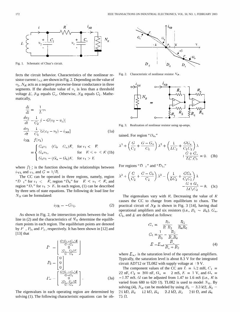
Fig. 1 shows the schematic of the CC in which the value ofthe voltage-controlled nonlinear resistor significantly af-
0278-0046/03$17.00 © 2003 IEEE
172 IEEE TRANSACTIONS ON INDUSTRIAL ELECTRONICS, VOL. 50, NO. 1, FEBRUARY 2003
Fig. 1. Schematic of Chua’s circuit.
fects the circuit behavior. Characteristics of the nonlinear re-sistor current are shown in Fig. 2. Depending on the value of
, acts as a negative piecewise-linear conductance in threesegments. If the absolute value of is less than a thresholdvoltage , equals . Otherwise, equals . Mathe-matically,
(1a)
for
for
for
(1b)
where is the function showing the relationships betweenand , and .
The CC can be operated in three regions, namely, region“ ” for , region “ ” for , andregion “ ” for . In each region, (1) can be describedby three sets of state equations. The following dc load line for
can be formulated:
(2)
As shown in Fig. 2, the intersection points between the loadline in (2) and the characteristics of determine the equilib-rium points in each region. The equilibrium points are denotedby , , and , respectively. It has been shown in [12] and[13] that
(3a)
The eigenvalues in each operating region are determined bysolving (1). The following characteristic equations can be ob-
Fig. 2. Characteristic of nonlinear resistorN .
Fig. 3. Realization of nonlinear resistor using op-amps.
tained. For region “ ,”
(3b)
For regions “ ” and “ ,”
(3c)
The eigenvalues vary with . Decreasing the value ofcauses the CC to change from equilibrium to chaos. Thepractical circuit of is shown in Fig. 3 [14], having dualoperational amplifiers and six resistors (i.e., ). ,
, and are defined as follows:
(4)
where is the saturation level of the operational amplifiers.Typically, the saturation level is about 8.3 V for the integratedcircuit AD712 or TL082 with supply voltage at9 V.
The component values of the CC are mH,nF, nF, mS, V, and
mS. can be adjusted from 1.47 to 1.6 mS (i.e.,isvaried from 680 to 620 ). TL082 is used to model . Bysolving (4), can be modeled by using k ,
k , k , k , , and.
TSEet al.: SWITCHING CONVERTERS WITH CHAOTIC CARRIER-FREQUENCY MODULATION 173
(a) (b)
(c) (d)
(e) (f)
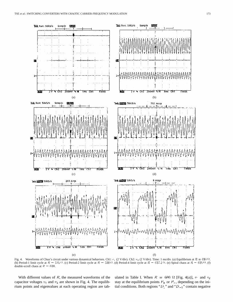
Fig. 4. Waveforms of Chua’s circuit under various dynamical behaviors. Ch1:v (2 V/div). Ch2:v (2 V/div). Time: 1 ms/div. (a) Equilibrium atR = 680.(b) Period-1 limit cycle atR = 645. (c) Period-2 limit cycle atR = 638. (d) Period-4 limit cycle atR = 637:5. (e) Spiral chaos atR = 635. (f)double-scroll chaos atR = 620.
With different values of , the measured waveforms of thecapacitor voltages and are shown in Fig. 4. The equilib-rium points and eigenvalues at each operating region are tab-
ulated in Table I. When [Fig. 4(a)], andstay at the equilibrium points or , depending on the ini-tial conditions. Both regions “ ” and “ ” contain negative

174 IEEE TRANSACTIONS ON INDUSTRIAL ELECTRONICS, VOL. 50, NO. 1, FEBRUARY 2003
TABLE IEQUILIBRIUM POINTS AND EIGENVALUES FORTHREEOPERATING REGIONS
eigenvalues. When is changed to 645 [Fig. 4(b)], the realpart of the complex conjugates of the eigenvalues becomes pos-itive. Period-1 limit cycle (also called Hopf bifurcation) occurs.Also, depending on the initial conditions, the states can oscil-late around the equilibrium points at or , and exhibit asinusoidal-like waveform at fixed frequency of 3.5 kHz, whichcan be calculated from the imaginary part of the complex con-jugates of the eigenvalues in region “” or “ .” Whenis 638 and 637.5 [Fig. 4(c) and (d)], period-2 and period-4limit cycles are observed, respectively. Further reducingleadsto spiral chaos [Fig. 4(e)] and double-scroll chaos [Fig. 4(f)]. At
[Fig. 4(e)], the circuit states fluctuate around theequilibrium points but no fixed limit cycle occurs. The state tra-jectories form a spiral attractor. At [Fig. 4(f)], thestates fluctuate around and from time to time.
III. PSD OF THE CC OUTPUT AND PRACTICAL
IMPLEMENTATION IN FMSS
Fig.5shows the threebasicdc/dcconverters,namely, thebuck,boost, and buck–boost converters. The common method of con-trolling the output voltage is to adjust the duty cycle and/orthe switching frequency (or the switching period) of the mainswitch . Practically, a PWM modulator [15], which consists ofa sawtooth generator of constant frequency together with a com-parator, can be used to determine the switching action of.
Incorporation of chaotic behavior into the PWM scheme isdepicted in Fig. 6. in Fig. 1 can be used to dither the switchingfrequency of a converter. It is sampled and is superimposedon a dc value, which determines the nominal switching fre-quency of the converter. The composite signal is connected to avoltage-controlled sawtooth generator. Thus, the switching pe-riod of the generated sawtooth waveform varies in accordancewith the magnitude of the composite signal. The output of theerror amplifier is compared to the generated sawtooth signal,and thus generating a PWM signal for the main switch in the
(a)
(b)
(c)
Fig. 5. Three basic types of dc/dc converters. (a) Buck converter. (b) Boostconverter. (c) Buck–boost converter.
Fig. 6. Incorporation of chaotic behavior into the PWM scheme.
converter. It is important to note that the duty cycle remains un-changed even if the switching frequency is varying. Based onthe fundamental considerations of sampled-data systems, a sam-pling rate of ten or more times the closed-loop bandwidth of thesystem is chosen for recovering the control signal. In analogy,the switching frequency of the power stage is selected to behigher than the oscillation frequency of the CC output in thisapplication. In performing the experiment, the switching fre-quency was chosen to be 45 kHz while the oscillation frequencyof the CC was 3.6 kHz. The ratio is 12.5.
Fig. 7(a) and (b) shows the experimental amplitude distribu-tions of the sampled (i.e., ) in Fig. 6 when the CC is inperiod-1 limit cycle and chaos, respectively. The figures are ex-tracted from a Tektronix TDS 784C oscilloscope. The shadedarea on the left-hand side, which is displayed together with the

TSEet al.: SWITCHING CONVERTERS WITH CHAOTIC CARRIER-FREQUENCY MODULATION 175
(a)
(b)
Fig. 7. Amplitude distribution under different operating modes. (a) Period-1limit cycle. (b) Chaotic operation.
time waveform, is the histogram of the vertical values of. Thehorizontal span at a vertical position represents the number ofoccurrence of that particular value of. The value of is con-centrated on the positive and negative peak values [16] in theperiod-1 limit cycle and it has a nearly triangular distribution inchaotic operation.
Fig. 8(a) and (b) shows the power spectral densities (PSDs)of the waveforms in Fig. 7. The PSD contains discrete har-monics in period-1 limit cycle [Fig. 8(a)] and becomes contin-uous spectra in chaotic operation [Fig. 8(b)]. In other words, thePWM signal generated by the circuit shown in Fig. 6, can exhibitdifferent spectral distributions under different operating modes.In particular, if the signal is chaotic, the harmonic power can bespread over the spectrum and the peak level of the PSD becomesless than that of the classical PWM scheme. Discrete harmonicscan, therefore, be significantly reduced. The harmonic power isspread continuously over the spectrum. The nonrepetitive na-ture of the signal in Fig. 7(b) and the continuous spectrum inFig. 8(b) can be approximated by using the RCFMS with fixedduty cycle switching scheme.
IV. M ATHEMATICAL ANALYSIS UNDER CCFMS
Based on the analysis for RCFMS, a mathematical functionshown in Fig. 9 is used to model the probability density function
(a)
(b)
Fig. 8. PSD ofv under different operating modes. (a) Period-1 limit cycle.(b) Chaotic operation.
Fig. 9. Probability density function of the switching period.
Fig. 10. Waveform of a PWM pulse train with chaotic switching.
of the period of the th switching cycle in Fig. 7(b). variesbetween a minimum possible value and maximum possiblevalue . Fig. 10 shows the waveform of a PWM pulse train
. has two discrete levels, namely, and .

176 IEEE TRANSACTIONS ON INDUSTRIAL ELECTRONICS, VOL. 50, NO. 1, FEBRUARY 2003
For studying the effectiveness of the stochastic variable (i.e.,the switching period ), an amplitude variation level is de-fined as
(5)
Thus, the triangular probability density function in Fig. 9 is de-fined for a given , since the area under the triangle is unity.
The PSD of the PWM pulse train in Fig. 10 can be shown tobe equal to
(6)
where is the complex conjugate of . is proba-bility density function of in Fig. 9. Detailed proof of (6) is shownin the Appendix. All expected terms in (6) can be expressed asfollows:
(7)
(8)
where and . Thus,
(9)
(10)
(11)
(12)
For the input current of the buck converter, equalsOutput Power and equals zero ( is the nominalduty cycle). Equations (9)–(12) can be rewritten as follows:
(13)
and
(14)
(15)
(16)
As depicted in Fig. 11(a), a dc/dc converter can be consid-ered as a low-pass filter fed by different types of input sources,which are dependent on the circuit configuration. With the aidof Table II, the transformed circuits are shown in Fig. 11.
Denote as the transfer function of the filter. The PSDof the noise output of the converter can be shown tobe [17]
(17)
Noise power is calculated by integrating over thespectrum. Hence, the root-mean-square value of the noise ripple
in the converter output is
(18)

TSEet al.: SWITCHING CONVERTERS WITH CHAOTIC CARRIER-FREQUENCY MODULATION 177
TABLE IITRANSFERCHARACTERISTICS OFVARIOUS DC/DC CONVERTERS
(a)
(b)
(c)
(d)
Fig. 11. Equivalent circuit of dc/dc converters. (a) Basic configuration. (b)Buck converter. (c) Boost converter. (d) Buck–boost converter.
Due to the rapid roll-off characteristics in at high-fre-quency range, can be approximated by
(19)
Only the continuous component and the dc component existover the spectrum. Thus,
(20)
where is the number of frequency points over the range of.
V. EVALUATION OF THE PSD WITH CCFMS
The three basic converters in Fig. 5 are studied. The compo-nent values are H, , F,
, and . is 22 V. The nominal switchingfrequency is 45 kHz and duty cycle is 0.55. The PSDs ofthe input currents of the three converters are obtained by usingPSIM 4.0 [18]. The simulated data are processed by Matlab[19], in order to calculate the corresponding PSDs. The resultsare shown in Fig. 12. Instead of containing discrete harmonics,the PSD’s of the three converters’ input currents are all in con-tinuous spectra. Fig. 13 shows the theoretical prediction of theinput current PSD of the buck converter using (6) with
. Figs. 12(a) and 13 are in close agreement at the high-frequency range. However, discrepancies occur in the low-fre-quency range, which will be explained in the following.
Fig. 14 shows the variations of the PSD of the diode voltageof the buck converter with respect to the changes in.
is changed from 0 to 0.4. When is zero, the PSD is the sameas the PSD of the SPWMS. Asincreases, the harmonic spec-trum is gradually spread over. No significant improvements inspreading high-frequency harmonics are observed whenislarger than 0.35. Fig. 15 shows the simulated low-frequencycharacteristic of when is 0.35. The prediction will be ver-ified with the experimental one in Section VI.
VI. EXPERIMENTAL VERIFICATIONS
A buck converter was tested and the PSDs were recorded bythe HP 8941 spectrum analyzer with resolution bandwidth of300 Hz. A current probe with sensitivity of 20 mV/A is used tomeasure the converter input current. Thus, the measured PSD

178 IEEE TRANSACTIONS ON INDUSTRIAL ELECTRONICS, VOL. 50, NO. 1, FEBRUARY 2003
(a)
(b)
(c)
Fig. 12. PSD of input current of the three power converters under chaoticswitching. (a) Buck converter. (b) Boost converter. (c) Buck–boost converter.
equals the sum of the actual PSDand the conversionfactor of the current probe. That is,
dB (21)
Fig. 16 shows the measured PSD when the CC is in equi-librium, period-1 limit cycle, and chaos. Under chaotic oper-ation, the PSD is in close agreement with the predictions inFigs. 12(a) and 13. Discrete harmonics are observed at equilib-rium [Fig. 16(a)] and period-1 limit cycle [Fig. 16(b)]. When the
Fig. 13. Theoretical prediction of the input current PSD using (6) when< =
0:35.
Fig. 14. PSD of the diode voltage with respect to the changes in<.
Fig. 15. Simulated low-frequency characteristic of the diode voltage withRCFMS and< = 0:35.
switching frequency becomes chaotic [Fig. 16(c)], the power ofthe switching harmonics is well spread over.
Fig. 17 shows the low-frequency PSD of under theCCFMS and the RCFMS. The modulating signal in theRCFMS is shown in Fig. 18. A 10:1 probe is used to pick up
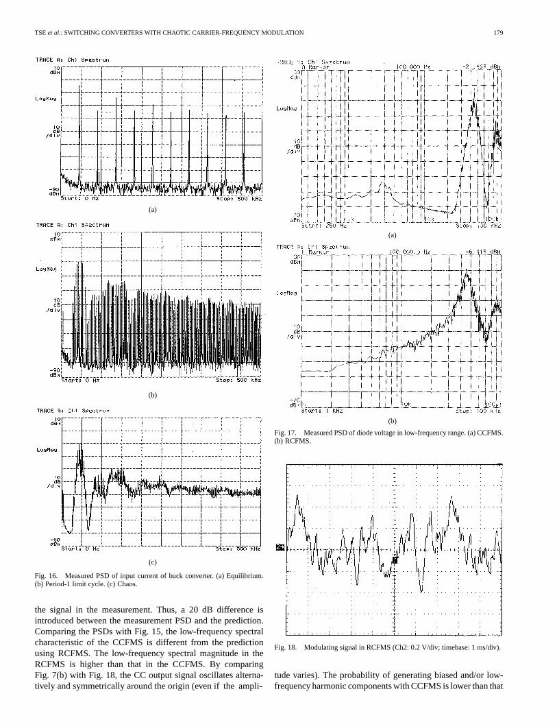
TSEet al.: SWITCHING CONVERTERS WITH CHAOTIC CARRIER-FREQUENCY MODULATION 179
(a)
(b)
(c)
Fig. 16. Measured PSD of input current of buck converter. (a) Equilibrium.(b) Period-1 limit cycle. (c) Chaos.
the signal in the measurement. Thus, a 20 dB difference isintroduced between the measurement PSD and the prediction.Comparing the PSDs with Fig. 15, the low-frequency spectralcharacteristic of the CCFMS is different from the predictionusing RCFMS. The low-frequency spectral magnitude in theRCFMS is higher than that in the CCFMS. By comparingFig. 7(b) with Fig. 18, the CC output signal oscillates alterna-tively and symmetrically around the origin (even if the ampli-
(a)
(b)
Fig. 17. Measured PSD of diode voltage in low-frequency range. (a) CCFMS.(b) RCFMS.
Fig. 18. Modulating signal in RCFMS (Ch2: 0.2 V/div; timebase: 1 ms/div).
tude varies). The probability of generating biased and/or low-frequency harmonic components with CCFMS is lower than that

180 IEEE TRANSACTIONS ON INDUSTRIAL ELECTRONICS, VOL. 50, NO. 1, FEBRUARY 2003
of the RCFMS. Hence, even if the CCFMS and RCFMS are sto-chastic in nature and exhibit the same probability density func-tion, their spectral behaviors are slightly different because thetime-domain variation cannot be obtained from the probabilitydensity function. Nevertheless, CCFMS has the advantages thatit does not introduce significant low-frequency harmonics andthat it improves high-frequency characteristics in the SPWMS.
VII. CONCLUSIONS
A CCFMS has been analyzed and evaluated. The CC has beenincorporated into the switching control of the power converters.The input current and output voltage power spectral densitiesunder different operating regions have been studied theoreti-cally and experimentally. By controlling the dynamics of theCC, it has been shown that CCFMS hybridizes the features ofPCFMS and RCFMS. Experimental results have confirmed thatCCFMS is an alternative way for reducing the amplitudes ofswitching harmonics. Most importantly, the CCFMS introducesless low-frequency harmonics at the output than the RCFMS.Apart from studying the effect of chaotic frequency modulationon switching converters, this paper also provides the method-ology of analysis. Readers can use other kinds of chaotic gen-erators with similar analysis method. Further research will bededicated to studying the sensitivities of the PSD to the circuitparameters.
APPENDIX
A. Proof of (6)
Considering the generic switching cyclein Fig. 10, theswitching waveform , can be expressed as
forforelsewhere
(A.1)
where is a randomized switching period. A general expres-sion for is
(A.2)
The autocorrelation of is defined as
(A.3)
where is the expected value of the quantity inside thebracket. is the observation interval, containing expectedvalue of . That is,
(A.4)
By substituting (A.2) and (A.4) into (A.3),
(A.5)
If and denote the Fourier transform of and, respectively, and denotes the time integral in (A.5),
(A.6)
Referring to [3],
(A.7)
Equation (A.6) can be expressed as
(A.8)
Hence, the autocorrelation ofcan be expressed as
(A.9)
Based on the Wiener–Khinchin theorem [20], the PSD of asignal is the Fourier transform of its autocorrelationfunction . Conversely, the autocorrelation can be given bythe inverse Fourier transform of the PSD. That is,
(A.10)
and
(A.11)
With this relationship, the PSD of over the range of posi-tive frequency is easily observed from (A.9), interms of the randomness level of, i.e.,
(A.12)
Consider denoting the double summation of the expectedterm in (A.12),
(A.13)

TSEet al.: SWITCHING CONVERTERS WITH CHAOTIC CARRIER-FREQUENCY MODULATION 181
where
(A.14)
is dependent on if
(A.15)
and is dependent on if
(A.16)
Hence, (A.14) can be shown to be
(A.17)
where
(A.18)
Consider
(A.19)
and
forfor .
(A.20)
Thus, (A.18) becomes a real number as
Re
(A.21)
Since , (A.21) is simplified as
(A.22)
By substituting (A.22) into (A.17),
(A.23)
Finally, (A.13) becomes
(A.24)
REFERENCES
[1] S. Legowski and M. Trzynadlowski, “Power-Mosfet, hypersonic inverterwith high-quality output current,” inIEEE APEC’90, 1990, pp. 3–7.
[2] T. G. Habeter and D. M. Divan, “Acoustic noise reduction in sinusoidalPWM drives using a randomly modulated carrier,”IEEE Trans. PowerElectron., vol. 6, pp. 356–363, May 1991.
[3] R. L. Kirlin, S. Kwok, S. Legowski, and A. M. Trzynadlowski, “Powerspectra of a PWM inverter with randomized pulse position,”IEEE Trans.Power Electron., vol. 9, pp. 463–472, Sept. 1994.
[4] F. Lin and D. Y. Chen, “Reduction of power supply EMI emission byswitching frequency modulation,”IEEE Trans. Power Electron., vol. 9,pp. 132–137, Jan. 1994.
[5] D. A. Stone and B. Chambers, “Effect of spread-spectrum modulation ofswitched mode power converter PWM carrier frequencies on conductedEMI,” Electron. Lett., vol. 31, no. 10, pp. 769–770, 1995.
[6] K. K. Tse, H. Chung, S. Y. R. Hui, and H. C. So, “A comparative inves-tiation on the use of random modulation schemes for dc/dc converters,”IEEE Trans. Ind. Electron., vol. 47, pp. 253–263, Apr. 2000.
[7] , “Spectral characteristics of randomly switched PWM dc/dc con-verters operating in discontinuous conduction mode,”IEEE Trans. Ind.Electron., vol. 47, pp. 759–769, Aug. 2000.
[8] , “Analysis and Spectral characteristics of a spread-spectrum tech-nique for conducted EMI suppression,”IEEE Trans. Power Electron.,vol. 15, pp. 399–410, Mar. 2000.
[9] S. Y. R. Hui, I. Oppermann, and S. Sathiakumar, “Microprocessor-basedrandom PWM schemes for DC-AC power conversion,”IEEE Trans.Power Electron., vol. 12, pp. 253–260, Mar. 1997.
[10] F. Ueno, I. Oota, and I. Harada, “A low-noise control circuit usingChua’s circuit for a switching regulator,” inProc. Eur. Conf. CircuitTheory and Design, 1995, pp. 1149–1152.
[11] J. H. B. Deane and D. C. Hamill, “Improvement of power supply EMCby Chaos,”Electron. Lett., vol. 32, no. 12, p. 1045, 1996.
[12] M. P. Kennedy, “Three steps to chaos—Part I,”IEEE Trans. CircuitsSysts. I, vol. 40, pp. 640–656, Oct. 1993.
[13] M. P. Kennedy, “Three steps to chaos—Part II,”IEEE Trans. CircuitsSysts. I, vol. 40, pp. 657–674, Oct. 1993.
[14] R. N. Madan,Chua’s Circuit: A Paradigm of Chaos, Singapore: WorldScientific, 1993.
[15] N. Mohan, T. M. Undeland, and W. P. Robbins,Power Elec-tronics—Converters, Applications, and Design. New York: Wiley,1995.
[16] J. J. O’Reilly, Telecommunication Principles. London, U.K.:Chapman & Hall, 1991.
[17] A. Papoulis, Probability Random Variables, and Stochastic Pro-cesses. New York: McGraw-Hill, 1991.

182 IEEE TRANSACTIONS ON INDUSTRIAL ELECTRONICS, VOL. 50, NO. 1, FEBRUARY 2003
[18] PSIM User Manual, Powersim Technologies Inc., Surrey, BC, Canada,1998.
[19] T. P. Kraus, L. Shure, and J. N. Little,Signal Processing Toolbox for UseWith Matlab. Natick, MA: The MathWorks Inc., 1994.
[20] D. Middleton, An Introduction to Statistical CommunicationTheory. New York: McGraw-Hill, 1988.
K. K. Tse (M’00) received the B.Eng. (Hons.) degreein electrical engineering from The Hong Kong Poly-technic University, Hong Kong, and the Ph.D. degreefrom City University of Hong Kong, Hong Kong, in1995 and 2000, respectively.
He served as a Lecturer at the Hong Kong Instituteof Vocational Education (Tsing Yi) (formerly Tech-nical College) in 1998. From 1999 to 2001, he wasa Research Fellow in the Electronic Engineering De-partment, City University of Hong Kong. Since June2001, he has been with Johnson Electric, Hong Kong,
where he is currently a Technical Specialist in the R&D area. He has authoredmore than 20 published technical papers in the areas of his research interests,which include new numerical model methods and computer-aided simulationtechniques, EMI reduction using random switching schemes for dc–dc con-verters, and new maximum power tracking techniques for PV cells.
Dr. Tse received the First Prize in 1998 in the IEEE Postgraduate StudentPaper Contest, Hong Kong Section, and the Third Prize in the 1999 Region 10IEEE Postgraduate Student Paper Contest. He was a recipient of The CroucherFoundation Fellowship in 2000. In December 2000, he received the SilverAward in the Young Inventor Competition, jointly organized by the Far EasternEconomic Review and Hewlett Packard Company.
Raymond Wai-Man Ngwas born in Hong Kong. Hereceived the B.Eng. (Hons.) degree in electronic engi-neering in 1988 from City University of Hong Kong,Hong Kong, where he is currently working toward theMaster of Philosophy degree.
In 1998, he joined ASTEC Custom Power (HK)Ltd., Kong Kong, as a Design Engineer. Since 2000,he has been the Application Engineer on EricssonPower Module Team. His research interests are EMIand dc/dc conversion.
Henry Shu-Hung Chung (S’92–M’95) received theB.Eng. (with first class honors) degree in electricalengineering and the Ph.D. degree from The HongKong Polytechnic University, Hong Kong, in 1991and 1994, respectively.
Since 1995, he has been with City University ofHong Kong, Hong Kong, where he is currently anAssociate Professor in the Department of ElectronicEngineering. His research interests include time- andfrequency-domain analysis of power electronic cir-cuits, switched-capacitor-based converters, random-
switching techniques, digital audio amplifiers, soft-switching converters, andelectronic ballast design. He has authored four research book chapters and morethan 130 technical papers, including 70 refereed journal papers in the current re-search area, and is the holder of two U.S. patents.
Dr. Chung is currently the IEEE Student Branch Counselor at City Universityof Hong Kong and was Track Chair of the Technical Committee on Power Elec-tronics Circuits and Power Systems of the IEEE Circuits and Systems Society in1997–1998. He is presently an Associate Editor of the IEEE TRANSACTIONS ON
CIRCUITS AND SYSTEMS—I: FUNDAMENTAL THEORY AND APPLICATIONS andthe Guest Editor of the Special Issue on Analysis, Design and Applications ofSwitching Circuits and Systems. He was the recipient of the China Light andPower Prize and was awarded the Scholarship and Fellowship of the Sir Ed-ward Youde Memorial Fund in 1991 and 1993, respectively. He was awardedthe Grand Applied Research Excellence Award in 2001 from City University ofHong Kong.
S. Y. Ron Hui (SM’94–F’03) was born in HongKong in 1961. He received the B.Sc. (Hons.)degree in 1984 from the University of Birmingham,Birmingham, U.K., and the D.I.C. and Ph.D. degreein 1987 from Imperial College of Science andTechnology, University of London, London, U.K.
He was a Lecturer in power electronics at theUniversity of Nottingham, Nottingham, U.K., in1987–1990. In 1990, he took up a lectureship at theUniversity of Technology, Sydney, Australia, wherehe became a Senior Lecturer in 1991. He joined
the University of Sydney in 1993 and was promoted to Reader of ElectricalEngineering and Director of the Power Electronics and Drives Research Groupin 1996. He is currently a Chair Professor of Electronic Engineering and anAssociate Dean of the Faculty of Science and Engineering at City University ofHong Kong, Hong Kong. He has authored more than 150 published technicalpapers, including more than 80 refereed journal publications. His researchinterests include all aspects of power electronics.
Prof. Hui received the Teaching Excellence Award in 1999 and the Grand Ap-plied Research Excellence Award in 2001 from City University of Hong Kong.He has been appointed an Honorary Professor by the University of Sydney since2000.