Embed Size (px)
Citation preview

An All-Hex Meshing Strategy for Bifurcation
Geometries in Vascular Flow Simulation
Chaman Singh Verma1, Paul F. Fischer1, Seung E. Lee2, and F. Loth3
1 Mathematics and Computer Science Division, Argonne National Laboratory,Argonne, IL 60439
2 Dept. of Mechanical Engineering, Massachusetts Institute of Technology,Cambridge, MA 02319
3 Dept. of Mechanical Engineering, University of Illinois, Chicago, IL 60607
Summary. We develop an automated all-hex meshing strategy for bifurcation ge-ometries arising in subject-specific computational hemodynamics modeling. The keycomponents of our approach are the use of a natural coordinate system, derived fromsolutions to Laplace’s equation, that follows the tubular vessels (arteries, veins, orgrafts) and the use of a tripartitioned-based mesh topology that leads to balancedhigh-quality meshes in each of the branches. The method is designed for situationswhere the required number of hexahedral elements is relatively small (∼ 1000–4000), as is the case when spectral elements are employed in simulations at transi-tional Reynolds numbers or when finite elements are employed in viscous dominatedregimes.
1 Introduction
We develop an automated all-hex meshing strategy for bifurcation geome-tries arising in subject-specific computational hemodynamics modeling. Ourstrategy is designed for the spectral element method (SEM) but works equallywell for hex-based finite volume or finite element methods. Similar to the finiteelement method, the SEM is a high-order weighted residual technique featur-ing isoparametric hexahedral (hex) elements that are globally assembled intoan unstructured mesh. A distinguishing feature of spectral element meshesis that they generally require orders of magnitude fewer elements than theirfinite-element counterparts because each spectral element typically contains100s to 1000s of gridpoints. This reduction often poses significant challengesfor conventional approaches to automated hex-mesh generation because thereare relatively few interior elements over which to apply smoothing in order toabsorb topological corrections that arise from, say, merging advancing fronts.It is of interest, therefore, to construct meshes having intrinsically compati-ble geometries and topologies. For most hemodynamic flow domains, whichprimarily comprise tubes and bifurcations, there are decompositions that are

2 Chaman Singh Verma, Paul F. Fischer, Seung E. Lee, and F. Loth
readily tessellated by hexahedra using sweeping methods [8, 9]. The chal-lenge, however, is to develop robust, fast, and fully automated schemes forpatient-specific geometries, which often feature tortuous passages with sharpcurvature and (in the presence of stenoses) rapid variation in diameter. Anadditional complication, separate from the question of meshing is that thegeometry is not well defined but must generally be inferred from slice-basedmedical images that are often highly pixelated with respect to the vessel di-ameter. Certainly, the geometry definition, which involves image registrationand segmentation, is an integral part of the automated procedure, but we donot discuss it further here. We also note that, while the mesh generation tech-niques proposed here are designed specifically for vascular flow geometries,they could be adapted to work equally well in other internal flow configura-tions involving bifurcating channels.
2 Background and Flow Modeling
During the past two decades, the role of hemodynamics, or fluid mechanics ofblood flow, has been implicated in the development of arterial disease and inthe regulation of cellular biology in both normal and diseased arteries [5, 6].Vascular disease, including atherosclerosis, aneurysms, and plaque disruptionis one of the leading causes of death in the United States. A number of meth-ods are being used to investigate the hemodynamic forces in the vascularsystem, with computational fluid dynamics (CFD) becoming the most preva-lent because of its ability to provide more detailed flow information than eitherin vivo or in vitro experiments. Although significant insight has been gainedfrom CFD simulations in idealized vascular geometries, geometry clearly hasa dominant influence on the local hemodynamics and there is a consequentneed for subject-specific vascular flow modeling [7].
While the natural flow state in the vasculature is laminar, it is possibleto have a transition to a weakly turbulent state in the presence of stenoses(blockages) or subsequent to surgical procedures such as arteriovenous graftimplantation [12]. The transition to turbulence induces a sudden change inthe range of spatial and temporal scales in the solution, resulting in a needfor two to three orders of magnitude increase in computational resources forthe same physical-time simulation. The flow physics in the turbulent case isdominated by convection of momentum with relatively little diffusion. Thenon-dimensional ratio of these two processes is denoted as the Reynolds num-ber, which is typically Re ∼ 350 in healthy vessels but can reach as high asRe=1000–3000 in the transitional cases. For simulations in the high Reynoldsnumber regime where physical dissipation is small, it is beneficial to use high-order numerical discretizations that have minimal numerical dispersion anddissipation per grid point [2].
Our numerical approach is based on the SEM, which is a high-orderweighted residual technique that combines the geometric flexibility of the

All-Hex Meshing for Bifurcation Geometries 3
finite element method (FEM) with the rapid convergence and tensor-productefficiencies of global spectral methods. In the SEM, the domain is decomposedinto E curvilinear hexahedral elements, and the solution within each elementis represented as an Nth-order tensor-product nodal-based (Lagrange) poly-nomial. For three-dimensional problems, there are approximately EN3 grid-points in the entire domain.
We remark that high-order methods do not circumvent the need to resolveflow structures such as boundary layers and vortices. Both low- and high-order methods must capture the predominant structures. In the FEM therequisite resolution is attained by varying E, whereas in the SEM the resolu-tion is attained through a combined variation of E and N , with N=8–12 beingtypical. For the same resolution (i.e., number of gridpoints) the number of el-ements for an SEM discretization would be two to three orders of magnitudesmaller than its FEM counterpart. For example, typical SEM discretizationsof a bifurcation geometry involve 1000–4000 elements, whereas typical FEMdiscretizations involve > 105 elements. Because there are so few elements, itis critical that the SEM mesh topology and geometry be relatively free ofthe point and line dislocations that can result when two or more mesh frontsconverge when using advancing front or similar generalized meshing meth-ods. For the FEM, achieving this topology is less of a problem because meshsmoothing can be used to effectively spread the geometric penalty arising fromsuch topological defects over a large number of elements. For the SEM, meshsmoothing is also important but is more constrained by the (topological) prox-imity of the boundaries. Fortunately, for the class of geometries that we areconsidering here, which comprises blood vessels and bifurcations, high-qualityall-hex decompositions exist, and we are able to exploit this domain-specificinformation to develop a robust and fully automated meshing procedure thatworks equally well for the SEM and, through mesh refinement, for the FEM.
3 Vessel Surface Definition
Currently, we are using noncompact radial basis functions (RBFs) to repre-sent the vessel surface [1]. We opted for noncompact RBF for the followingreasons: (i) the initial point cloud was noise-free, (ii) the number of points wasreasonable to be handled by ordinary Linux machines, and (iii) noncompactthin-plate RBFs provide smooth surfaces. The RBF-based implicit surfaceconstruction requires a set of known interpolating points that we constructas follows. Given surface points xj , j = 1, . . . , n, we identify a set of externalpoints, yk, k = 1, . . . , m, near the surface using an oct-tree algorithm thatmarches inward with successively smaller boxes from the edges of a boundingbox. With the known oct-tree topology, we identify as external points the cen-ters of small empty boxes adjacent to those containing surface points. Fromthese, we define a signed distance and construct an interpolating RBF, φ(x),
4 Chaman Singh Verma, Paul F. Fischer, Seung E. Lee, and F. Loth
that vanishes at all xj and matches the signed distance at all yk. The surfacewhere φ(x) ≡ 0 defines the vessel wall.
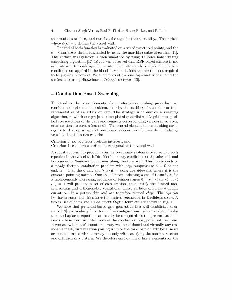
The radial basis function is evaluated on a set of structured points, and theφ = 0 surface is then triangulated by using the marching cubes algorithm [11].This surface triangulation is then smoothed by using Taubin’s nonshrinkingsmoothing algorithm [17, 18]. It was observed that RBF-based surface is notaccurate near the end-caps. These sites are locations where artificial boundaryconditions are applied in the blood-flow simulations and are thus not requiredto be physically correct. We therefore cut the end-caps and triangulated thesurface cuts using Shewchuck’s Triangle software [15].
4 Conduction-Based Sweeping
To introduce the basic elements of our bifurcation meshing procedure, weconsider a simpler model problem, namely, the meshing of a curvilinear tuberepresentative of an artery or vein. The strategy is to employ a sweepingalgorithm, in which one projects a templated quadrilateral O-grid onto speci-fied cross-sections of the tube and connects corresponding vertices in adjacentcross-sections to form a hex mesh. The central element to our meshing strat-egy is to develop a natural coordinate system that follows the undulatingvessel and satisfies two criteria:
Criterion 1: no two cross-sections intersect, andCriterion 2: each cross-section is orthogonal to the vessel wall.
A robust approach to producing such a coordinate system is to solve Laplace’sequation in the vessel with Dirichlet boundary conditions at the tube ends andhomogeneous Neumann conditions along the tube wall. This corresponds toa steady thermal conduction problem with, say, temperature α = 0 at oneend, α = 1 at the other, and ∇α · n = along the sidewalls, where n is theoutward pointing normal. Once α is known, selecting a set of isosurfaces fora monotonically increasing sequence of temperatures 0 = α
1< α
2< . . . <
αm = 1 will produce a set of cross-sections that satisfy the desired non-intersecting and orthogonality conditions. These surfaces often have doublecurvature like a potato chip and are therefore termed chips. The αis canbe chosen such that chips have the desired separation in Euclidean space. Atypical set of chips and a 12-element O-grid template are shown in Fig. 1.
We note that potential-based grid generation is a well-established tech-nique [19], particularly for external flow configurations, where analytical solu-tions to Laplace’s equation can readily be computed. In the present case, oneneeds a base mesh in order to solve the conduction (i.e., potential) problem.Fortunately, Laplace’s equation is very well conditioned and virtually any rea-sonable mesh/discretization pairing is up to the task, particularly because weare not concerned with accuracy but only with satisfying the non-intersectionand orthogonality criteria. We therefore employ linear finite elements for the

All-Hex Meshing for Bifurcation Geometries 5
Fig. 1. (a) Isosurfaces of α in an isolated vessel. (b) Level-0 O-grid template.
conduction problem. Starting with a surface triangulation, we build a tetra-hedral mesh using the advancing front algorithm [13]. We then construct thefinite element Laplacian, apply the requisite boundary conditions, and solvethe sparse linear system by using conjugate gradient iteration. The surface tri-angulation is smoothed by using Taubin’s non-shrinking algorithm [17]. Withα known, the O-grid is swept through the domain and projected onto chipswhere α(x) = αi. The O-grid template is aligned by minimizing the Euclidiandistance between the “S” points (Fig. 1b) when the template is mapped ontoadjacent chips. The remaining edge points are distributed according to ar-clength. The interior point distribution is parameterized by using local polarcoordinates, with arclength acting as the azimuthal variable, and the radialcoordinate normalized by the distance from the chip centroid to the perimeter.
5 Bifurcation Geometries
Our bifurcation meshing strategy is based on a tripartition of the domaininto three tubes, each of which is meshed using a variant of the sweepingalgorithm described in the preceding section. This approach yields minimalelemental deformation and balanced resolution in each branch. (The initialmesh can be further improved through mesh smoothing techniques [4, 14] andthe local resolution enhanced through p- or h-type refinement, e.g., [3].) Ouroriginal implementation of the tripartition algorithm was based on a seriesof cross-sections that were orthogonal to the plane containing the bifurcation[8, 9]. Such an approach, however, is not robust because it does not guaranteeCriteria 1 and 2. We therefore extend this tripartition approach to incorporatethe natural coordinate system introduced in Section 4.
We demonstrate that, in addition to satisfying Criteria 1 and 2, the Lapla-cian isosurfaces provide a robust and natural tripartition of the bifurcationgeometry. We begin by noting that any two of the three branches may beswept by solving Laplace’s equation with α = 0 on one end-cap, α = 1 onanother, and ∇α · n = 0 elsewhere. The third branch can be swept by cycli-cally permuting these boundary conditions and solving a second conductionproblem. For symmetry and for completeness of the algorithm, we solve threeconduction problems in total, each having, in turn, one branch insulated while

6 Chaman Singh Verma, Paul F. Fischer, Seung E. Lee, and F. Loth
Table 1. Boundary Conditions for Bifurcation Conduction Problems
Problem ΓA ΓB ΓC
A: ∇2α = 0 0 = ∇α · n α = −αP α = 1 − αP
B: ∇2β = 0 β = 1 − βP 0 = ∇β · n β = −βP
C: ∇2γ = 0 γ = −γP γ = 1 − γP 0 = ∇γ · n
the other two have end-caps at different fixed values. Denoting the branchesas A, B, and C, with respective end-caps ΓA, ΓB, and ΓC , we solve conductionproblems for α, β, and γ satisfying the boundary conditions listed in Table 1.For each case, the Dirichlet values have been shifted by a constant (denotedwith subscript P ) so that the temperature at the center of the insulated end-cap is zero. The isosurfaces that (nominally) emanate from these centerpointsare referred to as the principal isosurfaces and, with the shift, correspond toα = 0, β = 0, and γ = 0.
The solutions for problems A–C are shown in Fig. 2 for a stenosed carotidartery bifurcation. A critical observation is that, to the level of truncationerror, the principal isosurfaces intersect in a unique curve, as illustrated in Fig.2d. (Uniqueness is further discussed in Appendices A and B.) These isosurfacesconsequently serve to tripartition the bifurcation, as required for our sweepingstrategy. In addition, they provide the bisecting “plane” that is required toorient the O-grid so that element boundaries are aligned with the cusp of eachbranch where it connects to the bifurcation. Thus six subdomains are definedby the principal isosurfaces: three branches, each having two halves. Denotingthe half of branch A that connects to B by AB, and so on for each half,we formally identify “half-chips” in subdomains AB and BA with isosurfacesof γ, those in BC and CB with isosurfaces of α, and those in CA and AC
with isosurfaces of β. As in Section 4, the chips defining adjacent slabs of hexelements are found by choosing α-isosurfaces (or β- or γ-) that yield a desiredEuclidean separation. (Hereon, unless otherwise indicated, we will restrict ourdiscussion to the problem of meshing the A-branch using isosurfaces of β andγ, with the understanding that the procedure for the other branches followsfrom symmetry.)
Refinements to the Approach
In infinite-precision arithmetic, the approach outlined above would suffice tomesh each branch in its entirety. A modest complication arises because theinsulated branch assumes a nearly uniform temperature as one moves awayfrom the bifurcation. Choosing αP so that the temperature in the insulatedbranch is close to zero and then recomputing α provides several significantdigits that would otherwise be lost and allows one to more precisely identifythe principal isosurface. Nevertheless, it is often difficult to identify the princi-pal isosurface more than two diameters away from the bifurcation, as is clear
All-Hex Meshing for Bifurcation Geometries 7
from Fig. 2. For two reasons, this situation is not a particular problem. First,we note that identifying the principal isosurface near the bifurcation is a veryrobust procedure. In exact arithmetic, all isosurfaces in the insulated branchcollapse exponentially fast to the principal isosurface as one approaches thebifurcation. Thus, starting from any point in the insulated branch, one canuse a marching tetrahedra algorithm and arrive at the principal isosurface.Second, away from the bifurcation, the principal isosurface merely serves as aguide to orient the O-grid and is not really needed. In the extremal regions,the O-grid can be mapped to either constant-β or constant-γ surfaces (for theA-branch), as the two families are indistinguishable. Thus, away from the bi-furcation, we simply pick one of two solutions (e.g., β or γ) and sweep towardthe extremity (A) following the procedure of Section 4.
Summary of Approach
With the basic concepts in hand, we summarize the steps of the procedure asfollows:
1. Starting from a noncompact RBF representation, construct a triangula-tion of the vessel surface.
2. Apply Taubin smoothing [17] to the surface triangulation.3. Use the advancing front algorithm to construct a preliminary tet mesh of
the domain volume.4. Using linear finite elements and conjugate gradient iteration, solve con-
duction problems for α, β, and γ (Table 1) with αP = βP = γP = 0.5. Set αP , βP , and γP to the negative of their respective insulated end-
cap centerpoint values and recompute α, β, and γ. (Iterate on Step 5, ifneeded.)
6. Identify the α = 0 principal isosurface with marching tets, and compute βand γ on this surface using the corresponding marching-tet interpolants.
7. Use marching triangles to identify the β = 0 and γ = 0 curves on theα = 0 principal isosurface. Average these curves to determine a commonrepresentation of the trisection curve. Identify the centerpoint (measuredin arc-length) of the trisection curve as the origin, O.
8. On the A-branch, march outward from O on the α = 0 surface a user-specified distance δ (typ., δ ≈ 1/4D, where D is the local vessel diameter).Denote the corresponding point as x
1.
9. Find the values β1
:= β(x1) and γ
1:= γ(x
1), and compute the correspond-
ing isosurfaces β(x) = β1
and γ(x) = γ1
with marching tets. Identify thefirst pair of half-chips with these isosurfaces.
10. Repeat Steps 8 and 9, generating points xi and corresponding isosurfacesuntil the dihedral angle of the β(x) = βi and γ(x) = γi chips at xi is< 10; then switch to the single-chip algorithm of Section 4 using eitherβ or γ as the coordinate.
11. Starting at O, project templated O-grids onto each chip or half-chip pair.

8 Chaman Singh Verma, Paul F. Fischer, Seung E. Lee, and F. Loth
Fig. 2. Isosurfaces for conduction problems A (a), B (b), and C (c) of Table 1; (d)intersection of principal isosurfaces.

All-Hex Meshing for Bifurcation Geometries 9
Fig. 3. Templated chips in a bifurcation geometry.
12. Smooth the quadrilateral surface mesh using Taubin smoothing, andproject the smoothed points onto the triangulated chip surface.
13. Repeat Steps 8–12 for branches B and C.14. Consistently order each contour on each chip with respect to the principal
isosurface half-chips.15. Construct the hexahedral volume mesh taking two adjacent chips at a
time.
Figure 3 shows the resulting templated chip set for the stenosed carotidbifurcation. A close up of the half-chips on the principal isosurfaces that trisectthe bifurcation are shown in Fig. 3b.
6 Results
We have successfully used an earlier variant of this approach, developed in[8, 9], to build several meshes for the study of transition in vascular flows[10, 12], This earlier mesh construction approach involved several disjointpieces of software and required significant user expertise to produce an ac-ceptable mesh. Typical turnaround time was on the order of five to ten days.Our current focus is on streamlining the entire procedure so that it is fullyautomated and requires minimal user input.
The current development code is in C++ and uses the Matrix TemplateLibrary [16] to solve the linear equations for the RBF and heat conductionproblems. The RBF coefficients were computed by using direct solves, whereasthe conduction problems were solved with Jacobi-preconditioned conjugategradient iteration. Table 2 shows preliminary performance results on a Linux2.4 GHz Pentium IV machine with a breakdown of the CPU time for each

10 Chaman Singh Verma, Paul F. Fischer, Seung E. Lee, and F. Loth
phase. We stress that this initial development code has not been optimized.The turnaround for the entire procedure has nonetheless been reduced to amatter of minutes, rather than days.
Table 2. Timing for Automated Generation of Carotid Bifurcation Mesh
Function Time ( in Seconds )
RBF coefficients evaluation 450RBF function evaluation on box 90.0Marching cube for φ = 0 evaluation 2Taubin surface fairing 1Trimming end sections 0.5Solution of three heat equations 400Principal chips construction 1Split chips construction 2Simple chips construction 4Mesh template 0.5Surface smoothing 0.001Volume mesh 0.0001
7 Future Directions
Our goal is to provide rapid generation of a quality hex mesh for vascular flowgeometries, starting with a sliced-based stack of medical images (i.e., CT-scanor MRI). presently, we are using commercial software to segment the images.This will be replaced by a snake algorithm that is incorporated as a modulein our mesh generation software. With all the modules in place, we will tackleoptimization of the algorithms described in the preceding sections. In particu-lar, we expect significant performance gains by using multigrid to preconditionthe thermal conduction problems. Similar performance gains are expected byimproving the RBF approach. For instance, we have been investigating theuse of multilevel RBFs that yield sparse coefficient matrices.
Acknowledgments
This work was supported by the National Institutes for Health, RO1 ResearchProject Grant (2RO1HL55296-04A2) and by the Mathematical, Information,and Computational Sciences Division subprogram of the Office of AdvancedScientific Computing Research, U.S. Department of Energy, under ContractW-31-109-Eng-38.

All-Hex Meshing for Bifurcation Geometries 11
AB
C
α
AB
C
β
z∗
AB
C
γ
Fig. 4. Two-dimensional model problem showing common intersection point z∗ forisopotentials α, β, and γ.
Appendix A
Our assertion that the three principal isosurfaces intersect in a unique one-dimensional curve is based primarily on observation of tens of two- and three-dimensional cases. Here, we demonstrate that uniqueness holds rigorouslyfor a special class of two-dimensional geometries, namely, for an arbitrarydistribution of source, sink, and isocontour points on a circle.
Consider the two-dimensional potential problem in the unit-disk having apoint source at B and a point sink of equal strength at C, as illustrated inFig. 4. The general solution in the complex z-plane is
u + iv = lnz − B
z − C+ c,
with u and v real-valued, i :=√−1, and c arbitrary. The isopotentials (cor-
responding to isothermal surfaces in Fig. 2) are given by isocontours of thereal part of the solution, u, and in this case are circular arcs. The isosurfacepassing through A is given by
α :=
z :
∣
∣
∣
∣
z − B
z − C
∣
∣
∣
∣
=
∣
∣
∣
∣
A − B
A − C
∣
∣
∣
∣
. (1)
Cyclically permuting the role of A, B, C yields a new problem with isocontourβ passing through B given by
β :=
z :
∣
∣
∣
∣
z − C
z − A
∣
∣
∣
∣
=
∣
∣
∣
∣
B − C
B − A
∣
∣
∣
∣
. (2)
The intersection of α and β is given by the point z∗ that simultaneouslysatisfies (1) and (2). Inserting z∗, multiplying (1) and (2), and inverting theresult shows that z∗ also satisfies
∣
∣
∣
∣
z∗ − A
z∗ − B
∣
∣
∣
∣
=
∣
∣
∣
∣
C − A
C − B
∣
∣
∣
∣
, (3)

12 Chaman Singh Verma, Paul F. Fischer, Seung E. Lee, and F. Loth
-6
x
y
-L
Fig. 5. Two-dimensional model problem illustrating exponential convergence ofend-cap isosurfaces to the principal isosurface.
which implies that z∗ is also an element of γ, the third principal isocontourobtained by again permuting the roles of A, B, and C. Thus, the intersectionof the principal isocontours α, β, and γ is unique.
Note that this class of solutions can be immediately extended to any do-main Ω that whose boundaries are given by isocontours of v. Such boundariesare orthogonal to the isopotential lines and an arbitrary choice of these bound-aries does not affect the solution u. Thus, the result is immediately applicableto football and crescent shaped domains. Numerical evidence suggests thatthe result holds for any simply connected domain in lR2, but we’ve yet torigorously establish this generalization.
Appendix B
The model problem of Appendix A employed idealized point sources and sinksto establish the unique intersection point of the three principal isosurfaces.In our meshing application, we have set the entire end-caps to be either afixed temperature or insulated. Strictly speaking, we can no longer expectuniqueness of the intersection point because there is an infinity of isosur-faces emanating from the insulated end-cap. The following example, however,illustrates that these isosurfaces collapse exponentially fast to the principalisosurface. Consider the computational domain Ω with (x, y) ∈ [0, L]× [− 1
2, 1
2]
indicated by the gray region in Fig. 5, which is a two-dimensional model of aninsulated branch having unit diameter D. To first order, we can approximatethe potential at the left edge of the domain as T (0, y) = sinπy, for which thesolution is T = sin πy coshπ(x − L)/ coshπL. An isosurface emanating fromthe right at (L, y
0) is given by
y = sin−1
[
sin πy0
cosh π(L − x)
]
,
which establishes the exponential convergence to the principal isosurface. Sev-eral such isosurfaces are shown in the figure. As an example, if L = 5D, then

All-Hex Meshing for Bifurcation Geometries 13
the maximum separation of any isosurface pair emanating from the end-capis < 5.e − 7 at the bifurcation point.
References
1. J.C. Carr, W.R. Fright, and R.K. Beatson, Surface interpolation with radial basisfunctions for medical imaging, IEEE Trans Med. Imaging 16 (1997), 96–107.
2. M.O. Deville, P.F. Fischer, and E.H. Mund, High-order methods for incompress-ible fluid flow, Cambridge University Press, Cambridge, 2002.
3. P.F. Fischer, G.W. Kruse, and F. Loth, Spectral element methods for transitionalflows in complex geometries, J. Sci. Comput. 17 (2002), 81–98.
4. L. Freitag and P. Plassmann, Local optimization-based simplical mesh untanglingand improvement, Int. J. Numer. Methods Eng. 48 (2000), 109–125.
5. M. H. Friedman, B. D. Kuban, P. Schmalbrock, K. Smith, and T. Altan, Fab-rication of vascular replicas from magnetic resonance images, J. Biomech. Eng.117 (1995), 364–366.
6. D. P. Giddens, C. K. Zarins, and S. Glagov, The role of fluid mechanics inthe localization and detection of atherosclerosis, J. Biomech. Eng. 115 (1993),588–594.
7. D. N. Ku, Blood flow in arteries, Annu. Rev. Fluid Mech. 29 (1997), 399–434.8. Piersol N. Loth F. Fischer P. Leaf G. Smith B. Yedevalli R. Yardimci A.
Alperin N. Lee, S.E. and L. Schwartz, Automated mesh generation of an ar-terial bifurcation based upon in vivo mr images, Proceedings of the 2000 WorldCongress on Medical Physics and Bioengineering CD ROM (2000).
9. S.E. Lee, Solution method for transitional flow in a vascular bifurcation based onin vivo medical images, Master’s thesis, Univ. of Illinois, Chicago, 2002, Dept.of Mechanical Engineering.
10. S.W. Lee, P.F. Fischer, F. Loth, T.J. Royston, J.K. Grogan, and H.S. Bassiouny,Flow-induced vein-wall vibration in an arteriovenous graft, ASME J. Fluid-Structures (to appear) (2005).
11. W.E. Lorensen and H. E. Cline, Marching cubes: A high resolution 3d surfaceconstruction algorithm, SIGGRAPH ’87: Proceedings of the 14th annual confer-ence on Computer graphics and interactive techniques (New York, NY, USA),ACM Press, 1987, pp. 163–169.
12. F. Loth, N. Arslan, P. F. Fischer, C. D. Bertram, S. E. Lee, T. J. Royston,R. H. Song, W. E. Shaalan, and H. S. Bassiouny, Transitional flow at the venousanastomosis of an arteriovenous graft: Potential relationship with activation ofthe erk1/2 mechanotransduction pathway, ASME J. Biomech. Engr. 125 (2003),49–61.
13. D.L. Marcum, Efficient generation of high quality unstructured surface and vol-ume grids, October 2-5,2000.
14. T. S. Munson, Mesh shape-quality optimization using the inverse mean-ratiometric, Preprint ANL/MCS-P1136-0304, Argonne National Laboratory, Ar-gonne, Illinois, 2004.
15. J. Shewchuk, Delaunay Refinement Mesh Generation, Ph.D. thesis, School ofComputer Science, Carnegie Mellon University, Pittsburgh, Pennsylvania, May1997, Available as Technical Report CMU-CS-97-137.

14 Chaman Singh Verma, Paul F. Fischer, Seung E. Lee, and F. Loth
16. J. Siek and A. Lumsdaine, Generic programming for high performance numericallinear algebra, http://www.osl.iu.edu/research/mtl.
17. G. Taubin, A signal processing approach to fair surface design, SIGGRAPH ’95:Proceedings of the 22nd annual conference on Computer graphics and interactivetechniques (New York, NY, USA), ACM Press, 1995, pp. 351–358.
18. G. Taubin, T. Zhang, and G. H. Golub, Optimal surface smoothing as filterdesign, ECCV ’96: Proceedings of the 4th European Conference on ComputerVision-Volume I (London, UK), Springer-Verlag, 1996, pp. 283–292.
19. J.E. Thompson, Z.U.A. Warsi, and C. W. Mastin, Numerical grid generation,Elsevier Science Publisging Co., 1985.