Embed Size (px)
Citation preview
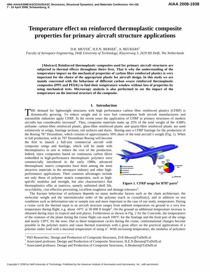
Figure 1. CFRP usage for B787 parts2
Temperature effect on reinforced thermoplastic composite properties for primary aircraft structure applicati ons
D.R. MEYER*, H.E.N. BERSEE†, A. BEUKERS‡ Faculty of Aerospace Engineering, Delft University of Technology, Kluyverweg 3, 2629 HS Delft, The Netherlands
[Abstract] Reinforced thermoplastic composites used for primary aircraft structures are subjected to thermal effects throughout theirs lives. That is why the understanding of the temperature impact on the mechanical properties of carbon fibre reinforced plastics is very important for the choice of the appropriate plastic for aircraft design. In this study we are mainly concerned with the behaviour of different carbon weave reinforced thermoplastic composites (PPS and PEEK) to find their temperature window without loss of properties by using mechanical tests. Microscopy analysis is also performed to see the impact of the temperature on the internal structure of the composite.
I. Introduction HE demand for lightweight structures with high performance carbon fibre reinforced plastics (CFRP) is dynamically growing. To reduce weight and to save fuel consumption both aircraft manufacturers and
automobile industries apply CFRP. In the recent years the application of CFRP in primary structures of modern aircrafts has considerably increased1. Thus, composite materials make up 25% of the total weight of the A380's airframe: carbon-fibre reinforced plastic, glass-fibre reinforced plastic and quartz-fibre reinforced plastic are used extensively in wings, fuselage sections, tail surfaces and doors. Boeing uses a CFRP fuselage for the production of the Boeing 787 Dreamliner, which consists of approximately 50% share of the total aircraft’s weight (Fig. 1). When in full production, with its 787 Dreamliner Boeing will become the first to launch a full-size commercial aircraft with composite wings and fuselage, which will be made with thermoplastics in aim to reduce the cost of the production. Indeed, since composites based on continuous carbon fibres embedded in high-performance thermoplastic polymers were commercially introduced in the early 1980s, advanced thermoplastic matrix composites have been among the most attractive materials in the aerospace industry and other high-performance applications. Their common advantages include not only those of polymer matrix composites, such as high-specific modulus and strength, but also characteristics that thermoplastics offer as matrices, namely unlimited shelf life, recyclability, cost effective processing, excellent toughness and damage tolerance3.
The fracture behaviour of polymers depends on many molecular factors such as the chain architecture, the molecular weight and the intermolecular order of the polymer (such as crystallinity), and in addition on test conditions such as deformation rate or sample size and more important in the case of our study, temperature. During a cruise cycle the thermal input to an aircraft structure ranges from ambient temperature on ground to a very low temperature during flight, e.g. about -50°C at 30 000 ft height4. On the ground an additional temperature increase is obtained during stays in tropical and arid places. Furthermore as shown in Fig. 2 for the Concorde, the temperatures of the contours of the plane during the cruise flight can reach 100°C for the fuselage and the front part of the wings and nearly 130°C for the nose. Due to these temperature cycles during the cruise, conformational changes become possible in the polymer matrix and cause thermal transitions with a great affect on the practical applications of a polymer under load with a maximal temperature of using it5. With increasing temperature, the modulus of polymers * PhD Researcher, Design and Production of Composite Structures, [email protected] † Associated professor, Design and Production of Composite Structures, [email protected] ‡ Associated professor, Design and Production of Composite Structures, [email protected]
T
49th AIAA/ASME/ASCE/AHS/ASC Structures, Structural Dynamics, and Materials Conference <br> 16t7 - 10 April 2008, Schaumburg, IL
AIAA 2008-1938
Copyright © 2008 by Delft University of Technology. Published by the American Institute of Aeronautics and Astronautics, Inc., with permission.

Figure 2. Temperature contours on the Concorde during cruise flight6
generally decreases, although thermal transitions occur which can impart a dramatic step-change in stiffness over a relatively small range of temperatures. Experimental studies have been made previously to describe the effects of temperature on polymer matrix composites: it was recently shown that for a unidirectional reinforced composite a temperature level beyond the glass transition point of the matrix material causes some change in the structural behaviour from an elastic to a thermo-viscoelastic or a thermo-plastic one with loss of stiffness, strength7-9 and bending fracture stress10. Therefore, the influence of the viscoelastic matrix cannot be ignored. The thermoplastic must be consequently chosen to have a sufficient high glass transition temperature. Only few works were done for woven carbon fibre reinforced composites in this range of temperatures, which is the reason of the importance of our study. Woven carbon fibre reinforced composites have better impact properties than unidirectional reinforced composites and so can be used for primary impact-prone aircraft structures.
On the other hand side, if the temperature is decreased below Tg, the mechanical behaviour of polymers, and thus of the associated composite, can change from a ductile deformation to a brittle fracture for a typical engineering plastic, and consequently a decrease of the mechanical properties takes place11. The temperature above which a material deforms in a ductile manner and below which it fractures in a brittle manner is called the ductile-to-brittle transition temperature TDB. In general the transition from brittle to ductile fracture behaviour is explained by the existence of two different failure mechanisms, one leading to brittle failure and one leading to ductile shear yielding. In this scheme, known as the Ludwig–Davidenkov–Orowan hypothesis12, the failure mechanism that requires the lowest stress under certain conditions is the one determining the failure mechanism: when the yield stress is lower than the brittle failure stress, ductile failure occurs, when the brittle stress is lower, brittle failure occurs. Because the brittle failure mechanism is less temperature dependent than the yield stress, which decreases strongly with increasing temperature, a temperature exists above which the failure behaviour becomes ductile. Few experimental studies were done for such low temperatures11,13, our study will allow determining the real impact of low temperatures on the mechanical properties of thermoplastics composites.
The mechanical fracture behaviour of materials under specified testing conditions is often sufficiently described by the corresponding value of TDB. If the temperature a material encounters during use (Tuse) is higher than the TDB of the material, it will not fail in a brittle manner. In general the TDB of a material is found below the glass transition temperature Tg. Above Tg, the modulus of a polymer is very low, unless the material is highly cross-linked or highly crystalline. Consequently, for a polymer to have a sufficiently high hardness it is often necessary that Tuse is well below Tg. For these reasons, the difference between Tg and TDB is an important material parameter as it determines the temperature range where a material can be used (in the ideal case: TDB < Tuse < Tg).
The use of thermoplastics for the conception of the wings and the complete fuselage leads to the use of very high temperature resistant polymers, such as poly(ether ether ketone) (PEEK) and poly(phenylene sulfide) (PPS). Poly(ether ether ketone) is a semi-crystalline polymer with a crystalline melting point around 335°C and a glass transition at around 145°C14. PEEK has excellent solvent resistance, being completely soluble at room temperature only in concentrated sulfuric acid14. Poly(phenylene sulfide) is an important engineering polymer which has been the focus of intensive research for the past two decades. PPS, which is a semi-crystalline polymer with Tg around 85°C and a melting temperature Tm of about 285°C15, is considered to possess inherent fire resistant and excellent solvent and chemical resistance. The highly stable chemical bonds of the molecular structure of these polymers impart a remarkable degree of molecular stability toward both thermal degradation and chemical reactivity, as show in Fig. 3, with the thermogravimetric analysis which indicated that both thermoplastics are quite thermally stable until a temperature of 500°C.
0
20
40
60
80
100
0 200 400 600 800
Temperature, °C
Wei
ght l
oss,
%
PEEKPPS
Figure 3. Comparative Thermogravimetric Analysis of PEEK and PPS
under air at a heating rate of 10°C/min
The aim of the study is to determine the range of using temperature (Tuse) of both woven carbon fibre reinforced PPS and PEEK composites by investigating the effect of changing temperature on their mechanical performance (in-plane shear and flexural stress and moduli) and their failure behaviour by microscopy.
II. Experimental
A. Materials and laminates preparation Materials were provided by Ten Cate Advanced Composite, The Netherlands, as 5H woven carbon thermoplastic
semipregs. Squares of 58 cm x 58 cm were cut to prepare the laminates. According to the standard tests used for determining the mechanical properties, two different sorts of laminates were prepared for each thermoplastic, one with 8 layers of semipregs and second one with 14 layers.
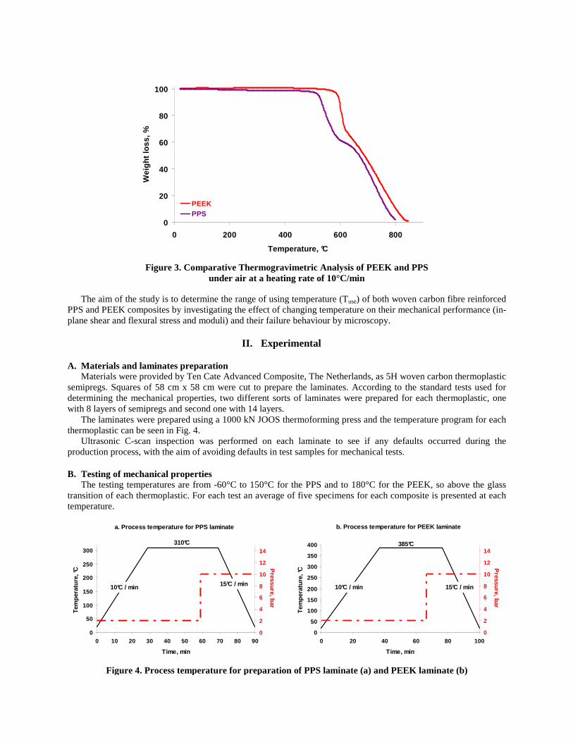
The laminates were prepared using a 1000 kN JOOS thermoforming press and the temperature program for each thermoplastic can be seen in Fig. 4.
Ultrasonic C-scan inspection was performed on each laminate to see if any defaults occurred during the production process, with the aim of avoiding defaults in test samples for mechanical tests.
B. Testing of mechanical properties The testing temperatures are from -60°C to 150°C for the PPS and to 180°C for the PEEK, so above the glass
transition of each thermoplastic. For each test an average of five specimens for each composite is presented at each temperature.
a. Process temperature for PPS laminate
0
50
100
150
200
250
300
0 10 20 30 40 50 60 70 80 90
Time, min
Tem
pera
ture
, °C
0
2
4
6
8
10
12
14
Pressure, bar
10°C / min 15°C / min
310°C
b. Process temperature for PEEK laminate
0
50
100
150
200
250
300
350
400
0 20 40 60 80 100
Time, min
Tem
pera
ture
, °C
0
2
4
6
8
10
12
14
Pressure, bar
10°C / min 15°C / min
385°C
Figure 4. Process temperature for preparation of PPS laminate (a) and PEEK laminate (b)

1) Flexural tests The flexural tests are performed on a MTS 10 kN elastomer test system. The environmental chamber used for the
tests is a Thermotron FR-1-CH-LN2. The temperature controller MTS 409.80 inside the chamber allows a value within 1°C of the set value. This chamber is also a circulating air oven and incorporated a liquid nitrogen supply to allow sub-ambient temperatures to be reached. After the chamber is cooled/heated to testing temperature, the temperature is held for 2 hours to allow uniform temperature within the specimens.
The 3-point bending flexural test is performed according to the ASTM D7264-07 procedure. The size of the specimens is 13 mm x 160 mm and the thickness is 4.2 mm (14 layers thick). The crosshead speed is 1 mm/min.
2) In-plane shear tests All the in-plane shear tests are performed on a Zwick 250 kN testing system. To achieve the desired range of
testing temperature, an EC1760 environmental chamber is fitted to the testing machine. The temperature controller Eurotherm 2404CG inside the chamber allows a value within 2°C of the set value. This chamber is a circulating air oven with a liquid nitrogen supply to allow sub-ambient temperatures to be reached. After the chamber is cooled/heated to testing temperature, the temperature is held for 30 minutes to allow uniform temperature within the specimen.
In-plane shear testing is performed according to the ASTM D3518-94(01) procedure. The testing parameters used are 2 mm/min loading rate and 50 mm for the gauge length. An extensometer was fitted to the specimen to provide accurate measurement of the materials shear stress and modulus. The specimens’ thickness is 2.4 mm – 8 layers – and their size is 25 mm wide and 250 mm long. Tabs are not required for successful conduct of these tests.
C. Microscopy After performing the tests, a microscopy analysis is done on the fracture region of the specimens to see the
temperature influence on the formation of cracks between the layers. The failures of the samples are determined through visual inspection using a Zeiss Axiovert 40 Mat microscope
2.5X with CCD camera projective 0.5x.
D. High-speed failure measurement A high-speed digital camera, Vision Research Phantom v5.0, is used during the flexural tests to determine the failure mode by recording slow-motion playback of the tests. The speed was set to 500 frames per second.
III. Results and discussion
A. Ultrasonic C-scan analysis Figure 5 shows the C-scanning results obtained for 8 layers PPS and PEEK laminates. The results are similar for
the 14 plies laminates and it can be seen that there are no real defects are found on these laminates. By consequence the process used for preparing both PPS and PEEK laminates is considered acceptable as the thickness of each laminate is uniform.
B. PPS Laminates PPS flexural stress and modulus are calculated for each test from the data obtained, and plotted as a function
of the temperature (Fig. 6). The flexural stress decreases already before the PPS glass transition temperature, Tg, but when this transition temperature is reached, the decrease is much faster, and results in a complete loss of the flexural
a) b)
Figure 5. C-scanning analysis of 8 plies PPS laminates (a) and 8 plies PEEK laminates (b)

strength in a small range of temperatures, which is typical of many semi-crystalline polymers13. For the sub-ambient temperature, the flexural stress does not seem to be greatly affected by the temperature. By consequence, the ductile-to-brittle transition of PPS is lower than -60°C and this thermoplastic can be used until this temperature range. The flexural modulus is quite stable from low temperatures to the Tg, above which it decreases very fast. However, the modules starts increasing in the 120°C-130°C temperature range, probably due to the cold crystallization of the thermoplastic matrix, which takes place at 125°C15. Indeed, in that transition region, the matrix passes from a rubber-like to a solid-like state, with crystallization of the amorphous part of PPS. The matrix becomes by consequence tougher because of the morphology change inside the matrix, and so the flexural modulus increases. The high-speed camera has only been used at room temperature, i.e. 20°C, which was the only test performed outside of the climate chamber. Figure 7 shows that at the break point some buckling occurs at the compression side of the specimen. The failure mode is clearly in tension, with a propagation of the crack through the different plies in a very short time, only a few microseconds, too fast for only a visual analysis of the failure mode. It can also be
a)
300
400
500
600
700
800
900
1000
1100
1200
-70 -50 -30 -10 10 30 50 70 90 110 130 150
Temperature, °C
Fle
xura
l str
ess,
MP
a
Tg = 85°C
b)
80
85
90
95
100
105
110
-70 -50 -30 -10 10 30 50 70 90 110 130 150
Temperature, °C
Fle
xura
l mod
ulus
, GP
a
Tg = 85°C
Figure 6. PPS flexural stress (a) and flexural modulus (b) versus temperature
a) T0 b) To + 24ms
c) T0 + 26ms d) To + 40ms
Figure 7. High-speed camera pictures, taken at different times during testing at 20°C

noticed that a small delamination occurred between the layers at that temperature. To have a better understanding of the break behavior, microscopic analyses are performed on the failure points
for different temperatures (Fig. 8). At 20°C, the delamination between the first few layers is confirmed at the tension side, and at the compression side some buckling occurs. It can be seen on Fig. 8b that for this temperature a lot of micro-cracks occur in the different layers of resin near the breaking point. These micro-cracks are only present in this area, not in the other parts of the specimen, and are induced during failure. The occurrence of these cracks can be due to the release of the residual stresses produced by the production of the laminate16. Parlevliet et al.17 point out that for semi-crystalline thermoplastics, these residual stresses are due to densification upon crystallization (with crystals being of higher density than the amorphous phase). Consequently, when the failure occurs, the breaking energy propagates through the layers and the presence of these residual stresses results of the formation of these micro-cracks. When the testing temperature decreases, e.g. for -40°C (Fig 8a), there is no more buckling on the compression side, and no tension failure on the tension side. The failure is now due to interlaminar shear on both sides, and this delamination becomes bigger with lower temperatures and propagates nearly through half of the specimen’s length. There is a complete change in the failure mode; the polymer matrix seems to be less ductile than at ambient temperature, but without reaching the ductile-to-brittle transition area. This result is very important as, in aeronautical applications, composite plates are sensitive to impact, and delaminations can occur readily in composite laminates on impact and under fatigue after impact18. Consequently, at low temperatures, the delamination can still be more effective for PPS composite. On the other hand, increasing the temperature changes the failure mode: at 60°C (Fig 8c) the failure is clearly a tensile failure with crack propagation through the layers, and on the compression side some buckling occurred, but no interlaminar shear is present near the failure area. At 80°C, near the PPS Tg, the tensile failure is still present but
a) b)
c) d)
e) f)
Figure 8. PPS flexural failure cross-ply surfaces showing tension and compression areas at -40°C (a), 20°C (b), 60°C (c), 80°C (d), 100°C (e) and 120°C (f)

the crack is less important in width than at lower temperatures. The matrix begins to pass through a thermo-viscoelastic phase and so its properties change completely, as it becomes more ductile. This is confirmed with the specimen tested at a temperature above Tg, i.e. 100°C (Fig 8e). It can be seen that both the tensile and compression failure, are consequently reduced because of the higher ductility of the polymer. These results therefore correlate with the work of Kym and Ye19. They pointed that the major effect of elevated temperature is to change matrix toughness and ductility, which is evidently the cause for the temperature dependence of failure behavior. These results support as well the work of Adachi et al20. They found that for flexural tests the fracture changed from brittle to ductile near the Tg, with a difference of the fracture surfaces. By consequence, the brittle fracture is considered to be related to the glassy state and the ductile fracture to the rubbery state. The temperature is by consequence an important aspect to be observed during realization of the tests.
This viscoelasticity has also another effect on the internal structure: it can be seen that with increasing temperature, the micro-cracks present in the polymer layers are reduced and are not present for temperatures above the Tg. By increasing the temperature above the glass transition, possible residual stresses due to buildup can be relaxed, because, at these temperatures, the molecular chains possess enough energy for freedom of movement 17. In consequence, the breaking energy can not initiate micro-cracks at temperature higher than Tg.
At the PPS crystallization temperature, i.e. 120°C, the failure behavior changes again. As shown before in Fig. 6b, the flexural modulus increases at the crystallization temperature. The consequence on the failure mode is that crack propagation occurs more readily through the layers as the matrix becomes more brittle, but without any tensile failure or buckling (Fig. 8f). PPS shear stress and modulus have been deduced from the in-plane shear curves, and have been plotted as a function of the temperature in Fig. 9. The behavior of PPS is different compared to the flexural tests in that the shear stress decreases continuously with the temperature. However, above 30°C, so around 50°C below the PPS Tg, the slope of the curve becomes higher. The same behavior is found also for the shear modulus. Above 40°C, a complete loss of the shear modulus occurs before the glass transition area. For temperatures well above the glass transition, only values of 15% of the shear modulus at room temperature are found. These results are quite different compared to the ones found for the flexural stress and modulus. Indeed, for these curves, it had been found that both flexural parameters decreased slightly at the glass transition temperature. It must be understood that the flexural test is a combination of tension and compression as well as shear21. While looking at the shear stress and modulus, it is clear that the shear parameter is the most critical one, and the one which has the least effect on the flexural test. Furthermore, at the PPS crystallization temperature, no change occurs for the shear modulus and the values become quite stable. The shear parameter is consequently less dependent on the crystallinity of the matrix than the flexural one.
C. Results on PEEK The results found for the PEEK flexural stress and modulus are similar to the PPS ones (Fig 10). Indeed, from room temperature to PEEK Tg, the flexural stress decreases slightly, due to the ductility of the resin at that temperature. These results therefore support the work of Schmitt-Thomas et al22. They found that for a PAEK
a)
60
70
80
90
100
110
120
130
140
150
160
-70 -50 -30 -10 10 30 50 70 90 110 130 150
Temperature, °C
She
ar s
tres
s, M
Pa
Tg = 85°C
b)
0
2
4
6
8
10
12
14
16
18
-70 -50 -30 -10 10 30 50 70 90 110 130 150
Temperature, °C
She
ar m
odul
us, G
Pa
Tg = 85°C
Figure 9. PPS shear stress (a) and shear modulus (b) versus temperature
reinforced composite, increasing the temperature makes change the failure behavior from a brittle mode at room temperature to a ductile mode for higher temperatures than Tg.
The flexural modulus follows the same behavior than the flexural stress of PPS; it is quite stable until the glass transition, above which one it decreases.
a)
400
500
600
700
800
900
1000
1100
1200
1300
-70 -50 -30 -10 10 30 50 70 90 110 130 150 170 190Temperature, °C
Fle
xura
l str
ess,
MP
aTg = 145°C
b)
70
75
80
85
90
95
100
105
110
115
120
-70 -50 -30 -10 10 30 50 70 90 110 130 150 170 190
Temperature, °C
Fle
xura
l mod
ulus
, GP
a
Tg = 145°C
Figure 10. PEEK flexural stress (a) and flexural modulus (b) versus temperature
a) b) c)
d) e)
f) g)
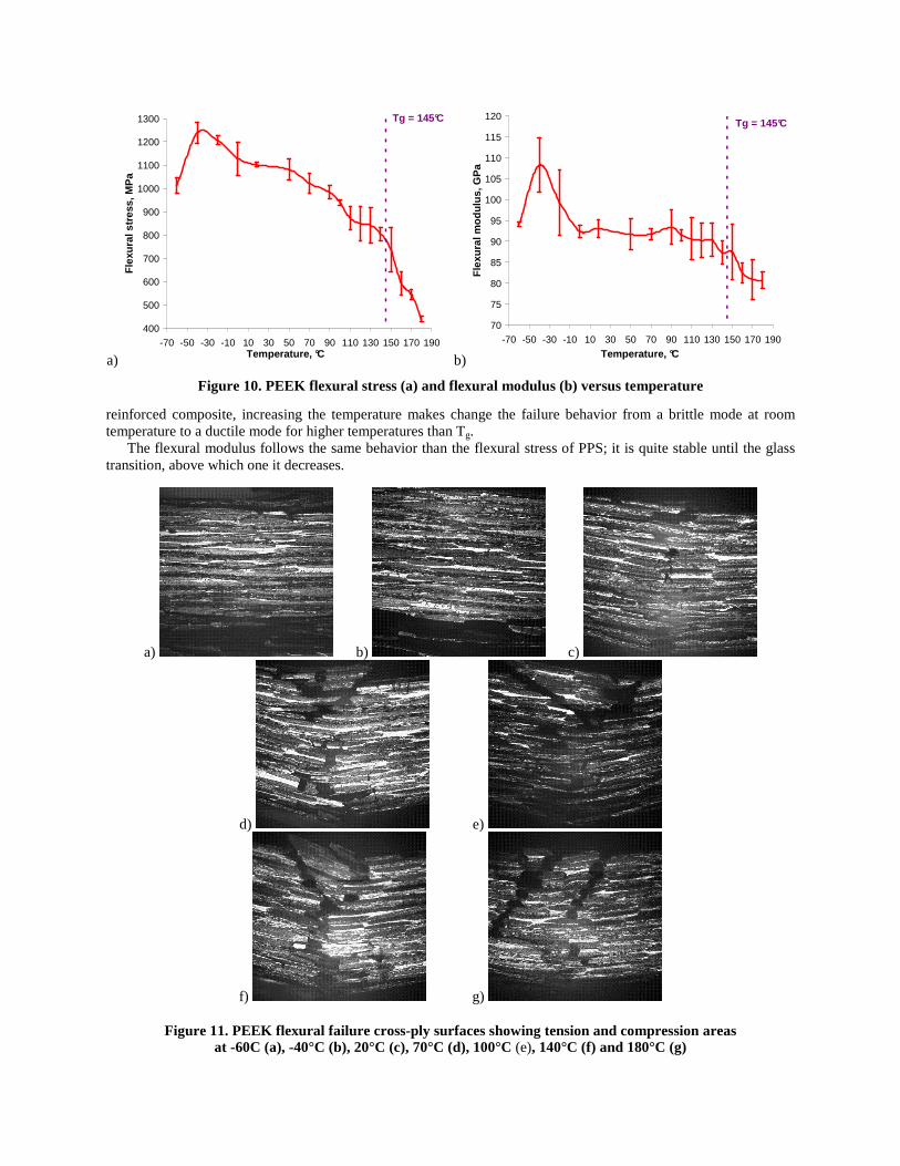
Figure 11. PEEK flexural failure cross-ply surfaces showing tension and compression areas at -60C (a), -40°C (b), 20°C (c), 70°C (d), 100°C (e), 140°C (f) and 180°C (g)
When decreasing to sub-ambient temperatures, the flexural stress and modulus increase, until it drops to lower values for a temperature of -60°C. This result correlates with the work of Adams et al23. According to them, this drop of the values of flexural parameters can be due to the ß transition of the PEEK, which takes place at -60°C24, so well below the PEEK Tg. This ß transition, which can be seen as the ductile-to-brittle transition, is less intense than the Tg and is caused by the “crankshaft” rotation of segments of the polymer chain23. The PEEK resin is still a useful engineering material above the ß transition temperature, and so PEEK composite can be used until this temperature range. The microscopic analyses for PEEK specimens show the same phenomenon compared to PPS results (Fig. 11): for low temperatures, some interlaminar shear occurs on both the tension and compression sides (Fig. 11a and b). The specimens tested below the ß transition seem to be more brittle than the one tested at -40°C, which is the result of the transition. Then, by increasing the temperature, the failure changes to a tensile failure with some buckling on the compression side. These two failures become less marked when reaching the glass temperature (Fig. 11f). In the same way, the micro-cracks are less present in the specimen structures at temperatures above the glass transition temperature. As for the PPS, the polymer becomes more ductile above this transition.
IV. Conclusion
This paper has examined the temperature dependence of fracture toughness for PPS and PEEK composites at different temperatures. It was found that failure behavior of both thermoplastic composites is closely related to temperature. With increase in temperature, the failure behavior is changed from a brittle mode at room temperature to a ductile mode above the glass transition temperature. This ductility induces a loss of flexural modulus and stresses above that area and also a reducing of the micro-crackings in the internal structure of the specimens. Thus, the fracture phenomenon of PPS and PEEK is strongly dependent on their thermo-viscoelastic characteristics and can be predicted for a wide range of temperatures.
It was also found that the shear is the most critical parameter, compared to the flexure one, as there is already a drop of the values around 40°C below the glass transition temperature. It is also less dependent of the crystallinity of the matrix.
If we look at the data for both PPS and PEEK flexural tests, it can be concluded that both thermoplastics can be used above -60°C and to their glass transition temperatures without loosing too much properties. This result is really important as this low temperature is the thermal input to an aircraft structure at very high height4. For temperatures higher than the glass transition, their utilization will depend on the composite properties required for the specific application.
Acknowledgments D.R. Meyer would like to thank Ten Cate Advanced Composites for providing the different carbon
thermoplastics semipregs used for preparing the laminates for the mechanical tests, and also Renato Carbone for performing the different tests.
References 1Herrmann A.S., Baisch P., Das “virtuelle Modell” zur CFK-Produkt und Prozessgestaltung, in conference proceedings of
the DGLR Conference, Friedrichshafen, September 2005 2Boeing Company, Chicago, 2007 3Offringa A.R., “Thermoplastic composites - rapid processing applications”, Composites Part A, 1996, 27A:329–36 4Petersen D., Rolfes R., Zimmermann R., Thermo-mechanical design aspects for primary composite structures of large
transport aircraft, Aerosp. Sci. Technol. 5, pp135–146, 2001 5Miyano Y., McMurray M.K., Kitade N., Makada M., Loading rate and temperature dependence of flexural behaviour of
unidirectional pitch-based CFRP laminates, Composites 26, 713-717, 1995 6“Accelerated Aging of Materials and Structures: The Effects of Long-Term Elevated-Temperature Exposure”, National
Materials Advisory Board, 1996 7Mahieux C.A., Reifsnider K.L., Case S.W., Property modeling across transition temperatures in PMC’s: Part I. Tensile
Properties, Applied Composite Materials, 8, 217-234, 2001 8Bosze E.J., Alawar A., Bertschger O., Tsai Y.-I., Nutt S.R., High-temperature strength and storage modulus in
unidirectional hybrid composites, Composites Science and Technology, 66, 2006, 1963-1969 9Walther B.M., An Investigation of the Tensile Strength and Stiffness of Unidirectional Polymer-Matrix, Carbon-Fiber
Composites under the Influence of Elevated Temperatures, Virginia Tech, Blacksburg, 1998

10Morioka K., Tomita Y., Takigawa K., High-temperature fracture properties of CFRP composite for aerospace applications, Materials Science and Engineering A319-321, 2001, 675-678
11Vlasveld D.P.N., Vaidya S.G., Bersee H.E.N., Picken S.J., A comparison of the temperature dependence of the modulus, yield stress and ductility of nanocomposites based on high and low MW PA6 and PA66, Polymer, Vol. 46, Issue 10, pp3452-3461
12Ward I.M., Hadley D.W., An introduction to the mechanical properties of solid polymers, New York: Wiley, 1997 13Frassine R., Rink M., Pavan A., Fracture behavior of thermoplastic matrix composites: II. Rate and temperature
dependence, in unidirectional PEEK/Carbon-fibre laminates, Composites Science and Technoloy, 1253-1260, 1996
14Attwood T.E., Dawson P.C., Freeman J.L., Hoy L.R.J., Rose J.B., Staniland P.A., Synthesis and properties of polyaryletherketones, Polymer1981, Vol. 22, 1096
15Seo K.H., Park L.S., Baek J.B., Brostow W., Thermal behaviour of poly(phenylene sulfide) and its derivatives, Polymer 1993, Vol. 34, Issue 12
16Parlevliet P.P., Bersee, H.E.N., Beukers A., Residual stresses in thermoplastic composites – a study of the literature. Part III: effects of the thermal residual stresses, Composites: Part A, 1581-1596, 2007
17Parlevliet P.P., Bersee, H.E.N., Beukers A., Residual stresses in thermoplastic composites – a study of the literature. Part I: formation of residual stresses, Composites: Part A, 1847-1857, 2006
18Blanco N., Gamstedt E.K., Asp L.E., Costa J., Int. J. Solids Struct. 41, 4219-4235, 2004 19Kim K.-Y., Ye L., Composites Part A 35, 477-487, 2004 20Adachi T., Osaki M., Yamaji A., Gamou M., A Time–temperature dependence of the fracture toughness of a
poly(phenylene sulphide) polymer, Proc. Instn Mech. Engrs Vol.217 Part L: J. materials: Design and Applications, 2002 21Standart test method for flexural properties of polymer matrix composite materials, D7264-07 22Schmitt-Thomas K.G., Yang Z.-G., Malke R., Failure behaviour and performance analysis of hybrid-fiber reinforced
PAEK composites at high temperature, Composites Science and Technology, 1509-1518, 1998 23Adams R.D., Gaitonde J.M., Low-temperature flexural dynamic measurements on PEEK, HTA and some of their carbon
fibre composites, Composites Science and Technology 47, 271-287, 1993 24Seferis J.C., Polyetheretherketone (PEEK): processing-structure and properties for a matrix in high performance
composites, Polymer Composites 7, 158-169, 1986