Embed Size (px)
Citation preview

The International Authority on Air System Components
AIR MOVEMENT AND CONTROLASSOCIATION INTERNATIONAL, INC.
AMCA Publication 511-10
(Rev. 11-13)Certified Ratings Program Product Rating Manual for
Air Control Devices

AMCA Publication 511-10 (Rev. 11-13)
Certified Ratings ProgramProduct Rating Manual for Air Control Devices
Air Movement and Control Association International30 W. University Drive
Arlington Heights, Illinois60004

AMCA International Publication 511-10 was approved by the membership of the Air Movement and Control Association International on October 14, 2010.
The August 2012 revision was approved on August 1, 2012.
The November 2013 revision was approved on November 18, 2013.
© 2013 by Air Movement and Control Association International Inc.
All rights reserved. Reproduction or translation of any part of this work beyond that permitted by Sections 107 and 108 of the United States Copyright Act without the permission of the copyright owner is unlawful. Requests for permission or further information should be addressed to the executive director, Air Movement and Control Association International Inc. at 30 West University Drive, Arlington Heights, IL 60004-1893 U.S.A.
Air Movement and Control Association International Inc. will consider and decide all written complaints regarding its standards, certification programs or interpretations thereof. For information on procedures for submitting and handling complaints, write to:
Air Movement and Control Association International30 West University DriveArlington Heights, IL 60004-1893 U.S.A.
AMCA International Incorporatedc/o Federation of Environmental Trade Associations2 Waltham Court, Milley Lane, Hare HatchReading, Berkshire, United KingdomRG10 9TH
AMCA uses its best efforts to produce publications for the benefit of the industry and the public in light of available information and accepted industry practices. However, AMCA does not guarantee, certify or assure the safety or performance of any products, components or systems tested, designed, installed or operated in accordance with AMCA publications or that any tests conducted under its publications will be non-hazardous or free from risk.
AMCA Publications
Authority
Copyright
Objections
Disclaimer

Marty Gissel Greenheck Fan CorporationCommittee Chair
Mike Binkholder Mestek Inc.
Jeff Blake Construction Specialties Inc.
Dane Carey United Enertech
Eric Gohring Cesco Products
Jason George Ruskin Company
Doug Graham T. A. Morrison & Co. Inc.
Dan Huber Ruskin Company
Larry Kozak Ward Industries
Vince Kreglewicz Arrow United
Tim Malki Daniel Mechanical Co.
Bin Ngo Daniel Mechanical Co.
Dan Rau Ruskin Company
Robert Van Becelaere Ruskin Company
Tim Orris AMCA International
John Pakan AMCA International
Review Committee

Related AMCA Documents
AMCA Publication 11 Certified Ratings Program Operating Manual
AMCA Publication 111 Laboratory Accreditation Program
AMCA Publication 512 AMCA Listing Label Program
ANSI/AMCA Standard 500-D Laboratory Methods for Testing Dampers for Rating
ANSI/AMCA Standard 500-L Laboratory Methods for Testing Louvers for Rating
ANSI/AMCA Standard 540 Test Method for Louvers Impacted by Wind Borne Debris
ANSI/AMCA Standard 550 Test Method for High Velocity Wind Driven Rain Resistant Louvers
RelatedPublications
RelatedStandards
1. Purpose . . . . . . . . . . . . . . . . . . . . . . . . . . . . . . . . . . . . . . . . . . . . . . . . . . . . . . . . . . . . . . . . . . . . . . . . . . . . . . . . . . . . . . . . . 1
2. Scope. . . . . . . . . . . . . . . . . . . . . . . . . . . . . . . . . . . . . . . . . . . . . . . . . . . . . . . . . . . . . . . . . . . . . . . . . . . . . . . . . . . . . . . . . . . 1
3. Definitions and Symbols . . . . . . . . . . . . . . . . . . . . . . . . . . . . . . . . . . . . . . . . . . . . . . . . . . . . . . . . . . . . . . . . . . . . . . . . . . . 1
3.1 Definitions . . . . . . . . . . . . . . . . . . . . . . . . . . . . . . . . . . . . . . . . . . . . . . . . . . . . . . . . . . . . . . . . . . . . . . . . . . . . . . . . . . . 1
3.2 Symbols . . . . . . . . . . . . . . . . . . . . . . . . . . . . . . . . . . . . . . . . . . . . . . . . . . . . . . . . . . . . . . . . . . . . . . . . . . . . . . . . . . . . . 2
4. Data Submittal Requirements . . . . . . . . . . . . . . . . . . . . . . . . . . . . . . . . . . . . . . . . . . . . . . . . . . . . . . . . . . . . . . . . . . . . . . . 2
5. Required Catalog Statements . . . . . . . . . . . . . . . . . . . . . . . . . . . . . . . . . . . . . . . . . . . . . . . . . . . . . . . . . . . . . . . . . . . . . . . 2
5.1 Licensed product statement . . . . . . . . . . . . . . . . . . . . . . . . . . . . . . . . . . . . . . . . . . . . . . . . . . . . . . . . . . . . . . . . . . . . . . 2
5.2 Licensed performance statement. . . . . . . . . . . . . . . . . . . . . . . . . . . . . . . . . . . . . . . . . . . . . . . . . . . . . . . . . . . . . . . . . . 2
5.3 Appurtenances statement . . . . . . . . . . . . . . . . . . . . . . . . . . . . . . . . . . . . . . . . . . . . . . . . . . . . . . . . . . . . . . . . . . . . . . . 2
6. General Guidelines for Air Control Products. . . . . . . . . . . . . . . . . . . . . . . . . . . . . . . . . . . . . . . . . . . . . . . . . . . . . . . . . . . 3
6.1 Manufacturer’s responsibility . . . . . . . . . . . . . . . . . . . . . . . . . . . . . . . . . . . . . . . . . . . . . . . . . . . . . . . . . . . . . . . . . . . . . 3
6.2 AMCA staff responsibility . . . . . . . . . . . . . . . . . . . . . . . . . . . . . . . . . . . . . . . . . . . . . . . . . . . . . . . . . . . . . . . . . . . . . . . . 3
6.3 Rating development . . . . . . . . . . . . . . . . . . . . . . . . . . . . . . . . . . . . . . . . . . . . . . . . . . . . . . . . . . . . . . . . . . . . . . . . . . . . 3
6.4 Aerodynamically similar products. . . . . . . . . . . . . . . . . . . . . . . . . . . . . . . . . . . . . . . . . . . . . . . . . . . . . . . . . . . . . . . . . . 3
6.5 Nameplated products . . . . . . . . . . . . . . . . . . . . . . . . . . . . . . . . . . . . . . . . . . . . . . . . . . . . . . . . . . . . . . . . . . . . . . . . . . . 3
7. Check Test Tolerances and Required Tests. . . . . . . . . . . . . . . . . . . . . . . . . . . . . . . . . . . . . . . . . . . . . . . . . . . . . . . . . . . . 3
7.1 Licensee’s duty . . . . . . . . . . . . . . . . . . . . . . . . . . . . . . . . . . . . . . . . . . . . . . . . . . . . . . . . . . . . . . . . . . . . . . . . . . . . . . . 3
7.2 Tolerances . . . . . . . . . . . . . . . . . . . . . . . . . . . . . . . . . . . . . . . . . . . . . . . . . . . . . . . . . . . . . . . . . . . . . . . . . . . . . . . . . . . 3
7.3 Required tests . . . . . . . . . . . . . . . . . . . . . . . . . . . . . . . . . . . . . . . . . . . . . . . . . . . . . . . . . . . . . . . . . . . . . . . . . . . . . . . . 4
8. Louver | Air Performance Rating Requirements (page 1 of 2) . . . . . . . . . . . . . . . . . . . . . . . . . . . . . . . . . . . . . . . . . . . . . 5
8. Louver | Air Performance Rating Requirements (page 2 of 2) . . . . . . . . . . . . . . . . . . . . . . . . . . . . . . . . . . . . . . . . . . . . . 6
9. Louver | Wind-Driven Rain Rating Requirements . . . . . . . . . . . . . . . . . . . . . . . . . . . . . . . . . . . . . . . . . . . . . . . . . . . . . . . 7
10. Louver | Water Penetration Rating Requirements (page 1 of 2) . . . . . . . . . . . . . . . . . . . . . . . . . . . . . . . . . . . . . . . . . . 8
10. Louver | Water Penetration Rating Requirements (page 2 of 2) . . . . . . . . . . . . . . . . . . . . . . . . . . . . . . . . . . . . . . . . . . 9
11. Acoustical Louver | Sound Performance Rating Requirements . . . . . . . . . . . . . . . . . . . . . . . . . . . . . . . . . . . . . . . . . 10
12. Adjustable Louver | Air Leakage Rating Requirements . . . . . . . . . . . . . . . . . . . . . . . . . . . . . . . . . . . . . . . . . . . . . . . . 11
13. Damper | Air Performance Rating Requirements (page 1 of 2) . . . . . . . . . . . . . . . . . . . . . . . . . . . . . . . . . . . . . . . . . . 12
13. Damper | Air Performance Rating Requirements (page 2 of 2) . . . . . . . . . . . . . . . . . . . . . . . . . . . . . . . . . . . . . . . . . . 13
14. Volume Control Damper | Air Leakage Rating Requirements (page 1 of 2) . . . . . . . . . . . . . . . . . . . . . . . . . . . . . . . . 14
14. Volume Control Damper | Air Leakage Rating Requirements (page 2 of 2) . . . . . . . . . . . . . . . . . . . . . . . . . . . . . . . . 15
15. Ultra-Low Leakage Damper | Air Leakage Rating Requirements. . . . . . . . . . . . . . . . . . . . . . . . . . . . . . . . . . . . . . . . . 16
16. Bubble-Tight Damper | Air Leakage Rating Requirements. . . . . . . . . . . . . . . . . . . . . . . . . . . . . . . . . . . . . . . . . . . . . . 17
17. UL-Classified Damper | Air Leakage Rating Requirements . . . . . . . . . . . . . . . . . . . . . . . . . . . . . . . . . . . . . . . . . . . . . 18
18. Backdraft Damper | Air Leakage Rating Requirements . . . . . . . . . . . . . . . . . . . . . . . . . . . . . . . . . . . . . . . . . . . . . . . . 19
Contents

19. Gravity Ventilator (Excluding Louver Penthouses) | Air Performance Rating Requirements. . . . . . . . . . . . . . . . . . 20
20. Round Spiral Duct | Air Leakage Rating Requirements . . . . . . . . . . . . . . . . . . . . . . . . . . . . . . . . . . . . . . . . . . . . . . . . 22
21. Louver/Damper | Energy Efficiency Rating Requirements. . . . . . . . . . . . . . . . . . . . . . . . . . . . . . . . . . . . . . . . . . . . . . 23
22. Transverse Duct Connectors | Air Leakage Rating Requirements (page 1 of 2) . . . . . . . . . . . . . . . . . . . . . . . . . . . . 24
22. Transverse Duct Connectors | Air Leakage Rating Requirements (page 2 of 2) . . . . . . . . . . . . . . . . . . . . . . . . . . . . 25
Annex A Electronic Catalogs (Normative). . . . . . . . . . . . . . . . . . . . . . . . . . . . . . . . . . . . . . . . . . . . . . . . . . . . . . . . . . . . . . 26
Annex B Measurements (Normative). . . . . . . . . . . . . . . . . . . . . . . . . . . . . . . . . . . . . . . . . . . . . . . . . . . . . . . . . . . . . . . . . . 28
Annex C Developing Air Control Product Catalogs (Informative) . . . . . . . . . . . . . . . . . . . . . . . . . . . . . . . . . . . . . . . . . . 31

AMCA 511-10 (Rev. 11-13) | 1
Certified Ratings ProgramProduct Rating Manual for Air Control Devices
1. Purpose
AMCA Publication 511 dictates proper presentation of data and other required technical procedures for certification of air control devices under the AMCA Certified Ratings Program. This manual shall be used in conjunction with the current edition of AMCA Publication 11.
2. Scope
The products within the scope of this program are air control devices for use in general ventilation and air conditioning systems.
This program shall apply only to complete cataloged series of sizes. It shall not apply to individual sizes in a series, or part of a series of sizes, or to special units on which catalog ratings are not published.
The AMCA Certified Ratings seal shall be used only in connection with the specifically licensed device. The AMCA Seal shall be used only on complete units. The application of the AMCA seal to individual component parts, such as blades, frames, etc., is not permitted.
3. Definitions and Symbols
3.1 Definitions
All definitions found in AMCA Publication 11, as well as the definitions in this section, apply to this program.
3.1.1 AppurtenanceAppurtenance is any item in the air stream or on the inlet or discharge of the air control device that may affect the perfor-mance of the air control device.
An appurtenance shall be considered a part of the air control device if it is in place when the device is tested for perfor-mance rating and the effect of the appurtenance is included in the cataloged performance rating.
3.1.2 AMCA Certified Ratings ProgramThe Certified Ratings Program is a program for certifying a product’s performance ratings, as defined in this document.
3.1.3 Performance rating(s)Performance ratings are data generated from actual tested products used to derive the certified and published information.
3.1.4 Shall and shouldThe word “shall” indicates a mandatory requirement; the word “should” indicates an advisory statement.
3.1.5 Aerodynamically similarLouver and damper designs are considered to be aerody-namically similar if the profiles of the components in the air stream are geometrically similar. The blades shall be in rela-tive position to the frame and the center-to-center dimen-sions shall be the same. Frame, blade stops and blade profiles may have slight variances due to manufacturing methods. Blades must have the same streamline shape in that their leading and trailing edges shall be dimensionally equal. The overall angle or curvature of the blade must be the same. Slight deviations in material thickness shall not reduce the overall free area by more than 5% for damp-ers and 2.5% for louvers. Blade seals shall have the same profile, be of the same durometer and be secured to the blade in the same manner.
In addition to the requirements described above, louver or damper models claiming aerodynamic similarity for the purpose of certifying leakage performance shall meet the following criteria:
• The frames and blades shall have a modulus of elastic-ity (E) greater than or equal to the originally licensed model.
• The blade action (i.e., whether the damper is parallel or opposed blade) shall be the same as the originally licensed model.
• The method used for interconnecting the damper or louver blades (i.e., the linkage) shall be the same as the originally licensed model.
• The jamb seal shall be the same as the originally licensed model.
• The blade axle bearing assemblies shall be the same as the originally licensed model.
3.1.6 Volume control damperA volume control damper is a device which, when mounted to a duct or opening, is used to vary the volume of air through the duct or opening. It can be operated manually or mechanically and may have one or more blades.
For the purposes of this document, dampers meeting the definition of a backdraft damper or a UL-classified damper shall not be considered a volume control damper. Ultra-low-leakage dampers and bubble-tight dampers may be tested as volume control dampers.

2 | AMCA 511-10 (Rev. 11-13)
3.1.7 Backdraft damperA backdraft damper is a damper which, when mounted in a duct or opening, permits airflow in one direction and prevents airflow in the opposite direction.
3.1.8 UL-Classified damperFor the purpose of this document, a UL-classified damper is a device which is classified to Underwriters Laboratories category code EMME (Dampers for Fire Barriers and Smoke Applications) as a smoke damper, combination fire and smoke damper, or corridor damper.
3.1.9 Ultra-low-leakage damperThis is a device that leaks 35.2 L/s/m2 (6.93 cfm/ft2) or less at a static pressure differential of 3.0 kPa (12 in. wg). Leakage performance of ultra-low-leakage dampers may be certified at any static pressure differential 3.0 kPa (12 in. wg.) or greater as long as the leakage does not exceed 2 × (DPs)
0.5.
3.1.10 Bubble-tight damperA bubble-tight damper is a device whose leakage perfor-mance at the tested pressure meets the requirements of the bubble test as described in ANSI/AMCA 500-D.
3.2 Symbols
Symbol Description
DPs Pressure drop or pressure differential
4. Data Submittal Requirements
AMCA staff shall accept test data obtained in only the AMCA laboratory or an AMCA-accredited laboratory. Test data shall conform to the test standard used.
For each air control device and certification type covered by this program, a separate section of testing and rating requirements is included. The specific procedures and test data necessary for preparing performance ratings are defined in Sections 8 through 21.
The following data shall be submitted with all CRP-5 appli-cation forms:
• Results of the test(s), corrected to standard air density, where applicable
• Photograph of each test setup• Performance curve(s) of the test results, with test points
identified• Dimensional drawings• For all louvers, one additional drawing as shown in Annex B. • For louvers tested with a drain pan, one additional draw-
ing showing the height and setback dimensions of the drain pan
• For gravity ventilators, one additional drawing as shown in Section 19
5. Required Catalog Statements
5.1 Licensed product statement
The following statement shall be printed prominently and immediately adjacent to the reproduction of the AMCA Certified Ratings seal:
“[Licensee’s name] certifies that the [product designation] shown hereon [or herein] is licensed to bear the AMCA seal. The ratings shown are based on tests and procedures performed in accordance with AMCA Publication 511 and comply with the requirements of the AMCA Certified Ratings Program.”
5.2 Licensed performance statement
When performance ratings are licensed to use the AMCA Certified Ratings seal, the following additional statement shall be printed prominently and immediately adjacent to the performance ratings:
“The AMCA Certified Ratings seal applies to [certification type] ratings.”
Where [certification type] is one of the following:
• Air Performance• Water Penetration and Air Performance• Water Penetration, Wind-Driven Rain, and Air
Performance• Wind-Driven Rain and Air Performance• Water Penetration, Air Performance, and Sound• Sound and Air Performance• Energy Efficiency and Air Performance• Air Leakage• Air Leakage and Energy Efficiency• Air Leakage and Air Performance• Air Leakage, Air Performance, and Energy Efficiency• Efficiency
5.3 Appurtenances statement
Where published ratings include the effect of an appurte-nance, the following statement shall be placed adjacent to the ratings:
“Ratings include the effect of [insert appurtenance here].”

AMCA 511-10 (Rev. 11-13) | 3
6. General Guidelines for Air Control Products
6.1 Manufacturer’s responsibility
It is incumbent on manufacturers to develop catalog perfor-mance ratings of the licensed products so that the product provided to their customers performs within the tolerances allowed by the Certified Ratings Program.
This section provides general guidelines on the process of developing air performance ratings from tests, and Sections 8 through 21 define specific requirements for each type of product.
6.2 AMCA staff responsibility
AMCA staff is responsible for the administration of the Certified Ratings Program by verifying that the performance ratings developed by the manufacturer were done in accor-dance with the requirements of this program.
AMCA staff is also responsible for verifying that the catalog published by the licensee conforms to the requirements of the program.
6.3 Rating development
The performance ratings of an air control product or a series of similar products are developed from tests conducted in accordance with ANSI/AMCA 500-D, ANSI/AMCA 500-L, ASTM E90, ANSI/ASHRAE/SMACNA 126, or EN 1751:1998.
6.4 Aerodynamically similar products
Products which are aerodynamically similar to a certified product may be certified without additional testing (see Section 3.1.5).
6.5 Nameplated products
AMCA Publication 11 allows a company to nameplate another company’s product line.
For the purposes of this document, a company may also nameplate a product line of its own (i.e., sell an identical product line under a different name). The nameplated prod-uct line must be identical to the original product line.
All the requirements of AMCA 11 for licensing a nameplated product line shall also apply.
7. Check Test Tolerances and Required Tests
7.1 Licensee’s duty
The licensee shall maintain, or cause to be maintained, such manufacturing control of licensed devices manufactured by or for the licensee that, when tested in accordance with the required test standard, the tolerances in Section 7.2 shall be maintained.
7.2 Tolerances
7.2.1 Air performanceThe airflow at any rated pressure differential shall not be less than 90.0% of the rated airflow.
7.2.2 Wind-driven rain performanceFor the cataloged class, the effectiveness shall not be lower than the following:
Class Effectiveness A 98% B 90% C 75%
Discharge loss coefficient shall not be less than 90% of the minimum value in its class.
7.2.3 Water penetration performanceThe airflow at the point of the beginning of water penetration shall not be less than 90% of the rated airflow.
7.2.4 Air leakage performance for adjustable louversThe air leakage at any rated DPs shall not be more than 110% of the rated air leakage.
7.2.5 Air leakage performance for dampersThe airflow at any DPs shall be less than or equal to the corresponding air leakage requirement for the rated class.
7.2.6 Air leakage performance for spiral ductThe airflow at the rated pressure shall be less than or equal to the air leakage rating plus one cfm per 100 ft2 of duct wall surface area.
7.2.7 Sound performanceThe free field noise reduction ratings of the check test unit shall not exceed the published ratings by more than 3 dB in each octave band.
7.2.8 Louver free areaLouver free area shall measure within ±5% of the published value. The published value shall be no more than the value obtained during the initial certification test or latest check test.
7.2.9 Thermal EfficiencyThe cataloged efficiency shall not be less than 90% of the tested efficiency.

4 | AMCA 511-10 (Rev. 11-13)
7.3 Required tests
7.3.1 Damper air performanceOne of the originally tested sizes shall be selected and tested in both directions of airflow (front to back and back to front). If the performance is certified in more than one of the allowable test figures, only one figure shall be check tested.

AMCA 511-10 (Rev. 11-13) | 5
8.3 Published ratings
8.3.1 Required dataPublished ratings of air performance shall include the following:
• Maximum DPs for a specified free area velocity
• Data corrected to standard air density
• AMCA figure or figures to which air performance is tested
• Test sample size
8.3.2 Rounding of dataPressure drop information presented in SI units shall be rounded to the nearest pascal (e.g., 5 Pa, not 5.1) when testing results in pressure drop values of 1 Pa or greater. Published data may be rounded to one digit after the decimal point (e.g., 0.8 Pa, not 0.83 Pa) when testing results in pressure drop values less than 1 Pa. Pressure drop information presented in IP units shall be rounded to a maxi-mum of two digits after the decimal point (e.g., 0.02 in. wg, not 0.025 in. wg) when testing results in pressure drop values of 0.01 in. wg or greater. Published data may be rounded to three digits after the decimal point (e.g., 0.003 in. wg, not 0.0032 in. wg) when testing results in pressure drop values less that 0.01 in. wg, provided that the test equipment is accurate and calibrated to read three decimal places.
8.3.3 ExtrapolationThe portion of the air performance curve obtained by extrapolation shall be charted with a broken line and must be a smooth continuation of the adjacent portion of the curve.
The air performance shall not be extrapolated more than 50% of the static pressure range of the test either upwards or downward.
8.3.4 Mode testedThe published ratings shall indicate
8.2 Calculated performance
8.2.1 ProportionalityAir performance of any size louver may be calculated from tests of one size for the same design type using free area velocity versus DPs within the limits of extrapolation of test data specified in Section 8.3.3.
8.2.2 Blade spacing variationsWhere the design blade spacing varies in size, the manufacturer shall submit test data from tests of both the smallest and greatest blade spacing to show that all test data will fall within the specified tolerances.
8.2.3 ExtrapolationExtrapolation from test data is permissible.
8.1 Testing requirements
8.1.1 Air performance testAll louvers tested for air performance determinations shall be tested per ANSI/AMCA 500-L, Figure 5.4 or Figure 5.5.
8.1.2 Test sampleAir performance shall be based on tests conducted on a louver with outside dimensions of 1220 mm x 1220 mm (48 in. x 48 in.) with a toler-ance of +0, -6 mm (+0, -0.25 in.).
All louvers tested for air performance shall be products as-built, unpainted, cleaned, degreased and without addi-tional factory-applied coating on the product surfaces. All devices tested shall be in the full open position with-out a screen across the air passages of the louver.
8.1.3 Check test sampleAir performance check test samples shall be 1220 mm x 1220 mm (48 in. x 48 in.); or, for louvers certified for air performance and wind-driven rain, a 1000 mm x 1000 mm (39.375 in. x 39.375 in.) core area louver may be used for an air performance check test.
If the 1000 mm x 1000 mm (39.375 in. x 39.375 in.) louver is not within the check test tolerance, then a 1220 mm x 1220 mm (48 in. x 48 in.) louver may be used for the check test. If the 1220 mm x 1220 mm (48 in. x 48 in.) louver is within the check test toler-ance, then the louver is not subjected to the one-year retest.
8. Louver | Air Performance Rating Requirements (page 1 of 2)
6 | AMCA 511-10 (Rev. 11-13)
the mode tested (intake or exhaust), or test data shall be provided to AMCA that indicates that the data published is worst case.
8.3.5 Free areaPublished ratings shall include a table of louver free area for the product line. The maximum increment between sizes shall be 305 mm (12 in).
8.3.6 Drain pan statementIf an optional drain pan is used when testing a louver, see Section 5.3.
8. Louver | Air Performance Rating Requirements (page 2 of 2)

AMCA 511-10 (Rev. 11-13) | 7
9.3 Published ratings
9.3.1 Wind-driven rain performance Published ratings of wind-driven rain performance of louvers shall be a statement of their ability to reject simulated rain.
Published ratings shall include the following:
• Wind velocity• Rainfall rate• Core velocity• Effectiveness• Penetration class (see Table 2)• Discharge loss coefficient class
(see Table 1)
9.3.2 Free areaPublished ratings shall include a table of louver free area for the product line. The maximum increment between sizes shall be 305 mm (12 in).
9.3.3 Drain pan statementIf an optional drain pan is used when testing a louver, see Section 5.3.
9.2 Calculated performance
9.2.1 Penetration classThe penetration class shall be deter-mined by the effectiveness in accor-dance with ANSI/AMCA 500-L (see Table 2).
9.2.2 Discharge loss coefficientThe discharge loss coefficient, given in Table 1, shall be determined in accordance with ANSI/AMCA 500-L.
9.1 Testing requirements
9.1.1 Wind-driven rain testAll testing shall be performed in accordance with ANSI/AMCA 500-L, Figure 5.11.
9.1.2 Test sampleWind-driven rain performance shall be based on tests conducted on a louver that has one of the following:
• A core area of 1000 mm x 1000 mm (39.375 in. x 39.375 in.) with a tolerance of ±3 mm (±1/8 in.) with an extended frame
• Extended frame outside dimen-sions of 1213 mm x 1213 mm (47.75 in. x 47.75 in.) with a toler-ance of +5, -0 mm (+0.19, -0 in.)
• Outside dimensions of 1213 mm x 1213 mm (47.75 in. x 47.75 in.) with a tolerance of +5, -0 mm (+0.19, -0 in.)
9. Louver | Wind-Driven Rain Rating Requirements
Class Effectiveness
A 99.9% to 99%
B 98.9% to 95%
C 94.9% to 80%
D Below 80%
Table 2Penetration Class (for Wind-Driven Rain)
Table 1Discharge Loss Coefficient Class
Class Discharge Loss Coefficient1 0.4 and above2 0.3 to 0.3993 0.2 to 0.2994 0.199 and below
Note: Table 1 also applies to entry loss coefficient
Note: These classifications apply at various core velocities
Maximum allowed penetration, oz/hr/ft2 (I-P)
3 in./hr rainfall29 mph wind velocity
8 in./hr rainfall50 mph wind velocity
2.36 12.6
11.8 67.8
47.1 251.0
Greater than 47.1 Greater than 251.0
Maximum allowed penetration, l/hr/m2 (SI)
75 mm/hr rainfall13 m/s wind velocity
202.4 mm/hr rainfall22 m/s wind velocity
0.75 4.0
3.75 20.0
15.0 80.0
Greater than 15.0 Greater than 80.0

8 | AMCA 511-10 (Rev. 11-13)
10.2.3 Beginning point of water penetrationThe beginning point of water penetra-tion shall be the free area velocity at the intersection of a simple linear regression of test data and the line of 3 mL (0.01 oz) of water per m2 (ft2) of free area.
10.2 Calculated performance
10.2.1 ProportionalityTests may be run on a single size for a given design type. The beginning point of water penetration for all sizes of that design shall be considered to be at the same free area velocity as the tested unit (see Annex C).
10.2.2 Linear regression formulaThe following formula is used for the simple linear regression:
Y = B0 + B1 (ln X)
Where:Y = Free air velocity, m/s (fpm),
result for plot of curve
X = Water penetration, mL/m2 (oz/ft2), defined
And:
B Y B X0 1= −i i
BSS1 =xy
xx
S X YY X
ni
ni
n
i
n
xy i i
i i= ( )
−
( )
=
= =∑∑ ∑
ln( ) ln
1
1 1
S X
X
ni
ni
n
xx i
i
= ( )
−
( )
=
=∑∑
ln
ln2
1
1
2
Xi = Water penetration, mL/m2 (oz./ft2), at test point i
Yi = Free area velocity, m/s (fpm), at test point i
X i = Average (ln Xi) for n test points
Y i = Average Yi for n test points
n = Number of points used for regression analysis
10.1 Testing requirements
10.1.1 Water penetration testAll louvers tested for water penetra-tion performance shall be tested in accordance with ANSI/AMCA 500-L, Figure 5.6.
10.1.2 Test sampleOnly 1220 mm x 1220 mm (48 in. x 48 in.) louvers shall be tested. The toler-ance is +0, -6 mm (+0, -0.25 in.).
All louvers tested for water penetra-tion performance shall be prod-ucts as-built, unpainted, cleaned, degreased and without additional factory-applied coating on the product surfaces which would enhance water-shedding capability. All devices tested shall be in the full open position with-out a screen across the air passages of the louver.
The louver sample tested for water penetration performance shall be the same sample tested for air performance.
10.1.3 Air performance require-mentCertified air performance is required prior to water penetration certification.
10. Louver | Water Penetration Rating Requirements (page 1 of 2)

AMCA 511-10 (Rev. 11-13) | 9
10.3.4 MullionsThe following special conditions apply for drainable blade louvers that are separated by an architectural or recessed mullion:
1. If the mullion contains provisions to drain water from the blades and head members away from the airstream, and if louver has been tested for water penetration, the use of the AMCA Certified Rating seal on this design is authorized when louver section falls within the catalog data.
2. If the mullion does not contain provisions to drain water from the blades and head members, the use of AMCA Certified Rating seal is not authorized.
10.3.5 Free areaPublished ratings shall include a table of louver free area for the product line. The maximum increment between sizes shall be 305 mm (12 in).
10.3.6 Drain pan statementIf an optional drain pan is used when testing a louver, see Section 5.3.
10.3.7 Air performance ratingsAir performance ratings shall be published in accordance with Section 8.
10.3.8 Mullion exclusionThe performance of drainable blade louvers supplied with mullions that do not have provisions to drain water from the blades or head shall not be certified.
10.3 Published ratings
10.3.1 Water penetration perfor-mance Published ratings of water penetra-tion performance of louvers shall be a statement of the free area velocity at which the beginning of water penetra-tion occurs (see Section 10.2.3).
10.3.2 Water penetration curvePublished ratings may be shown as a curve of water penetration, provided that the curve is in accordance with the regression formula shown in Section 10.2.2.
10.3.2.1 Ordinate (y-axis)The ordinate shall be from 0 to 100 mL (0 to 0.3 oz) of water penetration m2 (ft2) free area.
10.3.2.2 Abscissa (x-axis)The minimum abscissa velocity shall start on an even 0.5 m/s (100 fpm) more than 0.3 m/s (60 fpm) below the velocity at the beginning of water penetration.
The maximum abscissa velocity shall be up to 0.5 m/s (100 fpm) past the 100 mL (0.3 oz) of water per m2 (ft2) of free area with a maximum velocity of 6.5 m/s (1300 fpm) (see Annex C).
10.3.2.3 Marking the beginning point of water penetration curveThe starting coordinate of the water penetration curve shall be marked and/or labeled as the beginning point of water penetration.
10.3.3 Louver informationThe louver test size and test duration shall be included on published results of each catalog series.
10. Louver | Water Penetration Rating Requirements (page 2 of 2)

10 | AMCA 511-10 (Rev. 11-13)
11.3 Published ratings
11.3.1 Sound performanceAcoustical ratings shall be stated as free field noise reduction (dB) in the 2nd through 7th octave bands.
11.3.2 Free areaPublished ratings shall include a table of louver free area for the product line. The maximum increment between sizes shall be 305 mm (12 in.).
11.3.3 Air performance ratingsAir performance ratings shall be published in accordance with Section 8.
11.2 Calculated performance
11.2.1 Free Field Noise ReductionFree field noise reduction shall be determined by adding 6 dB to the transmission loss (dB).
11.2.2 ProportionalityAir performance of any size louver may be calculated from tests of one size for the same design type using free area velocity versus DPs within the limits of extrapolation of test data specified in Section 8.2.1.
11.2.3 Blade spacing variationsWhere the design blade spacing varies in size, the manufacturer shall submit test data from tests of both the smallest and greatest blade spacing to show that all test data will fall within the specified tolerances for both air performance and sound performance ratings.
11.1 Testing requirements
11.1.1 Sound performance testAll transmission loss acoustical test-ing shall be in accordance with ASTM E90.
11.1.2 Test sampleTest data shall be submitted for a 1220 mm x 1220 mm (48 in. x 48 in.) louver. The tolerance is +0, -6 mm (+0, -0.25 in.).
11.1.3 Air performance requirementCertified air performance is required prior to sound performance certification.
11. Acoustical Louver | Sound Performance Rating Requirements

AMCA 511-10 (Rev. 11-13) | 11
12.3 Published ratings
12.3.1 Air leakage performancePublished ratings of air leakage performance shall be presented in either tabular form, graphical form or both as a statement of the maximum tested air leakage at the following:
• A specified differential pressure• Standard air density• AMCA figure or figures to which air
leakage performance is tested
12.3.2 Torque statementThe following statement shall be included:
“Data are based on the maximum torque of [#] N•m/m2 (in.-lb/ft2) applied to the louver during the test.”
[Any number ending with a decimal greater than 0.02 shall be rounded to the next higher number, e.g., 6.12 N•m/m2 = 6.1 N•m/m2 and 6.13 N•m/m2 = 6.2 N•m/m2 (5.12 in.-lb/ft2 = 5.1 in.-lb/ft2 and 5.13 in. lb/ft2 = 5.2 in.*lb/ft2)]
12.3.3 Opening torqueA table showing the opening torque may be included on the same page if it is labeled as “opening torque.”
12.3.4 Mode testedThe rating shall indicate the mode tested (intake or exhaust) or test data will be provided to AMCA that indi-cates that the data published is worst case.
12.3.5 Operational statementPublished data shall state the following:“Air leakage is based on operation between 10 °C - 40 °C (50 °F - 104 °F)”
12.2 Calculated performance
12.2.1 Air leakageAir leakage performance of any size louver shall be calculated from tests of no less than three sizes (single panel design) of the same design.
Data presented shall be a plot of L/s/m2 (cfm/ft2) of face area versus DPs that reflects the largest value of L/s/m2 (cfm/ft2) air leakage of the louvers tested at each value of DPs.
12.2.2 Blade spacing variationsWhere the design blade spacing varies, the manufacturer shall submit data from tests of both the smallest and greatest blade spacing to show that all test data will fall within the specified tolerances.
12.2.3 ExtrapolationExtrapolation above the maximum or below the minimum test DPs shall not be permitted.
12.1 Testing requirements
12.1.1 Air leakage testAll testing for air leakage through closed adjustable louvers shall be per ANSI/AMCA 500-L, Figure 5.4 or Figure 5.5.
12.1.2 Test samplesTest data shall be submitted for the following sizes:
• Minimum width x maximum height• Maximum width x minimum height• Maximum width x maximum height
12.1.3 Number of testsA minimum of two tests shall be conducted on each sample. The adjustable louver shall be cycled to full open and back to full closed between each test.
12. Adjustable Louver | Air Leakage Rating Requirements

12 | AMCA 511-10 (Rev. 11-13)
13.2 Calculated performance
13.2.1 Extrapolation
13.2.1.1 Below test pressureExtrapolation below the minimum test static pressure drop shall be permit-ted, excluding backdraft dampers.
13.2.1.2 Above test pressureExtrapolation above the maximum test static pressure drop shall not be permitted.
13.2.1.3 SizesExtrapolation outside of test sizes shall not be permitted.
13.1.2.2 Round (excluding back-draft dampers)Test data shall be submitted for the following sizes (diameters):
• 305 mm (12 in.)• 610 mm (24 in.)• 914 mm (36 in.)
If the smallest damper is larger than 305 mm (12 in.) or the largest damper is smaller than 914 mm (36 in.), three sizes shall be tested:
• Largest • Smallest• Midway between the largest and
smallest
13.1.2.3 Rectangular (backdraft dampers only)A 610 mm x 610 mm (24 in. x 24 in.) damper shall be tested. If the larg-est size damper produced is smaller than 610 mm x 610 mm (24 in. x 24 in.), the largest cataloged size shall be tested. The tolerance is +0, -6 mm (+0, -0.25 in.).
13.1.2.4 Round (backdraft damp-ers only)A 610 mm (24 in.) diameter damper shall be tested. If the largest size damper produced is smaller than 610 mm (24 in.), the largest cataloged size shall be tested.
13.1 Testing requirements
13.1.1 Pressure drop testAll testing for pressure drop determi-nations of single-blade, multi-blade or curtain dampers (excluding backdraft dampers) in the full open position shall be per ANSI/AMCA 500-D, per at least one of Figures 5.1, 5.2, 5.3, 5.4, or 5.5. Testing shall be conducted in both directions of airflow (front to back and back to front).
Vertically mounted backdraft damp-ers shall be mounted per Figure 5.4 or 5.5 so that the airflow assists opening of the dampers. Horizontally mounted backdraft dampers shall be tested per Test Figure 5.7A, 5.7B, 5.7E or 5.7F and such that the airflow assists in opening.
13.1.2 Test samples
13.1.2.1 Rectangular (Excluding backdraft dampers)Test data shall be submitted for the following sizes:
• 305 mm x 305 mm (12 in. x 12 in.)• 610 mm x 610 mm (24 in. x 24 in.)• 914 mm x 914 mm (36 in. x 36 in.)• 305 mm x 1220 mm (12 in. x 48
in.)• 1220 mm x 305 mm (48 in. x 12
in.)
The tolerance is +0, -6 mm (+0, -0.25 in.). If the maximum single section size is less than that shown above, a multi-section damper shall be tested if offered by the manufacturer. If any of the sizes listed above are not offered by the manufacturer, those sizes are not required to be tested or listed. A minimum of one of the sizes listed above must be tested for a product line to be eligible for certification.
13. Damper | Air Performance Rating Requirements (page 1 of 2)

AMCA 511-10 (Rev. 11-13) | 13
13.3 Published ratings
13.3.1 Air performancePublished ratings of air performance shall be a statement of the maximum static pressure drop for a specified airflow rate and at standard air density and the AMCA figure or figures tested for all required sizes. Except for back-draft dampers, the published perfor-mance for each size shall be from the worse performing of the two airflows.
Ratings shall be published in tabular form, graphical form or both.
13.3.2 Rounding of dataPressure drop information presented in SI units shall be rounded to the nearest pascal (e.g., 5 Pa, not 5.1) when testing results in pressure drop values of 1 Pa or greater. Published data may be rounded to one digit after the decimal point (e.g., 0.8 Pa, not 0.83 Pa) when testing results in pressure drop values less than 1 Pa. Pressure drop information presented in IP units shall be rounded to a maxi-mum of two digits after the decimal point (e.g., 0.02 in. wg, not 0.025 in. wg) when testing results in pressure drop values of 0.01 in. wg or greater. Published data may be rounded to three digits after the decimal point (e.g., 0.003 in. wg, not 0.0032 in. wg) when testing results in pressure drop values less that 0.01 in. wg, provided that the test equipment is accurate and calibrated to read three decimal places.
13.3.3 ExtrapolationThe portion of the air performance curve obtained by extrapolation shall be charted with a broken line and must be a smooth continuation of the adjacent portion of the curve.
The air performance shall not be extrapolated more than 50% of the static pressure range of the test downward.
13. Damper | Air Performance Rating Requirements (page 2 of 2)
14 | AMCA 511-10 (Rev. 11-13)
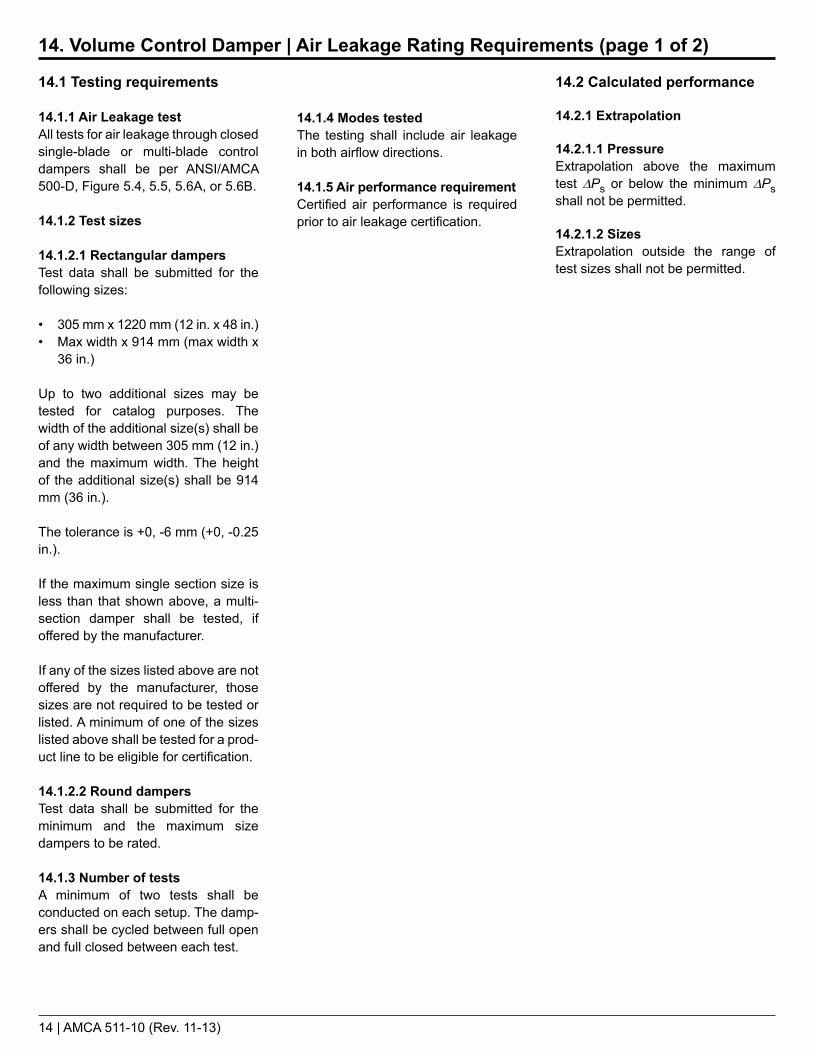
14.2 Calculated performance
14.2.1 Extrapolation
14.2.1.1 PressureExtrapolation above the maximum test DPs or below the minimum DPs shall not be permitted.
14.2.1.2 SizesExtrapolation outside the range of test sizes shall not be permitted.
14.1.4 Modes testedThe testing shall include air leakage in both airflow directions.
14.1.5 Air performance requirementCertified air performance is required prior to air leakage certification.
14.1 Testing requirements
14.1.1 Air Leakage testAll tests for air leakage through closed single-blade or multi-blade control dampers shall be per ANSI/AMCA 500-D, Figure 5.4, 5.5, 5.6A, or 5.6B.
14.1.2 Test sizes
14.1.2.1 Rectangular dampersTest data shall be submitted for the following sizes:
• 305 mm x 1220 mm (12 in. x 48 in.)• Max width x 914 mm (max width x
36 in.)
Up to two additional sizes may be tested for catalog purposes. The width of the additional size(s) shall be of any width between 305 mm (12 in.) and the maximum width. The height of the additional size(s) shall be 914 mm (36 in.).
The tolerance is +0, -6 mm (+0, -0.25 in.).
If the maximum single section size is less than that shown above, a multi-section damper shall be tested, if offered by the manufacturer.
If any of the sizes listed above are not offered by the manufacturer, those sizes are not required to be tested or listed. A minimum of one of the sizes listed above shall be tested for a prod-uct line to be eligible for certification.
14.1.2.2 Round dampersTest data shall be submitted for the minimum and the maximum size dampers to be rated.
14.1.3 Number of testsA minimum of two tests shall be conducted on each setup. The damp-ers shall be cycled between full open and full closed between each test.
14. Volume Control Damper | Air Leakage Rating Requirements (page 1 of 2)

AMCA 511-10 (Rev. 11-13) | 15
14.3.4.2 Round dampersThe rating shall show the maximum air leakage class from both sizes tested in both modes (pressure in direction of flow, and back pressure). See Table 3.
14.3.5 Operational statementPublished data shall state the following:“Air leakage is based on operation between 0 °C - 49 °C (32 °F - 120 °F)”
14.3.6 Air performance ratingsAir performance ratings in the full open position shall be published in accordance with Section 13.
When optional sizes are tested in addition to the two required sizes, the air leakage class shall be published as a function of the damper width. At each pressure to be cataloged, publish the air leakage class from the worse performing of the two dampers used to establish each damper width range.
See the example test results and corresponding published data in Annex C, Figure C.7b.
14.3 Published ratings
14.3.1 Air leakage performancePublished ratings of air leakage performance shall be a statement of the appropriate class at the following:
• A specified differential pressure• Standard air density• AMCA figure or figures to which air
leakage performance is tested
14.3.2 Torque statementThe following statement shall be included:
“Data are based on a torque of [#] N•m/m2 (in.-lb/ft2) applied to close and seat the damper during the test.”
Stated torque value, in N•m/m2 (in.-lb/ft2), shall be the maximum of the samples tested.
[Any number ending with a decimal greater than 0.02 shall be rounded to the next higher number, e.g., 6.12 N•m/m2 = 6.1 N•m/m2 and 6.13 N•m/m2 = 6.2 N•m/m2 (5.12 in.-lb/ft2 = 5.1 in.-lb/ft2 and 5.13 in. lb/ft2 = 5.2 in.*lb/ft2)]
14.3.3 Opening torqueA table showing the opening torque may be included on the same page, provided it is labeled as “opening torque.”
14.3.4 Air leakage class
14.3.4.1 Rectangular dampersWhen only the two required sizes are tested, publish the maximum air leak-age class from the worse performing size at each catalog pressure. The worse leakage performance shall be based on the test results in both modes (pressure in direction of flow and back pressure). See Table 3.
14. Volume Control Damper | Air Leakage Rating Requirements (page 2 of 2)
Maximum Allowable Leakage, L/s/m2
at 0.25 kPa[1] at 1.0 kPa[1] at x kPa[2]
15.2 N/A N/A20 41 2√x × 2051 102 2√x × 51203 406 2√x × 203
Class1A123
SI
Maximum Allowable Leakage, cfm/ft2
at 1 in. wg[1] at 4 in. wg[1] at x in. wg[2]
3 N/A N/A4 8 √x × 4
10 20 √x × 1040 80 √x × 40
Class1A123
I-P
Table 3Allowable Air Leakage to Achieve Classification
Notes:[1] Required pressures; shall be cataloged[2] Any other pressure may be cataloged using these formulas
16 | AMCA 511-10 (Rev. 11-13)
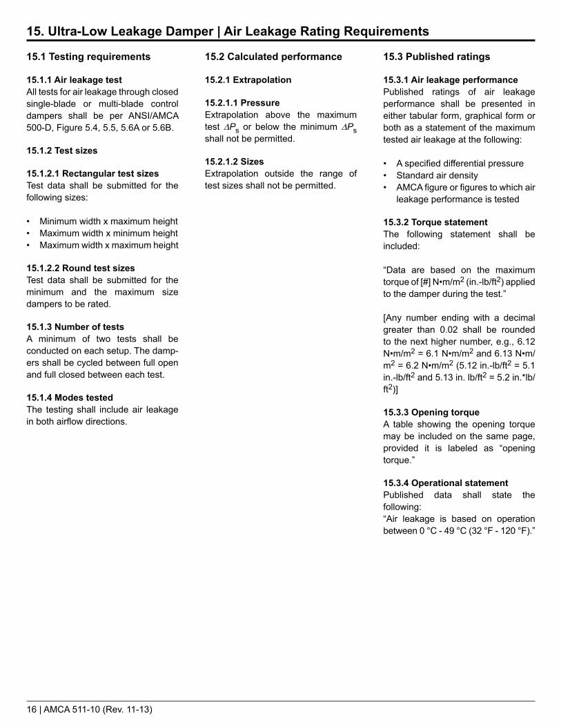
15.3 Published ratings
15.3.1 Air leakage performancePublished ratings of air leakage performance shall be presented in either tabular form, graphical form or both as a statement of the maximum tested air leakage at the following:
• A specified differential pressure• Standard air density• AMCA figure or figures to which air
leakage performance is tested
15.3.2 Torque statementThe following statement shall be included:
“Data are based on the maximum torque of [#] N•m/m2 (in.-lb/ft2) applied to the damper during the test.”
[Any number ending with a decimal greater than 0.02 shall be rounded to the next higher number, e.g., 6.12 N•m/m2 = 6.1 N•m/m2 and 6.13 N•m/m2 = 6.2 N•m/m2 (5.12 in.-lb/ft2 = 5.1 in.-lb/ft2 and 5.13 in. lb/ft2 = 5.2 in.*lb/ft2)]
15.3.3 Opening torqueA table showing the opening torque may be included on the same page, provided it is labeled as “opening torque.”
15.3.4 Operational statementPublished data shall state the following:“Air leakage is based on operation between 0 °C - 49 °C (32 °F - 120 °F).”
15.2 Calculated performance
15.2.1 Extrapolation
15.2.1.1 PressureExtrapolation above the maximum test DPs or below the minimum DPs shall not be permitted.
15.2.1.2 SizesExtrapolation outside the range of test sizes shall not be permitted.
15.1 Testing requirements
15.1.1 Air leakage testAll tests for air leakage through closed single-blade or multi-blade control dampers shall be per ANSI/AMCA 500-D, Figure 5.4, 5.5, 5.6A or 5.6B.
15.1.2 Test sizes
15.1.2.1 Rectangular test sizesTest data shall be submitted for the following sizes:
• Minimum width x maximum height• Maximum width x minimum height• Maximum width x maximum height
15.1.2.2 Round test sizesTest data shall be submitted for the minimum and the maximum size dampers to be rated.
15.1.3 Number of testsA minimum of two tests shall be conducted on each setup. The damp-ers shall be cycled between full open and full closed between each test.
15.1.4 Modes testedThe testing shall include air leakage in both airflow directions.
15. Ultra-Low Leakage Damper | Air Leakage Rating Requirements
AMCA 511-10 (Rev. 11-13) | 17
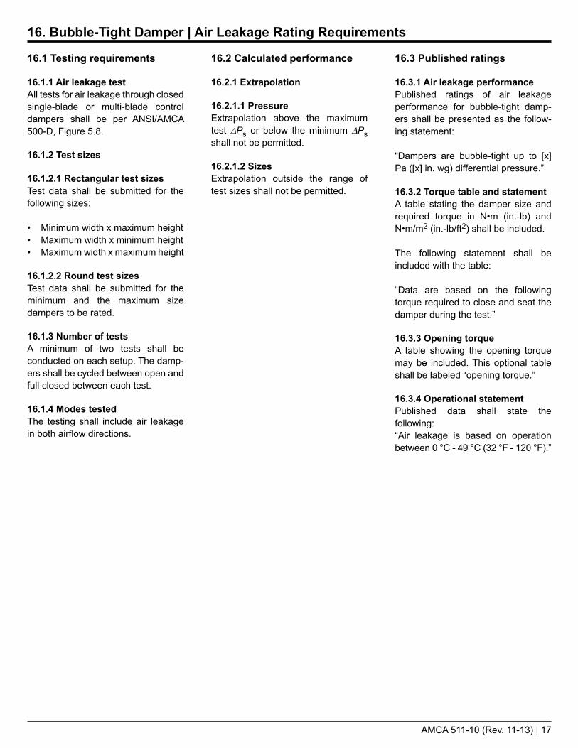
16.3 Published ratings
16.3.1 Air leakage performancePublished ratings of air leakage performance for bubble-tight damp-ers shall be presented as the follow-ing statement:
“Dampers are bubble-tight up to [x] Pa ([x] in. wg) differential pressure.”
16.3.2 Torque table and statementA table stating the damper size and required torque in N•m (in.-lb) and N•m/m2 (in.-lb/ft2) shall be included.
The following statement shall be included with the table:
“Data are based on the following torque required to close and seat the damper during the test.”
16.3.3 Opening torqueA table showing the opening torque may be included. This optional table shall be labeled “opening torque.”
16.3.4 Operational statementPublished data shall state the following:“Air leakage is based on operation between 0 °C - 49 °C (32 °F - 120 °F).”
16.2 Calculated performance
16.2.1 Extrapolation
16.2.1.1 PressureExtrapolation above the maximum test DPs or below the minimum DPs shall not be permitted.
16.2.1.2 SizesExtrapolation outside the range of test sizes shall not be permitted.
16.1 Testing requirements
16.1.1 Air leakage testAll tests for air leakage through closed single-blade or multi-blade control dampers shall be per ANSI/AMCA 500-D, Figure 5.8.
16.1.2 Test sizes
16.1.2.1 Rectangular test sizesTest data shall be submitted for the following sizes:
• Minimum width x maximum height• Maximum width x minimum height• Maximum width x maximum height
16.1.2.2 Round test sizesTest data shall be submitted for the minimum and the maximum size dampers to be rated.
16.1.3 Number of testsA minimum of two tests shall be conducted on each setup. The damp-ers shall be cycled between open and full closed between each test.
16.1.4 Modes testedThe testing shall include air leakage in both airflow directions.
16. Bubble-Tight Damper | Air Leakage Rating Requirements

18 | AMCA 511-10 (Rev. 11-13)
17.3 Published rating
17.3.1 Air leakage performancePublished rating of air leakage shall be a statement of the UL 555S published rating class.
17.3.2 Air leakage classPublished ratings shall show the maximum air leakage class in both airflow directions.
17.3.3 Figures to which testedPublished ratings shall state the AMCA figure or figures to which they are tested.
17.3.4 Air performance requirementAir performance ratings of damp-ers in the full open position shall be published in accordance with Section 13.3.
17.2 Calculated performance
17.2.1 Air leakageAir leakage performance shall meet the requirements of the UL leakage classification for the model tested.
17.1 Testing requirements
17.1.1 Test sampleDamper shall be a UL-classified damper as defined in Section 3.1.8.
17.1.2 Air leakage test
17.1.2.1 Cycling before air leakage testBefore the air leakage test, the damper shall be cycled open and closed. During this cycle, the UL test velocity corresponding to the highest velocity to which the damper is UL classified shall be applied across the open damper. The UL test DPs corre-sponding to the highest pressure to which the damper is UL classified to shall be applied across the closed damper.
17.1.2.2 Test figureAll testing for air leakage shall be per ANSI/AMCA 500-D, Figure 5.4, Figure 5.5 or Figure 5.9 at ambient temperatures.
17.1.2.3 Closing methodThe air leakage test shall be conducted with the appropriate springs, actuators or other closing devices, normally supplied with the UL-Classified damper, applying the closing torque or force.
17.1.2.4 Modes testedThe testing shall include air leakage in both airflow directions.
17.1.3 Check test sizes
17.1.3.1 Rectangular test sizesOne of the following sizes shall be tested:
• Minimum width x maximum height• Maximum width x minimum height• Maximum width x maximum height
17.1.3.2 Round test sizesEither the minimum or the maximum size damper to be rated shall be tested.
17. UL-Classified Damper | Air Leakage Rating Requirements

AMCA 511-10 (Rev. 11-13) | 19
18.3 Published rating
18.3.1 Air leakage performancePublished rating of air leakage perfor-mance shall be a statement of the maximum tested air leakage flow rate at a specified DPs at standard air density.
18.3.2 Test setupPublished data shall show the test figure and airflow direction used during testing.
18.3.3 Test sizePublished data shall show the test sample size.
18.3.4 Operational statementPublished data shall state:“Air leakage is based on operation between 0 °C - 49 °C (32 °F - 120 °F).”
18.3.5 Air performance requirementTo publish air leakage ratings, air performance ratings of the test sample defined in Section 18.1.2 only shall be tested and published in accordance with Section 13.
18.2 Calculated performance
18.2.1 Air leakageAir leakage performance at each DPs shall be the maximum L/s/m2 (cfm/ft2) of two tests conducted.
18.2.2 Extrapolation
18.2.2.1 PressureExtrapolation above the maximum test DPs or below the minimum DPs shall not be permitted.
18.2.2.2 Test sizeExtrapolation outside the test size shall not be permitted.
18.1 Testing requirements
18.1.1 Air leakage testAll testing for air leakage through mounted dampers shall be per ANSI/AMCA 500-D, Figure 5.4 or Figure 5.5. Dampers shall be mounted such that the airflow closes the blades.
18.1.2 Test sizes
18.1.2.1 Rectangular test sizeA 610 mm x 610 mm (24 in. x 24 in.) damper shall be tested. If the largest size damper produced is smaller than 610 mm x 610 mm (24 in. x 24 in.), the largest cataloged size shall be tested.
18.1.2.2 Round test sizeA 610 mm (24 in.) diameter damper shall be tested. If the largest size damper produced is smaller than 610 mm (24 in.), the largest cataloged size shall be tested.
18.1.3 CyclingPrior to testing for air leakage, the test sample shall be opened 15° and allowed to close under its own force with zero DPs across the damper.
18.1.4 Test pressureThe testing shall be conducted from the lowest rated differential pressure up to the highest.
18.1.5 Number of testsTwo tests shall be conducted on each sample. Each test shall be conducted over a range of pressures consisting of at least five points.
Between each test, the damper shall be opened 15° and allowed to close under its own force with zero DPs across the damper. If a motor is used, the damper shall be cycled from its full open to its full closed position between tests.
18. Backdraft Damper | Air Leakage Rating Requirements

20 | AMCA 511-10 (Rev. 11-13)
19.3 Published ratings
19.3.1 Air performancePublished ratings of air performance shall include the following for all required sizes:
• Maximum DPs at a specified airflow rate
• Data corrected to standard air density
• AMCA figure or figures to which air performance is tested, for all required sizes
• Minimum curb height, if applicable
19.3.2 PresentationRatings shall be published in tabular form, graphical form or both.
19.3.3 Rounding of dataPressure drop information shall be presented rounded to the nearest pascal, if using SI units in literature, or presented with a maximum of two digits after the decimal point, if using I-P units.
19.3.4 Screen/appurtenanceThe type of screen installed on the unit during the test shall be listed in the required appurtenance statement (see Section 5.3).
19.3.5 Mode testedPublished ratings shall indicate the mode tested (intake or relief).
19.3.6 SizesPublished ratings shall include a list of the tested size(s) as described in Section 19.1.3.1 or 19.1.3.2.
19.2 Calculated performance
19.2.1 Air performanceAir performance of any size gravity ventilator may be calculated from data of a tested size. The manufacturer is responsible for ensuring proper corrections are made to account for aspect ratio changes, changes in hood dimensions, etc., (see Figure 19.1, dimensions C, D and E; or, Figure 19.2, dimensions C and E).
19.2.2 ExtrapolationExtrapolation above the maximum and below the minimum test DPs shall not be permitted.
19.1 Testing requirements
19.1.1 Pressure drop testAll testing for pressure drop determina-tions of gravity ventilators shall be per ANSI/AMCA 500-L, Figure 5.4 or 5.5.
For Figure 5.4 testing, the outlet chamber shall have a cross-sectional area at least nine (instead of fifteen) times the throat area of the device being tested.
A test shall consist of five or more determinations taken at approxi-mately equal increments of airflow rate covering the range desired.
19.1.2 ScreensGravity ventilators shall be tested with screens installed.
19.1.3 Test (throat) sizes
19.1.3.1 RectangularThe following throat sizes (see Figure 19.1, dimensions A and B) shall be tested for rectangular gravity ventilators:
• 305 mm x 305 mm (12 in. x 12 in.)• 610 mm x 610 mm (24 in. x 24 in.)• 915 mm x 915 mm (36 in. x 36 in.)
If any of these sizes are not offered by the manufacturer, those sizes are not required to be tested or listed. A mini-mum of one of the listed sizes shall be tested to be eligible for licensing.
19.1.3.2 RoundThe following throat sizes (see Figure 19.2, dimension A) shall be tested for round gravity ventilators:
• Smallest• Largest• Midway between the largest and
smallest
If less than three sizes are offered by the manufacturer, test data shall be submitted for all sizes in order to be eligible for licensing.
19. Gravity Ventilator (Excluding Louver Penthouses) | Air Performance Rating Requirements

AMCA 511-10 (Rev. 11-13) | 21
A B
C x D
A x B
F
E
C D
E
E
F
C
A
Figure 19.1Gravity Ventilator with Rectangular and Square Hoods
Figure 19.2Gravity Ventilator with Round Hood

22 | AMCA 511-10 (Rev. 11-13)
20.3 Published ratings
20.3.1 Air leakage performancePublished rating of air leakage perfor-mance shall be a statement of the maximum tested air leakage flow rate for each gauge at 3.75 kPa (15 in. wg) DPs in m3/hr per 9.29 m2 (cfm per 100 ft2) of duct wall surface area at stan-dard air density.
20.3.2 Test sample informationPublished data shall include the following test sample information:
• Length• Gauge• Diameter
20.3.3 Certified gaugesAll gauges of spiral duct published in a catalog shall be certified.
20.2 Calculated performance
20.2.1 Data correctionAir leakage performance shall be corrected from actual conditions to standard conditions using the equa-tions shown in ANSI/ASHRAE/SMACNA Standard 126-2008, Section 7.4.
20.2.2 Data conversionThe calculated air leakage perfor-mance in m3/hr (cfm) shall be converted to m3/hr per 9.29 m2 (cfm per 100 ft2) of duct wall surface.
20.1 Testing requirements
20.1.1 Air leakage testAll spiral duct air leakage testing shall be conducted in accordance with ANSI/ASHRAE/SMACNA Standard 126-2008, Section 7.
20.1.2 Bubble testA bubble test shall be conducted in accordance with ANSI/AMCA 500-D prior to the air leakage test to ensure there is no endcap leakage.
20.1.3 Test pressureTesting shall be performed at 1.5 times the normal maximum design pressure of 2.5 kPa (10 in. wg).
20.1.4 Test sampleThe test sample shall be a 600 mm (24 in.) diameter by 3000 mm (120 in.) long section of spiral duct. The ends shall be capped and sealed by the manufacturer and one endcap shall also contain two DN10 (3/8 in.) pipe size barb fittings.
Testing shall include ducts of the following gauges:
28, 26, 24, 22, 20, 18, 16, 14.
If the manufacturer does not produce all of the required gauges, testing shall include all gauges that a manu-facturer produces.
20. Round Spiral Duct | Air Leakage Rating Requirements

AMCA 511-10 (Rev. 11-13) | 23
21.3 Published ratings
21.3.1 Required dataRatings shall include the following:• Efficiency performance, stated
as a percentage efficiency as compared to the reference damper
• Test sample size• Test figure
21.3.2 Torque statementPublished ratings shall include a statement of the torque required to hold the louver/damper in the closed position.
21.2 Calculated performance
The performance shall be rated as a percentage increase in efficiency over the reference 3-V-groove damper.
21.1 Testing requirements
21.1.1 Thermal transmittance testAll tests for thermal transmittance shall be conducted in accordance with AMCA Standard 500-D.
21.1.2 Test sampleTest data shall be submitted for a 915 mm x 915 mm (36 in. x 36 in.) louver/damper.
21.1.3 Test temperatureTesting shall be conducted such that the thermal chamber temperature is 16.7 ºC (30 ºF) greater than the ambi-ent lab temperature.
21.1.4 Test pressureTesting shall be conducted with the test chamber pressurized to 0.25 kPa (1 in. wg).
21.1.5 Reference damperThe reference damper shall be a 3-V groove damper with blade and jamb seals that requires 760 watts to main-tain the 16.7 ºC (30 ºF) test tempera-ture differential.
21. Louver/Damper | Energy Efficiency Rating Requirements
24 | AMCA 511-10 (Rev. 11-13)
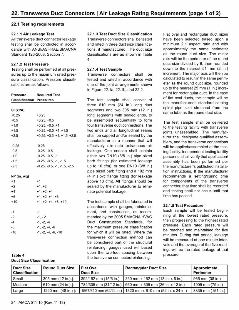
Flat oval and rectangular duct sizes have been selected based upon a minimum 2:1 aspect ratio and with approximately the same perimeter as the round duct size. The minor axis will be the perimeter of the round duct size divided by 6, then rounded down to the nearest 51 mm (2 in.) increment. The major axis will then be calculated to result in the same perim-eter as the round duct size, rounded up to the nearest 25 mm (1 in.) incre-ment for rectangular duct. In the case of flat oval ducts, the sample will be the manufacturer’s standard catalog spiral pipe size stretched from the same tube as the round duct size.
The test sample shall be delivered to the testing facility with transverse joints unassembled. The manufac-turer shall designate qualified assem-blers, and the transverse connections will be applied/assembled at the test-ing facility. Independent testing facility personnel shall verify that application/assembly has been performed per the manufacturer’s published installa-tion instructions. If the manufacturer recommends a setting/curing time for components of the transverse connector, that time shall be recorded and testing shall not occur until that time has passed.
22.1.5 Test ProcedureEach sample will be tested begin-ning at the lowest rated pressure, then progressing to the highest rated pressure. Each rated pressure will be reached and maintained for five minutes. During that period, leakage will be measured at one minute inter-vals and the average of the five read-ings will be the rated leakage at that pressure.
22.1.3 Test Duct Size ClassificationTransverse connectors shall be tested and rated in three duct size classifica-tions, if manufactured. The duct size classifications are as shown in Table 4.
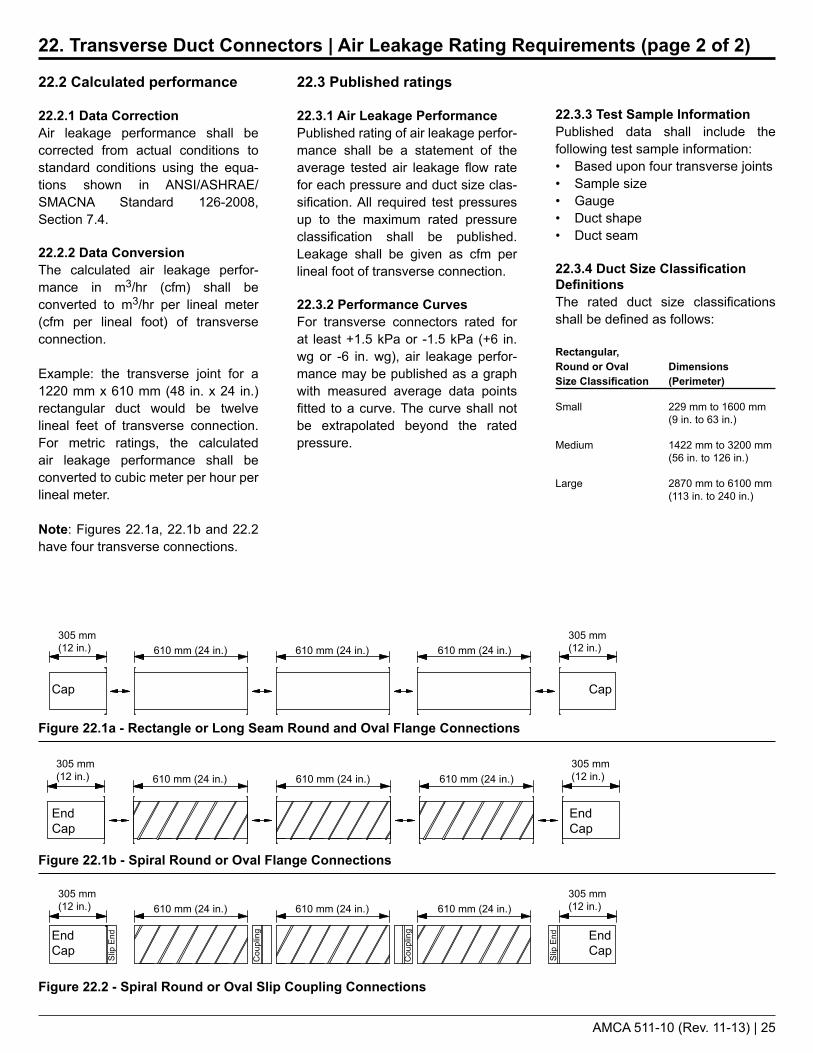
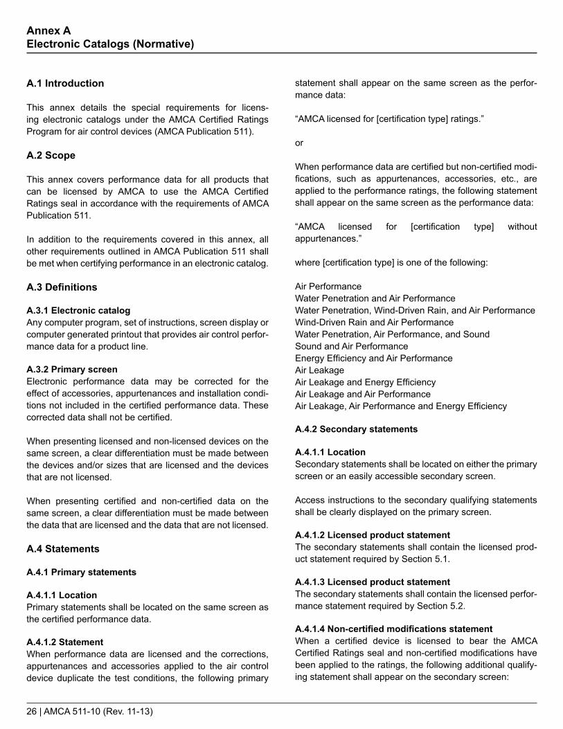
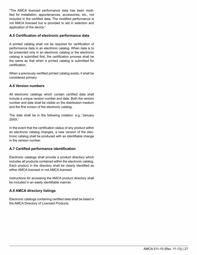
22.1.4 Test SampleTransverse connectors shall be tested and rated in accordance with one of the joint arrangements shown in Figure 22.1a, 22.1b, and 22.2.
The test sample shall consist of three 610 mm (24 in.) long duct segments and two 305 mm (12 in.) long segments with sealed ends, to be assembled sequentially to form four transverse duct connections. The two ends and all longitudinal seams shall be capped and/or sealed by the manufacturer in a manner that will effectively eliminate extraneous air leakage. One endcap shall contain either two DN10 (3/8 in.) pipe sized barb fittings (for estimated leakage up to 10 cfm), or one DN10 (3/8 in.) pipe sized barb fitting and a 102 mm (4 in.) pvc flange fitting (for leakage above 10 cfm). All fittings should be sealed by the manufacturer to elimi-nate potential leakage.
The test sample shall be fabricated in accordance with gauges, reinforce-ment, and construction, as recom-mended by the 2005 SMACNA HVAC Duct Construction Standards, for the maximum pressure classification for which it will be rated. Where the transverse connection method can be considered part of the structural reinforcing, gauges used will based upon the two-foot spacing between the transverse connector/reinforcing.
22.1 Testing requirements
22.1.1 Air Leakage TestAll transverse duct connector leakage testing shall be conducted in accor-dance with ANSI/ASHRAE/SMACNA Standard 126-2008, Section 7.
22.1.2 Test PressureTesting shall be performed at all pres-sures up to the maximum rated pres-sure classification. Pressure classifi-cations are as follows:
Pressure Required TestClassification Pressures
SI (kPA)+0.25 +0.25+0.5 +0.25, +0.5+1.0 +0.25, +0.5, +1+1.5 +0.25, +0.5, +1, +1.5+2.5 +0.25, +0.5, +1, +1.5, +2.5
-0.25 -0.25-0.5 -0.25, -0.5-1.0 -0.25, -0.5, -1-1.5 -0.25, -0.5, -1, -1.5-2.5 -0.25, -0.5, -1, -1.5, -2.5
I-P (in. wg)+1 +1+2 +1, +2+4 +1, +2, +4+6 +1, +2, +4, +6+10 +1, +2, +4, +6, +10
-1 -1-2 -1, - 2-4 -1, -2, -4-6 -1, -2, -4, -6-10 -1, -2, -4, -6, -10
22. Transverse Duct Connectors | Air Leakage Rating Requirements (page 1 of 2)
Duct Size Classification
Round Duct Size Flat Oval Duct Size
Rectangular Duct Size Approximate Perimeter
Small 305 mm (12 in.) φ 392/152 mm (15/6 in.) 330 mm x 152 mm (13 in. x 6 in.) 965 mm (38 in.)Medium 610 mm (24 in.) φ 784/305 mm (31/12 in.) 660 mm x 305 mm (26 in. x 12 in.) 1905 mm (75 in.)Large 1220 mm (48 in.) φ 1567/610 mm (62/24 in.) 1320 mm x 610 mm (52 in. x 24 in.) 3835 mm (151 in.)
Table 4Duct Size Classification
AMCA 511-10 (Rev. 11-13) | 25
22. Transverse Duct Connectors | Air Leakage Rating Requirements (page 2 of 2)
22.3.3 Test Sample InformationPublished data shall include the following test sample information:• Based upon four transverse joints• Sample size• Gauge• Duct shape• Duct seam
22.3.4 Duct Size Classification DefinitionsThe rated duct size classifications shall be defined as follows:
Rectangular,Round or Oval DimensionsSize Classification (Perimeter)
Small 229 mm to 1600 mm (9 in. to 63 in.)
Medium 1422 mm to 3200 mm (56 in. to 126 in.)
Large 2870 mm to 6100 mm (113 in. to 240 in.)
22.3 Published ratings
22.3.1 Air Leakage PerformancePublished rating of air leakage perfor-mance shall be a statement of the average tested air leakage flow rate for each pressure and duct size clas-sification. All required test pressures up to the maximum rated pressure classification shall be published. Leakage shall be given as cfm per lineal foot of transverse connection.
22.3.2 Performance CurvesFor transverse connectors rated for at least +1.5 kPa or -1.5 kPa (+6 in. wg or -6 in. wg), air leakage perfor-mance may be published as a graph with measured average data points fitted to a curve. The curve shall not be extrapolated beyond the rated pressure.
22.2 Calculated performance
22.2.1 Data CorrectionAir leakage performance shall be corrected from actual conditions to standard conditions using the equa-tions shown in ANSI/ASHRAE/SMACNA Standard 126-2008, Section 7.4.
22.2.2 Data ConversionThe calculated air leakage perfor-mance in m3/hr (cfm) shall be converted to m3/hr per lineal meter (cfm per lineal foot) of transverse connection.
Example: the transverse joint for a 1220 mm x 610 mm (48 in. x 24 in.) rectangular duct would be twelve lineal feet of transverse connection. For metric ratings, the calculated air leakage performance shall be converted to cubic meter per hour per lineal meter.
Note: Figures 22.1a, 22.1b and 22.2 have four transverse connections.
Figure 22.1a - Rectangle or Long Seam Round and Oval Flange Connections
Figure 22.2 - Spiral Round or Oval Slip Coupling Connections
Figure 22.1b - Spiral Round or Oval Flange Connections
Cap Cap
610 mm (24 in.)305 mm (12 in.)
305 mm (12 in.)610 mm (24 in.) 610 mm (24 in.)
End Cap
EndCap
610 mm (24 in.)305 mm (12 in.)
305 mm (12 in.)610 mm (24 in.) 610 mm (24 in.)
Cou
plin
g
Cou
plin
g
Slip
End
Slip
End
End Cap
EndCap
610 mm (24 in.)305 mm (12 in.)
305 mm (12 in.)610 mm (24 in.) 610 mm (24 in.)
26 | AMCA 511-10 (Rev. 11-13)
Annex A Electronic Catalogs (Normative)
A.1 Introduction
This annex details the special requirements for licens-ing electronic catalogs under the AMCA Certified Ratings Program for air control devices (AMCA Publication 511).
A.2 Scope
This annex covers performance data for all products that can be licensed by AMCA to use the AMCA Certified Ratings seal in accordance with the requirements of AMCA Publication 511.
In addition to the requirements covered in this annex, all other requirements outlined in AMCA Publication 511 shall be met when certifying performance in an electronic catalog.
A.3 Definitions
A.3.1 Electronic catalogAny computer program, set of instructions, screen display or computer generated printout that provides air control perfor-mance data for a product line.
A.3.2 Primary screenElectronic performance data may be corrected for the effect of accessories, appurtenances and installation condi-tions not included in the certified performance data. These corrected data shall not be certified.
When presenting licensed and non-licensed devices on the same screen, a clear differentiation must be made between the devices and/or sizes that are licensed and the devices that are not licensed.
When presenting certified and non-certified data on the same screen, a clear differentiation must be made between the data that are licensed and the data that are not licensed.
A.4 Statements
A.4.1 Primary statements
A.4.1.1 LocationPrimary statements shall be located on the same screen as the certified performance data.
A.4.1.2 StatementWhen performance data are licensed and the corrections, appurtenances and accessories applied to the air control device duplicate the test conditions, the following primary
statement shall appear on the same screen as the perfor-mance data:
“AMCA licensed for [certification type] ratings.”
or
When performance data are certified but non-certified modi-fications, such as appurtenances, accessories, etc., are applied to the performance ratings, the following statement shall appear on the same screen as the performance data:
“AMCA licensed for [certification type] without appurtenances.”
where [certification type] is one of the following:
Air PerformanceWater Penetration and Air PerformanceWater Penetration, Wind-Driven Rain, and Air PerformanceWind-Driven Rain and Air PerformanceWater Penetration, Air Performance, and SoundSound and Air PerformanceEnergy Efficiency and Air PerformanceAir LeakageAir Leakage and Energy EfficiencyAir Leakage and Air PerformanceAir Leakage, Air Performance and Energy Efficiency
A.4.2 Secondary statements
A.4.1.1 LocationSecondary statements shall be located on either the primary screen or an easily accessible secondary screen.
Access instructions to the secondary qualifying statements shall be clearly displayed on the primary screen.
A.4.1.2 Licensed product statementThe secondary statements shall contain the licensed prod-uct statement required by Section 5.1.
A.4.1.3 Licensed product statementThe secondary statements shall contain the licensed perfor-mance statement required by Section 5.2.
A.4.1.4 Non-certified modifications statementWhen a certified device is licensed to bear the AMCA Certified Ratings seal and non-certified modifications have been applied to the ratings, the following additional qualify-ing statement shall appear on the secondary screen:
AMCA 511-10 (Rev. 11-13) | 27
“The AMCA licensed performance data has been modi-fied for installation, appurtenances, accessories, etc., not included in the certified data. The modified performance is not AMCA licensed but is provided to aid in selection and application of the device.“
A.5 Certification of electronic performance data
A printed catalog shall not be required for certification of performance data in an electronic catalog. When data is to be presented only in an electronic catalog or the electronic catalog is submitted first, the certification process shall be the same as that when a printed catalog is submitted for certification.
When a previously certified printed catalog exists, it shall be considered primary.
A.6 Version numbers
All electronic catalogs which contain certified data shall include a unique version number and date. Both the version number and date shall be visible on the distribution medium and the first screen of the electronic catalog.
The date shall be in the following notation: e.g.,“January 20XX.”
In the event that the certification status of any product within an electronic catalog changes, a new version of the elec-tronic catalog shall be produced with an identifiable change in the version number.
A.7 Certified performance identification
Electronic catalogs shall provide a product directory which includes all products contained within the electronic catalog. Each product in the directory shall be clearly identified as either AMCA licensed or not AMCA licensed.
Instructions for accessing the AMCA product directory shall be included in an easily identifiable manner.
A.8 AMCA directory listings
Electronic catalogs containing certified data shall be listed in the AMCA Directory of Licensed Products.

(continued →)
28 | AMCA 511-10 (Rev. 11-13)
Annex B Measurements (Normative)
B.1 Calculating louver free area
BB
L W L W L W
CCH H H
AA
C1 = B
A
B
TYPE 3 SECTIONS(Horizontal blades)
B
L H
CW
A
B
TYPE 4 SECTIONS(Vertical blades)
TYPE 1 SECTIONS(Horizontal blades)
TYPE 2 SECTIONS(Horizontal blades)
C
Figure B.1Typical Louver and Frame Cross Section Showing Minimum Distance Formula

Figure B.1 Formulas
AMCA 511-10 (Rev. 11-13) | 29
Horizontal blade louvers
A = Minimum distance between the head and top blade* Note: Where the top blade dimension C is less than A, use the value for CB = Minimum distance between the sill and bottom blade*C = Minimum distance between adjacent blades Note: In louver type 2, C may not be equal to C1*N = Number of C openings in the louverL = Minimum distance between louver jambsW = Actual louver widthH = Actual louver height * The A, B & C spaces shall be measured within 1 in. from each jamb and averaged
Vertical blade louvers
A* = Minimum distance between the left jamb and left blade* Note: Where the left blade dimension C is less than A, use the value for CB* = Minimum distance between the right jamb and right blade*C* = Minimum distance between adjacent blades*N = Number of C openings in the louverL = Minimum distance between louver head and sillW = Actual louver widthH = Actual louver height * The A, B & C spaces shall be measured within 1 in. from each blade end and averaged
Note:When measuring two louvers placed back to back, the free area for the combined louvers shall be determined as the smaller of the two free areas.
FreeArea L A B N C= + + ×[ ( )] Percent FreeArea L A B N CW H
=+ + ×
×[ ( )]100

30 | AMCA 511-10 (Rev. 11-13)
BB
L W L W L W
CCH H H
AA
C1 = B
A
B
TYPE 3 SECTIONS(Horizontal blades)
B
L H
CW
A
B
TYPE 4 SECTIONS(Vertical blades)
TYPE 1 SECTIONS(Horizontal blades)
TYPE 2 SECTIONS(Horizontal blades)
C
Figure B.2Calculating Damper Area
B.2 Calculating damper area
The results of an air leakage test for dampers shall be presented as a statement of pressure differential (Pa or in. wg) across the device versus the flow rate per face area of damper (L/s/m2 or cfm/ft2) at standard air density. The face area is determined by the installation method as shown in the sketches below.

Annex
AMCA 511-10 (Rev. 11-13) | 31
This informative annex is intended to be an additional resource for the development of air control catalogs.
It is not intended to be used as a replacement for the detailed requirements listed in Sections 8 through 23.
Annex C Developing Air Control Product Catalogs (Informative)
Device — Certification TypeRatingRequirements
ExampleTest Report
ExampleCatalog
Louver — Air Performance Section 8 Page 32 Page 33
Louver — Wind-Driven Rain Section 9 Page 34 Page 35
Louver — Water Penetration Section 10 Page 36 Page 37
Acoustical Louver — Sound Performance Section 11 Page 38 Page 39
Adjustable Louver — Air Leakage Section 12 Page 40 Page 41
Damper — Air Performance Section 13 Page 42 Page 43
Volume Control Damper — Air Leakage Section 14 Page 44 Pages 45-46
Ultra-Low-Leakage Damper — Air Leakage Section 15 Page 47 Page 48
Bubble-Tight Damper — Air Leakage Section 16 Page 49 Page 50
Backdraft Damper — Air Leakage Section 18 Page 51 Page 52
Gravity Ventilator — Air Performance Section 19 Page 53 Page 54
Round Spiral Duct — Air Leakage Section 20 Page 55 Page 56

32 | AMCA 511-10 (Rev. 11-13)
C.1 Louver Air Performance Test Report and Catalog Example
Figure C.1aExample Louver Air Performance Test Report
Air Movement and Control Association International, Inc.30 West University Drive, Arlington Heights, Illinois 60004-1893, U.S.A.
Test Number : 12345-E1 Test Type : ContractClient : ABC Test Figure : 5.5-6.5
: rebmahC : etaD LargePersonnel : John Smith Nozzle Comb. : 14
Witness(es) : None
Manufacturer : ABC Louver Type : AcousticTrade Name : AL123 Blade Orientation : Horizontal
Model : AL123 Blade Action : Size : 48x48x6 Blade Position :
Core Area (sq.ft.) : 13.44 Flow Direction : ExhaustFree Area (sq.ft.) : 4.69 Blade Type : Fixed
Appurtenances : None
Remarks :
Recorded Data : Det. p br t b p bc t do t wo t d5 P S8 t d8 ∆P n
1 29.380 76.4 29.244 75.7 56.7 81.2 0.610 79.8 4.7002 29.380 76.4 29.244 75.7 56.7 81.2 0.390 79.8 3.0003 29.380 76.4 29.244 75.7 56.7 81.2 0.240 79.8 1.8004 29.380 76.4 29.244 75.7 56.7 81.2 0.110 79.8 0.8005 29.380 76.4 29.244 75.7 56.7 81.2 0.040 79.8 0.305
Test Results at Standard Air : Det. ∆P DS Q DS V Free Area C D C D Class
1 0.638 9559.1 2038.2 0.22 32 0.408 7633.1 1627.5 0.22 33 0.251 5907.1 1259.5 0.22 34 0.115 3930.1 838.0 0.22 35 0.042 2418.9 515.7 0.22 3
January 1, 2009
AMCA Standard 500-L-99 Air Performance - Pressure Drop Test
These data are not certified by AMCA

Catalog ID: AL123 April, 2011
AMCA 511-10 (Rev. 11-13) | 33
Note:This sample catalog contains only the items required for certification. Additional information, such as construction details, instal-lation information, pictures, etc., may be added as necessary.
Figure C.1bExample Louver Air Performance Catalog
Company ABC certifies that the AL123 shown hereon is licensed to bear the AMCA Seal. The rat-ings shown are based on tests and procedures performed in ac-cordance with AMCA Publication 511 and comply with the require-ments of the AMCA Certified Ratings Program.
The AMCA Certified Ratings Seal applies to Air Performance ratings.
Test InformationTested in accordance with ANSI/AMCA 500-L, Figure 5.5Test sample size is 1220 mm x 1220 mm (48 in. x 48 in.)Air performance data are based on intake performance
Free Area Velocity (FPM x 100)
∆Ps
Pres
sure
Dro
p (in
. wg)
1 10 20 300.01
0.1
1.0
8 12 18 24 30 36 42 48 54 60 66 72 78 84 90 9612 0.24 0.40 0.65 0.90 1.14 1.39 1.63 1.88 2.13 2.37 2.62 2.86 3.11 3.36 3.60 3.8518 0.33 0.55 0.89 1.23 1.57 1.90 2.24 2.58 2.92 3.26 3.59 3.93 4.27 4.61 4.94 5.2824 0.47 0.80 1.28 1.77 2.25 2.74 3.22 3.71 4.19 4.68 5.16 5.65 6.13 6.62 7.10 7.5930 0.61 1.03 1.66 2.28 2.91 3.54 4.17 4.79 5.42 6.05 6.68 7.30 7.93 8.56 9.19 9.8136 0.78 1.32 2.12 2.92 3.72 4.53 5.33 6.13 6.93 7.74 8.54 9.34 10.14 10.94 11.75 12.5542 0.92 1.56 2.51 3.46 4.41 5.36 6.31 7.26 8.21 9.16 10.11 11.06 12.01 12.96 13.91 14.8648 1.06 1.79 2.88 3.98 5.07 6.16 7.25 8.34 9.44 10.53 11.62 12.71 13.80 14.90 15.99 17.0854 1.23 2.08 3.35 4.61 5.88 7.15 8.41 9.68 10.95 12.21 13.48 14.75 16.02 17.28 18.55 19.8260 1.38 2.32 3.73 5.15 6.56 7.98 9.39 10.81 12.22 13.64 15.05 16.46 17.88 19.29 20.71 22.1266 1.52 2.55 4.11 5.67 7.22 8.78 10.34 11.89 13.45 15.01 16.56 18.12 19.68 21.23 22.79 24.3572 1.69 2.84 4.57 6.30 8.04 9.77 11.50 13.23 14.96 16.69 18.43 20.16 21.89 23.62 25.35 27.0878 1.83 3.08 4.96 6.84 8.72 10.60 12.48 14.36 16.24 18.12 19.99 21.87 23.75 25.63 27.51 29.3984 1.97 3.32 5.34 7.36 9.38 11.40 13.42 15.44 17.47 19.49 21.51 23.53 25.55 27.57 29.59 31.6290 2.14 3.60 5.80 7.99 10.19 12.39 14.58 16.78 18.98 21.17 23.37 25.57 27.76 29.96 32.16 34.3596 2.28 3.84 6.19 8.53 10.88 13.22 15.56 17.91 20.25 22.59 24.94 27.28 29.63 31.97 34.31 36.66
AL123 FREE AREA (SQ. FT.)
Hei
ght -
Inch
es
Width - Inches
Company ABCModel AL123

34 | AMCA 511-10 (Rev. 11-13)
C.2 Louver Wind-Driven Rain Test Report and Catalog Example
Figure C.2aExample Louver Wind-Driven Test Report - 3 in./hr Rainfall Rate, 29 mph Wind Velocity
AMCA Test Number : Louver Manufacturer : Client : Model :
84: ).ni( htdiW lanimoN : esopruP 84: ).ni( thgieH lanimoN : tseT etalP .laC fo )s(etaD
: ).ni( htdiW eroC : tseT revuoL fo )s(etaD : ).ni( thgieH eroC : lennosreP tseT
Witness(es) :
Simulated Weather Condition Rainfall rate (in. per hour) : 3 Wind Velocity (mph) : 29
ABC WDRL123
Air Movement and Control Association International, Inc.30 West University Drive, Arlington Heights, Illinois 60004-1893 U.S.A.
12345-WD1 ABC
Wind Driven Rain Water Penetration Test ReportConducted according to AMCA Standard 500-L-99, Figure 5.11
Contract Test
39.375
1-3-0639.375
John SmithNone
1-01-09
Actual Louver DataBarometric Ambient Dry- Ambient Wet- Differential Ventilation Supply Penetrated Spray Nozzle
Determination Pressure Bulb Temp. Bulb Temp. Pressure Airflow Water Flow Water Flow Settingp b t do t wo ∆P q v q s q d
(in Hg) (°F) (°F) (in wg) (cfm) (gph) (gph) (%)
1 29.59 66.1 60.7 0.000 0 50.18 0.074 15.52 29.59 64.6 60.0 0.059 1143 44.95 0.129 14.03 29.59 67.0 61.3 0.245 2342 44.25 0.196 13.64 29.59 64.9 59.9 0.424 3079 44.05 0.364 13.25 29.59 65.5 60.2 0.769 4156 41.23 0.647 12.86 29.59 66.8 60.0 1.281 5377 39.41 1.230 12.37 29.59 66.8 60.0 1.763 6313 37.65 1.685 11.98 29.59 70.6 58.8 2.394 7385 36.78 2.797 11.59 29.59 71.5 60.2 2.937 8193 37.10 3.393 11.2
10 29.59 71.9 60.8 3.683 9184 36.15 3.969 10.911 29.59 71.9 60.6 4.928 10631 35.32 5.339 10.7
Corrected DataVelocity Core Velocity Specified Nominal Corrected Water WaterThrough Through Rainfall Supply Flow Penetrated Penetration Penetration
noitacifissalCssenevitceffEwolF retaWetaRrevuoL etalP .laCnoitanimreteDv co v c q w q snom q dcor E
(fpm) (fpm) (gal/hr) (gal/hr) (gal/hr) (%)
1 0 0 20.135 45.955 0.0678 99.7 A2 132 106 20.135 43.374 0.1245 99.4 A3 197 218 20.135 42.210 0.1870 99.1 A4 287 286 20.135 40.926 0.3382 98.3 B5 380 386 20.135 39.383 0.6180 96.9 B6 472 499 20.135 39.147 1.2218 93.9 C7 587 586 20.135 37.797 1.6916 91.6 C8 680 686 20.135 36.560 2.7802 86.2 C9 780 761 20.135 34.432 3.1490 84.4 C
10 865 853 20.135 33.848 3.7163 81.5 C11 991 987 20.135 33.069 4.9987 75.2 D
These data are not certified by AMCA.

Catalog ID: WDRL123 April, 2011
AMCA 511-10 (Rev. 11-13) | 35
Company ABC certifies that the WDRL123 shown hereon is licensed to bear the AMCA Seal. The ratings shown are based on tests and procedures performed in accor-dance with AMCA Publication 511 and comply with the requirements of the AMCA Certified Ratings Program.
The AMCA Certified Ratings Seal applies to Wind-Driven Rain ratings.
Company ABCModel WDRL123
8 12 18 24 30 36 42 48 54 60 66 72 78 84 90 9612 0.24 0.40 0.65 0.90 1.14 1.39 1.63 1.88 2.13 2.37 2.62 2.86 3.11 3.36 3.60 3.8518 0.33 0.55 0.89 1.23 1.57 1.90 2.24 2.58 2.92 3.26 3.59 3.93 4.27 4.61 4.94 5.2824 0.47 0.80 1.28 1.77 2.25 2.74 3.22 3.71 4.19 4.68 5.16 5.65 6.13 6.62 7.10 7.5930 0.61 1.03 1.66 2.28 2.91 3.54 4.17 4.79 5.42 6.05 6.68 7.30 7.93 8.56 9.19 9.8136 0.78 1.32 2.12 2.92 3.72 4.53 5.33 6.13 6.93 7.74 8.54 9.34 10.14 10.94 11.75 12.5542 0.92 1.56 2.51 3.46 4.41 5.36 6.31 7.26 8.21 9.16 10.11 11.06 12.01 12.96 13.91 14.8648 1.06 1.79 2.88 3.98 5.07 6.16 7.25 8.34 9.44 10.53 11.62 12.71 13.80 14.90 15.99 17.0854 1.23 2.08 3.35 4.61 5.88 7.15 8.41 9.68 10.95 12.21 13.48 14.75 16.02 17.28 18.55 19.8260 1.38 2.32 3.73 5.15 6.56 7.98 9.39 10.81 12.22 13.64 15.05 16.46 17.88 19.29 20.71 22.1266 1.52 2.55 4.11 5.67 7.22 8.78 10.34 11.89 13.45 15.01 16.56 18.12 19.68 21.23 22.79 24.3572 1.69 2.84 4.57 6.30 8.04 9.77 11.50 13.23 14.96 16.69 18.43 20.16 21.89 23.62 25.35 27.0878 1.83 3.08 4.96 6.84 8.72 10.60 12.48 14.36 16.24 18.12 19.99 21.87 23.75 25.63 27.51 29.3984 1.97 3.32 5.34 7.36 9.38 11.40 13.42 15.44 17.47 19.49 21.51 23.53 25.55 27.57 29.59 31.6290 2.14 3.60 5.80 7.99 10.19 12.39 14.58 16.78 18.98 21.17 23.37 25.57 27.76 29.96 32.16 34.3596 2.28 3.84 6.19 8.53 10.88 13.22 15.56 17.91 20.25 22.59 24.94 27.28 29.63 31.97 34.31 36.66
AL123 FREE AREA (SQ. FT.)
Hei
ght -
Inch
es
Width - Inches
Note:This sample catalog contains only the items required for certification. Additional information, such as construction details, instal-lation information, pictures, etc., may be added as necessary.
Figure C.2bExample Louver Wind-Driven Rain Catalog
Core Velocity (fpm) 0 106 218 286 386 499 586 686 761 853 987
Effectiveness (%) 99.7 99.4 99.1 98.3 96.9 93.9 91.6 86.2 84.4 81.5 75.2
Penetration Class A A A B B C C C C C D
Core Velocity (fpm) 0 128 214 300 401 498 586 667 772 861 973
Effectiveness (%) 98.5 98.4 98.3 98.7 96.9 96.4 95.5 93.6 93.3 88.2 80.1
Penetration Class B B B B B B B C C C C
Rainfall Rate: 3 in./hrWind Velocity: 29 mph
Rainfall Rate: 8 in./hrWind Velocity: 50 mph
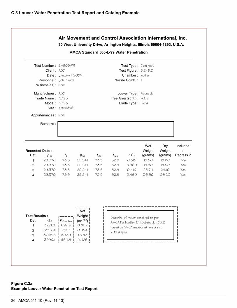
36 | AMCA 511-10 (Rev. 11-13)
C.3 Louver Water Penetration Test Report and Catalog Example
Figure C.3aExample Louver Water Penetration Test Report
Air Movement and Control Association International, Inc.30 West University Drive, Arlington Heights, Illinois 60004-1893, U.S.A.
Test Number : 24905-W1 Test Type : ContractClient : ABC Test Figure : 5.6-6.3
: rebmahC : etaD WaterPersonnel : John Smith Nozzle Comb. : 1
Witness(es) : None
Manufacturer : ABC Louver Type : AcousticTrade Name : AL123 Free Area (sq.ft.) : 4.69
Model : AL123 Blade Type : FixedSize : 48x48x6
Appurtenances : None
Remarks :
Wet Dry IncludedRecorded Data : Weight Weight in
Det. p br t b p bc t do t w o ∆P n (grams) (grams) Regress.?1 29.370 73.5 29.241 73.5 52.8 0.310 19.00 18.80 Yes2 29.370 73.5 29.241 73.5 52.8 0.360 18.50 18.00 Yes3 29.370 73.5 29.241 73.5 52.8 0.410 25.70 24.10 Yes4 29.370 73.5 29.241 73.5 52.8 0.460 36.50 33.20 Yes
NetTest Results : Weight
Det. Q S V Free Area (oz./ft2)1 3271.8 697.6 0.0022 3527.4 752.1 0.0043 3765.8 802.9 0.0124 3990.1 850.8 0.025
-999.0 ######-999.0 ######-999.0 ######-999.0 ######-999.0 ######-999.0 ######
January 1, 2009
AMCA Standard 500-L-99 Water Penetration
Beginning of water penetration perAMCA Publication 511 Subsection C3.2
799.4 fpmbased on AMCA measured free area :

AMCA 511-10 (Rev. 11-13) | 37
Company ABC certifies that the AL123 shown hereon is licensed to bear the AMCA Seal. The ratings shown are based on tests and procedures performed in accordance with AMCA Publi-cation 511 and comply with the requirements of the AMCA Certified Ratings Program.
The AMCA Certified Ratings Seal applies to Air Performance and Water Penetration ratings.
The beginning point of water penetration is 799.4 fpm.
Test InformationTested in accordance with ANSI/AMCA 500-L, Figure 5.5Test sample size is 1220 mm x 1220 mm (48 in. x 48 in.)Air performance data are based on intake performance
Company ABCModel AL123
Note:This sample catalog contains only the items required for certification. Additional information, such as construction details, instal-lation information, pictures, etc., may be added as necessary.
Figure C.3bExample Louver Water Penetration Catalog
0.0700 800 900 1000
0.1
0.2
0.3
Free Area Velocity (FPM)
Wat
er P
enet
ratio
n (o
z./ft
2 of
Fre
e A
rea)
Free Area Velocity (FPM x 100)
∆Ps
Pres
sure
Dro
p (in
. wg)
1 10 20 300.01
0.1
1.0
8 12 18 24 30 36 42 48 54 60 66 72 78 84 90 9612 0.24 0.40 0.65 0.90 1.14 1.39 1.63 1.88 2.13 2.37 2.62 2.86 3.11 3.36 3.60 3.8518 0.33 0.55 0.89 1.23 1.57 1.90 2.24 2.58 2.92 3.26 3.59 3.93 4.27 4.61 4.94 5.2824 0.47 0.80 1.28 1.77 2.25 2.74 3.22 3.71 4.19 4.68 5.16 5.65 6.13 6.62 7.10 7.5930 0.61 1.03 1.66 2.28 2.91 3.54 4.17 4.79 5.42 6.05 6.68 7.30 7.93 8.56 9.19 9.8136 0.78 1.32 2.12 2.92 3.72 4.53 5.33 6.13 6.93 7.74 8.54 9.34 10.14 10.94 11.75 12.5542 0.92 1.56 2.51 3.46 4.41 5.36 6.31 7.26 8.21 9.16 10.11 11.06 12.01 12.96 13.91 14.8648 1.06 1.79 2.88 3.98 5.07 6.16 7.25 8.34 9.44 10.53 11.62 12.71 13.80 14.90 15.99 17.0854 1.23 2.08 3.35 4.61 5.88 7.15 8.41 9.68 10.95 12.21 13.48 14.75 16.02 17.28 18.55 19.8260 1.38 2.32 3.73 5.15 6.56 7.98 9.39 10.81 12.22 13.64 15.05 16.46 17.88 19.29 20.71 22.1266 1.52 2.55 4.11 5.67 7.22 8.78 10.34 11.89 13.45 15.01 16.56 18.12 19.68 21.23 22.79 24.3572 1.69 2.84 4.57 6.30 8.04 9.77 11.50 13.23 14.96 16.69 18.43 20.16 21.89 23.62 25.35 27.0878 1.83 3.08 4.96 6.84 8.72 10.60 12.48 14.36 16.24 18.12 19.99 21.87 23.75 25.63 27.51 29.3984 1.97 3.32 5.34 7.36 9.38 11.40 13.42 15.44 17.47 19.49 21.51 23.53 25.55 27.57 29.59 31.6290 2.14 3.60 5.80 7.99 10.19 12.39 14.58 16.78 18.98 21.17 23.37 25.57 27.76 29.96 32.16 34.3596 2.28 3.84 6.19 8.53 10.88 13.22 15.56 17.91 20.25 22.59 24.94 27.28 29.63 31.97 34.31 36.66
AL123 FREE AREA (SQ. FT.)
Hei
ght -
Inch
es
Width - Inches
Catalog ID: AL123 April, 2011

38 | AMCA 511-10 (Rev. 11-13)
C.4 Louver Sound Performance Test Report and Catalog Example
Figure C.4aExample Acoustical Louver Sound Performance Test Report
Full Octave Band Specimen Sound Transmission Loss
TL = Transmission Loss NR = Free Field Noise Reduction NR = TL + 6 dB
The octave band transmission loss values calculated approximate what would be measured if the spectrum in the source room had the same sound pressure level in each one-third octave band.
18 161610 10 13NR124
5007
000152110
30 West University Drive, Arlington Heights, Illinois 60004-1893, U.S.A.Air Movement and Control Association International, Inc.
104TL00040002zH
If the Background Clearance exceeds the Test Sound Pressure Level, result is "an estimate of the lower limit."
Test Sound Pressure Level must be at least 5 dB greater than Background Sound Pressure Level.
Test Number
250
ASTM Standard E90-2004 Sound Transmission Loss Test Report
12345-S1
Composite Wall Background Clearance Chart
0.0
10.0
20.0
30.0
40.0
50.0
60.0
70.0
100
125
160
200
250
315
400
500
630
800
1000
1250
1600
2000
2500
3150
4000
5000
Frequency (Hz)
Soun
d Pr
essu
re L
evel
(dB
)
Test Sound Pressure Level Background Clearance Background Sound Pressure Level

AMCA 511-10 (Rev. 11-13) | 39
Note:This sample catalog contains only the items required for certification. Additional information, such as construction details, instal-lation information, pictures, etc., may be added as necessary.
Figure C.4bExample Acoustical Louver Sound Performance Catalog
Company ABC certifies that the AL123 shown hereon is licensed to bear the AMCA Seal. The ratings shown are based on tests and procedures performed in accordance with AMCA Publication 511 and comply with the requirements of the AMCA Certified Ratings Program.
The AMCA Certified Ratings Seal applies to Sound and Air Performance ratings.
Test InformationTested for air performance in accordance with ANSI/AMCA 500-L, Figure 5.5Test sample size is 1220 mm x 1220 mm (48 in. x 48 in.)Air performance data are based on intake performance
Company ABCModel AL123
Free Area Velocity (FPM x 100) ∆P
s Pr
essu
re D
rop
(in. w
g)
1 10 20 300.01
0.1
1.0
Octave Band (Hz) 2 (125) 3 (250) 4 (500) 5 (1000) 6 (2000) 7 (4000)
Free Field Noise Reduction 10 10 13 16 18 16
8 12 18 24 30 36 42 48 54 60 66 72 78 84 90 9612 0.24 0.40 0.65 0.90 1.14 1.39 1.63 1.88 2.13 2.37 2.62 2.86 3.11 3.36 3.60 3.8518 0.33 0.55 0.89 1.23 1.57 1.90 2.24 2.58 2.92 3.26 3.59 3.93 4.27 4.61 4.94 5.2824 0.47 0.80 1.28 1.77 2.25 2.74 3.22 3.71 4.19 4.68 5.16 5.65 6.13 6.62 7.10 7.5930 0.61 1.03 1.66 2.28 2.91 3.54 4.17 4.79 5.42 6.05 6.68 7.30 7.93 8.56 9.19 9.8136 0.78 1.32 2.12 2.92 3.72 4.53 5.33 6.13 6.93 7.74 8.54 9.34 10.14 10.94 11.75 12.5542 0.92 1.56 2.51 3.46 4.41 5.36 6.31 7.26 8.21 9.16 10.11 11.06 12.01 12.96 13.91 14.8648 1.06 1.79 2.88 3.98 5.07 6.16 7.25 8.34 9.44 10.53 11.62 12.71 13.80 14.90 15.99 17.0854 1.23 2.08 3.35 4.61 5.88 7.15 8.41 9.68 10.95 12.21 13.48 14.75 16.02 17.28 18.55 19.8260 1.38 2.32 3.73 5.15 6.56 7.98 9.39 10.81 12.22 13.64 15.05 16.46 17.88 19.29 20.71 22.1266 1.52 2.55 4.11 5.67 7.22 8.78 10.34 11.89 13.45 15.01 16.56 18.12 19.68 21.23 22.79 24.3572 1.69 2.84 4.57 6.30 8.04 9.77 11.50 13.23 14.96 16.69 18.43 20.16 21.89 23.62 25.35 27.0878 1.83 3.08 4.96 6.84 8.72 10.60 12.48 14.36 16.24 18.12 19.99 21.87 23.75 25.63 27.51 29.3984 1.97 3.32 5.34 7.36 9.38 11.40 13.42 15.44 17.47 19.49 21.51 23.53 25.55 27.57 29.59 31.6290 2.14 3.60 5.80 7.99 10.19 12.39 14.58 16.78 18.98 21.17 23.37 25.57 27.76 29.96 32.16 34.3596 2.28 3.84 6.19 8.53 10.88 13.22 15.56 17.91 20.25 22.59 24.94 27.28 29.63 31.97 34.31 36.66
AL123 FREE AREA (SQ. FT.)
Hei
ght -
Inch
es
Width - Inches
Catalog ID: AL123 April, 2011

40 | AMCA 511-10 (Rev. 11-13)
C.5 Adjustable Louver Leakage Performance Test Report and Catalog Example
Figure C.5aExample Adjustable Louver Air Leakage Test Report
Air Movement and Control Association International, Inc.30 West University Drive, Arlington Heights, Illinois 60004-1893, U.S.A.
: epyT tseT1L-54321 : rebmuN tseT ContractClient : ABC Test Figure : 5.4 Alternate-6.3
: rebmahC : etaD SmallPersonnel : John Smith
Witness(es) : None
Manufacturer : ABC Damper Type : DrainableTrade Name : AL123 Blade Orientation : Horizontal
Model : AL123 Blade Action : ParallelSize : 12x60 Torque : 50" lbs
Face Area (sq.ft.) : 5 Flow Direction : IntakeClosure Method : Torque Arm and Hanging Weights Mounting Position : Vertical
Appurtenances : None
Remarks :
Device Only Test Results at Standard Air :Det. ∆P DS ∆P S Q S Q SC Q DS Q D V Face Area
1 1.025 1.025 0.00 0.00 7.57 7.57 1.512 2.051 2.051 0.00 0.00 10.77 10.77 2.153 4.102 4.102 0.00 0.00 15.22 15.22 3.044 6.153 6.153 0.00 0.00 18.68 18.68 3.745 8.204 8.204 0.00 0.00 21.52 21.52 4.30
00.999-000.999-00.999-000.999-00.999-000.999-00.999-000.999-00.999-000.999-
AMCA 500-D-98 Air Leakage Flow Rate Using Ambient Air
January 1, 2009
These data are not certified by AMCA
3.0524.0385.027
78.1192.45
114.45
28.4550.30
15.6218.4922.89
5.6910.06
78.1192.45
114.45
28.4550.30

AMCA 511-10 (Rev. 11-13) | 41
Note:This sample catalog contains only the items required for certification. Additional information, such as construction details, instal-lation information, pictures, etc., may be added as necessary.
Figure C.5bExample Adjustable Louver Air Leakage Catalog
Company ABC certifies that the AL123 shown hereon is licensed to bear the AMCA Seal. The ratings shown are based on tests and procedures performed in accordance with AMCA Publication 511 and comply with the requirements of the AMCA Certified Ratings Program.
The AMCA Certified Ratings Seal applies to Air Leakage ratings.
Test InformationTested in accordance with ANSI/AMCA 500-L, Figure 5.4Air leakage data are based on intake performanceData are based on the maximum torque of 120 in-lb/ft2 applied to hold the louver during the test.Air leakage is based on operation between 50 °F and 104 °F
Company ABCModel AL123
Leakage (cfm/ft² of face area)
Sta
tic P
ress
ure
(in. w
.g.)
12 x
60
10
10
11
3
2
4
5
76
89
2 3 4 5 6 7 8 9 20 30
60 x
12
60 x
60
Catalog ID: AL123 April, 2011
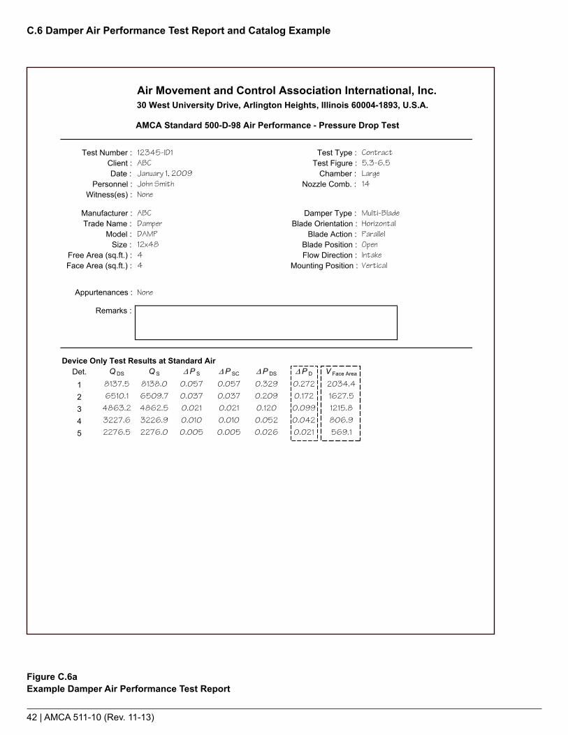
42 | AMCA 511-10 (Rev. 11-13)
C.6 Damper Air Performance Test Report and Catalog Example
Figure C.6aExample Damper Air Performance Test Report
Air Movement and Control Association International, Inc.30 West University Drive, Arlington Heights, Illinois 60004-1893, U.S.A.
Test Number : 12345-ID1 Test Type : ContractClient : ABC Test Figure : 5.3-6.5
: rebmahC : etaD LargePersonnel : John Smith Nozzle Comb. : 14
Witness(es) : None
Manufacturer : ABC Damper Type : Multi-BladeTrade Name : Damper Blade Orientation : Horizontal
Model : DAMP Blade Action : ParallelSize : 12x48 Blade Position : Open
Free Area (sq.ft.) : 4 Flow Direction : IntakeFace Area (sq.ft.) : 4 Mounting Position : Vertical
Appurtenances : None
Remarks :
Device Only Test Results at Standard Air Det. Q DS Q S ∆P S ∆P SC ∆P DS ∆P D V Face Area
1 8137.5 8138.0 0.057 0.057 0.329 0.272 2034.4
2 6510.1 6509.7 0.037 0.037 0.209 0.172 1627.5
3 4863.2 4862.5 0.021 0.021 0.120 0.099 1215.8
4 3227.6 3226.9 0.010 0.010 0.052 0.042 806.9
5 2276.5 2276.0 0.005 0.005 0.026 0.021 569.1###### -999.0###### -999.0###### -999.0###### -999.0###### -999.0
AMCA Standard 500-D-98 Air Performance - Pressure Drop Test
January 1, 2009
These data are not certified by AMCA.
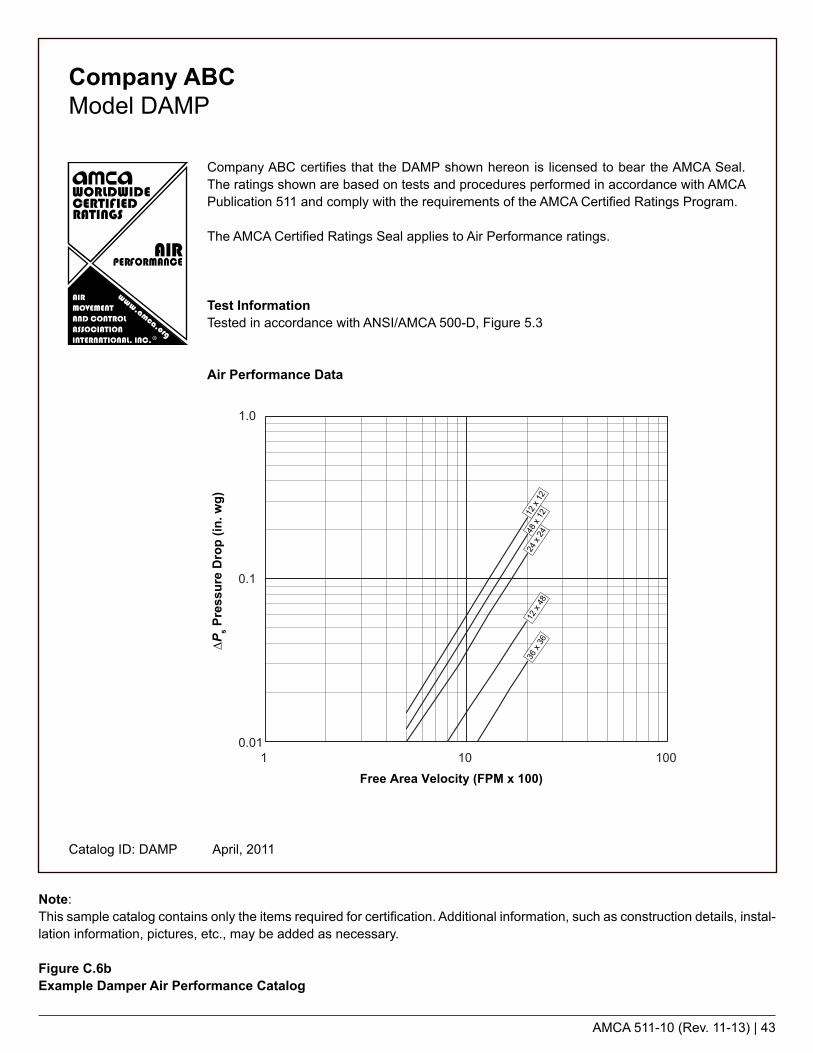
AMCA 511-10 (Rev. 11-13) | 43
1 10 1000.01
0.1
1.0
Free Area Velocity (FPM x 100)
∆Ps P
ress
ure
Dro
p (in
. wg)
12 x
1248
x 12
24 x
2412
x 48
36 x
36
Note:This sample catalog contains only the items required for certification. Additional information, such as construction details, instal-lation information, pictures, etc., may be added as necessary.
Figure C.6bExample Damper Air Performance Catalog
Company ABC certifies that the DAMP shown hereon is licensed to bear the AMCA Seal. The ratings shown are based on tests and procedures performed in accordance with AMCA Publication 511 and comply with the requirements of the AMCA Certified Ratings Program.
The AMCA Certified Ratings Seal applies to Air Performance ratings.
Test InformationTested in accordance with ANSI/AMCA 500-D, Figure 5.3
Air Performance Data
Company ABCModel DAMP
Catalog ID: DAMP April, 2011

44 | AMCA 511-10 (Rev. 11-13)
C.7 Volume Control Damper Leakage Performance Test Report and Catalog Example
Figure C.7aExample Volume Control Damper Air Leakage Test Report
Air Movement and Control Association International, Inc.30 West University Drive, Arlington Heights, Illinois 60004-1893, U.S.A.
Test Number : 12345-L3 Test Type : ContractClient : ABC Test Figure : 5.4 Alternate-6.3
: rebmahC : etaD SmallPersonnel : John Smith
Witness(es) : None
Manufacturer : ABC Damper Type : Multi-BladeTrade Name : Damper Blade Orientation : Horizontal
Model : DAMP Blade Action : OpposedSize : 12x48 Torque : 30 in lbs.
Face Area (sq.ft.) : 4 Flow Direction : ExhaustClosure Method : Torque Arm and Hanging Weights Mounting Position : Vertical
Appurtenances : None
Remarks :
Device Only Test Results at Standard Air :Det. ∆P DS ∆P S Q S Q SC Q DS Q D V Face Area
1 1.025 1.025 0.00 0.00 7.26 7.26 7.26
2 2.050 2.050 0.00 0.00 10.55 10.55 10.55
3 4.100 4.100 0.00 0.00 12.68 12.68 12.68
4 6.149 6.149 0.00 0.00 14.94 14.94 14.94
5 8.199 8.199 0.00 0.00 17.23 17.23 17.2300.999-000.999-
00.999-000.999-00.999-000.999-00.999-000.999-00.999-000.999-
AMCA 500-D-98 Air Leakage Flow Rate Using Ambient Air
January 1, 2009
29.0442.2050.7259.7668.92
29.0442.2050.7259.7668.92

Example 1The company certifying the leakage performance only conducted tests on the two required sizes. The maximum single section width of this model is 60 in. Because only the two required sizes were tested, the catalog data does not have to distinguish the leakage performance at different widths.
Example 2The same company certifies the same damper as in Example 1. This time they test one optional size, 16 in. x 36 in., along with the two required sizes. This allows them to catalog leakage class 1A performance at 1 in. wg on dampers 16 in. and wider.
Example 3The same company again certifies the same damper as in Example 1. This time they test two optional sizes, 16 in. x 36 in. and a 48 in. x 36 in., along with the two required sizes. This not only allows them to catalog leakage class 1A performance at 1 in. wg on dampers 16 in. and wider, but also allows them to catalog class 1 performance at up to 8 in. wg on dampers all the way up to 48 in. wide.
Leakage Class Test Results1 in. wg 4 in. wg 6 in. wg 8 in. wg
12 x 48 in. 1 1 1 160 x 36 in. 1A 1 2 2
Leakage Class Test Results1 in. wg 4 in. wg 6 in. wg 8 in. wg
12 x 48 in. 1 1 1 116 x 36 in. 1A 1 1 160 x 36 in. 1A 1 2 2
Leakage Class Test Results1 in. wg 4 in. wg 6 in. wg 8 in. wg
12 x 48 in. 1 1 1 116 x 36 in. 1A 1 1 148 x 36 in. 1A 1 1 160 x 36 in. 1A 1 2 2
Leakage Class1 in. wg 4 in. wg 6 in. wg 8 in. wg
1 1 2 2
Example Catalog Table
Leakage ClassDamper Width
1 in. wg 4 in. wg 6 in. wg 8 in. wg
Less than 16 in. 1 1 1 1
16 to 60 in. 1A 1 2 2
Example Catalog Table
Leakage ClassDamper Width
1 in. wg 4 in. wg 6 in. wg 8 in. wg
Less than 16 in. 1 1 1 1
16 to 60 in. 1A 1 1 1
48.01 to 60 in. 1A 1 2 2
Example Catalog Table
AMCA 511-10 (Rev. 11-13) | 45
Figure C.7bExample Volume Control Damper Air Leakage Test Results and Corresponding Published Data

46 | AMCA 511-10 (Rev. 11-13)
Note:This sample catalog contains only the items required for certification. Additional information, such as construction details, instal-lation information, pictures, etc., may be added as necessary.
Figure C.7cExample Volume Control Damper Air Leakage Catalog
1 10 1000.01
0.1
1.0
Free Area Velocity (FPM x 100)
∆Ps P
ress
ure
Dro
p (in
. wg)
12 x
1248
x 12
24 x
2412
x 48
36 x
36
Company ABC certifies that the DAMP shown hereon is licensed to bear the AMCA Seal. The ratings shown are based on tests and procedures performed in accordance with AMCA Publication 511 and comply with the requirements of the AMCA Certified Ratings Program.
The AMCA Certified Ratings Seal applies to Air Leakage and Air Performance ratings.
Test InformationAir leakage is based on operation between 32 °F and 120 °FTested for air leakage in accordance with ANSI/AMCA Standard 500-D, Figure 5.4Tested for air performance in accordance with ANSI/AMCA 500-D, Figure 5.3
TorqueData are based on a torque of 7.5 in-lb/ft2 applied to close and seat the damper during the test.
Leakage Performance
Company ABCModel DAMP
Leakage Class
Damper Width 1 in. wg 4 in. wg 6 in. wg 8 in. wg
Less than 16 in. 1 1 1 116 in. to 48 in. 1A 1 1 148.01 in. to 60 in. 1A 1 2 2
Air Performance
Catalog ID: AL123 April, 2011

AMCA 511-10 (Rev. 11-13) | 47
C.8 Ultra-Low-Leakage Damper Leakage Test Report and Catalog Example
Figure C.8aExample Ultra-Low-Leakage Damper Air Leakage Test Report
Air Movement and Control Association International, Inc.30 West University Drive, Arlington Heights, Illinois 60004-1893, U.S.A.
: epyT tseT1L-54321 : rebmuN tseT ContractClient : ABC Test Figure : 5.4 Alternate-6.3
: rebmahC : etaD SmallPersonnel : John Smith
Witness(es) : None
Manufacturer : ABC Damper Type : Multi-bladeTrade Name : Damper Blade Orientation : Horizontal
Model : ULL-DAMP Blade Action : ParallelSize : 12x60 Torque : 37.5" lbs
Face Area (sq.ft.) : 5 Flow Direction : IntakeClosure Method : Torque Arm and Hanging Weights Mounting Position : Vertical
Appurtenances : None
Remarks :
Device Only Test Results at Standard Air :Det. ∆P DS ∆P S Q S Q SC Q DS Q D V Face Area
1 1.025 1.025 0.00 0.00 7.57 7.57 1.512 2.051 2.051 0.00 0.00 10.77 10.77 2.153 4.102 4.102 0.00 0.00 15.22 15.22 3.044 6.153 6.153 0.00 0.00 18.68 18.68 3.745 8.204 8.204 0.00 0.00 21.52 21.52 4.30
00.999-000.999-00.999-000.999-00.999-000.999-00.999-000.999-00.999-000.999-
AMCA 500-D-98 Air Leakage Flow Rate Using Ambient Air
January 1, 2009
These data are not certified by AMCA
78.1192.45
114.45
28.4550.30
15.6218.4922.89
5.6910.06
78.1192.45
114.45
28.4550.30
8.0110.0512.1314.0716.10
4.755.335.856.306.74
8.0110.0512.1314.0716.10

48 | AMCA 511-10 (Rev. 11-13)
Note:This sample catalog contains only the items required for certification. Additional information, such as construction details, instal-lation information, pictures, etc., may be added as necessary.
Figure C.8bExample Ultra-Low Leakage Damper Air Leakage Catalog
Company ABC certifies that the ULL-DAMP shown hereon is licensed to bear the AMCA Seal. The ratings shown are based on tests and procedures performed in accordance with AMCA Publication 511 and comply with the requirements of the AMCA Certified Ratings Program.
The AMCA Certified Ratings Seal applies to Air Leakage ratings.
Test InformationAir leakage is based on operation between 32 °F and 104 °FTested for air leakage in accordance with ANSI/AMCA Standard 500-D, Figure 5.4
TorqueData are based on a torque of 7.5 in-lb/ft2 applied to close and seat the damper during the test.
Leakage Performance
Company ABCModel ULL-DAMP
Leakage (cfm/ft² of face area)
Sta
tic P
ress
ure
(in. w
.g.)
60 x
12
60 x
60
12 x
60
Catalog ID: ULL-DAMP April, 2011
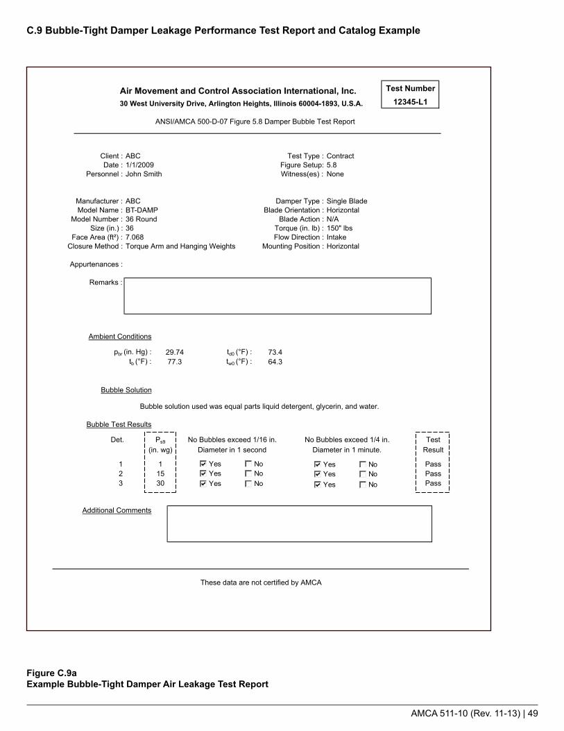
AMCA 511-10 (Rev. 11-13) | 49
C.9 Bubble-Tight Damper Leakage Performance Test Report and Catalog Example
Figure C.9aExample Bubble-Tight Damper Air Leakage Test Report
: epyT tseT: tneilC:puteS erugiF: etaD: )se(ssentiW: lennosreP
: epyT repmaD: rerutcafunaM: noitatneirO edalB: emaN ledoM: noitcA edalB: rebmuN ledoM: )bl .ni( euqroT: ).ni( eziS: noitceriD wolF: )²tf( aerA ecaF: noitisoP gnitnuoM: dohteM erusolC
Appurtenances :
Remarks :
Ambient Conditions
pbr t: )gH .ni( d0 (°F) :tb t: )F°( w0 (°F) :
Bubble Solution
Bubble solution used was equal parts liquid detergent, glycerin, and water.
Bubble Test Results
No Bubbles exceed 1/16 in. No Bubbles exceed 1/4 in. TestDiameter in 1 second Diameter in 1 minute. Result
123
Additional Comments
PassPassPass30
15
29.7477.3
73.464.3
edalB elgniSCBAlatnoziroH
150" lbsIntakeHorizontal
5.8John Smith
A/NdnuoR 63
1/1/2009None
Air Movement and Control Association International, Inc. Test Number
30 West University Drive, Arlington Heights, Illinois 60004-1893, U.S.A. 12345-L1
ANSI/AMCA 500-D-07 Figure 5.8 Damper Bubble Test Report
tcartnoCCBA
These data are not certified by AMCA
367.068Torque Arm and Hanging Weights
Ps9Det.(in. wg)
1 YesYesYes
NoNoNo
YesYesYes
NoNoNo
BT-DAMP

50 | AMCA 511-10 (Rev. 11-13)
Note:This sample catalog contains only the items required for certification. Additional information, such as construction details, instal-lation information, pictures, etc., may be added as necessary.
Figure C.9bExample Bubble-Tight Damper Air Leakage Catalog
Company ABC certifies that the BT-DAMP shown hereon is licensed to bear the AMCA Seal. The ratings shown are based on tests and procedures performed in accordance with AMCA Publication 511 and comply with the requirements of the AMCA Certified Ratings Program.
The AMCA Certified Ratings Seal applies to Air Leakage ratings.
Test InformationAir leakage is based on operation between 32 °F and 120 °F
Performance DataDampers are bubble-tight up to 30 in. wg differential pressure.
Torque Table
Company ABCModel BT-DAMP
Damper Size (in.)12” round36” round
Required Torquein-lb in-lb/ft2
25 31.8150 21.2
Catalog ID: BT-DAMP April, 2011

AMCA 511-10 (Rev. 11-13) | 51
C.10 Backdraft Damper Leakage Performance Test Report and Catalog Example
Figure C.10aExample Backdraft Damper Air Leakage Test Report
Air Movement and Control Association International, Inc.30 West University Drive, Arlington Heights, Illinois 60004-1893, U.S.A.
Test Number : 12345-L1 Test Type : ContractClient : ABC Test Figure : 5.4 Alternate-6.3
: rebmahC : etaD SmallPersonnel : John Smith
Witness(es) : None
Manufacturer : ABC Damper Type : Multi-BladeTrade Name : BD-Damp Blade Orientation : Horizontal
Model : BD-Damp 24 Blade Action : ParallelSize : 24x24 Torque : N/A
Face Area (sq.ft.) : 4 Flow Direction : IntakeClosure Method : Gravity Mounting Position : Vertical
Appurtenances : None
Remarks :
Device Only Test Results at Standard Air :Det. ∆P DS ∆P S Q S Q SC Q DS Q D V Face Area
1 1.025 1.025 0.00 0.00 7.27 7.27 5.72
2 2.051 2.051 0.00 0.00 10.12 10.12 10.62
3 4.102 4.102 0.00 0.00 12.86 12.86 18.31
4 6.153 6.153 0.00 0.00 14.95 14.95 24.95
5 8.204 8.204 0.00 0.00 17.30 17.30 42.3000.999-000.999-00.999-000.999-00.999-000.999-00.999-000.999-00.999-000.999-
AMCA 500-D-98 Air Leakage Flow Rate Using Ambient Air
January 1, 2009
These data are not certified by AMCA
5.7210.6218.31
24.9542.30

52 | AMCA 511-10 (Rev. 11-13)
Note:This sample catalog contains only the items required for certification. Additional information, such as construction details, instal-lation information, pictures, etc., may be added as necessary.
Figure C.10bExample Backdraft Damper Air Leakage Catalog
Company ABC certifies that the BD-DAMP shown hereon is licensed to bear the AMCA Seal. The ratings shown are based on tests and procedures performed in accordance with AMCA Publication 511 and comply with the requirements of the AMCA Certified Ratings Program.
The AMCA Certified Ratings Seal applies to Air Leakage and Air Perfomance ratings.
Test InformationAir leakage is based on operation between 32 °F and 120 °FTests for air leakage were conducted in accordance with ANSI/AMCA Standard 500-D, Figure 5.4, in the intake direction, on a 24 in. x 24 in. sample
Company ABCModel BD-DAMP
0.01
0.1
1
Face Area Velocity (fpm)
Stat
ic P
ress
ure
Dro
p (in
. wg)
10,0001,000100
Leakage (cfm per ft² of face area)
Sta
tic P
ress
ure
(inch
es w
.g.)
10
1
3
2
4
5
76
89
101 2 3 4 5 6 7 8 9 6020 30 40 50 80 100
Air Performance Data Air Leakage Data
Catalog ID: BD-DAMP April, 2011

AMCA 511-10 (Rev. 11-13) | 53
C.11 Gravity Ventilator Air Performance Test Report and Catalog Example
Figure C.11aExample Gravity Ventilator Air Performance Test Report
Air Movement and Control Association International, Inc.30 West University Drive, Arlington Heights, Illinois 60004-1893, U.S.A.
Test Number : 12345-E1 Test Type : ContractClient : ABC Test Figure : 5.5-6.5
: rebmahC : etaD LargePersonnel : John Smith Nozzle Comb. : 14
Witness(es) : None
Manufacturer : ABC Louver Type : Trade Name : Gravity Ventilator Blade Orientation :
Model : GV24 Blade Action : Size : 24x24 Blade Position :
Core Area (sq.ft.) : 10.08 Flow Direction : ExhaustFree Area (sq.ft.) : 6.24 Blade Type : Fixed
Appurtenances : None
Remarks :
Recorded Data : Det. p br t b p bc t do t wo t d5 P S8 t d8 ∆P n
1 29.380 76.4 29.244 75.7 56.7 81.2 0.610 79.8 4.7002 29.380 76.4 29.244 75.7 56.7 81.2 0.390 79.8 3.0003 29.380 76.4 29.244 75.7 56.7 81.2 0.240 79.8 1.8004 29.380 76.4 29.244 75.7 56.7 81.2 0.110 79.8 0.8005 29.380 76.4 29.244 75.7 56.7 81.2 0.040 79.8 0.305
Test Results at Standard Air : Det. ∆P DS Q DS V Free Area C D C D Class
1 0.048 2842.1 2038.2 0.22 32 0.128 7633.1 1627.5 0.22 33 0.251 5907.1 1259.5 0.22 34 0.115 3930.1 838.0 0.22 35 0.042 2418.9 515.7 0.22 3
January 1, 2009
AMCA Standard 500-L-99 Air Performance - Pressure Drop Test
These data are not certified by AMCA
0.7090.4400.2630.1070.027
1327.21064.2808.9529.4276.2
8282.36640.85047.33303.21723.4
Curb height: 12 in.Screen: 1/2 in. x 1/2 in. galvanized mesh

54 | AMCA 511-10 (Rev. 11-13)
Note:This sample catalog contains only the items required for certification. Additional information, such as construction details, instal-lation information, pictures, etc., may be added as necessary.
Figure C.11bExample Gravity Ventilator Air Performance Catalog
Company ABC certifies that the GV shown hereon is licensed to bear the AMCA Seal. The ratings shown are based on tests and procedures performed in accordance with AMCA Publi-cation 511 and comply with the requirements of the AMCA Certified Ratings Program.
The AMCA Certified Ratings Seal applies to Air Performance ratings.
Test InformationTested in accordance with AMCA Figure 5.5.Test data include the effects of a 1/2 in. x 1/2 in. galvanized mesh screenThe model GV curb height is 12 in.
Performance DataPressure drop data were obtained in the exhaust mode
Company ABCModel GV
0.01
0.1
1.0
100 1000 10000
Free Area Velocity (FPM)
24 x
24
12 x
12
36 x
36
∆Ps P
ress
ure
Dro
p (in
. wg)
Catalog ID: GV April, 2011

AMCA 511-10 (Rev. 11-13) | 55
C.12 Spiral Duct Leakage Performance Test Report and Catalog Example
Figure C.12aExample Spiral Duct Air Leakage Performance Test Report
: epyT tseT: tneilC:puteS erugiF: etaD: )se(ssentiW: lennosreP
: ).ni( htgneL: rerutcafunaM: ).ni( retemaiD: emaN ledoM
Model Number : Duct Surface Area (ft²) :Gauge Size :
Remarks :
Data At Test Conditions
Recorded Barometric Pressure, pbr (in. Hg) :Temperature at Barometer, tdb (°F) :Ambient Dry-Bulb Temperature, td0 (°F) :Ambient Wet-Bulb Temperature, tw0 (°F) :Ambient Air Density, ρ0 (lbm/ft³) :
Test Specimen Static Pressure (in. wg) :Airflow Leakage Measured (SCFH) :
Calculated Data
Airflow Leakage Measured (SCFM) :Airflow Leakage (SCFM per 100 ft² Duct Surface) :
Data at Standard Air Conditions
Airflow Leakage at Standard Air :
These data are not certified by AMCA
26
Air Movement and Control Association International, Inc.30 West University Drive, Arlington Heights, Illinois 60004-1893, U.S.A.
ANSI/ASHRAE/SMACNA Standard 126-2008 Spiral Duct Leakage Test Report
ABC
62.83
ABCSpiral Duct
Contract
John Smith1None
12024
0.0830.133
SP26
January 1, 2009
51.30.0796
155
29.5974.268.0
0.141 0.240
SIm³/hr per 9.29 m²SCFM per 100 ft²
I-P
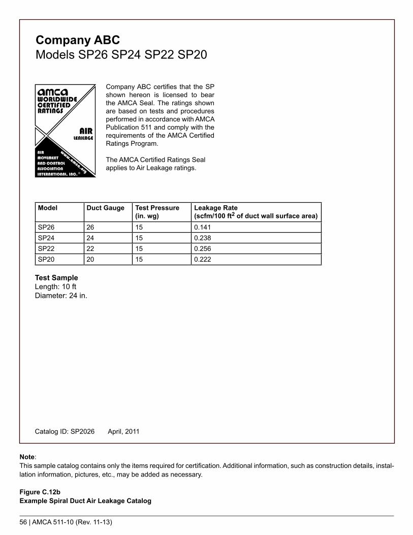
56 | AMCA 511-10 (Rev. 11-13)
Note:This sample catalog contains only the items required for certification. Additional information, such as construction details, instal-lation information, pictures, etc., may be added as necessary.
Figure C.12bExample Spiral Duct Air Leakage Catalog
Company ABCModels SP26 SP24 SP22 SP20
Company ABC certifies that the SP shown hereon is licensed to bear the AMCA Seal. The ratings shown are based on tests and procedures performed in accordance with AMCA Publication 511 and comply with the requirements of the AMCA Certified Ratings Program.
The AMCA Certified Ratings Seal applies to Air Leakage ratings.
Model Duct Gauge Test Pressure (in. wg)
Leakage Rate (scfm/100 ft2 of duct wall surface area)
SP26 26 15 0.141SP24 24 15 0.238SP22 22 15 0.256SP20 20 15 0.222
Test SampleLength: 10 ftDiameter: 24 in.
Catalog ID: SP2026 April, 2011
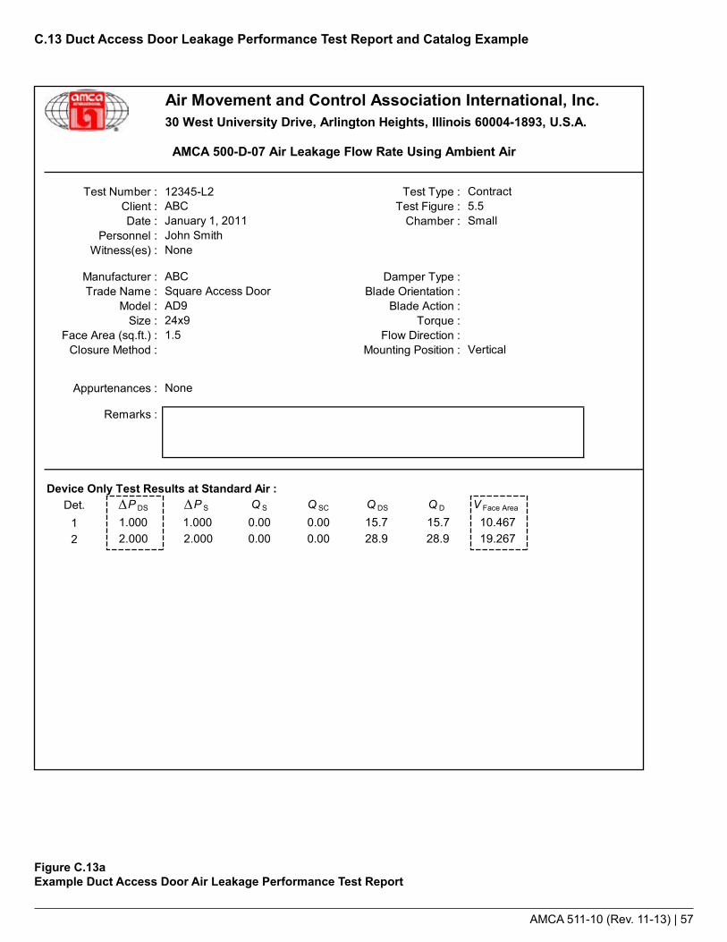
AMCA 511-10 (Rev. 11-13) | 57
C.13 Duct Access Door Leakage Performance Test Report and Catalog Example
Figure C.13aExample Duct Access Door Air Leakage Performance Test Report
Air Movement and Control Association International, Inc.30 West University Drive, Arlington Heights, Illinois 60004-1893, U.S.A.
: epyT tseT2L-54321 : rebmuN tseT ContractClient : ABC Test Figure : 5.5
: rebmahC : etaD SmallPersonnel : John Smith
Witness(es) : None
Manufacturer : ABC Damper Type : Trade Name : Square Access Door Blade Orientation :
Model : AD9 Blade Action : Size : 24x9 Torque :
Face Area (sq.ft.) : 1.5 Flow Direction : : noitisoP gnitnuoM : dohteM erusolC Vertical
Appurtenances : None
Remarks :
Device Only Test Results at Standard Air :Det. P DS P S Q S Q SC Q DS Q D V Face Area
1 1.000 1.000 0.00 0.00 8.13 8.13 8.132 2.000 2.000 0.00 0.00 11.57 11.57 11.57
00.999-000.999-00.999-000.999-00.999-000.999-00.999-000.999-
AMCA 500-D-07 Air Leakage Flow Rate Using Ambient Air
January 1, 2011
These data are not certified by AMCA
∆∆15.728.9 28.9 19.267
15.7 10.467
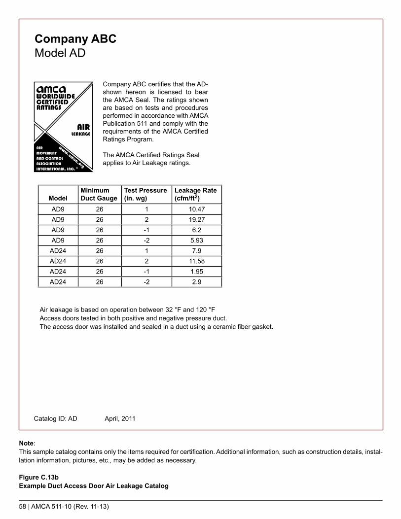
58 | AMCA 511-10 (Rev. 11-13)
Note:This sample catalog contains only the items required for certification. Additional information, such as construction details, instal-lation information, pictures, etc., may be added as necessary.
Figure C.13bExample Duct Access Door Air Leakage Catalog
Company ABCModel AD
Company ABC certifies that the AD-shown hereon is licensed to bear the AMCA Seal. The ratings shown are based on tests and procedures performed in accordance with AMCA Publication 511 and comply with the requirements of the AMCA Certified Ratings Program.
The AMCA Certified Ratings Seal applies to Air Leakage ratings.
ModelMinimum Duct Gauge
Test Pressure (in. wg)
Leakage Rate (cfm/ft2)
AD9 26 1 10.47AD9 26 2 19.27AD9 26 -1 6.2AD9 26 -2 5.93
AD24 26 1 7.9AD24 26 2 11.58AD24 26 -1 1.95AD24 26 -2 2.9
Catalog ID: AD April, 2011
Air leakage is based on operation between 32 °F and 120 °F Access doors tested in both positive and negative pressure duct.The access door was installed and sealed in a duct using a ceramic fiber gasket.

AMCA 511-10 (Rev. 11-13) | 59
C.14 Flat Oval Spiral Duct Leakage Performance Test Report and Catalog Example
Figure C.14aExample Flat Oval Spiral Duct Air Leakage Performance Test Report
: epyT tseT: tneilC:puteS erugiF: etaD: )se(ssentiW: lennosreP
: ).ni( htgneL: rerutcafunaM: ).ni( retemaiD: emaN ledoM
Model Number : Duct Surface Area (ft²) :Gauge Size :
Remarks :
Data At Test Conditions
Recorded Barometric Pressure, pbr (in. Hg) :Temperature at Barometer, tdb (°F) :Ambient Dry-Bulb Temperature, td0 (°F) :Ambient Wet-Bulb Temperature, tw0 (°F) :Ambient Air Density, ρ0 (lbm/ft³) :
Test Specimen Static Pressure (in. wg) :Airflow Leakage Measured (SCFH) :
Calculated Data
Airflow Leakage Measured (SCFM) :Airflow Leakage (SCFM per 100 ft² Duct Surface) :
Data at Standard Air Conditions
Airflow Leakage at Standard Air :
These data are not certified by AMCA
26
Air Movement and Control Association International, Inc.30 West University Drive, Arlington Heights, Illinois 60004-1893, U.S.A.
ANSI/ASHRAE/SMACNA Standard 126-2008 Flat Oval Spiral Duct Leakage Test Report
ABC
62.83
ABCFlat Oval Spiral Duct
Contract
John Smith1None
12012 x 30.85
0.0830.133
FO26
January 1, 2009
51.30.0796
155
29.5974.268.0
0.141 0.240
SIm³/hr per 9.29 m²SCFM per 100 ft²
I-P
Duct Size (in.)

60 | AMCA 511-10 (Rev. 11-13)
Note:This sample catalog contains only the items required for certification. Additional information, such as construction details, instal-lation information, pictures, etc., may be added as necessary.
Figure C.14bExample Flat Oval Spiral Duct Air Leakage Catalog
Company ABCModels FO26 FO24 FO22 FO20
Company ABC certifies that the SP shown hereon is licensed to bear the AMCA Seal. The ratings shown are based on tests and procedures performed in accordance with AMCA Publication 511 and comply with the requirements of the AMCA Certified Ratings Program.
The AMCA Certified Ratings Seal applies to Air Leakage ratings.
Model Duct Gauge Test Pressure (in. wg)
Leakage Rate (scfm/100 ft2 of duct wall surface area)
FO26 26 15 0.141FO24 24 15 0.238FO22 22 15 0.256FO20 20 15 0.222
Test SampleLength: 10 ftDuct Size: 12 in. x 30.85 in.
Catalog ID: FO2026 April, 2011

AIR MOVEMENT AND CONTROLASSOCIATION INTERNATIONAL, INC.
30 West University DriveArlington Heights, IL 60004-1893 U.S.A.
Tel: (847) 394-0150 Fax: (847) 253-0088 Email : [email protected] Web: www.amca.org
The Air Movement and Control Association International Inc. is a not-for-profit international association of the world’s manufacturers of related air system equipment, primarily but not limited to fans, louvers, dampers, air curtains, airflow measurement stations, acoustic attenuators and other air system components for the industrial, commercial and residential markets.