Embed Size (px)
Citation preview

Amateur-Built Fabrication and Assembly Checklist (2009) Job Aid
AA
1
AmmmaaattteeeuuurrrBBBuuuiiilllttt FFFaaabbbrrriiicccaaatttiiiooonnn aaannnddd AAAsssssseeemmmbbblllyyy CCChhheeeccckkkllliiisssttt
JJJooobbb AAAiiiddd
AAAmmmaaattteeeuuurrrBBBuuuiiilllttt FFFaaabbbrrriiicccaaatttiiiooonnn
aaannnddd AAAsssssseeemmmbbblllyyy CCChhheeeccckkkllliiisssttt (((222000000999))) JJJooobbb AAAiiiddd
Production and Airworthiness Division, AIR200 Evaluation and Special Projects Branch, AIR240
Federal Aviation Administration Washington, D.C.
August 25, 2011

Amateur-Built Fabrication and Assembly Checklist (2009) Job Aid
2
THIS PAGE INTENTIONALLY
LEFT BLANK

Amateur-Built Fabrication and Assembly Checklist (2009) Job Aid
Table of Contents
Page
Introduction..............................................................................................................3 Fabrication and Assembly ......................................................................................6 Commercial Assistance............................................................................................7 Credit Allocation ......................................................................................................7 Original Condition ...................................................................................................9 The Wings (Metal) .................................................................................................10 Standard Kit ...........................................................................................................18 The Fuselage (Metal) .............................................................................................34 Composites and Other materials ..........................................................................46 Fuselage Section Composite..................................................................................48 Wings (Composite).................................................................................................52 Various Wood Parts Examples .............................................................................58 Fuselage Components (Wood) ..............................................................................64 Propulsion Section .................................................................................................70 Landing Gear Section ............................................................................................76 Cockpit Section ......................................................................................................80 Conclusion ..............................................................................................................83
3

Amateur-Built Fabrication and Assembly Checklist (2009) Job Aid
Introduction The purpose of this Job Aid is to provide the minimum knowledge necessary to successfully determine at the time of an airworthiness (A/W) inspection whether an amateur-built aircraft constructed from a kit can meet the major portion requirement of Title 14, Code of Federal Regulations (14 CFR) § 21.191(g). The primary tool to determine major portion is the Amateur-Built Fabrication and Assembly Checklist (2009). See FAA Order 8130.35, Amateur-Built Aircraft National Kit Evaluation Team (NKET), or FAA Advisory Circular (AC) 20-27, Certification and Operation of Amateur-Built Aircraft, for a copy of the checklist. Determining major portion at time of airworthiness is a difficult and time-consuming process because the amateur-built aircraft is complete and, according to FAA requirements, ready for flight. This status complicates matters and makes the major portion determination more difficult but not impossible. The Fabrication/Assembly Operation Checklist, FAA Form 8000-38 was revised in 2009. The new checklist has 4 columns versus 2 columns and credit for each itemized task can be incrementally awarded as a ratio or percentage of task completion to reflect who performed how much of the task.
A B C D FABRICATION AND ASSEMBLY TASKS
Mfr Kit/Part/Component
Commercial Assistance
Am-Builder Assembly
Am-Builder Fabrication
A primary reason for implementing the new checklist was to eliminate the “all or nothing” methodology previously used that frequently provided full credit to be awarded to the amateur-builder for performing a minor fabrication task such as sanding, drilling and trimming. This checklist is the primary tool used by the NKET when evaluating an amateur-built kit at the manufacturer’s facility. The scores allocated to the kit manufacturer and the amateur builder columns are totaled at the bottom of the checklist in a Summary Section. They reflect the relative portions of the aircraft fabricated and assembled by the kit manufacturer, the amateur builder or the company (if any) providing commercial assistance. At the end of the A/W inspection, the amateur builder must accumulate, through combination of the totals of column “C” and “D,” a score greater than 50%. The following excerpt from FAA Order 8130.2F, Airworthiness Certification of Aircraft and Related Products , defines major portion and cites the regulatory basis:
“DETERMINATION OF MAJOR PORTION. The determination of major portion is made by evaluating the amount of work accomplished by the amateur builder(s) against the total amount of work necessary to complete the aircraft, excluding standard procured items. The major portion of the aircraft is defined as more than 50 percent of the fabrication and assembly tasks, commonly referred to as the “51-percent rule.” An aircraft is not eligible for an experimental amateur-built certificate under § 21.191(g) if the major portion of the aircraft fabrication and assembly tasks are not completed by an amateur builder(s).”
4

Amateur-Built Fabrication and Assembly Checklist (2009) Job Aid
For a discussion of when an applicant may use “Prior Policy” (use of the previous checklist, FAA Form 8310-38) for major portion determination, please refer to FAA Order 8130.2, Chapter 4, Special Airworthiness Certification, Section 9, Experimental Amateur-Built Airworthiness Certifications. For guidance provided to the amateur builder, see “What to Know Before Building an Amateur-Built Aircraft” in AC 20-27, where the information set forth in the order is reiterated to advise the builder. FAA Order 8130.2 and AC 20-27 allow unlimited use of commercial assistance on non-checklist items such as painting; installation of interior upholstery or avionics; fabrication of engines, propellers, wheels and brake assemblies; and standard aircraft hardware as listed in paragraph 8b(2) without triggering a requirement to use the new policy/checklist.
The following excerpt from FAA Order 8130.2 lists various situations where the new checklist must be used to make a major portion determination. There are multiple conditions which trigger the new checklists’ use, the most common being those events described in paragraphs a.(2), (4), and (6) below.
“FAA Use of the Amateur-Built Fabrication and Assembly Checklist (2009). The Amateur-Built Fabrication and Assembly Checklist (2009) is to be used by the FAA as an aid in determining compliance with the major portion requirement of § 21.191(g). A specific checklist has been developed for fixed-wing aircraft. Checklists for other types of aircraft will be developed. Instructions for completion are included on the form. Refer to FAA Order 8130.35, Amateur-Built Aircraft National Kit Evaluation Team (NKET), for a copy and instructions of the checklist. The Amateur-Built Aircraft Fabrication and Assembly Checklist (2009) must be used when― (1) Performing FAA kit evaluations by the NKET to determine if an aircraft fabricated and assembled from a kit may meet the major portion requirement of § 21.191(g). (2) Commercial assistance was used by the amateur builder(s) during construction. (3) The amateur builder made modifications to an aircraft kit included on the FAA List of Amateur-Built Aircraft Kits that potentially affects the major portion determination. (4) The aircraft was built from prefabricated major components that are readily available from aircraft parts suppliers, other than those components listed in paragraph 149a (2). (5) The aircraft was built using any salvaged components or used parts from aircraft that have been type certificated. For additional details and limitations affecting this practice, refer to paragraph 149b through d below. (6) The aircraft was built from a kit that has not been evaluated or found eligible by the FAA. (7) Providing guidance to a kit manufacturer to determine if a proposed amateur-built kit may meet the major portion requirement of § 21.191(g). (8) There are questions that arise as to the determination of major portion.”
5

Amateur-Built Fabrication and Assembly Checklist (2009) Job Aid
Clarification for paragraph (2) above is found in the following paragraph entitled “Use of Commercially Produced Products and Articles,” in the same order states:
“Items such as engines, engine accessories, propellers, rotor blades, rotor hubs, tires, wheel and brake assemblies, instruments, and standard aircraft hardware, including pulleys, bell cranks, rod ends, bearings, bolts, rivets, hot air balloon burners, and fuel tanks, are acceptable and may be procured on the open market. The use of these items is not counted against the amateur builder or kit manufacturer when the FAA determines whether the amateur-built aircraft has met the major portion requirement.”
The components listed in the above paragraph are considered non-checklist items and no credit is assessed against the manufacturer or builder for their use in building the aircraft. The following excerpt from AC 20-27 reiterates the same concept for the amateur builder.
“Purchasing Prefabricated or Assembled Components and Materials.
(1) To meet the intent of § 21.191(g) and to be eligible for an amateur-built experimental airworthiness certificate, you need to present satisfactory evidence to show that the aircraft was not fabricated and assembled from completely prefabricated parts or kits. However, the FAA does not expect you to fabricate every part that makes up the aircraft. Items such as engines and engine accessories, propellers, landing gear, rotor blades, rotor hubs, tires, wheel and brake assemblies, instruments, and standard aircraft hardware (such as pulleys, bell cranks, rod ends, bearings, bolts, and rivets) are acceptable and may be procured on the open market.”
The use of commercial assistance for non-checklist items does not, by itself, trigger the requirement to use the new Amateur-Built Fabrication and Assembly Checklist (2009). Fabrication and Assembly FAA Order 8130.2 defines fabrication as: “To perform work on any material, part or component, such as layout, bending, countersinking, straightening, cutting, sewing, gluing/bonding, lay-up, forming, shaping, trimming, drilling, de-burring, machining, applying protective coatings, surface preparation and priming, riveting, welding or heat-treating, transforming the material, part or component toward or into its finished state. “ The FAA does not define “assembly.” However, such work that does not fall under the definition of fabrication is considered assembly. In work such as riveting, there can be some confusion concerning different components. The guidance this guide offers depends on the component, task at hand, and how it is being applied. When attaching a metal skin to a basic wing structure (i.e., the spar and ribs forming the basic wing structure) the riveting that fastens the skin to the ribs should be considered assembly work, not fabrication. However, consider a different major component found in almost every kit – the firewall. The NKET has observed that most of the amateur-built kits provide the individual firewall components, including the sheet metal, angles, uprights, doublers, nut plates, etc. Usually these
6

Amateur-Built Fabrication and Assembly Checklist (2009) Job Aid
parts are cut to approximate size but require significant work to transform into a finished component. This involves a lot of riveting besides the requisite drilling, trimming and deburring found in most of the other parts. These actions will be attributed to the fabrication task for the firewall, not assembly. The assembly task will be used when attaching the firewall to the fuselage. Incidentally, the firewall tasks were inadvertently left off of the checklist at inception. The NKET has added them to the Propulsion section at task P28 and P29. Most of the credit awarded to the builder of an amateur-built kit, especially in quick build kits, will be for assembly tasks. Commercial Assistance FAA Order 8130.2 refers to commercial assistance in the paragraph entitled, “Providing Commercial and/or Educational Assistance” as “any fabrication or assembly tasks contracted to another party (that is for compensation hire) or provided by a commercial assistance center” and also in the notes for the “Use of Prior Policy” flowchart as “commercial assistance means to provide assistance with fabricating or assembling amateur-built aircraft for cash, services, or other tender. This does not include one builder helping another without compensation.” AC 20-27 defines commercial assistance as “provid[ing] assistance with fabricating or assembling amateur-built aircraft for cash, services, or other tender. This does not include one builder helping another without compensation.” For checklist tasks where the builder has indicated that commercial assistance was used, a credit allocation must be made for proper division of work. In many instances, the allocation may be very simple when the builder indicates that the entire task was contracted for. However, if this is not the case, then the following must be applied: The original condition of a component or task prior to commercial assistance must be ascertained (usually with photographic evidence), then the builder’s contribution to completing the task, if any, must be determined, before the ratio of work attributed to commercial assistance can be determined. Remember to apply the following instructions and evaluative process to all task items, no matter who completed the task (the builder, the manufacturer, or a commercial assistance provider), and the result will be acceptable. Credit Allocation Credit allocation for each individual task involves a simple decision process. The important factors are deciding which column properly receives the credit (Manufacture, Commercial assistance or Builder), and how much credit (e.g., full points or incremental portion such as 1/10th) is actually allocated. One methodology the NKET has adopted is to apportion the credit allocations according to the table below, which uses the amount of work involved to complete the task as a metric.
Minor level work 0.1 to 0.2 point Medium level work 0.3 to 0.5 point Major level work 0.6 to 0.9 point Completely fabricated from raw materials or complete assembly
1.0 point (full credit)
7

Amateur-Built Fabrication and Assembly Checklist (2009) Job Aid
By utilizing this methodology for task evaluation, an evaluator can more precisely and fairly allocate the proper credit to each application. For example, sanding, drilling, and deburring applied to a component provided by a manufacturer, (i.e., drilling a few holes and deburring the edges); a minor credit of 0.1 or at most 0.2 is warranted. If the amount of work is more significant (e.g., cutting, drilling, trimming, deburring, and other minor applications), a medium credit of 0.3 or 0.4 may be fair. In those instances where the amateur-builder conducted a greater amount of fabrication such as cutting tubing, trimming the ends, sanding it, bending it and drilling attach points, a major credit can be allocated, such as 0.6 or 0.7 points. If the builder creates a component from raw materials using a drawing, then and only then may a full credit of 1.0 point be awarded in the fabrication column “D” on the checklist. For example, if a raw material like aluminum sheeting is provided by the kit manufacturer, and the builder measures, marks, cuts, trims, bends, forms, deburs, and drills the material to form the wing skin, the builder would receive the full credit for fabricating the skin. As stated above, the builder in most instances is awarded full credit for assembly tasks, unless he used commercial assistance. As previously discussed, the NKET uses the checklist to record the amount of fabrication and assembly accomplished by a kit manufacturer. This documents a starting point for the amount of fabrication and assembly available towards completion of the aircraft kit for the amateur builder. The checklist may also be used if an amateur builder has constructed an aircraft either from plans/scratch or by using a purchased kit that is not included on the FAA List of Eligible Kits previously evaluated. Listed kits have been determined through evaluation to allow an amateur-builder, following the instructions in the manufacturer’s manual, to meet the major portion fabrication and assembly requirement of § 21.191(g). Additionally, by using the checklist, a kit manufacturer can estimate whether a proposed kit would allow a builder to meet major portion requirements. If this benchmark is not reached, the manufacturer can then adjust the kit contents or configuration to meet the major portion requirement. The NKET has benefited from multiple practice sessions and group meetings to discuss the procedures and methodology to apply in estimating and awarding the proper amount of credit for tasks on the checklist. Even more important, the NKET onsite evaluation takes place at the manufacturer’s facility with the kit in its “as sold configuration” status with each individual component supplied in the kit laid out in a hangar bay or work shop for easy access and inspection by the team. The NKET evaluators also have the benefit of discussing the construction project, plans, drawings, and builder’s manual with the company technician while on site. Original Condition In order to award the proper credit to an individual task on the checklist, the original condition of the component in question as it was received from the manufacturer must be known. This is critical to the process. If the component’s original condition as received in the kit can not be ascertained, it is virtually impossible to make a proper assessment as to which column to award the credit for the task. The most essential information for this determination are photographs (either from the manufacturer or contained in the builder’s project logbook that documents the construction process) and the person(s) fabricating and assembling the aircraft. This reflects the requirement for the builder to provide sufficient evidence/documentation to detail the
8

Amateur-Built Fabrication and Assembly Checklist (2009) Job Aid
construction and inspections of their aircraft. These records, if done correctly, should provide an accurate record indicating what was fabricated and assembled and the date the activity was performed. Some pictures will usually be provided by the manufacturer with the kit. Below is a popular amateur-built standard aircraft kit, complete and placed on a hangar floor showing each individual component in the original condition as received from the manufacturer and out of the shipping crate. Evidence like this is critical in making credit allocation determinations. In all likelihood, the process of evaluating an already completed aircraft for major portion will probably require more time reviewing the builder’s log and pictures, accompanied with a lengthy question and answer period with the builder, than time spent inspecting the aircraft. All of these processes should be supported with numerous photos showing the construction of the wing in various stages of completion. FAA Order 8130.2 says the builder “must have satisfactory evidence to support the major portion requirement;” that “this evidence is typically in the form of a builder’s log or equivalent, and includes photographs that document the multitude of steps included in each of the listed tasks” and finally, “if the builder’s log or equivalent does not provide sufficient detail, the FAA may not be able to find compliance with 14 CFR § 21.191(g).” Essentially, the builder must present “satisfactory evidence” in the form of photographic representation on the step-by-step fabrication and assembly process during the aircraft construction for this procedure to be successful.
Standard Build Kit A good deal of information can be obtained from the two photos above and below. The photo above depicts a popular standard build kit and the photo below is a popular amateur-built quickbuild kit. Take a moment to compare the two photographs. The quickbuild kit is striking in comparison simply from the minimal number of parts in the photo. Take, for example, the sized and shaped sheet metal shown below, obviously provided for the wings. Actually, the wings are provided 90% completed from the factory. Observe also the pre-formed engine
9

Amateur-Built Fabrication and Assembly Checklist (2009) Job Aid
cowling and already formed fuselage section with skin attached. As we will see in the next photos and scoring of the kit, there is not much left to do except assemble the parts. Still, this particular quickbuild kit is on the FAA List of Eligible Kits.
Quickbuild Kit The Wings (Metal) Continuing on with the quickbuild kit, the next photo shows how the wings are received from the factory. The wings are received in almost completely fabricated and assembled condition.
Quickbuild Wings right out of the crate.
10
Amateur-Built Fabrication and Assembly Checklist (2009) Job Aid
The wing structure has a main and rear spar, approximately 14 main ribs, a lesser amount of nose ribs, a leading edge skin and finally the main skin panels. The fuel tank is integral to the outboard leading edge of the wing and the builder can elect to have the fuel tanks built into the wing at the factory or do the work himself. This kit has the fuel tanks built into the wing leading edge, with all fabrication and assembly work completed at the factory.
Quickbuild Wing (upside down) To complete this wing, there are many small tasks for the builder to accomplish such as; attaching brackets, a pitot tube, a bell crank, aileron and flap mounts and braces as well as riveting the one remaining bottom skin panel, (see below) the landing light and then attaching the prefabricated flap and aileron. When receiving a wing in this state of completion most internal parts such as brackets and fittings, fuel lines, doublers, stiffeners, controls rods, etc., must be assembled in place and connected before the skin is attached (i.e., also at the factory). The checklist scores should reflect this condition. The photo below is the left wing placed upside down on the sawhorse supports with the aft spar at the bottom and the leading edge at the top of the picture. The uncovered area is on the bottom of the wing. As presented above, the wing is, for the most part, fabricated and assembled out of the crate. The ribs and spars are fabricated and joined together at the factory, thus making the basic wing structure totally assembled. The wing skin panels are also complete from the factory, and most of the wing skin, including the leading edge skin, is already attached to the basic structure. Only one bottom skin panel remains to be attached to finish the wing. The inspection panel holes are already cut, and even the aileron control rods have been fabricated and installed in this popular quickbuild kit.
11

Amateur-Built Fabrication and Assembly Checklist (2009) Job Aid
In the photo above, the aileron (fabricated and assembled at the factory) has been attached to the left wing (wing is upside down) by the builder. Below you can see the only remaining wing panel being installed with clecos attached and the skin ready to rivet in place to the ribs underneath.
Completed Wing with Aileron and Flap attached With the forgoing knowledge, how does all that translate into awarding points on the Fabrication and Assembly Checklist? The scores are presented below:
12

Amateur-Built Fabrication and Assembly Checklist (2009) Job Aid
A B C D
FABRICATION AND ASSEMBLY TASKS Mfr
Kit/Part/ Commercial
Am-Builder
Am-Builder
Component Assistance Assembly Fabrication
W1 Fabricate Wing Spars 0.9 0.1
W2 Assemble Wing Spars to Wing 1.0 0
W3 Fabricate Wing Ribs or Cores 1.0 0
W4 Assemble Wing Ribs or Cores to Wing 1.0 0
W5 Fabricate Composite Cores N/A --
W6 Assemble Composite Cores to Wing N/A --
No composites in this part of the wing, but wing tips and cowling have composite materials.
W7 Fabricate Wing Leading/Trailing Edges 1.0 0
W8 Assemble Wing Leading /Trailing Edges 1.0
0
The Wing leading edge comes already attached to the wing with all internal (Fuel Tank) and external components completely fabricated and assembled. Builder receives no credit.
W9 Fabricate Drag/Antidrag Truss Members N/A --
W10 Assemble Drag/Antidrag Truss Mbrs N/A --
There are no Truss members in this particular aircraft.
W11 Fabricate Wing Brackets and Fittings 0.9 0.1
W12 Assemble Wing Brackets and Fittings 0.8 0.2
Most of the attach points and direction change hard points (brackets and fittings) have been installed at the factory and the builder receives minimal credit for the few items not finished
W13 Fabricate Wing Tips 0.9 0.1
W14 Assemble Wing Tips to Wing 0 1.0
13

Amateur-Built Fabrication and Assembly Checklist (2009) Job Aid
A B C D
FABRICATION AND ASSEMBLY TASKS Mfr Kit/Part/ Commercial Am-Builder Am-Builder
Component Assistance Assembly Fabrication
W15 Fabricate Special Tools or Fixtures N/A --
As seen above the wing tips are attached in simple fashion with a series of rivets. The important thing here is that the wing tips come prefabricated (composite) from the factory. There is a small amount of sanding and trim work to be done before fitting to the aircraft. The builder receives the assembly credit for attaching to the wing. W16 Fabricate Aileron Spars 1.0 0
W17 Fabricate Aileron Ribs or Cores 1.0 0
This particular aircraft’s ailerons have spars but not traditional ribs. The aileron incorporates multiple internal stiffeners (front to back, about 8 per surface) and two end ribs. Also located inside is a counterbalance pipe and of course fittings to attach an aileron control rod. Need to be careful here as the sequence is two fabrication tasks together instead of alternating fabrication and assembly tasks. W18 Assemble Aileron Ribs/Cores to Aileron N/A --
W19 Assemble Aileron Primary Structure 1.0 0
W18 and W19, can be problematical. In some aircraft, W18 and W19 actually describe the same function. This means that in conventional aileron construction using ribs and spars, the joining of the ribs to the spars usually forms what is considered the Primary Structure. If this is the case, then W18 is not required, as the only other main component that attaches to the ribs is the skin. But the aileron skin is addressed separately in tasks W24 and W25, so for checklist purposes, the skin is not part of W19. The NKET has solved this by assigning an “N/A” for the W18 task since the aileron is attached to the spars only once and forms the aileron primary structure when they are joined. This prevents the manufacturer from being double credited for a single application in conventional construction. However, this kit has multiple stiffeners and two end ribs. The stiffeners are assembled to the aileron skin and not the spar. The NKET is still reluctant to double tap the manufacturer for this task group and scores the items the same. NOTE: The elevators and ailerons in this particular aircraft kit have very similar components and construction methods both internally and externally. A B C D
FABRICATION AND ASSEMBLY TASKS Mfr Kit/Part/ Commercial Am-Builder Am-Builder
Component Assistance Assembly Fabrication
W20 Fabricate Aileron Leading/Trailing Edge 1.0 0
W21 Assemble Aileron Leading/Trailing Edge .09 0.1
14

Amateur-Built Fabrication and Assembly Checklist (2009) Job Aid
This aileron has a true leading edge added to the front of the aileron. The aileron is fabricated and assembled at the factory and the builder attaches the aileron to the wing. * Be aware that some simple metal flaps and ailerons in amateur-built kits do not have traditional leading/trailing edge structures. The components are small and do not require the same load bearing construction requirements as the wing itself, so in some cases, no spars are used. The only internal structural components for these flight controls are several simple ribs with the skin providing the horizontal structural rigidity without a separate trailing edge. However you may want to consider the aileron gap fairing at this point and give the builder some credit for this task in W21.
W22 Fabricate Aileron Brackets and Fittings 0.8 0.2
W23 Assemble Aileron Brackets and Fittings 0 1.0
Aileron Brackets and Fittings are largely fabricated at the factory but need to be trimmed, drilled, deburred and riveted (assembled) in place. The aileron bell crank is provided but will be installed (assembled to) in the wing by the builder
W24 Fabricate Aileron Covering or Skin 1.0 0
W25 Assemble Covering or Skin to Aileron 1.0
0
The ailerons are received completely fabricated and assembled, with skin attached from the factory. The builder performs virtually no work on this task group. A B C D
FABRICATION AND ASSEMBLY TASKS Mfr Kit/Part/ Commercial Am-Builder Am-Builder
Component Assistance Assembly Fabrication
W26 Fabricate Aileron Roll Trim N/A --
W27 Assemble Aileron Roll Trim to Aileron N/A
--
If the aircraft is equipped, adjust accordingly. Or use the “add items” section if it is part of an autopilot system installed in the aircraft.
W28 Assemble Aileron to Wing 0 1.0
15

Amateur-Built Fabrication and Assembly Checklist (2009) Job Aid
W28, The builder receives the full credit for attaching the aileron to the wing. This includes riveting the aileron mounts and braces to the wing. (Be aware that flap and aileron pushrods are credited in the Fuselage section at F6 and F7).
For Flap tasks W29 through W38, please follow same format as presented above for aileron.
W41 Assemble Basic Wing Structure N/A --
In half of the evaluations completed so far by the NKET, this task has received an “N/A.” The reason for this is by this point in the checklist, all the tasks prior to W41 have been completed, the Basic Wing Structure has already been assembled. The spars, ribs, leading and trailing edges, brackets, cables, etc., have all been assembled to form the wing primary structure. The assembly of the primary structure for the wing occurs prior to reaching this point on the checklist and was assigned to the manufacturer.
W42 Fabricate Wing Fuel System Components
N/A
W43 Assemble Fuel System Components to Wing
0 1.0
This does not include the fuel tank which is covered in tasks W49 and W50. It also does not cover the fuel lines which are covered in tasks W44 and W45. Tasks W42 and W43 refer to valves and pumps. Serious consideration is being given to recognizing the fabrication of these components as a non-checklist items but still keeping the assembly task so the builder can receive credit for installing them in the aircraft. NKET has routinly assigned an “N/A” in the W42 task so the manufacturer is not penalized for providing this in a kit.
W44 Fabricate Cables Wires and Lines .05 .05
W45 Assemble Cables Wires, Lines to Wing 0.2
0.8
The Cables, Wires and Lines tasks found in the checklist have a simple rule to follow for application of credit. “Cables carry a load (tension), Wires transmit a current, and Lines have “flow” in that they carry a fluid or a gas.” For examples fuel lines are “lines” because they have fluid flow. A rudder control cable has a load or tension on it so it is a cable, but battery cables or wing tip electrical wires are wires because they transmit a current. In this kit the builder will have to manufacture some fuel lines, and complete some cables. The builder will have to install/assemble most of the cables, wires and lines to the aircraft, although the factory has accomplished some of this.
A B C D
FABRICATION AND ASSEMBLY TASKS Mfr Kit/Part/ Commercial Am-Builder Am-Builder
Component Assistance Assembly Fabrication
W46 Fabricate Wing Covering or Skin 0.9 0.1
W47 Assemble Wing Covering or Skin to Wing
0.8 0.2
16

Amateur-Built Fabrication and Assembly Checklist (2009) Job Aid
The builder received minor credit for attaching the one unattached wing panel to the underside of the wing. The rivet holes have to be enlarged to correct size and a small amount of trimming is required. (Note: awarding a 0.2 to the builder for W47 is somewhat generous for attaching one panel on each wing; however the alternative at 0.1 is probably too restrictive. It’s not an exact science.
W48 Fabricate Wing Struts/Wires N/A --
There are no wing struts or bracing wires on this aircraft. *Note: The attending assembly task for this item was inadvertently omitted from the checklist and must be annotated (if required) as an add item at the end of the section if required.
W49 Fabricate Fuel Tank 1.0 0
W50 Assemble Fuel Tank 0.8 0.2
In this kit (quickbuild), the fuel tanks are integral to and come built into the wing leading edge at the factory (optional) and although separate and distinct fuel tank does not exist, since the extra steps, sheet metal and sealant applied create a resevoir it can be scored. In the quick build kit, this is all done at the factory. The builder received minor assembly credit in W50, for bracket attachment and some other minor applications. The photos above represent a standard build kit and show the internal components of the fuel resevoir integrated into the outboard wing leading edge. The left photo shows one of the internal baffles which also serves as a rib. The photo on the right shows a wing bulkhead that runs along the back of the ribs and seals that side of the internal resevoir. Additionally there are stiffeners inside the space and a vent line and fuel caps cut out of the wing skin. It adds up to building a tank in place instead of just dropping in a prefabricated tank and strapping it to the wing.
17

Amateur-Built Fabrication and Assembly Checklist (2009) Job Aid
A B C D
FABRICATION AND ASSEMBLY TASKS Mfr
Kit/Part/ Commercial
Am-Builder
Am-Builder
Component Assistance Assembly Fabrication
W51 Calibrate Fuel System Components N/A --
NKET does not consider task W51 to fit the definition of either an assembly or fabrication task and has decided that the task should receive an N/A in all cases. This item is slated for removal from the checklist at the next revision.
W52 Add item: Fabricate Flap Bracket and Fittings
This task W52 was mistakenly omitted from the checklist and should have preceded task W35 on the checklist as the corresponding fabrication task.
W53 Add item: Assemble Flap Leading /Trailing Edges
Task W53 was mistakenly omitted from the checklist and should have followed task W34 on the checklist as the corresponding assembly task.
W54 Add item: Assemble Wing Struts/Wires N/A --
Task W54 was mistakenly omitted from the checklist and should have followed task W48 on the checklist as the corresponding assembly task.
W55 Add item: Assemble Wing to Next Higher Structure
0 1.0
Task W55 was mistakenly omitted from the checklist.
Standard Kit For a better understanding of the task differential involved, let’s compare the quickbuild kit checklist application above, to the standard kit as shown below. At first glance of the photo below, it appears that the parts total for the standard kit is approximately tripled for the same aircraft. None of the major components are assembled, and much more effort by the builder is required to complete this kit. Yet, both kits can be found on the FAA List of Eligible kits, having been evaluated and determined that they may allow an amateur-builder to reach major portion. For purposes of this guide, we will allow that this is an unevaluated kit and needs a major portion evaluation at time of airworthiness inspection.
18

Amateur-Built Fabrication and Assembly Checklist (2009) Job Aid
Standard Build Kit Let’s compare the same tasks in the standard kit to the tasks we evaluated in the quick build kit above. This builder took a picture (below), of the wing spars and ribs out of the crate. It shows the parts condition as received from the factory. These types of photographs are critical.
Parts from a Standard Build Kit
19

Amateur-Built Fabrication and Assembly Checklist (2009) Job Aid
Main Wing Spar The main wing spar (above) is shown prior to work being performed by the builder and in the condition as received from the manufacturer. The wing spars, are structurally complete but require significant finishing work. The reinforcement webbing, doublers, stiffeners, flanges (for skin attachment) and spar caps are all affixed in place. Some brackets and nut plates may have to be attached and some trimming, deburring, countersinking and drilling are probably required as well. However, in comparison to the fabrication done at the factory to produce the spar in this condition, the amount of fabrication work performed by the builder is less than half.
Task W1 covers both the main and rear spars and in this case, the rear spar requires a significant amount of workthe builder’s part. First there is the trimming, deburring and holes to dThen reinforcement plates and brackets must be att
Wing Rear Spar as received from factory
on
rill.
ached.
20

Amateur-Built Fabrication and Assembly Checklist (2009) Job Aid
Wing Rear Spar with reinforcement plate in place with clecos
Let’s look at the assigned scores to complete the main/rear spar in the following tasks.
A B C D
FABRICATION AND ASSEMBLY TASKS Mfr
Kit/Part/ Commercial
Am-Builder
Am-Builder
W1 Fabricate Wing Spars 0.6 0.4
W2 Assemble Wing Spars to Wing 0 1.0
Tasks W1 and W2 are scored quite differently compared to the quick build kit. The builder has much more to accomplish in this standard kit then the minimal trimming/sanding in the quick build kit. The factory still receives more than half the fabricating credit for the spars because they do more than half the work. However, the builder receives 4 times the fabrication credit (0.4 vs. 0.1) compared to the quick build kit. All the assembly credit for joining the spars to the ribs forming the basic wing structure (see below) goes to the builder.
Basic or Primary Wing Structure; main and rear spars joined to
middle/main ribs with zinc chromate primer.
21

Amateur-Built Fabrication and Assembly Checklist (2009) Job Aid
Main Spar with middle ribs attached.
The wing ribs (both main and nose) are prefabricated, cut to the proper shape and size with the flanges bent and lightening holes added. The remaining finish work would consist of trimming, deburring and updrilling to be determined by questioning the builder. Comparison to the photo above (original condition), confirms little or no change from original condition as received from the factory. The incidental deburring and drilling would receive minimal credit.
A B C D
FABRICATION AND ASSEMBLY TASKS Mfr
Kit/Part/ Commercial
Am-Builder
Am-Builder
Component Assistance Assembly Fabrication
W3 Fabricate Wing Ribs or Cores 0.9 0.1
W4 Assemble Wing Ribs or Cores to Wing 0 1.0
Tasks W3 and W4 involve less fabrication for the builder than the spars. The ribs are completely fabricated at the factory and the builder only has to debur and flute/straighten them to prepare for attaching to the spars. Builder receives all the credit for W4. W5 Fabricate Composite Cores N/A --
W6 Assemble Composite Cores to N/A --
22
Amateur-Built Fabrication and Assembly Checklist (2009) Job Aid
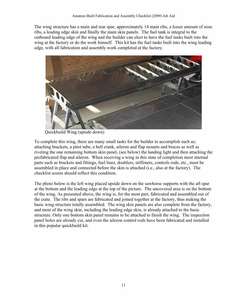
Wing Leading Edge
In the standard kit the leading edge is assembled from various component parts and attached to the wing. The builder also has to construct a cradle to assist in fitting the skin to the ribs.
W7 Fabricate Wing Leading/Trailing Edges 0.8 .02
W8 Assemble Wing Leading /Trailing Edges 0
1.0
The Wing leading edge components require trimming, deburring and updrilling. All internal parts (Fuel Tank, brackets) and external components must be assembled together. Builder receives all assembly credit in W8.
W9 Fabricate Drag/Antidrag Truss Members N/A --
W10 Assemble Drag/Antidrag Truss Mbrs N/A --
W11 Fabricate Wing Brackets and Fittings 0.8 .02
W12 Assemble Wing Brackets and Fittings 0 1.0
W11 and W12 follow the trend. Brackets and Fittings require finishing work usually and will be scored as such. Builder receives all assembly credit for attaching to the wing.
23

Amateur-Built Fabrication and Assembly Checklist (2009) Job Aid
A B C D
FABRICATION AND ASSEMBLY TASKS Mfr
Kit/Part/ Commercial
Am-Builder
Am-Builder
Component Assistance Assembly Fabrication
W13 Fabricate Wing Tips 0.9 0.1
W14 Assemble Wing Tips to Wing 0 1.0
W15 Fabricate Special Tools or Fixtures 1.0 0
In this instance, the scores for tasks W13 and W14 in the standard kit should be identical to the quick build kit components and assembly work. The builder receives the wing tips from the factory complete with only some trimming, and drilling to perform before attaching to the wing. In task W15, in the standard kit, the builder receives credit for building the wing cradles out of plywood, for assembling the wing leading edges and the main wing skin.
Aileron Spar with Counterbalance bar and end brackets
W16 Fabricate Aileron Spars .8 0.2
W17 Fabricate Aileron Ribs or Cores .8 0.2
The aileron spar is close to finished from the factory, needs some deburring, trimming and drilling to prepare for assembly. The stiffeners and 2 end ribs come mostly complete with the typical finish work of trimming, drilling and sanding, for the builder to apply.
24

Amateur-Built Fabrication and Assembly Checklist (2009) Job Aid
Aileron Skin with Internal Stiffeners Attached
A B C D
FABRICATION AND ASSEMBLY TASKS Mfr
Kit/Part/ Commercial
Am-Builder
Am-Builder
Component Assistance Assembly Fabrication
W18 Assemble Aileron Ribs/Cores to Aileron N/A --
W19 Assemble Aileron Primary Structure 0 1.0
W18 (See discussion for Quick build kit above). W19, builder receives all credit for assembling the aileron from supplied components. Alternatively, it would be acceptable to assign the credit for joining the ribs to the skin by putting the score in column “A” in task W18 and place the NA in column “A” in task W19. The important point here is to prevent a double credit occurring for a single application if both W18 and W19 were both assigned credit for this single function. It’s apparent from this example, that the complexity of the tax has a direct bearing on the methodology used to assign credits.
25

Amateur-Built Fabrication and Assembly Checklist (2009) Job Aid
W20 Fabricate Aileron Leading/Trailing Edge 0.8 .02
W21 Assemble Aileron Leading/Trailing Edge 0 1.0
This aileron has a true leading edge added to the front of the aileron that has to be assembled with some fabrication completed by the amateur builder. * Be aware that some simple metal flaps and ailerons in amateur-built kits do not have traditional leading/trailing edge structures. The components are small and do not require the same load bearing construction requirements as the wing itself, so no spars are used. The only internal structural components for these flight controls are several simple ribs with the skin providing the horizontal structural rigidity without a separate trailing edge. However you may want to consider the aileron gap fairing at this point and give the builder some credit for this task in the assembly task as represented above.
Aileron Brackets after trimming and drilling
W22 Fabricate Ailero Brackets and Fittings 0.8 0.2
W23 Assemble Aileron Brackets and Fittings 0 1.0
Identical to the Quick build kit. Aileron Brackets and Fittings need to be trimmed, drilled, deburred and riveted (assembled) in place.
26

Amateur-Built Fabrication and Assembly Checklist (2009) Job Aid
Aileron skin being joined to the aileron spar in task W25.
A B C D
FABRICATION AND ASSEMBLY TASKS
Mfr Kit/Part/ Commercial Am-Builder Am-Builder
Component Assistance Assembly Fabrication
W24 Fabricate Aileron Covering or Skin
0.8 0.2
W25 Assemble Covering or Skin to Aileron
0 1.0
The aileron skins are received mostly prefabricated, from the factory. The builder has some typical finishing work to accomplish before the skin can be joined to the internal components.
W26 and W27 N/A
W28 Assemble Aileron to Wing
0 1.0
A full assembly point is awarded to the builder for attaching the aileron to the wing.
Conventional Spar and Rib Construction. Traditional spar at top, bottom skin is folded at rear to form a faux rear spar providing an attach point for ribs trailing edge .
27

Amateur-Built Fabrication and Assembly Checklist (2009) Job Aid
A B C D
FABRICATION AND ASSEMBLY TASKS
Mfr Kit/Part/ Commercial Am-Builder Am-Builder
Component Assistance Assembly Fabrication
W29 Fabricate Flap Spars 0.8 0.2
W30 Assemble Flap Spars to Flap
N/A --
W31 Fabricate Flap Ribs or Cores
0.8 0.2
W32 Assemble Flap Ribs or Cores to Flap
N/A --
W33 Assemble Flap Primary Structure
0 1.0
Tasks W30 and W32 are problematic. Joining the flap spars and the ribs together is usually the functional assembly step in forming the basic (primary) flap structure. Technically speaking this means that before the spar and ribs are joined to form the basic structure no flap actually exists as seemingly implied in W30 and W32. It would have been more correct for the checklist to show that joining the ribs to the spar yields the flap primary structure (two fabrication tasks and one assembly task) and simply not listed assembly tasks W30 and W32. Also these tasks do not include the flap covering or skin which is contained in W36 and W37. The NKET team has dealt with this by frequently placing an N/A in tasks W30 and W32, and recognizing the assembly of the spar to the ribs as forming the primary structure in task W33, resulting in the scores shown above. Similar Example: A similar situation occurs in the Empennage section for the rudder and elevator. For example, look at the task group for tasks E44 - E48, the rudder section. This section is identical to the example as presented above for the flap tasks and could be treated in the same fashion. Again the checklist sequence has the spar and the ribs being assembled to the Rudder instead of directing that they be assembled together in one task producing the Rudder basic/primary structure. NKET has on occasion arrived at the following scores as shown below to reflect the actual assembly process of joining the spar the the ribs that forms the primary rudder structure:
FABRICATION AND ASSEMBLY TASKS
Mfr Kit/Part/
Commercial Am-
Builder Am-Builder
RUDDER Component Assistance Assembly Fabrication
E44 Fabricate Rudder Spar 1.0 0
E45 Assemble Rudder Spar to Rudder N/A
E46 Fabricate Rudder Ribs or Cores 1.0 0
E47 Assemble Rudder Ribs or Cores to Rudder
N/A
E48 Assemble Rudder Structure 0 1.0
Scoring the tasks in this fashion makes more sense and reflects the actual construction process.
28

Amateur-Built Fabrication and Assembly Checklist (2009) Job Aid
The flap on this aircraft does not have a conventional leading/trailing edge. The design extends the top flap skin past the spar in the front to cover the gap between the flap and wing. At trailing edge, the rear of the top skin folds down and under to overlap and then attach to the bottom skin.
A B C D
FABRICATION AND ASSEMBLY TASKS Mfr
Kit/Part/ Commercial Am-Builder Am-Builder
Component Assistance Assembly Fabrication
W34 Fabricate Flap Leading/Trailing Edges
N/A --
W53 Assemble Flap Leading/Trailing Edges
N/A --
Task W34 is N/A as explained in the caption above. More importantly, the checklist has an error, in that the expected assembly task that was supposed to follow W34 “Assemble Flap Leading Trailing Edge” was mistakenly omitted. It has been added here for purposes of illustration only. At time of evaluation it will have to be added to the checklist at the end of the section. On the most recent checklist it was added at W53. Likewise the next task Assemble Flap Brackets and Fitting is missing its Fabrication task. NKET has resolved this problem by adding these two missing tasks at the end of the Wings section at tasks W52 and W53.
29

Amateur-Built Fabrication and Assembly Checklist (2009) Job Aid
Piano Hinges Brackets
FABRICATION AND ASSEMBLY TASKS Mfr
Kit/Part/ Commercial Am-Builder Am-Builder
Component Assistance Assembly Fabrication
W52 Fabricate Flap Brackets/Fittings 0.8 .02
W35 Assemble Flap Brackets/Fittings to Flap
0 1.0
Flap Brackets and Fittings (includes hinges) need to be trimmed, drilled, deburred and riveted (assembled) in place. Include the hinge bracket in these tasks as well. W52 has been added to the checklist as an add item at the end of the wing section because it was mistakenly omitted.
30

Amateur-Built Fabrication and Assembly Checklist (2009) Job Aid
W36 Fabricate Flap Covering or Skin .08 0.2
W37 Assemble Flap Covering /Skin to Flap 0 1.0
The flap skins are received prefabricated, from the factory cut to the proper size and shape. Even the bends and folds on the front and aft part of the skin have been done. The builder has only the typical finishing work to accomplish before joining the skin to the basic structure. A B C D
FABRICATION AND ASSEMBLY TASKS Mfr
Kit/Part/ Commercial Am-Builder Am-Builder
Component Assistance Assembly Fabrication
W38 Assemble Flaps to Wing 0 1.0
The builder gets all the credit for assembling the flaps to the wings.
W39 Fabricate Wing External Lighting Components
*
W40 Assemble Wing External Lighting Components
0 1.0
Serious consideration is being given to recognizing the fabrication of these components as a non-checklist items and removing them from the checklist. Until that happens score appropriately.
W41 Assemble Basic Wing Structure N/A --
In half of the evaluations completed so far by the NKET, this task has received an “N/A.” The reason for this is by the time all the tasks prior to W41 have been completed, the Basic Wing Structure has already been assembled. The spars, ribs, leading and trailing edges, brackets, cables, etc., have all been assembled to form the Wing Primary structure. (For the aileron, task W19, Assemble Aileron Primary Structure, was used and W18 was “N/A.” For W 41, the reverse logic is applied.) The assembly of the primary structure for the wing occurs prior to reaching this point on the checklist and was assigned to the manufacturer.
31

Amateur-Built Fabrication and Assembly Checklist (2009) Job Aid
A B C D
FABRICATION AND ASSEMBLY TASKS Mfr
Kit/Part/ Commercial Am-Builder Am-Builder
Component Assistance Assembly Fabrication
W42 Fabricate Wing Fuel System Components
N/A --
W43 Assemble Fuel System Components to Wing
0 1.0
This does not include the fuel tank which is covered in tasks W49 and W50. It also does not cover the fuel lines which are covered in tasks W44 and W45. Tasks W42 and W43 refer to valves and pumps. Serious consideration is being given to recognizing the fabrication of these components as a non-checklist items but still keeping the assembly task so the builder can receive credit for installing them in the aircraft. NKET has been routinely assigning an “N/A” in the W42 task so the manufacturer is not penalized for providing this in a kit. W44 Fabricate Cables Wires and Lines .05 .05
W45 Assemble Cables Wires, Lines to Wing
0
1.0
The Cables, Wires and Lines tasks found in the checklist have a simple rule to follow for application of credit. “Cables carry a load, Wires transmit a current , and Lines have “flow” in that they carry a fluid or a gas.” For examples fuel “lines are lines because they have fluid flow. A Rudder control cable has a load or tension on it so it is a cable, but battery cables or wing tip electrical wires are wires because they transmit a current. In this kit the builder will have to manufacture some fuel lines, and complete some cables. The builder will have to assemble all cables, wires and lines to the aircraft.
W46 Fabricate Wing Covering or Skin 0.8 0.2
W47 Assemble Wing Covering or Skin to Wing
0 1.0
Task W46, the builder receives minimal credit for wing skin fabrication since the skin is measured, cut to correct size and shape with the pilot holes pre-drilled. Some trimming may be
32

Amateur-Built Fabrication and Assembly Checklist (2009) Job Aid
required and the holes have to be enlarged to the correct size for the rivet. Task W47 includes all the riveting of the skin to the wing basic structure. You may think the builder deserves more credit for these types of application, but bear in mind the processes occurring at the factory to deliver the skin in the exact size to fit to the aircraft. These include measuring the exact size of each skin panel, marking for the cuts, cutting the panel from raw stock. Then measuring again for accuracy and ensuring proper size. Then marking and setting the drill lines for the rivet holes and then drilling the holes. At the factory these processes may only take a few minutes on automated machines with the machine controls preset and a production run churning out multiple parts for several kits. If the builder had to perform the same processes without the aid of a modern machine shop with computer controlled applications, the work tasks would be increase significantly. W48 Fabricate Wing Struts/Wires N/A --
There are no wing struts or bracing wires on this aircraft. *Note: The attending assembly task for this item was inadvertently omitted from the checklist and must be annotated (if required) as an add item at the end of the section if required.
The outboard wing leading edge incorporates a fuel tank.
W49 Fabricate Fuel Tank N/A --
W50 Assemble Fuel Tank 0 1.0
The photos above taken of a standard build kit shows the internal components of the tanks that are actually integral to the outboard leading edge. The left photo shows an internal tank baffle which also serves as a rib and the right photo show an extra bulkhead that will seal the internal tank as it sits up against the spar. Additionally there are many stiffeners inside with a vent line and the installation of fuel caps as well. Add the sealant and other applications and it amounts to building a fuel tank instead of just dropping in a prefabricated tank and strapping it to the wing.
33

Amateur-Built Fabrication and Assembly Checklist (2009) Job Aid
FABRICATION AND ASSEMBLY TASKS Mfr
Kit/Part/ Commercial Am-Builder
Am-Builder
Component Assistance Assembly Fabrication
W51 Calibrate Fuel System Components N/A --
NKET does not consider task W51 to fit the definition of either an assembly or fabrication task and has decided that the task should receive an N/A. This item is slated for removal from the checklist at the next revision.
W52 Add item: Fabricate Flap Bracket and Fittings
Addressed Earlier, See W35
This task W52, was mistakenly omitted from the checklist and should have preceded task W35 on the checklist as the corresponding fabrication task.
W53 Add item: Assemble Flap Leading /Trailing Edges
Addressed Earlier See W34
Task W53 was mistakenly omitted from the checklist and should have followed task W34 on the checklist as the corresponding assembly task
W54 Add item: Assemble Wing Struts /Wires Addressed Earlier See W48
Task W54 was mistakenly omitted from the checklist and should have followed task W48 on the checklist as the corresponding assembly task
W55 Add item: Assemble Wing to Next Higher Structure
0 1.0
Task W55 was mistakenly omitted from the checklist.
The Fuselage (Metal) Another observation regarding the quick build kit, is the fuselage may be in a fairly advanced state of construction. Reviewing the kit builders’ manual should help to reveal the actual state of completeness. What can not be ascertained from this photo is whether or not the fuselage members, such as longerons, bulkheads, stringers, etc., are assembled to the fuselage skin, or just placed together to form the anticipated shape. These are questions to be answered by the builder and objective evidence such as a comprehensive builders log, pictures and the kit builder’s manual at time of inspection.
34

Amateur-Built Fabrication and Assembly Checklist (2009) Job Aid
Quick build Kit with Quick build Fuselage For example only, let’s assume that the fuselage in the photo above has the internal structural components provided as shown and that they are assembled and the skin is attached. Actually, for this particular quick build kit, that is exactly how the fuselage arrives to the builder. The kit components in the photo are strategically placed in proximity for marketing purposes and to increase sales. Let’s also assume through questioning and review of the builders log and pictures that the longitudinal members are fully formed, cut to size, and already joined to the bulkheads and formers i.e., assembled in place. Note: The firewall is usually considered to be part of the fuselage structure since it is in most instances the farthest forward bulkhead of the fuselage. However, in the Amateur-Built Fabrication and Assembly Checklist (2009), the firewall component will be considered and the points allocated in the Propulsion section.
Quick build Fuselage out of the crate.
Also, the bulkheads and formers were prefabricated and assembled into the fuselage as shown above with little of no finish work left to the builder. Finally the fuselage skin as shown is cut to size and actually riveted in place forming the semi-monocoque structure above. Obviously most of the work left to the builder will be finishing work. However, the builder may have to fabricate some angles, doublers and or cross members to complete the fuselage. All the forgoing is taken into consideration when awarding the points in tasks F1—F3, which may appear as such:
35
Amateur-Built Fabrication and Assembly Checklist (2009) Job Aid
A B C D
FABRICATION AND ASSEMBLY TASKS Mfr Kit/Part/ Commercial Am-
Builder Am-
Builder
Component Assistance Assembly Fabrication
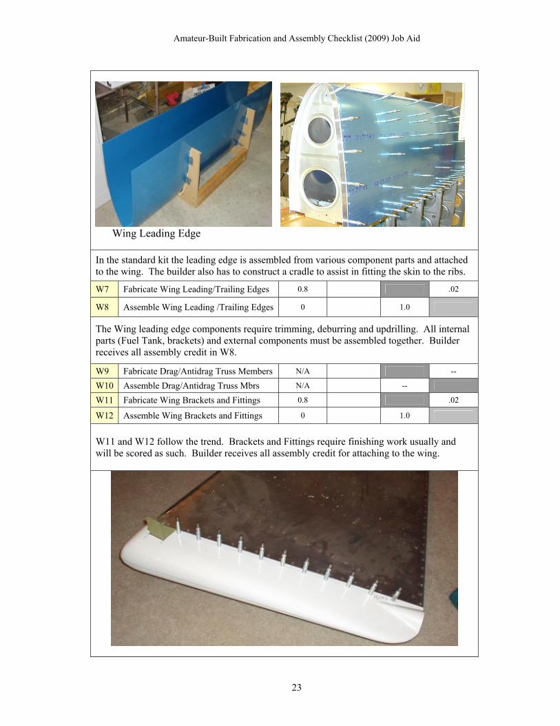
F1 Fabricate Longitudinal Members 1.0 0
F2 Fabricate Composite Cores or Shells, Skins
N/A --
F3 Fabricate Bulkheads or Cross Members 0.9 0.1
In F1, the stringers and longerons are prefabricated at the factory requiring the builder no finish work and a 0 for the builder would be appropriate for this task. For task F2, since this is an all metal aircraft, except for the composite wing tips and fiberglass cowling and wheel fairings, there are no internal composite parts, and an N/A is given.
Former, aft of the Cockpit. Tail Wheel Support Bulkhead. For F3, although the major bulkheads or formers were fabricated and assembled to the fuselage at the factory. A small amount of finish work was required to a few of the bulkheads and, during questioning and review of the builders log, you learn that the builder also had to drill, trim and debur the large former shown in the photo above. Add to that the bulkhead (tail wheel support) in the tail (photo on right) and the credit given to the builder comes in at a minimal 0.1 awarded for fabrication in the builder’s column D. Even this is a little generous for finish work on one former and one small bulkhead compared to the entire fuselage, but that is the smallest increment that can be awarded to recognize some work contribution by the builder or manufacturer. There have been occasions during an NKET visit that the team members have awarded no credit for some tasks, even though the builder did perform some small part of the fabrication, because the amount of work was too minimal to qualify for even a 0.1. The next tasks on the checklist, F4 - F7 provide a place for considering the aircraft operator control components and linkages to the flight control surfaces. Some aircraft have control cables under tension, some use push pull tubes, and some aircraft have a combination of both to operate their respective flight controls. Task group F4 - F7, can accommodate any of the system configurations listed above. While there is an argument to be made for including the aileron
36

Amateur-Built Fabrication and Assembly Checklist (2009) Job Aid
tubes or cables in the Wing section of the checklist, since all the control systems link up within the fuselage section, for simplicity sake it was decided to place them here in the fuselage section of the checklist. The control sticks come virtually complete with just some deburring and trimming to perform. Regarding the fabrication tasks, the actual amount of work left for the kit builder to accomplish in tasks F4 could be considered too minimal to receive any credit. Notice the evaluator awarded a 0.1 to the builder for the sticks and the full 1.0 credit for assembly to the aircraft.
FABRICATION AND ASSEMBLY TASKS Mfr Kit/Part/ Commercial Am-Builder Am-Builder
Component Assistance Assembly Fabrication
F4 Fabricate Control Yokes/Sticks 0.9 0.1
F5 Assemble Control Yokes/Sticks 0 1.0
Tasks F6 and F7 various cables and tubes provided in a prefabricated condition These aileron push tubes are provided in the kit. The builder is required to rivet the rod end onto the tubes (a fabrication task) that attach in the cockpit and go through the wing to connect at the bell crank. The control rods going out to the aileron come from the factory complete. There is an elevator pushrod as well that looks exactly like these aileron pushrods that must be riveted. For the rudder, this aircraft uses cables that attach to the rudder pedals in front, and travel rearward to a rudder horn as seen in the photo below.
37

Amateur-Built Fabrication and Assembly Checklist (2009) Job Aid
Rudder Cable attached to Rudder Horn
F6 Fabricate Flight Control Push Pull Tubes/Cables
0.8 0.2
F7 Assemble Flight Control Push Pull Tubes/Cables
0 1.0
For tasks F6 and F7, since there is some fabrication of the pushrod but no real fabrication on the cables, the credit for the builder is again minimal.
Standard Kit Large Bulkhead
For comparison sake, a central bulkhead from a standard kit is shown above, and several other formers are shown below. These components even though provided cut and sized by the factory, still require significant fabrication steps by the builder to be ready for installation in the aircraft.
38

Amateur-Built Fabrication and Assembly Checklist (2009) Job Aid
Standard Kit Fuselage structural members (formers)
Standard Kit Fuselage structure assembled
39
Amateur-Built Fabrication and Assembly Checklist (2009) Job Aid
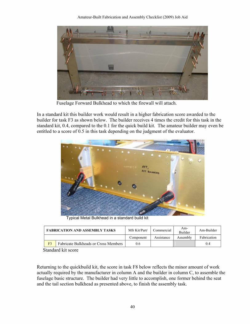
Fuselage Forward Bulkhead to which the firewall will attach.
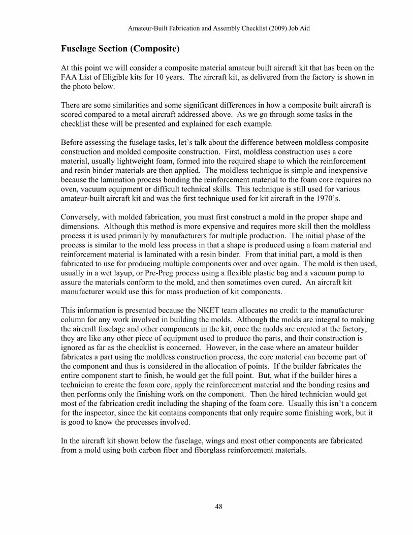
In a standard kit this builder work would result in a higher fabrication score awarded to the builder for task F3 as shown below. The builder receives 4 times the credit for this task in the standard kit, 0.4, compared to the 0.1 for the quick build kit. The amateur builder may even be entitled to a score of 0.5 in this task depending on the judgment of the evaluator.
Typical Metal Bulkhead in a standard build kit
FABRICATION AND ASSEMBLY TASKS Mfr Kit/Part/ Commercial Am-
Builder Am-Builder
Component Assistance Assembly Fabrication
F3 Fabricate Bulkheads or Cross Members 0.6 0.4
Standard kit score Returning to the quickbuild kit, the score in task F8 below reflects the minor amount of work actually required by the manufacturer in column A and the builder in column C, to assemble the fuselage basic structure. The builder had very little to accomplish, one former behind the seat and the tail section bulkhead as presented above, to finish the assembly task.
40

Amateur-Built Fabrication and Assembly Checklist (2009) Job Aid
A B C D
FABRICATION AND ASSEMBLY TASKS Mfr Kit/Part/ Commercial Am-Builder Am-Builder
Component Assistance Assembly Fabrication
F8 Assemble Fuselage Basic Structure 0.9 0.1
Quick build kit score The standard kit is a different matter. After the Longitudinal members (Stringers, Longerons) and bulkhead, formers and frame members are finished they can be joined together to form the basic fuselage structure. In the F8 assembly task shown below, the standard kit builder would receive all the assembly credit because the components are received in a partially unfinished state and must then be assembled by the builder entirely. Observe that the builder receives full assembly credit of 1.0 for this task.
F8 Assemble Fuselage Basic Structure 0 1.0
Standard kit score
For Tasks F9/10 - Brackets and Fittings, F11/12 - Cables Wires and Lines and F13/14 - Fuel System Components, see the respective tasks in the Wing section (at W11/12, W44/45, W42/43) above for methodology. The same concepts apply.
In task F15 (quick build) the situation is similar to the example provided in the Wing section at task W46 and W47. Since the quick build fuselage is over eighty percent complete from the factory, the builder has little opportunity to accumulate points.
Quick build Kit Fuselage out of the crate By reviewing the builder’s log (photo above) and questioning the builder you determine that the builder only has three panels to attach to the fuselage in order to complete the skin covering. The three panels are shown in the pictures below. The first one is the back strap panel on top of the fuselage directly behind the canopy, (notice the contour to accept the canopy). The other two panels are in front of the cockpit but behind the firewall. In the quick build kit, these are the only skin panels remaining to complete the F15 and F16 tasks.
41

Amateur-Built Fabrication and Assembly Checklist (2009) Job Aid
Fuselage Skin Quick build Kit
Fuselage Skin Quick build Kit
Since the builder only has some minor work to accomplish on both F15 and F16, the scores may appear as such:
A B C D
FABRICATION AND ASSEMBLY TASKS Mfr Kit/Part/ Commercial Am-
Builder Am-
Builder
F15 Fabricate Fuselage Covering or Skin .9 .1
F16 Assemble Fuselage Covering or Skin .9 0.1
Quick build Kit Score for Fuselage Skin
42

Amateur-Built Fabrication and Assembly Checklist (2009) Job Aid
The difference in the standard kit compared to the quickbuild is significant. All the individual components of the fuselage structure, i.e., longerons, bulkheads and braces as well as the skin, come as individual parts, disassembled as shown below.
The sheet metal skin panels provided in the kit for the fuselage are cut to the exact size and pre-drilled for their individual attach points. The builder still has to trim, debur and up drill and probably dimple the skin to prep for assembly to the basic fuselage structure. There will also be some reinforcement braces and stiffeners to drill and attach.
Skin panels being riveted in place on partially completed standard build fuselage structure. From the multiple rivet lines in this photo, numerous skin panels have to be prepared and attached to the fuselage structure, which trans-lates into significant work for the builder.
Standard build kit skin assembly The photo below shows a partially constructed fuselage structure with some bulkheads, braces and longerons in place. This photo gives an indication of how much assembly work is involved
43

Amateur-Built Fabrication and Assembly Checklist (2009) Job Aid
to obtain credit for just two assembly tasks, F8 and F16. F8 “Assemble “Fuselage Basic Structure,” includes joining all the bulkheads, internal longerons, stringers, angles, stiffeners, braces and spacers. Task F16 “Assemble Fuselage Covering or Skin” includes riveting all skin
panels to the fuselage structural components. This photo shows that the fuselage basic structure construction progresses in conjunction with the assembly of the skin in true semi-monocoque fabrication.
Aft Fuselage Section Standard Build Kit NOTE: Remember when riveting small subcomponents together, riveting is considered fabrication, and when attaching a major component to the aircraft structure (think wing or fuselage skins) riveting is considered assembly. As such riveting these fuselage skins to the frames and bulkheads would be considered assembly work.
Aft Fuselage Section Standard Build Kit In the standard build kit shown immediately above, the proper allocation of points for task F15 may be 0.7 or maybe even a 0.6 for the manufacturer and 0.3 or 0.4 for the builder. It’s a judgment call. In F16, the NKET has interpreted the checklist to mean attaching the skin to the
44

Amateur-Built Fabrication and Assembly Checklist (2009) Job Aid
fuselage to complete the structure. Of course for the standard build kit, the entire (full point) creditfor F16 goes to the builder.
A B C D
FABRICATION AND ASSEMBLY TASKS Mfr Kit/Part/ Commercial Am-
Builder Am-
Builder
Component Assistance Assembly Fabrication
F15 Fabricate Fuselage Covering or Skin 0.7/ 0.6 0.3/0.4
F16 Assemble Fuselage Covering or Skin 0 1.0
Standard Build Kit Score We will continue on with the standard build kit for scoring the rest of the fuselage. This aircraft does not have a windshield, so tasks F17 and F18 will be scored as N/A.
A B C D
FABRICATION AND ASSEMBLY TASKS Mfr Kit/Part/ Commercial Am-
Builder Am-
Builder
Component Assistance Assembly Fabrication
F17 Fabricate Windshield N/A --
F18 Assemble Windshield to Fuselage N/A --
F19 Fabricate Windows N/A --
F20 Assemble Windows to Fuselage N/A --
Standard Build Kit Score Task F19 and F20 should be scored an N/A. Do not include the small window behind the main canopy as a separate window. This component should be considered part of the main canopy system. The fabrication credit for the canopy will include the construction of the frame and apron to attach to the fuselage structure. Also include the hinge mechanism with latches and release hardware on the inside of the cockpit and fabrication of the metal frame.
45

Amateur-Built Fabrication and Assembly Checklist (2009) Job Aid
A B C D
FABRICATION AND ASSEMBLY TASKS Mfr Kit/Part/ Commercial Am-
Builder Am-
Builder
Component Assistance Assembly Fabrication
F21 Fabricate Doors/Canopy 0.6 0.4
F22 Assemble Doors/Canopy to Fuselage 0 1.0
Standard Kit Score
Luscombe aircraft with “Strut Assembly” from Fuselage to Wing The standard kit aircraft under consideration has no mast or strut assembly. A strut assembly is depicted in the high wing aircraft picture above. Thus tasks F23 and F24 are not applicable, (N/A).
F23 Fabricate Mast and Strut Assembly N/A --
F24 Assemble Mast and Strut Assembly N/A --
Standard Kit Score
46

Amateur-Built Fabrication and Assembly Checklist (2009) Job Aid
Rudder Pedals and Pivot Tubes
A B C D
FABRICATION AND ASSEMBLY TASKS Mfr Kit/Part/ Commercial Am-
Builder Am-
Builder
Component Assistance Assembly Fabrication
F25 Add item: Fabricate Rudder Pedals 0.8 0.2
F26 Add item: Assemble Rudder Pedals 0 1.0
Standard Kit Score
In order to assemble the rudder pedals to the inside of the fuselage, bushing blocks, brackets, stiffeners and angles are provided by the factory but the builder will need to drill, trim, and use fasteners to attach. For task F25, the finish work in either the quick build or the standard kit will be similar. The same holds true for task F26, where the builder of either kit will perform the entire task to assemble the rudder pedals and pivot tubes to which they are attached to the fuselage.
Composites and Other materials By now you should have a good understanding of the concepts involved and methodologies used to assess the task items in the wing and fuselage sections of the Amateur-built Fabrication and Assembly Checklist (2009). Also you should be able to use the criteria as presented in the wing section to effectively assess the tasks in the empennage section. This is true because credit allocation for the horizontal and vertical stabilizers and their attached flight control surfaces are analogous to evaluation of the wings, ailerons and flaps. This being the case, the guide will not go through the Empennage section step by step as presented above for the wings and the fuselage. Instead, we will now look at specific tasks throughout the entire checklist, as well as the Landing Gear, Propulsion and Cockpit sections, but not necessarily in that order. Also we will consider different construction materials such as composite and tube and fabric aircraft in the remaining pages and will review selected tasks that best illustrate unique assessment concepts and criteria both in sections previously covered and those not addressed as yet.
47
Amateur-Built Fabrication and Assembly Checklist (2009) Job Aid
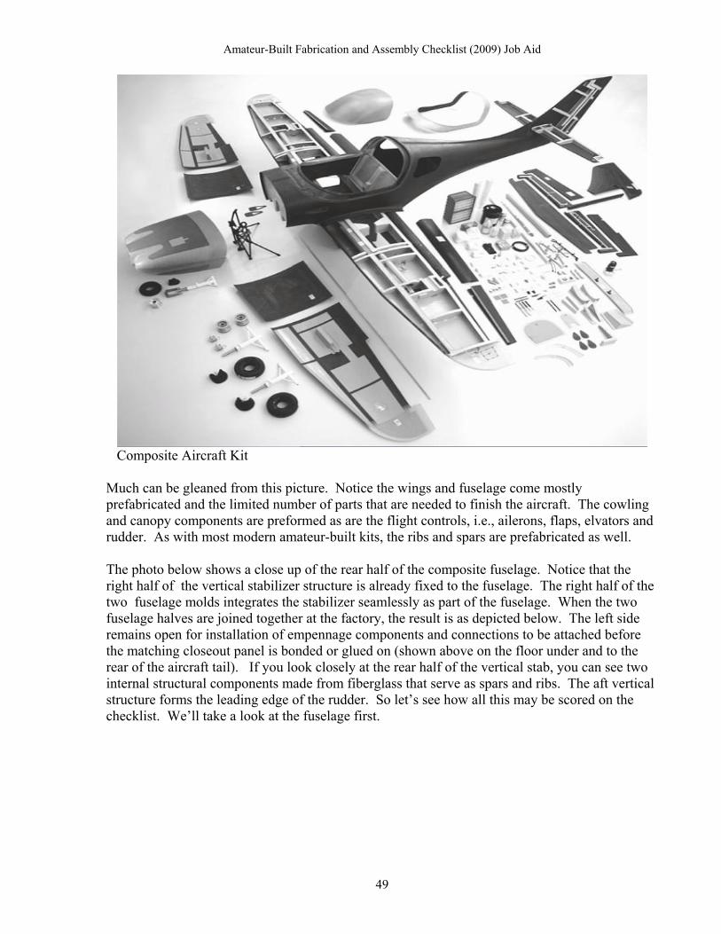
Fuselage Section (Composite) At this point we will consider a composite material amateur built aircraft kit that has been on the FAA List of Eligible kits for 10 years. The aircraft kit, as delivered from the factory is shown in the photo below. There are some similarities and some significant differences in how a composite built aircraft is scored compared to a metal aircraft addressed above. As we go through some tasks in the checklist these will be presented and explained for each example. Before assessing the fuselage tasks, let’s talk about the difference between moldless composite construction and molded composite construction. First, moldless construction uses a core material, usually lightweight foam, formed into the required shape to which the reinforcement and resin binder materials are then applied. The moldless technique is simple and inexpensive because the lamination process bonding the reinforcement material to the foam core requires no oven, vacuum equipment or difficult technical skills. This technique is still used for various amateur-built aircraft kit and was the first technique used for kit aircraft in the 1970’s. Conversely, with molded fabrication, you must first construct a mold in the proper shape and dimensions. Although this method is more expensive and requires more skill then the moldless process it is used primarily by manufacturers for multiple production. The initial phase of the process is similar to the mold less process in that a shape is produced using a foam material and reinforcement material is laminated with a resin binder. From that initial part, a mold is then fabricated to use for producing multiple components over and over again. The mold is then used, usually in a wet layup, or Pre-Preg process using a flexible plastic bag and a vacuum pump to assure the materials conform to the mold, and then sometimes oven cured. An aircraft kit manufacturer would use this for mass production of kit components. This information is presented because the NKET team allocates no credit to the manufacturer column for any work involved in building the molds. Although the molds are integral to making the aircraft fuselage and other components in the kit, once the molds are created at the factory, they are like any other piece of equipment used to produce the parts, and their construction is ignored as far as the checklist is concerned. However, in the case where an amateur builder fabricates a part using the moldless construction process, the core material can become part of the component and thus is considered in the allocation of points. If the builder fabricates the entire component start to finish, he would get the full point. But, what if the builder hires a technician to create the foam core, apply the reinforcement material and the bonding resins and then performs only the finishing work on the component. Then the hired technician would get most of the fabrication credit including the shaping of the foam core. Usually this isn’t a concern for the inspector, since the kit contains components that only require some finishing work, but it is good to know the processes involved. In the aircraft kit shown below the fuselage, wings and most other components are fabricated from a mold using both carbon fiber and fiberglass reinforcement materials.
48
Amateur-Built Fabrication and Assembly Checklist (2009) Job Aid
Composite Aircraft Kit Much can be gleaned from this picture. Notice the wings and fuselage come mostly prefabricated and the limited number of parts that are needed to finish the aircraft. The cowling and canopy components are preformed as are the flight controls, i.e., ailerons, flaps, elvators and rudder. As with most modern amateur-built kits, the ribs and spars are prefabricated as well. The photo below shows a close up of the rear half of the composite fuselage. Notice that the right half of the vertical stabilizer structure is already fixed to the fuselage. The right half of the two fuselage molds integrates the stabilizer seamlessly as part of the fuselage. When the two fuselage halves are joined together at the factory, the result is as depicted below. The left side remains open for installation of empennage components and connections to be attached before the matching closeout panel is bonded or glued on (shown above on the floor under and to the rear of the aircraft tail). If you look closely at the rear half of the vertical stab, you can see two internal structural components made from fiberglass that serve as spars and ribs. The aft vertical structure forms the leading edge of the rudder. So let’s see how all this may be scored on the checklist. We’ll take a look at the fuselage first.
49

Amateur-Built Fabrication and Assembly Checklist (2009) Job Aid
Rear Fuselage with integrated Vertical Stabilizer and attached Rudder
A B C D
FABRICATION AND ASSEMBLY TASKS Mfr
Kit/Part/ Commercial
Am-Builder
Am-Builder
Fuselage Section Component Assistance Assembly Fabrication
F1 Fabricate Longitudinal Members N/A --
F2 Fabricate Composite Cores or Shells, Skins 1.0 0
F3 Fabricate Bulkheads or Cross Members N/A --
For fuselage task F1, the internal strength and rigidity of the composite material used in fabricating the fuselage eliminates the need for traditional longitudinal members such as longerons and stringers and the task is usually given an “N/A” for composite aircraft. A composite fuselage is typically formed in two parts (two molds, left and right, or bottom and top) which are then bonded together at the factory so that it comes to the builder completely finished. The builder may have to do some minimal sanding for cosmetic purposes, but in most cases when the fuselage is fully formed and the manufacturer will receive a full point in column “A” and the builder will receive no credit for task F2. To emphasize this point, be advised that the builder manual for this aircraft kit does not even contain a fuselage section as one of its chapters. For task F3, there are no real bulkheads in the fuselage except the firewall which has its own task lines in the propulsion section. Just behind the cockpit section, there is a baggage compartment that has what is described in the manual as the “bulkhead cover” but it is not structural and is affixed with only some screw and nutplates, not bolts. Typically this situation would be scored with an “N/A” as shown above. This is a significant difference compared to all metal semi-monocoque construction.
50

Amateur-Built Fabrication and Assembly Checklist (2009) Job Aid
The Control Yokes and Push Pull Tube tasks are not significantly different from the all metal aircraft. Please refer to tasks F4 – F7 in the previous section for their analysis.
FABRICATION AND ASSEMBLY TASKS Mfr
Kit/Part/ Commercial
Am-Builder
Am-Builder
F8 Assemble Basic Fuselage Structure 0.9 0.1
In the scoring of task F8, since the two halves of the fuselage are joined at the factory to ensure proper bonding, almost all of the credit goes to the manufacturer in column “A.” The builder may have some residual finish work to perform, but certainly not more than a 0.1 or 0.2 credit.
For Tasks F9/10 Brackets and Fittings, F11/12 Cables Wires and Lines and F13/14 Fuel System Components, see the respective tasks in the Wing section (at W11/12, W44/45, W42/43) above for methodology. The same concepts apply.
FABRICATION AND ASSEMBLY TASKS Mfr
Kit/Part/ Commercial
Am-Builder
Am-Builder
F15 Fabricate Fuselage Covering or Skin N/A --
F16 Assemble Fuselage Covering or Skin N/A --
F17 Fabricate Windshield N/A --
F18 Assemble Windshield to Fuselage N/A --
On a composite aircraft the fuselage skin is integral to the fuselage structure and is not separate like a metal or fabric skin. Thus, tasks F15/F16 are scored “N/A.” Also, this aircraft does not have a windshield and F17 and F18 will be scored “N/A” as well.
There are two fuselage window just behind the cockpit. Both are framed and fit to plexiglass. At least one has a hinge and latch mechanism for opening into the baggage area. The frames are cut and shaped by the manufacturer but require trimming, sanding, and bonding on both windows by the builder to complete the fabrication process. The scores may appear as such below.
FABRICATION AND ASSEMBLY TASKS Mfr
Kit/Part/ Commercial
Am-Builder
Am-Builder
F19 Fabricate Windows 0.6 or 0.7 0.4 or 0.3
F20 Assemble Windows to Fuselage 0 1.0
51

Amateur-Built Fabrication and Assembly Checklist (2009) Job Aid
Canopy Bubble and Frame
FABRICATION AND ASSEMBLY TASKS Mfr
Kit/Part/ Commercial
Am-Builder
Am-Builder
F21 Fabricate Doors/Canopy 0.5 .05
F22 Assemble Doors/Canopy to Fuselage 0 1.0
The canopy bubble and frame comes preformed with the kit. Again, like the window, the canopy bubble must be bonded to the frame and requires cutting, sanding, trimming and bonding. It is more work then appears in the pictures above. NKET has typically given anywhere from a 0.3 to a 0.6 to the builder for this fabrication task. While it is a judgement call, something close to splitting the credit equally between the builder and the manufacturer is a good starting point.
A B C D
FABRICATION AND ASSEMBLY TASKS Mfr Kit/Part/ Commercial Am-
Builder Am-
Builder
Component Assistance Assembly Fabrication
F23 Fabricate Mast and Strut Assembly N/A --
F24 Assemble Mast and Strut Assembly N/A --
F23 and F24 are NA (do not exist) on this aircraft
F25 Add item: Fabricate Rudder Pedals 0.8 0.2
F26 Add item: Assemble Rudder Pedals 0 1.0
Depending on the plans and actual application of work, the credit given to the builder for the rudder pedals may be higher or lower then presented here. Wings (Composite) Let’s move on to the Wing section to demonstrate the score application for a totally different model of composite kit. This section will be present selected tasks such as the, ribs/cores, ailerons, skin and flaps. Recall the discussion above about the composite construction dealing with components made with molds versus mold less construction. The pictures below represent the type of foam parts that a builder would receive in a kit using the mold less process.
52

Amateur-Built Fabrication and Assembly Checklist (2009) Job Aid
The foam material for the individual aircraft components may come out of the box like this photo to the left, in which case the builder would have to cut and shape the foam into the correct finished contour and form. Most composite kits provide the type of foam cores as shown below, with the foam cores properly shaped and sized, ready for application of fiberglass cloth and resin.
Foam (core) part for wing leading edge Foam central wing rib unlaminated Some of these preformed and shaped parts will still need to be cut and trimmed before being covered with epoxy resin and fiberglass cloth to complete the process. Until the composite materials are applied and cured these shapes remain fragile and have zero strength or load capability. Afterwards however, they can become as rigid and as strong as a wing made from other conventional materials, sometimes stronger. In composite wing construction, the main spar is very often made of wood. The spar also can be fiberglass. If the spar is composite material it will be built up with many layers of fiberglass cloth and resin until the proper thickness for load bearing is reached. The proper scores for the wing main ribs and the leading edge components as depicted in the photos above, are applied to the checklist below.
53

Amateur-Built Fabrication and Assembly Checklist (2009) Job Aid
A B C D
FABRICATION AND ASSEMBLY TASKS Mfr Kit/Part/ Commercial Am-
Builder Am-
Builder
Component Assistance Assembly Fabrication
W3 Fabricate Wing Ribs or Cores 0.4 .06
W4 Assemble Wing Ribs or Cores to Wing 0 1.0
The wing ribs and leading edge cores were cut, shaped and formed at the factory. However, that does not the complete rib fabrication task which requires the resin and fiberglass overlay, and is labor intensive. So the amount of work to complete this task is heavily biased to the builder. This type of foam construction is different from that presented below. These foam parts are separate components to be placed inside the wing’s internal empty space like standard metal or wood ribs. The method shown below is entirely different in that the foam core is formed in the shape of a wing and then the entire shape is laminated with fiberglass and resin without separate internal components. As usual, the builder receives all the assembly credit.
In a variation of the composite construction methods for the wing, the builder does not fabricate individual ribs but shapes a foam core of the entire wing and then attaches it to a spar as shown below. The scoring for this process is different.
Wing Foam Core mated to carbon fiber spar With the above photo of the wing foam core in mind, let’s consider the wing section tasks immediately affected. The assumptions are; that the builder received the spar from the factory in a complete and fully formed condition, that the foam core seen above was provided properly shaped and formed, that the builder attached the two foam cores (wing shape front and rear) to
54

Amateur-Built Fabrication and Assembly Checklist (2009) Job Aid
the spar, and that the aileron and flap shapes will be cut from the foam core shape after the hard laminate covering is applied.
A B C D
FABRICATION AND ASSEMBLY TASKS Mfr Kit/Part/ Commercial Am-
Builder Am-
Builder
Component Assistance Assembly Fabrication
W1 Fabricate Wing Spars 1.0 0
W2 Assemble Wing Spars to Wing 0 1.0
The wing spars were fabricated in total at the factory. As usual, the builder receives all the assembly credit for joining the spars to the wing.
W3 Fabricate Wing Ribs or Cores N/A --
W4 Assemble Wing Ribs or Cores to Wing N/A --
These two tasks are not applicable. The internal structure of the wing is all one foam core to be captured in the following tasks W5 and W6.
W5 Fabricate Composite Cores 1.0 0
W6 Assemble Composite Cores to Wing 0 1.0
The wing foam cores were cut, shaped and formed at the factory and delivered to the builder in the condition as seen in the photo. The cores were joined to the spars by the builder and are then ready to receive the overlay of fiberglass and resin which will be captured in W46 and S47. As usual, the builder receives all the assembly credit.
W7 Fabricate Wing Leading and Trailing Edges
0.6 0.4
W8 Assemble Wing Leading & Trailing Edges to Wing
0 1.0
The wing leading and trailing edges are most likely intergral to the wing structure as formed at the factory and then covered with laminate by the builder. Occasionally in this type of construction, a separate and unique component is applied to the wing structure such as a metal or composite straight bar laminated into place to form the wing trailing edge. For example, after the laminate is applied and hardens to the wing, typically the flap and aileron shapes are cut from the wing shapes. This leaves an exposed foam core at the trailing edge of the wing that must be covered with a hard material. In some cases a conforming sheet metal plate is laminated in place to form a hard trailing edge, or just several layers of additional fiberglass and resin laminate is applied, depending on the strength requirements and design. In either case, the builder receives some of the credit for fabrication and all the credit for assembly. In this case, assume that a sheet metal insert is received from the factory and requires cutting, trimming and sanding to prepare for use. Then the scores would be as presented above.
W46 Fabricate Wing Covering or Skin 0 1.0
W47 Assemble Wing Covering or Skin to Wing
0 1.0
55
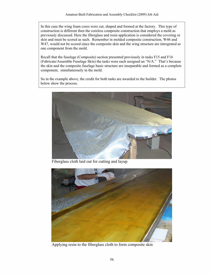
Amateur-Built Fabrication and Assembly Checklist (2009) Job Aid
In this case the wing foam cores were cut, shaped and formed at the factory. This type of construction is different then the coreless composite construction that employs a mold as previously discussed. Here the fiberglass and resin application is considered the covering or skin and must be scored as such. Remember in molded composite construction, W46 and W47, would not be scored since the composite skin and the wing structure are intregrated as one component from the mold. Recall that the fuselage (Composite) section presented previously in tasks F15 and F16 (Fabricate/Assemble Fuselage Skin) the tasks were each assigned an “N/A.” That’s because the skin and the composite fuselage basic structure are inseparable and formed as a complete component, simultaneously in the mold. So in the example above, the credit for both tasks are awarded to the builder. The photos below show the process.
Fiberglass cloth laid out for cutting and layup
Applying resin to the fiberglass cloth to form composite skin
56

Amateur-Built Fabrication and Assembly Checklist (2009) Job Aid
If the flaps are constructed with the same process as the wing, i.e., a foam core is shaped and then a fiberglass skin is applied the scores may appear as shown below:
A B C D
FABRICATION AND ASSEMBLY TASKS Mfr Kit/Part/ Commercial Am-
Builder Am-
Builder Component Assistance Assembly Fabrication
W29 Fabricate Flap Spars N/A --
W30 Assemble Flap Spars to Flap N/A
A flap spar is not usually required for small composite aircraft since the fiberglass skin is sufficiently rigid and strong without one.
W31 Fabricate Flap Ribs or Cores 0.2 0.8
W32 Assemble Flap Ribs or Cores to Flap 0 1.0
As in the wing tasks, the flap cores are cut and shaped by the kit manufacturer and the builder trims and sands the foam before proceeding. In W32, the main wing core (in two parts) is attached to the main and rear spar prior to proceeding.
W33 Assemble Flap Primary Structure N/A --
Strictly speaking there is no conventional primary structure of spar and ribs in this type of flap construction. The foam core is cut and shaped which is captured in W31 and W32, and then is laminated with the fiberglass cloth and resin to make the skin (W36). The laminate provides all the required structural rigidity.
W34 Fabricate Flap Lead & Trailing Edges N/A --
There is no separate component for a leading edge. Score is N/A.
W35 Assemble Flap Brackets & Fittings to Flap
0 1.0
The brackets are usually provided in the kit and the builder usually attaches them to the flap.
W36 Fabricate Flap Covering or Skin 0 1.0
W37 Assemble Flap Covering or Skin to Flap
0 1.0
This process is identical to that described in W46 and W47 in the previous section.
W38 Assemble Flaps to Wing 0 1.0
Attach the flap to the wing in final assembly process. Credit to the builder.
W53 Add item: Assemble Flap Leading & Trailing Edges
N/A --
This task (W53) is the reciprocal assembly task to W34 and is scored N/A
W54 Add item: Fabricate Flap Brackets & Fittings.
1.0 0
This task (W54) is the reciprocal fabrication task to W35 and is scored 1.0 for the kit manufacturer.
The builder should have lots of pictures like those below, to provide evidence that the aircraft was amateur-built. These photos also to provide information in conjunction with the builder’s log of how the tasks were accomplished and how much of the fabrication and assembly was performed by the builder and how much at the factory.
57

Amateur-Built Fabrication and Assembly Checklist (2009) Job Aid
Center wing section, composite construction, fabricated in a mold at the factory. All materials, spar, ribs, formers are all made out of composite material.
Empennage section photos Various Wood Parts Examples A typical wood aircraft uses ribs, fuselage frame structure and other components built from wood and then covered with fabric. One drawback to building with wood is that it takes longer then metal or composite construction. The popularity of aluminum and composites in amateur-
58

Amateur-Built Fabrication and Assembly Checklist (2009) Job Aid
built aircraft kits stems from their ease of construction but some builders still elect to use wood and one or two wood kits are still available. One little known fact is that the de Havilland Mosquito, a WWII twin engine British fighter, was made almost entirely out of wood in furniture factories in England and Canada.
de Havilland Mosquito Bomber
Examples of amateur-built aircraft kits constructed with wood framing are mostly vintage designs built from plans such as the Volksplane, the Sky Scooter and the Baby Lakes. Another aircraft, the Sequoia Falco is all wood. Even the Rand KR-1 which is considered a composite aircraft uses a wood frame structure. Some aircraft use a steel tube fuselage frame and wood construction for the wing (Wittman Tailwind) and empennage components (ribs and spars) and then covers it all in fabric. When building a wood aircraft from plans or a kit, there should be lots of pictures like these:
59

Amateur-Built Fabrication and Assembly Checklist (2009) Job Aid
Bulkhead
Former
Leading edge rib
60

Amateur-Built Fabrication and Assembly Checklist (2009) Job Aid
Spar and leading edge rib joining In the example below, these wood wing ribs are fabricated by the builder from raw materials using a jig constructed from a set of plans (template) from the manufacturer.
Ailerons constructed from plans and raw materials using a template/jig An amateur builder can provide a picture such as shown above to prove that the ribs were made from raw materials and thus deserves the entire credit of a 1.0 in the W3 task. The entry would appear as such below:
A B C D
FABRICATION AND ASSEMBLY TASKS Mfr
Kit/Part/ Commercial
Am-Builder
Am-Builder
Component Assistance Assembly Fabrication
W3 Fabricate Wing Ribs or Cores 0 1.0
W4 Assemble Wing Ribs or Cores to Wing 0 1.0
61
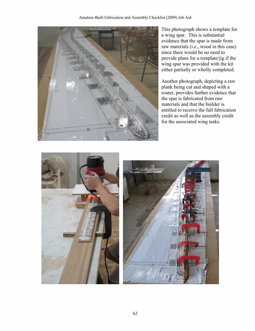
Amateur-Built Fabrication and Assembly Checklist (2009) Job Aid
This photograph shows a template for a wing spar. This is substantial evidence that the spar is made from raw materials (i.e., wood in this case) since there would be no need to provide plans for a template/jig if the wing spar was provided with the kit either partially or wholly completed. Another photograph, depicting a raw plank being cut and shaped with a router, provides further evidence that the spar is fabricated from raw materials and that the builder is entitled to receive the full fabrication credit as well as the assembly credit for the associated wing tasks.
62

Amateur-Built Fabrication and Assembly Checklist (2009) Job Aid
Partially finished Wing Spar
Completed Wing Spar
A B C D
FABRICATION AND ASSEMBLY TASKS Mfr
Kit/Part/ Commercial
Am-Builder
Am-Builder
Component Assistance Assembly Fabrication
W1 Fabricate Wing Spars 0 1.0
W2 Assemble Wing Spars to Wing 0 1.0
Full credit for both fabrication and assembly tasks awarded to builder from photo evidence. The string of photos showing the fabrication process in successive levels of construction is the best evidence of a completed component.
63

Amateur-Built Fabrication and Assembly Checklist (2009) Job Aid
Wood Kit Wing and Empennage Components prefabricated at factory. The photograph above showing component parts received from the manufacturer, shows that a wood kit can be similar to a metal aircraft kit that has a great many individual components provided by the manufacturer. These wing and empennage ribs and may be delivered to the builder in the above state and may in fact require less finishing work then a metal part prior to assembly. Sample scores for this scenario are presented below:
A B C D
FABRICATION AND ASSEMBLY TASKS Mfr
Kit/Part/ Commercial
Am-Builder
Am-Builder
Component Assistance Assembly Fabrication
W3 Fabricate Wing Ribs or Cores 0.8 0.2
W4 Assemble Wing Ribs or Cores to Wing 0 1.0
Task W5 and W6 below are obviously N/A for wood construction.
W5 Fabricate Composite Cores N/A
W6 Assemble Composite Cores to Wing N/A
Fuselage Components (Wood)
In the case of the bulkheads in the Fuselage section, pictures such as those below would be essential in providing evidence if the builder claims that the component was constructed from raw materials.
64

Amateur-Built Fabrication and Assembly Checklist (2009) Job Aid
Here, the bulkhead is in an almost finished state, with just a few more braces needed for completion. With this photo and the photo above, the builder has some evidence to support the fabrication and assembly claims. However, these two photos don’t prove that the internal components were fabricated from raw stock. The internal framing parts could have been included in the kit and the evaluator should pose the question on whether
that is indeed the case if photos are not provided. It would be much better to have severaof the bulkhead cross members being fabricated or to show that they were provided partially complete in a kit. For purposes of this manual lets assume that the internal framing was providedin a kit and needed cutting, trimming, sanding and gluing to complete the component. The score for task F3 may appear a
l shots
s such:
A B C D
FABRICATION AND ASSEMBLY TASKS Mfr Kit/Part/ Commercial Am-
Builder Am-
Builder
Component Assistance Assembly Fabrication
F3 Fabricate Bulkheads or Cross members 0.7 0.3
The photos below represent a wood fuselage structure. This is evidence that the amateur builder assembled the fuselage but not proof that the individual components, i.e., gussets, cross bracing, longerons and bulkheads were actually fabricated from raw materials. All the individual components could have been provided in a kit and the photos below do not refute this. The start point must be known prior to beginning the evaluation. Is this a plans built or kit built aircraft project? The scores for tasks F1, F3, and F8 follow.
Fuselage side structure with truss cross bracing and gussets for strengthening
65

Amateur-Built Fabrication and Assembly Checklist (2009) Job Aid
Basic wood fuselage internal structure
A B C D
FABRICATION AND ASSEMBLY TASKS Mfr Kit/Part/ Commercial Am-
Builder Am-
Builder
Component Assistance Assembly Fabrication
F1 Fabricate Longitudinal Members 0 1.0
F3 Fabricate Bulkheads or Cross members 0 1.0
F8 Assemble Fuselage Basic Structure 0 1.0
These scores represent an amateur builder constructing a fuselage structure and bulkhead from from plans using raw materials with no commercial assistance. (Yes, it’s still done.) If the basic components are provided in a kit and require only finish work, the scores for F1 and F3 would be much different. Photos showing fabrication of individual parts is required to award credit .
Steel Tube Fuselage prefabricated at the factory.
66

Amateur-Built Fabrication and Assembly Checklist (2009) Job Aid
A B C D
FABRICATION AND ASSEMBLY TASKS Mfr Kit/Part/ Commercial Am-
Builder Am-
Builder
Component Assistance Assembly Fabrication
F1 Fabricate Longitudinal Members 1.0 0
F3 Fabricate Bulkheads or Cross members 1.0 0
F8 Assemble Fuselage Basic Structure 1.0 0
These scores represent a steel tube fuselage structure used in many amateur built aircraft kits that come completely put together as shown. This is a common and popular type of construction produced by many of the companies marketing airplanes that resemble the old Piper Cub from the 1930s and 40s. In this case, there is virtually nothing for the amateur builder to fabricate or assemble. The entire welded structure is delivered with the kit as shown above. Sometimes the structure requires some filing and deburring which would result in a tenth (0.1) of a point for the builder in tasks F1 and F3. For task F8, the builder would receive no credit for this aircraft type.
Scores for Steel Tube fuselage fabricated and assembled at the factory
This photo shows horizontal stabilzer parts as provided by the factory.
As such the builder will receive minor credit for fabrication.
Mfr Kit/Part/
Commercial Am-
Builder Am-Builder FABRICATION AND ASSEMBLY
TASKS Component Assistance Assembly Fabrication
EMPENNAGE A B C D
E1 Fabricate Horizontal Stabilizer Spars 0.8 0.2
E2 Assemble Horiz/Stab Spars to Stabilizer N/A -
E3 Fabricate Horizontal Stab Ribs or Cores 0.8 0.2
E4 Assemble Horiz/StabRibs or Cores to Stabilizer
N/A -
E9 Assemble Horizontal Stabilizer Structure
0 1.0
67

Amateur-Built Fabrication and Assembly Checklist (2009) Job Aid
Tasks E2 and E4: Joining the Horz/Stabilizer spars and the ribs together is usually the functional assembly step in forming the basic (primary) structure. Technically speaking this means that before the spar and ribs are joined to form the basic structure no Horz/Stabilizer structure actually exists as implied in tasks E2 and E4. It would have been more correct for the checklist to show that joining the ribs to the spar yields the primary structure (two fabrication tasks and one assembly task) and simply not listed assembly tasks E2 and E4. Also these tasks do not include the covering or skin which is contained in E14 and E15. The NKET team has dealt with this by frequently placing an N/A in tasks E2 and E4, and recognizing the assembly of the spar to the ribs as forming the primary structure in task E10, resulting in the scores shown above.
Empennage Section Rudder Basic Structure In the photos depicted above, the basic structures are presented in an assembled state. If there is no other photo evidence to prove fabrication of the ribs, leading edge and spars, the evidence would be insufficient to award full fabrication credit to the builder because there is no photos of the individuals components state of construction. If the aircraft is being constructed from plans and not a kit, then other photographic evidence of the components should be available. Photographs such as those below, show various componets being fabricated from raw stock and deserve to be fully credited to the builder in the fabrication task line.
68

Amateur-Built Fabrication and Assembly Checklist (2009) Job Aid
69

Amateur-Built Fabrication and Assembly Checklist (2009) Job Aid
Mfr Kit/Part/
Commercial Am-
Builder Am-Builder FABRICATION AND ASSEMBLY
TASKS Component Assistance Assembly Fabrication
EMPENNAGE A B C D
E44 Fabricate Rudder Spar 0 1.0
E45 Assemble Rudder Spar to Rudder N/A
E46 Fabricate Rudder Ribs or Cores 0 1.0
E47 Assemble Rudder Ribs or Cores to Rudder
N/A
E48 Assemble Rudder Structure 0 1.0
For the task group E44 - E48, the rudder section is identical to the example as presented above for the Horz/Stabilizer tasks and could be treated in the same fashion. Again the checklist sequence has the spar and the ribs being assembled to the rudder instead of directing that they be assembled together in one task producing the rudder primary structure. NKET has scored the rudder tasks to reflect the actual assembly process of joining the spar the the ribs to forms the primary rudder structure in E48.
Propulsion Section
A typical metal firewall, tasks P28 and P29 on the checklist, as shown below, would, in conventional aircraft construction may be considered a forward bulkhead and thus part of the fuselage structure. However, since the firewall is such a crucial safety item, that ensures separation of the cockpit from the engine and exhaust system, the firewall has been placed in the propulsion section of the checklist. Also it fits in this section when considering and assessing all the components that attach to and run through the firewall coming from the engine.
� The firewall with angles, stiffeners, brackets and gussets clecoed in place for final riveting. The builder was required to cut and drill some of the braces and angles and then had to cut the square hole in the center. Finally he had to rivet all the parts together to make the finished firewall component seen in the photo to the left.
70

Amateur-Built Fabrication and Assembly Checklist (2009) Job Aid
Mfr Kit/Part/
Commercial Am-
Builder Am-
Builder FABRICATION AND ASSEMBLY TASKS Component Assistance Assembly
Fabrication
EMPENNAGE A B C D
P28 Add item: Fabricate Engine Mounts 0.4 .06
P29 Add item: Assemble Engine Mounts to Next Level Structure
0 1.0
As indicated above these tasks were added to the checklist to account for a major structural component that had inadvertently been omitted from the checklist. In this kit, the builder was provided with a piece of sheet metal roughly cut to size. The builder had to rivet in place all the stiffners, angles, gussets. Cut and trim the sheet metal to the proper shape and also cut a rectangular hole cut in the middle as shown above. Remember, riveting small sub-components together is fabrication work. Thus the scores as shown above.
In almost every case, regardess of the aircraft type and materials, the engine mounts are either included with the kit or purchased on the market by the builder. Very seldom does the builder fabricate this item from steel tubing from scratch. The builder receives full credit for assembly
Engine Mount
Mfr Kit/Part/
Commercial Am-
Builder Am-Builder FABRICATION AND ASSEMBLY
TASKS Component Assistance Assembly Fabrication
P1 Fabricate Engine Mounts 1.0 0
P2 Assemble Engine Mounts to Next Level Structure
0 1.0
71

Amateur-Built Fabrication and Assembly Checklist (2009) Job Aid
Baffles
The sheet metal components provided for the baffle/cooling system, are cut, drilled and shaped to size by the manufacturer. The builder is required to trim, debur and rivet (fabrication) the components together and then install (assembly) the baffle system to the engine and firewall.
A B C D
FABRICATION AND ASSEMBLY TASKS Mfr Kit/Part/ Commercial Am-Builder Am-Builder
Component Assistance Assembly Fabrication
P3 Fabricate Engine Cooling System/Baffles 0.5 0.5
P4 Assemble Engine Cooling System Baffles to Engine
0 1.0
P5 Fabricate Engine Compartment Overheat/Fire Detection System
1.0 0
P6 Assemble Overheat/Fire Detection System to Engine Compartment
0 1.0
If the aircraft has this system, P5 and P6, it most likely will be obtained from the engine manufacturer and the credit for fabrication would go to the manufacturer. The assembly credit most likely goes to the builder.
P7 Fabricate Induction System TBD ?
P8 Assemble Induction System to Engine TBD
?
Same application as P5 and P6 if present, however, depending on configuration and materials the builder may get substantial fabrication credit if forming the air induction system into the cowling out of composite or sheet metal. Score appropriately from personal observation.
P9 Fabricate Exhaust System 1.0 0
P10 Assemble Exhaust System to Engine 0 1.0
72

Amateur-Built Fabrication and Assembly Checklist (2009) Job Aid
In almost every kit, regardless of type of aircraft or construction materials the engine exhaust is most often purchased from the engine manufacturer. Very seldom does the builder fabricate this item from scratch. The builder receives full credit for assembly.
A B C D
FABRICATION AND ASSEMBLY TASKS Mfr Kit/Part/ Commercial Am-Builder Am-Builder
Component Assistance Assembly Fabrication
P11 Fabricate Engine Control Installation Brackets
0.8 0.2
P12 Assemble Engine Controls To Next Level Structure
0 1.0
The Engine Control Bracket task refers just to the brackets. The actual engine controls such as the FADEC, throttle, carb heat, etc., are non-checklist items and may be purchased without penalty from the engine manufacturer. Here we are only referring to the brackets. If they are provided pre-fabricated by the engine manufacturer then all the credit will go in the manufacturers column. In most cases the builder will get partial fabrication credit for drilling, trimming and deburring. Most likely the builder will receive all the assembly credit as depicted above.
P13 Rig and Adjust Engine Controls N/A --
The NKET has determined that the task P13 is neither fabrication or assembly in the strict sense of the terms and should not be accorded credit separately. The requirement to ensure that the engine operates and functions properly and is safe for flight is not awarded credit on the checklist.
P14 Fabricate Brackets and Fittings 0.8 0.2
P15 Assemble Brackets and Fittings to Next Level Structure
0 1.0
These tasks include all brackets and fittings in the engine compartment except the those as represented in tasks P11 and P12 engine controls. Most often the manufacturer will provide the brackets in a semi-completed state and the builder will assemble them to the aircraft/engine as shown above.
73

Amateur-Built Fabrication and Assembly Checklist (2009) Job Aid
A B C D
FABRICATION AND ASSEMBLY TASKS Mfr Kit/Part/ Commercial Am-Builder Am-Builder
Component Assistance Assembly Fabrication
P16 Fabricate Cables, Wires and Lines .5 .5
P17 Assemble Cables, Wires and Lines to Next Level Structure
1.0 0
Usually the manufacturer provide the cables, wires and lines in some state of completion. Some provide raw material, others the finished component. Either way the builder will usually have to furnish some level of work to complete the fabrication. The builder usually, except in some quickbuild kits, will perform the assembly task and get all the credit.
P18 Assemble Engine (Likely N/A) N/A -
There are several engine manufacturers that offer the option to assemble an engine from all the manufactured components. Aero Vee and Eagle Engines come to mind. The vast majority of kit builders do not choose this option.
P19 Assemble Engine to Engine Mount 0 1.0
Usually the builder performs this task and receives full credit.
P20 Fabricate Engine Propeller (Likely N/A)
N/A --
P21 Fabricate Propeller Spinner Components
1.0 0
P22 Assemble Propeller to Engine 0 1.0
Task P20 is usually scored as N/A, however, some very technically astute mechanics have been known to fabricate their own propellers. If so, then they can receive the credit. (This task is under consideration for removal, since it is designated in FAA Order 8130.2 as a non-checklist item and does not impact the builder. Task P21 is provided in most cases by the engine manufacturer. If so, score as above and modify with minor credit if required. Usually the builder performs task P22. (Includes assembly of the spinner to the hub) P23 Rig and Track Propellr N/A --
P23 is neither fabrication or assembly and receives no credit. The NKET has determined that this function is part of the normal requirement to ensure that all systems are operating correctly and should not be considered for awarding credit for the builder or manufacturer.
74
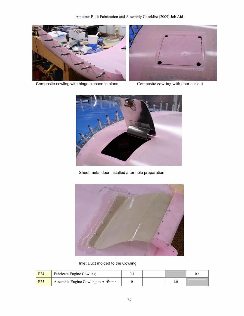
Amateur-Built Fabrication and Assembly Checklist (2009) Job Aid
Composite cowling with hinge clecoed in place Composite cowling with door cut-out
Sheet metal door installed after hole preparation
Inlet Duct molded to the Cowling
P24 Fabricate Engine Cowling 0.4 0.6
P25 Assemble Engine Cowling to Airframe 0 1.0
75

Amateur-Built Fabrication and Assembly Checklist (2009) Job Aid
The cowling on most amateur built aircraft is made from either aluminum sheet metal or composite material. In either case the material is less important than the work required to complete the task. In some cases the cowling comes preformed but the builder must do finishing work and as shown above, install the hinges and nutplates (shown above) which is considered fabrication) add internal ducting and cut out access doors/panels. In the composite cowling shown above, even though they came from the factory properly sized and shaped, significant work is required by the builder to complete the part and make it ready for assembly to the aircraft. In this case the amount of work warrants at least a 0.6 for the builder.
P26 Fabricate Engine Fuel System Components
N/A -
P27 Assemble Engine Fuel System Components to Next Level Structure
Tasks P26 and P27 refer to valves and pumps. Serious consideration is being given to recognizing the fabrication of these components as a non-checklist items but still keeping the assembly task so the builder can receive credit for installing them in the aircraft. NKET has routinly assigned an “N/A” in the P26 task so the manufacturer is not penalized for providing this in a kit.
Landing Gear Section
Spring and Steel Landing Gear Aluminum Spring Landing Gear
76

Amateur-Built Fabrication and Assembly Checklist (2009) Job Aid
Composite (Carbon Fiber) Spring Landing Gear
Aluminum Landing Gear Struts from the factory
Steel Tube and bungy system used on Cub-like aircraft kits
77
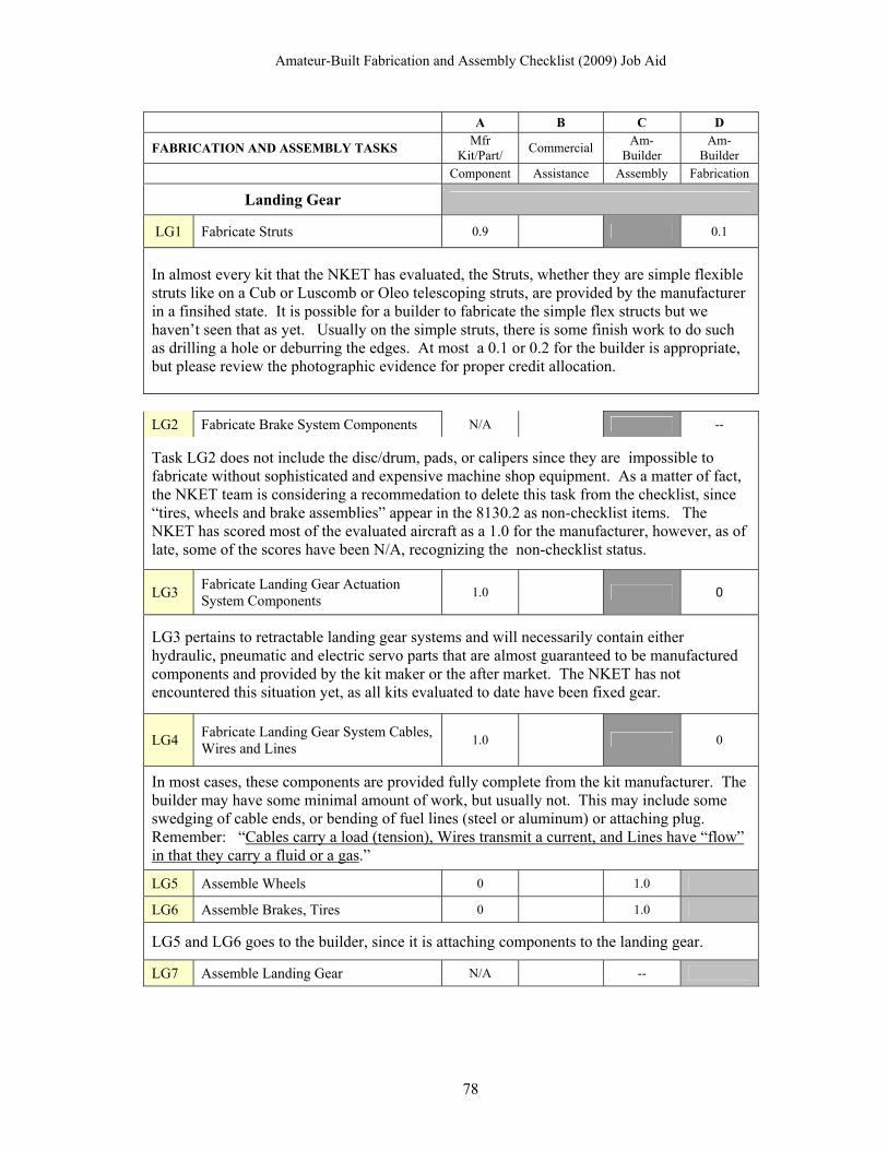
Amateur-Built Fabrication and Assembly Checklist (2009) Job Aid
A B C D
FABRICATION AND ASSEMBLY TASKS Mfr
Kit/Part/ Commercial
Am-Builder
Am-Builder
Component Assistance Assembly Fabrication
Landing Gear
LG1 Fabricate Struts 0.9 0.1
In almost every kit that the NKET has evaluated, the Struts, whether they are simple flexible struts like on a Cub or Luscomb or Oleo telescoping struts, are provided by the manufacturer in a finsihed state. It is possible for a builder to fabricate the simple flex structs but we haven’t seen that as yet. Usually on the simple struts, there is some finish work to do such as drilling a hole or deburring the edges. At most a 0.1 or 0.2 for the builder is appropriate, but please review the photographic evidence for proper credit allocation.
LG2 Fabricate Brake System Components N/A --
Task LG2 does not include the disc/drum, pads, or calipers since they are impossible to fabricate without sophisticated and expensive machine shop equipment. As a matter of fact, the NKET team is considering a recommedation to delete this task from the checklist, since “tires, wheels and brake assemblies” appear in the 8130.2 as non-checklist items. The NKET has scored most of the evaluated aircraft as a 1.0 for the manufacturer, however, as of late, some of the scores have been N/A, recognizing the non-checklist status.
LG3 Fabricate Landing Gear Actuation System Components
1.0 0
LG3 pertains to retractable landing gear systems and will necessarily contain either hydraulic, pneumatic and electric servo parts that are almost guaranteed to be manufactured components and provided by the kit maker or the after market. The NKET has not encountered this situation yet, as all kits evaluated to date have been fixed gear.
LG4 Fabricate Landing Gear System Cables, Wires and Lines
1.0 0
In most cases, these components are provided fully complete from the kit manufacturer. The builder may have some minimal amount of work, but usually not. This may include some swedging of cable ends, or bending of fuel lines (steel or aluminum) or attaching plug. Remember: “Cables carry a load (tension), Wires transmit a current, and Lines have “flow” in that they carry a fluid or a gas.”
LG5 Assemble Wheels 0 1.0
LG6 Assemble Brakes, Tires 0 1.0
LG5 and LG6 goes to the builder, since it is attaching components to the landing gear.
LG7 Assemble Landing Gear N/A --
78

Amateur-Built Fabrication and Assembly Checklist (2009) Job Aid
LG7 is putting the landing gear together. In the case of the spring landing gear as shown in the photos above, this would be N/A since there is nothing to assemble. The component comes as a single fabricated piece and is merely fitted with the wheels and brakes. Attaching these simple spring gear to the fuselage is captured in the next task (LG8). If the landing gear is a sophisticated unit utilizing an internal spring or hydraulic/pheumatic system, most likely it is going to come prefabricated from a supplier and then the manufacturer would be awarded the full credit in column “A.” In some cases, the builder has to assemble multiple parts together such as the steel spring landing gear photograph shown above. In that case the builder would receive full credit for LG7 in column “C.”
LG8 Assemble Landing Gear System Components Next Level Structure
0 1.0
LG8 is simply attaching the landing gear to the aircraft fuselage or wings and is in almost all instances awarded to the builder.
LG9 Align Landing Gear N/A -- --
LG 9 is neither fabrication or assembly and receives no credit. The NKET has determined that this function is part of the normal requirement to ensure that all systems are operating correctly and should not be considered for awarding credit for the builder or manufacturer.
LG10 Fabricate Landing Gear Fairings/Gear Doors
0.7 0.3
LG11 Assemble Landing Gear Fairings/Gear Doors to Next Level Structure
0 1.0
LG10/11 is similar to the fuselage doors/windows in that in many instances the manufacturer will provide a frame or component that requires the builder to perform some finishiing work to complete the part. NKET has scored this as low as a 0.4 and up to a 0.8 for the manufacturer, depending on the state of completion of the part received in the kit. Score as appropriate.
LG12 Perform Landing Gear Operations Check (Normal, Emergency Systems)
N/A -- --
LG12 is neither fabrication or assembly and receives no credit. The NKET has determined that this function is part of the normal requirement to ensure that all systems are operating correctly and should not be considered for awarding credit for the builder or manufacturer.
LG13 Fabricate Landing Gear Bracket and Fittings
0.8 0.2
LG14 Assemble Landing Gear Bracket and Fittings
0 1.0
Aileron Brackets and Fittings are largely fabricated at the factory but need to be trimmed, drilled, deburred and riveted (assembled) in place. Usually a minor level work is available to the builder for fabrication and full credit for the assemble operation as shown above.
79

Amateur-Built Fabrication and Assembly Checklist (2009) Job Aid
Cockpit Section
Instrument Panel The instrument panel in the photo above is ready to install in the aircraft. Unfortunately the photo above provides no evidence as to how it reached this state of completion. This emphesizes the critical nature of having original condition photographs of components or raw stock to support credit allocation decisions.
Mfr Kit/Part/
Commercial Am-
Builder Am-Builder FABRICATION AND ASSEMBLY
TASKS Component Assistance Assembly Fabrication
C1 Fabricate Instrument Panel ? ?
The photographs below shows that the panel received from the manufacturer was cut to the basic shape and the builder had to cut out all the holes, which all counts for fabrication. The builder in this situation is probably doing at least half the work, as reflected below.
C1 Fabricate Instrument Panel 0.5 0.5
80

Amateur-Built Fabrication and Assembly Checklist (2009) Job Aid
C2 Fabricate Instrument Panel Bracket and Fittings
? ?
Be careful with this task. These brackets are frequently much more involved than just the simple 3 or 4 inch triangle and “L” shaped brackets throughout the rest of the aircraft. For this task you must take into consideration all the support brackets and mounting harware that hold and contains the avionics and insturments behind the panel. Some of these parts are quite large and require extensive fabrication work (i.e., cutting, trimming, drilling, etc.) and some kits don’t provide much of hardware with the kit. You will have to determine what was provided in the kit and what the builder did to make it usable in the aircraft.
Component Assistance Assembly Fabrication
C3 Assemble Instrument Panel with Fittings and Brackets
0 1.0
C4 Assemble Avionics to Instument Panel N/A --
Task C3 is a typical assembly task and as such the credit is awarded to the builder. Task C4 was mistakenly added to the checklist and should always be scored as an N/A. The assembly of avionics and instruments to the panel is noted in the FAA Order as a “Non-Checklist” item and a builder may use commercial assistance with out penalty. This task will be removed from the checklist at the next revision.
Seatback cushions
81

Amateur-Built Fabrication and Assembly Checklist (2009) Job Aid
Mfr Kit/Part/
Commercial Am-Builder Am-
Builder FABRICATION AND ASSEMBLY TASKS Component Assistance Assembly Fabrication
C5 Fabricate Seats 0 1.0
C6 Fabricate Seat Brackets and Fittings 0.8 0.2
C7 Assemble Seats to Cockpit 0 1.0
Notice in the two photos above that the seats appear in unfinished condition in different stages of fabrication. This is the type of evidence required to award major or complete credit for task C5 above. For C6, if the kit came with brackets and fittings, score as usual with most of the credit going to the manufacturer as shown above.
C8 Fabricate Seat Belts Fittings and Shoulder Harness Fittings
1.0 0
C9 Assemble Seat Belts and Shoulder Harness to Structure
0 1.0
Usually the seat belt fittings and shoulder harness fittings are provided in the kit, but some builders make them from raw metal stock. In thirteen aircraft kits evaluated by the NKETover 2 years, task C8 has been scored a 1/0 for the manufacturer in every instance.
C10 Fabricate Electrical Wiring, Controls and Switches
1.0 0
C11 Assemble Electrical Systems Controls and Switches to Next Level Structure.
0 1
The same reasoning and virtually same results from tasks C8 and C9 apply to tasks C10 and C11.
82

Amateur-Built Fabrication and Assembly Checklist (2009) Job Aid
83
C12 Add item: Fabricate Closeout Panels/Floor Panels
? ?
C13 Add itme: Assemble Closeout Panels/Floor Panels
? ?
These tasks were added to the checklist after the first NKET evaluation and all the subsequent evaluations as well. Make a determination based on your estimate of work from the foregoing examples and enter a score.
Conclusion This Job Aid is a presentation of the basic criteria used to evaluate (for major portion) an already completed aircraft construction project derived from an amateur-built kit. The information provided is not intended to be totally comprehensive for every type of aircraft, construction technique, or material encountered. Rather, the examples and discussion presented are meant to provide enough examples and comparisons in the process so that an ASI or DAR may be successful in applying the principles involved in completing an Amateur-Built Fabrication and Assembly Checklist (2009) when required. The writers hope that this guide proves to be useful to those aviation safety experts so tasked, across the many types of aircraft and materials/techniques encountered in the field. If you have any questions or suggestions on the content of this guide, please contact the Evaluations and Special Projects Branch, AIR-240, at (202) 385-6346.


![Amateur Operato Advanced - Australian Maritime College · Amateur Operato Advanced Syllabus and Examination. The Amateur Licence (amateur advanced station) [the Advanced Amateur Licence]](https://img.dokumen.tips/doc/110x75/5f072ed67e708231d41bb822/amateur-operato-advanced-australian-maritime-college-amateur-operato-advanced.jpg)