Embed Size (px)
Citation preview

Always read before installation.
Aisin Gas Heat Pump Air Conditioner
GHP OUTDOOR UNIT INSTALLATION INSTRUCTIONS E1 Combination Multi Type
Standard - Renewal [Model P450 - P560 - P710]
Applicable models
Specification
Outdoor unit Mod. Natural gas LPG G25 CAT AWS W-KIT
P450 AWGP450 E1 N(F)WE P(F)WE G(F)WE D A K
P560 AWGP560 E1 N(F)WE P(F)WE G(F)WE D A K Combination multi
zone type Standard specification
P710 AWGP710 E1 N(F)WE P(F)WE G(F)WE D A K
P450 AWYGP450 E1 N(F)WE P(F)WE G(F)WE D A K
P560 AWYGP560 E1 N(F)WE P(F)WE G(F)WE D A K Combination multi
zone type Renewal specification
P710 AWYGP710 E1 N(F)WE P(F)WE G(F)WE D A K
(F) Indicates the cold district model specification
A word to the person in charge of installation
This GHP OUTDOOR UNIT INSTALLATION INSTRUCTIONS provides the installation procedures and precau- tions for those with a basic knowledge of gas heat pumps. Improper installation will not realize the unit’s full perfor- mance potential and could even cause injury or damage to the unit. Accordingly, read and fully understand the contents of this manual before beginning the installation of the GHP out- door unit, and install the GHP properly according to the content of this manual. If indoor units, a remote controller or other options, sold separately, are also to be installed, read and fully understand the contents of those units’ manuals as well.
Important reminder Be sure to check the model code of the GHP outdoor unit before installation. (The model code is
written on the plate at the bottom-right position in the rear of the GHP.)
This unit must be installed by specially trained personnel.
The installation must be surely performed in accordance with the contents of this manual.
Perform test operation within 3 months since installation of the GHP on the base and anyway within one year since the delivery
After installation, always call the local AISIN Authorised Service centre to perform commissioning.
621471-20E32 EN

Safety Precautions
In this manual, the precautions to prevent injuries and damages that can occur if this unit is improperly installed are divided into and covered under the “ Warning” and “ Caution” graphics. In addition, “symbols” are used to indicate proper instructions. Follow these instructions carefully.
What “ Warning” and “ Caution” mean
Warning If the items with this symbol shown in this manual are not adhered to, serious injury or death could occur.
Caution If the items with this symbol shown in this manual are not adhered to, injury or damage to the unit could occur.
What “symbols” mean
This indicates prohibited action.
This indicates an action or requirement that must be completed.
AISIN and Tecnocasa decline any responsibility for any damage whatever caused by improper use of the unit and/or non compliance with the information contained in the present manual. Specifications, drawings and technical information within this manual are subjected to change without notice.

Ref
eren
ce
Afte
r Ins
talla
tion
Elec
tric
al
Mai
n U
nit a
nd P
ipin
g
TABLE OF CONTENTS Main Unit and Piping
1. Before Installing...........................................4
1-1. Notes for renewal specification (reusing existing piping).................................. 4
1-2. Combinations and capacities of the outdoor units and indoor units .................. 5
1-3. Parts provided ................................................ 6 1-4. Locally procured parts .................................... 6
2. Transporting Outdoor Unit ...........................7 2-1. Checking the transporting route ..................... 7 2-2. Methods for transporting the outdoor unit....... 7 2-3. Dimensions related to transporting
the outdoor unit............................................... 7
3. Installation ...................................................8 3-1. Selecting the location for installation .............. 8 3-2. Space required for installation ...................... 10 3-3. Foundation and anchor bolt specifications ....11
4. Refrigerant Piping......................................13 4-1. Outline diagram of refrigerant piping ............ 13
4-2. Check existing piping specifications .............. 14 4-3. Refrigerant piping installation specifications ... 14 4-4. Refrigerant piping - Selecting branch pipes
and permissible lengths................................ 18 4-5. Precautions during the installation
of refrigerant piping ...................................... 27 4-6. Notes for branch piping ................................ 31 4-7. Stop valve connections and
opening / closing .......................................... 32 4-8. Refrigerant vapor leakage test and
vacuuming .................................................... 33 4-9. Charging the refrigerant ............................... 35 4-10.Refrigerant piping insulation and
heat retention ............................................... 36 4-11.How to secure refrigerant piping .................. 36
5. Fuel Gas Piping Installation ...................... 38
6. Drain Piping Installation ............................ 39
7. How to Extend Exhaust Pipe .................... 42 Electrical
8. Summary of Electric Wire Installation........44
8-1. Opening for power supply wires / signal wires................................................... 44
8-2. Wiring example............................................. 45
9. Electric Wire Specifications and Precautions ..............................................47 9-1. Power supply wire ........................................ 47
9-2. Signal wire between indoor-outdoor units, outdoor-outdoor units, and between combined outdoor units ................................ 48
9-3. Remote control wire ..................................... 49
10. Power Supply Wiring Procedure ............... 50 10-1.Wiring instruction.......................................... 50 10-2.Wiring length ................................................ 52 10-3.Branch wiring ............................................... 53
After Installation
11. Various Function Settings..........................54 11-1.Address setting method of the indoor and
outdoor units ................................................. 54 11-2.EEP dip switch setting.................................. 54 11-3.Gas type setting ........................................... 57 11-4.Field settings with the remote controller....... 58 11-5.List of setting contents and mode numbers....59
12. Remote Control......................................... 61
12-1.Remote control with 2 remote controllers..... 61 12-2.Group control .............................................. 61
13. Test Operation........................................... 62 13-1.Before starting test operation ....................... 62 13-2.Process of the outdoor unit when turning
on the power................................................. 62 13-3.When installing additional indoor / outdoor
units or replacing the indoor / outdoor unit PCB .............................................................. 66
Reference
14. Installation Check List ...............................68
(Reference) Troubleshooting ............................69
1. Error code display ........................................ 69 2. Cancelling the error codes ........................... 71 (Reference) GHP specifications.................72
3

1. Before Installing 1-1. Notes for renewal specification (reusing existing piping)
When performing renewal installation (reusing existing piping), read this manual and “Gas heat pump air conditioner renewal manual” carefully, and install the unit properly according to the contents of the manuals. Improper installation will not realize the unit’s full performance potential and could even cause damage to the unit.
Items to be checked for renewal installation
1) Installing outdoor units Be sure to use M 12 anchor bolts if the anchor bolts are smaller than M12. If the location of the anchor bolts is differ-
ent from the bolt location of this unit, location change is necessary. (Refer to “3-3. Foundation and anchor bolt spec- ifications” on page 11.)
When performing renewal installation from EHP, check the strength and size of the foundation. Foundation change is necessary if the strength is insufficient.
When performing renewal installation from EHP, install an antivibration mount if a vibration problem is likely to occur. (Refer to “3-3. 3) Antivibration mount” on page 12.)
2) Installing indoor units
Because the location of the suspension bolts for the indoor units are changed, install the indoor units according to the new indoor unit specification.
3) Fuel gas piping
Replace the reinforced gas hose of the existing outdoor unit with the new hose. (Gas hose change is required if the gas piping connecting location or connection size is different between the existing outdoor unit and new outdoor unit.) (Refer to “5. Fuel gas piping installation” on page 37.)
When performing renewal installation from EHP, new installation of the fuel gas piping is required.
4) Refrigerant piping and refrigerant oil
Design pressure of the pipes and branch pipes must be 3.3 MPa or higher. Check that the pipes have no corrosion.
The height difference between the indoor and outdoor units, and between indoor units must be within specification range of the new outdoor unit (AISIN GHP). (Refer to “4. Refrigerant Piping” on page 13.)
Once the existing outdoor units or indoor units are removed, block the refrigerant pipes with a tape as soon as
possible to prevent water or dust from entering the piping.
If the pipe size is different between existing piping and renewal unit piping (including indoor unit piping), connect the pipes by changing the size with the reducer or other means.
Look into the trouble history of the existing units. Check if there were any troubles such as compressor failure or
refrigerant shortage possibly due to piping failure. If there are such trouble histories, check if the troubled part was repaired. If the troubled part was not repaired, repair the part.
Clean up the piping if there is a history of compressor failure.
If the thermal insulation or lagging of the existing piping is deteriorated, repair the insulation or attach the new
insulation.
Pay attention to the refrigerant oil. Piping cleaning is necessary depending on the refrigerant oil type. (Refer to “Gas heat pump air conditioner renewal manual”.)
The piping without insulation on the liquid pipe can not be used.
The flare nuts connected to the existing indoor units must be replaced with the flare nuts attached to the new indoor
units.
4

trical
Elec
nstallation I er t f A
e
en
c r e Ref
Mai
n U
nit a
nd P
ipin
g
1. Before Installing
The foreign objects left in the piping can cause expansion valve malfunction or strainer clogging. If the existing out- door units are operable, operate cooling for 10-15 minutes, and then perform pump down operation before removal. After that, remove the existing outdoor units.
5) Drain piping
If the drain piping of the existing indoor units has clogging or insulator deterioration, replace the drain piping with the new one. (Refer to “6. Drain Piping Installation” on page 38.) (If the drain pipe connecting location or size is different between the existing and new indoor units, drain piping change is required.)
If the drain piping of the existing outdoor units has clogging or material (PVC: polyvinyl chloride) deterioration,
replace the drain piping with the new one. (If the drain pipe connecting location or size is different between the existing and new outdoor units, drain piping change is required.)
6) Electric wiring
Check the specification of the power supply wiring (signal wiring between indoor and outdoor units, and remote con- trol wiring) according to “9. Electric Wire Precautions and Specifications” on page 45 of this manual. If the wiring does not meet the standard or is damaged in appearance, replace the wiring with the new one.
Refer to “Gas heat pump air conditioner renewal manual” as for how to reuse the power supply wiring, signal wiring
between indoor and outdoor units, and remote control wiring. 1-2. Combinations and capacities of the outdoor units and indoor units
Important reminder Install the indoor units that correspond to indoor air conditioning load.
Otherwise, the units frequently repeat start and stop. That could result in breakdown of the units.
The number and total capacity of the connected indoor units must be within the range shown below. Connecting indoor units out of this range could result in breakdown.
[Combined installation]
Outdoor unit Number of connectable indoor units
Total capacity of connectable indoor units (kW)
P450 + P450 Up to 63(53) 45.0 to 144.0 (117.0)
P450 + P560 Up to 63(59) 50.5 to 161.6 (131.3)
P450 + P710 Up to 63(63) 58.0 to 185.6 (150.8)
P560 + P560 Up to 63(63) 56.0 to 179.2 (145.6)
P560 + P710 Up to 63(63) 63.5 to 203.2 (165.1)
P710 + P710 Up to 63(63) 71.0 to 227.2 (184.6)
[Stand-alone installation]
Outdoor unit Number of connectable indoor units
Total capacity of connectable indoor units (kW)
P450 Up to 40 (26) 22.4 to 90.0 (58.5)
P560 Up to 50 (33) 28.0 to 112.0 (72.8)
P710 Up to 63 (41) 35.5 to 142.0 (92.3)
( ) shows the maximum value for cold district specification.
In a combination in which the total capacity of the connected indoor units exceeds the capacity of the outdoor unit, the performance of each indoor unit will be lower than its rated capacity when all indoor units are operated simultaneously. Always strive to keep the total capacity of the indoor units within the outdoor unit capacity.
Permissible piping length is restricted up to 100 m (actual length), and total piping length is restricted up to 350 m when the total capacity of the connected outdoor unit exceeds 130 % of rated capacity.
Connectable indoor units are P22 to P280.
5

1-3. Parts provided
The following parts are provided with this outdoor unit. Check the contents.
Name This manual (INSTALLATION INSTRUCTIONS)
Shape
INSTALLATION
INSTRUCTIONS
Quantity 1
Name
Reducer (vapor line) Reducer (liquid line)
Shape
Quantity 1 type, 2 pieces
(Inner diameter: 31.8/ Outer diameter: 28.6) 1 type, 1 piece
(Inner diameter: 15.0/ Outer diameter: 12.7)
Location provided Inside of refrigerant compartment
Notes Select the proper reducer according to the refrigerant pipe diameter.
Refer to 4-2. Check existing piping specifications” on page 14.
1-4. Locally procured parts
The following items are required for installing this GHP.
Parts required
Part Application
Anchor bolt For installing outdoor unit (M12 × 4 pcs) Washer, nut For installing outdoor unit (M12 × 4 pcs) Suspension bolt (M10), nut For installing indoor units (4 pcs per indoor unit)
Copper pipe (C1220T) For refrigerant piping (Refer to “4-4. Refrigerant piping - Selecting branch piping
and permissible lengths” on page 18) Hard plastic (PVC: polyvinyl chloride) pipe (VP)
For outdoor unit drain (VP20, VP30, VP50)
Steel pipe (SGP) For fuel gas piping (3/4 B) Reinforced gas hose For fuel gas piping Insulating material For refrigerant and drain pipe insulation
Power supply wire For electric power supply for indoor and outdoor units
(Refer to “9-1. Power supply wire“ on page 45)
Signal wire between indoor and out- door units
For communication between indoor and outdoor units (Refer to “9-2. Signal wire between indoor-outdoor units, outdoor-outdoor units, and between combined outdoor units” on page 46)
Remote control wire For connecting indoor unit and remote controller
(Refer to “9-3. Remote control wire” on page 47) Ground wire For grounding the outdoor unit Refrigerant For additional charging (R410A) Refrigerant oil For applying to the flares (NL10) Crimp pipe For header branch pipes
Reducer (for stand-alone installation)
Get appropriate reducers locally if the refrigerant piping equivalent length exceeds 100 m, because stand-alone installation requires pipes with diam- eters larger by one rank for the main liquid and vapor piping in such a case.
(Note) Specifications of above listed parts must comply with the relevant local and national regulations and techni-
cal standards.
6
trical
Elec
nstallation I er t f A
e
en
c r e Ref
Mai
n U
nit a
nd P
ipin
g
2. Transporting Outdoor Unit 2-1. Check the transporting route
2. Transporting Outdoor Unit
Make sure that the route to the installation site and any openings are large enough for the outdoor unit to be transported through.
Make sure that the route to the installation site has the strength to withstand the weight of the outdoor unit. 2-2. Methods for transporting the outdoor unit
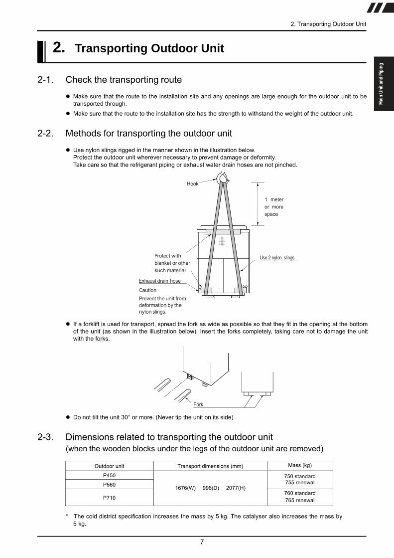
Use nylon slings rigged in the manner shown in the illustration below. Protect the outdoor unit wherever necessary to prevent damage or deformity. Take care so that the refrigerant piping or exhaust water drain hoses are not pinched.
Hook
1 meter or more space
Protect with blanket or other such material
Exhaust drain hose
Caution Prevent the unit from deformation by the nylon slings.
Use 2 nylon slings
If a forklift is used for transport, spread the fork as wide as possible so that they fit in the opening at the bottom of the unit (as shown in the illustration below). Insert the forks completely, taking care not to damage the unit with the forks.
Fork
Do not tilt the unit 30° or more. (Never tip the unit on its side) 2-3. Dimensions related to transporting the outdoor unit
(when the wooden blocks under the legs of the outdoor unit are removed)
Outdoor unit Transport dimensions (mm) Mass (kg)
P450
P560 750 standard 755 renewal
P710
1676(W) � 996(D) � 2077(H) 760 standard 765 renewal
* The cold district specification increases the mass by 5 kg. The catalyser also increases the mass by
5 kg.
7

3. Installation 3-1. Selecting the location for installation
Warning
Never install the outdoor unit at a indoor location.
Never install the outdoor unit at a location where the exhaust gas could flow into the room. If the outdoor unit is installed near the intake/exhaust port to the room, window or ventilation port, the exhaust gas could flow into the room and cause gas poisoning or an accident due to lack of oxygen.
Never install the outdoor unit in an area where flammable gas can be produced, flow into, accumulate or leak, or where volatile flammable materials can be treated. Installation at such locations could result in a fire or an explosion.
Always install the outdoor unit at an outdoor area open to the atmosphere. If the exhaust gas accumulates, it could cause gas poisoning or an accident due to lack of oxygen. Install the outdoor unit where adequate ventilation is provided.
Make sure that the area where the outdoor unit is going to be installed is strong enough to withstand the unit’s mass. If the location is not strong enough, the outdoor unit could fall over and cause injury or accident.
Always discharge the exhaust gas to the atmosphere at a location where the gas will not cause adverse affects on the surrounding area. If the exhaust gas is exhausted into the catch basin or ditch, it could be drawn into the room and cause gas poisoning or accident due to lack of oxygen.
Caution
Never install the outdoor unit at a location where its exhaust gas or air from its blower fan will come in contact with plants or animals. The exhaust gas or discharged air could cause harm to these plants or animals.
When the outdoor unit is installed on the roof or at a high location, install a permanent ladder or railings along the path to the unit, and install a fence or railings around the unit for the worker. If these devices are not installed, the worker could fall.
* If there is no choice of installation location other than where the exhaust gas could flow into the room or could
cause harm to the surroundings, extend the exhaust pipe. refer to “7. How to extend exhaust pipe” on page 41 for details.
8

trical
Elec
nstallation I er t f A
e
en
c r e Ref
Mai
n U
nit a
nd P
ipin
g
3. Installation
Important reminder Always install the outdoor unit at a location where its operating noise and vibration will not cause
problems for those below or surrounding the unit. (This is especially important when installing in res- idential areas.)
Install the outdoor unit where the discharged air from the fan does not blow on nearby homes.
Install the outdoor unit at a level location where rainwater does not penetrate and water does not accumulate.
Install the outdoor unit at a location where it will not be exposed to strong winds.
The noise from the outdoor unit may cause adverse effect on other electrical equipment. Always install the unit at a location distant enough from the electrical equipments such as televisions, radios, computers, telephones and their antennas, electrical wires, and signal wires.
Install the outdoor unit at a location where heat from other equipment does not cause adverse effect on the unit.
If the outdoor unit is installed in a heavy snowfall area, install the unit where accumulated snow does not fall on the unit, and install the optional snow hood as well. Also make sure that the foun- dation for the unit is high enough so as not to be affected by accumulated snow.
Allocate the route for loading/unloading the equipment, materials and parts for maintenance at the installation site (minimum route width: 1200 mm, maximum mass of equipment, materials and parts: 250 kg).
9

3-2. Space required for installation
1) Provide sufficient distance from flammable materials
Warning
Install the outdoor unit in the proper distance from flammable items as required by the rel- evant local and national regulations, and technical standards. (See the reference below.) If the distance does not meet the requirements, it could result in a fire.
Reference: Fire-prevention certified gas-operated equipment (Japanese regulation)
150 or more 10 or more
(Top view)
10 or more
10 or more
600 or more
(Front view)
The front of the outdoor unit is the side where the following name plate is attached.
Distance from flammable materials (mm)
2) Installation space
Caution
The following drawings show the minimum installation space for providing room for intake air and inspection and maintenance operations. Insufficient space could result in injury to the maintenance personnel or damage to the equip- ment.
Provide ample space for inspection and maintenance taking into account the refrigerant and fuel gas piping.
Front view Top view
When the snow hood is installed provide at least 880 mm above
the unit. In any other case provide at least 2 m above the unit
Important reminder
When 4 or more of outdoor units are installed in the same location, nearby walls or other objects could obstruct air flow and cause short circuit. To prevent a decline in performance and trouble due to short circuit of airflow, larger installation space is necessary. Contact an authorized dealer for details.
10

trical
Elec
nstallation I er t f A
e
en
c r e Ref
200
200
35
35
B
(Anc
hor b
olt
spac
ing)
(b o
r mor
e)
(Fou
ndat
ion
conc
rete
)
Mai
n U
nit a
nd P
ipin
g
3. Installation 3-3. Foundation and anchor bolt specifications
1) Foundation shape
Warning
The foundation must provide a firm and level surface for installing the outdoor unit so that the outdoor unit does not tip over in the event of strong winds (typhoons, etc.) or earthquake. If the foundation strength is insufficient, the outdoor unit could tip over and cause fuel gas leakage or injury.
The foundation must have sufficient strength in accordance with the drawings below. In order to protect the out- door unit from rain, dust and damage, the height of the foundation must be 200 mm from the ground. The foun- dation must have grooves around itself that directs drain water to the drainage port.
The foundation must support the mass of the outdoor unit evenly and must be flat and smooth so that water will not accumulate on the upper surface.
Never use a foundation that consists of more than one piece of block. Such a foundation will not provide neces- sary strength.
Condensation water may drip from the bottom of the outdoor unit. Install a drain pan if the condensation water could cause problems.
<Above-ground installation> <Foundation dimensions>
Chamfred corners on the concrete
Drainage grooves
a or more (Foundation concrete)
A (Anchor bolt
spacing)
Anchor bolts
<Roof-top installation> Roughen the floor surface before pouring concrete. Insert anti vibrant rubber
Anchor bolts
Length: mm
Foundation dimensions (mm) Anchor bolt spacing (mm) Installation location/ Designed earthquake resistance a b A B
Ground/ Horizontal 0.4 G, Vertical 0.2 G
1.750
1.100
841
956
Roof-top/ Horizontal 1.0 G, Vertical 0.5 G
1.850
1.700
841*
956*
* Foresee the installation of an antivibrant mount.
Important reminder If the foundation is smaller than the specified dimensions or if the designed earthquake resis-
tance value needs to be higher than that shown in the table above, appropriate design change such as connecting the foundation to the building (floor slab) with steel rods is necessary. Such design changes should be done in accordance with the appropriate building equipment seismic tolerance design and installation policy.
11

2) Anchor bolts
Warning
Use anchor bolts that satisfy the specifications shown in the table below. Make sure the legs of the outdoor unit are firmly secured with washers and bolts. If the strength is insufficient, the unit could tip over and cause fuel gas leakage or injury.
Required anchor bolt pull out resistance strength
Size M12 Short-term permissi-
ble pull-out load 6.7 kN or more
Type • Male mechanical anchor
• Resin anchor • Embedded anchor
Never use a female mechanical anchor because its pull out resistance strength is insufficient.
3) Antivibrant mount
Anchor bolt (Procured locally) Nut/Washers (Procured locally)
Foundation
Important reminder When using an antivibrant mount to install the unit, check with the relevant local and national
regulations and technical standards, and make sure that the installation complies with the build- ing regulations, and required installation policy.
Use an antivibrant mount when operating noise or vibration could cause problems in lower floors or nearby rooms as a result of installing the outdoor unit on a roof or balcony. (For specific information about installing, refer to the manual provided with the antivibrant mount.)
Provide sufficient grooves in the top of the foundation for draining water so that the draining water will not accumulate inside the lower frame.
The foundation must be one piece. Make the foundation’s upper surface level, flat and smooth so that the lower frame of the antivibrant mount will make even contact.
The anti vibrant mount can be replaced by using an anti vibrant carpet between the foundation and the surface of the roof.
12

Mai
n Un
it an
d Pi
ping
Elec
tric
alA
fter
Inst
alla
tion
Refe
renc
e
13
4. Refrigerant Piping
4. Refrigerant Piping
4-1. Outline diagram of refrigerant piping
[Combined installation]
[Stand-alone installation]

4-2. Check existing piping specifications
Be sure to check piping specifications when reusing existing piping. Replace the piping if the existing piping does not meet the specifications shown in the table below. (Design pressure must be 3.3 MPa or higher.)
Pipe diameter (mm) C1220T-O materiel or OL material
Required minimum thickness (mm) C1220T-1/2H materiel or H material Required minimum thickness (mm)
ø6.4 0.4 - ø9.5 0.5 - ø12.7 0.7 - ø15.9 0.9 0.5 ø19.1 1.0 0.6 ø22.2 1.1 0.6 ø25.4 - 0.7 ø28.6 - 0.8 ø31.8 - 0.9 ø38.1 - 1.1 ø41.3 - 1.1
Check the appearance (such as corrosion or deformation) of the pipes when reusing existing piping. If there is any abnormality, replace the piping with new one.
Use branch pipes with design pressure of 3.3 MPa or higher. If you can not confirm the design pressure, select the branch pipes according to “4-4. Refrigerant piping - Selecting branch pipes and permissible lengths” on page 18.
If the pipe size is different between existing piping and outdoor and indoor unit piping, connect the pipes using the reducers (procured locally).
4-3. Refrigerant piping installation specifications
Follow the restriction shown in the table below when installing new refrigerant piping. [Combined installation]
Item Refrigerant piping diameter
*1 (mm) Permissible height
difference (m) Outdoor Unit (Combination Multi)
Vapor line
Liquid line
Permissible piping length (m)
Equivalent length/ Actual length Outdoor unit is
higher Outdoor unit
is lower
Refrigerant oil
P450 ø28.6 ø15.9 P560 ø28.6 ø15.9 P710 ø31.8 ø15.9
190 /165 *2
50 40 NL10
*1 Refrigerant piping diameter: From the outdoor unit to the Combination Multi connection kit. *2 When total capacity of connected indoor unit exceeds 130 % of rated capacity, restrict the permissible piping length
(actual length) to 100 m or less. [Stand-alone installation]
Item Refrigerant main piping diameter
(mm) Permissible height
difference (m) Outdoor Unit
Vapor line
Liquid line
Permissible piping length (m)
Equivalent length/ Actual length Outdoor unit is
higher Outdoor unit
is lower
Refrigerant oil
P450 ø28.6
*1(ø31.8) ø15.9
*1(ø19.1)
P560 ø28.6 *1(ø31.8)
ø15.9 *1(ø19.1)
P710 ø31.8
*1(ø38.1) ø15.9
*1(ø19.1)
190 /165 *2
50 40 NL10
*1 If the piping length exceeds 100 m, install pipes larger by one rank specified in ( ).
*2 When total capacity of connected indoor unit exceeds 130 % of rated capacity, restrict the permissible piping length (actual length) to 100 m or less.
14

Mai
n Un
it an
d Pi
ping
Elec
tric
alA
fter
Inst
alla
tion
Refe
renc
e
15
4. Refrigerant Piping
Reducer selection for combined installation
[Note: ○ means this part is used for the above-mentioned outdoor unit.]
Item Mark Name Specification Remark 45kW 56kW 71kW
Vapor refrigerant
Reducer O.D.28.6 - I.D.31.8 Provided with the outdoor unit - - ○
Reducer I.D.31.8 - O.D.28.6 Provided with the outdoor unit - - ○
Copper pipeφ28.6
Locally procured○ ○ -
φ31.8 - - ○
Liquid refrigerant
Reducer I.D.15.9 - O.D.12.7 Provided with the outdoor unit ○ ○ ○
Copper pipe φ15.9 Locally procured ○ ○ ○
Connection kit - Option ○ ○ ○
A
B
C

16
Precautions for combined installation
Arrange the refrigerant piping for both liquid and vapor between the outdoor units so that the piping is level orhas upward gradient to prevent the refrigerant oil from accumulating in the piping.
Connect the refrigerant piping between the outdoor units to the stop valve as shown in the following figure A orB. Otherwise, the refrigerant oil can accumulate in the piping.
Be sure to install the Combination Multi connection kit “horizontally” for both vapor and liquid.
Horizontal Vertical
FloorsurfaceCorrect Wrong Wrong
Floorsurface
Floorsurface
Floor surfaceWrong Wrong
Floor surface

Mai
n Un
it an
d Pi
ping
Elec
tric
alA
fter
Inst
alla
tion
Refe
renc
e
17
4. Refrigerant Piping
Make strait portion of 660 mm or more before branching of the Combination Multi connection kit.
When the piping length from the Combination Multi connection kit to the outdoor unit is 2 m or more, make a ris-ing of 200 mm or more on vapor piping only at a location 2 m or less from the Combination Multi connection kit.
4-4. Refrigerant piping - Selecting branch pipes and permissible lengths
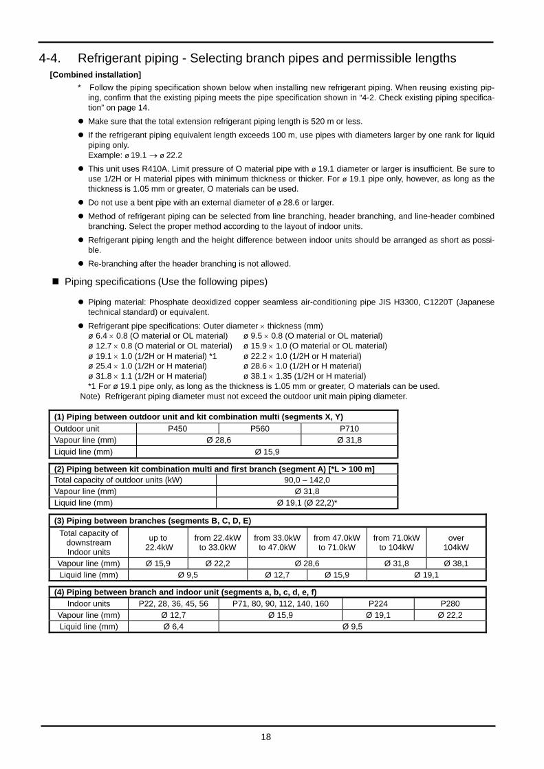
[Combined installation] * Follow the piping specification shown below when installing new refrigerant piping. When reusing existing pip-
ing, confirm that the existing piping meets the pipe specification shown in “4-2. Check existing piping specifica- tion” on page 14.
Make sure that the total extension refrigerant piping length is 520 m or less.
If the refrigerant piping equivalent length exceeds 100 m, use pipes with diameters larger by one rank for liquid piping only. Example: ø 19.1 → ø 22.2
This unit uses R410A. Limit pressure of O material pipe with ø 19.1 diameter or larger is insufficient. Be sure to use 1/2H or H material pipes with minimum thickness or thicker. For ø 19.1 pipe only, however, as long as the thickness is 1.05 mm or greater, O materials can be used.
Do not use a bent pipe with an external diameter of ø 28.6 or larger.
Method of refrigerant piping can be selected from line branching, header branching, and line-header combined branching. Select the proper method according to the layout of indoor units.
Refrigerant piping length and the height difference between indoor units should be arranged as short as possi- ble.
Re-branching after the header branching is not allowed.
Piping specifications (Use the following pipes)
Piping material: Phosphate deoxidized copper seamless air-conditioning pipe JIS H3300, C1220T (Japanese technical standard) or equivalent.
Refrigerant pipe specifications: Outer diameter × thickness (mm) ø 6.4 × 0.8 (O material or OL material) ø 9.5 × 0.8 (O material or OL material) ø 12.7 × 0.8 (O material or OL material) ø 15.9 × 1.0 (O material or OL material) ø 19.1 × 1.0 (1/2H or H material) *1 ø 22.2 × 1.0 (1/2H or H material) ø 25.4 × 1.0 (1/2H or H material) ø 28.6 × 1.0 (1/2H or H material) ø 31.8 × 1.1 (1/2H or H material) ø 38.1 × 1.35 (1/2H or H material) *1 For ø 19.1 pipe only, as long as the thickness is 1.05 mm or greater, O materials can be used.
Note) Refrigerant piping diameter must not exceed the outdoor unit main piping diameter.
(1) Piping between outdoor unit and kit combination multi (segments X, Y)
Outdoor unit P450 P560 P710 Vapour line (mm) Ø 28,6 Ø 31,8 Liquid line (mm) Ø 15,9
(2) Piping between kit combination multi and first branch (segment A) [*L > 100 m] Total capacity of outdoor units (kW) 90,0 – 142,0 Vapour line (mm) Ø 31,8 Liquid line (mm) Ø 19,1 (Ø 22,2)*
(3) Piping between branches (segments B, C, D, E)
Total capacity of downstream Indoor units
up to 22.4kW
from 22.4kW to 33.0kW
from 33.0kW to 47.0kW
from 47.0kW to 71.0kW
from 71.0kW to 104kW
over 104kW
Vapour line (mm) Ø 15,9 Ø 22,2 Ø 28,6 Ø 31,8 Ø 38,1 Liquid line (mm) Ø 9,5 Ø 12,7 Ø 15,9 Ø 19,1
(4) Piping between branch and indoor unit (segments a, b, c, d, e, f)
Indoor units P22, 28, 36, 45, 56 P71, 80, 90, 112, 140, 160 P224 P280 Vapour line (mm) Ø 12,7 Ø 15,9 Ø 19,1 Ø 22,2 Liquid line (mm) Ø 6,4 Ø 9,5
18
Mai
n Un
it an
d Pi
ping
Elec
tric
alA
fter
Inst
alla
tion
Refe
renc
e
19
4. Refrigerant Piping
Selecting branch piping and permissible piping length
Line branching
* When total capacity of connected indoor unit exceeds 130 % of rated capacity, restrict the permissible pipinglength (actual length) to 100 m.
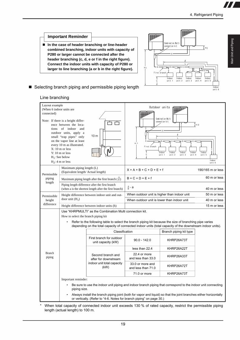
Important Reminder
In the case of header branching or line-header combined branching, indoor units with capacity of P280 or larger cannot be connected after the header branching (c, d, e or f in the right figure). Connect the indoor units with capacity of P280 or larger to line branching (a or b in the right figure).
Layout example(When 6 indoor units areconnected)
Note: If there is a height differ-ence between the loca-tions of indoor andoutdoor units, apply asmall “trap pipes” onlyon the vapor line at leastevery 10 m as illustrated.X: 10 m or lessY: 10 m or lessH1: See below
H2: 4 m or less
Permissible piping length
Maximum piping length (L) (Equivalent length/ Actual length)
X + A + B + C + D + E + f 190/165 m or less
Maximum piping length after the first branch ( ) B + C + D + E + f 60 m or less
Piping length difference after the first branch(when a is the shortest length after the first branch) - a 40 m or less
Permissible height
difference
Height difference between indoor unit and out-door unit (H1)
When outdoor unit is higher than indoor unit 50 m or less
When outdoor unit is lower than indoor unit 40 m or less
Height difference between indoor units (h) 15 m or less
Branchpiping
Use “KHRPMULTI” as the Combination Multi connection kit.How to select the branch piping kit
• Refer to the following table to select the branch piping kit because the size of branching pipe varies depending on the total capacity of connected indoor units (total capacity of the downstream indoor units).
Classification Branch piping kit type
First branch for outdoor unit capacity (kW) 90.0 - 142.0 KHRP26A73T
Second branch and after for downstream
indoor unit total capacity (kW)
less than 22.4 KHRP26A22T
22.4 or moreand less than 33.0 KHRP26A33T
33.0 or more andand less than 71.0 KHRP26A72T
71.0 or more KHRP26A73T
Important reminder:
• Be sure to use the indoor unit piping and indoor branch piping that correspond to the indoor unit connecting piping size.
• Always install the branch piping joint (both for vapor and liquid) so that the joint branches either horizontally or vertically. (Refer to “4-6. Notes for branch piping” on page 30.)
10 m

20
Header branching
* When total capacity of connected indoor unit exceeds 130 % of rated capacity, restrict the permissible pipinglength (actual length) to 100 m.
Layout example(When 6 indoor units areconnected)
Note: If there is a height differ-ence between the loca-tions of indoor andoutdoor units, apply asmall “trap pipes” only onthe vapor line at leastevery 10 m as illustrated.X: 10 m or lessY: 10 m or lessH1: See below
H2: 4 m or less
Permissible piping length
Maximum piping length (L) (Equivalent length/Actual length)
X + A + f 190/165 m or less
Maximum piping length after the first branch ( ) f 60 m or less
Piping length difference after the first branch(when a is the shortest length after the first branch) - a 40 m or less
Permissible height
difference
Height difference between indoor unit and out-door unit (H)
When outdoor unit is higher than indoor unit 50 m or less
When outdoor unit is lower than indoor unit 40 m or less
Height difference between indoor units (h) 15 m or less
Branchpiping
Use “KHRPMULTI” as the Combination Multi connection kit.How to select the header piping kit
• Connect crimp piping (locally procured) to the branching points (on the indoor unit connection side) in accordance with the number of connected indoor units.
• Refer to the header branching kit (sold separately) for the crimp piping size.
Total capacity of down-stream indoor units (kW) Header kit type Number of branches
less than 22.4 KHRP26M22H Up to 4 branches
22.4 or moreand less than 33.0 KHRP26M33H
Up to 8 branches33.0 or moreand less than 71.0 KHRP26M72H
71.0 or more KHRP26M73H
Important reminder:
• Be sure to use the header branching and indoor unit piping that correspond to the indoor unit connecting piping size.
• Always install the header branching joint (both vapor and liquid sides) so that the joint branches horizontally. (Refer to “4-6. Notes for branch piping” on page 30.)
• Re-branching after the header branching is not allowed. Besides, the indoor unit with capacity of P280 or larger can not be connected after the header branching.
10 m

Mai
n Un
it an
d Pi
ping
Elec
tric
alA
fter
Inst
alla
tion
Refe
renc
e
21
4. Refrigerant Piping
Line - header combined branching
* When total capacity of connected indoor unit exceeds 130 % of rated capacity, restrict the permissible pipinglength (actual length) to 100 m.
Layout example(When 6 indoor units areconnected)
Note: If there is a height differ-ence between the loca-tions of indoor andoutdoor units, apply asmall “trap pipes” only onthe vapor line at leastevery 10 m as illustrated.X: 10 m or lessY: 10 m or lessH1: See below
H2: 4 m or less
Permissible piping length
Maximum piping length (L) (Equivalent length/Actual length)
X + A + B + C + f 190/165 m or less
Maximum piping length after the first branch ( ) B + C + f 60 m or less
Piping length difference after the first branch(when a is the shortest length after the first branch) - a 40 m or less
Permissible height dif-
ference
Height difference between indoor unit and out-door unit (H)
When outdoor unit is higher than indoor unit 50 m or lessWhen outdoor unit is lower than indoor unit 40 m or less
Height difference between indoor units (h) 15 m or less
Branchpiping
Use “KHRPMULTI” as the Combination Multi connection kit.How to select the branch piping kit
• Refer to the following table to select the branch piping kit because the size of branching pipe varies depending on the total capacity of connected indoor units (total capacity of the downstream indoor units).
Classification Branch piping kit type
First branch for outdoor unit capacity (kW) 90.0 - 142.0 KHRP26A73T
Second branch and after for downstream indoor unit
total capacity (kW)
less than 22.4 KHRP26A22T22.4 or more
and less than 33.0 KHRP26A33T
33.0 or moreand less than 71.0 KHRP26A72T
71.0 or more KHRP26A73T
Important reminder:
• Be sure to use the indoor unit piping and indoor branch piping that correspond to the indoor unit connecting piping size.
• Always install the branch piping joint (both for vapor and liquid) so that the joint branches either horizontally or vertically. (Refer to “4-6. Notes for branch piping” on page 30.)
How to select the header piping kit
• Connect crimp piping (locally procured) to the branching points (on the indoor unit connection side) in accor-dance with the number of connecting indoor units.
• Refer to the header branching kit (sold separately) for the crimp piping size.
Total capacity of down-stream indoor units (kW) Header kit type Number of branches
less than 22.4 KHRP26M22H Up to 4 branches22.4 or more
and less than 33.0 KHRP26M33H
Up to 8 branches33.0 or moreand less than 71.0 KHRP26M72H
71.0 or more KHRP26M73H
Important reminder:
• Be sure to use the header branching and indoor unit piping that correspond to the indoor unit connecting piping size.
• Always install the header branching joint (both vapor and liquid sides) so that the joint branches horizontally. (Refer to “4-6. Notes for branch piping” on page 30.)
• Re-branching after the header branching is not allowed. Besides, the indoor unit with capacity of P280 or larger can not be connected after the header branching.
10 m

[Stand-alone installation] * Follow the piping specification shown below when installing new refrigerant piping. When reusing existing pip-
ing, confirm that the existing piping meets the pipe specification shown in “4-2. Check existing piping specifica- tion” on page 14.
Make sure that the total extension refrigerant piping length is 520 m or less.
If the refrigerant piping equivalent length exceeds 100 m, use pipes with diameters larger by one rank indicated in “4-3. Refrigerant piping installation specifications“ on page 14 for the main liquid and vapor piping. Example: ø 12.7 → ø 15.9
This unit uses R410A. Limit pressure of O material pipe with ø 19.1 diameter or larger is insufficient. Be sure to use 1/2H or H material pipes with minimum thickness or thicker. For ø 19.1 pipe only, however, as long as the thickness is 1.05 mm or greater, O materials can be used.
Do not use a bent pipe with an external diameter of ø 28.6 or larger.
Method of refrigerant piping can be selected from line branching, header branching, and line-header combined branching. Select the proper method according to the layout of indoor units.
Refrigerant piping length and the height difference between indoor units should be arranged as short as possi- ble.
Re-branching after the header branching is not allowed.
Piping specifications (Use the following pipes)
Piping material: Phosphate deoxidized copper seamless air-conditioning pipe compliant with local technical standard or equivalent.
Refrigerant pipe specifications: Outer diameter × thickness (mm) ø 6.4 × 0.8 (O material or OL material) ø 9.5 × 0.8 (O material or OL material) ø 12.7 × 0.8 (O material or OL material) ø 15.9 × 1.0 (O material or OL material) ø 19.1 × 1.0 (1/2H or H material) *1 ø 22.2 × 1.0 (1/2H or H material) ø 25.4 × 1.0 (1/2H or H material) ø 28.6 × 1.0 (1/2H or H material) ø 31.8 × 1.1 (1/2H or H material) ø 38.1 × 1.35 (1/2H or H material) *1 For ø 19.1 pipe only, as long as the thickness is 1.05 mm or greater, O materials can be used.
Note) Refrigerant piping diameter must not exceed the outdoor unit main piping diameter.
(1) Piping between outdoor unit and kit combination multi (segment A)
Outdoor unit P450 P560 P710 Vapour line (mm) Ø 28,6 (31,8)* Ø 31,8 (38,1)* Liquid line (mm) Ø 15,9 (19,1)*
(2) Piping between branches (segments B, C, D, E)
Total capacity of downstream Indoor units
up to 22.4kW
from 22.4kW to 33.0kW
from 33.0kW to 47.0kW
from 47.0kW to 71.0kW
from 71.0kW to 104kW
over 104kW
Vapour line (mm) Ø 15,9 Ø 22,2 Ø 28,6 Ø 31,8 Ø 38,1 Liquid line (mm) Ø 9,5 Ø 12,7 Ø 15,9 Ø 19,1
(3) Piping between branch and indoor unit (segments a, b, c, d, e, f)
Indoor units P22, 28, 36, 45, 56 P71, 80, 90, 112, 140, 160 P224 P280 Vapour line (mm) Ø 12,7 Ø 15,9 Ø 19,1 Ø 22,2 Liquid line (mm) Ø 6,4 Ø 9,5
22
Mai
n Un
it an
d Pi
ping
Elec
tric
alA
fter
Inst
alla
tion
Refe
renc
e
23
4. Refrigerant Piping
Selecting branch piping and permissible piping length
Line branching
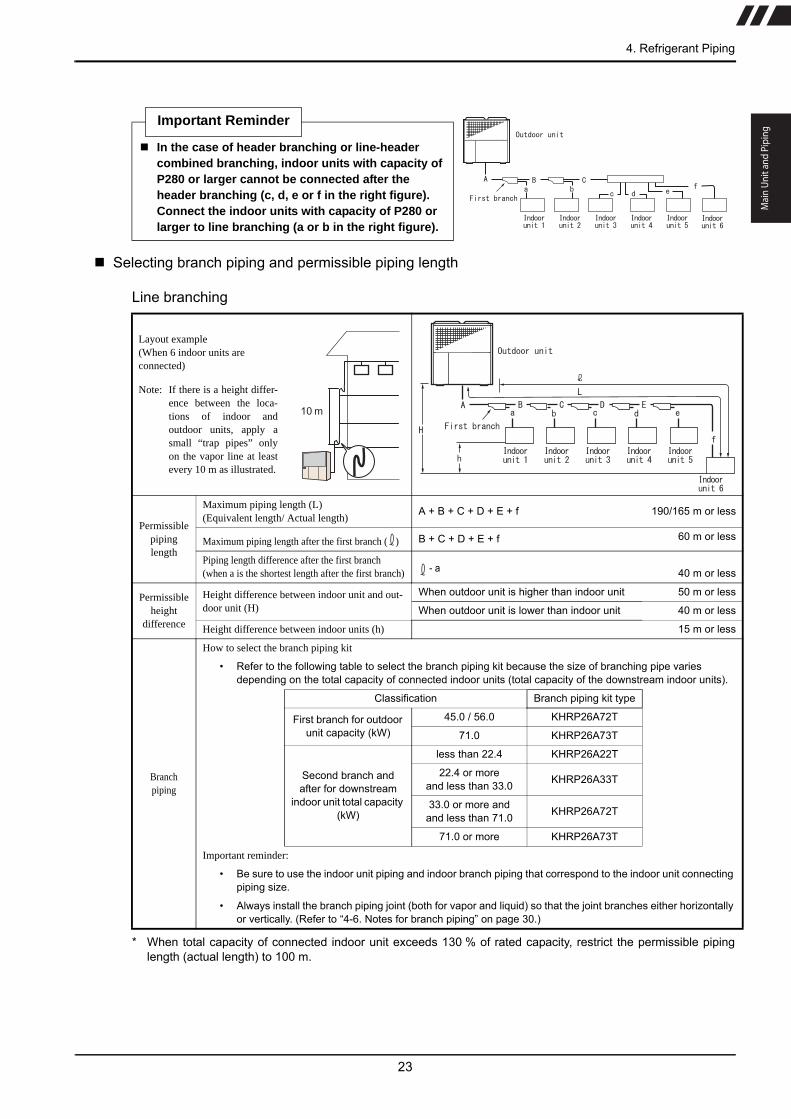
* When total capacity of connected indoor unit exceeds 130 % of rated capacity, restrict the permissible pipinglength (actual length) to 100 m.
Important Reminder
In the case of header branching or line-header combined branching, indoor units with capacity of P280 or larger cannot be connected after the header branching (c, d, e or f in the right figure). Connect the indoor units with capacity of P280 or larger to line branching (a or b in the right figure).
Layout example(When 6 indoor units areconnected)
Note: If there is a height differ-ence between the loca-tions of indoor andoutdoor units, apply asmall “trap pipes” onlyon the vapor line at leastevery 10 m as illustrated.
Permissible piping length
Maximum piping length (L) (Equivalent length/ Actual length)
A + B + C + D + E + f 190/165 m or less
Maximum piping length after the first branch ( ) B + C + D + E + f 60 m or less
Piping length difference after the first branch(when a is the shortest length after the first branch) - a 40 m or less
Permissible height
difference
Height difference between indoor unit and out-door unit (H)
When outdoor unit is higher than indoor unit 50 m or less
When outdoor unit is lower than indoor unit 40 m or less
Height difference between indoor units (h) 15 m or less
Branchpiping
How to select the branch piping kit
• Refer to the following table to select the branch piping kit because the size of branching pipe varies depending on the total capacity of connected indoor units (total capacity of the downstream indoor units).
Classification Branch piping kit type
First branch for outdoor unit capacity (kW)
45.0 / 56.0 KHRP26A72T
71.0 KHRP26A73T
Second branch and after for downstream
indoor unit total capacity (kW)
less than 22.4 KHRP26A22T
22.4 or moreand less than 33.0 KHRP26A33T
33.0 or more andand less than 71.0 KHRP26A72T
71.0 or more KHRP26A73T
Important reminder:
• Be sure to use the indoor unit piping and indoor branch piping that correspond to the indoor unit connecting piping size.
• Always install the branch piping joint (both for vapor and liquid) so that the joint branches either horizontally or vertically. (Refer to “4-6. Notes for branch piping” on page 30.)
10 m

24
Header branching
* When total capacity of connected indoor unit exceeds 130 % of rated capacity, restrict the permissible pipinglength (actual length) to 100 m.
Layout example(When 6 indoor units areconnected)
Note: If there is a height differ-ence between the loca-tions of indoor andoutdoor units, apply asmall “trap pipes” only onthe vapor line at leastevery 10 m as illustrated.
Permissible piping length
Maximum piping length (L) (Equivalent length/Actual length)
A + f 190/165 m or less
Maximum piping length after the first branch ( ) f 60 m or less
Piping length difference after the first branch(when a is the shortest length after the first branch) - a 40 m or less
Permissible height
difference
Height difference between indoor unit and out-door unit (H)
When outdoor unit is higher than indoor unit 50 m or less
When outdoor unit is lower than indoor unit 40 m or less
Height difference between indoor units (h) 15 m or less
Branchpiping
How to select the header piping kit
• Connect crimp piping (locally procured) to the branching points (on the indoor unit connection side) in accordance with the number of connected indoor units.
• Refer to the header branching kit (sold separately) for the crimp piping size.
Total capacity of down-stream indoor units (kW) Header kit type Number of branches
less than 22.4 KHRP26M22H Up to 4 branches
22.4 or moreand less than 33.0 KHRP26M33H
Up to 8 branches33.0 or moreand less than 71.0 KHRP26M72H
71.0 or more KHRP26M73H
Important reminder:
• Be sure to use the header branching and indoor unit piping that correspond to the indoor unit connecting piping size.
• Always install the header branching joint (both vapor and liquid sides) so that the joint branches horizontally. (Refer to “4-6. Notes for branch piping” on page 30.)
• Re-branching after the header branching is not allowed. Besides, the indoor unit with capacity of P280 or larger can not be connected after the header branching.
10 m
Mai
n Un
it an
d Pi
ping
Elec
tric
alA
fter
Inst
alla
tion
Refe
renc
e
25
4. Refrigerant Piping
Line - header combined branching
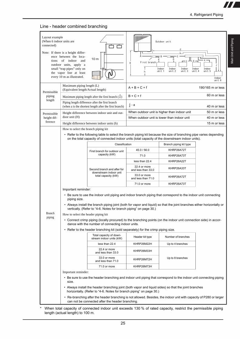
* When total capacity of connected indoor unit exceeds 130 % of rated capacity, restrict the permissible pipinglength (actual length) to 100 m.
Layout example(When 6 indoor units areconnected)
Note: If there is a height differ-ence between the loca-tions of indoor andoutdoor units, apply asmall “trap pipes” only onthe vapor line at leastevery 10 m as illustrated.
Permissible piping length
Maximum piping length (L) (Equivalent length/Actual length)
A + B + C + f 190/165 m or less
Maximum piping length after the first branch ( ) B + C + f 60 m or less
Piping length difference after the first branch(when a is the shortest length after the first branch) - a 40 m or less
Permissible height dif-
ference
Height difference between indoor unit and out-door unit (H)
When outdoor unit is higher than indoor unit 50 m or less
When outdoor unit is lower than indoor unit 40 m or less
Height difference between indoor units (h) 15 m or less
Branchpiping
How to select the branch piping kit
• Refer to the following table to select the branch piping kit because the size of branching pipe varies depending on the total capacity of connected indoor units (total capacity of the downstream indoor units).
Classification Branch piping kit type
First branch for outdoor unit capacity (kW)
45.0 / 56.0 KHRP26A72T
71.0 KHRP26A73T
Second branch and after for downstream indoor unit
total capacity (kW)
less than 22.4 KHRP26A22T
22.4 or moreand less than 33.0 KHRP26A33T
33.0 or moreand less than 71.0 KHRP26A72T
71.0 or more KHRP26A73T
Important reminder:
• Be sure to use the indoor unit piping and indoor branch piping that correspond to the indoor unit connecting piping size.
• Always install the branch piping joint (both for vapor and liquid) so that the joint branches either horizontally or vertically. (Refer to “4-6. Notes for branch piping” on page 30.)
How to select the header piping kit
• Connect crimp piping (locally procured) to the branching points (on the indoor unit connection side) in accor-dance with the number of connecting indoor units.
• Refer to the header branching kit (sold separately) for the crimp piping size.
Total capacity of down-stream indoor units (kW) Header kit type Number of branches
less than 22.4 KHRP26M22H Up to 4 branches
22.4 or moreand less than 33.0 KHRP26M33H
Up to 8 branches33.0 or moreand less than 71.0 KHRP26M72H
71.0 or more KHRP26M73H
Important reminder:
• Be sure to use the header branching and indoor unit piping that correspond to the indoor unit connecting piping size.
• Always install the header branching joint (both vapor and liquid sides) so that the joint branches horizontally. (Refer to “4-6. Notes for branch piping” on page 30.)
• Re-branching after the header branching is not allowed. Besides, the indoor unit with capacity of P280 or larger can not be connected after the header branching.
10 m

AWS line connection
Layout example (When AWS is connected)
Note: If there is a height
difference between the location of AWS and outdoor units, apply a small “trap pipes” only on the vapor line at least every 10 m as illustrated.
A
H
Outdoor unit
AWS
Permissible piping length
Maximum piping length (L) (Equivalent length/ Actual length)
L = A 70/60 m or less
When outdoor unit is higher than indoor unit 25 m or lessPermissible height
difference Height difference between AWS unit and
outdoor unit (H) When outdoor unit is lower than indoor unit 20 m or less
Warning
Always refer to AWS installation manual for maintenance clearance and position of the unit.
Always connect the AWS to the designed outdoor unit for AWS.
Never exceed the maximum allowed distance between AWS and GHP. Failure in doing so can result in malfunctioning of the units and invalidates the warranty.
26
Important Reminder
In the case of connection with AWS always remember only single unit installation is allowed. No branches nor headers are allowed as well as simultaneous connection of AWS and indoor units.
10 m

27
4-5. Precautions during the installation of refrigerant piping
1) Precautions against refrigerant leakage
The limit concentration is the threshold that the emergency procedures can be performed without affecting thehuman body when refrigerant has leaked into the air.Limit concentration: 0.3 kg/m3
At the time of shipping, the outdoor unit has already been charged with the refrigerant shown below. To calculatethe total amount of refrigerant, add the amount of refrigerant charged at the installation site to the amountcharged at factory.
A reference for the minimum room vol-ume and floor area in relation to therefrigerant amount is shown in the rightgraph. If the calculated concentrationexceeds the limit concentration, be sureto take either of the following counter-measures.
Countermeasure1: Provide an opening whose area is0.15 % or more of the floor area at thebottom of each door. Or, provide anopening without a door.
Countermeasure2:Provide a mechanical ventilation systemlinked to a gas leakage detectiondevice.
Warning Check that the refrigerant never exceeds the limit concentration in the room even if the
refrigerant vapor leaks inside the room. If the refrigerant concentration in the room should exceed the limit concentration, an accident due to lack of oxygen could occur. The refrigerant concentration is calculated as follows
If the calculated concentration exceeds the limit concentration, an opening to the next room to make the calculated concentration lower than the limit or a mechanical ventilation system linked to a gas leakage detector must be provided.
Be sure to check for refrigerant gas leakage surely. Although the refrigerant is non-flammable, non-toxic and odorless fluorocarbon, in the event of fluorocarbon leakage, toxic gas may be produced from contacting with fire. Moreover, since the specific gravity of fluorocarbon is heavier than that of air, it could cause an accident due to lack of oxygen from covering the floor surface.
Outdoor unit Refrigerant typeCharged amount of refrigerant (at the time of shipping) (kg)
P450
R410A 11.5P560
P710
Total amount of refrigerant in the refrigerant equipment (kg)
Minimum indoor volume of the room in which the indoor unit is installed (m3)
Limit concentration (kg/m3)
(Whe
n th
e ce
iling
is 2
.7 m
)
Min
imum
indo
or fl
oor a
rea
m2
Min
imum
indo
or v
olum
e
m3
513.5
27.0
40.5
54.0
67.5
81.0
94.5
108.0
121.5
135.0
10 15 20 25 30 35 405
10
15
20
25
30
35
40
45
50 In this area, calculatedconcentration is 0.3 kg/m3 or less. (Countermeasures are not necessary.)
In this area, calculatedconcentration is 0.3 kg/m3 or more.(Countermeasures are necessary.)
Refrigerant amount
kg
Mai
n Un
it an
d Pi
ping
4. Refrigerant Piping

Elec
tric
alA
fter
Inst
alla
tion
Refe
renc
e
28
2) General precautions
Refrigerant piping installation
During the installation of the piping, always close off the ends of the piping with tape or caps to prevent moisture,dust or other impurities from entering.
Always sufficiently flush the inside of the piping with nitrogen gas to remove foreign object, moisture and otherimpurities.
Always use a pipe cutter to cut the pipes.
Inside of cut sections has burrs. Always remove these burrs before flare processing.
In order to prevent oxide film from forming inside the piping during brazing, always braze with nitrogengas flowing through the piping with a pressure reduction valve. The appropriate nitrogen gas pressureis 0.02 MPa. (You feel breeze on your cheek at this pressure.)
When supplying nitrogen gas through the pip-ing during brazing, ensure that the end of thepipe that the nitrogen is flowing into is sealedto prevent air from entering.
Route the refrigerant piping so as to provide aspace for servicing.
Warning This equipment uses non-flammable refrigerant, R410A exclusively. Never charge with
other refrigerant, air, oxygen, propane, or other materials.Doing so could cause an explosion or a fire.
Be sure to remove any flammable materials before brazing.Failure to do so could cause a fire.
Be sure to use non-flammable and non-toxic cleaning liquid for washing.Using an flammable cleaning liquid could cause an explosion or a fire.
Be sure to provide adequate ventilation when installing the refrigerant piping because installation in a tightly closed place cause an accident due to lack of oxygen.If a cleaning liquid contacts fire, it can create toxic gas.
Caution Be sure to collect the cleaning liquid after washing.
Indiscriminate chlorofluorocarbon (CFC) emission into the atmosphere is prohibited by law.Dispose of the refrigerant as required by relevant local and national regulations.
Important reminder
The R410A specification requires stringent control of impurities, such as moisture and foreign material. The following precautions must be strictly followed during installation in order to pre-vent damage to the equipment.
During brazing, always supply nitrogen gas through the piping. Brazing without supplying nitro-gen gas can create oxide film and cause equipment breakdown.
Do not use any antioxidant sold on the market. It may have an adverse effect on the refrigerant and refrigerant oil, resulting in equipment breakdown.
Cap
Nitrogen
Brazing

29
Sealing test and vacuuming
In order to prevent mixing of other refrigerant or refrigerant oil, be sure to use a gauge manifold, charging hoseand vacuum pump that are exclusively for R410A.
Be sure to perform a sealing test. If R410A leaks, there is a possibility that the composition of the refrigerantinside the equipment will change. If there is a leak, the refrigerant must be recovered and then recharged. Donot perform additional charging. (See “4-8. 1) Refrigerant vapor leakage test” on page 32.)
Since systems with R410A are much more susceptible to damage from moisture than systems with the previoustype of refrigerant, always perform a thorough vacuuming (drying) to prevent equipment breakdown. (See “4-8.2) Vacuuming with a vacuum pump” on page 33.)
Charging refrigerant
Never charge R410A as a vapor. Always charge as a liquid. Charging as a vapor may cause a compositionalchange of the refrigerant, and could result in a performance decline or a breakdown.
Notes when doing flare process
The R410A flare dimensions differ from the previous R407C dimensions.We recommend using the R410A flare tool, but if the protrusion amount B can be adjusted with the protrusionadjusting gauge, the old tool can be used.
Flare pipe end: A (mm)
Protrusion amount of copper pipe for flare process: B (mm)
Copper pipe outer diameter A 0
-0.4
ø 6.4 9.1
ø 9.5 13.2
ø 12.7 16.6
ø 15.9 19.7
ø 19.1 24.0
Copper pipe outer
diameter
In the case of rigid (clutch)
When using the R410A tool When using the old tool
ø 6.4
0 to 0.5 1.0 to 1.5
ø 9.5
ø 12.7
ø 15.9
ø 19.1
B
Mai
n Un
it an
d Pi
ping
4. Refrigerant Piping

Elec
tric
alA
fter
Inst
alla
tion
Refe
renc
e
30
Precautions when connecting flare nuts
Flare nut tightening torque
If you have no choice but to tighten the flare nut without a torque wrench, tighten the nut from the point wherethe tightening torque increases by the angle shown below as a guide.
Tightening angle
Apply refrigerant oil lightly to the inner surface of the pip-ing joint sheet before tightening the flare nut.
Others
The refrigerant oil absorbs moisture from the air.The following notes must be observed when refrigerant oil refilling is necessary for service.
• Perform charging operation as quick as possible.
• Open the container lid immediately before using.
• Discard any oil remaining after use.
• Keep the lid of the container tightly closed when the refrigerant oil is temporarily stored during the chargingoperation.
Refrigerant piping cure for storage(Curing method)Be sure to cure the end of piping to prevent any mois-ture, dirt, and dust. Failure to do so may cause a seri-ous trouble due to moisture intrusion.
Warning Tighten the flare nuts with an open-end wrench and a torque wrench to check that the
tightening torque is proper. If the torque is not proper, the refrigerant may leak and cause an accident due to lack of oxy-gen due to broken or loosened joints.
Outer diameter (mm) Nominal diameter (inch) Flare tightening torque (N.m)
6.4 1/4 14 to 18
9.5 3/8 34 to 42
12.7 1/2 49 to 61
15.9 5/8 68 to 82
19.1 3/4 100 to 120
Pipe diameter Tightening angle
ø 6.4, ø 9.5 60° to 90°
ø 12.7, ø 15.9, ø 19.1 30° to 60°
Storage location of refrigerant piping
Storage periodCuring method of the
piping end
Outdoor
1 month or more Pinching
Less than 1month Pinching or Taping
Indoor - Pinching or Taping
Tightening angle
Copper pipe Braze
Pinch
Curing Method
Pinching
Taping
Copper pipe
Vinyltape
Copper pipe
Bend

31
4-6. Notes for branch piping
Do not perform another branchingafter the header branching.
When performing header branching,connect the crimp pipe (max 100 mm from the port) in accordance with the number of indoor units connected.
Always install line branch pipes to make either “vertical branching” or “horizontal branching” for both vapor andliquid lines.
Always install header branch pipes to make “horizontal branching” for both vapor and liquid lines.
Important reminder
When connecting the branch pipe, do not bend the main pipe near the connection.If such bending is unavoidable, provide a minimum of 150 mm of straight portion.However, do not use a bent pipe with an external diameter of ø 28.6 or larger.
Horizontal Vertical
Horizontal
Vapor line
Liquid line
R
Main pipe Straight portion
(150 mm or more)
Crimp piping(max 100 mm)
Header
Indoor unit
No branching after header branching
Wrong
Floor surface
Correct Wrong Wrong
Floor surface
Floor surface
Floor surface
Correct Correct
Floor surfac
Floor surface
Correct Wrong Wrong
Floor surface
Floor surface
Floor surface
Correct Wrong Wrong
Floor surface
Floor surface
Mai
n Un
it an
d Pi
ping
4. Refrigerant Piping
Elec
tric
alA
fter
Inst
alla
tion
Refe
renc
e
32
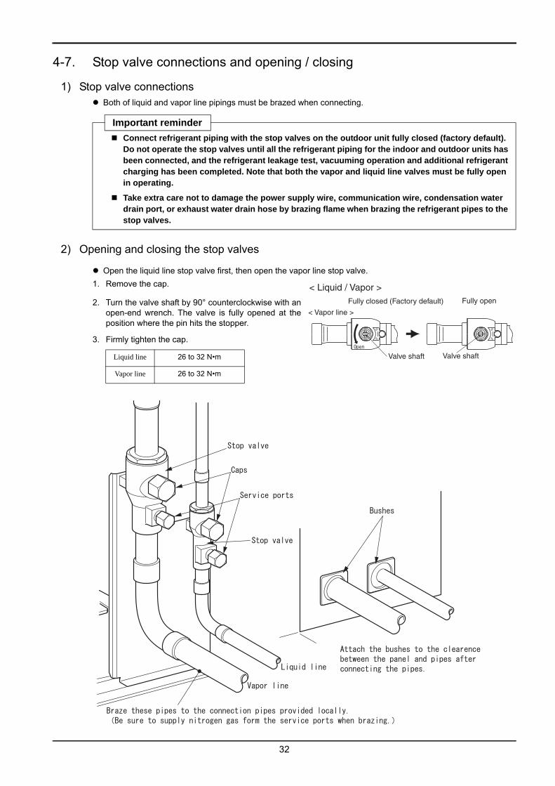
4-7. Stop valve connections and opening / closing
1) Stop valve connections Both of liquid and vapor line pipings must be brazed when connecting.
2) Opening and closing the stop valves
Open the liquid line stop valve first, then open the vapor line stop valve.1. Remove the cap.
2. Turn the valve shaft by 90° counterclockwise with anopen-end wrench. The valve is fully opened at theposition where the pin hits the stopper.
3. Firmly tighten the cap.
Important reminder
Connect refrigerant piping with the stop valves on the outdoor unit fully closed (factory default). Do not operate the stop valves until all the refrigerant piping for the indoor and outdoor units has been connected, and the refrigerant leakage test, vacuuming operation and additional refrigerant charging has been completed. Note that both the vapor and liquid line valves must be fully open in operating.
Take extra care not to damage the power supply wire, communication wire, condensation water drain port, or exhaust water drain hose by brazing flame when brazing the refrigerant pipes to the stop valves.
Liquid line 26 to 32 N•m
Vapor line 26 to 32 N•m
< Liquid / Vapor >
< Vapor line >
Fully closed (Factory default) Fully open
Valve shaft Valve shaft

33
4-8. Refrigerant vapor leakage test and vacuuming
1) Refrigerant vapor leakage test
1. Remove the service port caps of the stop valves. Connect the gauge manifold as shown in the illustrationbelow. Open V1, V2 and V3 and pressurize with nitrogen gas.
• Keep the stop valves closed. Always pressurize both the liquid and vapor pipings.
• The test pressure must be 37bar (3.7MPa) for standard GHP unit and 33bar (3.3MPa) for renewal GHP unit.
2. Slowly increase the pressure to the specified pressure. Do not increase the pressure quickly.a) Once 0.5 MPa is applied, hold the pressure and let stand for 5 minutes or more. Check that there is no pres-
sure drop.b) Next, increase the pressure to 1.5 MPa and again let stand for 5 minutes or more. Confirm that the pressure
does not drop.c) After that, increase the pressure to the specified value and note the ambient temperature and
pressure.d) Let stand at the specified pressure for one day. If there is no pressure drop, the system is OK.
If the ambient temperature changes by 1 Cº, the pressure changes 0.01 MPa accordingly. Judge if there isrefrigerant leakage taking account of temperature change before and after the leakage test period.
e) If a drop in pressure is detected through steps a-d, there is a leakage. Apply soapy solution to the weldedsections and flare joints to determine the leaking section’s locations and then fix them. Perform the leakagetest again once the leaks have been fixed.
Warning After the refrigerant piping has been installed, always perform a sealing test to confirm
that no refrigerant vapor is leaking. If the refrigerant should leak and the refrigerant vapor exceeds the limit concentration, it could cause an accident due to lack of oxygen.
Mai
n Un
it an
d Pi
ping
4. Refrigerant Piping

Elec
tric
alA
fter
Inst
alla
tion
Refe
renc
e
34
2) Vacuuming with a vacuum pump
Apply vacuuming at the both service ports of the liquid and vapor line stop valves.
【When there is a possibility of moisture intrusion in piping】① Increase the pressure to 0.05 Mpa with nitrogen gas after vacuuming for 2 hours or more.② Then, perform vacuuming again for 1 hour or more and make sure the pressure has reached -101 kpa.③ If the pressure does not reach -101 kpa after 2 hours of vacuuming, repeat steps ① and ② until the pressure
reaches -101 kpa.④ After the pressure has reached -101 kpa or lower, let stand for 1 hour and make sure that the pressure of the
vacuum gauge does not rise.
* Meaning of the possibility of moisture intrusion in pipingApply the procedure above when there is any possibility of internal condensation or rainwater intrusion insidethe refrigerant piping arising from long construction period during rainy weather like in the rainy season.
(Note) Keep the following points in mind, for this unit is an R410A model.
• To avoid cross-contamination with other types of oil, make sure to separate maintenance tools according tothe type of refrigerant used. In particular, never use the same gauge manifold and charge hose with otherrefrigerants (R22, R407C etc.).
• Use a backflow prevention adapter to prevent vacuum pump oil from entering the refrigeration system.
Important reminder
Vacuuming must be performed with the stop valves on the outdoor unit “fully closed”.
Do not perform an air purge with the refrigerant inside the outdoor unit or the refrigerant tank.
Use a vacuum pump which is able to attain pressure lower than -101 kpa (-755 mmHg).
<Operation Flow>Finish leakage test
Start vacuuming
Finish vacuuming
Charge refrigerant
Vacuum check
Continue operating the vacuum pump for 2 hours or more once the pressure has reached -101 kPa (-755 mmHg) or lower.
If the vacuum gauge needle rises, moisture remains in the system or there is a leakage. Determine the location of the leakage, fix, and reapply the vacuuming.
There must be no rise in the vacuum gauge needle after letting stand for 1 hour or more.
Vacuum gauge
Vacuum pump
Discharge
Charging hose
Charging hose Charging hose
Stopvalve
(fully closed)Low
pressureHigh
pressure
Gauge manifold
Outdoor unit
Stopvalve(fully
closed)
Service ports
Vapor line
Liquid line
Backflow prevention adapter

4-9. Refrigerant charging
Important reminder When charging the refrigerant, accurately measure the length of the piping and charge the proper
amount of refrigerant. If the amount of refrigerant is not proper, performance will decline or a breakdown could occur.
After completion of refrigerant charging, write down the installation record on the plate “POINTS FOR INSTALLATION” inside the outdoor unit control box panel. Besides, calculate the refrigerant amount for the whole system and write down the amount on the plate. Calculation formula is shown on the plate. (Write with a permanent marker so that the record does not disappear easily.)
1) Refrigerant charging amount
Always check the refrigerant gas factory charge on the unit label before calculating the amount to be added. Calculate the amount of refrigerant to be charged according to the following formula and liquid piping length for each size of the piping.
[When the GHP is connected to direct expansion indoor units]
Charge amount (kg)= ( 1 X 0.353) + ( 2 X 0.250) + ( 3 X 0.170) + ( 4 X 0.110) + ( 5 X 0.054) + ( 6 X 0.022) + Qde
Where Qde depends on the number of connected indoor units or the size of the AHU according to the table below. [When the GHP is connected to YOSHI AWS E1]
Charge amount (kg)= ( 1 X 0.353) + ( 2 X 0.250) + ( 3 X 0.170) + ( 4 X 0.110) + ( 5 X 0.054) + ( 6 X 0.022) + Qaws
1: Liquid piping ø 22.2 total length (m) 2: Liquid piping ø 19.1 total length (m) 3: Liquid piping ø 15.9 total length (m)
4: Liquid piping ø 12.7 total length (m) 5: Liquid piping ø 9.5 total length (m) 6: Liquid piping ø 6.4 total length (m)
Type of indoor system Qde [kg] Qaws [kg]
Direct expansion single indoor unit 5,5 -
Direct expansion multiple indoor unit 6,5 -
Direct expansion air handling unit AHU Refer to manufacturer specification -
Air water system YOSHI AWS - 1,5
2) Refrigerant charging method
Caution
When charging the refrigerant, be sure to wear a pair of leather gloves. If the refrigerant touches your skin directly, it may cause a frostbite.
Important reminder Always charge the refrigerant as a liquid in the tank. Charging as a vapor may cause a composi-
tional change of the refrigerant, and could result in a performance decline or a breakdown.
Always use a refrigerant scale when charging the refrigerant. Using a charging cylinder may cause a compositional change of the refrigerant, and could result in a performance decline or a breakdown.
To avoid cross-contamination with other oil types, make sure to separate maintenance tools according to the type of refrigerant used. In particular, never use the gauge manifold and charg- ing hose with other refrigerants (R22, R407C etc.).
35
Mai
n Un
it an
d Pi
ping
4. Refrigerant Piping

Elec
tric
alA
fter
Inst
alla
tion
Refe
renc
e
36
1. Place the tank (with the siphon pipeattached) on the refrigerant scale.
2. Remove the charging hose from thevacuum pump and connect it to thetank.
3. Perform an air purge of the inside ofthe charging hose from the tank to thegauge manifold.
4. Open the valves V1 and V3 and chargethe required amount of refrigerant inthe liquid phase. After the charging iscompleted, close the valves V1 andV3.
4-10. Refrigerant piping insulation and heat retention
Retain heat by applying insulating material separately to the vapor and liquid pipings.
Use insulating material with a heat resistance of 120 °C or more. After the refrigerant gas leakage test has beenperformed, use dressing tape to wrap the insulation.
.
4-11. How to secure refrigerant piping
If the antivibration mount is used, the distance to the first fixed point of refrigerant piping must be at least L = 1.5 m.
Caution As for refrigerant piping and drain piping, apply insulating material (polyethylene foam,
glass wool etc.) of 10 mm or more in thickness, to both of the vapor and liquid line pip-ings separately. When it exceeds DB 30 °C and RH 65 %, use thicker insulating material than above.Insufficient insulation work could cause household goods to get wet due to condensation water dripping.
Outdoor unit
Stop valve(fully closed)
Gauge manifold
Charging hose
Vapor line
Tank(with siphonpipe attached)
Stopvalve(fully
closed)
Liquid line
Charging hose
Vacuum pump Refrigerant scale
Exhaust
Charginghose
Service ports
Lowpressure
Highpressure
Backflow preventionadapter
Insulating material (heat resistance of 120 or more)
Vapor line piping (thick pipe)
Dressing tape(to prevent rain water from entering)
[Glass wool, polyethylenefoam, etc.]
Liquid line piping (thin pipe)
Insulating material (heat resistance of 120 or more)
Antivibration mount
Refrigerant piping
First fixed pointOutdoor unit L

37
[Combined installation]
Mai
n Un
it an
d Pi
ping
4. Refrigerant Piping

5. Fuel Gas Piping Installation
Warning
Use only the fuel gas indicated on the name plate. Using wrong type of fuel gas could cause incomplete combustion or could damage the out- door unit.
Always perform a gas leakage test after connecting the piping. In there should be a gas leakage, a fire or an explosion could occur.
Use soapy water or a gas leakage detector for performing the gas leakage test. Using a flame reaction test could cause a fire or an explosion.
Always use a reinforced gas hose between the gas valve on the fuel gas piping and outdoor unit. Failure to do so could cause a gas leakage.
Install the piping so that the fuel gas pressure at the inlet port of the outdoor unit is equal to the pressure required by the gas supply standard defined by the gas suppli- ers. Incorrect pressure of fuel gas could cause incomplete combustion or malfunction of the unit.
Important reminder Do not apply pressure of over 4.2 kPa when testing the fuel gas line for leakage. Doing so could
damage the regulator inside the unit.
The gas piping for the outdoor unit must be installed as shown below.
The device shown as 1 in the drawing below must be installed. This device is for servicing the fuel system.
Install the devices shown as 2 and 3 as necessary. These devices are for checking the supplied gas pressure and filtering the gas.
2 Pressure check cap
5 Reinforced flexible gas hose3 Strainer
4 External gas regulator(only when needed)
Rear side of outdoor unit
Fuel gas piping connection
1 Gas valve
38

39
6. Drain Piping Installation
1) Exhaust Water Drain Piping Installation
Condensation water from the exhaust gas comes out of the exhaust water drain hose of the outdoor unit. Con-nect the exhaust water drain hose to the drain piping as below.
Warning Never share the same pipe between the exhaust drain for the outdoor unit and the
exhaust water drain for the indoor unit.If exhaust gas flows into the building, it could cause gas poisoning or an accident due to lack of oxygen.
Arrange the piping so that the exhaust gas in the exhaust drain is released to the atmo-sphere in the following cases.a) The exhaust drain hose of the outdoor unit is connected to the catch basin or ditch with a lid. b) The exhaust drain water of the outdoor unit is released at the same location as the drain water of the indoor unit. If the exhaust gas is not released into the atmosphere, gas poisoning or an accident due to lack of oxygen could occur.
Caution When installing the outdoor unit on a roof, route the exhaust drain for the outdoor unit
to the drain for rainwater.Routing the exhaust drain directly onto the roof may stain the concrete or damage the water-proof sheet if fitted.
Important reminder
Extend the exhaust water drain piping to the appropriate outlet as shown on the following page, because condensation water from the exhaust gas comes out of the exhaust water drain hose of the outdoor unit.
Always provide downward gradient for the drain piping. Otherwise, the exhaust drain water will accumulate in the piping and damage the unit.
Take care not to clog up the end of the exhaust water drain hose when inserting the hose to the exhaust water drain pipe. Otherwise, the exhaust drain water will accumulate in the hose and damage the unit.
When the drain piping is a combined piping, provide openings (breathers) upstream of the con-necting points of the pipes to avoid back pressure.
Mai
n Un
it an
d Pi
ping
6. Drain Piping Installation

Elec
tric
alA
fter
Inst
alla
tion
Refe
renc
e
40
Important reminder in the cold district
[Installation]
Make antifreezing treatment on the exhaust water drain piping in the cold district (the area where the out-side air temperature can fall below 0 °C) to prevent drain water freezing. Drain water freezing will dam-age the unit.
Do not make antifreezing treatment on the pipe where the exhaust water drain hose is inserted. (See below.) Otherwise, the portion will overheat and damage the unit.
[Unit]
Install an exhaust water drain hose with heater (sold separately) in the cold district (the area where the outside air temperature can fall below 0 °C). Refer to the installation manual attached to the exhaust water drain hose with heater for installation method.
The cold district specification unit contains the exhaust water drain hose with heater in the engine com-partment. Be sure to pull out the hose from the outdoor unit referring to the installation manual attached to the hose. Failing to pull out the hose will damage the unit.
Exhaust waterdrain hose
Size at the end of the exhaustwater drain pipe:Hard PVC pipe VP30(VP50 for cold district specification)
Released to the atmosphere
Breather Breather
Rear side of outdoor unit
Catch basinExhaust water drain pipeDownward gradient must be 1/50 or more
Released to the atmosphere
Exhaust water drain pipe
Exhaust waterdrain hoses
Enlarged view
Exhaust waterdrain hosewith heater
Exhaust water drain hose
Exhaust water drain pipe
Released to the atmosphere
Do not make antifreezingtreatment here
Antifreezing treatment

41
2) Condensation water drain piping installation
Condensation water on the surface of the accumulator will drain from the condensation water drain port.Connect a hose on the market to the condensation water drain port and install the drain piping if there is a prob-lem due to condensation water dripping. In such a case, take appropriate measures such as fixing the end of thehose to prevent the condensation water from reaching the location where the condensation water causes theproblem. (If you connect the hose to the hard PVC pipe, prevent the hose from coming off the pipe.)
Avoid sharing the same pipe between the condensation water drain and exhaust water drain as much as possi-ble. If you need to share the same pipe between the condensation water drain and exhaust water drain, be sureto follow the following instructions when installing. Otherwise, exhaust gas could enter the outdoor unit andcause a breakdown.・The joint between the condensation water drain hose and exhaust water drain hose must be released to
the atmosphere. (Do not seal up the joint opening with the caulking material or other materials.)・Provide openings (breathers) upstream of the connecting points of the condensation water drain hose
and exhaust water drain hose.・Be sure to follow the instructions and precautions in “1) Exhaust water drain piping installation” on
page 38.
Rear side of outdoor unit
Hose on the market
Hard PVC pipe VP20 (SGP is acceptable)
Condensation waterdrain port ø15.8(SGP 16A)
Catch basin
Exhaust water drain hose
Rear side of outdoor unit
Breather
Joint Catch basinExhaust water drain pipe
Released to the atmosphere
Released to the atmosphere
Condensation waterdrain hose(Hose on the market:Locally procured)
Enlarged view of joint
Exhaust water drain pipe
Released to the atmosphere
Condensation waterdrain hose(Hose on the market:Locally procured)
Mai
n Un
it an
d Pi
ping
6. Drain Piping Installation

Elec
tric
alA
fter
Inst
alla
tion
Refe
renc
e
42
7. How to Extend Exhaust Pipe
Use stainless steel or polymer section pipes with a diameter of 100 mm for exhaust pipe extension.
Make sure the pipes for extension can withstand temperatures up to 120°C and acid condensed water.
1) Precautions for exhaust pipe extension
Try to avoid extending the exhaust pipe in areas where the outside temperature falls to 0 Cº or less because theinside of the exhaust pipe may freeze.
Warning Do not extend the exhaust pipe to a location where the exhaust gas could potentially
enter the indoors.If the exhaust pipe is extended to near the intake/exhaust port to the room, window or ventila-tion port, the exhaust gas could flow into the room and cause gas poisoning or an accident due to lack of oxygen.
Do not extend the exhaust pipe to an area where flammable gas can be produced, flow into, accumulate or leak, or where volatile flammable materials can be treated. Extension to such locations could result in a fire or an explosion.
Be sure to discharge the exhaust gas directly to an outdoor area open to the atmo-sphere. Accumulated exhaust gas could cause gas poisoning or an accident due lack of oxygen.Install the outdoor unit where adequate ventilation is provided.
Be sure to discharge the exhaust gas to the atmosphere where the gas causes no adverse effect to the surroundings.If the exhaust gas is exhausted into the catch basin or ditch, it could be drawn into the room and cause gas poisoning or an accident due lack of oxygen.
Be sure to discharge the exhaust gas to a location where the exhaust gas is not directed toward animals or plants.Exposure to the exhaust gas or discharge air could have harmful influence on animals or plants.
Be sure to maintain the appropriate clearance from the flammable or flame resistant material covering building in accordance with the following figure.Inadequate clearance could cause a fire.
• Distance from the exhaust pipe must be as follows.
• Distance from the top end opening of the exhaust pipe must be as follows.
Space
Without heat inslation With heat inslation
or more
Exhaust pipe
Exhaustpipe
Must not contact
or more Insulating material20 mm or more in thickness
Must not contact
Bottom
150 or more
300 or more
150 or more
150 or more300 or more
600 or more
Exhaust pipe top
Length: (mm)

43
2) Exhaust pipe extension
Extended the exhaust pipe according to the following procedure by referring to the figure below.
1. Remove the exhaust top from the outdoor unit exhaust port.
2. Connect the extra sections sequentially from the outdoor unit side, and extend the exhaust pipe to thedesired position following the restriction below.
• Total length of the exhaust pipe extension shall not exceed 15 m.
• Total number of exhaust pipe bends (bending angle = 90 °) shall not exceed 5 (each equivalent lenght 1m).
• The extended pipe shall be anchored to the building or similar structure with fixing brackets every 1.5 to 2 m.
• The exhaust pipe shall not be gathered or connected with the other exhaust pipe.
3. Attach the exhaust top at th outlet of the extended exhaust pipe paying attention to the following:
• The angle of the exhaust vent plane shall be vertical to the ground by adjusting the elbow pipes so that rain-water may not enter the exhaust pipe directly.
• Apply silicone caulking material at the lower part of the metal mesh in accordance with the following figure sothat the drain water may not drip from the exhaust top. (Refer to the figure below.)
• When installing the outdoor unit on the antivibration mount, the extended exhaust pipe may come off due tothe vibration. In such a case, the only acceptable extension is the following.
3) Installation check
Make sure that there is no leakage of exhaust gas or exhaust drain water form the exhaust pipe joints by per-forming test operation after completing the exhaust pipe extension.
Elbow
Exhaust topType 300 straight pipe ortype 200 slide pipe
Mai
n Un
it an
d Pi
ping
7. How to Extend Exhaust pipe

Mai
n Un
it an
d Pi
ping
Aft
er In
stal
latio
nRe
fere
nce
44
8. Summary of Electric Wiring Installation
8-1. Opening for power supply wires / signal wires
Warning Use a dedicated branch circuit. Never use the outdoor unit with other appliances on the
same circuit. If the outdoor unit and other appliances are used on the same circuit, secondary damage could occur due to breaker tripping.
All electrical installation work must be performed by a certified electrician in accordance with the relevant local and national regulations, technical standards, and instructions pro-vided in this manual.Improper installation could result in electrical shock, fire or other hazards.
Provide an electric leakage breaker with the specified capacity for each outdoor unit (sensitivity amperage is 30 mA). If the electric leakage breaker is not installed, electrical shock could occur.
Provide an over-current breaker with the specified capacity for each outdoor unit. If the proper over-current breaker is not installed, overheating, fire or secondary damage due to the breaker tripping could occur.
Always use the designated cable for wiring. Make sure that the cable is properly con-nected and fixed so that the outside forces may not be transferred to the terminal connec-tion.Improper connecting or fixing can result in overheating, fire or other hazards.
Always ground the unit in accordance with the relevant technical standards.Improper grounding can result in electrical shock.
Important reminder
Select an “inverter type” electric leakage breaker that will not be affected by high-frequency leakage currents.

8-2. Wiring example (AC 230V single phase)
AC 2
30 V
sin
gle
phas
e
16 A
bre
aker
over
curre
nt+
earth
leak
age
(not
supp
lied)
Indo
or u
nit
Indo
or u
nit
R/C
–w
ired
rem
ote
cont
rolle
ror
wire
less
rem
ote
cont
rolle
r rec
eive
r
L N
F1 F
2In
–Out
R/C
P1 P
2L
N
F1 F
2In
–Out
R/C
P1 P
2
L N
F1 F
2F1
F2
+
-
Mas
ter O
utdo
or u
nit
P1 P
2
In–O
utO
ut–O
ut
Con
nect
ion
betw
een
outd
oor u
nits
and/
or c
entra
lrem
ote
cont
rolle
r (no
pol
arity
)
AC 2
30 V
sin
gle
phas
e
32A
–C
cla
ss–
brea
ker
over
curre
nt+
earth
leak
age
(not
supp
lied)
Hot
wat
er c
ircul
atio
npu
mp
ON
OFF
con
tact
(whe
repr
ovid
ed)
P.ki
t
DIR
EC
T E
XP
AN
SIO
N C
OM
BIN
ED
GH
P I
ND
OO
R S
YS
TE
M W
IRIN
G
Mul
tiQ
1 Q
2L
NF1
F2
F1 F
2+
-
Dep
ende
ntO
utdo
or u
nit
In–O
utO
ut–O
utP.
kit
Mul
tiQ
1 Q
2
Hot
wat
er c
ircul
atio
npu
mp
ON
OFF
con
tact
(whe
repr
ovid
ed)
Con
nect
the
cent
ralis
edre
mot
e co
ntro
lun
itor
ada
pter
toth
e ou
tdoo
r –ou
tdoo
r sig
nalw
ire.
Impo
rtant
rem
inde
r
In –
Out
: com
mun
icat
ion
line
indo
or u
nit–
outd
oor u
nit
Out
–O
ut: c
omm
unic
atio
nlin
eou
tdoo
r uni
t–ou
tdoo
r uni
tand
/or c
entra
lrem
ote
cont
rolle
rM
ulti:
com
mun
icat
ion
line
mas
ter o
utdo
or u
nit–
depe
nden
tout
door
uni
t
/d
/d
45
Elec
tric
al
8. Summary of Electric Wiring Installation

AC 230 V single phase
16 A breakerover current + earth leakage
(not supplied)
Indoor unit Indoor unit
R/C – wired remote controlleror wireless remote controller receiver
L N
F1 F2In–Out
R/CP1 P2 L N
F1 F2In–Out
R/CP1 P2
L N F1 F2 F1 F2 + -
Outdoor unit
P1 P2
In–Out Out–Out
Connection between outdoor unitsand/or central remote controller (no polarity)
AC 230 V single phase
20A – C class – breakerover current + earth leakage
(not supplied)
Hot water circulation pumpON OFF contact (where provided)
P.kit
DIRECT EXPANSION INDOOR SYSTEM WIRING
MultiQ1 Q2
Connect the centralised remote control unit or adapter to the outdoor – outdoor signal wire.
Important reminder/d
/d
In – Out: communication line indoor unit – outdoor unit Out – Out: communication line outdoor unit – outdoor unit and/or central remote controller
L N F1 F2 F1 F2 + -
Outdoor unit
1 3
H/C CP ON
1 2
CHECK
1 2
AC 230 V single phase
16 A breakerover current + earth leakage
(not supplied)
AC 230 V single phase
20A – C class – breakerover current + earth leakage
(not supplied)
AIR WATER SYSTEM WIRING
In–Out Out–Out P.kit
Hot water circulation pumpON OFF contact (where provided)
GHP operation signal(dry contact)
Multi
Q1 Q2/d
/d
AWS
L N F1 F2C. H/CGHP CHK SET
+ -AL OUT
1 2 GHP – AWS
System failure(dry contact)
CAP+ -
Remote capacitycontrol 4-20 mA
Remote set pointcontrol 4-20 mA
In – Out: communication line indoor unit – outdoor unit Out – Out: communication line outdoor unit – outdoor unit and/or central remote controller
46

iping P
and
Unit in a M
nstallation I er t f A
e
en
c r e Ref
Elec
tric
al
9. Electric Wire Specifications and Precautions
9. Electric Wire Specifications and Precautions 9-1. Power supply wire
Warning
The specifications for the electrical wiring and the selection of the appropriate size
must be in accordance with the relevant local and national regulations and technical standards. Improper wiring can result in overheating, short circuit or fire.
Use copper conductors only. Always install a C class circuit breaker before the GHP outdoor unit. Use insulated wire for the power cord.
Select the power supply cable type and size in accordance with the relevant local and national regulations and technical standards.
Specification for local wiring are in compliance with IEC60245.
Always ground the unit in accordance with the relevant technical standards. Use a ground wire of ø 2.0 mm or more secured to the designated grounding screw.
Use M4 crimp terminals to connect wires to the terminal block.
Select the power supply wire size in accordance with following table.
Power supply for one outdoor unit (Indoor unit has separate power supply) *Stand-alone installation or when each of the combined units has power supply from the separate branch circuit.
C class circuit breaker Power supply wire Outdoor
unit Power supply Rated current overcurrent protection
Sensitivity current earth leakage protection
Minimum thickness
Maximum line length ※
P450
P560 36 (24 m)
P710
Single phase 230 V AC
20 A 0,03 A 3.5 mm2
28 (22 m)
※ Select the figure in ( ) when high static pressure mode is selected.
Power supply for one outdoor unit (Indoor unit has separate power supply) *When both of the combined units have power supply from the same branch circuit. (This table is applied to the wir- ing for the current for 2 outdoor units.)
C class circuit breaker Power supply wire Outdoor
unit Power supply Rated current overcurrent protection
Sensitivity current earth leakage protection
Minimum thickness
Maximum line length ※
P450/ P560 x2 18 (13 m)
Other than above
Single phase 230 V AC
32 A 0,03 A 3.5 mm2 14 (11 m)
※ Select the figure in ( ) when high static pressure mode is selected.
The values in the upper table are reference based on Japanese regulation. Follow the relevant local and national regulations and technical standards. The maximum line length in the table above makes voltage drop 2%. If the length exceeds the value shown above, review the wire thickness.
Install an over-current breaker and an electric leakage breaker to each outdoor unit in accordance with the table above and install wiring. 2 outdoor units can have power supply from the same branch circuit only when the both units are combined
The power supply wire of the indoor units must be taken from the branch circuit exclusively for the indoor units. Follow the wiring procedure described in the installation manual attached to the indoor units with regard to the power supply wiring, the over-current breaker, and the electric leakage breaker to be connected to the indoor units.
47

48
9-2. Signal wire between indoor-outdoor units, outdoor-outdoor units, andbetween combined outdoor units
Signal wires between indoor-outdoor units, between outdoor-outdoor units, and between combined outdoorunits have no polarity.
The length of the signal wires between indoor-outdoor units and outdoor-outdoor units must not exceed the fol-lowing:
• Longest wiring length: 1000 meters
• Total wiring length: 2000 meters
The length of the signal wire between combined outdoor units must not exceed 30 meters.
Use M3 crimp terminals to connect wires to the terminal block.
Be sure to use vinyl sheathed wire or cable with 2 cores for signal wire in accordance with the relevant local andnational regulations and technical standards.
Important reminder
Never mix signal and power supply (230 V) wires in a multiple core cord. This will cause malfunc-tion. In addition, provide 50 mm or more clearance between wires to prevent electrical noise influ-ence.
Always use shielded wire when installing the outdoor unit near high-frequency medical equip-ment, high-frequency welding equipment or any other equipment that generates high-frequency waves. Otherwise, malfunction could occur due to high-frequency waves.
When using shielded wires, always ground just one side. Otherwise, communication problem could occur.
Never use multiple core wires having 3 or more cores.
Wire thickness must not exceed the range between 0.75 mm2 to 1.25 mm2.
Do not bundle signal wires.
Arrange the signal wires apart from the power supply wires so that the signal wires meet the fol-
lowing condition to eliminate electrical noise influence.
Power supply wire(230 V)
Power supply wire(230 V)
Signal wire
Signal wire
Wrong Correct
CordCordMultiple core cord
50 mmor more
* Because this system generates very little noise, isolation distance of 50 mm or more is enough.
Capacity of power sourceIsolation distance between power supply and signal wires (mm)
This system Other equipment
230 V or less
10 A or less
50 mm or more *1
300 mm or more
50 A or less 500 mm or more
100 A or less 1000 mm or more
Over 100 A 1500 mm or more

Mai
n Un
it an
d Pi
ping
Elec
tric
alA
fter
Inst
alla
tion
Refe
renc
e
49
9. Electric Wire Specifications and Precautions
9-3. Remote control wire Connect terminals of the remote control wire (P1,P2) to the indoor unit terminals (P1,P2) (P1 and P2 terminals
have no polarity).
Wire specifications
Peel the sheathed part of the wire passing through the inside of the remote controller case.
Type of wire Vinyl sheath code or cable
Thickness 0.75 to 1.25 mm2
Important reminder
When installing the wiring, be sure to keep signal wires away from the power supply wires so that the signal wires are not affected by electrical noise (external noise).
Peel the seathed part

50
10. Power Supply Wiring Procedure
10-1. Wiring instruction
[Combined installation]
●Be sure to wire for every refr igerant piping system.
Indoor-outdoor unit signal wire
Point ④
System ①
System ②
● In order to avoid at taching 3 wires to the terminal , connect the wire f rom the terminal uni t of the outdoor and outdoor uni t wir ing.
I f there is a branching, use a relay terminal .
I : InO : OutRC: Remote controller Single-phase
230 VAC Power supply
Outdoor unit A(Master unit)
Outdoor unit B(Dependent unit)
Outdoor unit C(Master unit)
Outdoor unit D(Dependent unit)
■Maximum number of the connectable indoor units on a network is 128. ■Signal wires between the indoor units of the same refrigerant system must be connected to the In-Out terminal of the outdoor unit in the same system. It cannot be connected to the Out-Out terminal, or an outdoor unit in the different system.
F1 F2
F1F2
F1 F2Multi MultiQ1Q2
F2F1 F2F1
Q1 Q2
F1 F2 F1 F2 Q1Q2 Q1Q2
F2F1
F2F1 F2F1 F2F1
Point ①● All of indoor-outdoor and outdoor-outdoor unit signal wires must be non-polarity 2 core cable.
Point ②
●Signal wire between refr igerant piping systems.●Maximum number of the connectable refr igerant p ip ing systems is 10.
Outdoor-outdoor unit signal wire
● In Combinat ion Mult i , the master uni t controls the dependent uni t . Connect the indoor- outdoor and outdoor- outdoor s ignal wires to the master uni t , not to the dependent uni t . Connect the Combinat ion Mult i s ignal wires between the master and dependent uni ts.
Point ③
Point ⑤
Power supply
Centralized control unit
Single-phase230 VAC Power supply
Single-phase230 VAC Power supply
Single-phase230 VAC Power supply
Indoor unit
Remote controller
Single-phase230 VAC Power supply Indoor unit
Remote controller
Important reminderTo the other system
I・O O・O
I・O I・O I・ORC RC RCP1 P2
P1 P2 P1 P2
P1 P2 P1 P2
MultiI・O O・O
I・O I・O I・ORC RC RC
P1 P1P2 P2
P1 P2P1 P2 P1 P2

Mai
n Un
it an
d Pi
ping
Elec
tric
alA
fter
Inst
alla
tion
Refe
renc
e
51
10. Power Supply Wiring Procedure
[Stand-alone installation]
Important reminder
Do not connect the indoor-outdoor unit signal wires of a different system. Doing so could result in improper operation.
Refer to the “Technical guide book” for the details of the indoor and outdoor unit, centralized con-trol unit and adapter connectable to the network.
System
System
In order to avoid at taching 3 wires to the terminal , connect the wire f rom the terminal uni t of the outdoor and outdoor uni t wir ing.
I f there is a branching, use a relay terminal .
To the other system
All of indoor-outdoor and outdoor-outdoor unit signal wires must be non-polarity 2 core cable.
RC RC RC
RC RC
Point
Point
Be sure to wire for every refr igerant piping system.
Indoor-outdoor unit signal wire
Point
Signal wire between refr i - gerant piping systems.
Maximum number of the connectable refr igerant p ip ing systems is 10.
Outdoor-outdoor unit signal wire
PointImportant reminder
Maximum number of the connectable indoor units on a network is 128. Signal wires between the indoor units of the same refrigerant system must
be connected to the In-Out terminal of the outdoor unit in the same system. It cannot be connected to the Out-Out terminal, or an outdoor unit in the different system.
Single-phase230 VAC Power supply
Single-phase230 VAC Power supply
Single-phase230 VAC Power supply
Remote controller
Indoor unit
Remote controller
Outdoor unit C(Master unit)
Outdoor unit A(Master unit)
Single-phase230 VAC Power supply
Power supply
I : InO : OutRC: Remote controller
Centralized control unit
Indoor unit
RC

52
10-2. Wiring length
The wiring length of indoor-outdoor and outdoor-outdoor signal wires except the wiring of the remote controllermust not exceed the following restriction:
• Longest wiring length: 1000 meters
• Total wiring length: 2000 meters (When using shielded wires, the total wire length is restricted up to 1500 meters.)
System example
Signal wire length between combined outdoor units
Signal wire length between combined outdoor units must be 30 m or less.
Important reminder
Be sure to check the longest wiring length and the total wiring length at the time of designing.When the length exceeds the acceptable restriction range, consider dividing the system or install-
ing a D Ⅲ -NET extension adapter (sold separately) additionally.
400 m between and
200 m between and
In the above system, the longest wiring distance is 900 m between and , which satisfies the longest wiring length limit of 1000 m. And the total length, which is the total of 900 m between and , and 200 m between and is 1100 m. This also satisfies the total wiring limit of 2000 m. The system functions properly only when both the longest wiring length and the total wiring length are within the limit as shown above.
Outdoor unit
Outdoor unit
Outdoor unit
700 m between and900 m between and
ON/OFF controller
Central remotecontroller

Mai
n Un
it an
d Pi
ping
Elec
tric
alA
fter
Inst
alla
tion
Refe
renc
e
53
10. Power Supply Wiring Procedure
10-3. Branch wiring
The following 3 wiring methods are acceptable.
Series wiring
Bus wiring (Up to 10 branches, re-branching after the branch is not possible)
Star wiring (Up to 10 branches, re-branching after the branch is not possible)
Centralized controller
Series wiring
First branch
Second branch
Third branch
Bus wiring
Centralized controller
First branch
Second branch
Third
bra
nch
Star wiring
Note) Although the above figures show the examples using the centralized controller, the same wiring system can be used with other centralized control devices.
Centralized controller

11. Various Function Settings
All function settings of the outdoor unit in this model can be performed through board maintenance function by AISIN authorised personnel.
11-1. Address setting method of the indoor and outdoor units
The address setting of the outdoor and indoor units is performed automatically.
When the centralised remote controller is added, set the group address to the indoor units with the standard remote controller. If the standard remote controller is not installed provide that the service centre brings a spare one to set the group address on each unit.
11-2. EEP dip switch setting
This model has EEP dip switches inside the outdoor unit circuit board. Refer to “List of EEP dip switch settings” on the following page for the contents of the switches and the factory default setting .
Warning
Be sure to change the #4 pin of #1 EEP dip switch 1 to “ON” when the catalyser is installed. If not, the protection device may operate improperly and smoke, fire or malfunction could occur.
Caution
Do not touch the moving parts (fans or belt around the engine). You could be caught by the moving parts and be injured. The fans or engine may automatically start running to protect the device to maintain perfor- mance even if the GHP is stopped. Be sure to turn OFF the power breaker when you need to touch the moving parts.
54

e
en
c r e Ref
ipin
g P
and
Unit in a M
trical
Elec
11. Various Function Settings
List of EEP dip switch settings
EEP dip switch
Pin No. Functions Other Factory default
1 Periodic inspection display OFF: Not available / ON: Available ON 2 Not in use OFF
3 Snow blowing function *1 OFF standard spec. ON Cold district spec.
4 Exhaust gas temperature for catalyser *2
OFF standard spec. ON catalyser spec.
5 Conditional silent mode OFF 6 Energy saving mode
OFF: Not available / ON: Available
OFF
7 Combination Multi backup function *3
OFF: Backup starts after error reset On: Automatic backup
OFF standard spec. ON combination multi spec.
1
Setting can be changed with check code
No.80
8 Not in use OFF
1 Setting of cool / heat switching OFF: Indoor unit / ON: Outdoor unit OFF unit for DX ON unit for AWS
2 OFF ON OFF ON ON 3
Master control *3 OFF
Prohibited OFF
Master collective ON
Dependent collective ON
Individual setting ON
4 OFF 5 OFF 6 OFF 7 Outdoor fan high static
pressure mode OFF: Not available / ON: Available OFF
2
Setting can be changed with check code
No.81
8 Connection of AHU kits OFF: Not available / ON: indoor unit capacity
higher than 28 kW OFF DX and AWS
ON AHU 1 Reserved area *4 ON 2 OFF 3 Reserved area *4 Depends on models 4 Reserved area *4 Depends on models 5 Reserved area *4 Depends on models 6 OFF 7 OFF
3
Setting can be changed with check code
No.82
8 OFF
*1 This setting is “ON” only when the outdoor unit is cold district specification. Change this setting to “ON” in the cold district or heavy snowfall area.
*2 This setting is “ON” only when the deodorizing catalyst is installed. Be sure to change this setting “ON” when installing the deodorizing option.
*3 As for Combination Multi type, the setting of the master outdoor unit (outdoor unit with the outdoor-indoor com- munication wires connected) is reflected on this unit’s operation.
*4 Do not rewrite this data. Failure to follow this prescription may result in improper operation or damage of the unit.
55
Afte
r Ins
talla
tion

56
EEP dip switch setting is set in the “check mode“. Disconnect the personal computer, and then, select the checkmode.
1) How to change the current mode to the check mode
1. Press the MODE SELECT switch. The mode LED (LED15) lights up in green.(Proceeding to the monitoring mode)
2. Press and hold the SET and CLEAR switches at the same time. The mode LED (LED15) lights up in red.(Proceeding to the check mode)
* You can not proceed to the check mode within 20 seconds after turning the power on, or during system opera-ton.
* You can not proceed to the check mode while the remote controller is on.
2) Changing EEP dip switch settings
1. Press the CODE No. UP or CODE No. DOWN switch to select the check code No. 80 to 84 as follows. (Refer to “List of EEP dip switch settings” on the previous page for the details about EEP dip switch function.)
2. Select the switch pin number by pressing the INDOOR SELECT switch.
(You can change the display as 1 → 2 →・・・→ 8 → 1 each time you press the switch.)
3. Press the SET switch. LED1 and LED2 start to flash. At this time, on/oF setting can be changed by pressing theCODE No. UP or CODE No. DOWN switch.(Each press of either CODE No. UP or CODE No. DOWN switch changes the setting between on and oF.)
4. After selecting oF or on, press the SET switch to input the current setting. The display returns to lighting.
* If you press the CLEAR switch while the display is flashing, you can return the display to lighting up withoutinputting the current setting.
Display when the setting is OFF
Display when the setting is ON
LED6
SW1CODE No.UP DOWN
SW2 SW3 SW4 SW5 SW6INDOORSELECT
MODESELECTCLEAR SET
Code No. Switch pin No. ※oF means OFFon/oF statusLED5 LED4 LED3 LED2 LED1
SW1CODE No.UP DOWN
SW2 SW3 SW4 SW5 SW6INDOORSELECT
MODESELECTCLEAR SET
LED6 LED5 LED4 LED3 LED2 LED1

e
en
c r e Ref
ipin
g P
and
Unit in a M
trical
Elec
Aft
er In
stal
latio
n
11. Various Function Settings 11-3. Gas type setting
Warning
■ Gas type selection must be changed by AISIN Authorised Technical Service Centre qualified personnel. Factory settings are chosen depending on the GHP version. Failure to observe this prescription makes the warranty no longer valid.
■ If, by any chance, changing the gas type setting is necessary, please contact with the AISIN Authorised Technical Service Centre.
■ The installation of catalyser and further components may be needed when changing gas type to LPG. Please contact with the AISIN Authorised Technical Service Centre.
Gas type setting is set in the “check mode“. Disconnect the personal computer, and then, select the check mode. To select the check mode, refer to “12-2. 1) How to change the current mode to the check mode“ on the previous page. The AISN GHP can work with several supply gas types. Gas type can be chosen by adjusting one setting of the outdoor unit PC. In some cases it can be necessary to install a catalyser and/or replace the gas mixer.
1) How to set the gas type
1. Press the CODE No. UP or CODE No. DOWN switch and select the check code No. 76 as follows.
Code No. Gas type
LED6 LED5 LED4 LED3 LED2 LED1 ※ When 13A is selected.
SW 1 SW2 SW3 SW4 SW5 SW6
CODE No. UP DOWN
INDOOR SELECT
MODE SELEC
CLEAR SET
2. Press the SET switch. LED1 to LED4 start to flash. At this time, the gas type can be changed by pressing the CODE No. UP or CODE No. DOWN switch. (Refer to the following table for the details about the gas type). If you press the CLEAR switch while the display is flashing, you can go back to the previous screen without changing the gas type.
Display Gas type 13 A NATURAL GAS G20 (H erdgas) 12 A NATURAL GAS G25 (L erdgas)
iPro※ LPG (G30/G31) H or E Not in use
3. After selecting the gas type, press and hold the SET switch to input the current setting. The display stops
blinking and the selected gas type is shown. 4. Exit the check mode by pressing the MODE key for more than three seconds. The indoor unit recognition
procedure starts back.
※ Propane – Butane mixtures are allowed up to 70% Propane and 30% Butane. Other mixtures, outside the indicated range, are not allowed. When changing gas type to LPG, it is compulsory to install the optional catalyser kit to be ordered separately.
Installation of the external gas regulator
Whereas the supply gas pressure was higher than the prescribed one, indicated on the AISIN GHP plate, or anyway LPG (G30/G31) is used as supply gas, install an external gas regulator, such as the on described in the figure. (eg. Madas model RG/2MTA DN 20 20 – 60 mbar or similar, CE marked, EN88 compliant).
57

58
11-4. Field settings with the remote controller
Master control setting
What is master control?Only master remote controller can select “cooling”, “heating”, and “dry”.
How to set master controlA remote controller you press the “OPERATION CHANGE / MIN-MAX” button first after installation of the indoor/ outdoor unit is the master controller.
How to change the master controllerTo change the master controller, refer to “SETTING THE MASTER REMOTE CONTROLLER” in the operationmanual attached to the indoor unit.
Field setting
Setting procedure
1. In the normal mode, press the button for 4 seconds or longer. The mode changes to the “field setting
mode”.
2. Press the button and select the “mode number” to set.
3. When setting each indoor unit under group control (when selecting 20, 22, 23 and 25 mode numbers), press
the button and select the “indoor unit number” to set. (This step is not required at the time of group set-
ting.)
4. Press the up button to select “First code number”.
5. Press the down button to select “Second code number”.
6. To input current setting changes, press button once.
7. Press the button for about 1 second. The mode returns to the “normal mode”.
(Example) To set the filter sign display interval to “Filter contamination-Heavy” at the time of group setting, selectthe mode number “10”, first code number “0” and second code number “02”.
ON/ OFF
SETTING
Field settingmode
Mode No.Second code No.
First code No.
3
1 7
4
5 2
6

Mai
n Un
it an
d Pi
ping
Elec
tric
alA
fter
Inst
alla
tion
Refe
renc
e
59
11-5. List of setting contents and mode numbers
Mode No.*1
First code No.
Description of contentsSecond code No. *2
01 02 03 04
Set
ting
at i
ndoo
r un
it s
ide
10(20)
0
Filter contamination - Heavy/Light(Setting of filter sign display interval for cleaning)j(Setting to reduce displaying period to half when filter contamination is heavy.)
Ultra-long-life type
Ligh
t
Approx. 10,000 H
Hea
vy
Approx. 5,000 H
- -Long-life type Approx. 2,500 H Approx. 1,250 H
Standard type Approx. 200 H Approx. 100 H
1Long-life filter type(Setting of filter sign display interval for cleaning) (Change setting when ultra-long filter is installed)
Standard (long-life filter) Ultra-long life filter - Oil guard filter
2 Thermostat sensor in remote controller *3
Use both the unit sensor (or remote sensor if installed) AND the remote controller sensor.
*5+6
Use unit sensor only (or remote
sensor if installed). *5+6
Use remote con-troller sensor only.
*5+6-
3 Display of air filter cleaning sign (To be set when not setting filter cleaning sign)
Display Not display - -
5 Information to I-manager, I-touch contoroller
Only unit sensor value (or remote sensor value if
installed).
Sensor value as set by 10-2-0X or
10-6-0X.- -
6 Thermostat sensor in group controlUse unit sensor only (or remote sensor if
installed). *6
Use both the unit sensor (or remote sensor if installed) AND the remote controller sensor.
*4, 5, 6
- -
12(22)
0 Output signal X1-X2 of the optional adopter; KRP1B PCB unit
Indoor unit thermo-ON +
compressor run- Operation Malfunction
1ON/OFF input from outside (T1/T2 input)(Setting for when forced ON/OFF is to be operated from outside).
Forced OFF ON/OFF operation - -
2 Thermostat differential changeover (To be set when using remote sensor) 1 ℃ 0.5 ℃ - -
3 Fan setting during thermostat OFF at heating operation (For capacity increase of air cleaning unit) LL Set speed OFF*7 -
4 Differential automatic changeover 0 ℃ 1 ℃ 2 ℃ 3 ℃ *8
5 Automatic re-start after power failure(Return to the status before the blackout) Disabled Enabled - -
13(23)
0 Setting for ceiling height (for AXAP model; setting for air flow rate) *9 Standard High ceiling 1 High ceiling 2 -
1 Selection of air flow direction (To be set when installing a blocking pad kid) 4-way flow 3-way flow 2-way flow -
3 Air flow direction selecting function (To be set when attaching decorative panel to air outlet) Equipped Not equipped - -
4 Air flow direction range setting Upper Normal Lower -
5 Setting of fan speed (Control with the air outlet at the time of phase control)
Standard Option 1 Option 2 -
15(25) 3 Drain pump operation with humidifying Not equipped Equipped - -
11. Various Function Settings

Second code No. *2 Mode No.
*1
First code
No.
Description of contents 01 02 03 04
0 Permission level setting Level 2 Level 3 - -
1 Leave home function Not permitted Permitted - -
1b
2 Thermostat sensor in remote controller (For limit operation and leave home function only)
Use
Not use
-
-
*1 Each mode setup is programmed in the group mode. When setting individually by each indoor unit, select the mode number in () in the table. However, the current setting status only can be confirmed individually by selecting the number in (). In a group set- ting, even though all of the second code numbers are selectable, a display on the LCD remains in 01.
*2 The second code number settings at the factory depend on indoor unit types. For more details, refer to the installa- tion and operation manual attached to each indoor unit.
*3 When the remote controller cannot be installed in a living space, thermostat sensor in the remote controller must be set to “Not use (10-2-02)”.
*4 If group control is selected and the remote controller sensor is used, then set 10-6-02 & 10-2-03.
*5 If setting 10-6-02+10-2-01 or 10-2-02 or 10-2-03 are set at the same time, then setting 10-2-01, 10-2-02 or 10-2-03 have priority.
*6 If setting 10-6-01+10-2-01 or 10-2-02 or 10-2-03 are set at the same time for group connection, 10-6-01 has priority and for individual connection, 10-2-01, 10-2-02 or 10-2-03 have priority.
*7 Only use in combination with optional remote sensor or when setting 10-2-03 is used. *8 More settings are: Second code No.; 05 / 4 ℃ , 06 / 5 ℃ , 07 / 6 ℃ , 08 / 7 ℃ .
*9 Refer to the following chart “Rough guide of a setup for high ceiling application” for more details. * Do not make any settings not given in the table. * Not displayed if the indoor unit is not equipped with that function. * When returning to the normal mode, “88” may be displayed in the LCD in order for the remote controller to initialize
itself. * Depending on an operation status, setting of fan speed may be different from actual fan speed. * It is not possible to change field settings on the remote controller that is set to “sub”.
60

Mai
n Un
it an
d Pi
ping
Elec
tric
alA
fter
Inst
alla
tion
Refe
renc
e
61
12. Remote Control
12-1. Remote control with 2 remote controllers
1 indoor unit control with 2 remote controllers at 2 locations
A later command by either of the remote controllers can override the previous command by either one to con-trol the indoor unit operation.
Only the thermostat in the main remote controller is recognized by the indoor unit when installing 2 remote con-trollers.
To set the remote controllers to main or sub. remove the front panels of the remote controllers and set the main/sub changeover switches on the PC boards to “Main” or “Sub“. “Field settings with the remote controller” can set only the main remote controller.
12-2. Group control
Simultaneous control of up to 16 units with 1 remote controller
Because remote control wiring for group control has no polarity, P1 and P2 can be switched.
All indoor units within the group have the same setting, and each indoor unit is controlled individually by its own built-in thermostat.
At the time of group control, remote controller thermostat is set to “Not use” automatically.
Because the address is set automatically, address setting by the remote controller for group control is not nec-essary.
From other indoor units
Single-phase 230 VACpower supply
To other indoor units
External input
Remote control wiring length is up to 500m.
Mainremotecontroller
Sub remotecontroller
MainSub
MainSub
Note)If the main and sub remote controllers equipped with thermostat sensors are mounted in separate rooms, set the main remote controller thermostat to “Not use” when performing field setting with the remote controller.
Indoor unit
Remote controller
Remote controller wiring length is up to 500m.
Note)This diagram shows remocontrol wiring only.
12. Remote Control

62
13. Test Operation
13-1. Before starting test operation
1. Turn ON the main power supply and the electric leakage breaker inside the outdoor unit’s control box at least 6hours before the test operation to energize the compressor heater.
2. Be sure to fully open the stop valves of the outdoor unit for both liquid and vapor pipes. (Open the liquid stopvalve first, and then open the vapor stop valve.)
3. Open the fuel gas valve.
13-2. Process of the outdoor unit when turning on the power
At the time of initial power supply, the system will first perform power master setting and address setting (outdoorand indoor address). Therefore, wait for up to 15 minutes until the unit starts operation.
Be sure to perform test operation after turning on the power when you turn on the power at the first time.
The following shows the procedure form turning on the power to completion of connection check.
Caution Do not touch the moving parts.
You could be injured.The fans or engine may automatically start running to protect the device to maintain perfor-mance even if the GHP is stopped.Be sure to turn OFF the power breaker when you need to touch the moving parts.

Mai
n Un
it an
d Pi
ping
Elec
tric
alA
fter
Inst
alla
tion
Refe
renc
e
63
1) Model information display
After turning on the power, the model information is displayed for about 10 seconds (shown below) and after that, itproceeds to “2) Connection check.“
2) Connection check
This step checks indoor and outdoor unit connection condition. Display during the connection check is as follows:
When connection check is finished, it proceeds to the following step automatically.
If the connection condition is not memorized, it proceeds to “3) Connection condition check.”
If the connection status is memorized, it proceeds to “4) Connection condition display.”(When re-wiring recognition is performed, connection condition is not memorized.)
* It takes about 6 to 15 minutes until connection check is finished.
SW1CODE No.UP DOWN
SW2 SW3 SW4 SW5 SW6INDOORSELECT
MODESELECTCLEAR SET
LED6
P:Master unit C:Dependent unit 一:Unconfirmed whether master or dependent
A0:Checking indoor unit connectionA1:Checking outdoor unit (Combination Multi) connection
LED5 LED4 LED3 LED2 LED1
Elapsed time from start
(Lights up when memorized, flashes when not memorized)
13. Test Operation

64
3) Connection condition check
Check if the wiring between outdoor and indoor units is connected correctly with the display indicated on the mas-ter and dependent outdoor units.The display is as follows.
In the case of Combination Multi master unit, or single outdoor unit
In the case of Combination Multi dependent unit
Check both the master and dependent unit displays, and make sure that the number of connected indoor and out-door units and the dependent unit address are properly displayed.If the connection condition display agrees with the actual condition, press SET switch on the master unit for 2 sec-onds or longer to fix the connection condition. (Current connection condition is memorized.) After fixing the connection status, the display automatically proceeds to “4) Connection condition display.“When the connection condition is not correct, turn off the power supply and check the wiring, and then turn thepower supply on again.
The dependent unit proceeds automatically to “4) Connection status display“ when the master unit memorizes theconnection condition information.
SW1CODE No.UP DOWN
SW2 SW3 SW4 SW5 SW6INDOORSELECT
MODESELECTCLEAR SET
SW1CODE No.UP DOWN
SW2 SW3 SW4 SW5 SW6INDOORSELECT
MODESELECTCLEAR SET
LED6 LED5 LED4 LED3 LED2 LED1
P:Master unit
Number ofconnected units
i:Indoor unito:Outdoor unit
LED6 LED5 LED4 LED3 LED2 LED1
Alternate flashing display
SW 1CODE No.UP DOWN
SW2 SW3 SW4 SW5 SW6INDOORSELECT
MODESELECTCLEAR SET
LED6 LED5 LED4 LED3 LED2 LED1
c:Dependent unit
Dependent unit addressA:Address

Mai
n Un
it an
d Pi
ping
Elec
tric
alA
fter
Inst
alla
tion
Refe
renc
e
65
4) Connection condition display
Connection condition is displayed (shown below) for about 10 seconds. After that, the display automaticallychanges to normal operation mode (running hour display).
In the case of Combination Multi master unit, or single outdoor unit
In the case of Combination Multi dependent unit
SW1CODE No.UP DOWN
SW2 SW3 SW4 SW5 SW6INDOORSELECT
MODESELECTCLEAR SET
SW1CODE No.UP DOWN
SW2 SW3 SW4 SW5 SW6INDOORSELECT
MODESELECTCLEAR SET
LED6 LED5 LED4 LED3 LED2 LED1
LED6 LED5 LED4 LED3 LED2 LED1
Alternate display
P:Master unit
Number ofconnected units
i:Indoor unito:Outdoor unit
SW1CODE No.UP DOWN
SW2 SW3 SW4 SW5 SW6INDOORSELECT
MODESELECTCLEAR SET
LED6 LED5 LED4 LED3 LED2 LED1
c:Dependent unit
Dependent unit addressA:Address
13. Test Operation

66
13-3. When installing additional indoor / outdoor units or replacing the indoor /outdoor unit PCB
When changing the number or indoor units or replacing the indoor unit PCB
Perform re-wiring recognition of the indoor units.
When changing the number of outdoor units or replacing the outdoor unit PCB
Perform re-wiring recognition of the outdoor units.
Indoor / outdoor unit re-wiring recognition process
Indoor / outdoor unit re-wiring recognition is performed in the “check mode“. Disconnect the personal computer,and select the check mode.To select the check mode, refer to the “12-2. 1) How to change the current mode to the check mode“ on page 55.
1. Press the CODE No. UP or CODE No. DOWN switch and select the check code No. 01 as indicated in the fol-lowing figure.
2. Press the INDOOR SELECT switch and select “Indoor unit re-wiring recognition” (indicated with i) and “Outdoorunit re-wiring recognition” (indicated with o).
3. Press and hold the SET switch. The following display is shown.
SW1CODE No.UP DOWN
SW2 SW3 SW4 SW5 SW6INDOORSELECT
MODESELECTCLEAR SET
LED6 LED5 LED4 LED3 LED2 LED1
i:Indoor unit re-wiring recognitiono:Outdoor unit re-wiring recognition
LED6 LED5 LED4 LED3 LED2 LED1
SW1CODE No.UP DOWN
SW2 SW3 SW4 SW5 SW6INDOORSELECT
MODESELECTCLEAR SET

Mai
n Un
it an
d Pi
ping
Elec
tric
alA
fter
Inst
alla
tion
Refe
renc
e
67
4. Press the SET switch again for 2 seconds or longer while the above-mentioned display is shown. Selected re-wiring is recognized and the display is as follows:
After completing re-wiring recognition, the system returns to “14-2. 2) Connection check”, and checks the connec-tion condition again.
SW1CODE No.UP DOWN
SW2 SW3 SW4 SW5 SW6INDOORSELECT
MODESELECTCLEAR SET
LED6 LED5 LED4 LED3 LED2 LED1
13. Test Operation

68
14. Installation Check List
□ Are there any problems with the exterior and interior of the outdoor unit?□ Is there any possibility that a short circuit operation could occur due to outdoor unit exhaust heat?□ Is there specified space for air flow and servicing?□ Is there any possibility that discharged air from the outdoor unit or engine exhaust gas accumulates inside
the room or flows into the room?□ Is there proper drainage from the outdoor unit?□ Is there any possibility that the exhaust gas from the outdoor unit blows directly toward the
plants or animals.?
□ Are there any problems with the exterior and interior of the indoor unit?□ Is the downward gradient for drain pipe 1/100 or more?□ Is there specified space for air flow and servicing?□ Is centering of the pulley or belt tension of the indoor unit appropriate? (If the indoor unit uses fan belts.)
Refrigerant piping
installation
□ Is the number of connected indoor units within the limit?□ Is the total capacity for the connected indoor units within the limit?□ Are the lengths and differences in height of the refrigerant piping within the permissible ranges?□ Are the branch pipes properly installed?□ Is the piping properly insulated?□ Has the proper amount of additional refrigerant been added?□ Have you written down the installation record and refrigerant amount on the “POINTS FOR
INSTALLATION” plate with a permanent marker?
Drain piping installation
□ Have you installed the exhaust drain piping in accordance with the specifications?□ Do the outdoor unit exhaust drain and indoor unit drain flow into the separate receptacles?□ Have you checked that the drain water drains properly through the drain piping?□ Is the drain piping properly insulated?
Gas piping□ Are there any fuel gas leaks?□ Does the type of gas supplied match the type indicated on the name plate?
Electric wiring
installation
□ Are the power supply wire and signal wires connected properly?□ Is the outdoor unit properly grounded?□ Are 2-core cables used for the signal wire instead of multi-core cables?□ Is the wiring length within the permissible range? Is the wire thickness proper?
Options
[Check the following items additionally if the outdoor unit is installed in the cold district or heavy snow-fall area.]
□ Has the snow hood been mounted?□ Has the drain heater been installed?□ Does the heated drain hose overlap the drain water outlet as specified?□ Is the hose clip installed?
[Check the following item as well if the vibration of the outdoor unit can cause problems]
□ Has the antivibration mount been installed?
Inst
alla
tion
Out
door
uni
tInd
oor u
nit

Mai
n Un
it an
d Pi
ping
Elec
tric
alA
fter
Inst
alla
tion
Refe
renc
e
69
(Reference) Troubleshooting
(Reference) Troubleshooting
Perform inspections in accordance with the error displays on the remote controller and the outdoor unit circuitboard.
1. Error code display
* “n“ of outdoor unit error code ??-n indicates the indoor unit air-net address.* RC error code A7, AF, AH, CJ and UC indicate minor errors not stopping operation (Alert or Warning).* Outdoor unit error code is displayed only while pressing the CODE No. UP switch on the maintenance board
when the system has an error.
Remote controllererror code
Outdoor unit error code
Description of breakdown
A0 63 - n Indoor unit: External protective device activationA1 20 - n Indoor unit: Circuit board failure, EEPROM setting errorA3 95 - n Indoor unit: Drain water level system malfunctionA6 15 - n Indoor unit: Locked fanA7 35 - n Indoor unit: Swing flap motor failureA8 25 - n Indoor unit: Abnormal power supply voltageA9 21 - n Indoor unit: Electronic expansion valve driving unit failureAF 30 - n Indoor unit: Drainage failureAH 31 - n Indoor unit: Dust collector failure
AJ 22 - n Indoor unit: Capacity setting errorC1 27 - n Indoor unit: Transmission failure (indoor circuit board - fan circuit board)C4 18 - n Indoor unit: Heat exchanger liquid pipe temperature sensor failureC5 19 - n Indoor unit: Heat exchanger vapor pipe temperature sensor failureC6 26 - n Indoor unit: Combination failure (indoor circuit board - fan circuit board)C9 97 - n Indoor unit: Intake air temperature sensor failure
CA 98 - n Indoor unit: Discharge air temperature sensor failureCJ 17 - n Remote controller sensor failureU0 88 - 5 Refrigerant emptyU4 - Transmission error between indoor unit and outdoor unitU5 1 - n Transmission failure between remote controller and indoor unit
- 3 - 0 Transmission failure between indoor unit and outdoor units
U7
4 - 0 Communication failure between outdoor units 1
4 - 1 Communication failure between outdoor units 2
4 - 2 Communication failure between outdoor units 3
4 - 3 Communication failure between outdoor units 4
4 - 4 Communication failure between outdoor units 5
4 - 5 Communication failure between outdoor units 6
4 - 6 Communication failure between outdoor units 7
- 5 - n Transmission failure between indoor unit and outdoor unitsU8 - Transmission failure between main and sub remote controllersU9 - Failure of other indoor units
UA43 - 1 Excessive connection of indoor units
44 - n Indoor unit circuit board type setting failure, incorrect indoor and outdoor units combination
UC 36 - n Centralized control address duplication Air net address duplication
UE 23 - n Transmission failure between indoor unit and centralized remote controller UF 24 - n Refrigerant system is not set, improper wiringUH - System failure

70
* “n“ of outdoor unit error code ??-n indicates the indoor unit air-net address.* RC error code E7 and HF indicate minor errors not stopping operation (Alert or Warning).* Outdoor unit error code is displayed only while pressing the CODE No. UP switch on the maintenance board
when the system has an error.
Remote controllererror code
Outdoor unit error code
Description of breakdown
E1
40 - 0 Outdoor unit EEPROM failure
40 - 1 Outdoor unit model code failure
40 - 2 Outdoor unit programs do not match between main microcomputer and engine microcomputer
84 - 3 Outdoor unit communication failure between main microcomputer and engine microcomputer
84 - 4 Outdoor unit communication failure between main microcomputer and I/F microcomputer
E386 - 0 Refrigerant high pressure failure 1
86 - 1 Refrigerant high pressure failure 2
E4 88 - 0 Refrigerant low pressure failure
E7
86 - 11 Outdoor heat exchanger fan 1 starting failure
86 - 12 Outdoor heat exchanger fan 2 starting failure
86 - 21 Outdoor heat exchanger fan 1 abnormal speed
86 - 22 Outdoor heat exchanger fan 2 abnormal speed
E7 86 - 10 All outdoor heat exchanger fans failure
EA 57 - 0 4-way changeover valve switching failure
EC80 - 0 Overheated engine coolant
80 - 3 Overcooled engine coolant
EH
80 - 10 Engine coolant pump starting failure
80 - 20 Engine coolant pump speed failure
80 - 30 IPM failure
F3 91 - 0 Excessive compressor discharge pipe temperature
F487 - 0 Excessive compressor intake temperature
87 - 2 Insufficient degree of superheat for compressor intake
FE81 - 0 Abnormal engine oil pressure
81 - 10 Engine oil leakage
FF 58 - 0 Inadequate refrigerant oil
FJ 47 - 0 Abnormal engine exhaust air temperature when deodorizing option is installed
H376 - 0
Disconnected refrigerant high pressure switch76 - 10
H961 - 0 Disconnected outside air temperature sensor
61 - 1 Short-circuited outside air temperature sensor
HC70 - 0 Disconnected engine coolant temperature sensor
80 - 1 Short-circuited engine coolant temperature sensor
HJ 80 - 2 Engine coolant empty
HF EE - 0 Outdoor unit periodic inspection
J3
78 - 0 Disconnected compressor discharge pipe temperature sensor 1
78 - 1 Disconnected compressor discharge pipe temperature sensor 2 (450 / 560 / 710 types only)
91 - 2 Short-circuited compressor discharge pipe temperature sensor 1
91 - 3 Short-circuited compressor discharge pipe temperature sensor 2 (450 / 560 / 710 types only)
J455 - 0 Disconnected accumulator outlet temperature sensor
55 - 2 Short-circuited accumulator outlet temperature sensor
J553 - 0 Disconnected compressor intake temperature sensor
53 - 2 Short-circuited compressor intake temperature sensor

Mai
n Un
it an
d Pi
ping
Elec
tric
alA
fter
Inst
alla
tion
Refe
renc
e
71
(Reference) Troubleshooting
* “n“ of outdoor unit error code ??-n indicates the indoor unit air-net address.* Outdoor unit error code is displayed only while pressing CODE No. UP switch on the maintenance board when
the system has an error.
2. Cancelling the error codes After repairing the troubled part, press the ON/OFF button of the remote controller. The error code display disap-
pears and operation condition turns into “STOP”.
Operation restarts by pressing the ON/OFF button of the remote controller again.
Remote controllererror code
Outdoor unit error code
Description of breakdown
J6
65 - 0 Disconnected outdoor heat exchanger liquid temperature sensor
65 - 2 Short-circuited outdoor heat exchanger liquid temperature sensor
85 - 0 Disconnected outdoor heat exchanger vapor temperature sensor
85 - 2 Short-circuited outdoor heat exchanger vapor temperature sensor
J766 - 0 Disconnected sub heat exchanger liquid temperature sensor
66 - 1 Short-circuited sub heat exchanger liquid temperature sensor
J867 - 0 Disconnected outdoor liquid pipe temperature sensor
67 - 2 Short-circuited outdoor liquid pipe temperature sensor
JA
73 - 0 Refrigerant high pressure sensor 1 failure 1
73 - 1 Refrigerant high pressure sensor 1 failure 2
73 - 2 Refrigerant high pressure sensor 2 failure 1
73 - 3 Refrigerant high pressure sensor 2 failure 2
JC 88 - 4 Refrigerant low pressure sensor failure
JE 71 - 0 Disconnected engine oil pressure switch
JJ
72 - 0 Disconnected engine compartment temperature sensor
72 - 1 Short-circuited engine compartment temperature sensor
72 - 6 Disconnected engine exhaust air temperature sensor when deodorizing option is installed
LE
75 - 1 Igniter undervoltage
75 - 2 Igniter disconnection
75 - 3 Igniter overvoltage
75 - 10 Starter transformer voltage cut off
LF 84 - 0 Engine starting failure
LH68 - 10 Generating converter minor malfunction
68 - 20 Generating converter major malfunction
LJ 75 - 0 Engine stop
P8
74 - 1 Insufficient engine starting speed
74 - 4 Engine speed control failure
82 - 0 Engine overspeed failure 1
82 - 1 Engine overspeed failure 2
PE 74 - 7 Output failure of electromagnetic gas valve
PF 60 - 0 Unintended starter operation

iping P
and
Unit in a M
trical
Elec
nstallation I er t f A
(Reference) GHP specifications
Standard Model AWGP450E1-(F)WED- - AWGP560E1-(F)WED- - AWGP710E1-(F)WED- -
Renewal Model AWYGP450E1-(F)WED- - AWYGP560E1-(F)WED- - AWYGP710E1-(F)WED- -
Rated Output 16 HP 20 HP 25 HP
Rated cooling capacity ∗ kW 45,0 56,0 71,0
Rated heating capacity ∗∗ kW 50,0 63,0 80,0
Maximum heating capacity kW 53,0 67,0 84,0 Power supply V AC 230 single phase Starting current A 20
Cooling 1,06 1,10 1,37 Power consumption Heating kW 1,02 1,02 1,18
Cooling 3,5 3,5 4,4
Electrical features
Running current Heating
A 3,3 3,3 3,8
Cooling 31,0 41,7 55,1 Heating 31,7 42,0 53,6 Consumption
(NG – LPG) Maximum flow
kW 41,4 54,0 68,9
Category Country Test Pressure
II2H3+ IT – GB – IE – ES – GR - PT
G20-20 mbar G30/G31-30/37 mbar
II2H3B/P DK – FI – SE – NO – SI – SK CZ – EE – LV – LT – LU
G20-20 mbar G30/G31-30 mbar
II2H3B/P HU G20-25 mbar G30/G31-30 mbar
II2ER3+ FR G20/G25-20/25 mbar G30/G31-28/30 mbar
II2L3B/P NL G25-25 mbar G30/G31-30 mbar
I2E DE G20-20 mbar I2H AT G20-20 mbar I2H CH G20-20 mbar I2ER(B) BE G20/G25-20/25 mbar I3+ BE G30/G31-28/30 mbar I3B/P CY G30/G31-30 mbar
Fuel gas
Supply pressure
I3B/P MT G31-30mbar Type Water cooled vertical type, 4 cycle, 4 cylinder Displacement cm3 1.998 Rated output kW 10,0 12,4 15,7
Cooling 600~1.800 600~1.950 600~2.275 Revolution range Heating rpm 600~2.500 600~2.800 600~3.000
Type AISIN GHP OIL L10.000 G (refill every 10.000 hours, replace every 30.000 hours)
Engine
Lubricant Quantity lt. 32
Type AISIN Coolant S Quantity lt. 23 26 Engine
coolant Concentration (standard / cold district) % 50 / 65
Type x number of units Scroll X 2 Specified refrigeration oil NL 10 Quantity lt. 4
Cooling 1.170~3.510 1.170~3.803 1.170~4.436 Revolution range Heating
rpm 1.170~4.875 1.170~5.460 1.170~5.850
Compressor
Transmission Poli V belt Type R410A Refrigerant Quantity kg 11,5
Fan (2 x propeller fan) Total flow rate m3 / min 346 388 Standard mode 56 59 62 Noise level Silent mode dB(A) 54 57 60 Gas Ø 28.6 Ø 31.8 Refrigerant Liquid mm Ø 15.9
Fuel gas R 3 / 4” Piping
Exhaust drain mm Ø 15 (Ø 30 cold district) Piping permissible length (actual / equivalent) 165 / 190 Permissible height difference between indoor units 15 Permissible height difference between indoor and outdoor units
m + 50 / - 40
Height 2.077 Width 1.400 External dimensions Depth
mm 880
Weight (standard / renewal) Kg 735 / 740 755 / 750 Number (standard / cold district) 40 / 26 50 / 33 63 / 41 Connectable indoor
units Capacity % 50 – 200 standard / 50 – 130 cold district
72

NOTE:

NOTE:

NOTE:

05.2012