Embed Size (px)
Citation preview
Alternating Current CircuitsAlternating Current Circuits
Chapter 33Chapter 33
(continued)(continued)

Phasor Diagrams
VRp
Ipt
VCp
Ip
t
VLp Ip
t
Resistor Capacitor Inductor
• A phasor is an arrow whose length represents the amplitude of an AC voltage or current.
• The phasor rotates counterclockwise about the origin with the angular frequency of the AC quantity.
• Phasor diagrams are useful in solving complex AC circuits.• The “y component” is the actual current or voltage.

Impedance in AC Circuits
The impedance Z of a circuit or circuit element relates peak current to peak voltage:
€
Ip =Vp
Z(Units: Ohms)
V
R
~ C
L
(This is the AC equivalent of Ohm’s law.)

Phasor Diagrams
Circuit element Impedance Amplitude Phase
Resistor R VR= IP R I, V in phase
Capacitor Xc=1/C VC=IP Xc I leads V by 90°
Inductor XL=L VL=IP Xc I lags V by 90°
VRp
Ipt
VCp
Ip
t
VLp Ip
t
Resistor Capacitor Inductor

RLC Circuit
Use the loop method:
V - VR - VC - VL = 0
I is same through all components.
V
R
~ C
L
BUT: Voltages have different PHASES
they add as PHASORS.
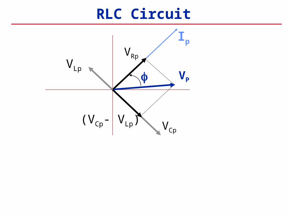
RLC Circuit
Ip
VRp
(VCp- VLp)
VP
VCp
VLp
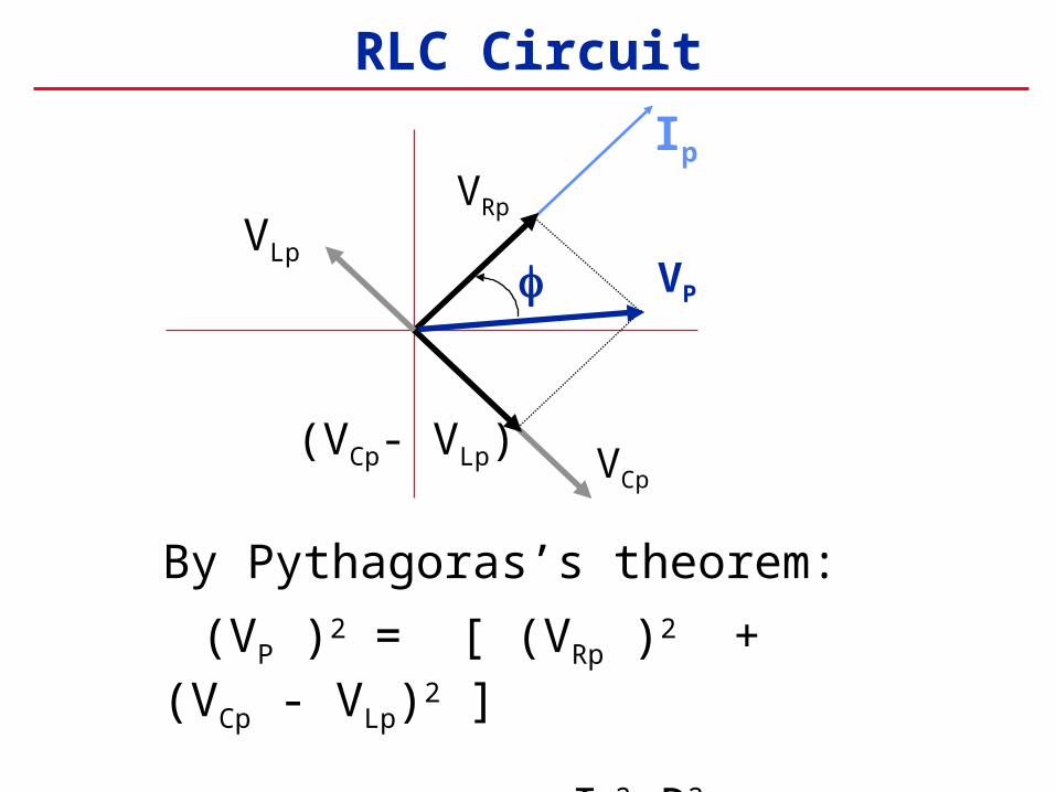
RLC Circuit
By Pythagoras’s theorem:
(VP )2 = [ (VRp )2 + (VCp - VLp)2 ]
= Ip2 R2 + (Ip XC - Ip XL)
2
Ip
VRp
(VCp- VLp)
VP
VCp
VLp

RLC Circuit
Solve for the current:
€
Ip =Vp
R2 + (Xc − XL )2=
Vp
Z
V
R
~ C
L
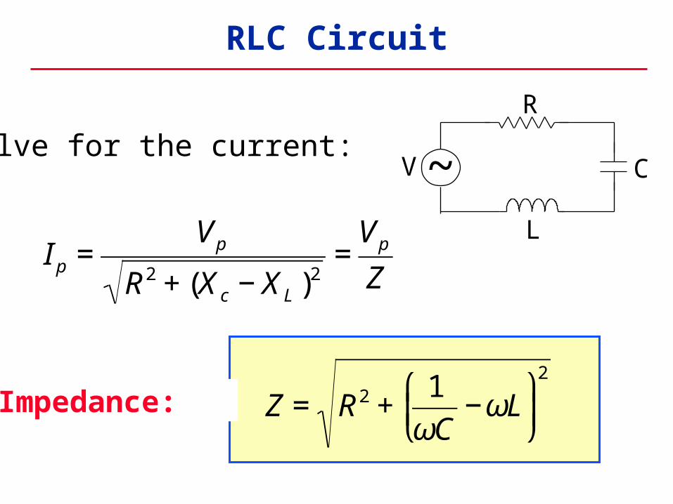
RLC Circuit
Solve for the current:
Impedance: €
Ip =Vp
R2 + (Xc − XL )2=
Vp
Z
€
Z = R2 +1
ωC−ωL
⎛
⎝ ⎜
⎞
⎠ ⎟2
V
R
~ C
L
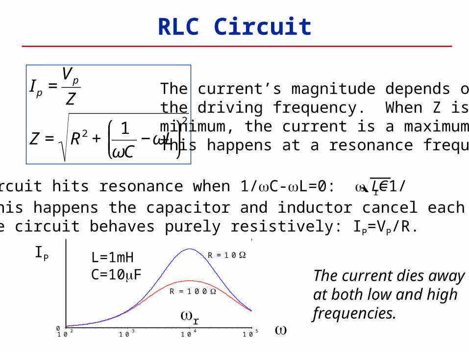
The circuit hits resonance when 1/C-L=0: r=1/When this happens the capacitor and inductor cancel each otherand the circuit behaves purely resistively: IP=VP/R.
RLC Circuit
€
Ip =Vp
Z
Z = R2 +1
ωC−ωL
⎛
⎝ ⎜
⎞
⎠ ⎟2
The current’s magnitude depends onthe driving frequency. When Z is aminimum, the current is a maximum.This happens at a resonance frequency:
LC
The current dies awayat both low and highfrequencies.
IP
01 0
21 0
31 0
41 0
5
R = 1 0 0
R = 1 0
r
L=1mHC=10F

Phase in an RLC Circuit
IpVRp
(VCp- VLp)
VP
VCp
VLp
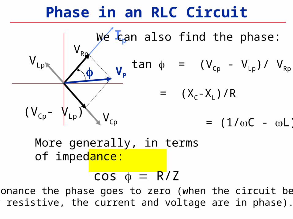
We can also find the phase:
tan = (VCp - VLp)/ VRp
= (XC-XL)/R = (1/C - L) / R
Phase in an RLC Circuit
At resonance the phase goes to zero (when the circuit becomespurely resistive, the current and voltage are in phase).
IpVRp
(VCp- VLp)
VP
VCp
VLp
We can also find the phase:
tan = (VCp - VLp)/ VRp
= (XC-XL)/R = (1/C - L) / R
More generally, in terms of impedance:
cos R/Z

The power dissipated in an AC circuit is P=IV. Since both I and V vary in time, so does the power: P is a function of time.
Power in an AC Circuit
Use V = VP sin (t) and I = IP sin (t+) :
P(t) = IpVpsin(t) sin (t+)
This wiggles in time, usually very fast. What we usually care about is the time average of this:
€
P =1
TP(t)dt
0
T
∫ (T=1/f )

Power in an AC Circuit
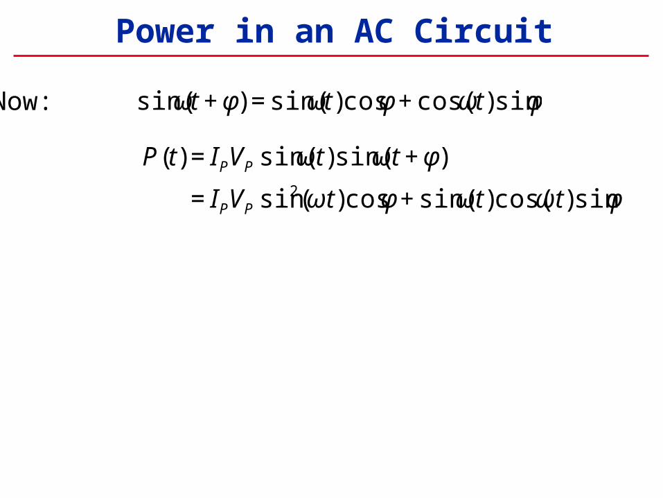
Now:
€
sin(ωt + φ) = sin(ωt)cosφ + cos(ωt)sinφ
Power in an AC Circuit
€
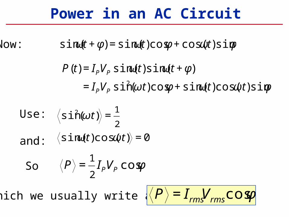
P(t) = IPVP sin(ωt)sin(ωt + φ)
= IPVP sin2(ωt)cosφ + sin(ωt)cos(ωt)sinφ
Now:
€
sin(ωt + φ) = sin(ωt)cosφ + cos(ωt)sinφ

Power in an AC Circuit
€
P(t) = IPVP sin(ωt)sin(ωt + φ)
= IPVP sin2(ωt)cosφ + sin(ωt)cos(ωt)sinφ
€
sin2(ωt) =1
2
sin(ωt)cos(ωt) = 0
Use:
and:
So
€
P =1
2IPVP cosφ
Now:
€
sin(ωt + φ) = sin(ωt)cosφ + cos(ωt)sinφ
Power in an AC Circuit
€
P(t) = IPVP sin(ωt)sin(ωt + φ)
= IPVP sin2(ωt)cosφ + sin(ωt)cos(ωt)sinφ
€
sin2(ωt) =1
2
sin(ωt)cos(ωt) = 0
Use:
and:
So
€
P =1
2IPVP cosφ
Now:
which we usually write as
€
P = IrmsVrms cosφ
€
sin(ωt + φ) = sin(ωt)cosφ + cos(ωt)sinφ
Power in an AC Circuit
€
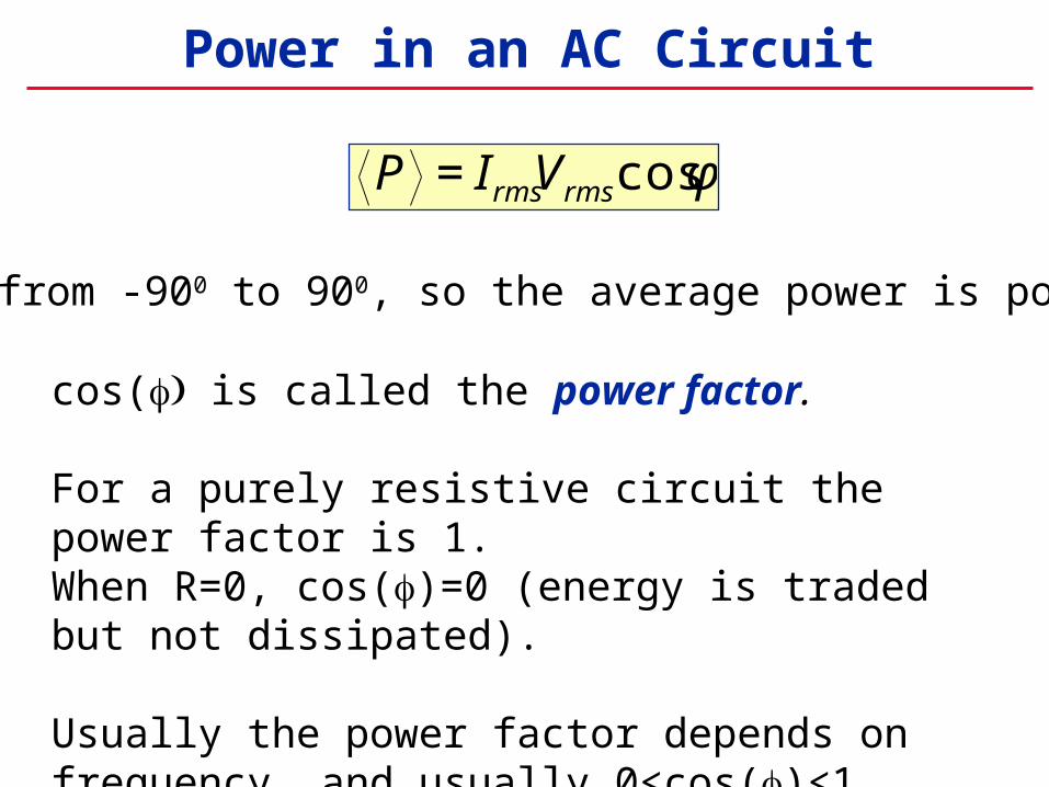
P = IrmsVrms cosφ
goes from -900 to 900, so the average power is positive)
cos( is called the power factor.
For a purely resistive circuit the power factor is 1.When R=0, cos()=0 (energy is traded but not dissipated).
Usually the power factor depends on frequency, and usually 0<cos()<1.

Power in a purely resistive circuit
V(t) = VP sin (t)
I(t) = IP sin (t)
P(t) = IV = IP VP sin 2(t) Note this oscillates
twice as fast.
V
t
I
t
P
= 0
(This is for a purely resistive circuit.)

Power in a purely reactive circuit
€
P = IrmsVrms cosφ
The opposite limit is a purely reactive circuit, with R=0.
IV P This happens with an
LC circuit.
Then 900
The time average of P is zero.
t

Transformers
Transformers use mutual inductance to change voltages:
Primary(applied voltage)
Secondary(produced voltage)
Ns turns
VpVs
Np turns Iron Core
€
Vs =Ns
N p
Vp
Faraday’s law on the left:If the flux per turn is then Vp=Np(d/dt).
Faraday’s law on the right:The flux per turn is also , so Vs=Ns(d/dt).

Transformers
Transformers use mutual inductance to change voltages:
Primary(applied voltage)
Secondary(produced voltage)
Ns turns
VpVs
Np turns Iron Core
€
Vs =Ns
N p
Vp
In the ideal case, no power is dissipated in the transformer itself.
Then IpVp=IsVs
€
Is =N p
Ns
Ip
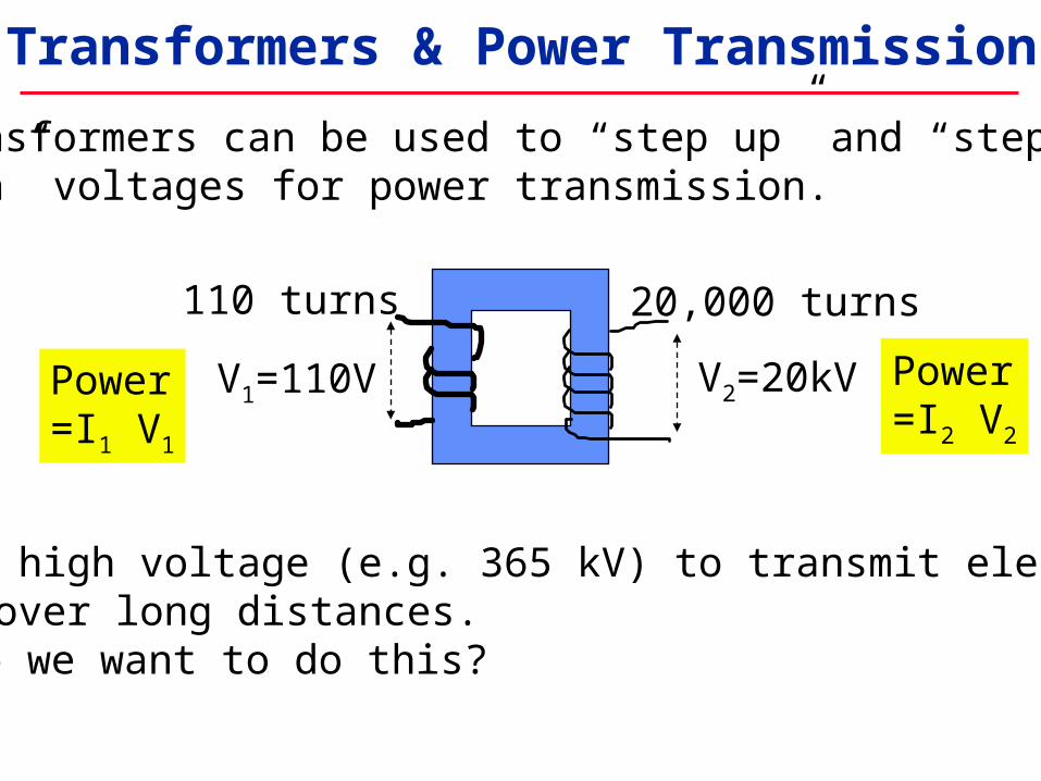
Transformers & Power Transmission
20,000 turns
V1=110V V2=20kV
110 turns
Transformers can be used to “step up” and “stepdown” voltages for power transmission.
Power=I1 V1
Power=I2 V2
We use high voltage (e.g. 365 kV) to transmit electricalpower over long distances.Why do we want to do this?

Transformers & Power Transmission
20,000 turns
V1=110V V2=20kV
110 turns
Transformers can be used to “step up” and “step down” voltages, for power transmission and other applications.
Power=I1 V1
Power=I2 V2
We use high voltage (e.g. 365 kV) to transmit electricalpower over long distances.
Why do we want to do this? P = I2R (P = power dissipation in the line - I is smaller at high voltages)