Embed Size (px)
Citation preview
7/26/2019 Allen Bradley TCP Ethernet
http://slidepdf.com/reader/full/allen-bradley-tcp-ethernet 1/102
Wonderware ®
ABTCP DAServer User’s Guide
Version 1.5
Last Revision: 3/21/07
Wonderware

7/26/2019 Allen Bradley TCP Ethernet
http://slidepdf.com/reader/full/allen-bradley-tcp-ethernet 2/102
All rights reserved. No part of this documentation shall be reproduced, storedin a retrieval system, or transmitted by any means, electronic, mechanical,
photocopying, recording, or otherwise, without the prior written permission of
Invensys Systems, Inc. No copyright or patent liability is assumed with respect
to the use of the information contained herein. Although every precaution has
been taken in the preparation of this documentation, the publisher and the
author assume no responsibility for errors or omissions. Neither is any liability
assumed for damages resulting from the use of the information contained
herein.
The information in this documentation is subject to change without notice and
does not represent a commitment on the part of Invensys Systems, Inc. The
software described in this documentation is furnished under a license or
nondisclosure agreement. This software may be used or copied only in
accordance with the terms of these agreements.
© 2002, 2004, 2007 Invensys Systems, Inc. All Rights Reserved.
Invensys Systems, Inc.
26561 Rancho Parkway South
Lake Forest, CA 92630 U.S.A.
(949) 727-3200
http://www.wonderware.com
Trademarks
All terms mentioned in this documentation that are known to be trademarks or
service marks have been appropriately capitalized. Invensys Systems, Inc.
cannot attest to the accuracy of this information. Use of a term in this
documentation should not be regarded as affecting the validity of any
trademark or service mark.
Alarm Logger, ActiveFactory, ArchestrA, Avantis, DBDump, DBLoad, DT
Analyst, FactoryFocus, FactoryOffice, FactorySuite, FactorySuite A2, InBatch,
InControl, IndustrialRAD, IndustrialSQL Server, InTouch, MaintenanceSuite,
MuniSuite, QI Analyst, SCADAlarm, SCADASuite, SuiteLink, SuiteVoyager,
WindowMaker, WindowViewer, Wonderware, and Wonderware Logger are
trademarks of Invensys plc, its subsidiaries and affiliates. All other brands may be trademarks of their respective owners.

7/26/2019 Allen Bradley TCP Ethernet
http://slidepdf.com/reader/full/allen-bradley-tcp-ethernet 3/102
Contents 3
ABTCP DAServer User’s Guide
Contents
Before You Begin ...............................................7
About This Book .................................................................................... 7
Introduction ........................................................9
Overview ................................................................................................ 9
Communications Protocols .................................................................. 10
Application Communications Protocols........................................... 10
Bus Communications Protocols.........................................................11
Accessing Items via the DAServer........................................................11
Features ................................................................................................ 13
Demo Mode.......................................................................................... 13
Configuration....................................................15
Getting Started Quickly with the DAServer ........................................ 15
Configuring the DAServer ................................................................... 18
ABTCP Hierarchy in the DAServer Manager.................................. 20
Configuring Device Group and Device Item Definitions .................... 27
Device Group Definitions................................................................. 28
Device Item Definitions.................................................................... 29
Scan-Based Message Handling ........................................................ 35
Unsolicited Message Handling......................................................... 35
Archiving Configuration Sets............................................................... 37
Hot Configuration ................................................................................ 37
Item Names .......................................................39
PLC-5 Item Naming............................................................................. 39
Output File Items .............................................................................. 41
Input File Items................................................................................. 41
Status File Items ............................................................................... 41
Binary File Items .............................................................................. 42
Timer File Items ............................................................................... 42
Counter File Items ............................................................................ 43
Control File Items............................................................................. 43Integer File Items.............................................................................. 44
Floating Point File Items .................................................................. 44
ASCII File Items............................................................................... 44
BCD File Items................................................................................. 45
ASCII String Section Items .............................................................. 45
Block Transfer Section Items ........................................................... 46
PID Section Items............................................................................. 46
SFC Status Section Items.................................................................. 47

7/26/2019 Allen Bradley TCP Ethernet
http://slidepdf.com/reader/full/allen-bradley-tcp-ethernet 4/102
4 Contents
ABTCP DAServer User’s Guide
PLC-5/250 (Pyramid Integrator) Item Naming.....................................47
Binary Section Items .........................................................................49
Counter Section Items .......................................................................49
Floating Point Section Items .............................................................50
Input Section Items............................................................................50
Long Integer Section Items ...............................................................51
MSG Section Items ...........................................................................51Integer Section Items.........................................................................52
Output Section Items .........................................................................52
PID Section Items..............................................................................53
Control Section Items........................................................................54
Status Section Items ..........................................................................54
String Section Items ..........................................................................55
Timer Section Items...........................................................................55
SLC-500 Item Naming..........................................................................55
Output File Items...............................................................................57
Input File Items .................................................................................57
Status File Items ................................................................................60
Binary File Items ...............................................................................60
Timer File Items ................................................................................61
Counter File Items .............................................................................61
Control File Items..............................................................................62
Integer File Items...............................................................................62
Floating Point File Items ...................................................................63
ASCII File Items ...............................................................................63
ASCII String Section Items ...............................................................63
DAServer Standard System Items.........................................................63
DAServer Global System Item..........................................................64
DAServer Device-Specific System Items .........................................65
DAServer Device-Group-Specific System Items..............................67Generic OPC Syntax .............................................................................69
Troubleshooting ...............................................71
Monitoring Connectivity Status with the PLC......................................71
Monitoring the Status of DAS Conversations.......................................72
Using DDEStatus and IOStatus in Excel...........................................72
Reading Values from the DAServer into Excel................................. 73
Writing Values to the DAServer from Excel.....................................73
Error Messages......................................................................................74
ABTCP DAServer Error Messages...................................................74PLC-5 Error Messages ......................................................................89
SLC 500 Error Messages...................................................................91
PLC-5/250 Error Messages ...............................................................91
PLC-5 and SLC 500 Error Messages ................................................92
PLC-5, SLC 500, and PLC-5/250 Error Messages............................92

7/26/2019 Allen Bradley TCP Ethernet
http://slidepdf.com/reader/full/allen-bradley-tcp-ethernet 5/102
Contents 5
ABTCP DAServer User’s Guide
Reference..........................................................95
DAServer Architecture......................................................................... 95
DAServers ........................................................................................ 95
Component Environments.................................................................... 97
Index..................................................................99

7/26/2019 Allen Bradley TCP Ethernet
http://slidepdf.com/reader/full/allen-bradley-tcp-ethernet 6/102
6 Contents
ABTCP DAServer User’s Guide

7/26/2019 Allen Bradley TCP Ethernet
http://slidepdf.com/reader/full/allen-bradley-tcp-ethernet 7/102
Before You Begin 7
ABTCP DAServer User’s Guide
Before You Begin
About This Book
This book describes the user interface and functions of the Wonderware®
ABTCP DAServer. The remainder of this book is organized in the following
fashion:
• Contents
• Introduction: contains overview information about the ABTCP
DAServer and the environment in which it works.
• Configuration: contains a detailed description of the user-interfaceelements of this DAServer as well as its functionality.
• Item Names: describes the item-naming conventions for targeted devices.
• Troubleshooting: provides information about error messages displayed
by this DAServer.
• Reference: describes DAServer architecture in general.
• Index
You can view this document on-line or you can print it, in part or whole, by
using the Adobe Acrobat Reader’s print facility. To view this document
properly, you must use version 4.0 of the Acrobat Reader.

7/26/2019 Allen Bradley TCP Ethernet
http://slidepdf.com/reader/full/allen-bradley-tcp-ethernet 8/102
8 Before You Begin
ABTCP DAServer User’s Guide

7/26/2019 Allen Bradley TCP Ethernet
http://slidepdf.com/reader/full/allen-bradley-tcp-ethernet 9/102
Introduction 9
ABTCP DAServer User’s Guide
C H A P T E R 1
Introduction
This chapter describes the Wonderware® ABTCP DAServer ™ (Data Access
Server), and the device and protocol environment in which it works. It includes
application- and bus-level communications protocols, item naming
conventions, and DAServer features.
Contents
• Overview
• Communications Protocols
• Application Communications Protocols
• Bus Communications Protocols
• Accessing Items via the DAServer
• Features
• Demo Mode
OverviewThe Wonderware ABTCP DAServer (referred to as the DAServer through the
remainder of this user’s guide) is a Microsoft® Windows® application program
that acts as a communications protocol server. Its user interface is a snap-in
Microsoft Management Console (MMC) program, which is part of the
ArchestrA System Management Console (SMC) suite of utilities.
This DAServer allows other Windows application programs access to data in
PLCs (also referred to as devices) attached to an Ethernet network or through a
Pyramid Integrator module. The DAServer requires a TCP/IP package that
supports the WinSock interface standard. It can access data directly via the
Ethernet in programmable controllers such as SLC-5/05, Ethernet PLC-5, or
PLC-5/250 using an Ethernet Interface Module (a Pyramid EI integratormodule).
While the DAServer is primarily intended for use with Wonderware InTouch®
Version 7.11 Patch 02 and later, it may be used by any Microsoft Windows
program capable of acting as a DDE, FastDDE, SuiteLink™, or OPC client.

7/26/2019 Allen Bradley TCP Ethernet
http://slidepdf.com/reader/full/allen-bradley-tcp-ethernet 10/102
10 Chapter 1
ABTCP DAServer User’s Guide
Communications Protocols
The ABTCP DAServer communicates with clients and PLCs using different
communications protocols. The DAServer uses application protocols such as
OPC, DDE, and SuiteLink to communicate with clients, and TCP/IP bus
protocol to communicate with PLCs.
For more information about the DAServer architecture, see the Reference
section.
Application Communications Protocols
OPC (OLE for Process Control) is a non-proprietary set of standard interfaces
based upon Microsoft’s OLE/COM technology. This standard makes possible
interoperability between automation/control applications, field systems/
devices and business/office applications. Avoiding the traditional requirement
of software/application developers to write custom drivers to exchange data
with field devices, OPC defines a common, high performance interface that
permits this work to be done once, and then easily reused by HMI, SCADA,
control and custom applications. Over the network, OPC uses DCOM(Distributed COM) for remote communications.
SuiteLink uses a TCP/IP-based protocol and is designed specifically to meet
industrial needs such as data integrity, high throughput, and easier diagnostics.
This TCP/IP standard is supported on Windows NT and Windows NT-
technology-based operating systems (for example, Windows 2000, Windows
XP, and Windows 2003).
SuiteLink is not a replacement for DDE, FastDDE, or NetDDE. The protocol
used between a client and a server depends on your network connections and
configurations. SuiteLink provides the following features:
• Value Time Quality (VTQ) places a timestamp and quality indicator on all
data values delivered to VTQ-aware clients.
• Extensive diagnostics of the data throughput, server loading, computer
resource consumption, and network transport are made accessible through
the operating system’s performance monitor. This feature is critical for the
operation and maintenance of distributed industrial networks.
• Consistent high data volumes can be maintained between applications
regardless if the applications are on a single node or distributed over a
large node count.
• The network transport protocol is TCP/IP using Microsoft’s standard
WinSock interface.
FastDDE provides a means of packing many proprietary Wonderware
Dynamic Data Exchange messages into a single Microsoft DDE message. This packing improves efficiency and performance by reducing the total number of
DDE transactions required between a client and a server. Although
Wonderware's FastDDE has extended the usefulness of DDE for our industry,
this extension is being pushed to its performance constraints in distributed
environments.

7/26/2019 Allen Bradley TCP Ethernet
http://slidepdf.com/reader/full/allen-bradley-tcp-ethernet 11/102
Introduction 11
ABTCP DAServer User’s Guide
DDE is a communications protocol developed by Microsoft to allow
applications in the Windows environment to send/receive data and instructions
to/from each other. It implements a client/server relationship between two
concurrently running applications. The server application provides the data and
accepts requests from any other application interested in its data. Requesting
applications are called clients. Some applications such as InTouch and
Microsoft Excel can simultaneously be both a client and a server.
NetDDE is a communications protocol that extends the standard DDE
functionality to include communications over local area networks and through
serial ports. Network extensions are available to allow DDE links between
applications running on different computers connected via networks or
modems. For example, NetDDE supports DDE between applications running
on IBM-compatible computers connected via LAN or modem and DDE-aware
applications running on non-computer-based platforms under operating
environments such as VMS and UNIX.
Bus Communications Protocols
This DAServer uses TCP/IP (Transmission Control Protocol/Internet Protocol) bus-level protocol.
TCP is the lower-level transport and data-link vehicle for data delivery over an
IP network. It provides reliable connection-oriented full-duplex data stream
transport. IP is the basic protocol for the Internet which uses an IP address
scheme to send data in packets across networks.
Accessing Items via the DAServer
The method for accessing items through the DAServer depends on the
communications protocol being used.
In the case of OPC communications, the protocol addresses an element of data
in a conversation with six characteristics: node name, program name, group
name, device group, link name, and item name.
• The node name (required for remote access) and device group are
optional.
• A fully qualified OPC Item name (ItemID) is composed of the link name
and item name.
• All other characteristics are specified through separate DAServer means.
To access an OPC item, the OPC client needs to connect to the DAServer
(either in-process or out-of-process) and create an OPC group defining the
data-acquisition properties for the collection of items to be added. OPC groupscan be either public or private. Public OPC groups are shared across multiple
clients, whereas private OPC groups are local to a single client. Optionally a
device group, which indicates the access path to the items for read/write, can
be specified from the DAServer.
The following briefly describes each characteristic of the OPC protocol:
• node name: Computer (host) name identifying a specific node on the
network (for Remote Access ONLY).

7/26/2019 Allen Bradley TCP Ethernet
http://slidepdf.com/reader/full/allen-bradley-tcp-ethernet 12/102
12 Chapter 1
ABTCP DAServer User’s Guide
• program name: The registered OPC server name uniquely identifying a
specific server (ProgID). For this DAServer, the program name is
ArchestrA.DASABTCP.1.
• group name: The OPC group created from the client for organizing a
collection of items logically with the same data acquisition properties
between the client and the server, such as update rate.
• device group: Meaningful names configured in the DAServer under a
specific controller for the common custom attributes between the
DAServer and the device, such as update interval. If not specified from the
client, the default device group using the global configuration attribute
values from the DAServer is assumed. Functionally a device group is
equivalent to an access path (optional).
• link name: The set of hierarchy node names, representing the specific
devices on a communications path link from the hierarchy root to a
specific controller as configured for this DAServer under the DAServer
Manager, separated by delimiters.
• item name: A specific data element, the leaf of the hierarchy tree of this
DAServer, within the specified group. For example, when using thisDAServer, an item can be a relay, timer, counter, register, and so on, in the
controller.
In the case of DDE/SuiteLink communications, the protocol addresses an
element of data in a conversation that uses a four-part naming convention that
includes the node name, application name, topic name, and item name. The
fully qualified DDE/SuiteLink naming convention includes all four parts,
although the node name part (required for remote access only) is optional. The
following briefly describes each portion of this naming convention:
• node name: Computer (host) name identifying a specific node on the
network (for Remote Access ONLY).
• application name: The name of the Windows program (this DAServer)that will be accessing the data element. In the case of data coming from or
going to Allen-Bradley devices via the DDE/SuiteLink PlugIn of this
DAServer, the application name portion of the address is DASABTCP.
• topic name: Meaningful names are configured in the DAServer to identify
specific devices. These names are then used as the topic names in all
conversations with that device. For example, ABPLC. Topic name maps
to a device group defined in the DAServer.
Note You can define multiple device-group (topic) names for the same
device (PLC) to poll different points at different rates.
• item name: A specific data element within the specified topic. For
example, when using this DAServer, an item can be a relay, timer, counter,
register, and so on, in the PLC.
Note The term "point" is used interchangeably with the term "item" in
this user's guide.
For more information on item/point names, see the Item Names section of this
user's guide.

7/26/2019 Allen Bradley TCP Ethernet
http://slidepdf.com/reader/full/allen-bradley-tcp-ethernet 13/102
Introduction 13
ABTCP DAServer User’s Guide
Features
The ABTCP DAServer provides the following features:
• The ability to communicate over multiple application-level protocols at
the same time.
• The ability to add new application-level protocols on the fly.
• The ability to be configured remotely.
• New, robust diagnostics abilities.
• Additional server-specific diagnostics.
• XML storage.
For example, the storage of the .aacfg file that has the details of all the
device groups and device items that can be stored in XML.
• Full existing item-name space.
• Log of errors, warnings, traces, and messages, individually adjustable for
reading and writing.
• OPC browsing.
For more in-depth information on the DAServer architecture, see the
Reference section.
Demo Mode
You can install a fully functioning version of this DAServer for demonstration
purposes without a license. Demo Mode allows you to test the functionality of
the DAServer for 120 minutes. After that time, you must install a license to
continue using the DAServer.
When you first start this DAServer, it checks for a license. If the DAServercannot find a valid license installed on the local computer, it logs a warning
message indicating a valid license cannot be retrieved, and enters Demo mode.
Thereafter, the DAServer repeats its request for the license every 30 seconds. If
no license is found, the DAServer again logs a warning message on the issue.
This process is repeated for 120 minutes, after which the server stops updating
read/write on all device items (read from cache is allowed, but all non-system
data would receive Bad quality status). The DAServer continues to request for
a license. Clients continue to function normally (for instance, you can still add
or remove an item, but its quality is set to Bad until a license is obtained).
Note Use the $SYS$Licensed system item, a read-only Boolean item, to
check the status of your license: True for Licensed or during Demo mode, and
False for Not Licensed.
If you subsequently add a license to the License Manager, the DAServer logs a
message acknowledging the license, switches out of Demo mode, and runs
normally.

7/26/2019 Allen Bradley TCP Ethernet
http://slidepdf.com/reader/full/allen-bradley-tcp-ethernet 14/102
14 Chapter 1
ABTCP DAServer User’s Guide
Note Once a DAServer obtains a valid license, it no longer checks for a
license. Thus, if your license expires, your DAServer would cease to function
but this condition would not be logged until the next restart of the DAServer.

7/26/2019 Allen Bradley TCP Ethernet
http://slidepdf.com/reader/full/allen-bradley-tcp-ethernet 15/102
Configuration 15
ABTCP DAServer User’s Guide
C H A P T E R 2
Configuration
Once the Wonderware ABTCP DAServer has been installed, a small amount of
configuration is required. This configuration is performed using the DAServer
Manager hosted in the System Management Console (SMC) after it is started
through the Programs menu of the Windows Start button.
After the SMC, in which the unconfigured DAServer node is located, has been
started, the device hierarchy, simulating the physical hardware layout, must
first be built to establish communications to each of the controllers. Once the
ABTCP hierarchy has been built, the respective devices for communications
can be configured. Finally, the desired Device Groups for each controller may
be created.
Contents
• Getting Started Quickly with the DAServer
• Configuring the DAServer
• Configuring Device Group and Device Item Definitions
• Archiving Configuration Sets
• Hot Configuration
Getting Started Quickly with the DAServer
This section briefly describes the procedures required to install and prepare the
ABTCP DAServer for use. Detailed descriptions of each step can be found in
later sections of this documentation. This section is intended for people who
are familiar with DAServers.
Note If you are not familiar with DAServer functionality, please proceed to
the more detailed procedures following this section.
The following procedures assume that you have:
• Installed the Ethernet adapter and TCP/IP software on your computer,
following the instructions provided by the manufacturer;
• Defined Host Names for all PLCs on the network by modifying the hosts
file, if you plan to configure your DAServer using Host Names rather than
IP addresses directly.

7/26/2019 Allen Bradley TCP Ethernet
http://slidepdf.com/reader/full/allen-bradley-tcp-ethernet 16/102
16 Chapter 2
ABTCP DAServer User’s Guide
Note Refer to your Microsoft documentation for information about the
location of the hosts file and the format of its contents.
To prepare the ABTCP DAServer
1. Install the Wonderware ABTCP DAServer on Windows by running the
Setup.exe program.
Note DAServer installation instructions are included in a separate Help file
(.chm extension).
• Accept all the default settings during installation.
Note Since there are no default values for security settings, you must take
note of the User Name and password selected during install.
2. Start the Wonderware DAServer Manager by selecting the Programs
menu from the Start button on the taskbar.
3. Navigate to the Wonderware folder that contains the SystemManagement Console, then click System Management Console.
4. From the System Management Console, find the ABTCP DAServer in
the DAServer Manager tree, the location in which it is installed.
• Under the Local Node, the DAServer name is
ArchestrA.DASABTCP.1.
• See the DAServer Manager Online Help for general information
about working in this snap-in environment.
5. The new ABTCP DAServer must now be configured.
• Before proceeding, determine the hierarchical structure of the
network/PLC environment to which you plan to connect.6. Right-click the Configuration branch of the hierarchy, and select Add
PORT_TCPIP Object from the shortcut menu:
• The DAServer allows only one PORT_TCPIP object in the hierarchy.
• In this step, in addition to Steps 7 and 8, the hierarchy entry is added
in "edit mode," providing a convenient place for you to appropriately
describe components of your specific hardware environment.
• If you do not rename the object at this time, a numeric sequencing
system is applied.
• Any hierarchy entry can be renamed at a later time.
7. Right-click the object you created in the tree, and select the appropriateobject from the three choices provided:
Add PLC5_TCPIP Object
Add SLC500_TCPIP Object
Add PYRAMID_EI Object
• You can add up to 1024 of each of these objects to the hierarchy.
• If you add a PYRAMID_EI object, you must configure the
Pyramid_EI hierarchy further; go to Step 8.

7/26/2019 Allen Bradley TCP Ethernet
http://slidepdf.com/reader/full/allen-bradley-tcp-ethernet 17/102
Configuration 17
ABTCP DAServer User’s Guide
• PLC5_TCPIP and SCL500_TCPIP objects represent the logical end
points for the hierarchy being configured, and they have no
configurable child objects. Go to Step 9.
8. Right-click the new PYRAMID_EI object, and select Add
PYRAMID_PLC5250 Object.
• The PYRAMID_PLC5250 objects are limited to four hierarchy
entries.
9. Configure the respective device objects, created in the preceding steps,
with the appropriate parameter values, if applicable.
• Optionally, the desired device groups can be created under the Device
Groups tabbed page with each of the PLC objects.
• Desired device items can also be optionally created under the Device
Items tabbed page with each of the PLC objects.
Note When any configuration view is in an open state and you open the same
server the second time, the DAServer locks the second instance of this same-
server access for any update or configuration activities. Access to this second
opening instance will resume after the first one has been closed.
The DAServer is now ready for use. In order to use the DAServer, it needs to
be activated.
• If you are using an OPC Client, the DAServer will auto-start.
• If you are using DDE/SuiteLink, you must start the DAServer either
as a manual or automatic service.
• The DAServer can be activated by right-clicking on
ArchestrA.DASABTCP.1 and selecting Activate Server from the
shortcut menu.
Note To run the ABTCP DAServer as a service, use the shortcut menu on theDAServer name and select Configure As Service. You can configure it as an
auto service or manual service. For more information about configuring the
DAServer as a service, see the Activation/Deactivation/Service Component of
the DAServer Manager documentation.

7/26/2019 Allen Bradley TCP Ethernet
http://slidepdf.com/reader/full/allen-bradley-tcp-ethernet 18/102
18 Chapter 2
ABTCP DAServer User’s Guide
Configuring the DAServer
Note This DAServer is hosted by the DAServer Manager, a Microsoft
Management Console (MMC) snap-in, which is part of the ArchestrA System
Management Console (SMC) suite of utilities. Many high-level functions and
user-interface elements of the DAServer Manager are universal to all
DAServers, and only the documentation for the DAServer Manager contains
descriptions of those universal functions/UI elements. Therefore, reading the
documentation for both the MMC and the DAServer Manager is critical to
understanding this user’s guide. To read the documentation about the MMC
and DAServer Manager, click the Help topics on the SMC Help menu. Both
the MMC and DAServer Manager Help is displayed. An Adobe Acrobat
version of the DAServer Manager documentation (DAServerManager.pdf) is
provided.
Note The shortcut menu items described in this document typically represent
only a subset of any actual shortcut menu. Most items in each shortcut menu
are standard Windows commands. See the MMC’s Help for more information
about those commands.
Before the DAServer can be configured, the Ethernet adapter and TCP/IP
software must be installed on your computer; and, if you plan to configure your
DAServer using Host Names rather than the IP addresses directly, the Host
Names for all PLCs on the Ethernet need to be defined by modifying the hosts
file.
To install the Ethernet adapter
1. Install the Ethernet adapter and TCP/IP software following the
instructions provided by the manufacturer.
2. The DAServer configuration accepts either Host Names or IP addresses
directly.
• You can configure Host Names directly in the DAServer Manager.
• Optionally, if Host Names will be used, then the Host Names for all
PLCs on the network need to be defined by modifying the hosts file.
• Refer to the documentation provided by Microsoft for information
about the location of the hosts file and the format of its contents.
3. Restart the computer.
To prepare the ABTCP DAServer
1. Install the ABTCP DAServer from Windows by running the Setup.exe
program.
Note DAServer installation instructions are included in a separate Help file
(.chm extension).
2. Accept all the default settings during installation.

7/26/2019 Allen Bradley TCP Ethernet
http://slidepdf.com/reader/full/allen-bradley-tcp-ethernet 19/102
Configuration 19
ABTCP DAServer User’s Guide
Note Since there are no default values for security settings, you must take
note of the User Name and password selected during install.
3. After the ABTCP DAServer has been installed, a small amount of
configuration is required. Start the System Manager Console by clicking
the Start button on the Windows taskbar, and pointing to Programs.
4. Point to the Wonderware folder that contains the System Management
Console, then click System Management Console.
5. From the System Management Console tree, click on DAServer
Manager.
6. Click on Local Domain, then Local Node.
• Under the Local Node, the DAServer name is
ArchestrA.DASABTCP.1.
Note See the DAServer Manager Online Help for general information about
working in this snap-in environment.
7. Before the DAServer is started, the device hierarchy must first be built to
establish communications to each of the controllers.
Important! For step-by-step procedures on how to build the device hierarchy,
please see the following section, "ABTCP Hierarchy in the DAServer
Manager ."
7/26/2019 Allen Bradley TCP Ethernet
http://slidepdf.com/reader/full/allen-bradley-tcp-ethernet 20/102
20 Chapter 2
ABTCP DAServer User’s Guide
Note Selecting the Configuration object of the hierarchy tree displays the
Global Parameters interface for this DAServer. The default Poke Mode
settings for the DAServer is Optimization mode. Configure all other global
parameters as required for this DAServer. For more information about the
Global Parameters dialog box, including descriptions of the different Poke
Modes, see the DAServer Manager documentation. You can access that
documentation by clicking the DAServer Manager icon and selecting theHelp topics on the Help menu, and then navigating through the DAServer
Manager book.
Important! Any Global Parameters that appear dimmed are not supported.
8. When the ABTCP hierarchy build has been completed, you can start
configuring the respective devices for communications.
• Optionally, the desired device groups can be created under the Device
Groups tabbed page with each of the PLC objects.
• Desired device items can also be optionally created under the Device
Items tabbed page with each of the PLC objects.
Note The hierarchy entry is added in the "edit mode," providing a convenient
place for you to appropriately describe components of your specific hardware
environment. Both hierarchy node name and device group name are
numerically sequenced by default. They can be renamed at any time.
The DAServer will be ready to use after it is activated.
• If you are using an OPC Client, the DAServer will auto-start.
• If you are using DDE/SuiteLink, you must start the DAServer either as a
manual or automatic service.
• The DAServer can be activated by right-clicking onArchestrA.DASABTCP.1 and selecting Activate Server from the
shortcut menu.
Note To run the ABTCP DAServer as a service, right-click on the DAServer
name and select Configure As Service from the shortcut menu. You can
configure it as an auto service or manual service. For more information about
configuring the DAServer as a service, see the Activation/Deactivation/Service
Component of the DAServer Manager documentation.
Note When any configuration view is in an open state and you open the same
server the second time, the DAServer locks the second instance of this same-
server access for any update or configuration activities. Access to this second
opening instance will resume after the first one has been closed.
ABTCP Hierarchy in the DAServer Manager
Before attempting to configure your DAServer, you should determine the
hierarchical structure of your network/PLC environment.
7/26/2019 Allen Bradley TCP Ethernet
http://slidepdf.com/reader/full/allen-bradley-tcp-ethernet 21/102
Configuration 21
ABTCP DAServer User’s Guide
TCPIP Object
The server-specific configuration portion of the ABTCP DAServer hierarchy
tree under the DAServer Manager starts at the TCPIP object.
• It is a logical representation of the Ethernet port for TCPIP
communications in a computer.
• Only one TCPIP object is allowed per ABTCP DAServer, and when you
first install the DAServer, it is already provided for you.
• Rename this object as appropriate.
Important! If you subsequently clear your configuration hierarchy, you must
create this TCPIP port object by right-clicking on the Configuration object
and selecting Add PORT_TCPIP Object from the shortcut menu. An object
called New_PORT_TCPIP_000 is created. Rename as appropriate. From this
point, all of the following instructions apply.
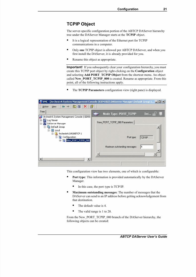
• The TCPIP Parameters configuration view (right pane) is displayed.
This configuration view has two elements, one of which is configurable:
• Port type: This information is provided automatically by the DAServer
Manager.
• In this case, the port type is TCP/IP.
•Maximum outstanding messages: The number of messages that the
DAServer can send to an IP address before getting acknowledgement from
that destination.
• The default value is 4.
• The valid range is 1 to 20.
From the New_PORT_TCPIP_000 branch of the DAServer hierarchy, the
following objects can be created:

7/26/2019 Allen Bradley TCP Ethernet
http://slidepdf.com/reader/full/allen-bradley-tcp-ethernet 22/102
22 Chapter 2
ABTCP DAServer User’s Guide
• PLC5_TCPIP Object (representing PLC5/20E through PLC5/80E PLCs)
• SLC500_TCPIP Object (representing SLC5/05 PLC)
• PYRAMID_EI Object (representing your Ethernet Interface 5820-EI
module)
PLC5_TCPIP Object
The PLC5_TCPIP object is created from the New_PORT_TCPIP_000 branch
of the DAServer hierarchy.
To add the PLC5_TCPIP object to your ABTCP hierarchy
1. Right-click on the New_PORT_TCPIP_000 branch.
2. Select Add PLC5_TCPIP Object from the shortcut menu.
3. Rename as appropriate.
Note You can add up to 1024 of each type object to the hierarchy.
• The PLC5_TCPIP object represents the logical endpoint to the
hardware hierarchy.
• The New_PLC5_TCPIP_000 Parameters configuration view is
displayed.
This configuration view has six configurable elements:
• Host Name: Either the host name or IP address of the destination.

7/26/2019 Allen Bradley TCP Ethernet
http://slidepdf.com/reader/full/allen-bradley-tcp-ethernet 23/102
Configuration 23
ABTCP DAServer User’s Guide
• The host name is defined in the system host file (usually it is
\WINNT\system32\drivers\etc\hosts).
Note The Host Name defaults to the LocalHost. If the LocalHost is
selected and deleted, resulting in a blank Host Name field, and you apply
the changes, this will result in an error message.
• Data block size: The number of date bytes that can be sent in a message
for this hierarchy.
• For reading blocks:
The default value is 2000 bytes.
The valid range is 2 to 2000.
• For writing blocks:
The maximum writing block is 220 bytes, and not configurable.
• Connection timeout: The time allowed to establish a socket connection to
a target device.
• The default value is 2000 milliseconds.
• The valid range is 1000 to 20000 milliseconds.
• Reply timeout: The time (in Seconds) the DAServer will wait for the
acknowledgement after it sends out a message. The message will be resent
when time-out occurred.
• The default value is 15.
• The valid range is 1 to 300 seconds.
• Supports PID and string files: Set this flag if using a 1785 PLC-5 that
supports PID, ASCII String, Block Transfer, and SFC Status Files.
• Supports unsolicited ‘CLIENT’ messaging: Set this flag to true to
enable the DAServer to receive unsolicited "CLIENT" data updates from
the selected PLC.
• The DAServer is enabled automatically to accept normal, "Peer-to-
Peer" unsolicited data updates without this flag set to true.
• The reason to turn on this flag is if the MSG instructions programmed
inside the PLC/Host is configured with "CLIENT" as the target
station, rather than a specific IP address on the network.
SLC500_TCPIP Object
The SLC500_TCPIP object is created from the New_PORT_TCPIP_000
branch of the DAServer hierarchy.
To add the SLC500_TCPIP object to your ABTCP hierarchy
1. Right-click on the New_PORT_TCPIP_000 branch.
2. Select Add SLC500_TCPIP Object from the shortcut menu.
3. Rename as appropriate.

7/26/2019 Allen Bradley TCP Ethernet
http://slidepdf.com/reader/full/allen-bradley-tcp-ethernet 24/102
24 Chapter 2
ABTCP DAServer User’s Guide
Note You can add up to 1024 of each type object to the hierarchy.
• The SLC500_TCPIP object represents the logical endpoint to the
hardware hierarchy.
• The New_SLC500_TCPIP_000 Parameters configuration view is
displayed.
This configuration view configures the SLC-500 processor on an Ethernet
direct connection. It contains four configurable elements:
• Host name: Either the host name or IP address of the destination.
• The host name is defined in the system host file (usually it is
\WINNT\system32\drivers\etc\hosts).
Note The Host Name defaults to the LocalHost. If the LocalHost is selected
and deleted, resulting in a blank Host Name field, and the Apply button is
clicked on, an error message will appear.
• Data block size: The number of date bytes that can be sent in a message
for this hierarchy.
• For reading blocks:
The default value is 510 bytes.The valid range is 2 to 510.
• For writing blocks:
The maximum writing block is 220 bytes, and not configurable.
• Connection timeout: The time allowed to establish a socket connection to
a target device.
• The default value is 2000 milliseconds.

7/26/2019 Allen Bradley TCP Ethernet
http://slidepdf.com/reader/full/allen-bradley-tcp-ethernet 25/102
Configuration 25
ABTCP DAServer User’s Guide
• The valid range is 1000 to 20000 milliseconds.
• Reply timeout: The time (in Seconds) the DAServer will wait for the
acknowledgement after it sends out a message.
• The message will be resent when time-out occurred.
• The default value is 15.
• Valid range is 1 to 300 seconds.
PYRAMID_EI Object
The PYRAMID_EI object is created from the New_PORT_TCPIP_000 branch
of the DAServer hierarchy.
To add the PYRAMID_EI object to your ABTCP hierarchy
1. Right-click on the New_PORT_TCPIP_000 branch.
2. Select Add PYRAMID_EI Object from the shortcut menu.
3. Rename as appropriate.
Note You can add up to 1024 of each type object to the hierarchy.
• The New_ Pyramid_EI_000 Parameters configuration view is
displayed.
This configuration view has three parameters. One parameter, the Ethernet
Interface module type 5820-EI, is not configurable. The other two configurable
parameters are as follows:
• Host name: Either the host name or IP address of the destination.
• The host name is defined in the system host file (usually it is
\WINNT\system32\drivers\etc\hosts).

7/26/2019 Allen Bradley TCP Ethernet
http://slidepdf.com/reader/full/allen-bradley-tcp-ethernet 26/102
26 Chapter 2
ABTCP DAServer User’s Guide
Note The Host Name defaults to the LocalHost. If the LocalHost is
selected and deleted, resulting in a blank Host Name field, and you apply
the changes, this will result in an error message.
• Connection timeout: Time allowed to establish a socket connection to a
target device.
• The default value is 2000 milliseconds.
• Valid range is 1000 to 20000 milliseconds.
PYRAMID_PLC5250 Object
From the New_PYRAMID_EI_000 branch of the DAServer hierarchy, the
following object can be created:
• PYRAMID_PLC5250 Object
To add the PYRAMID_PLC5250 object to your ABTCP hierarchy
1. Right-click on your New_PYRAMID_EI_000 branch.
2. Select Add PYRAMID_PLC5250 Object from the shortcut menu.
3. Rename as appropriate.
Note You can add up to four PYRAMID_PLC5250 objects to the
hierarchy.
• The PYRAMID_PLC5250 object represents the logical endpoint to
the hardware hierarchy.
• The New_PYRAMID_PLC5250_000 Parameters configuration
view is displayed.
This configuration view has three configurable elements:

7/26/2019 Allen Bradley TCP Ethernet
http://slidepdf.com/reader/full/allen-bradley-tcp-ethernet 27/102
Configuration 27
ABTCP DAServer User’s Guide
• Data block size: The number of date bytes that can be sent in a message
for this hierarchy.
• For reading blocks:
The default value is 2000 bytes.
The valid range is 2 to 2000.
• For writing blocks:
The maximum writing block is 220 bytes, and not configurable.
• Reply timeout: The time (in Seconds) the DAServer will wait for the
acknowledgement after it sends out a message. The message will be resent
when time-out occurred.
• The default value is 15.
• Valid range is 1 to 300 seconds.
• Supports unsolicited ‘CLIENT’ messaging: Set this flag to true to
enable the DAServer to receive unsolicited "CLIENT" data updates from
the selected PLC.
• The DAServer is enabled automatically to accept normal, "Peer-to-
Peer" unsolicited data updates without this flag set to true.
• The reason to turn on this flag is if the MSG instructions programmed
inside the PLC/Host is configured with "CLIENT" as the target
station, rather than a specific IP address on the network.
You have reached the logical endpoint of the ABTCP hierarchy tree.
Note The default name created from adding a hierarchy object is in the format
of New_ObjectName_###, where ObjectName is the name of the object type
and ### is a numeric value starting from "000" enumerated sequentially per
hierarchy object. The link name for the OPC items is constructed by
assembling the respective object names of the nodes along the hierarchy tree in
the logical order starting from this DAServer’s PORT_TCPIP root down to the
leaf. Therefore, the link name is always unique for the DAServer.
Note In order to use the DAServer, you must activate it. See the DAServer
Manager documentation for information about how to activate and deactivate
the DAServer.
Configuring Device Group and Device ItemDefinitions
The Device Groups tab in the DAServer Manager user interface is used tocreate new, modify, or delete device group definitions for an object. For
DDE/SuiteLink communications, one or more device group definitions must
exist for each PLC that the DAServer will communicate with.

7/26/2019 Allen Bradley TCP Ethernet
http://slidepdf.com/reader/full/allen-bradley-tcp-ethernet 28/102
28 Chapter 2
ABTCP DAServer User’s Guide
Important! For DDE/SuiteLink, it is strongly recommended that each device
group (topic) definition contain a unique name for the PLC associated with it.
The OPC, however, has the flexibility to use any names, including duplicate
names, for the device group definitions.
Device Group DefinitionsThe Device Groups dialog box, which is displayed by clicking the Device
Groups tab in the New_<Name>PLC_000 Parameters configuration view, is
used to perform the following activities:
• Adding, defining, and deleting device groups.
Note When you add a new device group, enter a unique name.
• Configuring default update intervals.
• Editing update intervals for the objects.
Note When you select another part of the DAServer tree hierarchy, you are
prompted to save the modifications to the configuration set.
To create or add device groups
1. Right-click in the Device Groups dialog box.
2. Select the Add command from the shortcut menu.
• When you add a new device group, enter a unique name (up to 32
characters long).
To make edits on device groups
Make edits on a device group’s name or update interval for an object as
follows:

7/26/2019 Allen Bradley TCP Ethernet
http://slidepdf.com/reader/full/allen-bradley-tcp-ethernet 29/102
Configuration 29
ABTCP DAServer User’s Guide
• In the Name column, double-click on the device group’s name to be edited
and make the edit.
• Double-click on the device group’s value to be edited in the Update
Interval column, and make the edit.
To delete device groups
Deleting a device group from the list can be performed as follows:
1. Right-click on the device group to be deleted.
2. Select the Delete command from the shortcut menu.
Note When you select another part of the ABTCP DAServer tree hierarchy,
you are prompted to save the modifications to the configuration set.
To configure default update intervals
1. To configure a default update interval for the object, right-click in the
Device Groups dialog box.
2. Select Config Default Update Interval from the shortcut menu.
To edit update intervals
• To edit the update interval for an object, double-click its value in the
Update Interval column and make the edit.
• Update Interval is the frequency (in milliseconds) that the DAServer
acquires data from the topics associated with that device group.
• Different topics can be polled at different rates in a PLC by defining
multiple device-group names for the same PLC and setting a different
Update Interval for each device group.
Note When you select another part of the ABTCP DAServer tree hierarchy,you are prompted to save the modifications to the configuration set.
Each configuration view associated with nodes/objects in the DAServer
hierarchy tree has a common feature, the Save button.
1. When you modify any parameters in the Device Groups dialog box, click
Save to save and implement the new modifications.
• If you do not click Save, the configuration is reset to its original
condition (since the last save).
2. After all modifications, you must save when prompted for the new data to
be saved to the configuration set.
Device Item Definitions
The Device Items tab in the New_<Name>PLC_000 Parameters
configuration view is used to define aliases to actual PLC items. The Device
Items dialog box is the place where the following activities are performed:
• Creating new device item definitions for PLC items.

7/26/2019 Allen Bradley TCP Ethernet
http://slidepdf.com/reader/full/allen-bradley-tcp-ethernet 30/102
30 Chapter 2
ABTCP DAServer User’s Guide
• Modifying the existing device items.
• Deleting device items.
• Archiving the created list of device items to a .csv file, a file with values
separated by commas.
• Bringing a .csv file into the Device Items tab.
Each device item definition should contain a unique name for the PLC
associated with it.
The Device Items dialog box has the following two columns:
• Name: This column defines the alias names to actual PLC items.
• Item Reference: The actual PLC item names, linked to the created aliases,
are defined in this column.
For example:.
Note When you create or add a new device item, a unique name needs to be
entered for it.
Once the Device Items feature is utilized to configure item names, it provides
the DAServer with the capability to perform OPC Item browsing. When the
DAServer is running and an OPC client requests item information, the
configured items will show up under the PLC hierarchy node.
Note Device items have the precedence in addressing items in the controller
device at runtime. Items request from the client would be searched from the
Device Items Name list first before going out to the controller.
To create or add device items
1. Right-click in the Device Items dialog box.
2. Select the Add command from the shortcut menu.
• A device item is created in the Name column, and it is numerically
named by default.
For example, Item_0, Item_1, and so on.
3. Change the default name by double-clicking on it and entering the new
name.
• Enter a unique name for the new device item.
For example, "Timer."
Name Item Reference
Timer n7:0
Float f8:1

7/26/2019 Allen Bradley TCP Ethernet
http://slidepdf.com/reader/full/allen-bradley-tcp-ethernet 31/102
Configuration 31
ABTCP DAServer User’s Guide
To add item references
Item references for each of the device items that have been created can be
added as follows:
1. In the Item Reference column, double-click on the area in the same
horizontal line as the selected device item.
2. Type in the actual PLC item name in the frame that appears.
• For example, "n7:0."
3. Click anywhere in the dialog box or press the ENTER key to have the
change take effect.
Note System items are not valid item reference, but DAServer-specific
system items are ok.
To rename a device item from the list
1. Right-click on the device item to be renamed.
2. Select the Rename command from the shortcut menu and enter the new
device item name.
3. Click anywhere in the dialog box or press the ENTER key to apply the
change.
To delete a device item from the list1. Right-click on the device item to be deleted.
2. Select the Delete command from the shortcut menu.
• The device item and its corresponding actual PLC item name will be
deleted from the dialog box.
7/26/2019 Allen Bradley TCP Ethernet
http://slidepdf.com/reader/full/allen-bradley-tcp-ethernet 32/102
32 Chapter 2
ABTCP DAServer User’s Guide
Note When you select another part of the ABTCP DAServer tree hierarchy,
you are prompted to save the modifications to the configuration set.
To clear all device items
1. Right-click anywhere in the Device Items dialog box.
2. Select the Clear All command from the shortcut menu.
• All the device items listed in the dialog box, including their
corresponding actual PLC item names, will be deleted.
The Export and Import features on the shortcut menu of the Device Items
dialog box enable you to export and import the DAServer device item data to
and from a CSV file, after the configuration of the Device Items has been
completed. These features provide you with the following capabilities:
• Archive lists of device items.
• Bring an archived list of device items into the Device Items dialog box
when you need to utilize or reconfigure any of the device items on the
archived list.
• Perform an off-line, large-scale edit on the item data configured for a PLC.
• Import what has been edited back into the PLC configuration.
To export device items
1. Right-click anywhere in the Device Items dialog box.
2. Select the Export command from the shortcut menu.
• The standard Save As dialog box appears.
• The file name has defaulted into "PLC Hierarchyname.csv," within
the current-system-configured default directory.
3. Accept the defaults to save the file.
• The file is saved as New_PLC5_TCPIP_000.csv.
• It is editable in Microsoft Excel.
However, if you prefer to save the list someplace else and rename it, perform
the following steps after step 2.
4. Select the folder into which the list is to be saved.
5. Name the list to be archived.
6. Click the Save button.
• The whole list will be saved as a .csv file in Excel.

7/26/2019 Allen Bradley TCP Ethernet
http://slidepdf.com/reader/full/allen-bradley-tcp-ethernet 33/102
Configuration 33
ABTCP DAServer User’s Guide
The file can now be edited off-line. It contains one row for each itemconfigured with two columns, Name and Item Reference, respectively.
To import device items
1. To import the list, right-click anywhere in the Device Items dialog box.
2. Select the Import command from the shortcut menu.
3. Select the archived list (.csv file) to be imported from the folder in which
it is saved.
4. Click the Open button.
• The whole list will be brought into the Device Items dialog box.

7/26/2019 Allen Bradley TCP Ethernet
http://slidepdf.com/reader/full/allen-bradley-tcp-ethernet 34/102
34 Chapter 2
ABTCP DAServer User’s Guide
Note When the list to be imported contains duplicate names as found in the
current list but the Item References are different, a dialog box will appear to
prompt you to make a selection.
To import device item data that has been edited off-line
1. Right-click anywhere in the Device Items dialog box.
2. Clear all the item data you wish to replace with the edited .csv file by
selecting the Clear All command.
• The data will be cleared after you click on Yes to confirm the deletion.
3. Select the Import command from the shortcut menu.
• The standard Open dialog box appears.
• It defaults to the .csv file extension within the current-system-
configured default directory.
4. Browse for the specific CSV file you want to import, select it, then click
on the Open button.
• The DAServer Manager will import the edited file and deposit it in
the Device Items dialog box.
• During the imported file processing:
• New item references will be added based on unique names.• If there are duplicate names, you will be provided with the ability
to replace the existing entry with the new entry, or ignore the new
entry.
When the DAServer is running and an OPC client requests item information,
the imported configured items will show up under the PLC hierarchy node.
7/26/2019 Allen Bradley TCP Ethernet
http://slidepdf.com/reader/full/allen-bradley-tcp-ethernet 35/102
Configuration 35
ABTCP DAServer User’s Guide
Scan-Based Message Handling
Wonderware's DAServers are based on the concept of polling a hardware
device for information. This polling is driven by a need which is expressed in
the form of requests from one or more clients.
For DDE/SuiteLink, once a particular piece of information has been requested
by a client, the DAServer formulates its own request and sends that request tothe hardware device. The DAServer then waits for a response to its request.
Once the information has been received, the DAServer passes that information
back to the client, and repeats the process until all clients have ceased
requesting information.
The rate at which the DAServer will poll a particular device for a specific piece
of information is defined in the device group (topic definition) inside the
DAServer, using a parameter called the Update Interval. When setting this
parameter, there is always a trade-off between the update speed of the device
group and the resulting decrease in system responsiveness.
If you use OPC interface, in addition to the capabilities described in the
preceding paragraph, the OPC Client also has additional capabilities on Update
Interval control.
Since very fast response is usually desired, the temptation is to set the Update
Interval to a value close to 0 seconds. However, if every point is polled at this
rate, the entire system will suffer due to slow response time. Therefore, you
should compromise, and set the Update Interval to a more reasonable value.
You could also create multiple device groups for each device, setting the
Update Interval to different values, then assigning different items to different
device groups depending on how quickly the values change and how quickly
you want to see an update of those changes.
Some items, like alarms, change very infrequently but because of their
importance require very fast updates. For those kinds of items, you should set
the Update Interval at a very small value. If you desire an immediate response,set the Update Interval at 1 (one). See the Unsolicited Message Handling
section.
Unsolicited Message Handling
In the world of PLCs and DAServers, it is obvious that a PLC will know when
a critical event has occurred before the DAServer will have a chance to poll for
that data. Therefore, it would seem natural that if a critical event occurs, the
PLC should have the capability to inform the DAServer immediately, without
having to wait for the DAServer to poll it.
This is the role of an unsolicited message. Once a PLC has determined that a
critical condition exists, it can generate a message immediately sent to theDAServer without a prior request from the DAServer. The unsolicited message
implementation requires both the messaging instructions properly programmed
in the PLC logic and the device group appropriately configured in the
DAServer.
The Allen-Bradley processors, specifically the 1785 PLC-5 and PLC-5/250
(EI), are capable of producing unsolicited messages that the Wonderware
DAServers can understand.

7/26/2019 Allen Bradley TCP Ethernet
http://slidepdf.com/reader/full/allen-bradley-tcp-ethernet 36/102
36 Chapter 2
ABTCP DAServer User’s Guide
There are two types of unsolicited messages supported by the ABTCP
DAServer:
• Peer-to-Peer: This method involves IP-address-to-IP-address
communications.
• Configure which computer (by its IP address) receives unsolicited
messages in your client application.
• Two instances of peer-to-peer unsolicited messages are generated by
the DAServer:
• If the value of "Update Interval" for a topic is 0 (zero), the server
will poll this topic only once at the start. After that, only an
unsolicited message will update the data.
• If the value of "Update Interval" for a topic is >0 (zero), the
server will update the data for a particular item immediately upon
receiving an unsolicited message for the item. The DAServer will
also update the data at every Update Interval.
• Client Messaging (also called general broadcast): This method involves a
general broadcast of the unsolicited message onto the Ethernet network.
• Only the first node on the network that is capable of receiving the
message gets it.
• If this option is not enabled, the DAServer will ignore all client
messages sent out from the PLC.
• If this option is enabled, the DAServer will attempt to respond to the
PLC when it gets the first client message from the PLC. Note that if
the response is accepted by the PLC, the PLC will send unsolicited
messages exclusively to the DAServer thereafterwards.
• If the value of "Update Interval" for a topic is 0 (zero), the server
will poll this topic only once at the start. After that, only an
unsolicited message will update the data.
• If the value of "Update Interval" for a topic is >0 (zero), the
server will update the data for a particular item immediately upon
receiving an unsolicited message for the item. The DAServer will
also update the data at every Update Interval.
Note For a more specific Allen Bradley definition of peer-to-peer and client-
messaging unsolicited messaging, please refer to the Ethernet AB PLC-5
Family documentation.
To receive unsolicited messages
• Set a device group’s "Update Interval" to 0.
To access the settings for device groups
1. Click on the PLC’s name in the Configuration hierarchy of your
DAServer.
2. Select the Device Groups tab of the configuration view pane at right.
3. Double-click the number in the Update Interval column of the desired
device group and type the number 0 (zero).

7/26/2019 Allen Bradley TCP Ethernet
http://slidepdf.com/reader/full/allen-bradley-tcp-ethernet 37/102
Configuration 37
ABTCP DAServer User’s Guide
4. Save the configuration change by clicking the Save icon Located at the
upper-right corner of the configuration view pane.
Archiving Configuration Sets
After you have configured your DAServer, you can archive that specificconfiguration. You can archive more than one configuration set, and
subsequently choose different configurations for different purposes.
To archive configuration sets
1. In the DAServer Manager, right-click on the Configuration node in the
hierarchy below your DAServer.
2. Select Archive Configuration Set from the shortcut menu.
3. In the Archive Configuration Set configuration view, provide a
Configuration Set Name and click Archive.
• All current configuration values are saved to the archived set.
Once you have archived at least one configuration set, you can select it for use.
To use different configuration sets from the current one
1. In the DAServer Manager, right-click the Configuration node in the
hierarchy below your DAServer.
2. Select Use Another Configuration Set from the shortcut menu and click
on a configuration set in the sub-menu.
• All parameters in the DAServer configuration hierarchy change to the
chosen configuration set.
Hot ConfigurationIf a parameter value change takes effect right away while the DAServer is
running, the parameter is a hot-configurable parameter. Certain parameters in
the ABTCP DAServer are hot-configurable. Incorporated in the DAServer are
the following hot-configuration functionalities:
• Modifying Global Configuration parameters.
• Adding, deleting, or modifying device nodes (without affecting any other
device nodes, excluding the children of the modified device nodes).
• Adding, deleting, or modifying device groups, the Update Interval
column in the Device Groups tab, and device items.
Limited support is provided for the hot configuration for the server-specific
configuration parameters in this release. You can modify server-specific
parameters while the server is active. However, to have those changes take
effect, you have to restart the DAServer.
The following parameters are hot configurable. They can be modified online
and changes will take affect without restarting the DAServer.
• Replay timeout

7/26/2019 Allen Bradley TCP Ethernet
http://slidepdf.com/reader/full/allen-bradley-tcp-ethernet 38/102
38 Chapter 2
ABTCP DAServer User’s Guide
• String variable style
• Register type
Note If changes are made to server-specific parameters while the server is
active, the DAServer will issue a warning message to the logger.

7/26/2019 Allen Bradley TCP Ethernet
http://slidepdf.com/reader/full/allen-bradley-tcp-ethernet 39/102
Item Names 39
ABTCP DAServer User’s Guide
C H A P T E R 3
Item Names
The Wonderware ABTCP DAServer currently supports item names that follow
the conventions described for PLC-5, PLC-5/250, and SLC 500. This chapter
describes the item naming conventions for these devices.
Contents
• PLC-5 Item Naming
• PLC-5/250 (Pyramid Integrator) Item Naming
• SLC-500 Item Naming
• DAServer Standard System Items
• Generic OPC Syntax
For any file type described in this section, in which the .field defines the item
as discrete, any /bit designation is ignored.
PLC-5 Item Naming
The general format of item names for data from 1785 PLC-5 controllers
matches the naming convention used by the programming software. The
following is the format:
[$] identifier [file #] : element [.field] [/bit]
Note The parts of the name shown in square brackets ([]) are optional.
$ – Purely optional.
identifier – Identifies the file type. The following table summarizes the valid
file types, the default file number for each type, and the fields allowed (if any).
file # – File number (0 - 999 decimal).
File 0 must be Output.
File 1 must be Input.
File 2 must be Status.
element – Element number within the file.
For Input and Output files it is also called rack-and-group number and
must be 0 - 277 octal.
For all other file types, it must be 0 - 999 decimal.

7/26/2019 Allen Bradley TCP Ethernet
http://slidepdf.com/reader/full/allen-bradley-tcp-ethernet 40/102
40 Chapter 3
ABTCP DAServer User’s Guide
.field – Valid only for Counter, Timer, Control, ASCII String, PID, SFC Status,
and Block Transfer files. Refer to the following table.
/bit – Valid for all file types except ASCII String and Floating Point.
For Input and Output files it must be 0 - 17 octal.
For all other file types it must be 0 - 15 decimal.
* Available only on certain PLC-5 models. Check the Processor Manual for the model being used.
Identifier File TypeDefaultFile # .fields
O Output 0
I Input 1
S Status 2
B Binary 3
T Timer 4 .PRE .ACC .EN .TT .DN
C Counter 5 .PRE .ACC .CU .CD .DN .OV .UN
R Control 6 .LEN .POS .EN .EU .DN .EM .ER .UL.IN .FD
N Integer 7
F Floating Point 8
A ASCII none
D BCD none
ST ASCII String* none .LEN
PD PID* none .ADRF .ADRE .BIAS .CA .CL .CT .DB
.DO .DVDB .DVN .DVNA .DVP
.DVPA .EN .ERR .EWD .INI .KD .KI
.KP .MAXI .MAXO .MAXS .MINI
.MINO .MINS .MO .OLH .OLL .OUT
.PE .PV .PVDB .PVH .PVHA .PVL
.PVLA .PVT .SO .SP .SPOR .SWM .TIE
.UPD
SC SFC Status* none .DN .ER .FS .LS .OV .PRE .SA .TIM
BT Block
Transfer*
(Read-Only)
none .EN .ST .DN .ER .CO .EW .NR .RW .TO
.RLEN .DLEN .FILE .ELEM

7/26/2019 Allen Bradley TCP Ethernet
http://slidepdf.com/reader/full/allen-bradley-tcp-ethernet 41/102
Item Names 41
ABTCP DAServer User’s Guide
Output File Items
Examples:
O0:00/0
$O:177/17
O:3 4BCD (for 16-bit 7-segment display)
Input File Items
Examples:
I1:0/0
I:177/17
I:3 4BCD (for 16-bit thumbwheel input)
Status File Items
Note Refer to the 1785 PLC-5 Family Processor Manual (Allen-Bradley
Publication 1785-6.8.2) for a complete description of the Status file
information.
Examples:
$S:18 (year)
$S2:18 (year)
S2:19 (month)
S2:10/0 (battery low status bit)
O[n]:rg[/b] n represents the file number and it is optional. If
specified, it must be 0 (zero).
r indicates the rack number (0 - 27 octal).
g indicates the I/O group (0 - 7 octal).
b specifies the bit (0 - 17 octal). /b may be omitted, if
necessary, to treat the I/O group as a numeric value.
I[n]:rg[/b] n represents the file number and is optional. Ifspecified, it must be 1.
r indicates the rack number (0 - 27 octal).
g indicates the I/O group (0 - 7 octal).
b specifies the bit (0 - 17 octal). /b may be omitted, if
necessary, to treat the I/O group as a numeric value.
S[n]:e[/b] n represents the file number and is optional. If
specified, it must be 2.
e indicates the element number in the file.
b is optional. If specified, it indicates the bit (0 - 15
decimal).

7/26/2019 Allen Bradley TCP Ethernet
http://slidepdf.com/reader/full/allen-bradley-tcp-ethernet 42/102
42 Chapter 3
ABTCP DAServer User’s Guide
Binary File Items
Examples:
B:33
B:6/4 (same bit as B/100)
B3/15999 (same bit as B:999/15)
Timer File Items
Examples:
T4:0.ACC
T4:0.DN
T4:1.PRE
B[n]:e[/b] or
B[n]/m
n represents the file number and is optional. If not
specified, it is assumed to be 3. If specified, the file
number must be 3 - 999 decimal.
e specifies the element (word) number within the Binary
file. It must be 0 - 999 decimal.b specifies the bit number within the word and is
optional. In the first form (where :e is present), the bit
number must be 0 - 15 decimal.
m specifies the bit number within the file. However, in
the second form, no word numbers are specified and the
bit number may be 0 - 15999.
T[n]:e[.f][/b] n represents the file number and is optional. If not
specified, it is assumed to be 4. If specified, the file
number must be 3 - 999 decimal.
e specifies the element number (three words per element)
within the Timer file. It must be 0 - 999 decimal.
f identifies one of the valid Timer fields. The valid fields
for Timer Files are listed in the table. If .f is omitted, it is
assumed to be the word containing the status bits.b is optional and is normally not used. All of the fields of
a timer can be accessed by specifying the .f fields.
However, it is possible to use /b to single out a bit in the
.PRE or .ACC fields (which are words). For Timer files,
the bit number must be 0 - 15 decimal.

7/26/2019 Allen Bradley TCP Ethernet
http://slidepdf.com/reader/full/allen-bradley-tcp-ethernet 43/102
Item Names 43
ABTCP DAServer User’s Guide
Counter File Items
Examples:C5:0.ACC
C5:3.OV
C5:1.PRE
Control File Items
Examples:
R6:0.LEN
R6:3.EM
R6:1.POS
C[n]:e[.f][/b] n represents the file number and is optional. If not
specified, it is assumed to be 5. If specified, the file
number must be 3 - 999 decimal.
e specifies the element number (three words per
element) within the Counter file. It must be 0 - 999decimal.
f identifies one of the valid Counter fields. The valid
fields for the Counter files are listed in the table. If .f is
omitted, it is assumed to be the word containing the
status bits.
b is optional and is normally not used. Specifying the
.f fields can access all of the fields of a counter.
However, it is possible to use /b to single out a bit in
the .PRE or .ACC fields (which are words). For
Counter files, the bit number must be 0 - 15 decimal.
R[n]:e[.f][/b] n represents the file number and is optional. If not
specified, it is assumed to be 6. If specified, the file
number must be 3 - 999 decimal.
e specifies the element number (three words per
element) within the Control file. It must be 3 - 999
decimal.
f identifies one of the valid Control fields. The valid
fields for Control files are listed in the table. If .f is
omitted, it is assumed to be the word containing the
status bits.
b is optional and is normally not used. Specifying the
.f fields can access all of the fields of a Control file.
However, it is possible to use /b to single out a bit in
the .LEN or .POS fields (which are words). If
specified, it indicates the bit (0 - 15 decimal).

7/26/2019 Allen Bradley TCP Ethernet
http://slidepdf.com/reader/full/allen-bradley-tcp-ethernet 44/102
44 Chapter 3
ABTCP DAServer User’s Guide
Integer File Items
Examples:
N7:0
N7:0/15
N7:3
Floating Point File Items
Examples:
F8:0
F8:3
ASCII File Items
Note If reading only one word as a two-character string, the range must be "x-
x." For example, A20:3-3.
N[n]:e[/b] n represents the file number and is optional. If not
specified, it is assumed to be 7. If specified, the file
number must be 3 - 999 decimal.
e specifies the element number within the Integer file. It
must be 0 - 999 decimal.b is optional. If specified, it indicates the bit (0 - 15
decimal).
F[n]:e n represents the file number and is optional. If not
specified, it is assumed to be 8. If specified, the file
number must be 3 - 999 decimal.
e specifies the element number within the Floating Point
file. It must be 0 - 999 decimal.
An:e[/b]
An:x-y
n represents the file number (NOT optional) and must be
3 - 999 decimal.
e specifies the element number within the ASCII file. It
must be 0 - 999 decimal. Each element in an ASCII file
contains two ASCII characters.
b is optional. If specified, it indicates the bit (0 - 15
decimal).
x and y also specify element numbers. In this form, the
item is an ASCII string occupying element x through
element y. Each element contains two ASCII characters:
the first character is the high-order byte and the second isthe low-order, and so on.
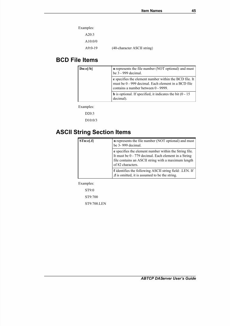
7/26/2019 Allen Bradley TCP Ethernet
http://slidepdf.com/reader/full/allen-bradley-tcp-ethernet 45/102
Item Names 45
ABTCP DAServer User’s Guide
Examples:
A20:3
A10:0/0
A9:0-19 (40-character ASCII string)
BCD File Items
Examples:
D20:3
D10:0/3
ASCII String Section Items
Examples:
ST9:0
ST9:700
ST9:700.LEN
Dn:e[/b] n represents the file number (NOT optional) and must
be 3 - 999 decimal.
e specifies the element number within the BCD file. It
must be 0 - 999 decimal. Each element in a BCD file
contains a number between 0 - 9999.
b is optional. If specified, it indicates the bit (0 - 15
decimal).
STn:e[.f] n represents the file number (NOT optional) and must
be 3- 999 decimal.
e specifies the element number within the String file.
It must be 0 - 779 decimal. Each element in a String
file contains an ASCII string with a maximum length
of 82 characters.
f identifies the following ASCII string field: .LEN. If.f is omitted, it is assumed to be the string.

7/26/2019 Allen Bradley TCP Ethernet
http://slidepdf.com/reader/full/allen-bradley-tcp-ethernet 46/102
46 Chapter 3
ABTCP DAServer User’s Guide
Block Transfer Section Items
Note Block Transfer files are read-only.
Examples:
BT9:0.EN
BT9:3.RLEN
BT9:3.FILE
PID Section Items
WARNING! Access to PID files may degrade the DAServer's performance
due to the extreme size of the PID element (82 words each). If accessing only a
few PIDs at a time, performance will not be greatly affected. If accessing a few
fields of many PIDs at once, it may be faster to move the needed fields to an
intermediate file (Floating Point or Binary) and let the DAServer access theintermediate files.
Examples:
PD9:2.SP
PD9:3.OLH
PD9:0.INI
BTn:e[.f][/b] n represents the file number (NOT optional) and must be 3
- 999 decimal.
e specifies the element number (three words per element)
within the Block Transfer file (0 - 999 decimal).
f identifies one of the valid Block Transfer fields. The validfields for Block Transfer items are listed in the table. If .f is
omitted, it is assumed to be the word containing the status
bits.
b is optional and is normally not used. Specifying the .f
fields can access all of the fields of a Block Transfer.
However, it is possible to use /b to single out a bit in the
.FILE or .ELEM fields (which are words). For Block
Transfer files, the bit number must be 0 - 15 decimal.
PDn:e.f[/b] n represents the file number (NOT optional) and must be
3 - 999 decimal.
e specifies the element number within the PID file. It
must be 0 - 398 decimal.f identifies one of the valid PID fields. The valid fields
for PID files are listed in the table. If PID field .ADDR is
needed, use .ADRE for element and .ADRF for file.
b is optional and is normally not used. All of the fields of
a PID can be accessed by specifying the .f fields. If
specified, it indicates the bit (0 - 15 decimal).

7/26/2019 Allen Bradley TCP Ethernet
http://slidepdf.com/reader/full/allen-bradley-tcp-ethernet 47/102
Item Names 47
ABTCP DAServer User’s Guide
SFC Status Section Items
Examples:
SC9:0
SC9:0.PRE
SC9:0.SA
PLC-5/250 (Pyramid Integrator) Item Naming
The format of item names for data from PLC-5/250 controllers matches the
naming convention used by the programming software. The general form is as
follows:
[$] [module] identifier [file #] : element [.field] [/bit]
Note The parts of the name shown in square brackets ([]) are optional.
$ – Purely optional.
module – PLC-5/250 is comprised of several modules.Use zero to access items in the RM (Resource Manager).
Use 1 - 4 to access items in specific Logic Processors.
Omit the module number when accessing I/O.
identifier – Identifies the section type. The following table summarizes the
supported section types.
file # – File number (0 - 9999 decimal).
If omitted, file 0 is assumed.
element – Element number within the file.
For Input and Output sections, it is also called rack-and-group number,
and must be 0 - 377 octal.For Status section, it must be 0 - 31 decimal.
For all other sections, it must be 0 - 9999 decimal.
.field – Valid only for Counter, Timer, Control, MSG, and PID sections. See the
following table.
/bit – Valid for all sections except Floating Point and String.
SCn:e[.f][/b] n represents the file number (NOT optional) and must
be 3 - 999 decimal.
e specifies the element number within the SFC Status
file. It must be 0 - 999 decimal.
f identifies one of the valid SFC fields. The validfields for SFC files are listed in the table.
b is optional and is normally not used. Specifying the
.f fields can access all of the fields of an SFC. For SFC
Status items, the bit number must be 0 - 15 decimal.
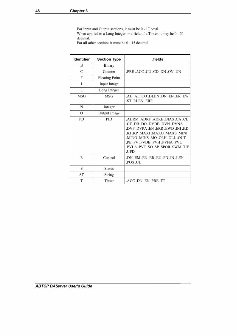
7/26/2019 Allen Bradley TCP Ethernet
http://slidepdf.com/reader/full/allen-bradley-tcp-ethernet 48/102
48 Chapter 3
ABTCP DAServer User’s Guide
For Input and Output sections, it must be 0 - 17 octal.
When applied to a Long Integer or a field of a Timer, it may be 0 - 31
decimal.
For all other sections it must be 0 - 15 decimal.
Identifier Section Type .fields
B Binary
C Counter .PRE .ACC .CU .CD .DN .OV .UN
F Floating Point
I Input Image
L Long Integer
MSG MSG .AD .AE .CO .DLEN .DN .EN .ER .EW
.ST .RLEN .ERR
N Integer
O Output Image
PD PID .ADRM .ADRF .ADRE .BIAS .CA .CL
.CT .DB .DO .DVDB .DVN .DVNA
.DVP .DVPA .EN .ERR .EWD .INI .KD
.KI .KP .MAXI .MAXO .MAXS .MINI
.MINO .MINS .MO .OLH .OLL .OUT
.PE .PV .PVDB .PVH .PVHA .PVL
.PVLA .PVT .SO .SP .SPOR .SWM .TIE
.UPD
R Control .DN .EM .EN .ER .EU .FD .IN .LEN
.POS .UL
S Status
ST StringT Timer .ACC .DN .EN .PRE .TT

7/26/2019 Allen Bradley TCP Ethernet
http://slidepdf.com/reader/full/allen-bradley-tcp-ethernet 49/102
Item Names 49
ABTCP DAServer User’s Guide
Binary Section Items
Examples:
1B3:/159999 (same bit as 1B3:9999/15)
0B:6/4 (same bit as 0B:/100)
Counter Section Items
Examples:
C5:0.ACC
1C9:3.OV
0C:1.PRE
[m]B[n]:e[/b] or
[m]B[n]:/xm indicates the module to access. If not specified, it is
assumed to be 0 (zero), which selects the Resource
Manager. If specified, it must be zero or the
thumbwheel setting for a Logic Processor.
n represents the file number. If not specified, it isassumed to be 0 (zero). If specified, the file number
must be 0 - 9999 decimal.
e specifies the element (word) number within the
Binary file. It must be 0 - 9999 decimal.
b specifies the bit number within the word. The bit
number must be 0 - 15 decimal. If /b is omitted, the
entire word will be accessed as a 16-bit integer.
x specifies the bit number within the file. In this form,
the element number must be omitted and the bit
number may be 0 - 159999.
[m]C[n]:e[.f][/b] m indicates the module to access. If not specified, it is
assumed to be 0 (zero), which selects the Resource
Manager. If specified, it must be 0 (zero) or the
thumbwheel setting for a Logic Processor.
n represents the file number. If not specified, it is
assumed to be 0 (zero). If specified, the file number must be 0 - 9999 decimal.
e specifies the element number (three words per element)
within the Counter file. It must be 0 - 9999 decimal.
.f identifies one of the valid Counter fields. The valid
fields for the Counter section are listed in the table. If .f
is omitted, it is assumed to be the word containing the
status bits.
b is optional and is normally not used. All of the fields of
a Counter can be accessed by specifying the .f fields.
However, it is possible to use /b to single out a bit in the
.PRE or .ACC fields (which are words). For Counter
files, the bit number must be 0 - 15 decimal.

7/26/2019 Allen Bradley TCP Ethernet
http://slidepdf.com/reader/full/allen-bradley-tcp-ethernet 50/102
50 Chapter 3
ABTCP DAServer User’s Guide
Floating Point Section Items
Examples:
F8:0
2F17:3
Input Section Items
Examples:
I:00/0
I:37/17
I:3 4BCD (for 16-bit thumbwheel input)
[m]F[n]:e m indicates the module to access. If not specified, it is
assumed to be 0 (zero), which selects the Resource
Manager. If specified, it must be 0 (zero) or the
thumbwheel setting for a Logic Processor.
n represents the file number. If not specified, it isassumed to be 0 (zero). If specified, the file number must
be 0 - 9999 decimal.
e specifies the element number within the Floating Point
file. It must be 0 - 9999 decimal.
I:rg[/b] Module numbers and file numbers are not allowed.
r indicates the rack number (0 - 37 octal).
g indicates the I/O group (0 - 7 octal).
b specifies the bit (0 - 17 octal). /b may be omitted, if
necessary, to treat the I/O group as a numeric value.

7/26/2019 Allen Bradley TCP Ethernet
http://slidepdf.com/reader/full/allen-bradley-tcp-ethernet 51/102
Item Names 51
ABTCP DAServer User’s Guide
Long Integer Section Items
Examples:
0L:0/31
$L7:0/15
2L15:3
MSG Section Items
Important! Access to MSG files may degrade the DAServer's performance,
due to the extreme size of the MSG file element (56 words each). If accessing
only a few MSG elements at one time, performance will not be affectedgreatly. However, if accessing a few fields of many MSG file elements at once,
it may be faster to move the needed fields to an intermediate file (Binary or
Integer) and let the DAServer access the intermediate files.
Examples:
0MSG0:0.EN
1MSG3:900.DLEN
[m]L[n]:e[/b] m indicates the module to access. If not specified, it is
assumed to be 0 (zero), which selects the Resource
Manager. If specified, it must be zero or the
thumbwheel setting for a Logic Processor.
n represents the file number. If not specified, it isassumed to be 0 (zero). If specified, the file number
must be 0 - 9999 decimal.
e specifies the element number within the Long
Integer file. It must be 0 - 9999 decimal.
b is optional. If specified, it indicates the bit (0 - 31
decimal).
[m]MSG[n]:e[.f] [/b] m indicates the module to access. If not specified, it is
assumed to be 0 (zero), which selects the Resource
Manager. If specified, it must be 0 (zero) or the
thumbwheel setting for a Logic Processor.
n represents the file number. If not specified, it is
assumed to be 0 (zero). If specified, the file number
must be 0 - 9999 decimal.
e specifies the element number within the String file.It must be 0 - 9999 decimal.
.f identifies one of the valid MSG fields. The valid
fields for MSG files are listed in the table.
b is optional and is normally not used. Specifying the
.f fields can access all of the fields of a timer.
However, it is possible to use /b to single out a bit in
the .PRE or .ACC fields (which are words). For Timer
files, the bit number must be 0 - 15 decimal.

7/26/2019 Allen Bradley TCP Ethernet
http://slidepdf.com/reader/full/allen-bradley-tcp-ethernet 52/102
52 Chapter 3
ABTCP DAServer User’s Guide
Integer Section Items
Examples:
0N:0
$N7:0/15
2N15:3
Output Section Items
Examples:
O:00/0
$O:377 4BCD (for 16-bit 7-segment display)
[m]N[n]:e[/b] m indicates the module to access. If not specified, it is
assumed to be 0 (zero), which selects the Resource
Manager. If specified, it must be 0 (zero) or the
thumbwheel setting for a Logic Processor.
n represents the file number. If not specified, it isassumed to be 0 (zero). If specified, the file number must
be 0 - 9999 decimal.
e specifies the element number within the Integer file. It
must be 0 - 9999 decimal.
b is optional. If specified, it indicates the bit (0 - 15
decimal).
O:rg[/b] Module numbers and file numbers are not allowed.
r indicates the rack number (0 - 37 octal).
g indicates the I/O group (0 - 7 octal).
b specifies the bit (0 - 17 octal). /b may be omitted if
necessary to treat the I/O group as a numeric value.

7/26/2019 Allen Bradley TCP Ethernet
http://slidepdf.com/reader/full/allen-bradley-tcp-ethernet 53/102
Item Names 53
ABTCP DAServer User’s Guide
PID Section Items
WARNING! Access to PID files may degrade the DAServer's performance,
due to the extreme size of the PID element (82 words each). If accessing only a
few PIDs at one time, performance will not be affected greatly. However, if
accessing a few fields of many PIDs at once, it may be faster to move the
needed fields to an intermediate file (Floating Point or Binary) and let the
DAServer access the intermediate files.
Examples:
1PD:0.SP
1PD9:3.OLH
0PD1:0.INI
[m]PD[n]:e[.f][/b] m indicates the module to access. If not specified, it is
assumed to be 0 (zero), which selects the Resource
Manager. If specified, it must be 0 (zero) or the
thumbwheel setting for a Logic Processor.
n represents the file number. If not specified, it isassumed to be 0 (zero). If specified, the file number
must be 0 - 9999 decimal.
e specifies the element number within the PID file. It
must be 0 - 9999 decimal.
.f identifies one of the valid PID fields. The valid
fields for PID files are listed in the table. If PID field
.ADDR is needed, use .ADRM for module, .ADRE for
element, or .ADRF for file.
b is optional and is normally not used. Specifying the
.f fields can access all of the fields of a PID. If
specified, it indicates the bit (0 - 15 decimal).

7/26/2019 Allen Bradley TCP Ethernet
http://slidepdf.com/reader/full/allen-bradley-tcp-ethernet 54/102
54 Chapter 3
ABTCP DAServer User’s Guide
Control Section Items
Examples:
1R:0.LEN
R9:3.EM
0R:1.POS
Status Section Items
Examples:
$0S:20 (seconds)
0S0:16 (month)
0S:22/10 (battery low status bit)
[m]R[n]:e[.f][/b] m indicates the module to access. If not specified, it is
assumed to be 0 (zero), which selects the Resource
Manager. If specified, it must be 0 (zero) or the
thumbwheel setting for a Logic Processor.
n represents the file number. If not specified, it isassumed to be 0 (zero). If specified, the file number must
be 0 - 9999 decimal.
e specifies the element number (three words per
element) within the Control file. It must be 0 - 9999
decimal.
.f identifies one of the valid Control fields. The valid
fields for Control files are listed in the table. If .f is
omitted, it is assumed to be the word containing the
status bits.
b is optional and is normally not used. All of the fields of
a Control file can be accessed by specifying the .f fields.
If specified, it indicates the bit (0 - 15 decimal).
[m]S[n]:e[/b] m indicates the module to access. If not specified, it is
assumed to be 0 (zero), which selects the Resource
Manager. If specified, it must be 0 (zero) or the
thumbwheel setting for a Logic Processor.
n represents the file number. If not specified, it is
assumed to be 0 (zero). If specified, the file number must
be 0 - 9999 decimal.
e indicates the element number in the file (0 - 31
decimal).
b is optional. If specified, it indicates the bit (0 - 15
decimal).

7/26/2019 Allen Bradley TCP Ethernet
http://slidepdf.com/reader/full/allen-bradley-tcp-ethernet 55/102
Item Names 55
ABTCP DAServer User’s Guide
String Section Items
Examples:
0ST0:0
1ST3:900
Timer Section Items
Examples:
T:0.ACC
1T9:3.DN
T:1.PRE
SLC-500 Item Naming
The general format of item names for data from SLC-500 controllers matches
the naming convention used by the programming software. The format is as
follows:
[$] identifier [file #] : element [.field] [/bit]
[m]ST[n]:e m indicates the module to access. If not specified, it is
assumed to be 0 (zero), which selects the Resource
Manager. If specified, it must be 0 (zero) or the
thumbwheel setting for a Logic Processor.
n represents the file number. If not specified, it isassumed to be zero. If specified, the file number must
be 0 - 9999 decimal.
e specifies the element number within the String file.
It must be 0 - 9999 decimal. Each element in a String
file contains an ASCII string with a maximum length
of 82 characters.
[m]T[n]:e[.f][/b] m indicates the module to access. If not specified, it is
assumed to be 0 (zero), which selects the Resource
Manager. If specified, it must be 0 (zero) or the
thumbwheel setting for a Logic Processor.
n represents the file number. If not specified, it is
assumed to be 0 (zero). If specified, the file number
must be 0 - 9999 decimal.
e specifies the element number (six words per element)
within the Timer file. It must be 0 - 9999 decimal.
.f identifies one of the valid Timer fields. The validfields for Timer files are listed in the table.
b is optional and is normally not used. Specifying the
.f fields can access all of the fields of a timer. For
Timer files, the bit number must be 0 - 31 decimal.

7/26/2019 Allen Bradley TCP Ethernet
http://slidepdf.com/reader/full/allen-bradley-tcp-ethernet 56/102
56 Chapter 3
ABTCP DAServer User’s Guide
Note The parts of the name shown in square brackets ([]) are optional.
$ – Purely optional.
identifier – Identifies the file type. The following table summarizes the valid
file types, the default file number for each type, and the .fields allowed (if any).
file # – Identifies the file number.
File numbers 0 - 8 decimal are reserved for predefined file types as listed
in the table.
All other file numbers, 9 - 255 decimal, are open to all file types.
element – Element number within the file.
For Input and Output files, it must be 0 - 30 decimal.
For all other file types, it must be 0 - 255 decimal.
.field – Valid only for Counter, Timer and Control files; see the following
table.
/bit – Valid for all file types except ASCII String and Floating Point.
Must be 0 - 15 decimal.
*Available only on certain SL-500 models. Check the Processor Manual for the model being used.
Identifier File TypeDefaultFile # .fields
O Output 0
I Input 1
S Status 2
B Binary 3
T Timer 4 .PRE .ACC .EN .TT .DN
C Counter 5 .PRE .ACC. CU .CD .DN.OV .UN .UA
R Control 6 .LEN .POS .EN .DN .ER
.UL .IN .FD
N Integer 7
F Floating Point* 8
A ASCII* none
ST ASCII String* none

7/26/2019 Allen Bradley TCP Ethernet
http://slidepdf.com/reader/full/allen-bradley-tcp-ethernet 57/102
Item Names 57
ABTCP DAServer User’s Guide
Output File Items
Note The elements in I/O modules are sequentially mapped into a memory
table, and are different from the item names in the PLC programming software.
Refer to the following Addressing SLC I/O Modules section.
Examples:
O0:0/0
$O:2/15
O:3 4BCD (for 16-bit 7-segment display)
Input File Items
Note The elements in I/O modules are sequentially mapped into a memory
table and are different from the item names in the PLC programming software.
Refer to the following Addressing SLC I/O Modules section.
Examples:
I1:0/0
I:2/15
I:3 4BCD (for 16-bit thumbwheel input)
Addressing SLC I/O Modules
The elements (words) in I/O modules are mapped into a memory table. If the
Analog I/O modules are being used, then the point naming will differ from the
point naming in the programming software. The DAServer item name must be
computed from the sum total of words used by the previous input or output blocks. The operator can use the programming software Data Monitor to look
at the memory map of the I file or O file to verify your address. If the address is
unsure, or if the PLC configuration is likely to change, copy the points in
question to the N table or B table, and access the data from there.
O[n]:e[/b] n represents the file number and is optional. If
specified, it must be 0 (zero).
e indicates the element number in the file.
b specifies the bit (0 - 15 decimal). /b may be omitted,
if necessary, to treat the I/O group as a numeric value.
I[n]:e[/b] n represents the file number and is optional. If
specified, it must be 1.
e indicates the element number in the file.
b specifies the bit (0 - 15 decimal). /b may be omitted
if necessary to treat the I/O group as a numeric value.

7/26/2019 Allen Bradley TCP Ethernet
http://slidepdf.com/reader/full/allen-bradley-tcp-ethernet 58/102
58 Chapter 3
ABTCP DAServer User’s Guide
The naming conventions used in the Allen-Bradley programming software are
not supported by the Allen-Bradley Ethernet Direct DAServer. The addressing
convention is similar to that of the PLC-5 family processors. To derive the
correct address for each I/O point, see the following Diagram System. Also see
the following topics, Label I/O Modules with "Word Counts," Sequentially
Number the Input Modules, and Sequentially Number the Output Modules, to
complete addressing the SLC I/O modules.
Diagram System
Addressing of the I/O points begins by drawing a schematic of the system. The
following figure is a diagram of the SLC-5/02 system.
The far left unit is the power supply. From left to right, the modules are:
Label I/O Modules with "Word Counts"
The address of any point within the I/O datatable space, in an SLC processor, is
the sum of the words occupied by previous modules (to the left in the rack) of
the same type. Therefore, to determine the correct address for any particular
point in the I/O datatable, the number of words each module will consume
must be known. Refer to the following list:
1747-L524 SLC-5/02 Module Processor
1746-IA8 8-point 120VAC input module
1746-OA16 16-point 120VAC output module
1746-IA16 16-point 120VAC input module
1746-NI4 4-point 20mA analog input module
1746-NO4I 4-point 20mA analog output module
1746-0A8 8-point 120VAC input module
1746-IB32 32-point DC input module
Number ofWords Module
0 1747-L524 SLC-5/02 Module Processor
1 1746-IA8 8-point 120VAC input module
1 1746-OA16 16-point 120VAC output module
1 1746-IA16 16-point 120VAC input module

7/26/2019 Allen Bradley TCP Ethernet
http://slidepdf.com/reader/full/allen-bradley-tcp-ethernet 59/102
Item Names 59
ABTCP DAServer User’s Guide
Note In the preceding table, the minimum number of words which can beconsumed by a module is 1 (16-bits). This is due to the memory scheme of all
Allen-Bradley processors.
Sequentially Number the Input Modules
In the following I/O diagram, the first input module's addressing should start
with "I:0." As previously noted, this module consumes one datatable word.
Therefore, the addressing of the next INPUT module encounter, moving from
left to right, will begin with "I:1," regardless of the module's physical location.
Sequentially Number the Output Modules
In the following I/O diagram, the first output card encountered is the OA16.Although it is not in the first slot, its address will be "O:0" ("OHH, colon,
ZERO"). This module consumes one datatable word. Therefore, the addressing
of the next OUTPUT module, moving from left to right, will begin with "O:1,"
regardless of the module's physical location.
I/O Diagram
4 1746-NI4 4-point 20mA analog input module
4 1746-NO4I 4-point 20mA analog output module
1 1746-0A8 8-point 120VAC input module
2 1746-IB32 32-point DC input module

7/26/2019 Allen Bradley TCP Ethernet
http://slidepdf.com/reader/full/allen-bradley-tcp-ethernet 60/102
60 Chapter 3
ABTCP DAServer User’s Guide
Status File Items
Note Refer to the SLC-500 Family Processor Manual (Allen-Bradley
Publication) for a complete description of the Status file information.
Examples:
S2:6 (major error fault)
S2:13 (math register)
S:1/5 (forces enabled)
Binary File Items
Examples:
B:33
B:6/4 (same bit as B/100)
B3/4095 (same bit as B:255/15)
S[n]:e[/b] n represents the file number and is optional. If specified,
it must be 2.
e indicates the element number in the file.
b is optional. If specified, it indicates the bit (0 - 15
decimal).
B[n]:e/b or
B[n]/m
n represents the file number and is optional. If not
specified, it is assumed to be 3. If specified, the file
number must be 3 or 9 - 255 decimal.
e specifies the element (word) number within the Binary
file. It must be 0 - 255 decimal.
b specifies the bit number within the word. In the first
form (where :e is present), the bit number must be 0 - 15
decimal.
m also represents the bit number. However, in the second
form, no word numbers are specified and the bit number
may be 0 - 4095.

7/26/2019 Allen Bradley TCP Ethernet
http://slidepdf.com/reader/full/allen-bradley-tcp-ethernet 61/102
Item Names 61
ABTCP DAServer User’s Guide
Timer File Items
Examples:T4:0.ACC
T4:3.DN
T4:1.PRE
Counter File Items
Examples:
C5:0.ACC
C5:3.OV
C5:1.PRE
T[n]:e[.f][/b] n represents the file number and is optional. If not
specified, it is assumed to be 4. If specified, the file
number must be 4 or 9 - 255 decimal.
e specifies the element number (three words per
element) within the Timer file. It must be 0 - 255decimal.
.f identifies one of the valid Timer fields. The valid
fields for Timer Files are listed in the table. If .f is
omitted, it is assumed to be the word containing the
status bits.
b is optional and is normally not used. All of the fields
of a timer can be accessed by specifying the .f fields.
However, it is possible to use /b to single out a bit in
the .PRE or .ACC fields (which are words). The bit
number must be 0 - 15 decimal.
C[n]:e[.f][/b] n represents the file number and is optional. If not
specified, it is assumed to be 5. If specified, the file
number must be 5 or 9 - 255 decimal.
e specifies the element number (three words per
element) within the Counter file. It must be 0 - 255
decimal.
.f identifies one of the valid Counter fields. The valid
fields for the Counter Files are listed in the table. If .f is
omitted, it is assumed to be the word containing the
status bits.
b is optional and is normally not used. Specifying the .f
fields can access all of the fields of a counter. However,
it is possible to use /b to single out a bit in the .PRE or
.ACC fields (which are words). The bit number must
be 0 - 15 decimal.

7/26/2019 Allen Bradley TCP Ethernet
http://slidepdf.com/reader/full/allen-bradley-tcp-ethernet 62/102
62 Chapter 3
ABTCP DAServer User’s Guide
Control File Items
Examples:
R6:0.LEN
R6:3.EN
R6:1.POS
Integer File Items
Examples:
N7:0
N7:0/15
N7:3
R[n]:e[.f][/b] n represents the file number and is optional. If not
specified, it is assumed to be 6. If specified, the file
number must be 6 or 9 - 255 decimal.
e specifies the element number (three words per element)
within the Control file. It must be 0 - 255 decimal.f identifies one of the valid Control fields. The valid
fields for the Control files are listed in the table. If .f is
omitted, it is assumed to be the word containing the
status bits.
b is optional and is normally not used. All of the fields of
a Control file can be accessed by specifying the .f fields.
However, it is possible to use /b to single out a bit in the
.LEN or .POS fields (which are words). The bit number
must be 0 - 15 decimal.
N[n]:e[/b] n represents the file number and is optional. If not
specified, it is assumed to be 7. If specified, the file
number must be 7 or 9 - 255 decimal.
e specifies the element number within the Integer file. It
must be 0 - 255 decimal.
b is optional. If specified, it indicates the bit (0 - 15
decimal).

7/26/2019 Allen Bradley TCP Ethernet
http://slidepdf.com/reader/full/allen-bradley-tcp-ethernet 63/102
Item Names 63
ABTCP DAServer User’s Guide
Floating Point File Items
Examples:
F8:0
F8:3
ASCII File Items
Examples:
A20:3
A10:0/0
ASCII String Section Items
Examples:
ST9:0
ST9:200
DAServer Standard System ItemsSystem items supply DAServer users with easy access to DAServer status and
diagnostic information. They are treated just like ordinary items with respect to
the client. However, in most cases these items are not directly acquired via the
communications layer. System item values are usually generated through
internal calculations, measurements, and tracking of the DAS Engine.
No DAServer-specific system items are provided in this DAServer.
F[n]:e n represents the file number and is optional. If not
specified, it is assumed to be 8. If specified, the file
number must be 8 - 255 decimal.
e specifies the element number within the Floating Point
file. It must be 0 - 255 decimal.
An:e[/b] n represents the file number (NOT optional) and must
be 9 - 255 decimal.
e specifies the element number within the ASCII file.
It must be 0 - 255 decimal. Each element in an ASCIIfile contains two ASCII characters.
b is optional. If specified, it indicates bit (0 - 15
decimal).
STn:e n represents the file number (NOT optional) and must be 9 - 255 decimal.
e specifies the element number within the String file. It
must be 0 - 255 decimal. Each element in a String file
contains an ASCII string with a maximum length of 78
characters.

7/26/2019 Allen Bradley TCP Ethernet
http://slidepdf.com/reader/full/allen-bradley-tcp-ethernet 64/102
64 Chapter 3
ABTCP DAServer User’s Guide
System items, like ordinary items, are defined by the following properties:
• Group (client group/OPC group): Arbitrary collection of items, not
correlated.
• Hierarchical location (link name/OPC path – the hierarchical node section
of the fully qualified OPC item ID): The device the item is attached to.
• Device group (OPC access path/topic, or a Scan Group on a hierarchical branch): Collection of items on the same physical location with the same
protocol update rate.
Example:
To check the status of an external device, the reference might be:
ABTCPIP.ABPLC1.$SYS$Status
Note This syntax does not refer to the access path/device group. As long as
the data requested is from the same external device, the value will always be
the same.
Note For DDE/SuiteLink clients, $SYS$Status always comes from the leaflevel of a DAServer hierarchy branch, which is the destination PLC node. For
OPC clients, $SYS$Status can be accessed at all hierarchy levels. $SYS$Status
at the root level of the whole hierarchy tree is always good, as it represents the
quality status of the local computer itself. Hence, for practical application,
OPC clients should reference $SYS$Status at any hierarchy levels other than
the root.
In the ArchestrA context, the device group plays the most important role of
identifying the scope of any item (the device group defines the hierarchical
location implicitly when using globally unique device-group names, which is
required for DDE/SuiteLink compatibility).
All system items follow the same naming convention:
• All system items start with $SYS$.
• The DAS Engine scans and parses the name for system items.
• Parsing of the name is case-insensitive.
All system items can be accessed through subscriptions to a device group.
However, while some system items return data for that device group, others are
server-wide.
DAServer Global System ItemThe following system item refers to specific information regarding a global
condition of the DAServer.

7/26/2019 Allen Bradley TCP Ethernet
http://slidepdf.com/reader/full/allen-bradley-tcp-ethernet 65/102
Item Names 65
ABTCP DAServer User’s Guide
DAServer Device-Specific System Items
The following system items refer to specific information regarding thedevice(s) the DAServer is connected to.
System Item Name
Type/AccessRights Description Values
$SYS$Licensed Boolean/
Read
Binary status indication of the existence
of a valid license for the DAServer.If FALSE, this item causes the DAServer
to stop updating existing tags, refuse
activation of new tags, and reject write
requests, in addition to setting quality for
all items to BAD.
If TRUE, the DAServer functions as
configured. All instances have the same
value.
RANGE: 0, 1
1: Valid license exists or
the DAServer is in Demo
mode.
0: No valid license exists.
System Item Name(Type)
Type/AccessRights Description Values
$SYS$Status Boolean/
Read
Binary status indication of the connection
state to the device (hierarchy level) the
item is attached to. The device group
(OPC access path/topic) does not affect
the value.
The status can be good even if individualitems have errors.
For DDE/SuiteLink clients, $SYS$Status
always comes from the leaf level of a
DAServer hierarchy branch, which is the
destination PLC node.
For OPC clients, $SYS$Status can be
accessed at all hierarchy levels.
$SYS$Status at the root level of the whole
hierarchy tree is always good, as it
represents the quality status of the local
computer itself. Hence, for practical
application, OPC clients should reference
$SYS$Status at any hierarchy levels otherthan the root.
RANGE: 0, 1
1: DAServer connection
to the device is intact.
0: Error communicating
with the device.

7/26/2019 Allen Bradley TCP Ethernet
http://slidepdf.com/reader/full/allen-bradley-tcp-ethernet 66/102
66 Chapter 3
ABTCP DAServer User’s Guide
$SYS$ErrorCode Longint/
Read
Detailed error code of the
communications state to the device.
The device group (OPC access path/topic)
does not affect the value.
>= 0: Good status (0 is
the default state –
connected.
>0: Is some device
state, like: connecting,
initializing, and so on.
<0: Error status (value
indicates the error).
$SYS$ErrorText String/Read Detailed error string of the
communications state of the device.
The device group (OPC access path/topic)
does not affect the value.
Descriptive text for the
communications state
corresponding to the
error code.
$SYS$StoreSettings Integer/
ReadWrite
Used to make the temporary update
interval changes via the
$SYS$UpdateInterval item permanent.
If the client pokes a value of 1 into this
system item, the currently set update
interval is written to the DAServer’s
configuration file.
The value of this system item clears to 0
after being set, if the configuration file
write is successful. If the write fails, then
the value is set to -1.
If the update interval has been changed via
the $SYS$UpdateInterval item and this
item is not poked to 1, the DAServer uses
the original update interval for that topic
the next time it is started.Reading the item always provides 0.
ReadWrite values are persisted only if the
user sets this system item. The values
other than this persist only for the life of
the DAServer.
RANGE: -1, 0, 1
0: Read value always if
status is OK.
1: Persist settings
(cleared immediately).
-1: Error occurred
during saving the
configuration file
System Item Name(Type)
Type/AccessRights Description Values

7/26/2019 Allen Bradley TCP Ethernet
http://slidepdf.com/reader/full/allen-bradley-tcp-ethernet 67/102
Item Names 67
ABTCP DAServer User’s Guide
DAServer Device-Group-Specific System Items
The following system items refer to specific information regarding device
groups that have been configured in the DAServer.
System Item Name(Type)
Type/AccessRights Description Values
$SYS$UpdateInterval DWord/
ReadWrite
Used to access the currently set update
interval. It is the current update interval
of the device group in milliseconds. A
client can poke new values into this
item.
The value of zero indicates that no non-
system items on that topic are updated
(data for these items are not acquired
from the device).
RANGE: 0…2147483647
0: Topic inactive, no items
are updated. Data
acquisition is stopped.
>0: Expected updated
interval for the set of all
items in the device group.
$SYS$MaxInterval DWord/Read
Used to access the currently measuredmaximum update interval in
milliseconds of all items of the
corresponding device group. This item
is read-only.
The value of the slowest item is
displayed.
RANGE: 0…2147483647
0: If update interval is 0 or
if the status is false.
>0: Measured update
interval.
$SYS$WriteComplete Integer/
ReadWrite
Used to access the state of pending
write activities on the corresponding
device group.
On the device group creation (adding
items to an OPC group), the value of
this system item is initially 1, indicating
all write activities are complete – no
pokes are pending.
If values are poked into any items of the
device group, the value of this item
changes to 0, indicating write activity is
currently in progress.
If the DAServer has completed all write
activities, the value of this item changes
to 1 if all pokes were successful, or to -1
if at least one poke has failed.
If the value of this item is not zero, the
client can poke 1 or -1 to it (poke a 1 to
clear errors or a -1 to test a clientreaction on write errors).
If the value of this item is zero, it cannot
be poked.
RANGE: -1, 0, 1
1: Write complete (no
writes are pending – initial
state).
0: Writes are pending.
-1: Writes completed with
errors.

7/26/2019 Allen Bradley TCP Ethernet
http://slidepdf.com/reader/full/allen-bradley-tcp-ethernet 68/102
68 Chapter 3
ABTCP DAServer User’s Guide
$SYS$ReadComplete Integer/
ReadWrite
Used to access the state of initial reads
on all items in the corresponding device
group. The value is 1 if all active items
in a device group have been read at least
once.
If at least one item in the device group
is activated, this item changes to 0. It
changes to 1 if all items have been read
successfully or to -1 if at least one item
has a non-good quality.
Poking a 0 to this item resets the
internal read states of all items in this
device group. This resets this item to 0.
If all items are read again after this
poke, this item changes back to 1 or -1.
RANGE: -1, 0, 1
1: Read complete (all
values have been read).
0: Not all values have
been read.
-1: All values have been
read but some have a non-
good quality.
$SYS$ItemCount DWord/Read
Used to access the number of items inthe corresponding device group. This
item is read-only.
RANGE: 0…2147483647
>=0: Number of active
items.
$SYS$ActiveItemCount DWord/
Read
Used to access the number of active
items in the corresponding device
group. This item is read-only.
RANGE: 0…2147483647
>=0: Number of active
items.
$SYS$ErrorCount DWord/
Read
Used to access the number of all items
(active and inactive) that have errors
(non-good OPC quality) in the
corresponding topic.
If the communications status of a devicegroup is bad, all items have errors. This
item is read-only.
RANGE: 0…2147483647
>=0: Number of all items
(active and inactive) with
errors.
$SYS$PollNow Boolean/
ReadWrite
Poking a 1 to this item forces all items
in the corresponding device group to be
read immediately (all messages in this
device group become due).
This is useful if you want to force to get
the newest values from the device,
regardless of its update interval. This
also works on device groups with a zero
update interval (manual protocol
triggering).
RANGE: 0, 1
System Item Name(Type)
Type/AccessRights Description Values

7/26/2019 Allen Bradley TCP Ethernet
http://slidepdf.com/reader/full/allen-bradley-tcp-ethernet 69/102
Item Names 69
ABTCP DAServer User’s Guide
Generic OPC Syntax
A DAServer serves as a container for OPC Groups, which provide the
mechanism for containing and logically organizing OPC items. Within eachOPC Group, an OPC-compliant client can register OPC items, which represent
connections to data sources in the field device. In other words, all access to
OPC items is maintained through the OPC Group.
The fully qualified name for an OPC item is called the Item ID (equivalent to
Item Name). The syntax for specifying a unique Item ID is DAServer-
dependent. In OPC data acquisition servers, the syntax can be as follows:
AREA10.VESSEL1.TIC1.PLC.N7:11
where each component (delimited by a period) represents a branch or leaf of
the field device’s hierarchy.
In this example:
• AREA10.VESSEL1.TIC1 is the link name for a DAServer.
• PLC is the name of the target PLC.
• N7:11 is the specific data point (Item) desired.
• An item is typically a single value, such as an analog, digital, or string
value.
Where Item ID describes the syntax for defining the desired data point, OPC
provides for another parameter, called Access Path, that defines optional
specifications for obtaining that data. In DAServers, Access Paths are
equivalent to Device Groups. In DAServers, it is this parameter that is used to
define the update interval between the DAServer and the field device for
accessing the values of data points in the PLC.

7/26/2019 Allen Bradley TCP Ethernet
http://slidepdf.com/reader/full/allen-bradley-tcp-ethernet 70/102
70 Chapter 3
ABTCP DAServer User’s Guide
7/26/2019 Allen Bradley TCP Ethernet
http://slidepdf.com/reader/full/allen-bradley-tcp-ethernet 71/102
Troubleshooting 71
ABTCP DAServer User’s Guide
C H A P T E R 4
Troubleshooting
This chapter describes troubleshooting tools you can use to deal with the
ABTCP DAServer problems you may encounter.
The DAServer Manager provides access to diagnostics and other statistical
data, and the Log Viewer provides access to event messages logged during the
operation of a DAServer. Also, your client (for example, InTouch) can monitor
connectivity with the PLC through the $SYS$Status item. Use these tools
together with the information in this section to troubleshoot your ABTCP
DAServer.
Note In order to determine the version of your DAServer, the following steps
need to be performed. Search for DASABTCP.dll, right-click on the File
Name, select Properties on the shortcut menu, and select the Version tab on
the Properties dialog box. The version of your DAServer is listed under File
Version.
Contents
• Monitoring Connectivity Status with the PLC
• Monitoring the Status of DAS Conversations
• Error Messages
Monitoring Connectivity Status with the PLC
The built-in discrete item, $SYS$Status, can be used to monitor the status of
communications with the PLC. This item is set to:
• 0 (zero) when communications with the PLC fails.
• 1 (one) when communications is successful.
Note For DDE/SuiteLink clients, $SYS$Status always comes from the leaf
level of a DAServer hierarchy branch, which is the destination PLC node. For
OPC clients, $SYS$Status can be accessed at all hierarchy levels. $SYS$Status
at the root level of the whole hierarchy tree is always good, as it represents the
quality status of the local computer itself. Hence, for practical application,
OPC clients should reference $SYS$Status at any hierarchy levels other than
the root.

7/26/2019 Allen Bradley TCP Ethernet
http://slidepdf.com/reader/full/allen-bradley-tcp-ethernet 72/102
72 Chapter 4
ABTCP DAServer User’s Guide
Enter the following DDE reference formula in the appropriate place in your
client:
=DASABTCP|ABPLC!$SYS$Status
where:
DASABTCP is the name of the DAServer application.
ABPLC is the exact device group defined in the DAServer
for the PLC.
$SYS$Status is the discrete item used to monitor the status of
connectivity with the PLC.
Enter the following OPC item reference syntax when adding the item in your
OPC client:
YourOPCAccessPath.$SYS$Status
where:
YourOPCAccessPath is the assembly of hierarchy node names leading
to a specific controller device.
$SYS$Status is the discrete item used to monitor the status of
connectivity with the controller device.
Note In the case of a PLC disconnect, the DAServer will retry three times
before entering into slow poll mode. In the case of reply time-out, the
DAServer will go into slow poll mode immediately.
Monitoring the Status of DAS Conversations
The InTouch WindowViewer supports built-in topic names, calledDDEStatus and IOStatus, that can be used to monitor the status of specific
DAS conversations. For example, let us assume that WindowViewer (VIEW)
is communicating with the ABTCP DAServer to a PLC that has been defined
in the DAServer with the topic name ABPLC.
The discrete items, DDEStatus and IOStatus, are set to 0 (zero) when this
DAS conversation failed, and to 1 (one) when this DAS conversation is
successful.
Using DDEStatus and IOStatus in Excel
The status of communications between the PLC and InTouch can be read into
Excel by entering the following DDE reference formula in a cell on aspreadsheet:
=view|DDEStatus!ABPLC
or
=view|IOStatus!ABPLC

7/26/2019 Allen Bradley TCP Ethernet
http://slidepdf.com/reader/full/allen-bradley-tcp-ethernet 73/102
Troubleshooting 73
ABTCP DAServer User’s Guide
where:
view is the name of the InTouch application.
[DDE][IO] Status is the built-in topic name used to monitor the status
of communications between the DAServer and
InTouch.
ABPLC is the exact topic name defined in the DAServer forthe PLC.
Reading Values from the DAServer into Excel
Values may be read directly into Excel spreadsheets from the DAServer by
entering a DDE formula into a cell using the following format:
=applicationname|topicname!itemname
Example formula:
=DASABTCP|ABPLC!'N7:0'
where:
DASABTCP is the name of the DAServer application.
ABPLC is the exact topic name defined in the DAServer for the
PLC.
N7:0 Is the actual location in the PLC that contains the data
value. This is the item name.
In this example, each time the value of N7:0 changes in the PLC, the
DAServer will automatically send the new value to the cell containing the
formula in Excel.
Note Refer to the Microsoft Excel manual for complete details on entering
Remote Reference formulas for cells.
Writing Values to the DAServer from Excel
Values may be written to the DAServer from Microsoft Excel by creating an
Excel macro that uses the POKE command. The proper command is entered in
Excel as follows:
channel=INITIATE("applicationname","topicname")
=POKE(channel,"itemname", Data_Reference)
=TERMINATE (channel)
=RETURN()
The following describes each of the above POKE macro statements:
channel=INITIATE("applicationname","topicname")
• Opens a channel to a specific topic name (defined in the DAServer) in
a particular application name (the executable name less the .exe).
• Assigns the number of that opened channel to channel.
7/26/2019 Allen Bradley TCP Ethernet
http://slidepdf.com/reader/full/allen-bradley-tcp-ethernet 74/102
74 Chapter 4
ABTCP DAServer User’s Guide
Note By using the channel=INITIATE statement, the word channel must be
used in the =POKE statement instead of the actual cell reference. The
"application name" and "topic name" portions of the formula must be
enclosed in quotation marks.
=POKE(channel,"itemname", Data_Reference)
• POKEs the value contained in the Data_Reference to the specified
item name (actual location in the PLC), via the channel number
returned by the previously executed INITIATE function.
• Data_Reference is the row/column ID of the cell containing the data
value.
=TERMINATE(channel)
• Closes the channel at the end of the macro.
• Some applications have a limited number of channels; therefore, they
should be closed when finished.
• Channel is the channel number returned by the previously executed
INITIATE function.
=RETURN()
• Marks the end of the macro.
Note Refer to the .XLM sample Excel poke macro provided on the DAServer
CD. Also refer to the Microsoft Excel manual for complete details on entering
Remote Reference formulas for cells.
Error Messages
Generic DAServer error messages, ABTCP-DAServer-specific error
messages, and controller-specific error messages are supported. These error
messages are sent to the Log Viewer. Use the Log Flag data to customize the
type of messages logged to the Log Viewer, and see the Log Viewer
documentation for more information about using log flags.
To troubleshoot DAServer problems, use the following error messages
together with the DAServer Manager Diagnostics root data.
ABTCP DAServer Error Messages
The following table lists all the generic-DAServer and ABTCP-DAServer-
specific error messages.

7/26/2019 Allen Bradley TCP Ethernet
http://slidepdf.com/reader/full/allen-bradley-tcp-ethernet 75/102
Troubleshooting 75
ABTCP DAServer User’s Guide
Error Message Explanation Possible Cause Solution
PLC connection attempt
timed out, closing socket
at <Time unit in Msec>
The TCPIP socket was
closed due to time-out
when attempted to
connect to the PLC.
1. The network has not
been set up correctly or is
having a problem.
2. The PLC is not set upor is having a problem.
1. Make sure the network
is set up and running
correctly.
2. Make sure the PLC isset up and running
correctly.
PLC message timed out,
revoking message
<Message ID> at <Time
unit in Msec>
The message was
revoked due to time-out
while waiting for a
response from the PLC.
1. The network
communications is
having a problem.
2. The PLC is having a
problem communicating.
1. Make sure the network
is functioning.
2. Make sure the PLC is
functioning.
runt Unsolicited msg
packet received on <Host
IP Address>
Invalid unsolicited
message packet was
received.
The PLC is not set up
correctly.
Set up the PLC for
unsolicited message
communications.
Maximum number of
socket <MAX> exceeded
Exceeded the maximum
number of TCPIPsockets allowed.
The maximum number of
sockets allowed isexceeded.
Free socket usage.
Error encountered
initializing Unsolicited
Data Port. No direct (i.e.:
peer-to-peer) unsolicited
data will be accepted.
Failed to create a TCPIP
socket for the "peer-to-
peer" unsolicited data
used. Result: no
unsolicited data can be
accepted.
1. The network
communications is
having a problem.
2. The PLC is having a
problem communicating.
1. Make sure the network
is functioning.
2. Make sure the PLC is
functioning.
WSAStartup() returned
<Error Code>
Error code returned by
the failing WinSocket
Initialization routine.
Failed to initialize a
Window Socket in the
system, due to an internal
system error.
Check the returned error
code against the
Microsoft error code list
to fix the WinSock
initialization problem.
Winsock description:
<Description string>
When the verbose flag is
on, this message is
displayed after the
preceding WinSocket
initialization failing
message.
This message contains a
brief description for the
error code returned.
More description for the
preceding failing
WinSocket initialization
routine.
Check the description
and fix the problem
according to Microsoft’s
error list.
Winsock sys status:
<Status string>
When the verbose flag is
on, this message is
displayed after the preceding WinSocket
initialization failing
message.
This message contains a
brief status string for the
error code returned.
More description for the
preceding failing
WinSocket initializationroutine.
Check the description
and fix the problem
according to Microsoft’serror list.

7/26/2019 Allen Bradley TCP Ethernet
http://slidepdf.com/reader/full/allen-bradley-tcp-ethernet 76/102
76 Chapter 4
ABTCP DAServer User’s Guide
Rejected <PLC Type>
ITEM = <Item Name>
on plc <PLC Name with
hierarchy path>
The item requested by
the client was rejected.
1. The requested item
syntax was incorrect.
2. The hierarchy PLC
name was incorrect.
1. Correct the syntax of
the item.
2. Correct the hierarchy
path for the PLC name.
A floating point valueread for Item: [ITEM] on
Topic: [TOPIC] was
NOT A VALID
NUMBER (Negative
Infinity), therefore, it
was converted to -3.4e38
A bad negative floatingvalue was read from the
PLC.
The value was changed
by the DAServer to a
known good value before
sending it to the client.
Bad data was read. None.
A floating point value
read for Item: [ITEM] on
Topic: [TOPIC] was
NOT A VALID
NUMBER (Positive
Infinity), therefore, itwas converted to
+3.4e38
A bad positive floating
value was read from the
PLC.
The DAServer changed
the value to a known
good value beforesending it to the client.
Bad data was read. None.
A floating point value
read for Item: [ITEM] on
Topic: [TOPIC] was
NOT A VALID
NUMBER (!NaN!),
therefore, it was
converted to +3.4e38
A bad positive floating
value was read from the
PLC. The DAServer
changed the value to a
known good value before
sending it to the client.
Bad data was read. None.
Could not find PLC node
when creating message
Failed to find the PLC
node from the hierarchy
from the message.
When creating the
message for the item, the
DAServer cannot locate
the PLC node. Possible
corrupted or bad CFG
file.
Check and correct the
CFG file.
Response code
[CmdNum# from reply]
different from command
code [CmdNum# from
original request]
The response message’s
command code does not
match the original
command code.
This error indicates
something is very wrong.
Either the PLC is bad or
the communications
between the PLC and the
computer is bad – in such
a way that wrong data is
passing between the
DAServer and the PLC.
Make sure the DAServer
is running correctly.
Make sure the PLC is
running correctly. Restart
both the PLC and the
DAServer if needed.
Error Message Explanation Possible Cause Solution
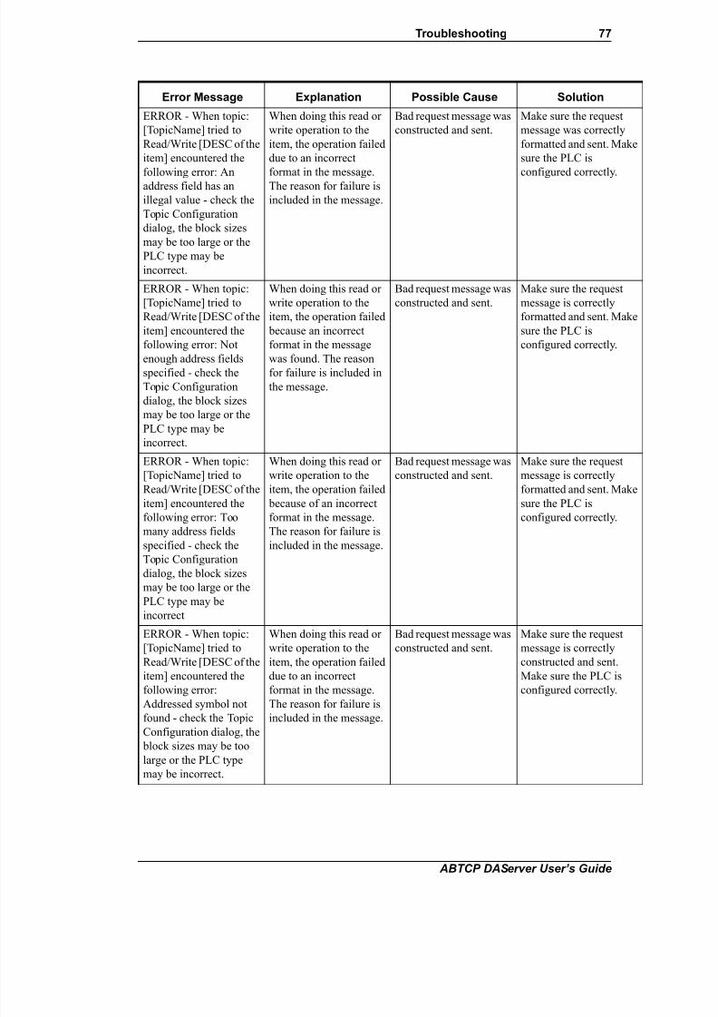
7/26/2019 Allen Bradley TCP Ethernet
http://slidepdf.com/reader/full/allen-bradley-tcp-ethernet 77/102
Troubleshooting 77
ABTCP DAServer User’s Guide
ERROR - When topic:
[TopicName] tried to
Read/Write [DESC of the
item] encountered the
following error: Anaddress field has an
illegal value - check the
Topic Configuration
dialog, the block sizes
may be too large or the
PLC type may be
incorrect.
When doing this read or
write operation to the
item, the operation failed
due to an incorrect
format in the message.
The reason for failure is
included in the message.
Bad request message was
constructed and sent.
Make sure the request
message was correctly
formatted and sent. Make
sure the PLC is
configured correctly.
ERROR - When topic:
[TopicName] tried to
Read/Write [DESC of the
item] encountered the
following error: Not
enough address fieldsspecified - check the
Topic Configuration
dialog, the block sizes
may be too large or the
PLC type may be
incorrect.
When doing this read or
write operation to the
item, the operation failed
because an incorrect
format in the message
was found. The reasonfor failure is included in
the message.
Bad request message was
constructed and sent.
Make sure the request
message is correctly
formatted and sent. Make
sure the PLC is
configured correctly.
ERROR - When topic:
[TopicName] tried to
Read/Write [DESC of the
item] encountered the
following error: Too
many address fieldsspecified - check the
Topic Configuration
dialog, the block sizes
may be too large or the
PLC type may be
incorrect
When doing this read or
write operation to the
item, the operation failed
because of an incorrect
format in the message.
The reason for failure isincluded in the message.
Bad request message was
constructed and sent.
Make sure the request
message is correctly
formatted and sent. Make
sure the PLC is
configured correctly.
ERROR - When topic:
[TopicName] tried to
Read/Write [DESC of the
item] encountered the
following error:
Addressed symbol not
found - check the Topic
Configuration dialog, the
block sizes may be too
large or the PLC type
may be incorrect.
When doing this read or
write operation to the
item, the operation failed
due to an incorrect
format in the message.
The reason for failure is
included in the message.
Bad request message was
constructed and sent.
Make sure the request
message is correctly
constructed and sent.
Make sure the PLC is
configured correctly.
Error Message Explanation Possible Cause Solution

7/26/2019 Allen Bradley TCP Ethernet
http://slidepdf.com/reader/full/allen-bradley-tcp-ethernet 78/102
78 Chapter 4
ABTCP DAServer User’s Guide
ERROR - When topic:
[TopicName] tried to
Read/Write [DESC of the
item] encountered the
following error:Addressed symbol is > 8
or <= 0 length - check the
Topic Configuration
dialog, the block sizes
may be too large or the
PLC type may be
incorrect.
When doing this read or
write operation to the
item, the operation failed
because an incorrect
format in the messagewas found. The reason
for failure is included in
the message.
Bad request message was
constructed and sent.
Make sure the request
message is correctly
formatted and sent. Make
sure the PLC is
configured correctly.
ERROR - When topic:
[TopicName] tried to
Read/Write [DESC of the
item] encountered the
following error: This
address does not exist inPLC - check Data Table
definition inside PLC
and make sure ALL
requested points are
defined.
When doing this read or
write operation to the
item, the operation failed
due to an incorrect
format in the message.
The reason for failure isincluded in the message.
Bad request message was
constructed and sent.
Make sure the request
message is correctly
constructed and sent.
Make sure the PLC is
configured correctly.
ERROR - When topic:
[TopicName] tried to
Read/Write [DESC of the
item] encountered the
following error: One or
more points specified
within this message donot exist in the PLC's
Data Table - Please
define, inside the PLC,
the missing point(s).
When doing this read or
write operation to the
item, the operation failed
because an incorrect
format in the message
was found. The reason
for failure is included inthe message.
Bad request message was
constructed and sent.
Make sure the request
message is correctly
formatted and sent. Make
sure the PLC is
configured correctly.
ERROR - When topic:
[TopicName] tried to
Read/Write [DESC of the
item] encountered the
following error: Cannot
complete request; the
situation inside the PLC
and/or bridge devices has
changed since the
command started.
When doing this read or
write operation to the
item, the operation failed
due to an incorrect
format in the message.
The reason for failure is
included in the message.
Bad request message was
constructed and sent.
Make sure the request
message is correctly
constructed and sent.
Make sure the PLC is
configured correctly.
Error Message Explanation Possible Cause Solution

7/26/2019 Allen Bradley TCP Ethernet
http://slidepdf.com/reader/full/allen-bradley-tcp-ethernet 79/102
Troubleshooting 79
ABTCP DAServer User’s Guide
ERROR - When topic:
[TopicName] tried to
Read/Write [DESC of the
item] encountered the
following error: Data orFile is too large - the
packet the PLC is trying
to send back is too large -
check the Topic
Configuration dialog.
When doing this read or
write operation to the
item, the operation failed
due to an incorrect
format in the message.
The reason for failure is
included in the message.
Bad request message was
constructed and sent.
Make sure the request
message is correctly
formatted and sent. Make
sure the PLC is
configured correctly.
ERROR - When topic:
[TopicName] tried to
Read/Write [DESC of the
item] encountered the
following error:
Transaction size too large
for protocol - check the
Topic Configurationdialog, the block sizes
may be too large or the
PLC type may be
incorrect.
When doing this read or
write operation to the
item, the operation failed
because of an incorrect
format in the message.
The reason for failure is
included in the message.
Bad request message was
constructed and sent.
Make sure the request
message is correctly
formatted and sent. Make
sure the PLC is
configured correctly.
ERROR - When topic:
[TopicName] tried to
Read/Write [DESC of the
item] encountered the
following error: Access
Denied; improper
privilege - the PLC has
refused us access to oneor more of the data points
in this message - check
PRIVILEGE settings
inside PLC.
When doing this read or
write operation to the
item, the operation failed
due to an incorrect
format in the message.
The reason for failure is
included in the message.
Bad request message was
constructed and sent.
Make sure the request
message is correctly
formatted and sent. Make
sure the PLC is
configured correctly.
ERROR - When topic:
[TopicName] tried to
Read/Write [DESC of the
item] encountered the
following error: A
resource is not available -
A programming terminal
may be connected to
(communicating with)
this PLC - please
disconnect the
programming terminal.
When doing this read or
write operation to the
item, the operation failed
because of an incorrect
format in the message.
The reason for failure is
included in the message.
Write to read/write to a
PLC that is already
connected to a
programming terminal.
Disconnect the
programming terminal to
the PLC and repeat the
read/write operation.
Error Message Explanation Possible Cause Solution

7/26/2019 Allen Bradley TCP Ethernet
http://slidepdf.com/reader/full/allen-bradley-tcp-ethernet 80/102
80 Chapter 4
ABTCP DAServer User’s Guide
ERROR - When topic:
[TopicName] tried to
Read/Write [DESC of the
item] encountered the
following error:Condition already exists;
resource is already
available - a loss of
communications
synchronization has
occurred - if it continues,
restart the DAServer.
When doing this read or
write operation to the
item, the operation failed
because of an incorrect
format in the message.The reason for failure is
included in the message.
Bad request message was
constructed and sent.
Make sure the request
message is correctly
constructed and sent. If
error continues, restart
the DAServer and repeatthe read/write operation.
ERROR - When topic:
[TopicName] tried to
Read/Write [DESC of the
item] encountered the
following error:
Command cannot beexecuted - the PLC has
refused to execute the
command we have sent
to it - check the PLC type
in the Topic
Configuration dialog.
When doing this read or
write operation to the
item, the operation failed
due to an incorrect
format in the message.
The reason for failure isincluded in the message.
Bad request message was
constructed and sent.
Make sure the request
message is correctly
formatted and sent. Make
sure the PLC is
configured correctly.
ERROR - When topic:
[TopicName] tried to
Read/Write [DESC of the
item] encountered the
following error: No
Access - the PLC hasrefused us access to one
or more of the data points
in this message - check
PRIVILEGE settings
inside the PLC.
When doing this read or
write operation to the
item, the operation failed
because an incorrect
format in the message
was found. The reasonfor failure is included in
the message.
Cannot access the PLC. Make sure the PLC is
configured correctly.
Repeat the read/write
operation after correcting
the configuration.
ERROR - When topic:
[TopicName] tried to
Read/Write [DESC of the
item] encountered the
following error: The data
type requested (see
FileType parameter) may
not match the data type
for the specified file
number inside the PLC.
When doing this read or
write operation to the
item, the operation failed
due to an incorrect
format in the message.
The reason for failure is
included in the message.
Bad request message was
constructed and sent.
Make sure the request
message is correctly
formatted and sent. Make
sure the PLC is
configured correctly.
Error Message Explanation Possible Cause Solution

7/26/2019 Allen Bradley TCP Ethernet
http://slidepdf.com/reader/full/allen-bradley-tcp-ethernet 81/102
Troubleshooting 81
ABTCP DAServer User’s Guide
ERROR - When topic:
[TopicName] tried to
Read/Write [DESC of the
item] encountered the
following error: The PLChas rejected the format of
our command - check the
Topic Configuration
dialog, the block sizes
may be too large or the
PLC type may be
incorrect.
When doing this read or
write operation to the
item, the operation failed
because of an incorrect
format in message. The
reason for failure is
included in the message.
Bad request message was
constructed and sent.
Make sure the request
message is correctly
formatted and sent. Make
sure the PLC is
configured correctly.
ERROR - When topic:
[TopicName] tried to
Read/Write [DESC of the
item] encountered the
following error: At least
one word of the PLC'sData Table we are
requesting with this
message has been
marked for deletion by a
programming terminal -
this is illegal.
When doing this read or
write operation to the
item, the operation failed
due to an incorrect
format in the message.
The reason for failure isincluded in the message.
Bad request message was
constructed and sent.
Make sure the request
message is correctly
constructed and sent.
Make sure the PLC is
configured correctly.
ERROR - When topic:
[TopicName] tried to
Read/Write [DESC of the
item] encountered the
following error: Data
conversion error - checkPLC configuration and
PLC type selection inside
the Topic Configuration
dialog.
When doing this read or
write operation to the
item, the operation failed
because of an incorrect
format in the message.
The reason for failure isincluded in the message.
Bad request message was
constructed and sent.
Make sure the request
message is correctly
formatted and sent. Make
sure the PLC is
configured correctly.
ERROR - When topic:
[TopicName] tried to
Read/Write [DESC of the
item] encountered the
following error: Remove
I/O Scanner not able to
communicate with 1771
rack adapter - check PLC
for problems.
When doing this read or
write operation to the
item, the operation failed
because an incorrect
format in the message
was found. The reason
for failure is included in
the message.
Bad request message was
constructed and sent.
Make sure the request
message is correctly
constructed and sent.
Make sure the PLC is
configured correctly.
Error Message Explanation Possible Cause Solution

7/26/2019 Allen Bradley TCP Ethernet
http://slidepdf.com/reader/full/allen-bradley-tcp-ethernet 82/102
82 Chapter 4
ABTCP DAServer User’s Guide
ERROR - When topic:
[TopicName] tried to
Read/Write [DESC of the
item] encountered the
following error: RemoveI/O Adapter cannot
communicate with
module - check PLC for
problems.
When doing this read or
write operation to the
item, the operation failed
due to an incorrect
format in the message.The reason for failure is
included in the message.
Bad request message was
constructed and sent.
Make sure the request
message is correctly
formatted and sent. Make
sure the PLC is
configured correctly.
ERROR - When topic:
[TopicName] tried to
Read/Write [DESC of the
item] encountered the
following error: PLC's
remote I/O scanner is
unable to update the
requested data because of
a communications problem - check PLC for
problems.
When doing this read or
write operation to the
item, the operation failed
because of an incorrect
format in the message.
The reason for failure is
included in the message.
Bad request message was
constructed and sent.
Make sure the request
message is correctly
formatted and sent. Make
sure the PLC is
configured correctly.
ERROR - When topic:
[TopicName] tried to
Read/Write [DESC of the
item] encountered the
following error:
Duplicated Label in
Message and/or PLC -
you should check PLC
setup and Topic
Configuration for errors.
When doing this read or
write operation to the
item, the operation failed
due to an incorrect
format in the message.
The reason for failure is
included in the message.
Bad request message was
constructed and sent.
Make sure the request
message is correctly
constructed and sent.
Make sure the PLC is
configured correctly.
ERROR - When topic:
[TopicName] tried to
Read/Write [DESC of the
item] encountered the
following error: File is
open; another node owns
it - a programming
terminal may connected
to (communicating with)
this PLC - please
disconnect the
programming terminal.
When doing this read or
write operation to the
item, the operation failed
due to an incorrect
format in the message.
The reason for failure is
included in the message.
Write to read/write to a
PLC that is already
connected to a
programming terminal.
Disconnect the
programming terminal to
the PLC and repeat the
read/write operation.
Error Message Explanation Possible Cause Solution

7/26/2019 Allen Bradley TCP Ethernet
http://slidepdf.com/reader/full/allen-bradley-tcp-ethernet 83/102
Troubleshooting 83
ABTCP DAServer User’s Guide
ERROR - When topic:
[TopicName] tried to
Read/Write [DESC of the
item] encountered the
following error: Anothernode is the PLC program
owner - a programming
terminal may connected
to (communicating with)
this PLC - please
disconnect the
programming terminal.
When doing this read or
write operation to the
item, the operation failed
because an incorrect
format in the message
was found. The reason
for failure is included in
the message.
Write to read/write to a
PLC that is already
connected to a
programming terminal.
Disconnect the
programming terminal to
the PLC and repeat the
read/write operation.
ERROR - When topic:
[TopicName] tried to
Read/Write [DESC of the
item] encountered the
following error:
UnknownCommunication Error
When doing this read or
write operation to the
item, the operation failed
because of an incorrect
format in the message.
The reason for failure isincluded in the message.
Bad request message was
constructed and sent.
This is a "catch-all" error
message.
Make sure the request
message is correctly
formatted and sent. Make
sure the PLC is
configured correctly.
Error - When topic
[TopicName] tried to
Read/Write [DESC of the
item] it encountered the
following error:STS=[sts
error code]: Destination
node (PLC) is out of
buffer space - Therefore,
the PLC is refusing to
accept our messages
When doing this read or
write operation to the
item, the operation failed
due to an incorrect
format in the message.
The reason for failure is
included in the message.
Cannot communicate
with the PLC correctly.
Make sure the PLC is
configured and running
correctly and
successfully.
Make sure the PLC is on
line and is
communicating with the
DAServer.
Error - When topic[TopicName] tried to
Read/Write [DESC of the
item] it encountered the
following error:STS=[sts
error code]: Remote node
is not acknowledging
(ACK) our requests for
data - Is the PLC on-line?
Is the bridge device on-
line?
When doing this read orwrite operation to the
item, the operation failed
due to an incorrect
format in the message.
The reason for failure is
included in the message.
Cannot communicatewith the PLC correctly.
Make sure the PLC isconfigured and running
correctly and
successfully.
Make sure the PLC is on
line and is
communicating with the
DAServer.
Error - When topic
[TopicName] tried toRead/Write [DESC of the
item] it encountered the
following error:STS=[sts
error code]: Duplicate
token holder detected -
two stations on the
highway have the same
address (this is illegal)
When doing this read or
write operation to theitem, the operation failed
because an incorrect
format in the message
was found. The reason
for failure is included in
the message.
Cannot communicate
with the PLC correctly.
Make sure the PLC is
configured and runningcorrectly and
successfully.
Make sure the PLC is on
line and is
communicating with the
DAServer.
Error Message Explanation Possible Cause Solution

7/26/2019 Allen Bradley TCP Ethernet
http://slidepdf.com/reader/full/allen-bradley-tcp-ethernet 84/102
84 Chapter 4
ABTCP DAServer User’s Guide
Error - When topic
[TopicName] tried to
Read/Write [DESC of the
item] it encountered the
following error:STS=[stserror code]: Local port is
disconnected - we may
not be connected
(physically) to the
highway - check the
cabling (wired
incorrectly?) and _ALL_
connectors (loose?)
When doing this read or
write operation to the
item, the operation failed
because of an incorrect
format in the message.The reason for failure is
included in the message.
Cannot communicate
with the PLC correctly.
Make sure the PLC is
configured and running
correctly and
successfully.
Make sure the PLC is online and is
communicating with the
DAServer.
Make sure cabling is
correctly connected.
Error - When topic
[TopicName] tried to
Read/Write [DESC of the
item] it encountered the
following error:STS=[stserror code]: Application
layer timed out waiting
for a response
When doing this read or
write operation to the
item, the operation failed
due to an incorrect
format in the message.The reason for failure is
included in the message.
Cannot communicate
with the PLC correctly.
Make sure the PLC is
configured and running
correctly and
successfully.
Make sure the PLC is online and is
communicating with the
DAServer.
Error - When topic
[TopicName] tried to
Read/Write [DESC of the
item] it encountered the
following error:STS=[sts
error code]: Duplicate
node detected - two
stations on the highway
have the same address(this is illegal)
When doing this read or
write operation to the
item, the operation failed
due to an incorrect
format in the message.
The reason for failure is
included in the message.
Cannot communicate
with the PLC correctly.
Make sure the PLC is
configured and running
correctly and
successfully.
Make sure the PLC is on
line and is
communicating with the
DAServer.
Error - When topic
[TopicName] tried to
Read/Write [DESC of the
item] it encountered the
following error:STS=[sts
error code]: Station is
off-line - the PLC we are
attempting to contact is
not on-line
When doing this read or
write operation to the
item, the operation failed
because of an incorrect
format in the message.
The reason for failure is
included in the message.
Cannot communicate
with the PLC correctly.
Make sure all PLCs are
configured and running
correctly and
successfully.
Make sure the PLC is on
line and is
communicating with the
DAServer.
Error Message Explanation Possible Cause Solution

7/26/2019 Allen Bradley TCP Ethernet
http://slidepdf.com/reader/full/allen-bradley-tcp-ethernet 85/102
Troubleshooting 85
ABTCP DAServer User’s Guide
Error - When topic
[TopicName] tried to
Read/Write [DESC of the
item] it encountered the
following error:STS=[stserror code]: Hardware
fault - a hardware
problem has prevented
messages from being
sent
When doing this read or
write operation to the
item, the operation failed
because the message was
incorrectly formatted.
The reason for failure is
included in the message.
Cannot communicate
with the PLC correctly.
Make sure all PLCs are
configured and running
correctly and
successfully.
Make sure the PLC is on
line and is
communicating with the
DAServer.
Make sure all the
hardware is running and
functioning correctly.
Error - When topic
[TopicName] tried to
Read/Write [DESC of the
item] it encountered the
following error:STS=[sts
error code]: Unknown
Communication Error
When doing this read or
write operation to the
item, the operation failed
due to an incorrect
format in the message.
The reason for failure is
included in the message.
Cannot communicate
with the PLC correctly.
Make sure all PLCs are
configured and running
correctly and
successfully.
Make sure the PLC is on
line and is
communicating with theDAServer.
Make sure all the
hardware is running and
functioning correctly.
Error - When topic
[TopicName] tried to
Read/Write [DESC of the
item] it encountered the
following error:STS=[sts
error code]: Illegal
command or format -
check the TopicConfiguration dialog, the
block sizes may be too
large, or the wrong PLC
type may be selected
When doing this read or
write operation to the
item, the operation failed
because the message was
incorrectly formatted.
The reason for failure is
included in the message.
Bad request message was
constructed and sent.
Make sure the request
message is correctly
formatted and sent. Make
sure the PLC is
configured correctly.
Error - When topic
[TopicName] tried to
Read/Write [DESC of the
item] it encountered the
following error:STS=[sts
error code]: Remote host
will not communicate -
PLC may not be on-line
When doing this read or
write operation to the
item, the operation failed
due to an incorrect
format in the message.
The reason for failure is
included in the message.
Cannot communicate
with the remote PLC
correctly.
Make sure all PLCs and
all remote devices are
configured and running
correctly and
successfully.
Error - When topic
[TopicName] tried to
Read/Write [DESC of the
item] it encountered the
following error:STS=[sts
error code]: Remote host
missing or down - PLC
may not be on-line
When doing this read or
write operation to the
item, the operation failed
because of an incorrect
format in the message.
The reason for failure is
included in the message.
Cannot communicate
with the remote PLC
correctly.
Make sure all PLCs and
all remote devices are
configured and running
correctly and
successfully.
Error Message Explanation Possible Cause Solution

7/26/2019 Allen Bradley TCP Ethernet
http://slidepdf.com/reader/full/allen-bradley-tcp-ethernet 86/102
86 Chapter 4
ABTCP DAServer User’s Guide
Error - When topic
[TopicName] tried to
Read/Write [DESC of the
item] it encountered the
following error:STS=[stserror code]: Remote host
hardware fault - PLC has
experienced a hardware
fault
When doing this read or
write operation to the
item, the operation failed
because an incorrect
format in the messagewas found. The reason
for failure is included in
the message.
Cannot communicate
with the remote PLC
correctly.
Make sure all PLCs and
all remote devices are
configured and running
correctly and
successfully.Make sure all the
hardware is working
correctly.
Error - When topic
[TopicName] tried to
Read/Write [DESC of the
item] it encountered the
following error:STS=[sts
error code]: Addressing
problem or memory
protection rungs (inside
the PLC) have preventedus from retrieving the
requested information
When doing this read or
write operation to the
item, the operation failed
because the message was
incorrectly formatted.
The reason for failure is
included in the message.
Cannot communicate
with the remote PLC
correctly.
Make sure all PLCs and
all remote devices are
configured and running
correctly and
successfully.
Make sure all the
hardware is working
correctly.
Error - When topic
[TopicName] tried to
Read/Write [DESC of the
item] it encountered the
following error:STS=[sts
error code]: Function
disallowed due to
command protection
inside the PLC, or the
position of a hardwarekey on the PLC
When doing this read or
write operation to the
item, the operation failed
due to an incorrect
format in the message.
The reason for failure is
included in the message.
Cannot communicate
with the remote PLC
correctly.
Make sure all PLCs and
all remote devices are
configured and running
correctly and
successfully.
Make sure all the
hardware is working
correctly.
Error - When topic
[TopicName] tried to
Read/Write [DESC of the
item] it encountered the
following error:STS=[sts
error code]: PLC
processor is in
PROGRAM mode - it
must be in RUN mode
for us to be able to gather
data
When doing this read or
write operation to the
item, the operation failed
due to an incorrect
format in the message.
The reason for failure is
included in the message.
Cannot communicate
with the remote PLC
correctly.
Make sure all the PLCs
and remote devices are
configured and running
correctly and
successfully.
Make sure all the
hardware is working
correctly.
Make sure the PLC is not
in the program mode, but
rather is in the RUN
mode.
Error Message Explanation Possible Cause Solution

7/26/2019 Allen Bradley TCP Ethernet
http://slidepdf.com/reader/full/allen-bradley-tcp-ethernet 87/102
Troubleshooting 87
ABTCP DAServer User’s Guide
Error - When topic
[TopicName] tried to
Read/Write [DESC of the
item] it encountered the
following error:STS=[stserror code]:
Compatibility mode file
missing or
communication zone
problem inside the PLC
When doing this read or
write operation to the
item, the operation failed
because an incorrect
format in the message
was found. The reason
for failure is included in
the message.
Cannot communicate
with the remote PLC
correctly.
Make sure all the PLCs
and remote devices are
configured and running
correctly and
successfully.
Make sure all the
hardware is working
correctly.
Error - When topic
[TopicName] tried to
Read/Write [DESC of the
item] it encountered the
following error:STS=[sts
error code]: Remote node
(PLC or Bridge Device)
cannot buffer thecommand we are trying
to send it
When doing this read or
write operation to the
item, the operation failed
due to an incorrect
format in the message.
The reason for failure is
included in the message.
Cannot communicate
with the remote PLC
correctly.
Make sure all the PLCs
and remote devices are
configured and running
correctly and
successfully.
Make sure all the
hardware is working
correctly.Make sure the correct
message to send to the
remote PLC has been
constructed.
Error - When topic
[TopicName] tried to
Read/Write [DESC of the
item] it encountered the
following error:STS=[sts
error code]: Remote node
(PLC or Bride Device)
problem due to download- a download is most
likely in progress, please
wait until it is complete
When doing this read or
write operation to the
item, the operation failed
because the message was
incorrectly formatted.
The reason for failure is
included in the message.
Cannot communicate
with the remote PLC
correctly.
Make sure all PLCs and
all remote devices are
configured and running
correctly and
successfully.
Make sure all the
hardware is working
correctly.Repeat the read/write
operation after the
download operation is
completed.
Error - When topic
[TopicName] tried to
Read/Write [DESC of the
item] it encountered the
following error:STS=[sts
error code]: Cannot
execute command due to
active IPBs inside the
PLC
When doing this read or
write operation to the
item, the operation failed
due to an incorrect
format in the message.
The reason for failure is
included in the message.
Cannot communicate
with the remote PLC
correctly.
Make sure all PLCs and
all remote devices are
configured and running
correctly and
successfully.
Make sure all the
hardware is working
correctly.
Error Message Explanation Possible Cause Solution
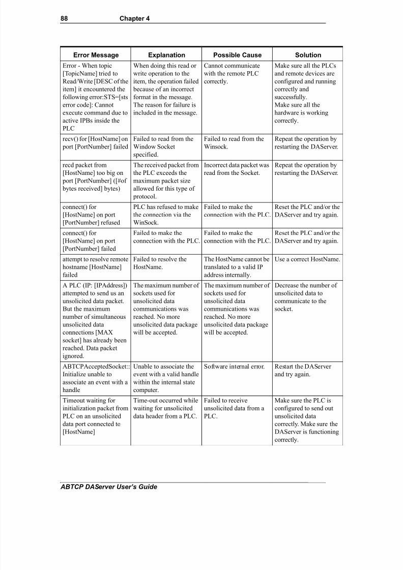
7/26/2019 Allen Bradley TCP Ethernet
http://slidepdf.com/reader/full/allen-bradley-tcp-ethernet 88/102
88 Chapter 4
ABTCP DAServer User’s Guide
Error - When topic
[TopicName] tried to
Read/Write [DESC of the
item] it encountered the
following error:STS=[stserror code]: Cannot
execute command due to
active IPBs inside the
PLC
When doing this read or
write operation to the
item, the operation failed
because of an incorrect
format in the message.The reason for failure is
included in the message.
Cannot communicate
with the remote PLC
correctly.
Make sure all the PLCs
and remote devices are
configured and running
correctly and
successfully.Make sure all the
hardware is working
correctly.
recv() for [HostName] on
port [PortNumber] failed
Failed to read from the
Window Socket
specified.
Failed to read from the
Winsock.
Repeat the operation by
restarting the DAServer.
recd packet from
[HostName] too big on
port [PortNumber] ([#of
bytes received] bytes)
The received packet from
the PLC exceeds the
maximum packet size
allowed for this type of
protocol.
Incorrect data packet was
read from the Socket.
Repeat the operation by
restarting the DAServer.
connect() for
[HostName] on port
[PortNumber] refused
PLC has refused to make
the connection via the
WinSock.
Failed to make the
connection with the PLC.
Reset the PLC and/or the
DAServer and try again.
connect() for
[HostName] on port
[PortNumber] failed
Failed to make the
connection with the PLC.
Failed to make the
connection with the PLC.
Reset the PLC and/or the
DAServer and try again.
attempt to resolve remote
hostname [HostName]
failed
Failed to resolve the
HostName.
The HostName cannot be
translated to a valid IP
address internally.
Use a correct HostName.
A PLC (IP: [IPAddress])
attempted to send us an
unsolicited data packet.But the maximum
number of simultaneous
unsolicited data
connections [MAX
socket] has already been
reached. Data packet
ignored.
The maximum number of
sockets used for
unsolicited datacommunications was
reached. No more
unsolicited data package
will be accepted.
The maximum number of
sockets used for
unsolicited datacommunications was
reached. No more
unsolicited data package
will be accepted.
Decrease the number of
unsolicited data to
communicate to thesocket.
ABTCPAcceptedSocket::
Initialize unable to
associate an event with a
handle
Unable to associate the
event with a valid handle
within the internal state
computer.
Software internal error. Restart the DAServer
and try again.
Timeout waiting forinitialization packet from
PLC on an unsolicited
data port connected to
[HostName]
Time-out occurred whilewaiting for unsolicited
data header from a PLC.
Failed to receiveunsolicited data from a
PLC.
Make sure the PLC isconfigured to send out
unsolicited data
correctly. Make sure the
DAServer is functioning
correctly.
Error Message Explanation Possible Cause Solution

7/26/2019 Allen Bradley TCP Ethernet
http://slidepdf.com/reader/full/allen-bradley-tcp-ethernet 89/102
Troubleshooting 89
ABTCP DAServer User’s Guide
PLC-5 Error Messages
The error messages generated specifically for the PLC-5 family controllers are
listed in the following table.
Timeout waiting for data
packet from PLC on an
unsolicited data port
connected to
[HostName]
Time-out occurred while
waiting for unsolicited
data packet from a PLC.
Failed to receive
unsolicited data from a
PLC.
Make sure the PLC is
configured to send out
unsolicited data
correctly. Make sure the
DAServer iscorrectlyfunctional.
Timeout waiting for an
unknown event from
PLC on an unsolicited
data port connected to
[HostName]
Time-out occurred while
waiting for unsolicited
data packet from a PLC.
Failed to receive
unsolicited data from a
PLC.
Make sure the PLC is
configured to send out
unsolicited data
correctly. Make sure the
DAServer is functioning
correctly.
An error occurred
attempting to complete
the initialization of an
unsolicited connection.
When the initialization
portion of the unsolicited
data was received, a
Winsock error occurred.
Failed to receive the
initialization portion of
the unsolicited data
packet from the PLC.
Make sure the PLC is
configured to send out
unsolicited data
correctly. Make sure the
DAServer is functioning
correctly.
An error occurred
attempting to receive the
data portion of an
unsolicited connection.
When the data portion of
the unsolicited data was
received, a Winsock
error occurred.
Failed to receive the data
portion of the unsolicited
data packet from the
PLC.
Make sure the PLC is
configured to send out
unsolicited data
correctly. Make sure the
DAServer is functioning
correctly.
Minor Error: Winsock
told us data was waiting
for us, but when we
checked it, the whole
message wasn't there.
Ignoring Winsock
Message.
Winsock error occurred;
ignore the event.
Winsock error occurred;
ignore the event.
Ignore the event and the
message.
State engine error.
Received Unsol DATA
packet, but socket was
not waiting for one.
Ignoring packet
Winsock error occurred;
ignore the event.
Winsock error occurred;
ignore the event.
Ignore the event and the
message.
Error Message Explanation Possible Cause Solution

7/26/2019 Allen Bradley TCP Ethernet
http://slidepdf.com/reader/full/allen-bradley-tcp-ethernet 90/102
90 Chapter 4
ABTCP DAServer User’s Guide
Error Message Explanation Possible Cause Solution
item <ItemName> not
valid, PLC does not have
PID feature
PID feature is not
supported for this PLC-5
configuration.
The PLC-5 configuration
indicates that the PID
feature is not supported.
Select the "Support PID"
feature option for PLC-5,
if the PLC supports the
feature.BINARY file number
must be greater than 2
Incorrect format for this
item. The Binary Item’s
File Number was smaller
than 3 for PLC-5.
The Binary Item’s File
Number must be 3 or
larger.
Only access the Binary
Item with File Number
equal to 3 or larger.
TIMER file number must
be greater than 2
Incorrect format for the
item. The Timer Item’s
File Number was smaller
than 3 for PLC-5.
The Timer Item’s File
Number must be 3 or
larger.
Only access the Timer
Item with File Number
equal to 3 or larger.
CONTROL file number
must be greater than 2
Incorrect format for the
item. The Control Item’s
File Number was smaller
than 3 for PLC-5.
The Control Item’s File
Number must be 3 or
larger.
Only access the Control
Item with File Number
equal to 3 or larger.
INTEGER file number
must be greater than 2
Incorrect format for the
item. The Integer Item’s
File Number was smaller
than 3 for PLC-5.
The Integer Item’s File
Number must be 3 or
larger.
Only access the Integer
Item with File Number
equal to 3 or larger.
BCD file number must
be greater than 2
Incorrect format for the
item. The BCD Item’s
File Number was smaller
than 3 for PLC-5.
The BCD Item’s File
Number must be 3 or
larger.
Only access the BCD
Item with File Number
equal to 3 or larger.
PD file number must be
> 8
Incorrect format for the
item. The PID Item’s File
Number was 8 or smaller
for PLC-5.
The PID Item’s File
Number must be 9 or
larger.
Only access the PID Item
with File Number equal
to 9 or larger.
ST file number must be >
8
Incorrect format for the
Item. The ST item’s File
Number was 8 or smaller
for PLC-5.
The ST Item’s File
Number must be 9 or
larger.
Only access the ST Item
with File Number equal
to 9 or larger.
BT file number must be
> 8
Incorrect format for the
Item. The BT item’s File
Number was 8 or smaller
for PLC-5.
The BT Item’s File
Number must be 9 or
larger.
Only access the BT Item
with File Number equal
to 9 or larger.
SC file number must be >
4
Incorrect format for the
Item. The SC item’s File
Number was 4 or smallerfor PLC-5.
The ST Item’s File
Number must be 5 or
larger.
Only access the ST Item
with File Number equal
to 5 or larger.
Cannot write to file
BT[FileNumber]
Failed to write to a BT
item for PLC-5.
For PLC-5, write
operation to a BT item is
not permitted.
Do not attempt to write
to a BT item for PLC-5.

7/26/2019 Allen Bradley TCP Ethernet
http://slidepdf.com/reader/full/allen-bradley-tcp-ethernet 91/102
Troubleshooting 91
ABTCP DAServer User’s Guide
SLC 500 Error Messages
The following table lists all the SLC-500-controller-specific error messages.
PLC-5/250 Error Messages
The error messages generated specifically for the PLC-5/250 controllers are
listed in the following table.
Error Message Explanation Possible Cause Solution
BINARY file number
must be 3 or 9-255
Incorrect format for this
item. The Binary Item’s
File Number was not 3 or
9-255 for SLC 500.
Binary Item’s File
Number must be 3 or 9-
255.
Only access Binary Item
with valid File Number.
TIMER file number must
be 4 or 9-255
Incorrect format for the
item. The Timer Item’s
File Number was not 4 or
9-255 for SLC 500.
Timer Item’s File
Number must be 4 or 9-
255.
Only access Timer Item
with valid File Number.
COUNTER file number
must be greater than 5 or
9-255
Incorrect format for the
item. The Counter Item’s
File Number was not 5 or
9-255 for SLC 500.
Counter Item’s File
Number must be 5 or 9-
255.
Only access Counter
Item with valid File
Number.
CONTROL file number
must be greater than 6 or
9-255
Incorrect format for the
item. The Control Item’s
File Numberwas not 6 or
9-255 for SLC 500.
The Control Item’s File
Number must be 6 or 9-
255.
Only access the Control
Item with the valid File
Number.
INTEGER file number
must be 7 or 9-255
Incorrect format for the
item. The Integer Item’s
File Number was not 7 or
9-255 for SLC 500.
The Integer Item’s File
Number must be 7 or 9-
255.
Only access the Integer
Item with the valid File
Number.
FLOAT file number must
be 8 or 8-255
Incorrect format for the
item. The Float Item’s
File Number was not 8 or
8-255 for SLC 500.
The Float Item’s File
Number must be 8 or 8-
255.
Only access the Float
Item with the valid File
Number.
Error Message Explanation Possible Cause Solution
File numbers must be
between 0 and 9999
Incorrect format for the
Item. The Item’s File
Number was out of rangefor PLC-5/250.
A bad Item’s File
Number was used.
Use the valid range for
the Item’s File Number.
Unsupported section type
[File Type]
Incorrect format for the
item. An invalid Item
Type for PL5/250 was
used.
There is no such Item
Type name for PLC-
5/250.
Use the valid Item Type
for PLC-5/250.

7/26/2019 Allen Bradley TCP Ethernet
http://slidepdf.com/reader/full/allen-bradley-tcp-ethernet 92/102
92 Chapter 4
ABTCP DAServer User’s Guide
PLC-5 and SLC 500 Error Messages
The error messages listed in the following table pertain to both the PLC-5 and
SLC 500 controllers.
PLC-5, SLC 500, and PLC-5/250 Error Messages
The following table lists error messages generated specifically for the PLC-5,
SLC 500, and PLC-5/250 families of controllers.
Error Message Explanation Possible Cause Solution
File numbers must be
between 0 and 999
For PLC-5 and SLC 500:
Incorrect format for the
Item. The Item’s File
Number was out of
range.
A bad item File Number
was used.
Use a valid range for the
Item’s File Number.
OUTPUT file number
must be 0
For PLC-5 and SLC 500:
Incorrect format for the
item. The Output Item’s
File Number was not 0.
The Output Item’s File
Number must be 0.
Only access the Output
Item with a File Number
equaling to 0.
INPUT file number must
be 1
For PLC-5 and SLC 500:
Incorrect format for the
item. The Input Item’s
File Number was not 1.
The Input Item’s File
Number must be 1.
Only access the Input
Item with a File Number
that equals to 1.
STATUS file number
must be 2
For PLC-5 and SLC 500:
Incorrect format for the
item. The Status Item’s
File Number was not 2.
The Status Item’s File
Number must be 2.
Only access the Status
Item with a File Number
equaling to 2.
FLOATING POINT file
number must be greater
than 2
For PLC-5 and SLC 500:
Incorrect format for the
item. The Floating Point
Item’s File Number was
smaller than 3.
The Floating Point Item’s
File Number must be 3 or
larger.
Only access the Floating
Point Item with a File
Number that equals to 3
or larger.
FLOATING POINT filecannot have bit number
For PLC-5 and SLC 500:Incorrect format for the
item. The Floating Point
Item contained a bit
number field.
The Floating Point Itemmust not contain a bit
number field.
Only access the FloatingPoint Item without a bit
number field.
ASCII file number must
be greater than 2
For PLC-5 and SLC 500:
Incorrect format for the
item. The ASCII Item’s
File Number was smaller
than 3.
The ASCII Item’s File
Number must be 3 or
larger.
Only access the ASCII
Item with a File Number
equaling to 3 or larger.

7/26/2019 Allen Bradley TCP Ethernet
http://slidepdf.com/reader/full/allen-bradley-tcp-ethernet 93/102
Troubleshooting 93
ABTCP DAServer User’s Guide
Error Message Explanation Possible Cause Solution
BINARY file, bit>15 and
element>0
For PLC-5, SLC 500,
and PLC-5/250:
Incorrect format for the
item. The Binary Itemcontained an element
number, but its bit
number was larger than
15.
For PLC-5, SLC 500, and
PLC-5/250: The valid
format for a PLC-5 Binary
Item is: B[FileNumber]:[Element]/[Bit], where Bit
is from 0 to 15.
In this case, the Bit field
was larger than 15.
Only access the Binary
Item with the valid
range.
Unsupported file type
[File Type]
For PLC-5, SLC 500,
and PLC-5/250:
Incorrect format for the
item. An invalid Item
Type was used.
There was no such Item
Type name.
Use the valid Item
Type.
[Sub-Element] not valid
for type [FileType] files.
For PLC-5, SLC 500,
and PLC-5/250:
Incorrect format for theitem. The Sub-Element is
not valid for this File
Type.
Wrong Item format with a
wrong Sub-Element type.
Only access the valid
item format with the
correct Sub-Elementtype.
[Sub-Element not valid
for type [FileType]
section.
For PLC-5, SLC 500,
and PLC-5/250:
Incorrect format for the
item. The Sub-Element is
not valid for this section.
Wrong Item format. Use only the valid item
format.
Attempt to write read
only item in file
[FileNumber] element
[Element#] subelement[Sub-Element#] ignored
For PLC-5, SLC-500,
and PLC-5/250: Write
operation failed due to an
attempt to write to aread-only item.
An attempt to write to a
read-only item caused the
failure.
Do not attempt a write
operation to a read-only
item.

7/26/2019 Allen Bradley TCP Ethernet
http://slidepdf.com/reader/full/allen-bradley-tcp-ethernet 94/102
94 Chapter 4
ABTCP DAServer User’s Guide

7/26/2019 Allen Bradley TCP Ethernet
http://slidepdf.com/reader/full/allen-bradley-tcp-ethernet 95/102
Reference 95
ABTCP DAServer User’s Guide
C H A P T E R 5
Reference
Contents
• DAServer Architecture
• Component Environments
DAServer ArchitectureNote DAServers are supported on Microsoft Windows 2003, Windows 2000,
and Windows XP only. NetDDE protocol is not supported by DAServers.
This DAServer is a collection of components that work in concert to provide
communications access with the hardware field devices. These components
include:
• DAServer Manager: This is the Microsoft Management Console (MMC)
snap-in, which is part of the ArchestrA SMC suite of utilities supplied
with the DAServer, that provides the necessary user interface for
diagnostics, configuration, and activation.
• Client Plug-ins: These are the components that are added to a DAServer
to enable communications with clients. Examples are: OPC,
DDE/Suitelink, and so on.
• DAS Engine: This is the library that contains all the common logic to
drive data access.
• Device Protocol: This is the custom code provided by this DAServer to
define the communications with a particular device.
DAServers
A DAServer is comprised of three physical parts (see the following figure).
They are the following:
• Plug-in Component(s): Responsible for communicating with clients.
• DAS Engine: This common component is used by all DAServers.
• PLC Protocol Layer; DAServer-specific: Responsible for
communicating with the hardware.

7/26/2019 Allen Bradley TCP Ethernet
http://slidepdf.com/reader/full/allen-bradley-tcp-ethernet 96/102
96 Chapter 5
ABTCP DAServer User’s Guide
DAServer Architecture
Each physical part of a DAServer is comprised of a set of .exe and/or .dll
modules. Wonderware provides the Plug-ins and the DAS Engine. The DAS
Toolkit user creates the PLC Protocol Layer (DAServer-specific) modules. All
three sets of modules are required for a fully functioning DAServer.
Plug-ins
Plug-ins provide a protocol translation function for device integration clients.
Typical Plug-ins communicate in DDE, SuiteLink, or OPC protocol, and serve
as interfaces between their clients and the DAS Engine.
Note Items of an array are not supported in the DDE/SL plug-in. These arrays
are converted to HEXASCII strings, which provide legacy behavior for
DAServers that support this in the DAServer-specific code.
DAS Engine
The DAS Engine is a middleware component that exposes two sets of unique
interfaces:

7/26/2019 Allen Bradley TCP Ethernet
http://slidepdf.com/reader/full/allen-bradley-tcp-ethernet 97/102
Reference 97
ABTCP DAServer User’s Guide
• One for communicating with Plug-ins.
• The other one for communicating with the PLC Protocol Layer
components.
PLC Protocol Layer
The PLC Protocol Layer provides a protocol translation function for specifichardware such as ModBus, and serves as an interface between the DAS Engine
and the hardware.
Component Environments
Stand-alone DAServers have the following characteristics:
• The DAS Engine is dynamically linked to the other DAServer
components. In other words, a new DAS Engine (feature enhancement or
bug fix) would not require relinking to the other components nor re-QA of
those other components. When deployed to the system, the new DAS
Engine would attach to all existing DAServer components.
• Newly deployed Plug-ins (feature enhancements or bug fixes) do not
require relinking nor re-QA of associated components. Even new Plug-ins
(for example, OPC Alarm & Events) would not require any development
changes to the other components, and therefore no relinking in a customer-
installed base. In fact, it is feasible to implement new functionality in a
Plug-in to enhance the DAServer without involvement of the code of the
other components.
• DAServers can be configured in one stand-alone configuration utility
(DAServer Manager), capable of displaying specific configuration pages
for all DAServers. This utility allows browsing and editing of DAServers
on different nodes.
• The DAServer Manager diagnostics tool displays generic diagnostic
objects common to all DAServers, in addition to the DAServer-specific/
DAServer developer-defined diagnostic data.
The DAServer data configuration format is XML. Any XML-enabled program
(for example, XML Editor) can read this format.

7/26/2019 Allen Bradley TCP Ethernet
http://slidepdf.com/reader/full/allen-bradley-tcp-ethernet 98/102
98 Chapter 5
ABTCP DAServer User’s Guide

7/26/2019 Allen Bradley TCP Ethernet
http://slidepdf.com/reader/full/allen-bradley-tcp-ethernet 99/102
99
ABTCP DAServer User’s Guide
Index
Symbols
$SYS$ActiveItemCount 68$SYS$ErrorCode 66
$SYS$ErrorCount 68$SYS$ErrorText 66$SYS$ItemCount 68$SYS$Licensed 65$SYS$MaxInterval 67$SYS$PollNow 68$SYS$ReadComplete 68$SYS$Status 65$SYS$StoreSettings 66$SYS$UpdateInterval 67$SYS$WriteComplete 67.csv file 30.csv file in Excel 32
A
ABTCP hierarchy 15, 20Access Path 69Access the settings for device groups 36Activate Server 17Actual PLC item names 30Add command 30Add item references 31Add PLC5_TCPIP Object 22Add PORT_TCPIP Object 21Add PYRAMID_EI Object 25Add PYRAMID_PLC5250 Object 26Add SLC500_TCPIP Object 23Alias names 30Aliases 29application name 12ArchestrA SMC 95ArchestrA System Management Console 9, 16, 18ArchestrA.DASABTCP.1 12, 16, 17, 19Archive 37Archive Configuration Set 37arrays 96
B
Before 7Boolean item 13
C
Clear All command 32, 34
Clear all device items 32Client Messaging 36Client Plug-ins 95Communication protocols 10Config Default Update Interval 29Configuration 16, 36Configuration node 37Configuration set 29, 32Configuration Set Name 37Configure As Service 17, 20Configure default update intervals 29
Connection timeout 23, 24, 26Create or add device groups 28Create or add device items 30CSV file 32
D
DAS Engine 63, 95DAS Toolkit 96DAServer architecture 13DAServer Manager 12, 18, 19, 95DAServer Manager book 20DAServer Manager documentation 17, 18, 20DAServer Manager Online Help 16, 19DAServer Manager tree 16DAServer version 71Data block size 23, 24, 27DCOM 10DDE 11Default update interval 29Delete a device item from the list 31Delete command 31Delete device groups 29Device group 64device group 12Device Groups 15, 17, 20, 69Device Groups dialog box 28Device Groups tab 27, 28, 36Device groups. 37Device hierarchy 15, 19Device Item Definitions 29Device Items 17, 20Device items 37Device Items box 34Device Items dialog box 29, 30, 32, 33, 34
Device Items Name list 30Device Items tab 29, 30Device nodes 37Device Protocol 95Diagnostics 10Distributed COM 10Dynamic Data Exchange 10
E
Edit mode 20Edit update intervals 29Ethernet adapter 18Ethernet Interface Module 9Ethernet network 9
Excel macro 73Export command 32Export DAServer device item data 32Export DAServer device item data to a CSV file 32Export feature 32
F
FastDDE 10Features 10, 13

7/26/2019 Allen Bradley TCP Ethernet
http://slidepdf.com/reader/full/allen-bradley-tcp-ethernet 100/102
100 Index
ABTCP DAServer User’s Guide
G
Global Configuration parameters 37Group 64group name 12
H
Help menu 20HEXASCII strings 96Hierarchical location 64Hierarchy 21HMI 10Host Name 22Host name 24, 25Host Names 18Hot configurable 37
I
import 33Import command 33, 34Import DAServer device item data 32
Import DAServer device item data from a CSVfile 33Import feature 32Import off-line-edited DAServer device item datafrom a CSV file 34Internet Protocol 11IP-address-to-IP-address communications 36Item ID 69Item Name 69item name 12Item Reference column 30, 31, 33ItemID 11
L
Large-scale edit on item data 32License Manager 13Link name 12, 69Log Flag data 74Log Viewer documentation 74Logger 38
M
Make edits on device groups 28Manual or automatic service 17, 20Maximum outstanding messages 21Microsoft Excel manual 73Microsoft Management Console 9, 18, 95Middleware component 96MMC 9, 18, 95
ModBus 97
N
Name column 29, 30, 33 NetDDE 11 Network transport protocol 10 New_ Pyramid_EI_000 Parameters 25 New_PLC_000 Parameters 28, 29 New_PLC5_TCPIP_000 Parameters 22
New_PLC5_TCPIP_000.csv 32 New_PYRAMID_PLC5250_000 Parameters 26 New_SLC500_TCPIP_000 Parameters 24 Nmae column 30node name 11, 12
O
Off-line edit on item data 32OLE for Process Control 10OLE/COM technology 10OPC 10OPC client 9, 30OPC Group 69OPC Item browsing 30OPC Item name 11Open button 33Optimization mode 20
P
Peer-to-Peer 36Peer-to-peer unsolicited messaging 36
PLC configuration 32PLC disconnect 72PLC hierarchy node 30, 34PLC Hierarchyname.csv 32PLC Protocol Layer 95PLC5_TCPIP Object 16, 22Plug-in Component 95Poke Mode settings 20Port type 21PORT_TCPIP 16ProgID 12
program name 12Pyramid EI integrator module 9Pyramid Integrator 9PYRAMID_EI Object 16, 22PYRAMID_PLC5250 Object 17
R
Receive unsolicited messages 36reference 95Remote Reference formulas for cells 73, 74Rename a device item from the list 31Rename command 31Reply time-out 72Reply timeout 23, 25, 27
S
SCADA 10Scan-based Message Handling 35
Service 17, 20Setup.exe 16SLC500_TCPIP Object 16, 22Slow poll mode 72SMC 9, 15, 18Snap-in environment 16, 19SuiteLink 9, 10Supports PID and string files 23Supports unsolicited ‘CLIENT’ messaging 23, 27System Management Console 15, 16, 19

7/26/2019 Allen Bradley TCP Ethernet
http://slidepdf.com/reader/full/allen-bradley-tcp-ethernet 101/102
101
ABTCP DAServer User’s Guide
T
Target PLC 69TCP/IP bus protocol 10TCP/IP software 18The file can be edited off-line 33To add the PYRAMID_PLC5250 object to yourABTCP hierarchy 26To archive configuration sets 37To install the DAServer 18To install the Ethernet adapter 18To prepare the ABTCP DAServer 16topic name 12Transmission Control Protocol 11
U
UNIX 11Unsolicited Message Handling 35Update Interval 35, 36Update Interval column 29Use different configuration sets 37
VValue Time Quality (VTQ) 10VMS 11
W
WinSock 10WinSock interface 9Wonderware folder 16Wonderware InTouch 9
X
XML 97
XML Editor 97

7/26/2019 Allen Bradley TCP Ethernet
http://slidepdf.com/reader/full/allen-bradley-tcp-ethernet 102/102
102 Index