Embed Size (px)
Citation preview
Installation, Operation and Maintenance
Manual for the Following Equipment:
All HD Series Lifts
This manual contains specific information for your equipment, see options on P 2-1.
In any correspondence with your distributor you will need the following information:
Model Number______________________ Serial Number_____________________________ Installation location: __________________________________ __________________________________ __________________________________
CAUTION! At Initial Installation, determine proper motor/pump rotation by starting the motor in very short intervals to prevent permanent pump damage. Running the pump backwards will
damage it. See the Installation Instructions, Section 4, for proper procedure. Distributor Information: ______________________________
_______________________________ _______________________________ _______________________________
Advance Lifts, Inc. 701 Kirk Road St. Charles, IL 60174-3428 Toll Free 1-800-843-3625 Sales Fax 1-630-584-9405 Parts and Service Fax 1-630-584-6837 E-mail: [email protected] *Advance Lifts, Inc. furnishes one manual with each unit. Additional manuals are available at
$25.00 each.
P 1-1
SECTION 2. INDEX & INTRODUCTION
Identification Sheet…………………………………………………………. Section 1 Index & Introduction………………………………………………………… Section 2 *Responsibilities Of Owners/ Users……………………………………….. Section 3 *Installation Instructions…………………………………………………….. Section 4 *Operation Instructions……………………………………………………… Section 5 *Maintenance Instructions……………………………………………….. … Section 6 *Safety Bar Placement Warning Label Specifications & Locations ………………………………. Section 7 Hydraulic Details…………………………………………………………….. Section 8
General hydraulic information Oil recommendation & seal compatibility
HD Series power unit photograph Hydraulic schematic Hydraulic component list HD Series cylinder photograph (piston style) HD Series cylinder drawing and parts list Cylinder repair procedures Electrical Details…………………………………………………………….. Section 9 General electrical information Typical controller photograph Electrical schematic Wire size recommendations Troubleshooting Hints………………………………………………………. Section 10 Warranty……………………………………………………………………… Section 11 Attachments: Material Safety Data Sheets & Parts List………………… Section 12 Optional Accessory Information (Only included when appropriate) Wheel & dolly: Photo and drawing Transport casters: Photo and drawing Manual turntable: Photo and drawing Powered turntable: Photo, drawing and schematics Bellows: Photo and drawing Tilter: Photo, drawing and schematics External power unit: Photo and schematics Continuous running power unit: Photo and schematics *Mandatory reading before attempting installation.
P 2-1

SECTION 2. (CONTINUED) INTRODUCTION
Congratulations, the equipment that you have purchased is of the highest quality available. Your Advance Lift will provide you with many years of trouble free service in return for the minimal maintenance described in this manual. Please be sure that no individual is allowed to operate the lift until they have been fully familiarized with the operating instructions in this manual. Also, insure that at least one person at the lift site is familiar with the maintenance section of this manual and is assigned responsibility for doing the maintenance on a regular basis. Please note that the lift has a metal nameplate attached to it that contains information such as the model number, capacities, and serial number. Do not remove the nameplate. Be sure that no operator ever exceeds the capacities shown on the nameplate or they may cause damage to the lift or injure personnel. Also, be sure to have the serial number of the lift handy if you have to call your distributor. That number identifies your specific lift and will allow your distributors personnel to give you the most thorough and timely assistance possible. This manual is under constant review and we would appreciate any constructive suggestions that may enhance its usefulness. Please send your suggestions to Advance lifts, Inc. Attn: Engineering Dept. Thank you for purchasing our product.
P 2-2
SECTION 3. RESPONSIBILITIES OF OWNERS & USERS
Inspection and Maintenance: The lift shall be inspected and maintained in proper working order in accordance with this manual and safe operating practices. Removal from Service: Any lift not in safe operating condition shall be removed from service until it is repaired to the original manufacturer’s standards. Repairs: Authorized personnel in conformance with the manufacturer’s instructions shall make all repairs. Operators: Only trained and authorized personnel shall be permitted to operate the lift. They must understand to be alert to safety hazards during all operations. Before Operation: Before using the lift, the operator shall have: 1. Read and understood the manufacturer’s operating instructions and safety rules, or
been trained by a qualified person. 2. Inspected the lift for proper operation and condition. Any suspect item shall be
carefully examined and a determination made by a qualified person as to whether it constitutes a safety hazard. All unsafe items shall be corrected before further use of the lift.
During Operations: The lift shall be used only in accordance with its intended use and within the manufacturer’s limitation and safety rules: 1. Do not overload the lift. 2. Insure that all safety devices are operational and in place. 3. Be certain that all loads are centered on the lift. 4. Insure that all personnel near operating lifts understand to stand back from operating
lifts so that no body parts can be pinched by the mechanism or platform and any items that may fall off the lift will not strike them.
Modifications Or Alterations: Modifications or alteration of industrial scissors lifts shall be made in conformance with all applicable provisions of scissors lift manufacturer’s proposed ANSI standards and shall be at least as safe as the equipment was before modification. These changes shall also satisfy recommendations of the original equipment manufacturer for the particular application of the lift.
P 3-1

SECTION 4. INSTALLATION INSTRUCTIONS
Floor mounted units with base frames:
1. Move the lift to the usage area; insuring the floor is clean and level. If slings are used, encircle the entire lift, not just the platform.
2. If floor is not level, shim each corner of the base frame to level the unit. Caution!
Before securing the unit to the floor, shim or grout the entire base frame assembly. The base frame must be completely supported.
3. Using the pushbutton control or footswitch, push the “up” button in short jogs to see
if the lift will rise. If the unit does not rise, check the motor rotation. On 3 phase systems, 2 of the 3 power leads may have to be switched so the pump will turn in the proper direction. Caution! Operating a hydraulic pump in reverse, even for brief periods, can cause permanent pump damage.
4. Raise the lift halfway several times then fully lower it, holding the down control an
extra 10 seconds each time the lift is lowered to bleed air from the unit. HD units should be filled within 2” of the top of the reservoir with the unit in the fully lowered position.
5. Due to the rigors of shipping it may be necessary to snug up some hydraulic fittings.
Hose fittings, in particular, are most susceptible. 6. Clean up any debris or spilled fluid as they may later be misinterpreted as
mechanical trouble or a cylinder leak. Remove maintenance bars and lower the unit. 7. Instruct user(s) in the proper operation of the lift, safety precautions, and equipment
capacity. Supply maintenance personnel with this service manual. Pit mounted units: 1. Check all pit dimensions for accuracy.
2. Attach a temporary electrical line through the pit conduit to the lift. Check for correct motor rotation; (see paragraph #3 in “floor mounted installation”).
3. Using slings, encircle the entire lift, not just the platform and lower the lift into the pit, centering it for 1” minimum clearance on all sides to the pit wall.
4. Raise the lift with the pushbutton or footswitch and remove the slings. Run the unit up and down several times. Level and center the lift by shimming and grouting the entire base frame. (Continuous base frame support is essential for proper installation). Lag the unit in place using ½” x 5”, “Rawl-Studs” or wedge anchors in the holes provided.
5. With the lift fully elevated shutoff the main power, then complete the permanent electrical wiring.
6. Follow the instructions outlined in paragraphs 4, 5 and 6 under “Floor mounted installation”. To complete the installation.
P 4-1
CAUTION! Continuous baseframe support is essential for proper installation.
SECTION 5. OPERATING INSTRUCTIONS
Hydraulic scissors lifts have an excellent safety record overall, but as with all moving equipment, they can be dangerous. Operators must use common sense and take responsibility for the safety of everyone near the lift. They must use the safety devices provided and be careful not to surprise anyone in the area with the movement of the lift.
Pre-operational checks: 1. Check all electrical wiring and connections to be sure that they are completed
properly and are operational.
2. Check for obstructions or debris that may interfere with the safe operations of the lift.
3. Be sure that all personnel in the area are a safe distance away from the lift and aware that you are about to operate it.
4. If there are any optional safety devices such as bellows or electric toe guards, check them for proper operation.
Test operating the equipment: 1. Station yourself so that you will always see the equipment when it is in operation.
Never operate the equipment blind!
2. Raise the equipment and note that the control is a constant pressure, “dead-man” type. When you release the up or down switch the unit should stop moving immediately and maintain its elevation. If it does not, contact your maintenance personnel.
3. Cycle the equipment several times to be sure that it is operating smoothly with no jerking or sudden movement. On initial start up there may be some air in the lines or the cylinders may be dry due to storage so it my take several cycles to smooth out the operation. If the operation is not smooth after several cycles, contact your maintenance personnel. Any evidence of binding or scraping in the operation should cause you to immediately stop using the lift.
4. Check all safety devices for proper operation.
5. If you elect to test load the equipment, be sure that you do not exceed the capacities shown on the nameplate. Overloading may cause structural stresses that may not show up for some time, but will diminish the life and capacity of the unit. If you have any questions about testing the unit, call our customer service department at 1-800-843-3625.
Daily operation:
1. All personnel should be required to read the entire operating instruction section of this manual prior to operating the lift.
2. Operators must know the capacity of the unit and be aware of any loads that may exceed the capacity.
3. WARNING! Operators must be alert to all personnel in the vicinity of the lift and avoid any surprises to these personnel in regard to movement of or the position of the lift at any time. Never operate unit if you cannot see it and the personnel around it.
P 5-1
SECTION 5. (CONTINUED) OPERATING INSTRUCTIONS
Daily operation (continued):
4. On the first use of the lift each day, the operator should check to see that the lift is functioning properly and smoothly. All safety devices should be in place and operating correctly.
5. If the unit has a traveling electrical cord, the operator must insure that it is kept away
from the lift as it raises and lowers.
Warning! Loads should be centered before raising or lowering the lift as this will help insure even wear on all moving parts.
General Information Notes:
1. A special additive has been added to the hydraulic fluid to facilitate the initial break-in period for the tight tolerance, high quality, hydraulic cylinders. If the original fluid is changed, contact the factory for purchasing replacement fluid.
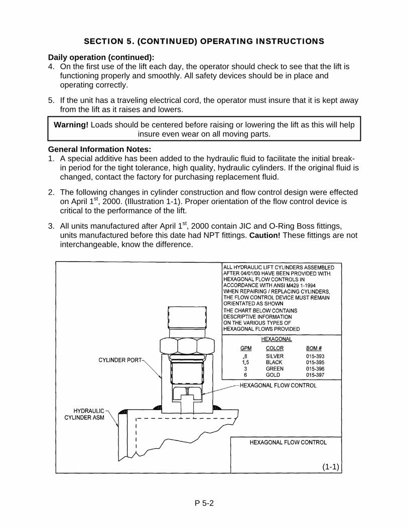
2. The following changes in cylinder construction and flow control design were effected
on April 1st, 2000. (Illustration 1-1). Proper orientation of the flow control device is critical to the performance of the lift.
3. All units manufactured after April 1st, 2000 contain JIC and O-Ring Boss fittings,
units manufactured before this date had NPT fittings. Caution! These fittings are not interchangeable, know the difference.
P 5-2
(1-1)

SECTION 6. MAINTENANCE INSTRUCTIONS
1. Always remember that this is machinery with large moving parts that can seriously
hurt you. 2. Read and understand this manual before attempting any service work. 3. WARNING! Always use the safety bars or safety leg when you are going to work on
the unit in the elevated position or must reach under the platform. (See photo on page 6-4 for proper positioning and engagement of the safety bars).
4. When using the safety bars, adhere to the following rules:
A. The unit must be unloaded. B. Be sure the safety bars are properly engaged. C. Hold the down pedal or pushbutton an extra 10 seconds when lowering onto the
safety bars to be sure that all the weight of the lift is on the bars. D. Disconnect and tag the electricity to the unit to prevent accidental movement of
the lift by other personnel. E. Spend as little time as possible under the lift.
5. Use only replacement parts recommended by the manufacturer. 6. Do not let the equipment stay in disrepair; fix small problems before they become big
problems. A unit in disrepair can become a severe hazard if left unattended. 7. Inspect the equipment on a regular schedule, preferably monthly. 8. Never work on the hydraulics or electrical systems unless the unit is fully lowered or
properly sitting on the safety support or wheel block. 9. Never apply a load to the equipment until the base frame is continuously supported. 10. WARNING! Never expect to hold the leg assemblies open by simply lifting one end
of a platform. A. The roller end of most lifts is not “gibbed” or captured in any way, so lifting on the
roller end will simply tilt the platform. B. Even if you raise the clevis end of the platform, if the base frame is not firmly
lagged to the ground or held down by some other means, the legs will come up with the platform in an unpredictable manner and could cause personal injury.
C. The only safe way to hold a lift’s legs open is to use the factory designed safety support. If a safety maintenance bar is
Routine Maintenance: (All lifts) Weekly: Once a week or after repetitive operation, the unit should be raise to its full height. This will get rid of cylinder oil seepage buildup and lubricate the upper cylinder barrel. Monthly: 1. Check the hydraulic fluid level as specified in Section 4, Paragraph 4. WARNING! Be sure a maintenance safety leg or safety bars are properly engaged before performing maintenance checks 2 through 6 or reaching beneath a raised lift. (See instructions 3, 4 and 10 above)
P 6-1

SECTION 6. (CONTINUED) MAINTENANCE INSTRUCTIONS
2. Clean all debris from the vicinity of floor or pit mounted units in order to avoid
interference with the lift mechanism or rollers. 3. Check for presence and proper seating of all snap rings and clips on all axles,
cylinder, and rollers. 4. Check rollers, pins and bushings for any signs of wear such as flat spots, missing
fasteners, or dislodged bearing material. 5. Check the hydraulic fittings for cracks or leaks and clean up any weepage on or
beneath the cylinder. 6. Check hoses and electrical lines for abrasions or other abuse and check for snug
connections. 7. Operate the unit and check for any abnormal noise or vibrations. 8. Check all safety devices on the unit such as the condition of the pleated bellows or
smooth operation of the electric toe guards. Seasonal or Semiannual Maintenance: Change hydraulic fluid for ambient temperature change if appropriate or if there is any evidence of accumulated condensation creating water contamination. See page P 5-2, paragraph number 1, under the heading “General Information Notes” and P 4-1, paragraph number 4 for more information on changing fluid.
P 6-2
Recommended Lift Blocking Procedures
WARNING! Only authorized personnel should perform inspection or maintenance and service procedures. Unauthorized personnel attempting these procedures do so at the risk of severe injury or death.
DANGER! Failure to properly adhere to lift blocking procedures is to risk the sudden and uncontrolled descent of the lift during maintenance or inspection. A falling lift can cause severe injury or death.
This procedure describes the only factory-approved method of working under a lift. Follow these instructions EVERY time you plan to reach or crawl beneath the lift to perform service or maintenance – no matter how momentary that might be.
If the factory-provided maintenance device is damaged or missing, stop immediately and consult the factory for assistance. The manufacturer is not liable for your failure to use the approved maintenance device(s) and procedures that have been provided.
1. Any load must be removed from the lift prior to engaging the maintenance device(s). These devices are designed to support an unloaded lift only. Failure to remove the load from the lift prior to blocking could cause the failure of the maintenance device(s) and allow the lift to fall unexpectedly. This can result in personal injury or death, or permanent damage to the maintenance device(s) and/or the lift.
2. Raise the lift to its fully raised position. If you do not, the maintenance device(s) may not be able to be placed properly in its/their designed blocking position.
3. Remove the maintenance device(s) from its/their storage location and place it/them into the engaged position as shown in Figure 1-1 (Note: further information may be useful here to provide additional instructions as to the location and method of storage and engaged positions).
4. Lower the lift until it makes complete contact with the maintenance device(s). Re-check to ensure that all provided devices are fully and securely engaged. If the device(s) is/are not fully engaged the lift could fall unexpectedly, resulting in permanent damage to the device(s) or the lift.
DANGER!
If for any reason you are unable to lower the lift completely onto the maintenance device(s), stop immediately and consult the factory. Failure to properly use the factory approved maintenance device(s) could result in severe injury or death.
5. (For single-acting hydraulic, and pneumatic lifts) Once the maintenance device(s)
is/are properly and securely engaged, continue to press the down button, valve or switch for an additional 5-10 seconds to relieve all pressure in the operating system.
P 6-3

Recommended Lift Blocking Procedures (Continued)
WARNING! Failure to relieve operating system pressure could result in the sudden and unexpected release of high-pressure fluids (or air) during maintenance and/or repair of the lift and result in severe injury or death.
6. Follow OSHA electrical lock-out/tag-out procedures. Disconnect and tag all
electrical and/or other power sources to prevent an unplanned or unexpected actuation of the lift.
7. Once inspection or work is complete, reverse the performance of the steps above to raise the lift off the maintenance device(s) and place the device(s) back into its/their designated storage position(s).
DANGER HIGH VOLTAGE! Disconnect and/or lock out the electrical supply to the power unit prior to any installation or maintenance being performed.
1. Maintenance bars should be stored near the lift in a convenient location. 2. Raise the lift to full travel, and place the safety bar in front of each roller wheel on the
scissors leg. Make sure the safety bar angle captures the base frame angle (see photo 1-1).
3. Once both safety bars are in place, slowly lower the lift until the roller wheel is engaged with the safety bars and the safety bars rest against the end of the base frame. Visually inspect both safety bars to insure they are secure.
4. To disengage the safety bars raise the lift to move the roller wheels off the safety bars and make sure lift operates correctly. If assistance is required in removal of the safety bar, lightly tap with a hammer to break it loose.
Maintenance Bar in Use
P 6-4
(Figure 1-1)
Safety Bar Angle
Roller Wheel
Maintenance Bar
Baseframe Angle
SECTION 7. WARNING LABEL SPECIFICATIONS & LOCATIONS
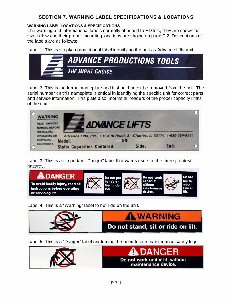
WARNING LABEL LOCATIONS & SPECIFICATIONS The warning and informational labels normally attached to HD lifts, they are shown full size below and their proper mounting locations are shown on page 7-2. Descriptions of the labels are as follows: Label 1: This is simply a promotional label identifying the unit as Advance Lifts unit.
Label 2: This is the formal nameplate and it should never be removed from the unit. The serial number on this nameplate is critical in identifying the specific unit for correct parts and service information. This plate also informs all readers of the proper capacity limits of the unit.
Label 3: This is an important “Danger” label that warns users of the three greatest hazards.
Label 4: This is a “Warning” label to not ride on the unit.
Label 5: This is a “Danger” label reinforcing the need to use maintenance safety legs.
P 7-1
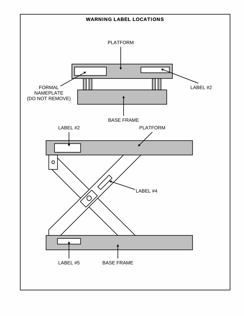
BASE FRAME
LABEL #2 FORMAL NAMEPLATE
(DO NOT REMOVE)
PLATFORM
LABEL #2 PLATFORM
LABEL #4
LABEL #5 BASE FRAME
WARNING LABEL LOCATIONS
SECTION 8. HYDRAULIC DETAILS 1. Weepage and Leakage:
A. All hydraulic cylinders will require the replacement of packing’s and seals after a period of time depending on usage and environmental conditions. It is considered normal maintenance. However maintenance personnel should recognize the difference between leakage and weepage.
B. Weepage is the normal accumulation of fluid that passes the seals in the course of operations, as the hydraulic fluid properly performs its lubrication function on cylinder walls and piston rods. It may be occasionally observed squirting from cylinder breathers, but should stop squirting after several cycles of full stroke when the small accumulation is cleared.
C. Leakage is the fluid, which leaks past worn or cut packing’s and seals. It too may be observed squirting, but does not stop after several cycles and the lift will probably not hold position under load.
D. See “Repacking” under cylinder repair procedures in Section 8, page 8-7. E. Always be careful when working around cylinders, not to nick the extended rod or
dent the cylinder casing, as this may cause damage to cylinder seals or packing’s.
F. If you elect to repaint or retouch any part of the lift, cover exposed rods with plastic or soluble grease, which can be removed after painting to insure that no paint sticks to the rods and damages packing’s or seals.
2. General precautions: A. Caution: Be sure that all pressure is relieved from the hydraulic system before
disassembling any components. Continue to hold the “down” control for several seconds after fully lowering the unit on its safety support or the ground, before opening a line or component.
B. Always be careful to avoid contamination entering the system. Be especially careful with the ends of hoses, which may fall into oil dry, or dirt. If you suspect contamination, flush the system and components.
3. Hydraulic fittings, sealant and torque’s: A. Advance Lifts may be equipped with either NPT fittings (tapered), or SAE fittings
(with O-ring seals), or JIC fittings (37-1/2˚ tapered). Know the difference. B. Be careful when tightening NPT fittings not to over-tighten and crack them.
Swivel fittings are especially vulnerable and should only be tightened enough to stop leaking.
C. If leakage persists after tightening the fittings fairly hard, inspect fittings for burrs on the mating edges or the possibility of a 37-1/2˚ SAE fitting being mixed with 30˚ NPT fittings or either one being mixed with SAE 45˚ fittings.
D. When using Teflon tape on NPT fittings, be sure the tape is started 1-1/2 threads back from the leading edge and only use 2 wraps to be sure that tape does not break off and contaminate the system. You may substitute pipe sealant with Teflon paste from Pro Lock or Locktite, again don’t over apply. Never use sealant or tapes on JIC, O-Ring Boss or swivel fittings.
E. Be extremely careful not to over-tighten ORB fittings, thread the fitting finger tight and then tighten the nut on the fitting.
F. Never reuse old Teflon tape. Once a connection has been opened, remove all tape and apply fresh tape.
P 8-1
OIL RECOMMENDATIONS AND SEAL COMPATIBILITY
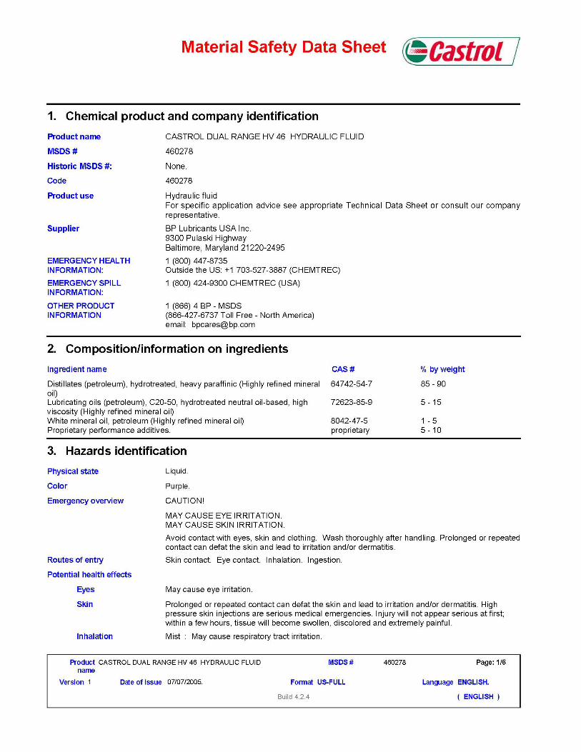
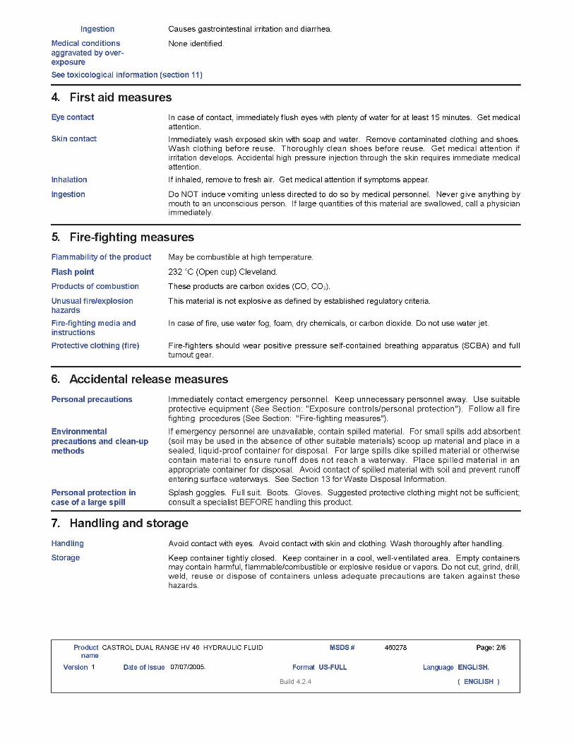
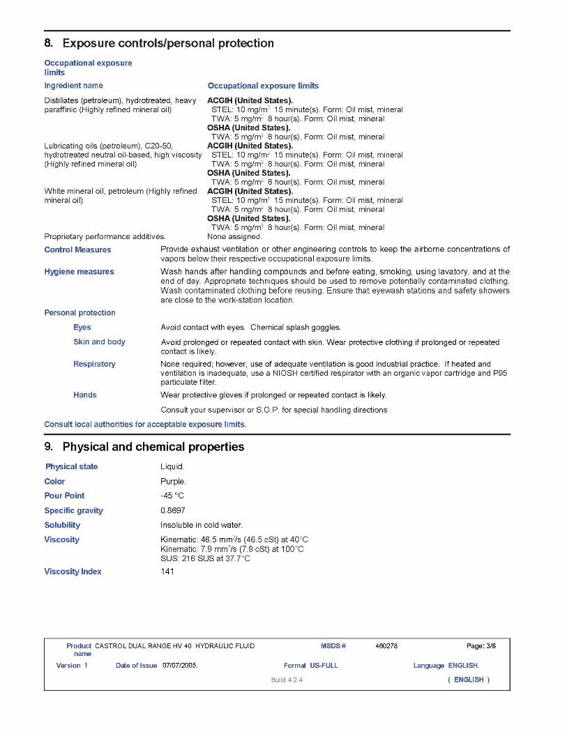
Fluids: 1. As of 1/1/03 the current standard hydraulic fluid is Castrol Dual Range HV46
hydraulic fluid. This is the fluid normally supplied by the factory and is suitable for a temperature range of –10 to +100 degrees Fahrenheit. When replacing or adding fluid to an Advance Lift, use only ISO 46 hydraulic fluid that is manufactured with a group II base oil. ISO 46 hydraulic fluid can be identified by its purple color.
2. From 3/25/85 until 12/31/02, Dexron II and Dexron Ill automatic transmission fluids
were supplied; they can be identified by pink coloring 3. Older units may be filled with 5W30 motor oil that is suitable for the same
temperature range and was supplied by the factory prior to 3/25/85. Be sure not to mix fluids. If you wish to switch from one fluid to another, drain the reservoir and system, then refill with the new fluid.
4. Do not use any other fluid unless it has been approved by the Advance lifts
engineering department. Brake fluids and other hydraulic fluids may damage the system’s seals or hoses. If it is required to switch from one fluid to another, drain the reservoir and system completely, and then refill with the factory approved new fluid.
5. Biodegradable and fire retardant fluids are available. Contact the factory for
specifications. It may be necessary to change some seals and/or hoses for total system compatibility, depending upon the specific model lift and the requested fluid.
Options:
For extremely warm temperature ranges of +120 to +140 degrees Fahrenheit, you may switch to 10W30 motor oil. If ambient temperatures are expected above 140 degrees, consult the factory. For extremely cold temperature ranges Advance Lifts recommends the use of a fluid heater, contact your distributor for more information and specifications.
Seals:
Generally, the seals in the unit are Buna-N-Nitrile and polyurethane. The hoses are either PVC for suction lines or braided wire for pressure lines. Always call the factory about special fluids rather than make assumptions on your own.
P 8-2

HD POWER UNIT
Standard Heavy-Duty units are supplied with external power units. Your power unit may vary in appearance with the addition or subtraction of features. Use this photo to identify
major components.
See Page P 8-4 for Hydraulic Diagram and Pages 9-3, 9-4 & 9-5 for Electrical Diagrams
P 8-3
Control Box Pump
Down Solenoid
Reservoir
Suction Line from Reservoir
Motor
Motor Overload Reset Button

MO
TOR
HYDRAULIC DIAGRAM FOR UNITS WITH INTERNALLY VALVED PUMPS
R
ES
ER
VO
IR
PR
ES
SU
RE
RE
LIE
F V
ALV
E. F
AC
TOR
Y
SE
T, D
O N
OT
AD
JUS
T
SU
CTI
ON
LIN
E
FILT
ER
IN
RE
SE
RV
OIR
CH
ECK
VA
LVE
INTE
RN
AL
FILT
ER
PR
ES
SU
RE
C
OM
PEN
SA
TED
FL
OW
CO
NTR
OL
VALV
E
DO
WN
S
OLE
NO
ID
½’’
SA
E 1
00R
2 H
YD
RA
ULI
C H
OS
E W
ITH
½
” FE
MA
LE J
IC F
ITTI
NG
S
(SU
PP
LIE
D B
Y O
THE
RS
)
½” M
ALE
JIC
FIT
TIN
GS
S
UP
PLI
ED
BY
AD
VA
NC
E
AT
PU
MP
AN
D F
ILTE
R
PIP
E O
N L
IFT
FLO
W C
ON
TRO
LS,
LOC
ATE
D IN
CY
LIN
DER
H
OU
SIN
G N
IPP
LE.
RE
FER
TO
PAG
E 8
-13
FOR
PR
OP
ER
O
RIE
NTA
TIO
N
CY
LIN
DE
RS
HY
DR
AU
LIC
DIA
GR
AM
FO
R H
D S
ER
IES
LIF
TS
N
UM
BE
R O
F C
YLI
ND
ER
CA
N C
HA
NG
E D
UE
TO
CA
PA
CIT
Y
PUM
P / V
ALVE
AS
SEM
BLY
P 8-4
(OP
TIO
NA
L)
MA
NU
AL
DO
WN
VA
LVE
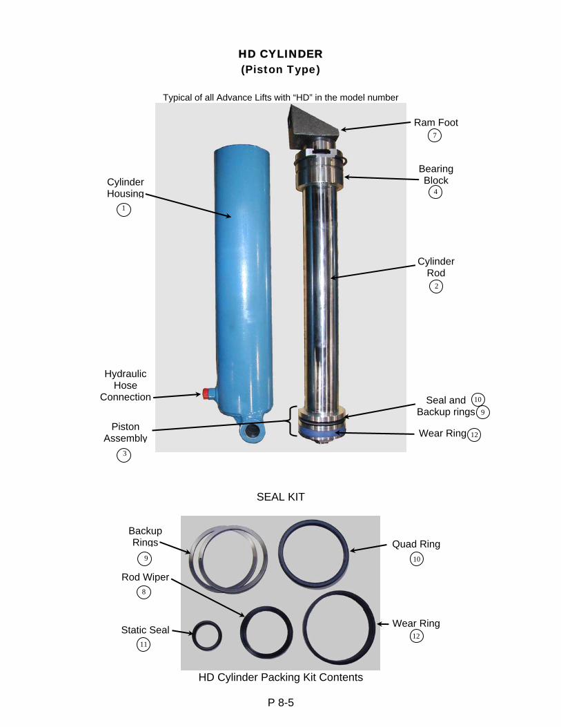
HD CYLINDER (Piston Type)
Typical of all Advance Lifts with “HD” in the model number
SEAL KIT
HD Cylinder Packing Kit Contents
P 8-5
Hydraulic Hose
Connection
Cylinder Rod
Piston Assembly
Bearing Block
Ram Foot
Cylinder Housing
Wear Ring
Seal and Backup rings
Static Seal
Rod Wiper
Backup Rings Quad Ring
Wear Ring
1
4
7
9
8
11
3
12
9
10
2
12
10
P 8-6
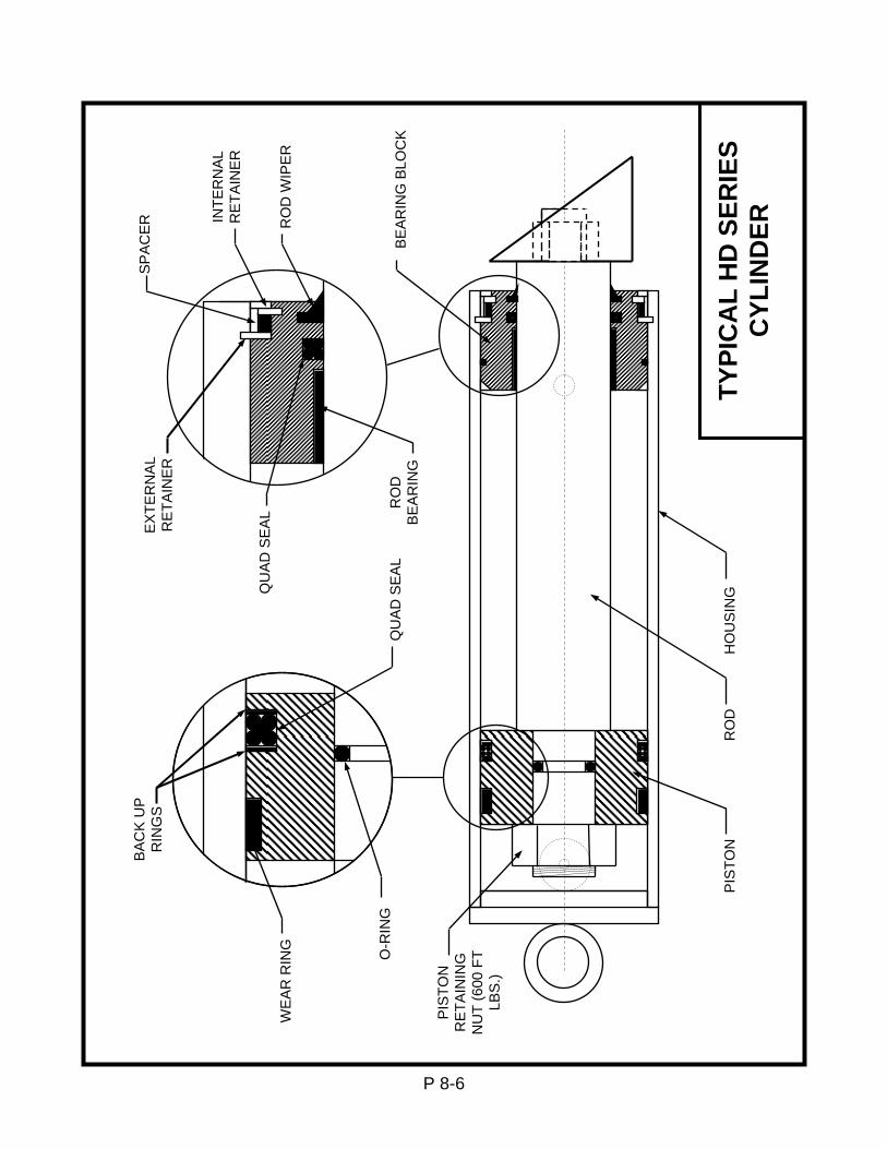
TYPI
CA
L H
D S
ERIE
S C
YLIN
DER
H
OU
SIN
G
RO
D
PIS
TON
PIS
TON
R
ETA
ININ
G
NU
T (6
00 F
T LB
S.)
O-R
ING
Q
UA
D S
EA
L
WE
AR
RIN
G
BA
CK
UP
R
ING
S
RO
D
BE
AR
ING
QU
AD
SE
AL
EX
TER
NA
L R
ETA
INE
R
SP
AC
ER
INTE
RN
AL
RE
TAIN
ER
RO
D W
IPE
R
BE
AR
ING
BLO
CK

REPAIR PROCEDURES FOR HD CYLINDERS
Tools & Supplied required:
“Lubriplate” and hydraulic fluid matching the existing fluid in the system for topping off the reservoir when finished. (Standard fluid is Rykon ISO 46 hydraulic oil) A five- (5) gallon bucket to collect fluid from the cylinders. Wrenches to disconnect hydraulic fittings. Emery cloth. Clean lint free cloths and hose caps. Clean work surface (butcher paper on top of most surfaces works well), with a means of holding the cylinder in a fixed position for disassembly and re-assembly. Safety legs supplied with each Advance unit. (1) Snap ring tool (Waldes Truarc external type #S-660 or Industrial pliers #P-104.) Cylinders hone (Craftsman glaze breaker #9K4633 or equivalent.)
Cylinder Removal: 1. Raise the empty lift and settle it securely on its safety bars. 2. Once settled securely, depress the down control an additional 20 seconds to relieve
any pressure from the hydraulic system. Remove the power connection to the power unit and mark with a warning label or lock the connection out to prevent unintended reconnection. (Check your company lockout and tag Standard Operating Procedures.)
3. Disconnect the hydraulic hose from the cylinder and cap the hose to prevent contamination.
4. Remove the ram foot retainers. 5. Remove the cylinder from the lift by freeing the upper pin first and swinging the
cylinder into an easily supported position. 6. Place the hose connection end of the cylinder in a 5-gallon bucket and force the
cylinder closed to drain the hydraulic fluid from the cylinder. Do not reuse the fluid unless you are sure it is contamination free by careful straining.
HD Series Cylinder Disassembly: 1. Secure the cylinder assembly in a vise using a pin through the cylinder clevis. Do not
secure the cylinder housing in a vise or damage to the housing will occur. 2. Compress the retaining ring with retaining ring pliers. 3. Push the cylinder rod back into the cylinder, and then pull forward quickly to remove
the entire front bearing and piston assembly. 4. At this point, when the packing set is pulled out past the groove in the front of the
cylinder, it will be cut by the groove and small shavings of the packing kit will be left behind. Clean out any shavings from the front groove after disassembly.
5. Using a screwdriver, lift and remove the two backup washers and the piston seal packing set. Caution: Do not nick or scratch the metal surfaces. Clean groove if necessary.
6. Lubricate the new rings and seal, gently stretch them over the piston, and place them in the seal grooves.
P 8-7

HD CYLINDER REBUILD PROCEDURES (CONTINUED) 7. Inspect the entire surface of the cylinder housing and its assemblies for scratches or
burrs. Carefully remove or clean any contaminates from the components before re-assembly.
8. If surface rust or scratching is evident on the inside of the cylinder housing, use an automatic cylinder hone to refinish the housing. Again, carefully remove the resulting contaminants before re-assembly.
9. Remove the static seal and the rod wiper. Remove the lock nut and slide the piston off the rod. Remove the static seal.
10. Slide the front bearing assembly off the rod, then carefully remove the flexible rod wiper, using a screwdriver to bend the seal inward to collapse and remove it. Inspect the groove for damage and debris and clean the assembly.
11. Lubricate and insert a new rod wiper, sliding it into its groove. 12. Inspect groove, then lubricate and slide a new static seal into place. Slide piston
back in place on the rod and tighten the lock nut. 13. Liberally lubricate the outside of the new packing kit and the groove in the cylinder
wall, align the piston carefully and then slide the entire assembly back into the cylinder.
14. Compress the retaining ring and slide the front bearing assembly into place. Release retaining ring and check to insure that it is entirely captured in the cylinder wall groove.
15. Replace cylinder(s) in lift, clean any foreign matter from the male and female hose connections and assemble hoses.
16. Clean up any spilled oil, as this may be misinterpreted, at some later date, as a leak. Re-installation of HD Cylinders: 1. Remount the cylinder in the lift and reattach the hose with special care to avoid
contamination. 2. Clean up any spilled oil to insure that it is not later misinterpreted as a new oil leak. 3. Connect the electrical power and cycle the lift several times, holding the down
control an extra 20 seconds each time to help bleed air from the hydraulic system. This will eliminate any “Spongy” operation. Check the oil level.
4. The lift is now ready to go back into service.
P 8-8

SECTION 9. ELECTRICAL DETAILS General Electrical Information:
The motor supplied as standard is a 208/230/460v 3-phase motor, with connection diagrams on the outside of the motor for low voltage (208/230V) or high voltage (460V). As any standard motor is rated for ±10% of voltage variation, this motor will operate properly, within ratings, at 208, 220, 230, 240, 440,460, and 480V, 3-phase supply.
If motor is intended for 208V line usage, some caution is advised, if you motor is a 230 volt motor, and your 208V line voltage drops to 207 volts, (a drop of only ½%), the motor will be operating at less than 10% in a marginal region. Wiring runs and actual voltage become very important. If you line voltage will be varying (due to loads elsewhere in the system, etc.) you may have an advantage by ordering as an option a 208V +/-10% motor.
To reverse the direction of rotation of a 3-phase motor, reverse any two of the three power leads to the motor. On single-phase motors, see wiring diagram on motor.
Field Changes in Voltage, 3-Phase (230V to 460V): A. Change transformer primary connections to 460V. B. Change overload protection to proper value as per currents in motor tables. Order
new overload; adjust new overload to motor full load current setting. Insure the overload is set to “manual” reset, not “automatic” to inure the equipment cannot re-start automatically.
C. Change motor connections for high (460V). D. Change plug and receptacle for power, if required. Field Changes in Voltage, 3-Phase (460V to 230V): A. Change transformer primary connections to 230V. B. Change overload protection to proper value as per currents in motor table. Order
new overload; adjust new overload to motor full load current setting. Insure the overload is set to “manual” reset, not “automatic” to insure the equipment cannot re-start automatically.
C. Change motor connections for low (230V). D. Change plug and receptacle for power, if required.
IMPORTANT: When changing voltages, insure motor rotation is correct.
P 9-1
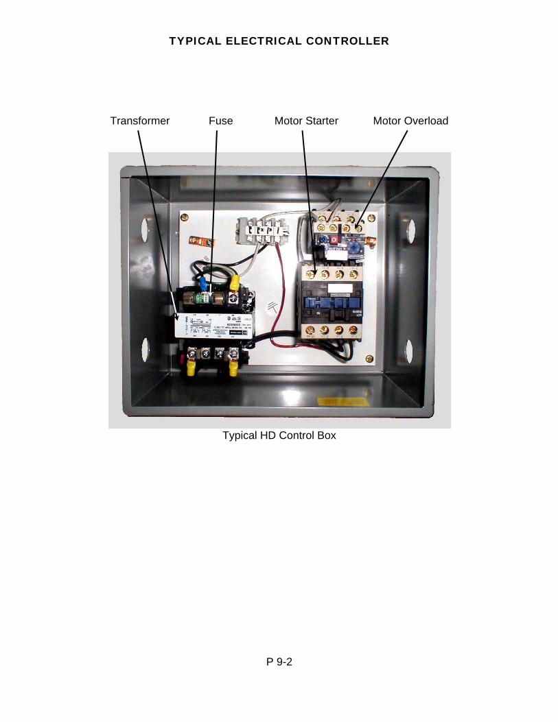
TYPICAL ELECTRICAL CONTROLLER
Transformer Fuse Motor Starter Motor Overload
Typical HD Control Box
P 9-2

P 9-3
5/22/06
X1
2
X2
1
H3
H2
4
X2
-
XF
X1 H4 H1
1L1
A1
6T3
4T2
2T1
6T3
4T2
2T1
5L3
3L2
96N
C
97N
O
98N
O
A2
95N
C
22 N
C
14 N
O
13 N
O
21 N
C
L 1 L 2
GROUND
N
TO DOWN SOLENOID
GROUND
ADVANCE LIFTS WIRING DIAGRAM FOR 230 VOLT SINGLE PHASE 5 HP
PUSH
BU
TTO
N
TRANSFORMER
TERMINAL STRIP
MOTOR STARTER OVERLOAD
BK
BK
BK
BK
BK
W
W
W
R
G
BK = BLACK G = GREEN R = RED W = WHITE
FLM
1
FLM
1
FNM
3-2
/10
DOWN
UP
STO
P
RES
ET
BK
LOW VOLTAGE LINE VOLTAGE LOW VOLTAGE (FIELD WIRED) LINE VOLTAGE (FIELD WIRED)
MOTOR
P1
T1
T8
T4
T5
3 4
4 3
INTERNAL MOTOR CONNECTIONS
1
P 9-4
5/23/06
X1
2
X2
1
H3
H2
4
X2
-
XF
X1 H4 H1
1L1
A1
6T3
4T2
2T1
6T3
4T2
2T1
5L3
3L2
96N
C
97N
O
98N
O
A2
95N
C
22N
C
14N
O
13N
O
21 N
C
L 1 L 2
GROUND
N
TO DOWN SOLENOID
GROUND
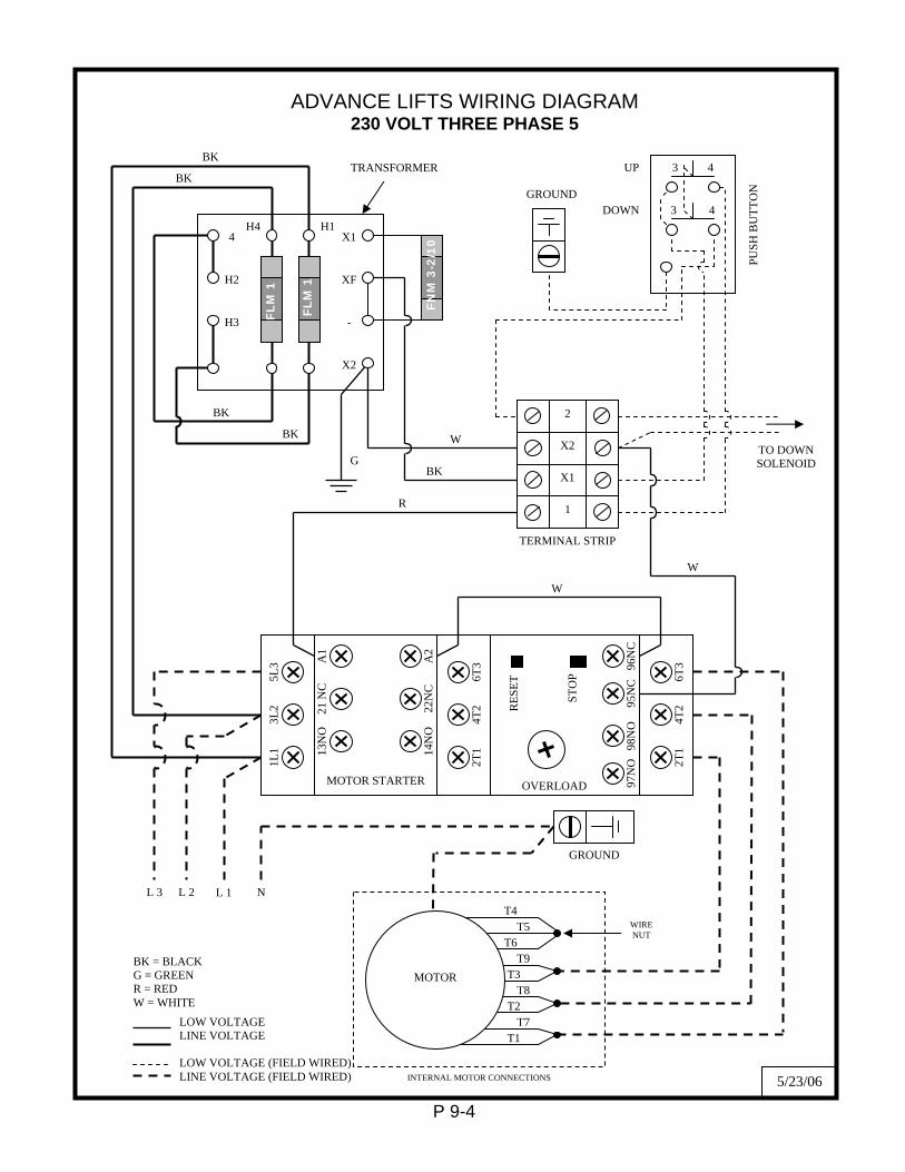
ADVANCE LIFTS WIRING DIAGRAM 230 VOLT THREE PHASE 5
PUSH
BU
TTO
N
TRANSFORMER
TERMINAL STRIP
MOTOR STARTER OVERLOAD
BK
BK
BK
BK
BK
W
W
W
R
G
BK = BLACK G = GREEN R = RED W = WHITE
FLM
1
FLM
1
FNM
3-2
/10
DOWN
UP
STO
P
RES
ET
L 3
3 4
3 4
MOTOR
T4 T5
T6 T9
T3 T8
T2 T7
INTERNAL MOTOR CONNECTIONS
T1
WIRE NUT
LOW VOLTAGE LINE VOLTAGE LOW VOLTAGE (FIELD WIRED) LINE VOLTAGE (FIELD WIRED)
X1
2
X2
1
H3
H2
4
X2
-
XF
X1 H4 H1
1L1
A1
6T3
4T2
2T1
6T3
4T2
2T1
5L3
3L2
96N
C
97N
O
98N
O
A2
95N
C
22N
C
14N
O
13N
O
21 N
C
L 1 L 2
GROUND
N
TO DOWN SOLENOID
GROUND
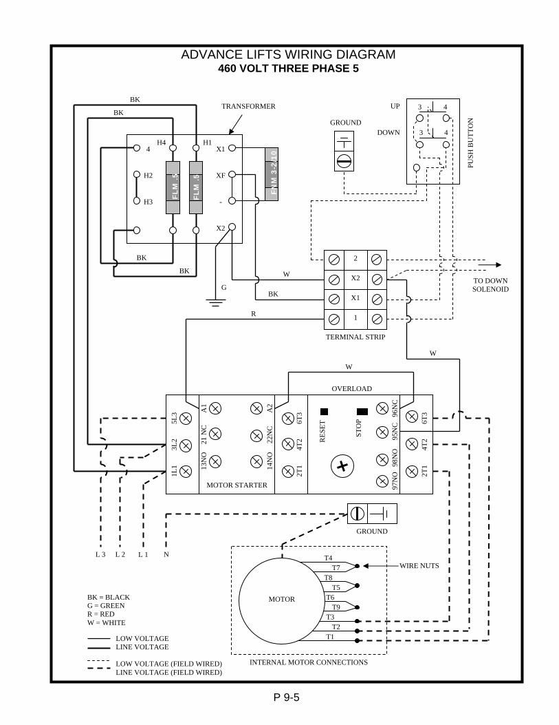
ADVANCE LIFTS WIRING DIAGRAM 460 VOLT THREE PHASE 5
PUSH
BU
TTO
N
TRANSFORMER
TERMINAL STRIP
MOTOR STARTER
OVERLOAD
BK
BK
BK
BK
BK
W
W
W
R
G
BK = BLACK G = GREEN R = RED W = WHITE
FLM
.5
FLM
.5
FNM
3-2
/10
DOWN
UP
STO
P
RES
ET
L 3
3
3 4
4
LOW VOLTAGE LINE VOLTAGE LOW VOLTAGE (FIELD WIRED) LINE VOLTAGE (FIELD WIRED)
MOTOR
T4 T7
T8 T5
T6 T9
T3 T2
INTERNAL MOTOR CONNECTIONS
T1
WIRE NUTS
P 9-5
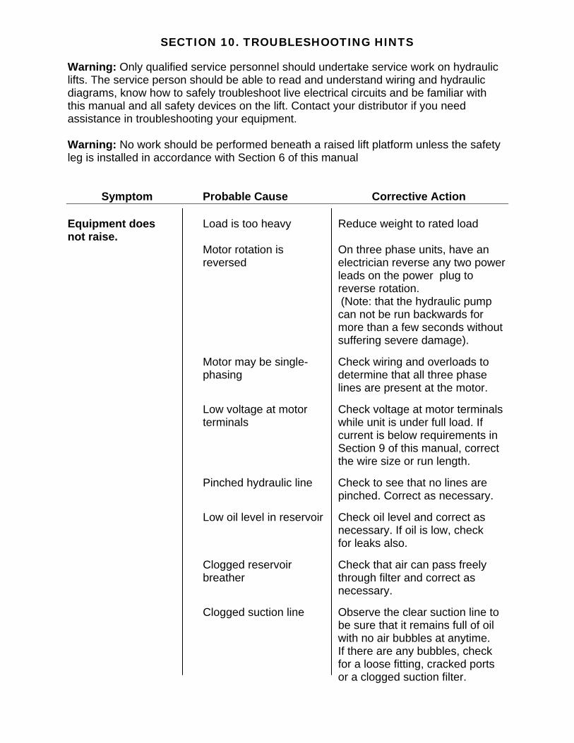
SECTION 10. TROUBLESHOOTING HINTS Warning: Only qualified service personnel should undertake service work on hydraulic lifts. The service person should be able to read and understand wiring and hydraulic diagrams, know how to safely troubleshoot live electrical circuits and be familiar with this manual and all safety devices on the lift. Contact your distributor if you need assistance in troubleshooting your equipment. Warning: No work should be performed beneath a raised lift platform unless the safety leg is installed in accordance with Section 6 of this manual Symptom Probable Cause Corrective Action Equipment does Load is too heavy Reduce weight to rated load not raise.
Motor rotation is On three phase units, have an reversed electrician reverse any two power leads on the power plug to
reverse rotation. (Note: that the hydraulic pump can not be run backwards for more than a few seconds without suffering severe damage).
Motor may be single- Check wiring and overloads to phasing determine that all three phase lines are present at the motor. Low voltage at motor Check voltage at motor terminals terminals while unit is under full load. If current is below requirements in Section 9 of this manual, correct the wire size or run length. Pinched hydraulic line Check to see that no lines are pinched. Correct as necessary. Low oil level in reservoir Check oil level and correct as necessary. If oil is low, check for leaks also. Clogged reservoir Check that air can pass freely breather through filter and correct as necessary. Clogged suction line Observe the clear suction line to be sure that it remains full of oil with no air bubbles at anytime. If there are any bubbles, check for a loose fitting, cracked ports or a clogged suction filter.

SECTION 10. TROUBLESHOOTING HINTS (CONTINUED) Symptom Probable Cause Corrective Action Equipment does Down solenoid wired Hold screwdriver on down not raise (continued) Incorrectly to energize solenoid and press “up” with up circuit switch. If you feel magnetism correct the lift wiring. Down solenoid stuck open Remove the down solenoid and check for free movement of the plunger. Pump failure Place gage on pump and if it does not produce 3200 psi., replace pump. Equipment raises Load is too heavy Reduce weight to rated too slowly Pinched hydraulic line Check to see that no lines are pinched. Correct as necessary. Dirt in down solenoid Clean the down so that it may fully close. Wrong oil for ambient See oil recommendations temperature in Section 8 of the manual. Dirt in reservoir breather Clean air breather. Low voltage at motor Check voltage at motor terminals while unit is under full load. If current is below requirements in section 9 of this manual, correct the wire size or run length.
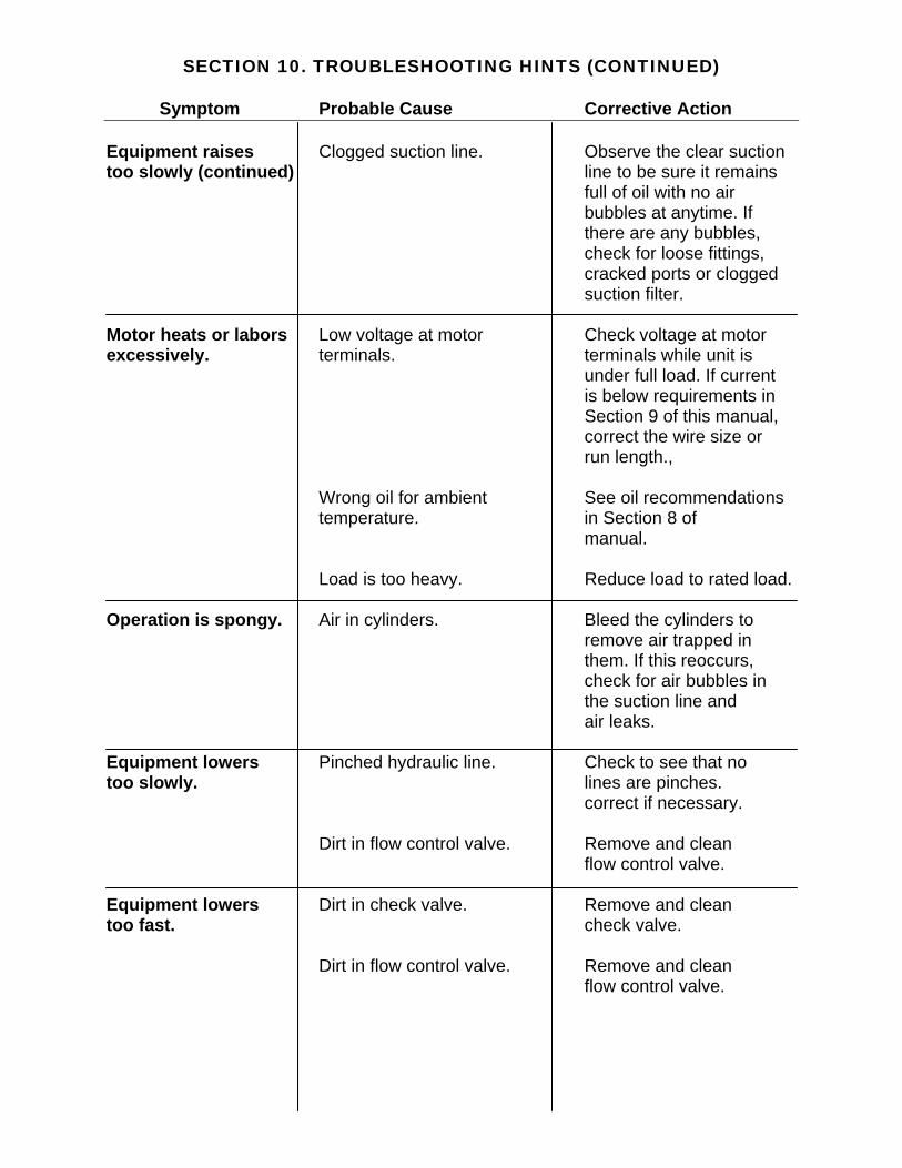
SECTION 10. TROUBLESHOOTING HINTS (CONTINUED) Symptom Probable Cause Corrective Action Equipment raises Clogged suction line. Observe the clear suction too slowly (continued) line to be sure it remains full of oil with no air bubbles at anytime. If there are any bubbles, check for loose fittings, cracked ports or clogged suction filter. Motor heats or labors Low voltage at motor Check voltage at motor excessively. terminals. terminals while unit is under full load. If current is below requirements in Section 9 of this manual, correct the wire size or run length., Wrong oil for ambient See oil recommendations temperature. in Section 8 of manual. Load is too heavy. Reduce load to rated load. Operation is spongy. Air in cylinders. Bleed the cylinders to remove air trapped in them. If this reoccurs, check for air bubbles in the suction line and air leaks. Equipment lowers Pinched hydraulic line. Check to see that no too slowly. lines are pinches. correct if necessary. Dirt in flow control valve. Remove and clean flow control valve. Equipment lowers Dirt in check valve. Remove and clean too fast. check valve. Dirt in flow control valve. Remove and clean flow control valve.

SECTION 10. TROUBLESHOOTING HINTS (CONTINUED) Symptom Probable Cause Corrective Action Lift raises, then Dirt in check valve. Remove and clean check Lowers. valve. Down solenoid wired Hold screwdriver on down Incorrectly. solenoid and if you feel magnetism correct the lift wiring.
Leaking cylinder Repack cylinders. packings. Lift raises, but Faulty solenoid valve Replace valve. will not lower. Down solenoid Rewire per diagram in incorrectly wired. Section 9 of this manual. Faulty solenoid coil. Replace coil. Obstruction in baseframe. Raise lift to clear obstruction then remove. Oil spraying out of Clogged air breather. A dirty breather filter may reservoir. build up positive pressure which will spray oil. Clean air breather. Lift will not raise Control voltage fuse Replace fuse. and motor will not blown. run. Motor starter overload Reset motor starter. Wrong voltage to unit. Check wiring in controller and on motor to confirm wiring is compatible with available power., Transformer connections Check and tighten loose. terminal screws on transformer. Transformer defective. Replace transformer. Pushbutton defective Replace pushbutton

SECTION 11. ADVANCE LIFTS INC. WARRANTY
For a period of one year from date of shipment from the Company’s plant, the Company agrees to replace or repair, free of charge, any defective parts, material, or workmanship on new equipment. This shall include electrical and hydraulic components. For a period of ten years or 250,000 cycles (whichever occurs first) from date of shipment from Company’s plant, the Company agrees to replace or repair any defective structure. Company authorization must be obtained prior to the commencement of any work. The Company reserves the right of choice between effecting repairs in the field or paying all freight charges and effecting the repairs at the Company’s plant. The Company further reserves the right of final determination in all warranty considerations. Evidence of overloading, abuse, or field modification of units without Company approval shall void this warranty. No contingent liabilities will be accepted.
P 11-1
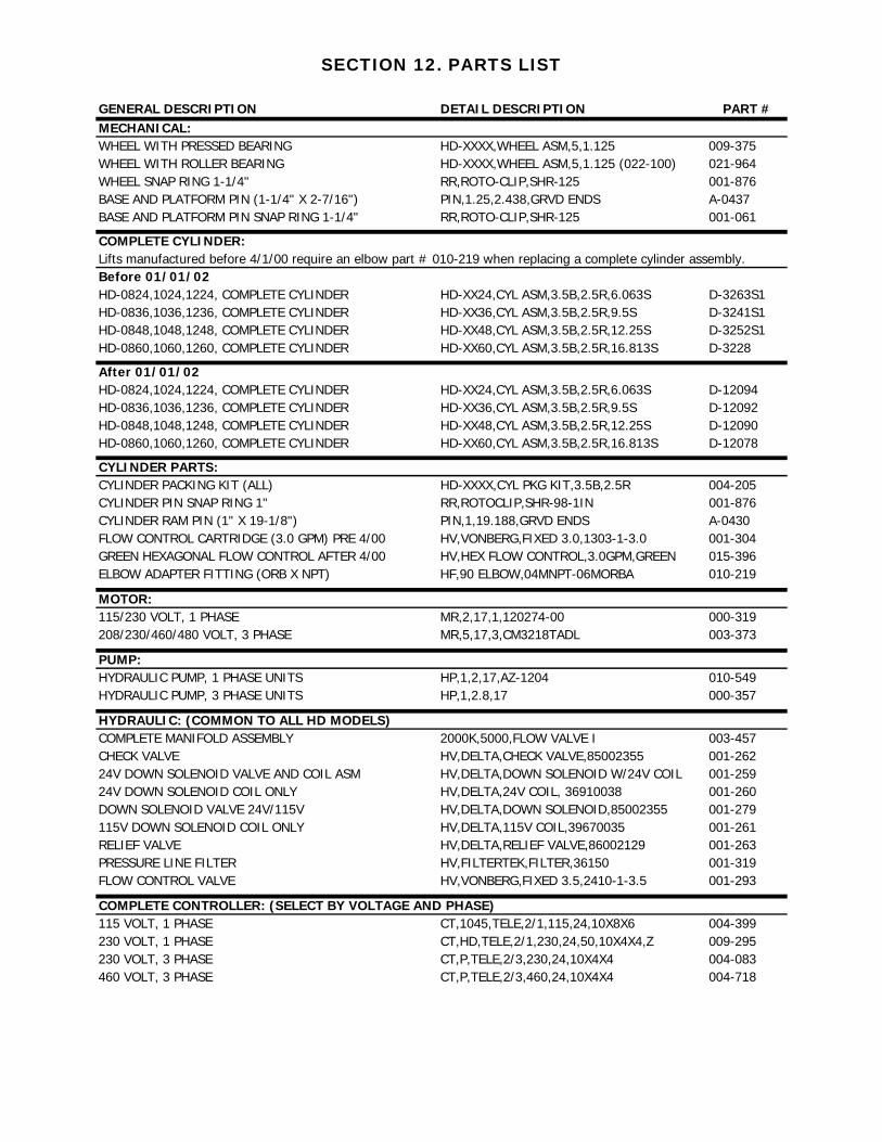
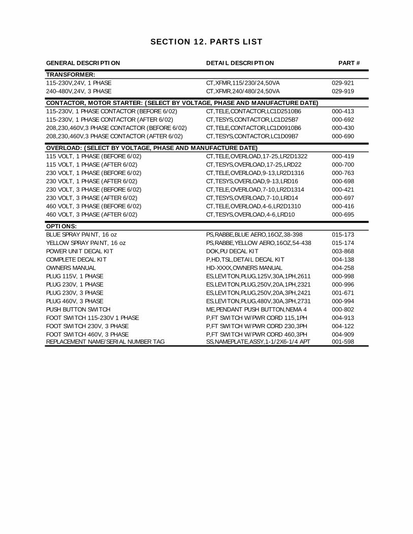
SECTION 12. PARTS LIST
GENERAL DESCRIPTION DETAIL DESCRIPTION PART #MECHANICAL:WHEEL WITH PRESSED BEARING HD-XXXX,WHEEL ASM,5,1.125 009-375WHEEL WITH ROLLER BEARING HD-XXXX,WHEEL ASM,5,1.125 (022-100) 021-964WHEEL SNAP RING 1-1/4" RR,ROTO-CLIP,SHR-125 001-876BASE AND PLATFORM PIN (1-1/4" X 2-7/16") PIN,1.25,2.438,GRVD ENDS A-0437BASE AND PLATFORM PIN SNAP RING 1-1/4" RR,ROTO-CLIP,SHR-125 001-061
COMPLETE CYLINDER:Lifts manufactured before 4/1/00 require an elbow part # 010-219 when replacing a complete cylinder assembly. Before 01/01/02HD-0824,1024,1224, COMPLETE CYLINDER HD-XX24,CYL ASM,3.5B,2.5R,6.063S D-3263S1HD-0836,1036,1236, COMPLETE CYLINDER HD-XX36,CYL ASM,3.5B,2.5R,9.5S D-3241S1HD-0848,1048,1248, COMPLETE CYLINDER HD-XX48,CYL ASM,3.5B,2.5R,12.25S D-3252S1HD-0860,1060,1260, COMPLETE CYLINDER HD-XX60,CYL ASM,3.5B,2.5R,16.813S D-3228
After 01/01/02HD-0824,1024,1224, COMPLETE CYLINDER HD-XX24,CYL ASM,3.5B,2.5R,6.063S D-12094HD-0836,1036,1236, COMPLETE CYLINDER HD-XX36,CYL ASM,3.5B,2.5R,9.5S D-12092HD-0848,1048,1248, COMPLETE CYLINDER HD-XX48,CYL ASM,3.5B,2.5R,12.25S D-12090HD-0860,1060,1260, COMPLETE CYLINDER HD-XX60,CYL ASM,3.5B,2.5R,16.813S D-12078
CYLINDER PARTS:CYLINDER PACKING KIT (ALL) HD-XXXX,CYL PKG KIT,3.5B,2.5R 004-205CYLINDER PIN SNAP RING 1" RR,ROTOCLIP,SHR-98-1IN 001-876CYLINDER RAM PIN (1" X 19-1/8") PIN,1,19.188,GRVD ENDS A-0430FLOW CONTROL CARTRIDGE (3.0 GPM) PRE 4/00 HV,VONBERG,FIXED 3.0,1303-1-3.0 001-304GREEN HEXAGONAL FLOW CONTROL AFTER 4/00 HV,HEX FLOW CONTROL,3.0GPM,GREEN 015-396ELBOW ADAPTER FITTING (ORB X NPT) HF,90 ELBOW,04MNPT-06MORBA 010-219
MOTOR: 115/230 VOLT, 1 PHASE MR,2,17,1,120274-00 000-319208/230/460/480 VOLT, 3 PHASE MR,5,17,3,CM3218TADL 003-373
PUMP:HYDRAULIC PUMP, 1 PHASE UNITS HP,1,2,17,AZ-1204 010-549HYDRAULIC PUMP, 3 PHASE UNITS HP,1,2.8,17 000-357
HYDRAULIC: (COMMON TO ALL HD MODELS)COMPLETE MANIFOLD ASSEMBLY 2000K,5000,FLOW VALVE I 003-457CHECK VALVE HV,DELTA,CHECK VALVE,85002355 001-26224V DOWN SOLENOID VALVE AND COIL ASM HV,DELTA,DOWN SOLENOID W/24V COIL 001-25924V DOWN SOLENOID COIL ONLY HV,DELTA,24V COIL, 36910038 001-260DOWN SOLENOID VALVE 24V/115V HV,DELTA,DOWN SOLENOID,85002355 001-279115V DOWN SOLENOID COIL ONLY HV,DELTA,115V COIL,39670035 001-261RELIEF VALVE HV,DELTA,RELIEF VALVE,86002129 001-263PRESSURE LINE FILTER HV,FILTERTEK,FILTER,36150 001-319FLOW CONTROL VALVE HV,VONBERG,FIXED 3.5,2410-1-3.5 001-293
COMPLETE CONTROLLER: (SELECT BY VOLTAGE AND PHASE)115 VOLT, 1 PHASE CT,1045,TELE,2/1,115,24,10X8X6 004-399230 VOLT, 1 PHASE CT,HD,TELE,2/1,230,24,50,10X4X4,Z 009-295230 VOLT, 3 PHASE CT,P,TELE,2/3,230,24,10X4X4 004-083460 VOLT, 3 PHASE CT,P,TELE,2/3,460,24,10X4X4 004-718
SECTION 12. PARTS LIST
GENERAL DESCRIPTION DETAIL DESCRIPTION PART #
TRANSFORMER:115-230V,24V, 1 PHASE CT,XFMR,115/230/24,50VA 029-921240-480V,24V, 3 PHASE CT,XFMR,240/480/24,50VA 029-919
CONTACTOR, MOTOR STARTER: (SELECT BY VOLTAGE, PHASE AND MANUFACTURE DATE)115-230V, 1 PHASE CONTACTOR (BEFORE 6/02) CT,TELE,CONTACTOR,LC1D2510B6 000-413115-230V, 1 PHASE CONTACTOR (AFTER 6/02) CT,TESYS,CONTACTOR,LC1D25B7 000-692208,230,460V,3 PHASE CONTACTOR (BEFORE 6/02) CT,TELE,CONTACTOR,LC1D0910B6 000-430208,230,460V,3 PHASE CONTACTOR (AFTER 6/02) CT,TESYS,CONTACTOR,LC1D09B7 000-690
OVERLOAD: (SELECT BY VOLTAGE, PHASE AND MANUFACTURE DATE)115 VOLT, 1 PHASE (BEFORE 6/02) CT,TELE,OVERLOAD,17-25,LR2D1322 000-419115 VOLT, 1 PHASE (AFTER 6/02) CT,TESYS,OVERLOAD,17-25,LRD22 000-700230 VOLT, 1 PHASE (BEFORE 6/02) CT,TELE,OVERLOAD,9-13,LR2D1316 000-763230 VOLT, 1 PHASE (AFTER 6/02) CT,TESYS,OVERLOAD,9-13,LRD16 000-698230 VOLT, 3 PHASE (BEFORE 6/02) CT,TELE,OVERLOAD,7-10,LR2D1314 000-421230 VOLT, 3 PHASE (AFTER 6/02) CT,TESYS,OVERLOAD,7-10,LRD14 000-697460 VOLT, 3 PHASE (BEFORE 6/02) CT,TELE,OVERLOAD,4-6,LR2D1310 000-416460 VOLT, 3 PHASE (AFTER 6/02) CT,TESYS,OVERLOAD,4-6,LRD10 000-695
OPTIONS:BLUE SPRAY PAINT, 16 oz PS,RABBE,BLUE AERO,16OZ,38-398 015-173YELLOW SPRAY PAINT, 16 oz PS,RABBE,YELLOW AERO,16OZ,54-438 015-174POWER UNIT DECAL KIT DOK,PU DECAL KIT 003-868COMPLETE DECAL KIT P,HD,TSL,DETAIL DECAL KIT 004-138OWNERS MANUAL HD-XXXX,OWNERS MANUAL 004-258PLUG 115V, 1 PHASE ES,LEVITON,PLUG,125V,30A,1PH,2611 000-998PLUG 230V, 1 PHASE ES,LEVITON,PLUG,250V,20A,1PH,2321 000-996PLUG 230V, 3 PHASE ES,LEVITON,PLUG,250V,20A,3PH,2421 001-671PLUG 460V, 3 PHASE ES,LEVITON,PLUG,480V,30A,3PH,2731 000-994PUSH BUTTON SWITCH ME,PENDANT PUSH BUTTON,NEMA 4 000-802FOOT SWITCH 115-230V 1 PHASE P,FT SWITCH W/PWR CORD 115,1PH 004-913FOOT SWITCH 230V, 3 PHASE P,FT SWITCH W/PWR CORD 230,3PH 004-122FOOT SWITCH 460V, 3 PHASE P,FT SWITCH W/PWR CORD 460,3PH 004-909REPLACEMENT NAME/SERIAL NUMBER TAG SS,NAMEPLATE,ASSY,1-1/2X6-1/4 APT 001-598


022307