Embed Size (px)
Citation preview

All Electric Injection Molding Machine

A new “Zero Story” begins here.
The motive force behind advanced molding technologyZero-molding aims to bring waste, defects and trouble vectors as close to zero as possible. We have pursued broader functioning and technological innovation that has enhanced the potential of our fully electric molding machines. All of these technologies are taking you to Zero-molding.
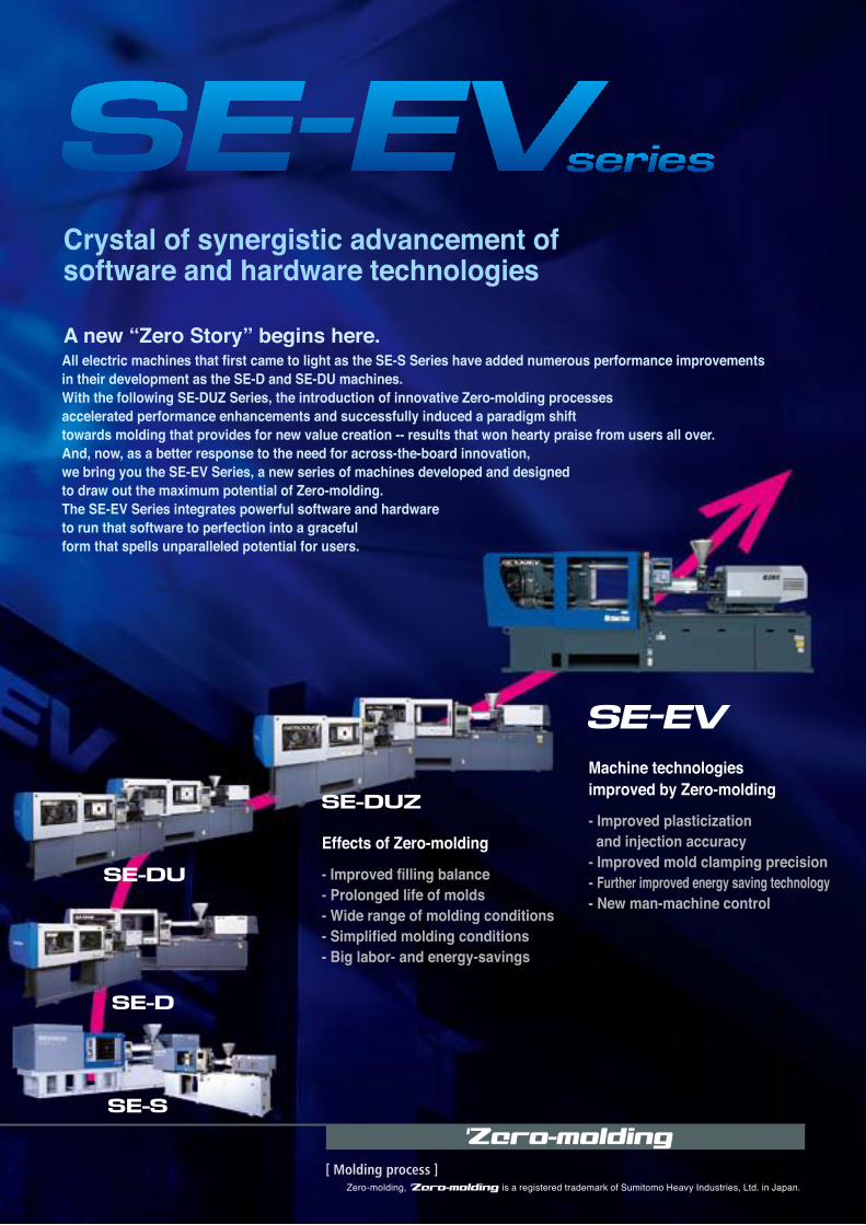
Crystal of synergistic advancement of software and hardware technologies
All electric machines that first came to light as the SE-S Series have added numerous performance improvements in their development as the SE-D and SE-DU machines.With the following SE-DUZ Series, the introduction of innovative Zero-molding processes accelerated performance enhancements and successfully induced a paradigm shift towards molding that provides for new value creation -- results that won hearty praise from users all over. And, now, as a better response to the need for across-the-board innovation, we bring you the SE-EV Series, a new series of machines developed and designed to draw out the maximum potential of Zero-molding. The SE-EV Series integrates powerful software and hardware to run that software to perfection into a graceful form that spells unparalleled potential for users.
Effects of Zero-molding
- Improved filling balance - Prolonged life of molds - Wide range of molding conditions - Simplified molding conditions - Big labor- and energy-savings
Machine technologies improved by Zero-molding
- Improved plasticization and injection accuracy - Improved mold clamping precision - Further improved energy saving technology- New man-machine control
A new “Zero Story” begins here.
The motive force behind advanced molding technologyZero-molding aims to bring waste, defects and trouble vectors as close to zero as possible. We have pursued broader functioning and technological innovation that has enhanced the potential of our fully electric molding machines. All of these technologies are taking you to Zero-molding.
Crystal of synergistic advancement of software and hardware technologies
All electric machines that first came to light as the SE-S Series have added numerous performance improvements in their development as the SE-D and SE-DU machines.With the following SE-DUZ Series, the introduction of innovative Zero-molding processes accelerated performance enhancements and successfully induced a paradigm shift towards molding that provides for new value creation -- results that won hearty praise from users all over. And, now, as a better response to the need for across-the-board innovation, we bring you the SE-EV Series, a new series of machines developed and designed to draw out the maximum potential of Zero-molding. The SE-EV Series integrates powerful software and hardware to run that software to perfection into a graceful form that spells unparalleled potential for users.
Effects of Zero-molding
- Improved filling balance - Prolonged life of molds - Wide range of molding conditions - Simplified molding conditions - Big labor- and energy-savings
Machine technologies improved by Zero-molding
- Improved plasticization and injection accuracy - Improved mold clamping precision - Further improved energy saving technology- New man-machine control
Zero-molding, is a registered trademark of Sumitomo Heavy Industries, Ltd. in Japan.

MCMMCM (Minimum Clamping Molding) uses means for detecting the minimum clamp force so as to enable molding at a low clamp force. Because clamp force is not applied beyond what is necessary, the benefits are far-reaching : reduced defects caused by gas, longer mold maintenance cycles, less damage to mold parts and reduced power consumption.
Evolved MCM via a high precision clamping mechanism
Good surface pressure balance at low clamp force
Clamp force feedback Low vibrations in high cycle molding
The SE-EV Series incorporates a linear guide support for the moving platen, a highly rigid frame and a high precision nozzle touch feature. Together, they improve precision at low clamp force in the form of clamping accuracy, clamp force balance, planarity and surface pressure. As a result, molding is stable even at extremely low clamp force.
Machine vibrations are greatly dampened even in high cycle molding, owing not only to the direct drive system but also a high precision platen support, a highly rigid frame and a servocontroller with a new algorithm.
A new mold clamping mechanism improves the accuracy of clamp force detection. Because the actually measured clamp force is feed back to the machine, molding can be done at a stable clamp force without being affected by the thermal expansion of the mold. Furthermore, clamp force is kept at a more stable level than was possible with earlier machines, even when working at low clamp force.
With earlier machines, more than the necessary clamp force was needed to balance the surface pressure applied to the mold. The SE-EV Series incorporates a new feature that balances this surface pressure even at low clamp force.
SE180DUZ SE180EV
High
Pressure
Low
High
Pressure
Low
Comparison of surface pressure distribution (at nozzle touch mode) Distributions of clamp force are measured by pressure measurement film.
500
400
300
200
100
0
Capability of following clamp force
Shot No.
clam
p fo
rce(
kN) 400
300
200
100
SE-DU
SE-DUZ
SE-EV
●High precision nozzle touch featurePrevents the platen from tilting under contact by the nozzle.
●Double center press platen Evenly distributes mold surface pressure. (Applicable with SE100EV and higher class machines)
●High precision moving platen support●Highly rigid frameMaintains planarity of mold halvesImproves straightness.
●Clamp force sensorOptimizes clamp force.
SE-DUZ
Tim
e(s)
SE-EV
Comparison of minimum mold open / close time
14% Less
4
StandardEquipment
StandardEquipment
StandardEquipment
StandardEquipment
OptionalEquipment
Patentpending
Patentpending
Patentpending
New functions
New functions
New functions
New functions

FFCFFC (Flow Front Control) optimizes flow control. This is made possible by ISC (Intelligent Servo Control) with a direct drive system at its core. Besides eliminating burrs and short shots, it markedly improves filling balance.
FFC evolved with the latest ISCⅡ
Injection speed controlcharacteristics
The screw is accurately controlled by employing the latest advances in servo control to control low inertia, high response servomotors. Moreover, enhanced accuracy in injection pressure and weighing speed detection makes plasticization, filling and pressure holding processes more precise and stable. And, filling pressure is lower and more balanced.
Owing to the latest in ISCⅡ, filling balance is improved even for multiple-shot molding where filling pressure can readily become imbalanced. Little difference in molding mass occurs between cavities when completely filled with a single shot, and mass variations stabilize with multiple shots.
Screw speed follow in flash processes is greatly improved even in high speed molding.
The evolved ISCⅡ improves basic performance, i.e., injection speed response, low speed injection follow, etc.
Further improved filling balance
Time(s)
C360 Injection speed response
-0.05 0 0.05 0.1 0.15 0.2 0.25
500
400
300
200
100
0
-100
20ms(350mm/s)
Inje
ctio
n sp
eed
(mm
/s) 2.5
2
1.5
1
0.5
00 1 2 3
Preset speed (mm/s)
Actu
al s
peed
(mm
/s)
C360 Low-speed control characteristics
Filling
Injection speed
Injection pressure
Screw position
Flash Hold pressureTime →
Inje
ctio
n sp
eed
/ pre
ssur
e →
Scre
w p
ositi
on →
Flash profiles
0.03
0.02
0.01
0.00
Fluctuation factor of parts weight among cavities
■SE-DU ■SE-DUZ ■SE-EV
Fluc
tuat
ion
fact
or (%
)
Cav.1 Cav.2 Cav.3 Cav.4 Cav.5 Cav.6 Cav.7 Cav.8
●Injection pressure detection●Screw rotational speed detectionDetection is 8x more accurate than with earlier machines, so plasticization is more stable.
●Low inertia, high response servomotors (For injection and weighing) Improved injection speed response and stabil i ty in repeated operations
●Newly developed servocontroller20% higher performance with improved motor controllability and stability
8 cavities coil bobbin
Conventional molding
Zero-molding
Cav.1 Cav.2 Cav.3 Cav.4 Cav.5 Cav.6 Cav.7 Cav8
5
StandardEquipment
StandardEquipment
StandardEquipment
Patentpending
New functionsNew functions
New functions
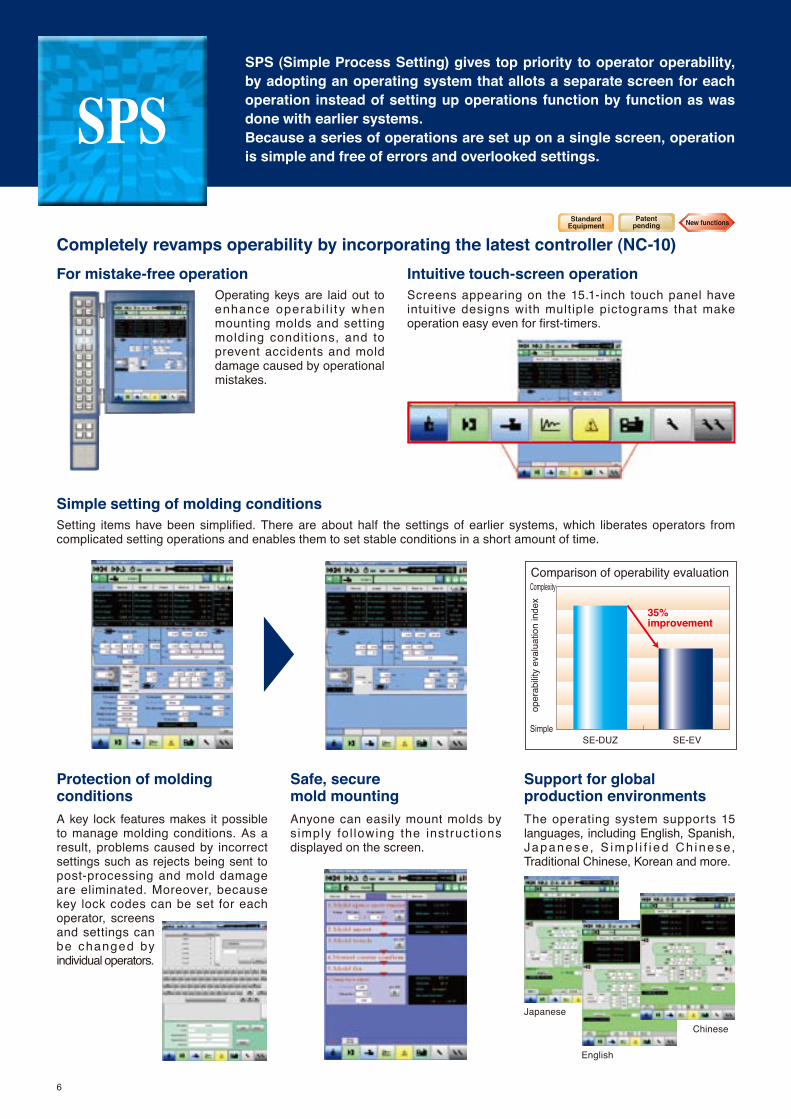
SPSSPS (Simple Process Setting) gives top priority to operator operability, by adopting an operating system that allots a separate screen for each operation instead of setting up operations function by function as was done with earlier systems. Because a series of operations are set up on a single screen, operation is simple and free of errors and overlooked settings.
Completely revamps operability by incorporating the latest controller (NC-10) For mistake-free operation
Simple setting of molding conditions
Protection of moldingconditions
Safe, secure mold mounting
Support for global production environments
Intuitive touch-screen operationScreens appearing on the 15.1-inch touch panel have intuitive designs with multiple pictograms that make operation easy even for first-timers.
Setting items have been simplified. There are about half the settings of earlier systems, which liberates operators from complicated setting operations and enables them to set stable conditions in a short amount of time.
A key lock features makes it possible to manage molding conditions. As a result, problems caused by incorrect settings such as rejects being sent to post-processing and mold damage are eliminated. Moreover, because key lock codes can be set for each operator, screens and settings can be changed by individual operators.
Anyone can easily mount molds by s imply fol lowing the instruct ions displayed on the screen.
The operating system supports 15 languages, including English, Spanish, Japanese, S imp l i f i ed Ch inese, Traditional Chinese, Korean and more.
Operating keys are laid out to enhance operabi l i t y when mounting molds and setting molding condit ions, and to prevent accidents and mold damage caused by operational mistakes.
30
25
20
15
10
5
0
操作性比較
操作性評価指数
SE-DUZ SE-EV
Comparison of operability evaluation
oper
abilit
y ev
alua
tion
inde
x
SE-DUZ SE-EVSimple
Complexity
35% improvement
Japanese
English
Chinese
6
StandardEquipment
Patentpending New functions
7
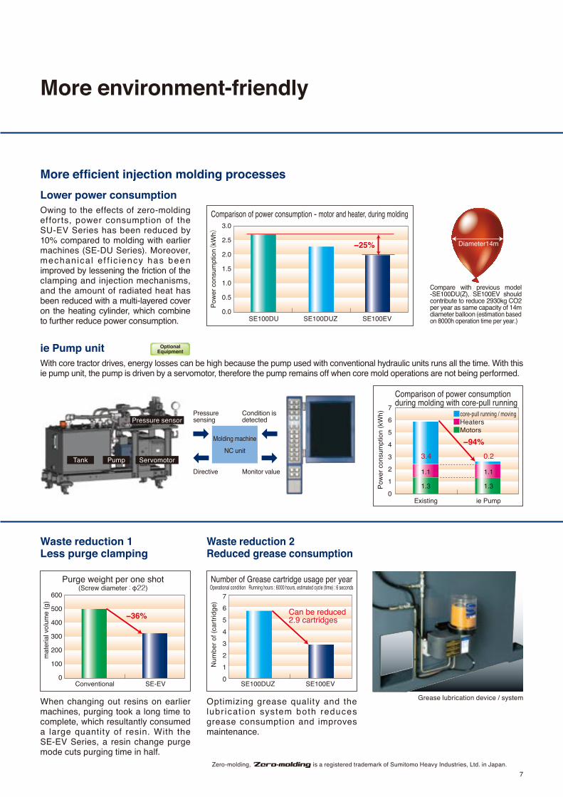
More efficient injection molding processes
ie Pump unit
Lower power consumption
Waste reduction 1Less purge clamping
Waste reduction 2Reduced grease consumption
3.0
2.5
2.0
1.5
1.0
0.5
0.0
消費電力量
SE100DUZSE100DU SE100EV
Pow
er c
onsu
mpt
ion(
kWh)
2.66
1
2.34
0
75%低減
2.00
1
3.0
2.5
2.0
1.5
1.0
0.5
0.0
Comparison of power consumption - motor and heater, during molding
SE100DUZSE100DU SE100EV
−25% Diameter14m
Compare with previous model -SE100DU(Z), SE100EV should contribute to reduce 2930kg CO2 per year as same capacity of 14m diameter balloon (estimation based on 8000h operation time per year.)
600
500
400
300
200
100
0
Purge weight per one shot(Screw diameter : φ22)
Conventional SE-EV
mat
eria
l vol
ume
(g)
−36%
7
6
5
4
3
2
1
0
Number of Grease cartridge usage per yearOperational condition Running hours : 6000 hours, estimated cycle (time) : 6 seconds
SE100DUZ SE100EV
Num
ber o
f (ca
rtrid
ge)
Can be reduced 2.9 cartridges
Owing to the effects of zero-molding efforts, power consumption of the SU-EV Series has been reduced by 10% compared to molding with earlier machines (SE-DU Series). Moreover, mechanica l ef f ic iency has been improved by lessening the friction of the clamping and injection mechanisms, and the amount of radiated heat has been reduced with a multi-layered cover on the heating cylinder, which combine to further reduce power consumption.
With core tractor drives, energy losses can be high because the pump used with conventional hydraulic units runs all the time. With this ie pump unit, the pump is driven by a servomotor, therefore the pump remains off when core mold operations are not being performed.
When changing out resins on earlier machines, purging took a long time to complete, which resultantly consumed a large quantity of resin. With the SE-EV Series, a resin change purge mode cuts purging time in half.
Optimizing grease quality and the lubr icat ion system both reduces grease consumption and improves maintenance.
7
6
5
4
3
2
1
0
Comparison of power consumption during molding with core-pull running
Existing ie Pump
■core-pull running / moving■Heaters■Motors
Pow
er c
onsu
mpt
ion
(kW
h)
1.3 1.3
1.11.1
3.4 0.2
−94%
More environment-friendly
Pressure sensing
Grease lubrication device / system
Directive
Condition is detected
OptionalEquipment
Zero-molding, is a registered trademark of Sumitomo Heavy Industries, Ltd. in Japan.
Pressure sensor
Molding machine
NC unit
Monitor valueTank Pump Servomotor
8
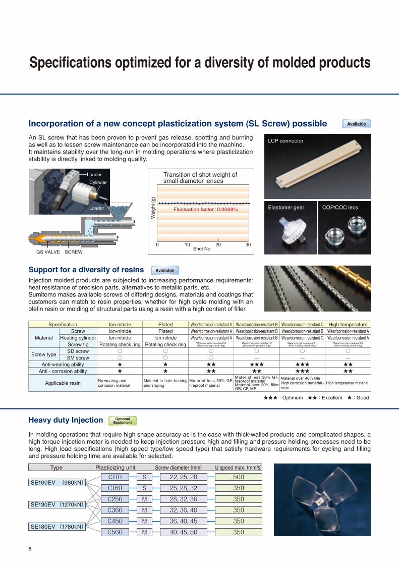
Specifications optimized for a diversity of molded products
Incorporation of a new concept plasticization system (SL Screw) possible
Support for a diversity of resinsInjection molded products are subjected to increasing performance requirements: heat resistance of precision parts, alternatives to metallic parts, etc.Sumitomo makes available screws of differing designs, materials and coatings that customers can match to resin properties, whether for high cycle molding with an olefin resin or molding of structural parts using a resin with a high content of filler.
An SL screw that has been proven to prevent gas release, spotting and burning as well as to lessen screw maintenance can be incorporated into the machine.It maintains stability over the long-run in molding operations where plasticization stability is directly linked to molding quality.
Specification Ion-nitride Plated Wear/corrosion-resistant A Wear/corrosion-resistant B Wear/corrosion-resistant C High temperature
MaterialScrew Ion-nitride Plated Wear/corrosion-resistant A Wear/corrosion-resistant B Wear/corrosion-resistant B Wear/corrosion-resistant A
Heating cylinder Ion-nitride Ion-nitride Wear/corrosion-resistant A Wear/corrosion-resistant B Wear/corrosion-resistant C Wear/corrosion-resistant AScrew tip Rotating check ring Rotating check ring Wear/corrosion-resistant A
(Non rotating check ring)Wear/corrosion-resistant B(Non rotating check ring)
Wear/corrosion-resistant C(Non rotating check ring)
Wear/corrosion-resistant A(Non rotating check ring)
Screw type SD screw ○ ○ ○ ○ ○ ○SM screw ○ ○ ○ — — —
Anti-wearing ability ★ ★ ★★ ★★★ ★★★ ★★Anti - corrosion ability ★ ★ ★★ ★★ ★★★ ★★
Applicable resin No wearing and corrosion material
Material to hate burning and staying
Material less 30% GF, fireproof material
Material less 30% GF, fireproof materialMaterial over 30% filler GB, CF, MR
Material over 40% filleHigh corrosion material / resin
High temperature material
★★★:Optimum ★★:Excellent ★:Good
Loader
Loader
SCREWGS VALVE
Cylinder
0 10 20 30
Transition of shot weight of small diameter lenses
Shot No.
Fluctuation factor:0.0068%
Wei
ght (
g)
Heavy duty Injection
In molding operations that require high shape accuracy as is the case with thick-walled products and complicated shapes, a high torque injection motor is needed to keep injection pressure high and filling and pressure holding processes need to be long. High load specifications (high speed type/low speed type) that satisfy hardware requirements for cycling and filling and pressure holding time are available for selected.
Type Plasticizing unit Screw diameter (mm) IJ speed max. (mm/s)S
S
M
M
M
M
22, 25, 28
25, 28, 32
28, 32, 36
32, 36, 40
36, 40, 45
40, 45, 50
500
350
350
350
350
350
C110
C160
C250
C360
C450
C560
SE100EV (980kN)
SE130EV (1270kN)
SE180EV (1760kN)
LCP connector
Elastomer gear COP/COC lecs
Available
Available
OptionalEquipment

Standard Equipment
Optional Equipment
Plasticizing & injection unit1 SD lon-nitride screw assembly (Open nozzle)2 Heater 5 division control (φ18~20 : 4 division)3 Water cooling jacket temperature control device 4 Standard heated cylinder cover5 2-modes temperature control (production/standby)6 Cold screw startup protection (Interlock variable timer attaching)7 Protective purge shield (with limit switch)8 Programming control of injection9 Programming control hold pressure
10 Plasticizing program – multi-stage control11 Screw pull back (after screw rotating/after holding pressure)12 V-P switchover controller (pressure, position)13 Injection/Holding response 10-mode14 Mold open operation during plasticizing (needle nozzle drive control)15 Sprue break stroke remote setting (Detection of nozzle touch, Moving time)16 High nozzle touch force and precision unit (Nozzle touch force : 3 stages changeable)
Clamp unit 1 Center press platen2 Moving platens support device – linear guide3 Programmed control of mold opening/closing speed (5-step/3-step) 4 Mold protection5 Low pressure clamping unit6 Standby mode for mold mounting (low mold closing/opening speed)7 Remote control of clamp force
8 Remote control of mold space 9 Ejector (with selective multi-functions, protrusion delay timer, speed, stroke, pressure & return check)
10 Ejector 2-speed control11 Ejector protrusion during mold opening12 Ejector protrusion during mold closing 13 Ejector unit with brake14 Valve gate drive circuit (control circuit only) Note.415 Ejector plate retun signal (Input signal for molding machine) Connecting by metal concent Note.416 Take-out robot connection circuit Note.417 Ejected products sensor circuit Note.4
Control unit1 Zero-molding system2 15 inch TFT Color LCD screen3 Molding profiles display functions (mold profiles storage, cursor, display and so on)4 Statistics product quality control (Actual value control, Quality transition graph)5 Production control 6 Internal memory of mold conditions7 Automatic starting system (heater warming, heater start, machine stop) Note.48 Operation guide for maintenannce9 USB connection circuit
10 Signal output for machine condition Note.411 Auxiliary facility monitor (1ch) Note.412 Cylinder heater temperature monitor (all zones)13 Heater band burnout monitor 14 Alarm monitor (7 items)15 Abnormal history (item and time)
Plasticizing selection1 Hard chromium plating screw assembly2 Wear & corrosion resistant A screw assembly3 Wear & corrosion resistant B screw assembly4 Wear & corrosion resistant C screw assembly5 High-temperature screw assembly (Max. temp. 450℃)6 SM screw assembly7 SL screw assembly8 Screw tip set - rotation type TiN coating9 FTCⅡnozzle (Open nozzle : φ18~φ36, Less than SE130EV)
10 Extension nozzle11 Cylinder nozzle12 Needle valve shut-off nozzle ( nozzle open/close with pneumatic cylinder)13 High capacity heater14 Zone 1 high capacity heater (Less than C160 are standard)15 High insulated cylinder cover – 3 stratified covers
Plasticizing & injection unit1 FTC nozzle electric control circuit (φ18~φ36 screw)2 FTC nozzle electric control circuit (φ18~φ36 screw)3 Needle valve shut-off nozzle drive circuit4 Resin temperature finder (only available with needle valve shut-off nozzle)5 Plating resin inlet of cooling water jacket 6 Standard type hopper7 Hopper swivel mounting plate (unavailable for C50)8 High efficiency nozzle contact (Nozzle touch force release pressure)9 V/P switchover by mold cavity pressure
10 Heavy duty injection11 GS loader control circuit
Control & monitor unit1 Leak circuit breaker (AC200V, 220V 3φ3W+E Japan and Asia only)2 Mold temperature monitor 2 zone (without thermocouple and type K)3 Mold temperature monitor 4 zone (without thermocouple and type K) (unavailable for SE100EV)4 Mold temp. controller (2 zone) 5 Mold temp. controller (4 zone) 6 Auxiliary facility monitor (STD.+2ch) Note.47 Analog circuit output for molding profile8 Automatic starting system (Heater+water supply+external output signal)9 Revolving alarm lamp
10 Multi fanction 3 colors LED alarm lamp11 Motion 0712 4-Lines closed circuit cooling water piping connection (with flow detector, stop valve)13 2-Lines closed circuit cooling water piping connection (with flow detector, stop valve)
14 Electric power supply socket15 Electric power supply socket for tools (with transformer)16 iii-System Standard Edition
Clamp unit1 Double center press platen (SE100EV~SE180EV)2 High precision heat insulating plate (5mm, 10mm, cross type) 3 Valve gate drive circuit (control circuit & pneumatic circuit)4 Pneumatic ejector5 Cavity ventilator6 Hydraulic core pull control circuit 1 lines (control circuit+Piping)7 Hydraulic core pull control circuit (remot, ie pump hydraulic driving unit)8 Pneumatic core pull circuit 1 lines 9 Core rotation control circuit (motor drive:1.5kw or less)
10 SPI take-out robot connection circuit Note.411 Products chute12 Increased ejector force(SE100EV~SE180EV:59kN)13 Extended ejector stroke(SE100EV~180EV:150mm)14 Ejector compression device(SE100EV~SE180EV:49kN)15 Valve gate drive circuit (ie pump hydraulic driving unit)16 Die Clamp control unit17 Full metallic toggle cover18 Mold space extension 50mm Note.319 Mold space extension 100mm Note.3
Spare parts and accessories1 Spare parts (Mechanical parts : Brake lining, Lub. parts)2 Spare parts (Electrical parts : Thermocouple)3 Spare parts for export. (Encorder,Limit switch, and Inducjive proximity sensors)4 Leveling pads (for one machine)5 Anchor bolts (for one machine)6 Locating ring (Transition fit) ( I.D.φ100/O.D.φ120) (only for SE180EV)7 Locating ring (Transition fit) ( I.D.φ110/O.D.φ120) (only for SE180EV)8 Tools A9 Ejector rods
10 Grease gun11 Grease cartridge for Automatic Lub (700cc)12 Grease cartridge for Manual Lub (400cc) Plasticizing 13 Easy Clamp
Equipment
9Zero-molding, is a registered trademark of Sumitomo Heavy Industries, Ltd. in Japan.
Note.1 Specifications may subject to change without notice for performance improvements.Note.2 The export of this product for use for or in development and/or production of massive destruction arms and weapons(nuclear weapons, biological weapons, missiles) or the export of this product to any person, party or corporation engaged or involved in the development and/or production of above described goods is subject to the authorization of the Japanese government pursuant to Foreign Exchange and Foreign Trade Control Law. Note.3 The overall machine length is also up 100mm.Note.4 Input / output signals are provided with dry contact (zero voltage). (If signal required voltage, please request for such option)

Items Unit SE50EV SE75EV SE100EV SE130EV SE180EV
●Clamp unit
Clamp system Double toggle (5 point) Double toggle (5 point) Double toggle (5 point) Double toggle (5 point) Double toggle (5 point)
Clamp force kN 500 750 1000 1300 1800
Clearance between tie-bars (L×H) mm 360×360 410×410 460×460 510×510 560×560
Clamp platens max. (L×H) mm 500×500 580×580 650×650 720×720 800×795
Daylight mm 600 710 800 850 950
Mold opening stroke mm 250 300 350 400 450
Platen speed max. mm/s MAX.1200 MAX.1200 MAX.1200 MAX.1200 MAX.1200
Mold installation height (min.~max.) mm 160~350 160~410 180~450 180~450 200~500
Locating ring diameter mm φ100 φ100 φ100 φ100 φ120
Ejector type Electric (5 point) Electric (5 point) Electric (5 point) Electric (5 point) Electric (5 point)
Ejector force kN 21 26 32 32 45
Ejector speed max. mm/s MAX.333 MAX.333 MAX.333 MAX.333 MAX.333
Ejector stroke mm 70 80 100 100 120
●Injection unit
Plasticizing capacity C65 C110 C160 C110 C160 C250 C110 C160 C250 C360 C160 C250 C360 C450 C250 C360 C450 C560
Screw diameter S S S S S M S S M M S M M M M M M Mmm 18 20 22 25 22 25 28 25 28 32 22 25 28 25 28 32 28 32 36 22 25 28 25 28 32 28 32 36 32 36 40 25 28 32 28 32 36 32 36 40 36 40 45 28 32 36 32 36 40 36 40 45 40 45 50
Injection pressure max.【Note1, Note2】 MPa 274 265 220 170 274 212 174 274 218 167 274 212 174 274 218 167 284 217 171 274 212 174 274 218 167 284 217 171 273 215 167 274 218 167 284 217 171 273 215 167 259 209 165 284 217 171 273 215 167 259 209 165 274 216 175
Hold pressure max.【Note1, Note2】 MPa 274 265 220 170 274 212 174 274 218 167 274 212 174 274 218 167 284 217 171 274 212 174 274 218 167 284 217 171 273 215 167 274 218 167 284 217 171 273 215 167 259 209 165 284 217 171 273 215 167 259 209 165 274 216 175
Theoretical injection capacity cm3 20 25 30 38 40 51 64 51 64 84 40 51 64 51 64 84 86 113 143 40 51 64 51 64 84 86 113 143 129 163 201 51 64 84 86 113 143 129 163 201 163 201 254 86 113 143 129 163 201 163 201 254 201 254 314
Max. injected mass (GPPS) g 19 24 28 37 38 49 61 49 61 80 38 49 61 49 61 80 83 108 137 38 49 61 49 61 80 83 108 137 124 156 193 49 61 80 83 108 137 124 156 193 156 193 244 83 108 137 124 156 193 156 193 244 193 244 302
Plasticizing rate max. (GPPS) kg/h 10 13 18 26 18 26 37 26 37 53 18 26 37 26 37 53 37 53 76 18 26 37 26 37 53 37 53 76 53 76 101 26 37 53 37 53 76 53 76 101 76 101 136 37 53 76 53 76 101 76 101 136 101 136 193
Injection rate max. cm3/s 140 173 209 270 190 245 308 196 246 322 190 245 308 196 246 322 216 281 356 190 245 308 196 246 322 216 281 356 281 356 440 196 246 322 216 281 356 281 356 440 356 440 557 216 281 356 281 356 440 356 440 557 440 557 687
Screw stroke mm 78 104 104 104 104 140 104 104 140 160 104 140 160 160 140 160 160 160
Injection speed max. mm/s 550 500 400 500 400 350 500 400 350 350 400 350 350 350 350 350 350 350
Screw driving system Electric Electric Electric Electric Electric
Screw speed max. min-1 400 400 400 400 400 400 400 400 400 400 400 400 400 400 400 400 400 400
Number of temperature control zone 4 5 5 5 5 5 5 5 5 5 5 5 5 5 5 5 5 5 5
Heater capacity kW 2.9 3.3 3.6 4.2 3.6 4.2 4.8 4.2 4.8 5.4 3.6 4.2 4.8 4.2 4.8 5.4 6.5 7.5 8.4 3.6 4.2 4.8 4.2 4.8 5.4 6.5 7.5 8.4 7.5 8.4 10.3 4.2 4.8 5.4 6.5 7.5 8.4 7.5 8.4 10.3 8.4 10.3 11.5 6.5 7.5 8.4 7.5 8.4 10.3 8.4 10.3 11.5 10.3 11.5 12.6
Nozzle contact force kN {tf} 14 14 14 14 43 43 14 43 43 43 43 43 43 43 43 43 43 43
Moving stroke mm 250 250 250 285 285 300 305 305 320 320 320 335 335 335 380 380 380 380
Protrusion 30 30 30 30 30 45 30 30 45 45 30 45 45 45 65 65 65 65
Hopper capacity ℓ 15 15 15 15 15 30 15 15 30 30 15 30 30 50 30 30 50 50
●Machine dimension & mass
Machine dimension (L×W×H)【Note3】 mm 3617×1144×1575 3617×1144×1575 3617×1144×1575 4187×1212×1566 4187×1212×1566 4187×1212×1566 4502×1192×1772 4502×1192×1772 4502×1192×1837 4502×1192×1837 4732×1292×1817 4732×1292×1882 4732×1292×1882 4732×1292×1977 5121×1362×1923 5121×1362×1923 5121×1362×2018 5121×1362×2018
Machine mass t 2.2 2.3 2.4 3.0 3.1 3.2 3.7 3.8 4.0 4.1 4.6 4.8 4.9 5.0 6.0 6.1 6.2 6.4
Main specification
10
Note1. The maximum injection pressure and hold pressure are calculated values, which are the outputs of the machine, but not the resin pressures.Note2. The maximum injection pressure and hold pressure are no pressures that can be generated continuously.Note3. The total length of the machine is the value measured up to the advance position of the injection unit with a smallest screw installed.Note4. Specifications subject to change without notice for performance improvementNote5. The dimensions are Japanese specification.◇This series originally comply to safety standards of Japan, the US, in addition, also China GB22530 and KC mark.

Items Unit SE50EV SE75EV SE100EV SE130EV SE180EV
●Clamp unit
Clamp system Double toggle (5 point) Double toggle (5 point) Double toggle (5 point) Double toggle (5 point) Double toggle (5 point)
Clamp force kN 500 750 1000 1300 1800
Clearance between tie-bars (L×H) mm 360×360 410×410 460×460 510×510 560×560
Clamp platens max. (L×H) mm 500×500 580×580 650×650 720×720 800×795
Daylight mm 600 710 800 850 950
Mold opening stroke mm 250 300 350 400 450
Platen speed max. mm/s MAX.1200 MAX.1200 MAX.1200 MAX.1200 MAX.1200
Mold installation height (min.~max.) mm 160~350 160~410 180~450 180~450 200~500
Locating ring diameter mm φ100 φ100 φ100 φ100 φ120
Ejector type Electric (5 point) Electric (5 point) Electric (5 point) Electric (5 point) Electric (5 point)
Ejector force kN 21 26 32 32 45
Ejector speed max. mm/s MAX.333 MAX.333 MAX.333 MAX.333 MAX.333
Ejector stroke mm 70 80 100 100 120
●Injection unit
Plasticizing capacity C65 C110 C160 C110 C160 C250 C110 C160 C250 C360 C160 C250 C360 C450 C250 C360 C450 C560
Screw diameter S S S S S M S S M M S M M M M M M Mmm 18 20 22 25 22 25 28 25 28 32 22 25 28 25 28 32 28 32 36 22 25 28 25 28 32 28 32 36 32 36 40 25 28 32 28 32 36 32 36 40 36 40 45 28 32 36 32 36 40 36 40 45 40 45 50
Injection pressure max.【Note1, Note2】 MPa 274 265 220 170 274 212 174 274 218 167 274 212 174 274 218 167 284 217 171 274 212 174 274 218 167 284 217 171 273 215 167 274 218 167 284 217 171 273 215 167 259 209 165 284 217 171 273 215 167 259 209 165 274 216 175
Hold pressure max.【Note1, Note2】 MPa 274 265 220 170 274 212 174 274 218 167 274 212 174 274 218 167 284 217 171 274 212 174 274 218 167 284 217 171 273 215 167 274 218 167 284 217 171 273 215 167 259 209 165 284 217 171 273 215 167 259 209 165 274 216 175
Theoretical injection capacity cm3 20 25 30 38 40 51 64 51 64 84 40 51 64 51 64 84 86 113 143 40 51 64 51 64 84 86 113 143 129 163 201 51 64 84 86 113 143 129 163 201 163 201 254 86 113 143 129 163 201 163 201 254 201 254 314
Max. injected mass (GPPS) g 19 24 28 37 38 49 61 49 61 80 38 49 61 49 61 80 83 108 137 38 49 61 49 61 80 83 108 137 124 156 193 49 61 80 83 108 137 124 156 193 156 193 244 83 108 137 124 156 193 156 193 244 193 244 302
Plasticizing rate max. (GPPS) kg/h 10 13 18 26 18 26 37 26 37 53 18 26 37 26 37 53 37 53 76 18 26 37 26 37 53 37 53 76 53 76 101 26 37 53 37 53 76 53 76 101 76 101 136 37 53 76 53 76 101 76 101 136 101 136 193
Injection rate max. cm3/s 140 173 209 270 190 245 308 196 246 322 190 245 308 196 246 322 216 281 356 190 245 308 196 246 322 216 281 356 281 356 440 196 246 322 216 281 356 281 356 440 356 440 557 216 281 356 281 356 440 356 440 557 440 557 687
Screw stroke mm 78 104 104 104 104 140 104 104 140 160 104 140 160 160 140 160 160 160
Injection speed max. mm/s 550 500 400 500 400 350 500 400 350 350 400 350 350 350 350 350 350 350
Screw driving system Electric Electric Electric Electric Electric
Screw speed max. min-1 400 400 400 400 400 400 400 400 400 400 400 400 400 400 400 400 400 400
Number of temperature control zone 4 5 5 5 5 5 5 5 5 5 5 5 5 5 5 5 5 5 5
Heater capacity kW 2.9 3.3 3.6 4.2 3.6 4.2 4.8 4.2 4.8 5.4 3.6 4.2 4.8 4.2 4.8 5.4 6.5 7.5 8.4 3.6 4.2 4.8 4.2 4.8 5.4 6.5 7.5 8.4 7.5 8.4 10.3 4.2 4.8 5.4 6.5 7.5 8.4 7.5 8.4 10.3 8.4 10.3 11.5 6.5 7.5 8.4 7.5 8.4 10.3 8.4 10.3 11.5 10.3 11.5 12.6
Nozzle contact force kN {tf} 14 14 14 14 43 43 14 43 43 43 43 43 43 43 43 43 43 43
Moving stroke mm 250 250 250 285 285 300 305 305 320 320 320 335 335 335 380 380 380 380
Protrusion 30 30 30 30 30 45 30 30 45 45 30 45 45 45 65 65 65 65
Hopper capacity ℓ 15 15 15 15 15 30 15 15 30 30 15 30 30 50 30 30 50 50
●Machine dimension & mass
Machine dimension (L×W×H)【Note3】 mm 3617×1144×1575 3617×1144×1575 3617×1144×1575 4187×1212×1566 4187×1212×1566 4187×1212×1566 4502×1192×1772 4502×1192×1772 4502×1192×1837 4502×1192×1837 4732×1292×1817 4732×1292×1882 4732×1292×1882 4732×1292×1977 5121×1362×1923 5121×1362×1923 5121×1362×2018 5121×1362×2018
Machine mass t 2.2 2.3 2.4 3.0 3.1 3.2 3.7 3.8 4.0 4.1 4.6 4.8 4.9 5.0 6.0 6.1 6.2 6.4
11

B038-E/02-1203
Sumitomo Global Web
URL http://www.shi.co.jp/plastics
(We have achieved ISO 14001 at Chiba Works)
PLASTICS MACHINERY DIVISION
TOKYO
ATLANTATAIWANSHANGHAI
KOREA
INDIA
HONG KONG
SUZHOU
PHILIPPINES
SINGAPORE
THAILAND
MALAYSIAPENANG
INDONESIA
MEXICO
DALIANTIANJIN
VIETNAM
GERMANY
DONGGUAN
BRAZIL
ISO 1400199ER・0020
JAPAN Sumitomo Heavy Industries, Ltd. Sales Department 1-1, Osaki 2-chome, Shinagawa-ku, Tokyo,141-6025, Japan Tel:+81-3-6737-2576 Fax:+81-3-6866-5176 Sumitomo Heavy Industries, Ltd. Chiba Works 731-1, Naganumahara, Inage-ku, Chiba-City, 263-0001, Japan Tel:+81-43-420-1401 Fax:+81-43-420-1553U.S.A. Sumitomo (SHI) Plastics Machinery (America) LLC 1266 Oakbrook Drive, Norcross, Georgia 30093 U.S.A. Tel:+1-770-447-5430 Fax:+1-770-441-9168MEXICO SHI Plastics Machinery de Mexico, S.A. DE. C.V. Rio Missouri 400 ote Col. Del Valle, San Pedro Garza Garcia, Nuevo Leon, Mexico C.P. 66220 Tel:+52-81 83-56-17-14, 20, 26 Fax:+52-81-83-56-17-10SHANGHAI SHI Plastics Machinery (Shanghai) Ltd. 10, 11F, SMEG Plaza, No.1380, Hong Qiao Road, Chang Ning District,Shanghai 200336 Tel:+86-21-3462-7556 Fax:+86-21-3462-7655DALIAN SHI Plastics Machinery (Shanghai) Ltd. Dalian Office Room7, Floor 12B, Fuyou Building, No.9, Huanghai Xi No.6 Road, Dalian Development Zone, 116600, China. Tel:+86-411-8764-8052 Fax:+86-411-8764-8053TIANJIN SHI Plastics Machinery (Shanghai) Ltd. Tianjin Office Room 603, Henghua Building Ⅱ, No.501 Dagu Nan Road, Tianjin, 300202 China Tel:+86-22-5819-6378 Fax:+86-22-5819-6379SUZHOU SHI Plastics Machinery (Shanghai) Ltd. Suzhou Office Room 308, Tower C Innovation Center Building No.117, Zhujiang Road New District, Suzhou City, Jiangsu Prov. 215011 China Tel:+86-512-6632-1760 Fax:+86-512-6632-1770 HONG KONG SHI Plastics Machinery (Hong Kong) Ltd. Room 601, Telford House, 12-16 Wang Hoi Road, Kowloon Bay Tel:+852-2750-6630 Fax:+852-2759-0008DONGGUAN Dongguan SHI Plastics Machinery Co.,Ltd. No.5,Xinkang Rd.,Jiangbei The 3rd Industry Zone, Wusha, Changan Town, Dongguan City, Guangdong Prov., 523859 China. Tel:+86-769-8533-6071 Fax:+86-769-8554-9091KOREA SHI Plastics Machinery (Korea) Co.,Ltd. #C-1503, Woolim Lions Valley, 371-28, Gasan-dong, Geumcheon-gu, Seoul 153-786, Korea Tel:+82-2-757-8656 Fax:+82-2-757-8659TAIWAN SHI Plastics Machinery (Taiwan) Inc. 6F., No.33, Dexing W. Rd., Shilin Dist., Taipei 111, Taiwan Tel:+886-2-2831-4500 Fax:+886-2-2831-4483PHILIPPINES SHI Plastics Machinery (Phils) Inc. Mezzanine Floor, Dasman Bldg., 1680 Evangelista corner Hen. Del Pilar Street, Bangkal, Makati City Philippines Tel:+63-2-844-0632, 845-0877 Fax:+63-2-886-4670MALAYSIA SHI Plastics Machinery (Malaysia) SDN BHD Lot AG 16,17&18, Pj Industrial Park, Jalan Kemajuan, Section 13, 46200 Petaling Jaya, Selangor, D.E. Malaysia Tel:+60-3-7958-2079, 2081 Fax:+60-3-7958-2084SINGAPORE S.H.I. Plastics Machinery (S) Pte., Ltd. 67 Ayer Rajah Crescent #01-15 To 26 Singapore 139950 Tel:+65-6779-7544 Fax:+65-6777-9211VIETNAM S.H.I. Plastics Machinery (Vietnam) Ltd. 14Thuy Khue Str, TayHo Dist, Hanoi, Vietnam Tel:+84-4-3728-0105 Fax:+84-4-3728-0106INDONESIA PT. SHI Plastics Machinery (Indonesia) Gedung Gajah, Blok Ao, JL. Prof. Dr. Saharjo No.111, Tebet, Jakarta 12810 Tel:+62-21-829-3872, 3873 Fax:+62-21-828-1645THAILAND SHI Plastics Machinery (Thailand) Ltd. No.317 Unit D, Bangna-Trad Road KM.1, Kwaeng Bangna, Khet Bangna, Bangkok 10260 Thailand Tel:+66-2-747-4053~56 Fax:+66-2-747-4081INDIA SHI Plastics Machinery (India) Private Ltd. Unit No.12A&12B, JMD Galleria, Sohna Road, Gurgaon, Haryana-122001 Tel:+91-0124-2217056,64 Fax:+91-0124-2218076GERMANY Sumitomo (SHI) Demag Plastics Machinery GmbH Altdorfer Str. 15 90571 Schwaig, Germany Tel:+49-911-50-61-0 Fax:+49-911-50-61-265BRAZIL Sumitomo (SHI) Demag do Brasil Comercio de Máquinas para Plásticos Ltda. Av. Ceci, 608 - Galpao B11 Tambore 06460-120 Barueri SP Brazil Tel:+55-11-4195-4112 Fax:+55-11-4195-4113