Embed Size (px)
Citation preview

Technical Report IDE0754 June 2007
Algorithm for the Choice of Topology in Reconfigurable Networks with Real-Time Support
Kristina Kunert, Mattias Weckstén, Magnus Jonsson
Centre for Research on Embedded Systems (CERES) Halmstad University, Sweden

TABLE OF CONTENTS
ABSTRACT ..................................................................................................................... 2
1. INTRODUCTION................................................................................................... 3
2. RELATED WORKS ............................................................................................... 4
3. SYSTEM ARCHITECTURE................................................................................. 5
4. TOPOLOGY SELECTION ALGORITHM......................................................... 5 A. ASSUMPTIONS ........................................................................................................ 5 B. DESCRIPTION.......................................................................................................... 6
5. FEASIBILITY ANALYSIS.................................................................................. 14
6. CASE STUDY........................................................................................................ 16
7. CONCLUSION AND FUTURE WORK............................................................. 21
REFERENCES.............................................................................................................. 21
ABSTRACT Many future embedded systems are likely to contain System-on-Chip solutions with on-chip networks, and to achieve high aggregated throughputs in these networks, a switched topology can be used. For further performance improvements, the topology can be adapted to application demands, either when designing the chip or by run-time reconfiguration between different predefined application modes. In this report, we describe an algorithm for the choice of topology in, e.g., packet-switched on-chip networks, considering the real-time demands in terms of throughput and delay often put on such systems. To further address possible real-time demands, we include a feasibility analysis to check that the application, when mapped onto the system, will behave in line with its real-time demands. With input information about the traffic characteristics, our algorithm creates a topology and generates routing information for all logical traffic channels. In a case study, we show that our algorithm results in a topology that can outperform the use of state of the art topologies for high-performance computer architectures. Although we have targeted for reconfigurable Network-on-Chip architectures, the algorithm can also be used for other systems. Our algorithm gives the opportunity for topology choice at design stage, both for static network topologies and for reconfigurable network topologies that can be reconfigured during run-time.

1. INTRODUCTION Today, more and more embedded applications have real-time requirements and to be able to fulfil these requirements, networks with real-time support are needed. For applications such as radio base stations and radar signal processing, not only high bandwidth is required, but also deterministic real-time properties of the communication are crucial. This along with the fact that the workload of the system varies with the outside parameters as well as the mode of operation, requires the system to fulfil a whole set of various real-time requirements. A technology that makes it possible to increase the amount of real-time traffic that can be sent in time over a network is reconfigurability, as it offers the possibility of adapting the communication network to the demands of the application currently running on the system. This report puts focus on the general aspects of reconfigurable networks. When reconfiguration is successfully integrated, the performance of the network can be increased compared to the usage of a generic state of the art network such as the commonly used 2D-torus. In many cases, such topologies have to be over-dimensioned in terms of available bandwidth in order to avoid serious bottlenecks. In the future, we see the possibility of chips with tens or even hundreds of processors connected by a switched network, running applications with real-time requirements. The advantages of using reconfigurability in a Network-on-Chip (NoC) are obvious. The topology can be adapted to different applications, or different modes of applications, and even different traffic patterns in one single application. In this way, the high cost of designing and manufacturing a new chip can be reduced. This report describes an algorithm for the design of network topologies in, e.g., packet-switched on-chip networks [1], considering the real-time demands in terms of throughput and delay often put on such systems. To further address those real-time demands, we include a feasibility analysis to check that the application, once mapped onto the system, will behave in line with its real-time demands. With input information about the traffic characteristics, our algorithm creates a topology and generates routing information for all logical real-time channels. Generally, it is not possible to select a topology that optimally fits the requirements of several different applications at a time, thus promoting the use of a dynamic topology. However, no commonly accepted or widely implemented way of designing and evaluating topologies has crystallized. The proposed algorithm can be used both to select topologies to reconfigure between, in case hardware for this is provided, and in the design stage of a static NoC for the decision on which network topology to implement for any intended target application. When having a reconfigurable topology (e.g., implemented by a crossbar), a specific topology can be chosen in the design stage for each working mode executed during run-time. The algorithm introduced in this report allocates a topology by sequentially constructing the shortest path for one logical real-time channel at a time, depending on the traffic patterns and demands of the target application. If required by the application, certain architectural requirements of the allocated topology can be guaranteed. The algorithm further incorporates both a singlehop and a multihop link allocation mode. Decisions about link allocation and the shortest paths over the topology are made based on deadline and bandwidth demands, and are implemented as a variation of a breadth-first search algorithm. (For details on breadth-first algorithms see, e.g., [2].) To check that the real-time demands will be met, a feasibility check is done in order to determine if the allocated topology can be used to guarantee schedulability of the hard real-time traffic. A case study with simulation of two types of radar signal processing chains demonstrates the algorithm’s applicability for applications with different traffic patterns. The traffic in the first type is dominated by one-to-many and many-to-one communication, while the second type contains more pipelined traffic. For both applications, the resulting topologies

and routing information generated by the algorithm showed to work substantially better than a standard 2D-torus, both when looking at the total utilization in the network, and the total number of links needed in the network. The rest of the report is organized as follows. Section 2 gives a short overview over related work in the area of topology design. In Section 3 we describe our system’s architecture, while Section 4 introduces the topology choice algorithm. Section 5 describes the feasibility analysis as used in the algorithm. A case study is implemented to evaluate the algorithm and the results are discussed in Section 6. Conclusions are drawn and possibilities for future work are pointed out in Section 7.
2. RELATED WORKS The problem of topology design or link allocation according to certain parameters is found in a variety of research areas. Evident parallels can be found in the problem spheres of virtual topologies in optical networking and dynamic and/or reconfigurable networks, but clearly the most research on topology design today is conducted in projects dealing with the development and improvement of System-on-Chip (SoC) and NoC architectures. At a lower level, the advance of research on on-chip interconnection networks is mainly driven by the limitations of the interconnections used today, i.e., principally bus networks. Busses are simple to implement but have scalability problems since they can only transfer one message at a time. The authors of [3] and [4] point out the advantage of designing arbitrary topologies, adapted towards a target application’s specific demands and properties. In [4], a recursive algorithm is suggested to both find minimal topologies and share the communication medium with low contention. However, those papers do not present algorithms considering real-time demands. SUNMAP [5,6,7] is a mapping algorithm which can map any target application on a certain limited set of standard topologies, considering both parameters given by the technology and communication requirements. The algorithm we describe in this report contributes by finding a suitable topology as well as a traffic mapping and schedule. Moreover, we do not restrict ourselves to a fixed set of topologies. The authors of [8] use linear programming based techniques to design application specific NoC architectures, but in contrast to our approach, no delay-bound guarantees for real-time traffic are provided. In [9] the authors describe a routing algorithm similar to the one presented in this paper, a shortest path algorithm, where path selection is based on the timing requirements. To guarantee the real-time behaviour of the resulting system the authors use a TDMA (time-division multiple access) scheme. The experiments presented in [9] are based on silicon level simulation, resulting in area and energy parameters. However, although mapping and routing problems are addressed in the paper, topology exploration is not. In [10] the authors use a similar shortest path algorithm for routing, but in this case the path selection is not based on timing requirements directly, but rather on energy consumption and operating frequency of the links. The experiments presented in [10] are also based on silicon level simulation. Although we decided not to conduct experiments on silicon level, the results of our real-time performance oriented work could be used for guidance of low-level implementation. Already in 1991, García and Duato pointed out the possibility of dynamically changing the topology of a multicomputer interconnection network in order to decrease the obvious communication overhead occurring at high traffic densities between nodes at a far distance [11]. However, in their proposition no real-time considerations are made and the original type of topology must be preserved. As the number of nodes in today’s systems increases, fully connected interconnection networks, though superior in flexibility and fault tolerance, become unusable because of their inferior scaling properties and the high cost associated. Shalf et al. offer one possible solution in their HFAST (Hybrid Flexibly
Assignable Switch Topology) infrastructure [12]. HFAST incorporates both packet and circuit switching in order to combine the advantages of fully interconnected networks with a better scalability factor, comparable to that of interconnection networks using only low degree nodes, i.e., nodes with relatively few input and output ports, similar to the network architecture proposed in this report. In excess of its limitation to low degree nodes, Shalf et al. have also no real-time perspective when reconfiguring their topology. For communication with a high topological degree, i.e., when nodes want to communicate with a large number of other nodes, HFAST is not suitable, but instead the authors refer to fully-connected networks. Since scheduling and topology generation are known to be NP-complete problems, we have to resort to a heuristic solution. A similar problem, i.e., finding a logical topology to meet all existing traffic demands in an optical network, is solved in [13] by the use of a shortest-path algorithm that constructs a route for one light path (a virtual channel comprising one single wavelength between two nodes) at a time, allowing both singlepath and multipath solutions. Although not the same problem, this method resembles our own solution. However, the major difference is that our solution takes the real-time demands of the traffic into account.
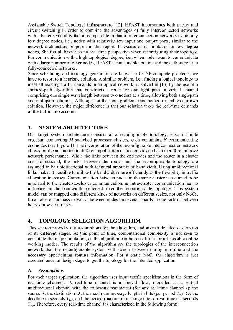
3. SYSTEM ARCHITECTURE Our target system architecture consists of a reconfigurable topology, e.g., a simple crossbar, connecting M switched processor clusters, each containing N communicating end nodes (see Figure 1). The incorporation of the reconfigurable interconnection network allows for the adaptation to different application characteristics and can therefore improve network performance. While the links between the end nodes and the router in a cluster are bidirectional, the links between the router and the reconfigurable topology are assumed to be unidirectional with identical amounts of bandwidth. Using unidirectional links makes it possible to utilize the bandwidth more efficiently as the flexibility in traffic allocation increases. Communication between nodes in the same cluster is assumed to be unrelated to the cluster-to-cluster communication, as intra-cluster communication has no influence on the bandwidth bottleneck over the reconfigurable topology. This system model can be mapped onto different kinds of networks on different scales, not only NoCs. It can also encompass networks between nodes on several boards in one rack or between boards in several racks.
4. TOPOLOGY SELECTION ALGORITHM This section provides our assumptions for the algorithm, and gives a detailed description of its different stages. At this point of time, computational complexity is not seen to constitute the major limitation, as the algorithm can be ran offline for all possible online working modes. The results of the algorithm are the topologies of the interconnection network that the reconfigurable system will switch between during run-time and the necessary appertaining routing information. For a static NoC, the algorithm is just executed once, at design stage, to get the topology for the intended application.
A. Assumptions For each target application, the algorithm uses input traffic specifications in the form of real-time channels. A real-time channel is a logical flow, modelled as a virtual unidirectional channel with the following parameters (for any real-time channel i): the source Si, the destination Di, the maximum message length in bits (per period TP,i) Ci, the deadline in seconds TD,i, and the period (maximum message inter-arrival time) in seconds TP,i. Therefore, every real-time channel i is characterized in the following form:

{ }iPiDiiii TTCDSCH ,, ,,,,= (1)
Additionally, the throughput demand Bi in bits per second of each real-time channel i is given by:
iP
ii T
CB,
= (2)
Also provided is the number of input and output ports on each router towards the topology, denoted as MAX_LINK, and information on whether the application demands full connectivity of the network. With full connectivity we mean that a path exists between all pairs of nodes, a fact which is of advantage if we, in addition to the real-time channels, have less well-defined communication in the system. Assuming priority support in the routers, such non real-time traffic can be given lower priority and will interfere slightly with the real-time traffic. However, this interference will be bounded to a single packet due to the nonpreemptiveness of a packet. For the intra-cluster traffic from the end nodes towards their first hop router, and vice versa, simply the link utilization is checked to ensure that there are no bottlenecks at this first and last hop of the communication path. However, they will still have to be included in the delay analysis, which is described later in the paper (Section 5). After this utilization check, the algorithm will not regard the links between end nodes and routers, but only the links between the routers over the reconfigurable topology.
B. Description The design approach for the algorithm has been to prioritize the allocation of physical links to connect pairs of nodes, with real-time channels between each other, demanding
Figure 1. Schematic system architecture
Router 11:N
Router M1:N
Router 21:N
Communicatingend nodes
Reconfigurable topology
Switch circuit to reconfigure
topology

high guaranteed throughput and/or short bounded delays. When multihop communication over the topology is needed, we prioritize shorter paths for such throughput and/or delay demanding communication. The algorithm works in three main phases: singlehop routing with link allocation, multihop routing with link allocation, and feasibility testing. Prior to the main phases, certain initializations are needed. For the case of the target application demanding full connectivity, a ring topology, incorporating all N nodes in the network, can be allocated, and, thereby, full connectivity can be guaranteed. In order to decide upon the sequence in which the logical real-time channels should be allocated, we introduce an individual weight Wi for each channel i. This weight is calculated by one of two weight functions, depending on the phase in which the channel is allocated. Details on those functions are given in the detailed description of the different phases below. 1) Phase 0 - Initializations (see Figure 2). As mentioned in Subsection A, the input to the algorithm comes in the form of real-time channel specifications. For the algorithm to know in which order to process the real-time channel demands during the upcoming Phase 1, the Initialization Phase, Phase 0, is started by calculating Wi for each channel i. A channel’s weight in Phase 1 is dependent on its throughput demand and its deadline, i.e., Ci, TD,i, and TP,i. Furthermore, this first weight function is solely aimed towards the singlehop routing case, where the length of a routing path is equal to three for every path. “Singlehop” in this context denotes thus only the hop over the reconfigurable topology, including neither the first hop from the sending node to the source router, nor the last hop between the destination router and the receiving node. Considering these facts, we define the following weight function s_wfcn for Phase 1:
Initialization 1. Calculate individual weight for all channels for ( i = 0 .. nbrOfChannels ) Wi = s_wfcn ( Ci, TD,i, TP,i ) end for 2. Group all channels into bundles according to their source-destination pair GS,D = ∪ {CHi | Si = S && Di = D, ∀ i} 3. Sort channels in every bundle into priority queues (highest bandwidth demand first) for all bundles
QS,D = priority_sort { GS,D } end for 4. Assign to bundles the summarized weight of all their channels for all bundles WS,D = Wi ∀ i | CHi ∈ GS,D end for 5. Sort all bundles into a priority queue (highest weight first) Qbundle = priority_sort (∪ { GS,D } )
∑i
Figure 2. Phase 0: Initialization algorithm

( )⎟⎟⎠
⎞⎜⎜⎝
⎛
⋅
==
iP
iD
iP
i
iPiDii
TT
MIN
TC
TTCwfcnsW
,
,
,,,
3,1
,,_ (3)
The minimum value function used in the denominator leads to one of two cases. If the period TP,i is shorter than a third of the deadline TD,i (due to a path length of three and the assumption of equal deadline partitioning; more on deadline partitioning in Section 5), then the only relevant factor for the weight of the link becomes its throughput demand (the numerator). On the other hand, if the period becomes longer than a third of the deadline, then even these two parameters become significant enough to be included in the weight calculation. In other words, the hop through the topology is assumed to be either utilization constrained or delay constrained. This is an approximating hypothesis based on the fact that, for the case when the period is equal or shorter to the per-hop deadline for all channels, only the aggregated utilization needs to be verified to be less or equal to 100% [14]. Those results have their origin from the field of processor task scheduling. After having assigned an individual weight to each logical real-time channel, the channels are grouped into bundles, each bundle GS,D containing channels with a specific source-destination pair (S,D). The channels in each bundle are sorted in a priority queue QS,D, with the channel that has the highest bandwidth demand getting the highest priority. By summarizing the individual weights Wi of all channels in one bundle, each bundle is assigned an individual weight WS,D. Lastly, all bundles are sorted in a priority queue Qbundle, giving highest priority to the bundle with maximum weight. 2) Ring Topology Allocation (see Figure 3). For the case of the target application demanding full connectivity, this specific phase of the algorithm is introduced. By allocating a ring topology, incorporating all N nodes in the network, full connectivity can be guaranteed. This phase starts out by pinpointing the logical channel with the highest bandwidth demand in the bundle with the highest summarized weight. This channel can be found at the first position in the priority queue QS,D that in its turn has the first position in Qbundle. The allocation of this first physical link L0 over the reconfigurable topology denotes the starting point of the ring, in the formal description (Figure 3) denoted as the set Ring. This path, as well as all the following paths during the entire algorithm, is stored in a routing table. Channel demands for which a path has been allocated are discarded from their priority queue. In order to continue the ring, the next bundle’s source node has to match the destination node of the last allocated link, and its destination must not be part of the ring topology already, unless it is the last link needed to close the ring. When finding this bundle, again the channel with the highest bandwidth demand in this bundle is picked and a new link, Lk, over the topology can be allocated. The demand is discarded from the queue and the new path information is stored in the routing table.

Figure 3. Ring topology allocation (For continuation see next page.)
Ring topology allocation* 1. Allocate a physical link for the logical channel with the highest bandwidth demand in the bundle with the highest summarized weight L0 ↢ CHj | (Bj = max(∪{Bj∀j | CHj∈(GS,D | WS,D = max(∪{ WS,D∀S,D})})) 2. Remove channel from its bundle GS,D = GS,D – {CHj} 3. Update routing table 4. Allocate all but the last remaining sections of the ring topology for ( k = 1 .. N – 2) 4.1. Find next bundle to connect 4.1.1. Allocate the physical link Lk ↢ CHj | (CHj∈GS,D | S = LD,k-1) && (Bj = max(∪{Bj∀j | CHj∈(GS,D | S = LD,k-1))}) 4.1.2. Remove channel from its bundle GS,D = (GS,D | S = Sj && D = Dj) – {CHj} 4.2. If no feasible bundle could be found in 4.1 4.2.1. Find subset of bundles not connected to the ring Gsub = {GS,D | S ∉ Ring && D ∉ Ring } 4.2.2. Find the bundle with the highest weight in the subset G = GS,D | WS,D = max (∪ {WS,D | GS,D∈Gsub} 4.2.3. Let the source of this bundle be the next destination LS,k+1 = S | (S ∈ (CHj | CHj ∈ G)) 4.2.4. Allocate the physical link Lk ↢ LS,D | (S = LD,k-1 && D = LS,k+1) 4.2.5. Directly allocate the next link k = k+1 Lk ↢ Chj | Chj ∈ G && (Bj = max ( ∪ { Bj ∀ j | CHj ∈ G ) } ) 4.2.6. Remove channel from its bundle GS,D = ( GS,D | S = Sj && D = Dj ) – {CHj} 4.3. If no feasible bundles could be found in 4.1. and 4.2. 4.3.1 Allocate a randomly chosen feasible link Lk ↢ random ( LS,D ∈ { LS,D | S = LD,k-1 && D ∉ Ring }) 4.4. Update routing table end for (For continuation see next page.)

Obviously, there is a possibility that no bundle exists that meets all demands. In this case, the algorithm searches freely in the subset Gsub that contains those bundles that do not have a source or destination already part of the incomplete ring topology. It chooses the bundle G (defined to be the one with the highest weight) in this subset Gsub, and uses its source node as the next destination. In the next step, the algorithm allocates a link LS,D from the last node already connected to the emerging ring to the source of G. At the same time, it has already found the bundle with the highest weight for the next section, namely bundle G, and can therefore continue directly by allocating a path for the channel demand with the highest throughput demand in G. The algorithm continues until the entire ring is closed. Obviously, for the last section, both the source and the destination node are known, and therefore only one bundle is possible for this section of the ring, independent of its weight. If at any time during the ring allocation algorithm there is no longer any bundle available, i.e., the number of bundles is smaller than the number of sections needed to connect all nodes in a ring, the algorithm randomly chooses the next destination of each section, avoiding nodes that are already part of the ring (except for the last section). The Ring Topology Allocation Phase is concluded by updating the weights of the bundles, i.e., summarizing the weights of the remaining real-time channels, and resorting Qbundle according to the new weights. 3) Phase 1 - Singlehop routing with link allocation (see Figure 4). After having initiated the necessary parameters in Phase 0 and fulfilled the possible demand for full connectivity in the network, the algorithm enters Phase 1. During this
Figure 3. Ring topology allocation (continued)
Ring topology allocation* (continued) 5. Allocate the last link to close the ring 5.1. Find a bundle to connect 5.1.1. Allocate the physical link Lk ↢ CHj | CHj ∈ (GS,D | S ∉ Ring && D ∉ Ring) 5.1.2. Remove channel from its bundle GS,D = ( GS,D | S = Sj && D = Dj ) – {CHj} 5.2. If no feasible bundle could be found in 5.1. 5.2.1. Allocate the physical link Lk+1 ↢ LS,D | S = LD,k && D = LS,0 5.3. Update routing table 6. Repeat Initialization step 4 7. Repeat Initialization step 5
*Within the limits of this specification, the source and the destination associated with any link k are denoted LS,k and LD,k.

phase, the algorithm routes singlehop paths, and when necessary allocates new physical links over the topology. The algorithm sequentially tries to allocate all logical real-time channels contained in bundle G (still defined to be the one with the highest weight) through direct links over the topology. The channels are treated according to bandwidth demand, with the highest demand getting the highest priority. After having allocated all channels in one bundle, the algorithm treats the bundle with the next highest weight in the same fashion. When allocating a path for a channel, the algorithm first examines if a link already exists between the source and destination router of the investigated channel and examines this link’s capacity to check if the throughput demands of the real-time channel can be met. The sum of the throughput demands of all logical real-time channels (including the one under investigation) over the same physical link must not exceed the maximum bit rate of that link. If it does not, the additional channel can be allocated on the existing link. (More details about the utilization constraint will follow in Section 5.) In case there is not enough capacity left on the link, the algorithm checks for the possibility to allocate a new physical link, parallel to the recently examined, using unallocated output ports at the source router and unallocated input ports at the destination router. An important point is reached when the algorithm no longer can find a singlehop path for a channel. When it detects the first channel that needs a path that crosses the reconfigurable topology several times, i.e., a multihop path, the algorithm only tries to allocate the remaining channel demands in the current bundle as singlehop paths before terminating Phase 1. Then it will enter into Phase 2 to start with multihop routing. In case all real-time channels could be allocated as singlehop paths in Phase 1, the algorithm continues directly with the feasibility check in Phase 3. 4) Phase 2 - Multihop routing with link allocation (see Figure5). In the multihop routing phase of the algorithm, the prioritization is solely based on the deadlines specified in the real-time channel demands and the concept of bundles is no longer used. The decision of making the priority solely dependent upon the end-to-end deadline of the real-time channel is based on the approximating assumption of the uniformity of all links, resulting into longer delays over paths with a larger number of hops. The new individual weight Wi of all remaining channels is calculated by the new weight function m_wfcn, which has TD,i as its only input parameter:
iDiDi T
TwfcnmW,
,1)(_ == (4)
All individual channels are sorted in a priority queue Qchannel, with the highest weight and, by that, the shortest relative deadline getting highest priority. Each routing path R is found by an unweighted shortest path algorithm, related to Dijkstra’s algorithm (For details on Dijkstra’s algorithm, see, e.g., [2] or [15].), and with all link costs being equal to one. This leads to a routing algorithm with a hop-based cost metric, and, therefore, the shortest path signifies the path with the smallest number of hops between Si and Di. For each real-time channel demand, the shortest path algorithm searches a route through the partly allocated network, trying primarily to use the existing links, unless their remaining capacity is too small to cope with the throughput demand of the channel currently under consideration. Only secondarily new, unallocated, links are set up.

Figure 4. Phase 1: Singlehop routing with link allocation
Singlehop routing with link allocation 1. Indicate the start of phase 1 phase1 = true for ( i = 0 .. nbrOfBundles ) 2. Find the remaining bundle with the highest weight G = GS,D | WS,D = max (∪ { WS,D ∀ S,D } 3. Try to allocate all channels in this bundle highest bandwidth demand first for ( j = 0 .. nbrOfChannelsInG)
if ( ( LS,D | S = Sj && D = Dj) ∈ Topology)
3.1. Check utilization if (capacityOfLS,D + Bj > maxCapacity )
3.1.1. Allocate path over existing link L ↢ CHj | CHj ∈ G 3.1.2. Remove channel from its bundle GS,D = ( GS,D | S = Sj && D = Dj ) – {CHj} G = ( GS,D | S = Sj && D = Dj ) 3.1.3. Update routing table end if
else 3.2. Check for empty ports at source and destination router
if ( numberOfUnallocatedPortsAtSourceRouter > 0 && numberOfUnallocatedPortsAtDestinationRouter > 0 )
3.2.1. Allocate link and path over new link L ↢ CHj | CHj ∈ G 3.2.2. Remove channel from its bundle GS,D = ( GS,D | S = Sj && D = Dj ) – {CHj}
G = ( GS,D | S = Sj && D = Dj )
3.2.3. Update routing table else 3.2.4. Indicate entry into conclusion of phase 1 phase1 = false end if
end if end for 4. Check if phase 2 should be entered if (phase1 = false) 4.1. No more bundles will be checked break; end if end for 5. Stop Phase 1 6. Start Phase 2

Multihop routing with link allocation 1. Indicate the start of phase 2 phase2 = true 2. Calculate individual weight for all remaining channels for ( i = 0 .. nbrOfChannels ) Wi = m_wfcn ( TD,i ) end for 3. Sort channels into a priority queue (highest weight, i.e. shortest relative deadline, first) Qchannel = priority_sort (∪ { CHi } ) 4. Shortest path routing 4.1. Route all channels for ( j = 0 .. nbrOfChannels ) 4.2. Find shortest path by breadth-first search
R = shortestPath ( CHj )
4.3. Check if path exists if (R exists) 4.3.4. Check if new physical links have to be allocated
while (new link allocation necessary) 4.3.4.1. Allocate new physical links over topology
Topology = Topology + newLink end while
4.3.5. Allocate path L ↢ R
4.3.6. Update routing table else 4.3.7. Terminate unsuccessfully phase2 = false
break; end if
end for 5. Check if routing phase was successful if (phase2 = true) 6. Stop phase 2 7. Start phase 3 else 8. Terminate the algorithm end if
Figure 5. Phase 2: Multihop routing with link allocation

Since there might exist unallocated links in the system, the possibility of creating a shorter path via those completely free links has to be considered. Being an unweighted shortest path algorithm, our algorithm tries to find the path using a breadth-first search, starting at the source node, and terminating on the first occurrence of the destination. A breadth-first search visits all children of a node, places them in a pending first-in first-out (FIFO) queue, and marks the parent node as “visited”. This procedure is repeated for all nodes in the pending queue until all pending nodes have been visited or the given destination has been found. In our slightly modified version of the breadth-first search, this procedure is extended to also take into consideration all unallocated links, which implies that if a node has a spare (unallocated) link, any other node in the system could be a potential child. Practically this means that when a node has at least one free output port, all unvisited nodes with at least one free input port are added to the pending queue. The details of the standard unweighted shortest path routing have been discarded from the formal description of the algorithm. The difference in our modified version, which is the content of the pending queues in the breadth-first algorithm, would not be visible unless a more fine-grained specification was provided. When the algorithm has routed all logical channels, the routing table and the topology are provided as input for the feasibility test in Phase 3. Unallocated ports are left untreated in the current version of the algorithm. In case a path could not be found for all channels, the algorithm is terminated, as no suitable topology could be found for the given traffic specifications, otherwise the algorithm proceeds further to the feasibility check (Phase 3). 4) Phase 3 - Feasibility testing. A feasibility test has been added to verify that all real-time demands can be met. In case of a positive outcome, our algorithm provides as output the recommended network topology and a routing table belonging to the traffic demands. Otherwise, no suitable topology for the target application could be found. The theory of the feasibility analysis and the details of its application in our algorithm are given in the next section.
5. FEASIBILITY ANALYSIS In order to be able to determine the performance characteristics for the hard real-time traffic over an arbitrary topology, this section provides a throughput guarantee and delay bound analysis. Due to the assumption of earliest deadline first (EDF) scheduling in all end nodes and intermediate routers, the feasibility analysis suggested in [16] can be used in a similar manner for our network, as described below. When comparing the feasibility analysis of communication with the feasibility analysis in processor task scheduling, real-time channels correspond to periodic tasks, where a physical link in the network can be seen as a processor and the maximum message length in our traffic specification is the equivalent to the worst-case execution time Ci for the task i in the original analysis. For the description of the feasibility check, a number of concepts need to be defined. • The utilization U of periodic real-time traffic is defined as
∑ ⎟⎟⎠
⎞⎜⎜⎝
⎛=
i iP
i
TC
U,
(5)
where TP,i denotes the period (minimum message inter-arrival time) of traffic over the logical channel i. • The hyperperiod HP is the least common multiple of all periods of a periodic task
set, i.e., the length of time from when all tasks' periods start at the same time, until they start at the same time again.

• The busyperiod BP is any interval within HP in which the resource, in our case the link, is not idle.
• The traffic demand on the network corresponds to the processor demand in a real-time system and is defined by the workload function h(t). h(t) is calculated as the sum of Ci for all message instances of all real-time channels with an absolute deadline less then or equal to a point in time t, where t signifies the number of time slots elapsed since the beginning of HP. h(t) is computed as follows [17].
( ) ( )i
tT iP
iD CT
Ttth
iD
⋅⎟⎟⎠
⎞⎜⎜⎝
⎛
⎥⎥⎦
⎥
⎢⎢⎣
⎢ −+= ∑
≤, ,
,1 (6)
In our algorithm, the feasibility analysis is conducted for each physical link, which means that the total end-to-end deadline has to be partitioned into local singlehop deadlines that are valid for a single hop instead. For the matter of simplicity we have chosen an even distribution of the deadline over the entire path, i.e., the local deadline di corresponds to the end-to-end delay bound TD,i divided by the number hops NoHj that the relevant path j consists of.
j
iDi NoH
Td ,= (7)
Obviously, there are more favourable deadline partitioning schemes, but as for now they are outside the scope of this report. However, this type of feasibility analysis assumes fully preemptive tasks. In an interconnection network, packets normally cannot be preempted, and consequently the possibility of further delay has to be considered. Therefore, we define the blocking time BT, which denotes the maximum blocking time that one (possibly lower-priority) packet can introduce to the system, i.e., BT equals the transmission time of a maximum size packet. This compensation results in a further shortening of the local delay bound.
BTdd ii −=' (8) This means that the workload function is remodelled as follows.
( ) ( )i
td iP
i CT
dtth
i
⋅⎟⎟⎠
⎞⎜⎜⎝
⎛
⎥⎥⎦
⎥
⎢⎢⎣
⎢ −+= ∑
≤' ,
'
1 (9)
While keeping U ≤ 1 is a necessary condition for being able to feasibly schedule periodic tasks by EDF [17], a second constraint was introduced in [17] to ensure the feasibility of the system when adding a new task or channel:
( ) ttth ∀≤ (10) This restriction introduces a high computational complexity, but the number of instances of evaluation can be reduced to the number of integer time values during an interval upper bounded by BP1, the first BP in the first HP of the schedule where all periods start at time zero. In other words,

{ }U 1 ,, ...2,1,0:=
=+⋅∈i iDiP mTTmt (11)
where
[ ]1;1 BPt ∈ (12) Again, this has to be adapted to our hop-by-hop calculations by exchanging the end-to-end delay bound TD,i with the local delay bound di, which results in the following points in time having to be checked.
{ }U1
, ...2,1,0:=
=+⋅∈i
iiP mdTmt (13)
In our case of nonpreemptive communication, the local delay bound, di, further has to be exchanged for di’ because of the possibility of blockage, which results in the following set:
{ }U1
, ...2,1,0:=
=+⋅∈i
iiP mdTmt (14)
where
[ ]1;1 BPt ∈ (15) The upper and lower boundaries of the interval for t stay unmodified. In order for the whole path to be accepted, all contained hops must be found feasible.
6. CASE STUDY The topologies generated by the proposed algorithm are evaluated by comparing the network efficiency of the generated topologies with that of a 2D-torus, a standard topology for high-performance computer architectures. In a 2D-torus, each node has four neighbours and the topology has wrap-around edges. The efficiency of a given topology is defined as the pair (Unet |L|), where Unet denotes the total network utilization, i.e., the sum of the utilization Ui for all links i (Equation 16), and |L| is the number of physical links used, i.e., the sum of the ceiling function of the utilization Ui for all links i (Equation 17).
∑=i
inet UU (16)
⎡ ⎤∑=i
iUL (17)
In evaluating the efficiency of the different solutions, a lower value of Unet signifies a more energy efficient topology since it consumes less of the total network resources. In cases of similar values of Unet, a lower value of |L| indicates a more hardware efficient topology, since this topology has more efficiently allocated links, i.e., a smaller number of links is needed as the capacity of the existing links is used to a higher degree. Even though it can be argued that it is better to use all available resources, a larger number of links with lower utilization could be an indication that the algorithm has chosen longer paths than necessary. In other words, a low value of |L| indicates an efficient algorithm

that can lead to a higher possible amount of guaranteed real-time traffic in case this is requested. In order to demonstrate the algorithm’s applicability for use cases with different traffic patterns, the algorithm has been tested with two types of radar signal processing chains. Case 1 is dominated by intense one-to-many and many-to-one communication, while Case 2 contains more pipelined traffic and just a minor amount of one-to-many and many-to-one transmissions. A detailed specification of the traffic demands is given in Figure 6 and Figure 7. The layout for the 2D-torus configuration was chosen to be 3x4 nodes. Although a 2x6 configuration could have been used, the 3x4 configuration was considered to be more flexible and more likely to be actually used in practice. The mapping of the nodes and links of the 2D-torus were done manually, keeping |L| at a minimum. In order to be able to compare the efficiency of the generated topologies directly with the 2D-torus, the experiments were carried out with the MAX_LINK constraint (maximum number of input and output ports for each node) for the generated topologies being set to four.
Figure 6. Case 1: Corner turn traffic demands
G
B
D
H
A IE L
K
C
F
J
2
1.33
2
1.33
0.66
0.66
0.133
0.133
0.133
0.133
0.13
3
3x5x0.2

Figure 8. Case 1: Topology and traffic allocation produced as a result of the proposed algorithm
G
B
D
H
A IE L
K
C
F
J
2
1.33
2
1.33
0.66
0.66
0.133
0.133
0.133
0.26
63x3x0.2
0 .33
0.4
3x0.4
Figure 7. Case 2: Pipeline traffic demands
BA
D
C
E F G
I
H
J
K
L2
1
1
1
12 2
4x1 4x0.25

The proposed algorithm managed to find feasible solutions within the specified requirements for both cases. As seen in Table I and Figures 8-11, the proposed algorithm generated more efficient topologies than a 2D-torus in both cases, and in neither of the cases, the solutions failed the feasibility test. Using the proposed algorithm and a reconfigurable topology, the experiments show a 10-30 % reduction of the number of links used and a 20-40 % reduction of the used network bandwidth, compared to when using a manually configured 2D-torus. Practically this means that the reconfigurable topologies have more spare resources and can therefore accept a higher load of real-time traffic in case that would be requested. The difference is more noticeable in Case 1 because of the substantial number of one-to-many and many-to-one transmissions. However, even for the pipelined structure of Case 2, the proposed algorithm found a more efficient solution. This depends upon the fact that several transmissions to the same destination require more than one link, and have to be routed over a multi-hop path in a 2D-torus. The reconfigurable topology, however, has the opportunity for the allocation of several parallel links between node pairs. In the case of one-to-many or many-to-one communication where the number of parallel transmissions exceeds four, the usage of multi-hop paths is inevitable due to the MAX_LINK constraint, independent of the topology. However, a reconfigurable topology gives the option of a more flexible path allocation compared to the 2D-torus.
Figure 9. Case 1: Topology and traffic allocation mapped onto a 2D-torus
A C F I
B E H L
D G J K
Link LoadB-E 0.86B-L 0.33C-E 0.66C-F 0.2C-G 0.53D-B 0.2D-K 0.8E-G 0.8E-H 0.4F-H 0.533F-J 0.4G-J 0.863
Link LoadH-L 0.666I-F 0.133J-F 0.33J-H 0.2J-K 0.996K-D 0.33K-I 0.2K-J 0.4K-L 0.729L-I 0.4L-K 0.33
All remaining indicated links have a load of 1.

Figure 11. Case 2: Topology and traffic allocation mapped onto a 2D-torus
A F G H
C E L I
B D K J
Link LoadG-L 0.25H-J 0.25I-L 0.75J-I 0.5K-L 0.25K-J 0.25L-K 0.25
All remaining indicated links have a load of 1.
Figure 10. Case 2: Topology and traffic allocation produced as a result of the proposed algorithm
BA
D
C
E F G
I
H
J
K
L2
1
1
1
12 2
4x1 4x0.25

7. CONCLUSION AND FUTURE WORK It is clear that the SoC/NoC community is in need of more powerful communication networks compared to the commonly used bus hierarchies, both in terms of flexibility and efficiency. This makes a dynamically reconfigurable topology a well-suited alternative. However, to fully utilize the potential of a dynamic topology, efficient tools such as the algorithm presented in this report, are needed. The advantages of using reconfigurability in a NoC are obvious. The topology can be adapted to different applications, or different modes of applications, and even different traffic patterns in one single application. The proposed topology allocation algorithm has been shown to produce solutions that outperform a manually configured traditional topology for high-performance networks. In comparison with a traditional 2D-torus, the results proved that the aggregated network utilization could be decreased with approximately 40 % by using the proposed algorithm. Possible extensions of the current version of the algorithm include taking into account system demands for energy efficiency and fault tolerance. In addition, a more advantageous deadline partitioning could be used to further improve network performance. The next step of the algorithm development is the integration of the feasibility analysis in earlier phases of the actual algorithm and to use this additional information when generating the topology in order to be able to guarantee the timely treatment of hard real-time traffic. Furthermore, there are plans for a more holistic approach to system design.
REFERENCES [1] W. J. Dally and B. Towles, “Route Packets, Not Wires: On-Chip Interconnection
Networks”, 38th Conference on Design Automation (DAC ‘01), June 2001, pp. 684-689.
[2] M.T. Goodrich and R. Tamassia, Algorithm Design. J. Wiley & Sons, NY, USA, 2002.
[3] J. M. García and J. Duato, “An Algorithm for Dynamic Reconfiguration of a Multicomputer Network”, Proceedings of the 3rd IEEE Symposium on Parallel and Distributed Processing, December 1991, pp. 848-855.
[4] W. H. Ho and T. M. Pinkston, “A Methodology for Designing Efficient On-Chip Interconnects on Well-Behaved Communication Patterns”, Proceedings of the 9th International Symposium on High-Performance Computer Architecture (HPCA-9 ‘03), February 2003, pp. 377-388.
Table 1. Total utilization in the network and total utilization of links
|L|**Unet*
35
12,4 28
21,4
1916
3229,75Case 2:Pipeline
Case 1:Corner turn
2D-torus
Generated topology
2D-torus
Generated topology
*Results are given in % of maximum link utilization.**Results are given in number of used links.

[5] D. Bertozzi, A. Jalabert , S. Murali, R. Tamhankar, S. Stergiou, L. Benini, and G. De Micheli, “NoC Synthesis Flow for Customized Domain Specific Multiprocessor Systems-on-Chip”, IEEE Transactions on Parallel and Distributed Systems, vol. 16, no. 2, February 2005, pp. 113-129.
[6] S. Murali and G. De Micheli, “SUNMAP: a Tool for Automatic Topology Selection and Generation for NoCs”, Proceedings on the 41st Design Automation Conference (DAC ‘04), June 2004, pp. 914-919.
[7] S. Murali, L. Benini, and G. de Micheli, “Mapping and Physical Planning of Networks-on-Chip Architectures with Quality-of-Service Guarantees”, Proceedings of the Asia and South Pacific Design Automation Conference (ASP-DAC ´05), vol. 1, January 2005, pp. 27-32.
[8] K. Srinivasan, K. S. Chatha, and G. Konjevod, “Linear Programming Based Techniques for Synthesis of Network-on-Chip Architectures”, Proceedings of the IEEE International Conference on Computer Design: VLSI in Computers and Processors (ICCD ’04), October 2004, pp. 422-429.
[9] A. Hansson, K. Goossens, and A. Rădulescu, “A Unified Approach to Constrained Mapping and Routing on Network-on-Chip Architectures”, Proceedings of the 3rd
International Conference on Hardware/Software Codesign and System Synthesis (CODES+ISSS’05), September 2005, pp. 75-80.
[10] S. Murali, P. Meloni, F. Angiolini, D. Atienza, S. Carta, L. Benini, G. De Micheli, and L. Raffo, “Designing Application-Specific Networks on Chips with Floorplan Information”, Proceedings of the International Conference on Computer-Aided Design (ICCAD’06), November 2006, pp. 355-362.
[11] J.M. García, and J. Duato, “An Algorithm for Dynamic Reconfiguration of a Multicomputer Network”, Proceedings of the 3rd IEEE Symposium on Parallel and Distributed Processing, December 1991, pp. 848-855.
[12] J. Shalf, S. Kamil, L. Oliker, and D. Skinner, “Analyzing Ultra-Scale Application Communication Requirements for a Reconfigurable Hybrid Interconnect”, Proceedings of the ACM/IEEE Supercomputing Conference (SC ‘05), November 2005, pp. 17-29.
[13] K. Lee and M. Shayman, “Single and Multipath Logical Topology Design and Traffic Grooming Algorithm an IP over WDM Networks”, Proceedings of the 12th International Conference on Computer Communications and Networks (ICCCN ’03), October 2003, pp. 59-64.
[14] C. L. Liu and J. W. Layland, “Scheduling Algorithms for Multiprogramming in Hard Real-Time Traffic Environments”, Journal of the Association for Computing Machinery, vol. 20, no. 1, January 1973, pp. 46-61.
[15] F. Halsall, Data Communications, Computer networks and Open Systems. (4th ed.), Addison-Wesley, Essex, UK, 1996.
[16] H. Hoang and M. Jonsson, “Switched Real-Time Ethernet in Industrial Applications - deadline partitioning”, The 9th Asia-Pacific Conference on Communication (APCC ‘03), vol. 1, September 2003, p. 76-81.
[17] J. A. Stankovic, M. Spuri, K. Ramamritham, and G. C. Buttazzo, Deadline Scheduling for Real-Time Systems - EDF and Related Algorithms. Kluwer Academic Publishers, Boston, MA, USA, 1998.