Embed Size (px)
Citation preview

ALDOT Bridge Bureau Structures Design and Detailing Manual – January 1, 2008
1
ALDOT
Bridge Bureau
Structures Design and Detail Manual

ALDOT Bridge Bureau Structures Design and Detailing Manual – January 1, 2008
2
Purpose and Scope of This Manual The AASHTO Standard Specifications for Highway Bridges are the basic documents guiding all
design. This manual contains specific design and detailing criteria policies expressed by the
Bridge Bureau and is intended:
1. to provide interpretation and consistency in the application of the AASHTO
specifications;
2. to encourage the uniform preparation of plans and specifications, and;
3. to be followed on projects under the authority or oversight of the Bridge Bureau
unless exceptions are approved by the State Bridge Engineer.
Exceptions, based on sound engineering principles and judgement, are expected.
Structural plans and specifications must clearly communicate the design concept and detail
requirements of each project. Efficiency, economy, constructability, advances in technology,
maintainability, and appearance are elements the designer must consider in applying the
AASHTO specifications and these guidelines. Safety must be an integral part of each of these
elements.
This manual will be continually updated as revisions and improvements are warranted. Any
questions, comments, concerns, and/or suggestions are welcomed and should be submitted to:
John F. Black, P.E.
Bridge Engineer
1409 Coliseum Blvd.
Montgomery, AL 36130-3050

ALDOT Bridge Bureau Structures Design and Detailing Manual – January 1, 2008
3
Specifications and Drawings
Standard Specifications:
The Department's Standard Specifications for Highway Construction and Supplemental
Specifications (Specifications) provide the controls for the materials and construction of all
projects except as modified by the Plans and Special Provisions. Structural plans shall be
prepared with notes and details that are generally in accordance with these specifications. If a
plan detail or note is not covered by a Specification, then a special provision shall be provided.
The order of control is; plans shall govern over Standard Specifications and Supplemental
Specifications, and Special Provisions shall govern over Plans. Copies can be obtained from the
Office of the Proposals Engineer for a small fee to cover printing costs.
Standard Drawings:
The Department has compiled a set of drawings, Special and Standard Highway Drawings
(Standards), for use on all projects. This set of drawings is updated and printed annually and a
copy may be obtained from the Office of the Proposals Engineer for a small fee to cover printing
costs.
The Standards contain several miscellaneous drawings such as the standard bridge general notes,
standard bridge details, retaining wall details, precast bridge details, and miscellaneous culvert
details. These drawings when applied to a specific project shall be noted on the “Bridge General
Plan and Elevation” sheet or “General Notes, Estimated Quantities, and Required” sheet as
appropriate.

ALDOT Bridge Bureau Structures Design and Detailing Manual – January 1, 2008
4
Guide for Developing Construction Plans (GDCP) The Department has developed a step by step procedure to direct its designers through the typical
project design process. The GDCP provides steps for the coordination between the various offices
of the Department. A copy of the GDCP may be obtained by contacting the Roadway Design
Engineer of the ALDOT Design Bureau.

ALDOT Bridge Bureau Structures Design and Detailing Manual – January 1, 2008
5
Bridge Consultants Under Direct
Contract with the Department The State Bridge Engineer is responsible for negotiating fees with consultants selected to assist
the Department in preparing structural designs/bridge contract drawings. The State Bridge
Engineer is also available to assist in negotiating fees prepared by consultants under direct
contract with counties and cities. The State Bridge Engineer is responsible for providing
structural design and detailing guidelines to the consultant and for approving structural plans and
specifications prepared by the consultant.
The Bridge Bureau has four design sections. Each of these sections shares the responsibility of
oversight of consultant design and plan preparation activities. A contact person will be designated
for each consultant project. Instructions given in this manual for consultants only apply to those
consultants under direct contract with the Department, counties, and cities.
Consultants shall follow the guidelines in this manual unless the State Bridge Engineer gives
exception approval in writing. If a conflict arises between this manual and an existing set of
plans provided to the consultant for general information, this manual shall govern.
It is the consultant’s responsibility to prepare a complete design in accordance with these
guidelines. An independent structural check of bridge plans completed by the consultant,
including a check of design stress analysis and a check of detailing and drafting of completed
plans shall be made. Competent personnel other than those performing the original design,
detailing, or drafting shall make this independent check. A statement certifying that the required
independent check has been performed shall be placed on the first bridge project sheet and signed
by the structural designer of record and reviewing engineer.
If the need arises to establish design and detail criteria not specified in this manual, the consultant
shall recommend the needed criteria to the State Bridge Engineer for approval.
The final project plans shall be signed and sealed by a professional engineer employed by the
consultant and registered in the State of Alabama.

ALDOT Bridge Bureau Structures Design and Detailing Manual – January 1, 2008
6
Design of Federal-aid Bridge and Structure Projects A. Project Involvement by FHWA is based on the Safe, Accountable, Flexible, Efficient
Transportation Equity Act: A Legacy for Users (SAFETEA-LU) and differs according to
highway classification and funding. The following summarizes the Alabama Department
of Transportation and FHWA agreement for review of bridges and structures included in
Federal-aid projects:
1. Interstate – All projects involving bridges on or over the interstate except Interstate
bridge widening projects that add one travel lane and full width shoulders where the
estimated bridge construction cost is less than $5 million.
2. National Highway System (NHS) – All projects where estimated bridge construction
cost exceeds $5 million.
3. Non-National Highway System – All projects where estimated bridge construction
cost exceeds $5 million.
4. Special Projects - as specifically identified in SAFETEA-LU, where estimated
bridge construction cost exceeds $5 million.
5. Appalachian Development (APD) – All projects.
6. Bridge Replacement & Rehabilitation Projects (HBRRP) - Projects will be handled
according to the above guidelines based on its location on or off the NHS, except, the
Department can ask for FHWA involvement on any project, at any time, and/or
during any phase.
7. Annually, FHWA will review a sample of non-involvement federal aid bridge
projects to ensure compliance with federal regulations.
8. The State Bridge Engineer will submit a yearly report of the bridge construction unit
cost data for new and replaced highway bridges constructed with Federal funds. The
bridge construction unit cost data reported for each fiscal year will be used in the
funding apportionment process as described in Title 23, U.S.C. Section 144(e).
9. The Department will adhere to the requirements of AASHTO and the ALDOT
Structures Design and Detail Manual in designing all new and replaced highway
bridges constructed with Federal funds. The ALDOT Structures Design and Detail
manual is considered a supplementary document to the AASHTO Specifications and
will be maintained by the State Bridge Engineer. Revisions and additions to this
supplementary document will require FHWA approval.
10. The Department will maintain and make use of Special and Standard Highway
Drawings that have been approved by FHWA. Each of these Special and Standard
Drawings will be reviewed and approved on an annual basis by FHWA.
B. Project involvement by FHWA for unusual bridges and structures on Interstate highways
will require approval by the FHWA Washington office. This policy applies to
rehabilitation projects as well as new structures.

ALDOT Bridge Bureau Structures Design and Detailing Manual – January 1, 2008
7
Unusual bridges are those that FHWA determines to have:
Difficult or unique foundation problems
New or complex designs with unique operational or design features
Exceptionally long spans (greater than 500 feet)
Design procedures that depart from currently recognized acceptable practices
Examples of unusual bridges include cable-stayed, suspension, arch, segmental concrete,
movable, or truss bridges.
Unusual structures are tunnels, geotechnical structures featuring new or complex wall
systems or ground improvement systems, and hydraulic structures that involve complex
stream stability countermeasures or design techniques that are atypical or unique.
Preliminary documents to be submitted to FHWA Washington Office should include
preliminary design plans and supporting data along with Division’s review comments
and recommendations. Supporting information should include:
Bridge/structures related environmental concerns and suggested mitigation
measures.
Studies of bridge types and span arrangements.
Approach bridge span layout plan and profiles sheets.
Controlling vertical and horizontal clearance requirements.
Roadway and geometry design specifications used.
Any special design criteria.
Special provisions that are applicable to the project.
Cost estimates.
Hydraulic and scour design studies/reports showing predictions and related
mitigation measures.
Geotechnical studies/reports.
Proposed substructure and foundation types.

ALDOT Bridge Bureau Structures Design and Detailing Manual – January 1, 2008
8
Preliminary Design Criteria
Geometrics: The AASHTO geometric design manual provides the recommended geometric design criteria
used to determine roadway widths, alignment, stage construction, and vertical and horizontal
clearances. The criteria vary according to the functional classification of the highway. The Design
Bureau/Division/County is responsible for establishing the geometric requirements of each
project and preparing roadway plans. Input from the bridge designer is needed where minimum
vertical clearances are required. The following typical geometric controls are provided for the
convenience of the bridge designer:
Bridge Clearances over:
1. Floodplains – (See “Hydraulics” section of this document)
2. Navigable Waterways – (See “Coast Guard Permits” section of this document)
3. Railroads - See “Structures over Railroads” section of this document)
4. Highways - Clear zone requirements vary with design speed and other site
conditions and may require different horizontal clearances. The following clearances
typically apply to most routes:
a. Interstate and Primary Routes
Vertical - 17' (18' desirable for sign & pedestrian bridges)
*Horizontal - 30' desirable from edge of outside lane to face of
bridge pier
20' desirable from edge of auxiliary lane to face
of bridge pier
* (Whenever possible, the front face of bridge piers for grade
separation structures should be located a minimum of 3 feet
behind the back edge of ditch)
b. Secondary Routes
Vertical - 17' desirable
14' absolute minimum
Horizontal - 30' desirable

ALDOT Bridge Bureau Structures Design and Detailing Manual – January 1, 2008
9
Bridge Alignment:
Horizontal and vertical profile shall match grades provided in roadway plans.
Bridge Widths:
The bridge width from barrier face to barrier face generally matches the roadway section
with paved shoulders as provided in the roadway plans. This includes existing bridges to
be widened, except Interstate bridges. Existing Interstate bridges to be widened will be
widened symmetrically based on the larger shoulder. Additional bridge width may be
required for traffic handling during construction.
The following widths are typically used for new bridges:
25' - Single lane ramp (shoulders 4' inside / 5' outside)
38' - Two lane ramp
40' - Two lane dual bridges (shoulders 6' inside / 10' outside)
44' - Two lane (two way)
56' - Three lane dual bridges
Note: For structures with three or more lanes in one direction, the gutter to gutter
dimension shall be calculated as follows:
(Lane width) x (Number of lanes) + 20’ (2 – 10 foot shoulders)
Example: Three 12 foot lanes = (12)(3) +20 = 56’ gutter to gutter
Stage Construction:
When stage construction of the roadway is required, the Bridge Designer shall coordinate
the design of the stage construction for the bridge with the Design Bureau, Division
Office, or Roadway Design Consultant as appropriate. This is required to ensure that the
traffic control plan and the bridge plans are in agreement.

ALDOT Bridge Bureau Structures Design and Detailing Manual – January 1, 2008
10
Hydraulics The Bridge Bureau Hydraulic Engineer is responsible for:
1. Preparing the Hydraulic Report with the hydrologic and hydraulic design used to size the
bridge waterway opening.
2. Locating the proposed waterway piers.
3. Performing the scour design using the current edition of the FHWA Highway Engineer
Circular 18.
The results of the scour design shall be considered in determining the foundation type and span
length and shall be provided to the Geotechnical Engineer. The Bridge Hydraulic Engineer shall
coordinate the design of bridges in Regulatory Floodways with the Federal Emergency
Management Agency (FEMA) in accordance with the floodplain management regulations.
General guidelines:
1. For non-navigable stream crossings, a minimum of 2 feet of freeboard above design flood
stage (measured from the low point of the superstructure) shall be provided. Exceptions
to this policy shall require approval of the State Chief Engineer.
2. The 50-year flood shall be used for establishing the profile on state and interstate routes.
The 25-year flood shall be used for establishing the profile on secondary routes.
Exceptions to this policy will require approval of the State Bridge Engineer.
3. Calculated scour shall be considered in design of the substructure as recommended by
the Hydraulic and Geotechnical Engineers.
4. In accordance with FHWA Hydraulic Engineering Circular No. 18 guidelines, the top of
footing for pile footing foundations should be located below the streambed a depth equal
to the estimated long-term degradation and contraction scour depth. All exceptions to
this requirement shall have prior approval of the Bridge Engineer. Influence such as
corrosion due to exposed piling, debris collection on piling, and unbraced pile length
(exposed pile below footing + depth to fixity) shall be considered in the design of pile
footing foundations whenever the top of footing is to be constructed above the estimated
long-term degradation and contraction scour depth.
5. All foundations shall have a minimum factor of safety of 1.1 (ultimate load) under super
flood (500-year event) conditions.
6. The hydraulic designer shall calculate overtopping flood and this information shall be
provided to the roadway designer to be included on the roadway plan and profile sheet at
the appropriate location.
7. Four-inch diameter scuppers shall provide deck drainage unless otherwise directed by the
Bridge Hydraulic Engineer. The scuppers shall be spaced at 5' (maximum) centers along
both gutterlines in a crowned section and 4' along the lower gutterline in a superelevated
section unless otherwise directed by the Bridge Hydraulic Engineer. Scuppers shall be
omitted over pier caps, roadway lanes, and railroad roadbeds. Larger scuppers or deck
drain inlets may be required if the above design is not adequate or if a closed system is
required.

ALDOT Bridge Bureau Structures Design and Detailing Manual – January 1, 2008
11
8. Rainfall spread on the bridge (spread from gutterline) shall be limited to the shoulder area
during the design storm. The design storm shall be the 10 year frequency storm for
bridges on county routes. For all other routes, the design storm shall be the 10 year
frequency except that the 50 year frequency storm shall be used for bridges located where
the low point of a sag vertical curve occurs on the bridge. The 50 year frequency shall be
used in the sag location. Any exceptions to this policy shall require the approval of the
Bridge Engineer.

ALDOT Bridge Bureau Structures Design and Detailing Manual – January 1, 2008
12
Layouts The preliminary layout is developed by the bridge designer in coordination with the roadway,
hydraulic, and geotechnical engineers. Consultants shall coordinate all activities with the State
Bridge Engineer or the designated contact person in the Bridge Bureau. The Hydraulic Engineer
will make recommendations based on the estimated scour potential and waterway opening
required. Federal-aid project layouts shall be submitted to the FHWA Bridge Engineer according
to the “Federal-aid Projects” section of this document. The proposed layout submittal shall
include the approved roadway plans and should include supporting preliminary hydraulic and
geotechnical data as available.
Preliminary layout assembly:
1. Roadway geometric plans
2. Bridge plans showing the basic plan and elevation details, cross sections of the
bridge, and navigational, highway, or railroad clearances as appropriate.
3. Hydraulic design data used to size the waterway opening, if appropriate.
4. Preliminary soil data, if available. Preliminary borings may be required.
After approval, the layout shall be transmitted to the Geotechnical Engineer for use in staking the
site for core borings and preparation of the Foundation Report.

ALDOT Bridge Bureau Structures Design and Detailing Manual – January 1, 2008
13
Geotechnical The Materials and Test Bureau Geotechnical Engineer or designated Geotechnical Consultant has
the responsibility of providing a foundation report for bridge projects based on preliminary
layouts provided by the State Bridge Engineer.
The Geotechnical Engineer will provide the D50 particle analysis to the Hydraulic Engineer for
use in scour computations. After computing scour, the Hydraulic Engineer will provide scour
computations/drawings to the Geotechnical Engineer for use in the foundation design. The scour
drawings will be included in the foundation report.
The bridge designer shall review the report and direct any concerns or comments to the
Geotechnical Engineer. The foundation report provides the data needed by the bridge designer to
complete the substructure design and plan details. The FHWA Report "Checklist and Guidelines
for the Review of Geotechnical Reports and Preliminary Plans and Specifications" is used as a
technical guide. Copies are available, upon request, from the Geotechnical Engineer or from the
FHWA Division Structural Engineer.
Foundation design and details provided in the contract drawings shall be in agreement with the
recommendations of the foundation report.

ALDOT Bridge Bureau Structures Design and Detailing Manual – January 1, 2008
14
Alternate Designs Alternate designs may be appropriate when more than one design type or material type can be
used to construct a bridge and the difference in the estimated construction costs are small. This
applies to any component of a bridge. Alternate designs are required for Federal-aid projects on
the Interstate or the National Highway System with an estimated bridge cost greater than
10 million dollars. Waivers may be granted by the FHWA Washington Office for special
conditions or based on detailed cost studies.

ALDOT Bridge Bureau Structures Design and Detailing Manual – January 1, 2008
15
Coast Guard Permits Navigable Waterways - Bridges to be constructed over navigable waterways will require
a U. S. Coast Guard Permit. The Department shall be responsible for determining if a
waterway is navigable by contacting the appropriate USCG District office or the
FHWA Division Office on a project by-project basis. The State's commercially navigable
waterways and the minimum geometric criteria for each are as follows:
1. Tennessee River, Tombigbee River, and Tennessee-Tombigbee Waterway
300'- horizontal
52' - vertical above normal pool
40' - vertical above 1% flowline
2. Black Warrior River
200'- horizontal
52' - above ordinary high water (ohw)
3. Mulberry Fork and Locust Fork of Warrior River
200'- horizontal
52' - vertical ohw
4. Coosa River
150' - horizontal
42.5'- vertical ohw
5. Alabama River
250' - horizontal
42.5'- vertical ohw
6. Mobile River
300' - horizontal
125' - vertical ohw
7. Chattahoochee River (below Walter F. George Dam)
150' - horizontal
35.6'- vertical ohw
8. Gulf Intracoastal Waterway
125' - horizontal
73' - vertical MHW

ALDOT Bridge Bureau Structures Design and Detailing Manual – January 1, 2008
16
Preparation of U.S.C.G. Permit Drawings Permit Drawings/General Data - U. S. Coast Guard Permits shall be prepared on
8 1/2" x 11" mylar. A title block, sheet number, and one inch top margin shall be provided on
each sheet. The title block shall be located in the lower right hand corner of each sheet and shall
provide the following information:
1. Project description - i.e., Proposed Bridge Replacement over the Black
Warrior River on the Relocated Alabama State Highway 14 at River Mile
265.3.
2. County or counties where project is located.
3. Name of Applicant, i.e., Alabama Department of Transportation.
4. Date plans were prepared.
5. Sheet number, i.e., Sheet No. 1 of 3.
Permit Drawings/Detail Data - All permit application drawings shall provide the
following information:
1. Vicinity Map - The vicinity map is a small-scale map, which shows the major
highways and rivers. Typically, this map is produced from copying a part of the State
map. The vicinity map shall be large enough to include major communities near the
project. The location of the proposed bridge, the location of any 4(f) properties, the
North Arrow, and a graphic scale of the map shall also be shown on the map.
2. Location Map - Similar to the vicinity map, the location map is a large scale map,
typically produced from copying a part of a county map and shall include the
following:
a. Highways, rivers, and any local communities near the project.
b. Existing bridge(s), and if the bridge(s) is to be removed or remain in
place.
c. Location and description of any 4(f) properties.
d. North arrow and graphic scale.
e. An arrow showing the direction of flow of the waterway to be spanned
3. Elevation View of Proposed Bridge - A scaled drawing of the elevation of the
proposed bridge showing the span length and all pier and abutment locations and
shall include the following:
a. Minimum vertical clearance in the navigation span(s) above the BRENC
elevation (Bridge Reference Elevation for Navigational Clearance)
b. Normal pool elevation and elevations for the 50-year and 100-year
floods. Regulated high water should be shown when appropriate.
c. Low superstructure elevation at the edges of the navigation zone and at
the center of the channel span.

ALDOT Bridge Bureau Structures Design and Detailing Manual – January 1, 2008
17
d. Cross-section of the waterway (groundline profile through the navigation
section perpendicular to the river flow).
e. Elevation datum, i.e., mean sea level (msl).
4. Plan View of Proposed Bridge - A scaled drawing of the plan view of the proposed
bridge from abutment to abutment and shall include the following:
a. Overall length of the bridge.
b. Width of the bridge and number of travel lanes.
c. Skew angle between centerline of the bridge and the channel if
applicable.
d. Minimum horizontal clearance between the channel piers or pier
protection, measured normal to the axis of the channel or the flow of the
river.
e. Location and size of any proposed pier protection cells.
f. River mile location of the proposed bridge.
g. North arrow.
h. Direction of flow.
i. Distance between bridges for dual bridges.

ALDOT Bridge Bureau Structures Design and Detailing Manual – January 1, 2008
18
Submittal Process of USCG Bridge Permit Drawings The State shall be responsible for making the application to the U. S. Coast Guard for a bridge
construction permit following the above procedures after obtaining FHWA approval, if
applicable. Consultants preparing plans for a bridge(s) over a navigable waterway shall prepare
preliminary permit drawings and submit the drawings to the State Bridge Engineer, following the
procedures outlined above. Sample permit drawings are available by contacting the State Bridge
Engineer should the consultant need this guidance in preparing the preliminary permit drawings.
The following submittal sequence shall be used:
1. The consultant shall submit 3 sets of preliminary permit drawings to the State Bridge
Engineer for review and approval.
2. After making any recommended changes, the consultant shall submit 3 sets of
drawings to the State Bridge Engineer to use in obtaining FHWA approval.
3. After receiving FHWA approval, the consultant shall provide the State Bridge
Engineer with one set of reproducible (mylars) and 3 sets of copies of the permit
drawings for use in applying for the bridge construction permit.
The State Bridge Engineer will be responsible for submitting the permit application to the U.S.
Coast Guard District office. Alabama is included in both the Second and Eighth Districts. The
Second District covers all navigable waterways north of the 34º N. Latitude. The Eighth District
covers all navigable waterways below this latitude. Addresses for the Second and Eight Districts
are provided below:
Commander
2nd
Coast Guard District
1430 Olive Street
St. Louis, Missouri 63103-2398
Commander
8th Coast Guard District
Hale Boggs Federal Building
500 Camp Street
New Orleans, LA 70130-3396

ALDOT Bridge Bureau Structures Design and Detailing Manual – January 1, 2008
19
Structures over Railroads The preliminary plans for bridges to be constructed over railroads shall be submitted to the owner
of the railroad by the State Bridge Engineer for review and approval. Bridge structures over
railroads shall satisfy the geometric clearances required by the Railroad to be spanned.
General Clearances Requirements:
1. Vertical - 23' above the high rail (minimum). Rehabilitated or widened bridges will
generally be allowed to maintain existing vertical clearance, but no less.
1. Horizontal - 25' from centerline of track to the face of the structural element
(preferred), and 13' (absolute minimum).
Pier Protection:
The latest American Railway Engineering and Maintenance-of-Way Association (AREMA)
Specifications shall be followed when addressing pier protection adjacent to railroad tracks. In
general, for piers to be constructed adjacent to railroad tracks the following shall apply unless
more stringent requirements are dictated by AREMA specifications:
To limit damage by the redirection and deflection of railroad equipment, piers supporting
bridges over railways and with a clear distance of less than 25 feet from the centerline of
a railroad track shall be of heavy construction (defined below) or shall be protected by a
reinforced concrete crash wall. Crash walls for piers from 12 to 25 feet clear from the
centerline of track shall have a minimum height of six feet above the top of rail. Piers less
than 12 feet clear from the centerline of track shall have a minimum crash wall height of
12 feet above the top of rail.
The crash wall shall be at least 2.50 feet thick and at least 12 feet long. The front face of
the crash wall (adjacent to the track) shall extend a minimum of 6 inches beyond the face
of the column. When two or more columns compose a pier, the crash wall shall be rigidly
connected to the columns (and footings if applicable) by adequate reinforcement and
shall extend at least 1 foot beyond the outermost columns parallel to the track. The crash
wall shall extend to at least 4 feet below the lowest surrounding grade.
Piers shall be considered of heavy construction if they have a cross-sectional area equal
to or greater than that required for the crash wall and the larger of its dimensions is
parallel to the track.
Consideration may be given to providing protection for bridge piers over 25 feet from the
centerline of track as conditions warrant. In making this determination, factors as
horizontal and vertical alignment of the track, embankment height, and an assessment of
the consequences of serious damage in the case of a collision shall be taken into account

ALDOT Bridge Bureau Structures Design and Detailing Manual – January 1, 2008
20
Structural Design Criteria
General
Design Specifications:
Current edition of "AASHTO Standard Specifications for Highway Bridges" as amended
by latest Interim Specifications. Other AASHTO Specifications and guide Specifications
as appropriate.
Design Method:
Service Load Design Method (Allowable Stress Design)
Design Loading:
1. Live Load - AASHTO HS 20-44 (and Alternate PPM20-4, 8/10/56 for
Interstates only).
2. Barge Impact Loading - Use AASHTO Guide Specification for Vessel
Collision Design of Highway Bridges over navigable waterways. Water level
for barge impact shall be the highwater elevation regulated for navigation
(Required vertical clearance is measured from this elevation).
An FHWA Memorandum dated December 11, 1996 provides recommendations for
combining scour and vessel collision loads. A copy of the entire memorandum can be
obtained by contacting the State Bridge Engineer. A summary of the recommendations
from this memorandum are as follows:
1. For vessel collision loads applied at normal vessel operating conditions, use
the long-term scour plus the contraction and local scour caused by a Q5
event.
2. For vessel collision load from a free-floating empty barge, use the maximum
anticipated scour.
3. For complex structures, the designer should use the maximum anticipated
scour or other critical value and the probability of this scour occurring during
the life of the bridge in designing the structure.
The above recommendations should be the starting points for design studies of major
bridges. Site specific conditions (such as the presence or absence of clear water scour,
bed material type, and other factors) may lead to the use of larger or smaller scour depths
in the final design process, as determined by an engineering analysis. Any major bridge
submitted for FHWA review shall include such an analysis of the site conditions in the
scour report, and the analysis results should be considered in vessel collision design
procedures.
Structures that qualify as complex or major bridges shall satisfy the Federal Aid Project
requirements noted in this document.

ALDOT Bridge Bureau Structures Design and Detailing Manual – January 1, 2008
21
In addition to the above requirements, all piers subject to barge collision during the
superflood event shall be designed to resist impact of a free-floating barge, assuming
maximum calculated scour conditions exist. A minimum safety factor of 1.1 shall be provided for this load case.
ALDOT Bridge Bureau Structures Design and Detailing Manual – January 1, 2008
22
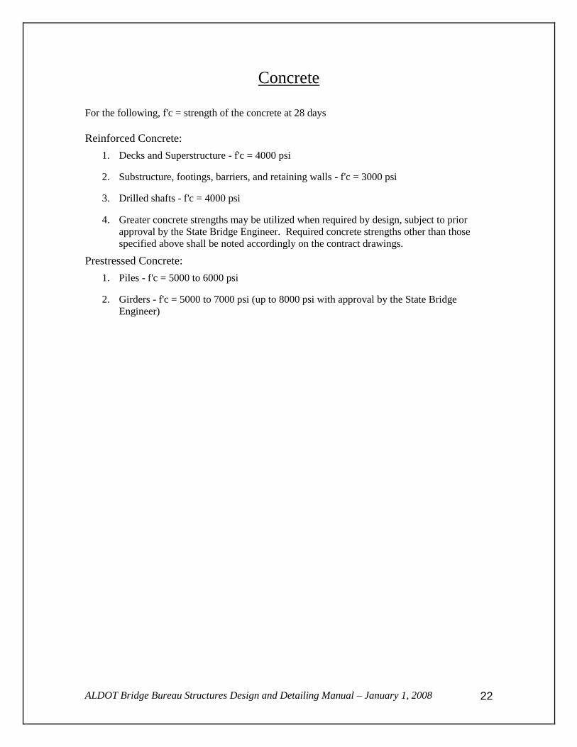
Concrete
For the following, f'c = strength of the concrete at 28 days
Reinforced Concrete:
1. Decks and Superstructure - f'c = 4000 psi
2. Substructure, footings, barriers, and retaining walls - f'c = 3000 psi
3. Drilled shafts - f'c = 4000 psi
4. Greater concrete strengths may be utilized when required by design, subject to prior
approval by the State Bridge Engineer. Required concrete strengths other than those
specified above shall be noted accordingly on the contract drawings.
Prestressed Concrete:
1. Piles - f'c = 5000 to 6000 psi
2. Girders - f'c = 5000 to 7000 psi (up to 8000 psi with approval by the State Bridge
Engineer)

ALDOT Bridge Bureau Structures Design and Detailing Manual – January 1, 2008
23
Reinforcing Steel
1. Deck slab: ASTM A615, Grade 60 billet steel (fs = 24 ksi)
2. All Other Locations: ASTM A615, Grade 40 (fs = 20 ksi) or Grade 60 (fs = 24 ksi)
billet steel.
(NOTE: If Grade 60 steel is required by design, it should be noted accordingly on
the bridge drawings.)
3. Clearances (concrete cover):
a. Bridge deck slab – 2 inches top and sides of slab, and 1 inch on bottom
of slab.
b. Columns - 2 inches for separation structures and 3 inches for structures
in waterways.
c. Caps – 2 inches top, bottom, and sides.
d. Rock or pile footing – 3 inches bottom and sides.
e. Spread footing – 4 inches bottom and sides.
f. Abutments – 3 inches bottom, 2 inches sides and top of cap and top of
backwall, 1 ½ inches faces of backwall.
g. Drilled shafts – 6 inches sides, 12 inches bottom
4. Spacing limitations:
a. The minimum spacing of reinforcement shall be in accordance with
AASHTO Section 8.21.1.
b. Where positive or negative reinforcement is placed in two or more
layers, bars in the upper layers shall be placed directly above the bottom
layer with clear distance between layers not less than 4 inches.
c. The maximum spacing of positive or negative reinforcement shall not
exceed 9 inches.

ALDOT Bridge Bureau Structures Design and Detailing Manual – January 1, 2008
24
Prestressing Steel 1. Prestressing steel shall meet specification AASHTO M203.
2. Pretensioned 0.6-inch diameter strands may be used with the approval of the State
Bridge Engineer.
Structural Steel Main Members (girders, rolled beams, lateral bracing, diaphragms, stiffeners, vertical
connection plates, etc.) shall be AASHTO M 270 Grade 36, Grade 50, or Grade 50W. The
use of Grade 50W unpainted "weathering steel" shall require prior approval of the State
Bridge Engineer.
Miscellaneous Members (armor plates, ladders, catwalks, anchor bolts, clip angles, etc.) shall
be AASHTO M 270 Grade 36 or Grade 50.
Bridge Railings
Use bridge railing as detailed on Standard Drawing I-131 and approach railing per roadway
standard drawings. Use of other crash tested rail systems shall require prior approval
from the State Bridge Engineer.
ALDOT Bridge Bureau Structures Design and Detailing Manual – January 1, 2008
25
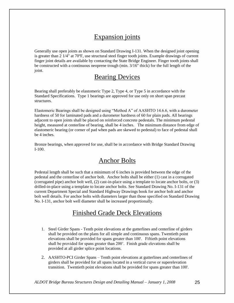
Expansion joints
Generally use open joints as shown on Standard Drawing I-131. When the designed joint opening
is greater than 2 1/4" at 70ºF, use structural steel finger tooth joints. Example drawings of current
finger joint details are available by contacting the State Bridge Engineer. Finger tooth joints shall
be constructed with a continuous neoprene trough (min. 3/16" thick) for the full length of the
joint.
Bearing Devices
Bearing shall preferably be elastomeric Type 2, Type 4, or Type 5 in accordance with the
Standard Specifications. Type 1 bearings are approved for use only on short span precast
structures.
Elastomeric Bearings shall be designed using “Method A” of AASHTO 14.6.6, with a durometer
hardness of 50 for laminated pads and a durometer hardness of 60 for plain pads. All bearings
adjacent to open joints shall be placed on reinforced concrete pedestals. The minimum pedestal
height, measured at centerline of bearing, shall be 4 inches. The minimum distance from edge of
elastomeric bearing (or corner of pad when pads are skewed to pedestal) to face of pedestal shall
be 4 inches.
Bronze bearings, when approved for use, shall be in accordance with Bridge Standard Drawing
I-100.
Anchor Bolts Pedestal length shall be such that a minimum of 6 inches is provided between the edge of the
pedestal and the centerline of anchor bolt. Anchor bolts shall be either (1) cast in a corrugated
(corrugated pipe) anchor bolt well, (2) cast-in-place using a template to locate anchor bolts, or (3)
drilled-in-place using a template to locate anchor bolts. See Standard Drawing No. I-131 of the
current Department Special and Standard Highway Drawings book for anchor bolt and anchor
bolt well details. For anchor bolts with diameters larger than those specified on Standard Drawing
No. I-131, anchor bolt well diameter shall be increased proportionally.
Finished Grade Deck Elevations
1. Steel Girder Spans - Tenth point elevations at the gutterlines and centerline of girders
shall be provided on the plans for all simple and continuous spans. Twentieth point
elevations shall be provided for spans greater than 100'. Fiftieth point elevations
shall be provided for spans greater than 200’. Finish grade elevations shall be
provided at all girder splice point locations.
2. AASHTO-PCI Girder Spans – Tenth point elevations at gutterlines and centerlines of
girders shall be provided for all spans located in a vertical curve or superelevation
transition. Twentieth point elevations shall be provided for spans greater than 100'.

ALDOT Bridge Bureau Structures Design and Detailing Manual – January 1, 2008
26
Camber Ordinates for Steel Girders Two sets of camber ordinates shall be calculated and shown; (1) camber due to dead load of steel
only, and(2) total dead load camber (steel + concrete). Ordinates shall be calculated and shown at
the same points required in Item No. 1 above for Finished Grade Elevations.
Build-up over Top of Prestressed Concrete Girders
Calculate and show the 60-day prestress camber at the mid-span of the girder before and after
placement of deck slab. The girder depth, build-up thickness, deck thickness, and total deck plus
build-up thickness at the end of the girder shall be shown on the prestress camber
diagram. The following are recommended build-ups to be provided at the end of prestressed
girders:
AASHTO
Girder Type
Minimum Build-up (Slab + Haunch)
at End of Girder
I 7 1/2"
II 9"
III 9"
BT-54 & BT-54M 10 1/2"
BT-63 10 1/2"
BT-72 10 1/2"
Note: Where spans are in a vertical curve, superelevation transition, or other complex roadway
geometry, the build-up should be investigated for each girder line and adjusted as
necessary.

ALDOT Bridge Bureau Structures Design and Detailing Manual – January 1, 2008
27
Prestressed Concrete Girder Diaphragms
Concrete Diaphragms shall be used at span ends to strengthen the free edge of the slab
and to transmit lateral forces to the substructure. Concrete intermediate diaphragms shall
be placed between the girders at the points of maximum moments for spans over 40 feet
in length. For girders over 100 ft in length, concrete diaphragms shall be placed at the
quarter points in addition to the mid-point. Diaphragms directly over substructure units
shall be designed to allow adequate space for placement of anchor bolts whenever anchor
bolts are required by design.
Seismic Provisions All bridge designs shall be checked for Seismic Category requirements.
Deck Drainage Water from bridge decks shall be allowed to fall freely to the ground through deck scuppers and
open joints, except over streets and railroads. Closed drainage systems shall only be used in
special conditions where water draining to the ground is not permitted (Example: Urbanized
Area).

ALDOT Bridge Bureau Structures Design and Detailing Manual – January 1, 2008
28
Superstructure Design General Design Assumptions:
1. Allow 15 psf dead load for use of metal stay-in-place forms.
2. Thermal loads - Erection temperature shall be assumed to be 70ºF.
3. Wind loads - Special consideration shall be given to high level coastal structures for
hurricane wind loads.
4. Deflection - Live load deflection shall not exceed L/1000
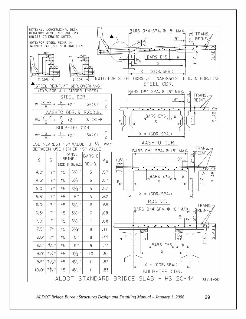
Reinforced Concrete Decks:
The State Bridge Engineer has furnished a table that addresses the design of the bridge deck slab
(See page 29). Required slab thickness and reinforcement based on girder type and girder spacing
are provided in the table that follows on the next page. Designs shall be prepared based on this
information and any exceptions will require prior approval of the Bridge Engineer.
ALDOT Bridge Bureau Structures Design and Detailing Manual – January 1, 2008
29
ALDOT Bridge Bureau Structures Design and Detailing Manual – January 1, 2008
30
Prestressed Concrete Girder Design Policy 1. Typically use AASHTO-PCI type girders (Types I, Type II, Type III, BT-54, BT-63
and BT-72). A modified BT-54 section (8” web) may be used under special
circumstances (i.e., clearance problems, freeboard, etc.) when approved by the State
Bridge Engineer.
2. All AASHTO-PCI type girders shall be designed as simple spans for all dead and live
loads, and in no case shall be made continuous by attaching the ends of girders to the
diaphragm.
3. The transformed area of bonded reinforcement shall not be included in calculations
of the section properties for prestressed girders.
4. Typically f'c = 5000 to 7000 psi (f'c up to 8000 psi is allowed when significant cost
can be saved. Any design that will require f'c greater than 7000 psi shall require prior
approval of the State Bridge Engineer.)
5. Pretensioning strand shall be 0.5” diameter (or 0.6” diameter when approved for use
by the State Bridge Engineer), low relaxation, 270 ksi Ultimate Tensile Strength. Use
strand areas as follows:
a. 0.5” diameter Low relaxation strand (A = .153 square inches)
b. 0.5” diameter Special low relaxation strand (A = .167 square inches)
c. 0.6” diameter Low relaxation strand (A = .217 square inches)
(See “Prestressing Steel” Section of this document for other requirements)
6. Maximum tensile stresses for prestressed members after losses should preferably
be designed so that no tension occurs under service load conditions. Exceptions
to this policy shall require prior approval of the State Bridge Engineer.
In no case shall service load tension exceed three times the square root of f'c.
7. Shear steel shall not be spaced greater than 18 inches on center. Shear steel in the
girder ends shall be spaced not to exceed 4 inches on center for a distance equal to
the girder depth.
9. Calculation of camber due to prestress prior to pouring the bridge deck shall be based
on a 60-day interval between release of the strand and erection of the girder.
10. Partial debonding of strands by means of plastic sheathes placed around the strands is
an acceptable method of reducing stresses at girder ends. The number of partially
debonded strands shall not exceed 25% of the total number of strands. The number of
debonded strands in any horizontal row shall not exceed 40% of the strands in that
row. The lengths of debonding shall be such that maximum use of staggering the
termination points is utilized. Debonded strands shall be symmetrically distributed
about the centerline of the member. Debonded lengths of pairs of strands,
symmetrically positioned about the centerline of the member, shall be equal.
Debonding of exterior strands is not allowed.

ALDOT Bridge Bureau Structures Design and Detailing Manual – January 1, 2008
31
Steel Girder Design Policy
1. Girders shall be designed as a composite section in the region where the concrete slab
is in compression under dead load. For continuous girders, the regions where the slab
is in tension shall be designed as non-composite.
2. All shop connections shall be welded in accordance with the Standard Specifications.
3. Field connections shall be bolted with 7/8" diameter high strength AASHTO M 164
Bolts in 15/16" diameter holes. All nuts, washers and bolts shall be mechanically
galvanized.
4. When significant fill settlements are anticipated, simple spans shall be used.
5. Flange plates shall be a minimum of 1" thick and 12" wide.
6. Plate girder design utilizing a hybrid section (differing steel grade in flanges vs.
webs) is not allowed.
7. Only Grade 36, Grade 50, painted steel shall be used in design. Design using higher
strength steel and/or weathering steel shall require prior approval of the Bridge
Engineer.
8. Designs requiring field welding on steel girders, girder diaphragms, cross frames or
lateral bracing, are not permitted. In addition, all other structural steel requiring
connections such as catwalks and bearing inspection platforms should be designed
using shop welded or field bolted connections.
9. Shop flange splices required by change in plate thickness or width shall not be used
unless a minimum of 1500 pounds of structural steel can be saved by addition of a shop splice.
10. The minimum radius for heat curving of beams and girders shall be checked in
accordance with AASHTO Specification 10.15.2.1 and noted on the plans if
prohibited by the specifications.
11. Fabrication, transportation, and erection of structural steel members shall be
considered during design. Piece lengths (girders flange + web) joined by bolted field
splices shall not exceed 130 feet and maximum gross weight for piece lengths shall
not exceed 50 tons.
12. For additional guidance regarding design considerations for fabrication,
transportation, and erection of structural steel members, the designer is encouraged to
refer to AASHTO/NSBA Steel Bridge Collaboration Manual G12.1-2003,
“Guidelines for Design Constructibility”.

ALDOT Bridge Bureau Structures Design and Detailing Manual – January 1, 2008
32
Minimum Size of Fillet Welds
The minimum fillet weld size shall be as shown in the following table. Using this table,
the minimum weld size shall be determined by the thicker of the two parts joined unless a
larger size is required by calculated stress. The weld size need not exceed the thickness
of the thinner part joined.
Material Thickness of
Thicker Part Joined
Minimum Size of
Fillet Weld
To ½” inclusive 3 / 16”
Over ½” to ¾” 1 / 4 ”
Over ¾” to 1 ½” 5 / 16 ”
Over 1 ½” to 2 ¼” 3 / 8 ”
Over 2 ¼” to 6” 1 / 2 ”
Steel Fabrication
Camber Simple Spans:
1. Rolled Beams:
a. Beams shall be cambered in the shop by the heat-upset method for the
total dead load deflection, vertical curvature, and concrete shrinkage. Use
minimum amount of heat to obtain required curvature. Maximum
allowable temperature is 1100ºF.
b. Total dead load camber for composite beams shall be increased 10% to
compensate for additional deflection due to concrete shrinkage. Camber
in screed shall also be adjusted to provide for this additional deflection.
2. Plate Girders:
a. Girders shall be cambered in the shop by cutting the camber into the web
plates for total dead load deflections, vertical curvature, and concrete
shrinkage.
b. Total dead load camber for composite girders shall be increased 10% to
compensate for additional deflection due to concrete shrinkage. Camber
in screed shall also be adjusted to provide for this additional deflection.

ALDOT Bridge Bureau Structures Design and Detailing Manual – January 1, 2008
33
Camber Continuous Spans:
1. Rolled Beams shall be cambered in the shop by the heat-upset method for the total dead
load deflection and vertical curvature. Use minimum amount of heat to obtain required
curvature. Maximum allowable temperature is 1100ºF.
2. Plate Girders shall be cambered in the shop by cutting the camber into the web plates for
total dead load deflections, and vertical curvature.
Shear Connector Studs:
Shear connector studs shall be a minimum of 5 inches in length and shall conform to AASHTO
M 169.
Shop Connections:
1. All shop-welded joints shall be made using pre-qualified joints for bridge applications of
the ANSI/AASHTO/AWS D1.5-2002 modified in accordance with the provisions of the
Standard Specifications and Special Provisions.
2. Intersecting welds will not be permitted.
a. Corners of transverse stiffeners shall be clipped and welded as follows:
1) Stiffener to web welds shall be terminated one (1) inch plus or minus
1/4 inch from clip.
2) Stiffener to flange welds shall be terminated one-half (1/2) inch plus
or minus 1/4 inch from the edges of the stiffener plate.
b. Longitudinal stiffeners shall be cut back a minimum of two (2) inches to
avoid intersecting welds.
3. When design lengths of web and flange plates exceed available lengths from rolling
mills, material may be shop spliced utilizing pre-qualified full penetration butt welds at
approximately the one-quarter and/or three-quarter point of the required material lengths.
Shop welded flange splices shall be a minimum of two (2) feet from shop web splices.
Field Connections:
1. Main Members: Field splices of beams and girders shall be made using 7/8 inch diameter
AASHTO M 164 High Strength Bolts in 15/16 inch diameter holes.
2. Cross Frames and Diaphragms: Cross frames and diaphragms are to be bolted using 7/8
inch diameter AASHTO M 164 High Strength Bolts in 15/16 inch diameter holes.
Lateral Bracing:
1. The connection of lateral bracing gusset plates to girders and cross frames shall be made
using 7/8-inch diameter AASHTO M 164 High Strength Bolts in 15/16-inch diameter
holes.
2. The connection of lateral bracing members to gusset plates shall be made using 7/8-inch
diameter AASHTO M 164 High Strength Bolts in 15/16-inch diameter holes. Holes in
gusset plate for lateral bracing member connection may be oversized (1 1/16 inch
diameter). Hole spacing and edge distance must also be increased if oversized holes are
used.

ALDOT Bridge Bureau Structures Design and Detailing Manual – January 1, 2008
34
Minimum Edge Distance:
The minimum edge distance of 15/16-inch diameter holes for 7/8-inch diameter High
Strength Bolts shall be 1 3/4 inches.
ALDOT Bridge Bureau Structures Design and Detailing Manual – January 1, 2008
35
Substructure For short span structures (50 feet and less), pile bents with reinforced concrete caps shall be used
if (1) calculated scour does not prohibit use of this type structure and (2) subsurface material is
such that piles can be driven to obtain a minimum of 10 foot of penetration into natural ground.
Reinforced concrete framed bents (or hammerhead piers when approved by the Bridge Engineer),
shall generally be used when span lengths being supported exceed 50 feet. Supports for these type
foundations shall either be soil footings, rock footings, steel H-pile footings, prestressed concrete
pile footings, or reinforced concrete drilled shafts.
ALDOT discourages the use of hammerhead piers on a single drilled shaft. Any design utilizing
hammerhead piers on a single drilled shaft shall have prior approval of the Bridge Engineer.
For designs utilizing drilled shafts, the substructure cap shall be a minimum of 6 inches wider
than the column (or drilled shaft if shaft extends to bottom of cap). The purpose for this
requirement is to account for possible mislocation of the shaft during construction. Per Article
506.11(a) of the Standard Specifications, a drilled shaft can be constructed a maximum of 3
inches out of plan location and still be considered acceptable. Eccentric loading that will result
from out-of-location shafts should be considered during the design of the substructure.
Structural (reinforced) seal concrete footings shall typically be specified if the bridge is to be
subjected to barge/ship impact loads. Piers over navigable waterways shall be designed to
withstand barge/ship impact loading. See “Structural Design Criteria” section of this document
for barge impact design requirements.
Design/detail of the required supports shall be in accordance with the recommendations of the
foundation report.
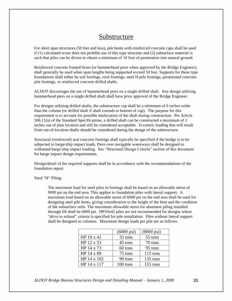
Steel "H" Piling:
The maximum load for steel piles in footings shall be based on an allowable stress of
9000 psi on the end area. This applies to foundation piles with lateral support. A
maximum load based on an allowable stress of 6000 psi on the end area shall be used for
designing steel pile bents, giving consideration to the height of the bent and the condition
of the subsurface soils. The maximum allowable stress for abutment piling installed
through fill shall be 6000 psi. HP10x42 piles are not recommended for designs where
“drive to refusal” criteria is specified for pile installation. Piles without lateral support
shall be designed as columns. Maximum design loads per pile are as follows:
(6000 psi) (9000 psi)
HP 10 x 42 35 tons 55 tons
HP 12 x 53 45 tons 70 tons
HP 14 x 73 60 tons 95 tons
HP 14 x 89 75 tons 115 tons
HP 14 x 102 90 tons 135 tons
HP 14 x 117 100 tons 155 tons

ALDOT Bridge Bureau Structures Design and Detailing Manual – January 1, 2008
36
Precast Prestressed Concrete Piling:
Prestressed concrete piling shall be designed in accordance with Standard Drawing No.
PSCP-1 from the current Special and Standard Highway Drawings book and the loadings
in the following table.
Maximum design loads per pile are as follows:
Maximum Design Loads for PPC piles
14 inch Square 60 tons
16 inch Square 80 tons
18 inch Square 100 tons
20 inch Square 120 tons
24 inch Square 160 tons
30 inch Square 190 tons
36 inch Square 250 tons
The loadings provided in the table above are for foundation (footing) piles only. The loadings
will be less for pile bents depending on the height of the bent and the condition of the
subsurface. Piles without lateral support shall be designed as columns.
ALDOT Bridge Bureau Structures Design and Detailing Manual – January 1, 2008
37
Retaining Walls The Department’s Special and Standard Drawings book has retaining wall details to address fill
heights up to 34 feet. These details are provided on Standard Drawing No. RW 10-4 (4 sheets).
For fill heights greater than 34 feet requiring special design, the engineer shall have the
responsibility of providing a design that satisfies the latest AASHTO design requirements.
Unless geometrics or foundation conditions dictate otherwise, information shown on Std. Dwg.
RW 10-4 shall be used as guidance in preparing the necessary plan details.
Temporary Retaining Walls:
The contractor shall be responsible for providing the design and details for all temporary
retaining walls.
Permanent Walls:
1. Conventional:
The Bridge Bureau shall be responsible for providing the design and details for all
retaining walls unless a consultant has been contracted to provide such items as part of a
complete set of plans.
2. Proprietary:
The contractor shall be responsible for providing the design and details for all proprietary
retaining walls.

ALDOT Bridge Bureau Structures Design and Detailing Manual – January 1, 2008
38
Concrete Box Culverts
General:
The Hydraulic Section of the Bridge Bureau is responsible for sizing all bridge culverts.
The Hydraulic Section is responsible for recommending whether the culvert shall be cast-
in-place or precast and this shall be shown on the roadway plans. The Bridge Bureau (or
selected consultant) is responsible for the design and details of cast-in-place culverts and
for reviewing the contractor's structural details for precast culverts. The State Bridge
Engineer will furnish culvert details (standards) to the consultant as needed.
Cast-in-Place Culverts:
The Bridge Bureau (or selected consultant) is responsible for the design and details of all
cast-in-place concrete box culverts, open bottom culverts that are to be constructed on
sound rock foundation, and special culvert or special hydraulic structures. The Roadway
Designer is responsible for providing the basic geometric, fill height, and slope
information needed for the design and detailing of the hydraulic structure.
Precast Culverts:
The structural design and details for the precast culvert shall conform to the Standard
Specifications for Reinforced Concrete Box Culverts. The contractor is responsible for
providing a precast culvert that has been manufactured in accordance with the provisions
of AASHTO M273 and/or AASHTO M259 as applicable. For culvert openings and fill
heights not shown in AASHTO M273 and/or M259, the contractor shall submit a design
(prepared and stamped by an Alabama Registered Professional Engineer not employed by
the Department Of Transportation) to the Bridge Engineer for approval in accordance
with the Standard Specifications. The Bridge Bureau is responsible for the review of the
details and designs submitted.

ALDOT Bridge Bureau Structures Design and Detailing Manual – January 1, 2008
39
Overhead Highway Sign Structures
Overhead Sign Bridge (OHSB) and Overhead Cantilever (OHC):
The contractor is responsible for submitting a completed design and details including
shop drawings, in accordance with Standard Specification 715, Overhead Roadway Sign
Structures and 718, Structures For Traffic Control Devices and Highway Lighting.
Consultants under direct contract with the Department will review the structural design
and shop drawings. Overhead Cantilever sign structures shall be designed for
consideration for fatigue of the anchor bolts due to wind induced vibrations
Bridge Mounted and OHSB or OHC Mounted to Bridge Substructure:
Definitions:
Sign Structure – The structure that is attached to a bridge member providing support to
the sign brackets.
Sign Brackets – The structural members to which the sign is directly attached.
The Bridge Bureau or consultants under direct contract with the Department shall be
responsible for providing the design and details for bridge mounted signs. The Bridge
Bureau will provide a design and details for OHSB or OHC mounted to a bridge
substructure. The contractor is responsible for submitting shop drawings, in accordance
with Standard Specification Sections 715, Overhead Roadway Sign Structures and 718,
Structures For Traffic Control Devices And Highway Lighting, for review by the Bridge
Bureau or consultants under direct contract with the Department. The contractor is also
responsible for providing the sign bracket design, which shall be stamped and signed by a
Professional Engineer registered in the State of Alabama. For OHSB or OHC sign
structures mounted to the substructure, a note shall be added to the plans requiring a steel
template be used to secure the anchor bolts in the proper location and position when
concrete is placed. Anchor Bolt design shall be provided by the contractor’s overhead
sign structure designer.
Re-evaluation of Existing OHSB or OHC :
The Bridge Bureau is responsible for re-evaluating existing OHSB or OHC sign
structures where additional signage is needed or existing signs are replaced with larger
ones.
ALDOT Bridge Bureau Structures Design and Detailing Manual – January 1, 2008
40
Precast Bridges Precast bridges are used routinely on low volume, secondary type routes throughout the State.
The Department’s Special and Standard Drawings book offers standard precast bridge details
(spans, bents, and abutments) for span lengths of 24 feet, 34 feet, and 40 feet and bridge widths
(gutter to gutter) of 24 feet, 24.5 feet, and 28 feet.
Miscellaneous Structures The Bridge Bureau is responsible for providing the design and details for all miscellaneous
structures unless a consultant has been contracted to provide such items as part of a complete set
of plans.

ALDOT Bridge Bureau Structures Design and Detailing Manual – January 1, 2008
41
Plans and Detail Criteria
Content of Bridge Plans:
The following information is general in nature regarding plan requirements for bridge contract
drawings. For a more detailed description of information that needs to be addressed on each
sheet, refer to the ALDOT Bridge Bureau Bridge Plans Check List Document.
Bridge Plans are composed of a sheet or sheets covering each of the following aspects of a
structure and are usually presented in the plans in similar order as follows:
General Plan and Elevation
Substructure Layout (Footing Plan - Not required for all structures)
Deck Elevations
Deck Details
Girder and Framing Details (Steel or Concrete)
Abutment Details
Pier Details
Foundation Borings
General Notes are covered by Standard Drawing No. BGN-1 and Standard Details are covered by
Standard Drawing No. I-131. Both of these standard drawings are a part of every set of bridge
plans.

ALDOT Bridge Bureau Structures Design and Detailing Manual – January 1, 2008
42
General Plan and Elevation (GP&E)
The GP&E sheet(s) shall contain a scale drawing of the entire bridge in plan and
elevation view. Plan view may be eliminated on single symmetrical structure on tangent
with no skew or superelevation transition.
This sheet shall contain but not limited to the following information:
1. Index of Bridge Drawings and/or list of Required Bridge Drawings
2. Estimated Quantities
3. Overall length of bridge
4. Alignment or curve data
5. Grade data and finished grade elevations
6. Designation of finished grade and profile grade relationship
7. Skew angle of bridge
8. Beginning and ending stations
9. Fixed and expansion ends
10. Type of bearings (if required - Sole Plates, Bevels, Etc.)
11. Approx. footing elevations for rock or spread footings
12. Actual footing elevation for pile footings and the estimated and minimum pile tip
elevations.
13. General Notes (Bridge Width & Railing Type under the General Notes)
14. Pile design loadings
15. Control dimensions (If required span lengths, joint widths; centers of columns
and/or bents if other than centers of joints, including stations)
16. Any special notes for the project. (D.L. Camber, Seal Joint, Stay-In-Place form,
Concrete piles on coast, etc.)
17. Numbering of bents
18. Detour information (bridge required, other roads, etc.)
19. Removal of old bridge (if required)
20. North directional arrow.
21. 4" deck drain requirements.
22. Special / standard drawings No.s (Special/Standard Highway Drawings)

ALDOT Bridge Bureau Structures Design and Detailing Manual – January 1, 2008
43
For structures over waterway, the GP&E Sheet shall contain the following:
1. Show all of the hydraulic data provided by the Hydraulic Engineer. As a minimum
show the 50 year, 100 year, and the 200 year flood elevations and the pool elevations
for major rivers.
2. Opening provided and the water velocity of the design year flood, typically the 50
year flood.
3. Note, the greater of the Overtopping or Q200 year flood data shall be shown on the
roadway plan and profile sheets as appropriate.
4. Clearances, horizontal and vertical (If navigable waterway)
5. Name of waterway
7. Bridge Layout Sketch
8. Direction of flow
9. Riprap slope protection as designed by the Hydraulic Engineer (No quantity
required - Roadway Item).
10. Location of deck drains
11. Construction joint location in columns at 20' maximum pour height.
For structures over railroads, the GP&E sheet shall contain the following:
1. Name of Railroad
2. Distance to nearest Mile Post
3. Directional information (To Birmingham, etc.)
4. Angle of skew of Railroad.
5. Track curve data
6. Minimum horizontal clearance lines
7. Actual vertical clearance point (6' from centerline of track)
8. Proposed future tracks
9. Intersection stationing
10. Crash walls (Crash walls required if less than 25' clear, except, on pile bents,
place separate crash walls on each pile bent extending at least 6' on either side of the
pile.
11. Slope paving (no quantity - roadway item).
12. Location of deck drains
13. Construction joint location in columns at 20' maximum pour height.

ALDOT Bridge Bureau Structures Design and Detailing Manual – January 1, 2008
44
For grade separation structures, the GP&E sheets shall contain the following:
1. Name of roads
2. Vertical and horizontal clearances (17' min. vertical) (______ horizontal)
3. Skew angles
4. Intersection stationing
5. Curve data (Either road)
6. Traffic tunnel clearances (When required)
7. Construction clearances (If other than minimum)
8. Location of deck drains
9. Construction joint location in bent columns at 20' maximum pour height.
10. Bar details if skew is different from standard
11. Slope protection (no quantity - roadway item).

ALDOT Bridge Bureau Structures Design and Detailing Manual – January 1, 2008
45
Geometrics Dimensioning for the locating (constructing) the superstructure and substructure shall be clearly
and consistently shown on the plans. Details for the entire bridge plan assembly shall be
dimensioned from the same established reference line. This reference line shall be designated as
the Centerline Bridge, Centerline Survey, Centerline Roadway, Centerline North (South, East,
West) Bound Lane/Bridge, etc., as applicable.
Tangent alignment:
Stationing for span lengths for bridges on tangent alignment shall be established from
beginning to end of bridge along the reference line.
Curved alignment:
Stationing for span lengths for bridges on curved alignment shall be established from
beginning to end of bridge along the arc reference line.
For both tangent and curved alignments, the beginning and end bridge stations shall be
dimensioned to the back face of the abutment backwall. Stationing for intermediate bents shall be
dimensioned to the working line of the joint for simple span design and to the centerline of the
bent for continuous span design. (Note: Continuous prestressed girder design is not permitted by
ALDOT)

ALDOT Bridge Bureau Structures Design and Detailing Manual – January 1, 2008
46
Substructure Layout Any bridge to be constructed on a skew or a horizontal curve shall have a foundation layout
included in the plans.
For bridges to be constructed on tangent alignment, all abutments and bents shall be parallel.
Exceptions to this policy shall require prior approval of the Bridge Engineer.
For bridges to be constructed on curved alignment, all abutments and bents shall be constructed
along the radial line to the curve. For skewed bridges, the degree of skew shall be shown as the
angle between the radial line and the tangent to the curve at the point of intersection at each
substructure location.

ALDOT Bridge Bureau Structures Design and Detailing Manual – January 1, 2008
47
Estimated Quantities
Bridge Summary:
An "Estimated Quantities" list for bridge quantities shall be provided on either the "Bridge
General Plan and Elevation" sheet or a separate sheet. This list shall include pay item number,
quantity, unit, and pay item description. When dual structures are involved, the quantities shall
be broken down into lanes, (i.e., NB lane and SB lane as applicable) as well as total quantity for
each item. Quantities shall be computed and independently checked. No percentage quantity add-
ons shall be used. Steel reinforcement and structural steel shall be rounded to the nearest 100 lb.
Concrete shall be rounded to the nearest cubic yard.
Payment for every item of work shall be shown or noted in the plans.
Estimated Quantities (Individual Elements of Bridge)
There shall be separate "Estimated Quantities" on the individual detail sheets for the
superstructure and for the individual elements of the substructure. Quantities shall be computed
by the detailer and independently checked.
Judgement shall be used in presenting all Estimated Quantities, keeping in mind that the list is not
prepared for the convenience of the detailer, but rather for the use and convenience of those who
are bidding and building the bridge.
ALDOT Bridge Bureau Structures Design and Detailing Manual – January 1, 2008
48
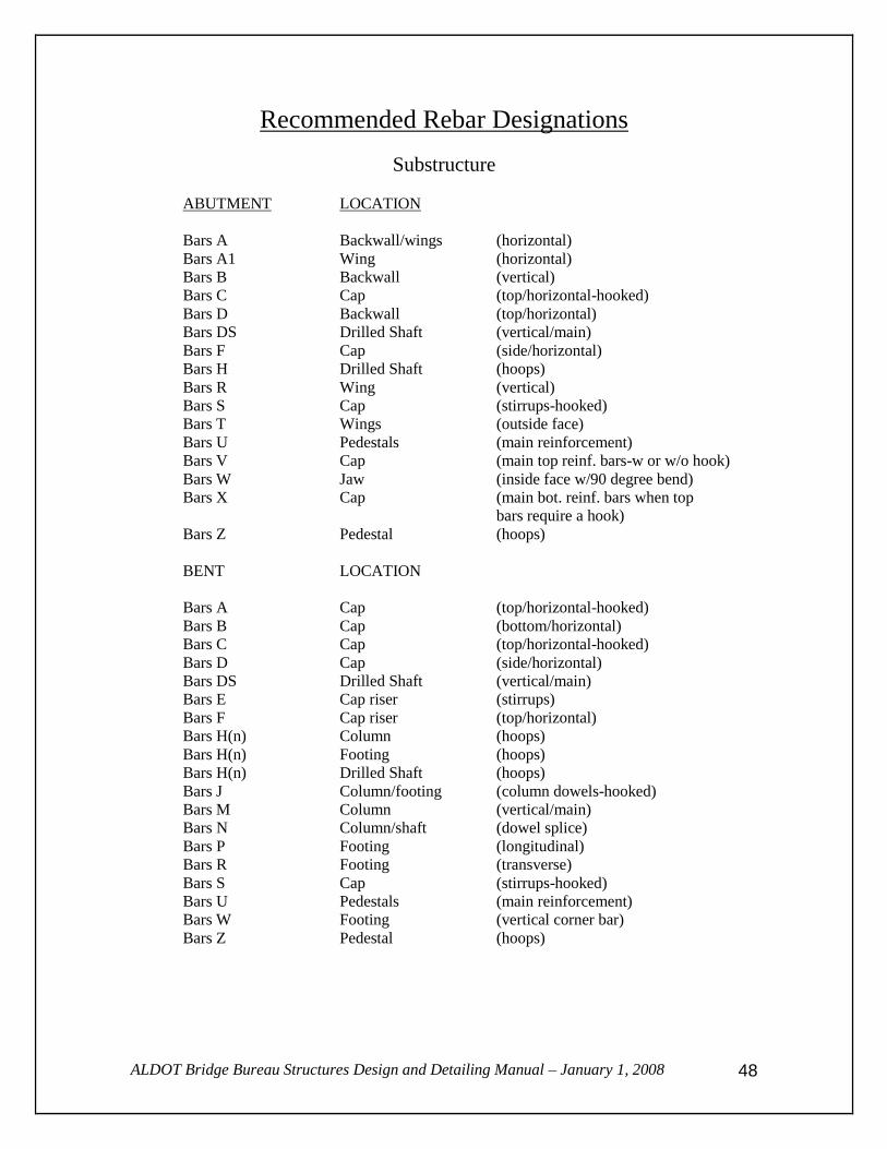
Recommended Rebar Designations
Substructure
ABUTMENT LOCATION
Bars A Backwall/wings (horizontal)
Bars A1 Wing (horizontal)
Bars B Backwall (vertical)
Bars C Cap (top/horizontal-hooked)
Bars D Backwall (top/horizontal)
Bars DS Drilled Shaft (vertical/main)
Bars F Cap (side/horizontal)
Bars H Drilled Shaft (hoops)
Bars R Wing (vertical)
Bars S Cap (stirrups-hooked)
Bars T Wings (outside face)
Bars U Pedestals (main reinforcement)
Bars V Cap (main top reinf. bars-w or w/o hook)
Bars W Jaw (inside face w/90 degree bend)
Bars X Cap (main bot. reinf. bars when top
bars require a hook)
Bars Z Pedestal (hoops)
BENT LOCATION
Bars A Cap (top/horizontal-hooked)
Bars B Cap (bottom/horizontal)
Bars C Cap (top/horizontal-hooked)
Bars D Cap (side/horizontal)
Bars DS Drilled Shaft (vertical/main)
Bars E Cap riser (stirrups)
Bars F Cap riser (top/horizontal)
Bars H(n) Column (hoops)
Bars H(n) Footing (hoops)
Bars H(n) Drilled Shaft (hoops)
Bars J Column/footing (column dowels-hooked)
Bars M Column (vertical/main)
Bars N Column/shaft (dowel splice)
Bars P Footing (longitudinal)
Bars R Footing (transverse)
Bars S Cap (stirrups-hooked)
Bars U Pedestals (main reinforcement)
Bars W Footing (vertical corner bar)
Bars Z Pedestal (hoops)

ALDOT Bridge Bureau Structures Design and Detailing Manual – January 1, 2008
49
Superstructure
SPAN LOCATION
Bars A Deck (top/transverse)
Bars C Deck (bottom/transverse)
Bar AA1 Deck (1st top mat cutoff bar for span skewed
20 degrees or greater)
Bar AA(n) Deck (last top mat cutoff bar)
Bar CC1 Deck (1st bot. mat cutoff bar for span skewed
20 degrees or greater)
Bar CC(n) Deck (last bottom mat cutoff bar)
Note: When no splicing is required for transverse deck reinforcement, both top and
bottom mat of reinforcement shall be designated as Bars C. The first pair of
cutoff bars will be designated as Bars C1 with last pair being C(n) based on last
pair being 18” out to out in length.
Bars D Deck (longitudinal/top & bottom)
Bars E Deck (longitudinal/bottom bet. girders)
Bars M Deck (top & bottom corner bars for
skewed span- see I-131 for detail)
Bars P Deck/webwall (haunch/end beam bar near
bridge joint armor plate)
Bars R Webwall (main bars)
Bars S Webwall (stirrups)
Bars S(n) Webwall (stirrups)
Bars T Webwall (threaded bar)
Bars W(n) Webwall (temperature bar in face of webwall)
For the above, (n) represents a unique bar number. For example, if a column and drilled shaft are
detailed on the same drawing, the column hoops might be assigned a designation of H1. The
drilled shaft hoops would therefore need to be assigned a separate designation of H(n), for this
example, H2.

ALDOT Bridge Bureau Structures Design and Detailing Manual – January 1, 2008
50
Reinforcement – Bar Lengths
The following lengths are recommended as maximum lengths for reinforcing bars without
providing a splice:
Bar Size Maximum Length
3 30 ft.
4 40 ft.
5 40 ft.
6 40 ft.
7 40 ft.
8 50 ft.
9 50 ft.
10 60 ft.
11 60 ft.
When splicing of transverse deck reinforcement is required, the splice should be located in a
compression zone (midpoint between girders for top bars and directly over the girder for bottom
bars).
Consideration should be given to splicing column steel whenever column height exceeds 35 feet.
Specifications allow for a 30-foot pour height for columns if steel forms are used. Just as with
drilled shaft construction, column pours become difficult whenever reinforcing steel extends
more than 5 or 6 feet above the top of the formwork.
Vertical drilled shaft reinforcing bars shall not exceed 60 feet in length.
Reinforcement - Other In accordance with Section 835 of the Standard Specifications, the fabricator can furnish either
Grade 40 or Grade 60 reinforcement unless otherwise stipulated in the Specifications or so noted
on the Bridge Drawings. For example, Article 510.02 specifies that all steel reinforcement used
in CIP bridge decks shall be AASHTO M31 Grade 60 unless otherwise noted. Similarly, Article
506.02(e) specifies that all steel reinforcement for drilled shafts shall be Grade 60. The designer
should be aware of these specifications and insure that reinforcing design requirements are clearly
noted on the bridge drawings if design requirements would dictate using higher strength steel than
addressed by Standard Specifications.
For example: If the design is based on the use of Grade 60 reinforcement in the
substructure, a plan note will need to be provided to override Section 835 of the
specifications.
Only Grade 40 or Grade 60 steel shall be utilized on ALDOT bridge designs.

ALDOT Bridge Bureau Structures Design and Detailing Manual – January 1, 2008
51
Reinforcement Presentation Plan sheets presenting the drawings for a part of the bridge, such as a pier, shall show a bill of
reinforcement of all bars pertinent to that component on the sheet including a detail for each bent
bar.
In no case, shall the same designation be used for reinforcement bars of different size, length and
shape when employed in elements of the substructure, and the same shall be applicable to bars
used in the superstructure design.
When detailing lengths of reinforcement bars, consideration must be given to transportation and
handling and, where extremely long lengths are contemplated, to availability and special orders.
All sizes of bars are readily available in lengths up to 60 feet. However, for shipping and handling
convenience, the maximum rebar lengths specified on the previous page of this document should
be considered the practical limit for all conventional structures.
If it becomes necessary to provide varying length reinforcement bars to accommodate a flared
condition on any part of a structure, do not detail the bars in a table of small increment changes in
length; detail the bars in groups of the same length to accommodate the flare by variance of lap.
All bars in the same group shall carry the same bar designation. This criterion is not to be
construed as applicable to the ends of the deck slab of a skewed structure. In this case, the bars
shall be fabricated to the required out-to-out length with a hook and marked.

ALDOT Bridge Bureau Structures Design and Detailing Manual – January 1, 2008
52
Special Provisions and Plan Notes
and Standard Drawings Bridge designers may be required to prepare plan notes and draft special provisions for special
design elements not covered by the Standard Specifications. Refer to the Department "Special
and Standard Highway Drawings" book for the commonly used miscellaneous standard drawings.
Other standard drawings may be prepared and used on a project-by-project basis.
Construction
Bridge Shop Drawings
Bridge shop drawings include, where applicable, precast items, structural steel, and all other
metal work, and the masonry connections thereof. Unless specifically noted in the contract,
consultants under direct contract with the Department will not be responsible for reviewing shop
drawings. The Bridge Bureau will generally review shop drawings. The Bridge Design Section
that prepared the plans will review prestressed concrete girder shop drawings. The Checking
Section will review structural steel shop drawings.
Bridge Working Drawings
Bridge working drawings include, where applicable, sheeting and shoring plans, cofferdam plans,
steel erection plans (all continuous), falsework plans, and other details determined to be necessary
by the Engineer. Unless specifically noted in the contract, consultants under direct contract with
the Department will not be responsible for reviewing working drawings. The Bridge Bureau and
the Construction Bureau will generally review working drawings. Working drawings will not be
reviewed unless received from the Construction Bureau in accordance with the Specifications.

ALDOT Bridge Bureau Structures Design and Detailing Manual – January 1, 2008
53
Revisions to Manual Since Last Printing 12/23/03
4/15/05 – Structural Steel Design Policy
Only Grade 36, Grade 50, painted steel shall be used in design. Design using higher
strength steel and/or weathering steel shall require prior approval of the Bridge
Engineer.
12/09/05 – Structural Steel Design Policy
Fabrication, transportation, and erection of structural steel members shall be
considered during design. Piece lengths (girders flange + web) joined by bolted field
splices shall not exceed 130 feet and maximum gross weight for piece lengths shall
not exceed 50 tons.
For additional guidance regarding design considerations for fabrication,
transportation, and erection of structural steel members, the designer is encouraged to
refer to AASHTO/NSBA Steel Bridge Collaboration Manual G12.1-2003,
“Guidelines for Design Constructibility”.
02/21/06 – Steel Piling for Abutments
The maximum allowable stress for abutment piling installed through fill shall be
6000 psi.
02/21/06 – Rainfall Spread on Bridges
Rainfall spread on the bridge (spread from gutterline) shall be limited to the shoulder
area during the design storm. The design storm shall be the 10 year frequency storm
for bridges on county routes. For all other routes, the design storm shall be the 10
year frequency except that the 50 year frequency storm shall be used for bridges
located where the low point of a sag vertical curve occurs on the bridge. Any
exceptions to this policy shall require the approval of the Bridge Engineer.
02/21/06 – Pile footings – Scour Considerations
In accordance with FHWA Hydraulic Engineering Circular No. 18 guidelines, the top
of footing for pile footing foundations should be located below the streambed a depth
equal to the estimated long-term degradation and contraction scour depth. All
exceptions to this requirement shall have prior approval of the Bridge Engineer.
Influence such as corrosion due to exposed piling, debris collection on piling, and
unbraced pile length (exposed pile below footing + depth to fixity) shall be
considered in the design of pile footing foundations whenever the top of footing is to
be constructed above the estimated long-term degradation and contraction scour
depth.