Embed Size (px)
DESCRIPTION
MHA and RET commissioning on Huawei NodeBs
Citation preview
SingleRAN
ALD Management Feature Parameter Description
Copyright © Huawei Technologies Co., Ltd. 2012. All rights reserved.
No part of this document may be reproduced or transmitted in any form or by any means without prior written consent of Huawei Technologies Co., Ltd.
Trademarks and Permissions
and other Huawei trademarks are trademarks of Huawei Technologies Co., Ltd.
All other trademarks and trade names mentioned in this document are the property of their respective holders.
Notice The purchased products, services and features are stipulated by the commercial contract made between Huawei and the customer. All or partial products, services and features described in this document may not be within the purchased scope or the usage scope. Unless otherwise agreed by the contract, all statements, information, and recommendations in this document are provided "AS IS" without warranties, guarantees or representations of any kind, either express or implied.
The information in this document is subject to change without notice. Every effort has been made in the preparation of this document to ensure accuracy of the contents, but all statements, information, and recommendations in this document do not constitute a warranty of any kind, express or implied.
Page 1 of 38ALD Management
5/06/2013http://localhost:7890/pages/31185760/05/31185760/05/resources/ref-ne/pdf/ald_manag...
Page 2 of 38ALD Management
5/06/2013http://localhost:7890/pages/31185760/05/31185760/05/resources/ref-ne/pdf/ald_manag...

Contents 1 About This Document
1.1 Scope
1.2 Intended Audience
1.3 Change History
2 Overview
2.1 Introduction
2.2 RET Antenna
2.3 TMA
2.4 SASU
3 ALD Management Functions
3.1 RET Antenna Functions
3.1.1 Connections Between RET Antennas and RRUs/RFUs
3.1.2 Operations on RET Antennas
3.2 TMA Functions
3.2.1 Connections of the TMA, RRU/RFU, and RET Antenna
3.2.2 Operations on the TMA
3.3 SASU Functions
3.3.1 Connections of the SASU, RRU/RFU, and RET Antenna
3.3.2 Operations on the SASU
4 Related Features
5 Impact on Networks
6 Engineering Guidelines
6.1 When to Use ALD Management
6.2 Information to Be Collected
6.3 Network plan
6.4 Deploying ALD Management
6.4.1 Deployment Requirements
6.4.2 Overall Process
6.4.3 Data Preparation
6.4.4 Initial Configuration
6.4.5 Activation Observation
6.4.6 Reconfiguration
6.5 Performance Optimization
6.6 Troubleshooting
7 Engineering Guidelines (UMTS/LTE)
7.1 When to Use ALD Management
7.2 Information to Be Collected
7.3 Network Planning
7.4 Deploying ALD Management
7.4.1 Deployment Requirements
7.4.2 Data Preparation
7.4.3 Precautions
7.4.4 Initial Configuration on the GUI
7.4.5 Initial Configuration on a Single Base Station Using MML Commands
7.4.6 Commissioning
7.4.7 Activation Observation
7.4.8 Reconfiguration
7.4.9 Deactivation
7.5 Performance Optimization
7.6 Troubleshooting
8 Engineering Guidelines (GSM)
8.1 When to Use ALD Management
8.2 Information to Be Collected
8.3 Network Planning
8.4 Deploying ALD Management
8.4.1 Deployment Requirements
8.4.2 Data Preparation
8.4.3 Precautions
8.4.4 Initial Configuration on the GUI
8.4.5 Initial Configuration on a Single Base Station Using MML Commands
8.4.6 Commissioning
8.4.7 Activation Observation
8.4.8 Reconfiguration
8.4.9 Deactivation
8.5 Performance Optimization
8.6 Troubleshooting
9 Reference Documents
Page 3 of 38ALD Management
5/06/2013http://localhost:7890/pages/31185760/05/31185760/05/resources/ref-ne/pdf/ald_manag...

1 About This Document 1.1 Scope
This document describes antenna line device (ALD) management and provides engineering guidelines. ALD management involves two GSM basic features, three UMTS basic features, and one LTE optional feature.
The GSM basic features are:
MRFD-210601 Connection with TMA (Tower Mounted Amplifier)
MRFD-210602 Remote Electrical Tilt
The UMTS basic features are:
MRFD-210601 Connection with TMA (Tower Mounted Amplifier)
MRFD-210602 Remote Electrical Tilt
WRFD-060003 Same Band Antenna Sharing Unit (900 MHz)
The LTE optional feature is:
FDD: LOFD-001024 Remote Electrical Tilt Control
TDD: TDLOFD-001024 Remote Electrical Tilt Control
This document applies to the following base stations:
BTS3900 (Ver.B), BTS3900 (Ver.C), and BTS3900 (Ver.D)
BTS3900L (Ver.B), BTS3900L (Ver.C), and BTS3900L (Ver.D)
BTS3900A (Ver.B), BTS3900A (Ver.C), BTS3900A (Ver.D)
BTS3900AL (Ver.A)
DBS3900
BTS3900C, BTS3900C (Ver.B), and BTS3900C (Ver.C)
The MOs, parameters, alarms, and counters concerned match with the software version delivered with this document. For detailed information, refer to the product documentation delivered with the current software version.
1.2 Intended Audience
This document is intended for:
People who need to understand ALD management
Personnel who work with Huawei products
1.3 Change History
This section provides information about the changes in different document versions.
There are two types of changes, which are defined as follows:
Feature change: refers to a change in ALD management of a specific product version.
Editorial change: refers to a change in wording or the addition of information that was not described in the earlier version.
Document Issues The document issues are as follows:
05 (2012-11-08)
04 (2012-09-15)
03 (2012-07-23)
02 (2012-06-20)
01 (2012-04-25)
Draft C (2012-03-10)
Draft B (2012-02-15)
Draft A (2012-01-10)
05 (2012-11-08) This is the fifth official release.
Compared with issue 04 (2012-09-15), issue 05 (2012-11-08) incorporates the changes described in the following table.
04 (2012-09-15) This is the fourth official release.
Compared with issue 03 (2012-07-23), issue 04 (2012-09-15) incorporates the changes described in the following table.
03 (2012-07-23) This is the third official release.
Compared with issue 02 (2012-06-20), issue 03 (2012-07-23) incorporates the changes described in the following table.
Change Type
Change Description Parameter Change
Feature change
None None
Editorial change
Add the description of RRU/RFUs connecting to the TMA in chapter 2 Overview.
None
Change Type
Change Description Parameter Change
Feature change
None None
Editorial change
Added common parameters RRU/RFU RX channel attenuation in Table 6-2.
None
Change Type
Change Description Parameter Change
Feature None None
�
�
�
�
�
�
�
�
�
�
�
�
�
�
�
�
�
�
�
�
�
�
�
Page 4 of 38ALD Management
5/06/2013http://localhost:7890/pages/31185760/05/31185760/05/resources/ref-ne/pdf/ald_manag...

02 (2012-06-20) This is the second official release.
Compared with 01 (2012-04-25), 02 (2012-06-20) incorporates the changes described in the following table.
01 (2012-04-25) This is the first official release.
Compared with draft C (2012-03-10), this issue does not incorporate any change.
Draft C (2012-03-10)
Compared with draft B (2012-02-15), draft C (2012-03-10) incorporates the changes described in the following table.
Draft B (2012-02-15) Compared with draft A (2012-01-10), draft B (2012-02-15) incorporates the changes described in the following table.
Draft A (2012-01-10) For GBSS14.0 and RAN14.0 and SRAN7.0, this is the first issue.
For eRAN3.0, this document is revised based on issue 01 (2011-09-15) of eRAN2.2. Compared with issue 01 (2011-09-15), draft A (2012-01-10) incorporates the changes described in the following table.
change
Editorial change
Added steps and data preparation for configuring a common tower-mounted amplifier (TMA). For details, see sections 7.4.3 "Precautions" and 8.4.3 "Precautions".
None
Change Type
Change Description Parameter Change
Feature change
None None
Editorial change
Deleted the table listing the connections between RF port pairs and antennas for RF modules with four RF ports. For details, see the hardware description for each type of RF module.
None
Added the method of removing RET, TMA, and SASU data in sections 7.4.9 "Deactivation" and 8.4.9 "Deactivation."
None
Change Type
Change Description Parameter Change
Feature change
None None
Editorial change
Modified chapter 6 "Engineering Guidelines", chapter 7 "Engineering Guidelines (UMTS/LTE)", and chapter 8 "Engineering Guidelines (GSM)."
None
Change Type
Change Description Parameter Change
Feature change
Added the description of the RRU connection to the RET antenna through an external BT. For details, see section 3.1.1 "Connections Between RET Antennas and RRUs/RFUs."
None
Editorial change
Added the description of capabilities of radio frequency (RF) modules to support RET antennas. For details, see section 2.1 "Introduction."
None
Clarified the ALD information to be collected at the site. For details, see section 8.4.2 "Data Preparation."
None
Moved the chapter "Engineering Guidelines" from chapter 8 to chapter 6, and added the description of the overall process and procedures of ALD configurations. For details, see chapter 6 "Engineering Guidelines."
None
Modified sources of parameters involved in data preparation based on the parameter reference.
None
Change Type
Change Description Parameter Change
Feature change
Added the description of connections between the ALD and the RRU/RFU with four RF ports. For details, see section 3.1.1 "Connections Between RET Antennas and RRUs/RFUs."
None
Added the description of connections between the ALD and the RFU. For details, see chapter 3 "ALD Management Functions."
None
Editorial change
Added the description of capabilities of RF ports to support different types of ALDs. For details, see section 2.1 "Introduction."
None
Added the engineering guidelines for a NodeB, eNodeB, and multi-mode base station (MBTS).
Added GSM and UMTS configuration parameters.
Added the description of application scenarios and operations of the SASU that is supported by UMTS.
Added configuration parameters related to the SASU.
Page 5 of 38ALD Management
5/06/2013http://localhost:7890/pages/31185760/05/31185760/05/resources/ref-ne/pdf/ald_manag...

2 Overview 2.1 Introduction
ALD is a general term for antenna devices, such as the remote electrical tilt (RET) antenna, tower-mounted amplifier (TMA), and same-band antenna sharing unit (SASU).
Table 2-1 lists the capabilities of GSM, UMTS, and LTE radio access technology (RAT) systems to configure and manage different types of ALDs.
Table legend: Yes: supported; No: not supported
Table 2-1 Capabilities of GSM, UMTS, and LTE RAT systems to configure and manage different types of ALDs
Table 2-2 and Table 2-3 list the capabilities of RF modules to support different types of ALDs.
Table legend: Yes: supported; No: not supported; /: N/A
If an RF port does not support RET antennas, control signals cannot be transmitted or received on this RF port.
Table 2-2 Capabilities of ports on RF modules with two RF ports to support different types of ALDs
G, U, and L are short for GSM, UMTS, and LTE, respectively.
RAT System RET TMA SASU
GSM Yes Yes No
UMTS Yes Yes Yes
LTE Yes Yes No
RF Module RAT System ANT_A Port ANT_B Port RET Port
RET TMA RET TMA RET TMA
DRFU GSM No No No No / /
GRFU GSM Yes Yes No Yes / /
RRU3004 GSM No No No No Yes No
RRU3008 GSM Yes Yes No Yes Yes No
WRFU UMTS Yes Yes No Yes / /
WRFUd UMTS Yes Yes No Yes / /
RRU3804 UMTS Yes Yes No Yes Yes No
RRU3801E UMTS Yes Yes No Yes Yes No
RRU3805 UMTS Yes Yes No Yes Yes No
RRU3806 UMTS Yes Yes No Yes Yes No
RRU3824 UMTS Yes Yes No Yes Yes No
RRU3826 UMTS Yes Yes No Yes Yes No
RRU3828 UMTS Yes Yes No Yes Yes No
RRU3829 UMTS Yes Yes No Yes Yes No
RRU3801C (20 W)
UMTS No No No No Yes No
RRU3801C (40 W)
UMTS Yes Yes No Yes Yes No
LRFU LTE Yes Yes No Yes / /
LRFUe LTE Yes Yes No Yes / /
RRU3201 LTE Yes Yes No Yes Yes No
RRU3202E LTE Yes Yes No Yes Yes No
RRU3203 LTE Yes Yes No Yes Yes No
RRU3220 LTE No No No No Yes No
RRU3221 LTE Yes Yes No Yes Yes No
RRU3222 LTE Yes Yes No Yes Yes No
RRU3229 LTE Yes Yes No Yes Yes No
RRU3808 UMTS, LTE Yes Yes No Yes Yes No
MRFU GSM, UMTS, LTE, GU, GL, UL
Yes Yes No Yes / /
MRFUd GSM, UMTS, LTE, GU, GL, UL
Yes Yes No Yes / /
MRFUe GSM, UMTS, LTE, GU, GL, UL
Yes Yes No Yes / /
RRU3908 GSM, UMTS, LTE, GU, GL, UL
Yes Yes No Yes Yes No
RRU3928 GSM, UMTS, LTE, GU, GL, UL
Yes Yes No Yes Yes No
RRU3929 GSM, UMTS, LTE, GU, GL, UL
Yes Yes No Yes Yes No
RRU3926 GSM, UMTS, LTE, GU, GL, UL
Yes Yes No Yes Yes No
RRU3961 GSM, UMTS, LTE, GU, GL, UL, GUL
Yes Yes No Yes Yes No
Page 6 of 38ALD Management
5/06/2013http://localhost:7890/pages/31185760/05/31185760/05/resources/ref-ne/pdf/ald_manag...

Table 2-3 Capabilities of ports on RF modules with four RF ports to support different types of ALDs
Table 2-4 lists the capabilities of RF modules to support RET antennas.
Table 2-4 Capabilities of RF modules to support RET antennas
2.2 RET Antenna
An RET antenna consists of a remote control unit (RCU) and one or more RET subunits.
For details about the RCU, smart bias-tee (SBT), and bias-tee (BT), and cables mentioned, see Overview of the Antenna System.
The RCU is the control unit of an RET antenna. The RCU can change signal coverage by adjusting the RET antenna downtilt.
RET subunits are antenna devices that can be independently controlled.
The two types of RET antennas are defined by the number of RET subunits they contain: single-antenna and multi-antenna.
A single-antenna RET antenna (SINGLE_RET) has only one RET subunit.
A multi-antenna RET antenna (MULTI_RET) has multiple RET subunits, each of which supports the configuration file download and downtilt setting. A multi-antenna RET antenna can be regarded as a set of single-antenna RET antennas installed in a radome.
The RET antenna has the following benefits:
RF Module
RAT System
ANT_A Port ANT_B Port ANT_C Port ANT_D Port RET Port
RET TMA RET TMA RET TMA RET TMA RET TMA
RRU 3841
LTE Yes Yes Yes Yes No Yes No Yes Yes No
RRU 3942
GSM, UMTS, LTE, GU, GL, UL
Yes Yes Yes Yes No Yes No Yes Yes No
RF Module RAT System AISG Protocol Supported
RET Antenna Voltage
RET Antenna Current
DRFU GSM 1.1/2.0 12 V 2.3 A
GRFU GSM 1.1/2.0 12 V 2.3 A
RRU3004 GSM 1.1 12 V 2.3 A
RRU3008 GSM 1.1/2.0 12 V 2.3 A
WRFU UMTS 1.1/2.0 12 V 2.3 A
WRFUd UMTS 1.1/2.0 12 V 2.3 A
RRU3804 UMTS 1.1/2.0 12 V 2.3 A
RRU3801E UMTS 1.1 12 V 2.3 A
RRU3805 UMTS 1.1/2.0 12 V 2.3 A
RRU3806 UMTS 1.1/2.0 12 V 2.3 A
RRU3824 UMTS 1.1/2.0 12 V 2.3 A
RRU3826 UMTS 1.1/2.0 12 V 2.3 A
RRU3828 UMTS 1.1/2.0 12 V 2.3 A
RRU3829 UMTS 1.1/2.0 12 V 2.3 A
RRU3801C (20 W)
UMTS 1.1/2.0 12 V 2.3 A
RRU3801C (40 W)
UMTS 1.1/2.0 12 V 2.3 A
LRFU LTE 1.1/2.0 12 V 2.3 A
LRFUe LTE 1.1/2.0 12 V 2.3 A
RRU3201 LTE 1.1/2.0 12 V 2.3 A
RRU3202E LTE 1.1/2.0 12 V 2.3 A
RRU3203 LTE 1.1/2.0 12 V 2.3 A
RRU3220 LTE 1.1/2.0 12 V 2.3 A
RRU3221 LTE 1.1/2.0 12 V 2.3 A
RRU3222 LTE 1.1/2.0 12 V 2.3 A
RRU3229 LTE 1.1/2.0 12 V 2.3 A
RRU3841 LTE 1.1/2.0 12 V 2.3 A
RRU3808 UMTS, LTE 1.1/2.0 12 V 2.3 A
MRFU GSM, UMTS, LTE, GU, GL, UL
1.1/2.0 12 V 2.3 A
MRFUd GSM, UMTS, LTE, GU, GL, UL
1.1/2.0 12 V 2.3 A
MRFUe GSM, UMTS, LTE, GU, GL, UL
1.1/2.0 12 V 2.3 A
RRU3908 GSM, UMTS, LTE, GU, GL, UL
1.1/2.0 12 V 2.3 A
RRU3928 GSM, UMTS, LTE, GU, GL, UL
1.1/2.0 12 V 2.3 A
RRU3929 GSM, UMTS, LTE, GU, GL, UL
1.1/2.0 12 V 2.3 A
RRU3926 GSM, UMTS, LTE, GU, GL, UL
1.1/2.0 12 V 2.3 A
RRU3942 GSM, UMTS, LTE, GU, GL, UL
1.1/2.0 12 V 2.3 A
RRU3961 GSM, UMTS, LTE, GU, GL, UL, GUL
1.1/2.0 12 V 2.3 A
�
�
�
�
Page 7 of 38ALD Management
5/06/2013http://localhost:7890/pages/31185760/05/31185760/05/resources/ref-ne/pdf/ald_manag...

Remote adjustment eliminates on-site operations. Antenna maintenance is not affected by weather, location, or other site restrictions.
High adjustment efficiency reduces network optimization and maintenance costs.
Adjustable downtilt prevents coverage distortion, which improves signal coverage and decreases neighboring cell interference.
Compared to antennas with mechanical downtilts, RET antennas have the disadvantages of higher cost and higher complexity.
2.3 TMA
A TMA is a low noise amplifier (LNA) installed next to the antenna. It improves the signal-to-noise ratio (SNR), sensitivity, and uplink coverage of the base station.
A TMA is one of two types: common TMA or smart TMA. The common TMA does not support the Antenna Interface Standards Group (AISG) protocol, while the smart TMA does. Communication between the smart TMA and the base station complies with the AISG protocol. With a built-in SBT, the smart TMA can convert RS485 control signals from the RCU to OOK signals, and OOK signals from the RRU/RFU to RS485 signals. In addition, the smart TMA can feed DC power from the remote radio unit (RRU)/radio frequency unit (RFU) to the RCU. The RCU and RRU/RFU are connected by a feeder. Unless otherwise stated in this document, "TMA" refers to smart TMA.
When an RRU/RFU connects to a TMA, at least one RF port supporting RET antennas must connect to this TMA to provide control signals for this TMA. For details about capabilities of RF modules to support RET antennas, see Table 2-2 and Table 2-3.
The TMA provides the following functions:
Amplifies uplink signals to compensate for attenuation from an antenna to an RRU/RFU.
Balances signal amplification between the uplink and the downlink.
A TMA has one or two subunits and supports amplification of one or two uplink RF signals.
2.4 SASU
An SASU is a Huawei customized device for antenna sharing between intra-band GSM and UMTS systems at a multi-mode site. Antenna sharing helps operators reduce the capital expenditure (CAPEX). Currently, the SASU supports only the 900 MHz and 2100 MHz frequency bands.
The SASU has two subunits to amplify uplink signals of GSM and UMTS systems.
�
�
�
�
�
Page 8 of 38ALD Management
5/06/2013http://localhost:7890/pages/31185760/05/31185760/05/resources/ref-ne/pdf/ald_manag...
3 ALD Management Functions 3.1 RET Antenna Functions
3.1.1 Connections Between RET Antennas and RRUs/RFUs
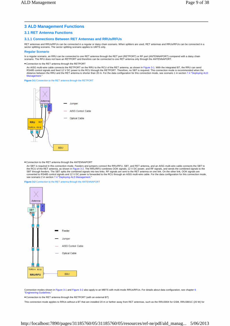
RET antennas and RRUs/RFUs can be connected in a regular or daisy chain scenario. When splitters are used, RET antennas and RRUs/RFUs can be connected in a sector splitting scenario. The sector splitting scenario applies to UMTS only.
Regular Scenario In a regular scenario, an RRU can be connected to one RET antenna through the RET port (RETPORT) or RF port (ANTENNAPORT) compared with a daisy chain scenario. The RFU does not have an RETPORT and therefore can be connected to one RET antenna only through the ANTENNAPORT.
Connection to the RET antenna through the RETPORT
An AISG multi-wire cable connects the RETPORT on the RRU to the RCU of the RET antenna, as shown in Figure 3-1. With the integrated BT, the RRU can send RS485 control signals and feed 12 V DC power to the RCU through the RETPORT. Therefore, no SBT is required. This connection mode is recommended when the distance between the RRU and the RET antenna is shorter than 20 m. For the data configuration for this connection mode, see scenario 1 in section 7.4 "Deploying ALD Management."
Figure 3-1 Connection to the RET antenna through the RETPORT
Connection to the RET antenna through the ANTENNAPORT
An SBT is required in this connection mode. Feeders and jumpers connect the RRU/RFU, SBT, and RET antenna, and an AISG multi-wire cable connects the SBT to the RCU of the RET antenna, as shown in Figure 3-2. The RRU/RFU combines OOK signals, 12 V DC power, and RF signals, and sends the combined signals to the SBT through feeders. The SBT splits the combined signals into two links. RF signals are sent to the RET antenna on one link. On the other link, OOK signals are converted to RS485 control signals and 12 V DC power is forwarded to the RCU through an AISG multi-wire cable. For the data configuration for this connection mode, see scenario 2 in section 7.4 "Deploying ALD Management."
Figure 3-2 Connection to the RET antenna through the ANTENNAPORT
Connection modes shown in Figure 3-1 and Figure 3-2 also apply to an MBTS with multi-mode RRUs/RFUs. For details about data configuration, see chapter 6 "Engineering Guidelines."
Connection to the RET antenna through the RETPORT (with an external BT)
This connection mode applies to RRUs without a BT that are installed 20 m or farther away from RET antennas, such as the RRU3004 for GSM, RRU3801C (20 W) for
�
�
�
Page 9 of 38ALD Management
5/06/2013http://localhost:7890/pages/31185760/05/31185760/05/resources/ref-ne/pdf/ald_manag...
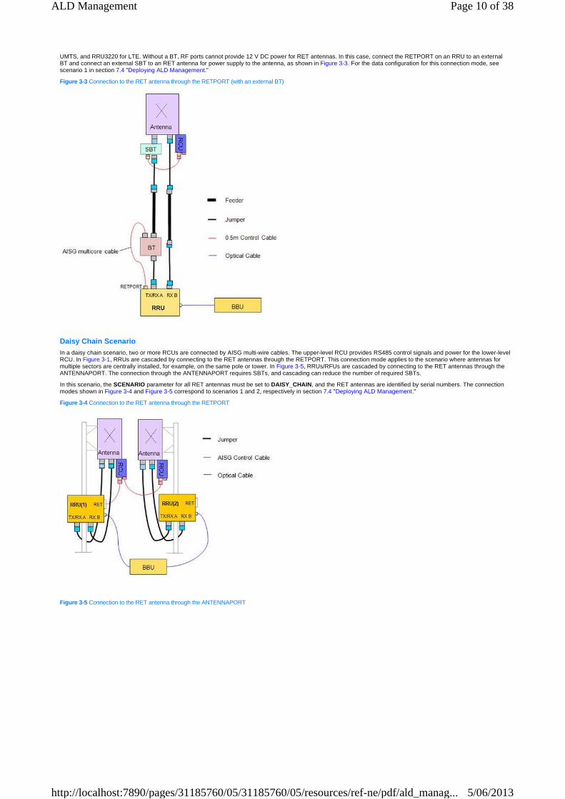
UMTS, and RRU3220 for LTE. Without a BT, RF ports cannot provide 12 V DC power for RET antennas. In this case, connect the RETPORT on an RRU to an external BT and connect an external SBT to an RET antenna for power supply to the antenna, as shown in Figure 3-3. For the data configuration for this connection mode, see scenario 1 in section 7.4 "Deploying ALD Management."
Figure 3-3 Connection to the RET antenna through the RETPORT (with an external BT)
Daisy Chain Scenario In a daisy chain scenario, two or more RCUs are connected by AISG multi-wire cables. The upper-level RCU provides RS485 control signals and power for the lower-level RCU. In Figure 3-1, RRUs are cascaded by connecting to the RET antennas through the RETPORT. This connection mode applies to the scenario where antennas for multiple sectors are centrally installed, for example, on the same pole or tower. In Figure 3-5, RRUs/RFUs are cascaded by connecting to the RET antennas through the ANTENNAPORT. The connection through the ANTENNAPORT requires SBTs, and cascading can reduce the number of required SBTs.
In this scenario, the SCENARIO parameter for all RET antennas must be set to DAISY_CHAIN , and the RET antennas are identified by serial numbers. The connection modes shown in Figure 3-4 and Figure 3-5 correspond to scenarios 1 and 2, respectively in section 7.4 "Deploying ALD Management."
Figure 3-4 Connection to the RET antenna through the RETPORT
Figure 3-5 Connection to the RET antenna through the ANTENNAPORT
Page 10 of 38ALD Management
5/06/2013http://localhost:7890/pages/31185760/05/31185760/05/resources/ref-ne/pdf/ald_manag...

Connection modes shown in Figure 3-4 and Figure 3-5 also apply to an MBTS with independent antennas. The configured RRUs/RFUs serve different systems.
The RET antenna data of an MBTS with single-mode RRUs/RFUs can be configured in only one RAT system. For details about data configuration, see chapter 6 "Engineering Guidelines." In Figure 3-4, if RRU(1) serves the GSM or LTE system (the RET data is configured in the GSM or LTE system), the SCENARIO parameters must be set to DAISY_CHAIN for RET antennas connected to RRU(1) and RRU(2). If RRU(1) serves the UMTS system (the RET data is configured in the UMTS system), the SCENARIO parameters must be set to DAISY_CHAIN and 2G_EXTENSION for the RET antennas connected to RRU(1) and RRU(2), respectively.
Some RF modules, such as the RRU3942 and RRU3841, have four RF ports. These RF modules have two or more RF ports to support RET functions in addition to the RETPORT. For details, see Table 2-3. Two RF ports on these RF modules can be paired and connected to one antenna to provide various transmit or receive functions. When the RRU3942 or RRU3841 is used, you can refer to RRU3942 Hardware Description or RRU3841 Hardware Description.
The following description assumes that the RRU3942 uses the 2T4R configuration. "T" and "R" refer to transmission and reception, respectively. RF ports ANT_A and ANT_C on the RRU3942 are paired and connected to one antenna, and RF ports ANT_B and ANT_D are paired and connected to the other antenna.
When the RRU3942 is installed less than 20 m away from RET antennas, the RRU3942 is connected to the RET antennas through the RETPORT. The RET antennas are cascaded because the RRU3942 has only one RETPORT, as shown in Figure 3-6.
Figure 3-6 Connection to the RET antenna through the RETPORT
Figure 3-7 shows how the RRU3942 and RET antennas are connected to provide the 2T4R function when the RRU3942 is installed more than 20 m away from the RET antennas and the RET antennas are centrally installed.
Figure 3-7 Connection to the RET antenna through the ANTENNAPORT
Page 11 of 38ALD Management
5/06/2013http://localhost:7890/pages/31185760/05/31185760/05/resources/ref-ne/pdf/ald_manag...

In this connection mode, RF port ANT_A is the control port for the two RET antennas connected to the RRU3942. For the data configuration for this connection mode, see scenario 2 in section 7.4 "Deploying ALD Management."
Sector Splitting Scenario The sector splitting scenario applies to UMTS only. In this scenario, the RRU/RFU is connected to splitters and then RET antennas, as shown in Figure 3-8.
Figure 3-8 Sector splitting scenario
In this scenario, the SCENARIO parameter for all RET antennas must be set to SECTOR_SPLITTING, and the RET antennas are identified by serial numbers. For the data configuration for this connection mode, see scenario 2 in section 7.4 "Deploying ALD Management."
3.1.2 Operations on RET Antennas
The base station can perform operations, including configuration file loading, antenna calibration, and downtilt setting, on each RET subunit separately.
Configuration file loading
A configuration file describes the relationship between the RCU and the RET subunit downtilt. The configuration file is provided by the RET antenna manufacturer. Some RET antennas have been loaded with default configuration files before delivery. For antennas without default configuration files, run the following command to load configuration files:
− GSM: LOD BTSRETCFGDATA
− UMTS/LTE: DLD RETCFGDATA
Ensure that correct configuration files have been loaded to the RET antennas before antenna calibration. If an incorrect configuration file is loaded, the RET antenna will experience unexpected errors, and the loaded configuration file cannot be queried. You can obtain the configuration file information only from the related operation log. You are advised to load the configuration file to the RET antennas of one or two base stations, and check whether the actual downtilts are the same as the configured downtilts. If the downtilts are the same, the configuration file is correct.
�
Page 12 of 38ALD Management
5/06/2013http://localhost:7890/pages/31185760/05/31185760/05/resources/ref-ne/pdf/ald_manag...

Before you run the LOD BTSRETCFGDATA command to load a configuration file to RET antennas of a BTS, run the DLD BTSALDFILE command to download the configuration file from the file server to the base station controller (BSC) operation and maintenance unit (OMU).
Run the following command to query dynamic information about RET additional data:
GSM: DSP BTSRETDEVICEDATA
UMTS/LTE: DSP RETDEVICEDATA
If any information is incorrect in the command output, for example, the values of Max tilt and Min tilt are NULL , no configuration file was loaded or the configuration file is lost.
Antenna calibration
After an RET antenna is installed, run the following command to calibrate the RET antenna:
− GSM: CLB BTSRET
− UMTS/LTE: CLB RET
During the calibration, the RCU adjusts the RET antenna within the downtilt range so that the RET antenna operates properly. If the RET antenna is not calibrated, the base station reports ALM-26753 RET Antenna Not Calibrated.
An RET antenna does not need to be calibrated again after it is reset or powered off.
Downtilt setting
1. After the RET antenna is calibrated, run the following command to query the supported downtilt range:
− GSM: DSP BTSRETDEVICEDATA
− UMTS/LTE: DSP RETDEVICEDATA
The downtilt range of an RET antenna varies according to the manufacturer and model.
2. Run the following command to set an RET subunit downtilt:
− GSM: MOD BTSRETSUBUNIT
− UMTS/LTE: MOD RETSUBUNIT
Setting the downtilt of an RET subunit affects the coverage of the RET antenna. Set the downtilt based on the engineering design.
The base station can perform operations on the RCU separately, including software download and RCU reset.
RCU software download
Run the following command to download RCU software:
− GSM: LOD BTSALDSW
− UMTS/LTE: DLD ALDSW
The RET antenna manufacturer provides RCU software. For details, see the documents provided by the manufacturer.
Before you run the LOD BTSALDSW command to download RCU software for a BTS, run the DLD BTSALDFILE command to download the RCU software from the file server to the BSC OMU.
RCU reset
Run the following command to reset the RCU:
− GSM: RST BTSALD
− UMTS/LTE: RST ALD
Resetting the RCU does not change the RET antenna downtilt.
3.2 TMA Functions
3.2.1 Connections of the TMA, RRU/RFU, and RET Anten na
If an RRU/RFU is to be connected to an RET antenna through a TMA, the RRU/RFU control port must be connected to the TMA control port.
Connection to the RET Antenna Through the ANTENNAPO RT (with a TMA) A TMA is connected to an RRU/RFU and RET antenna, and is powered by the RRU/RFU. Figure 3-9 shows how the TMA, RRU/RFU, and RET antenna are connected.
With the integrated SBT, the TMA splits combined signals from the RRU/RFU into two links. RF signals are sent to the RET antenna on one link. On the other link, OOK signals are converted to RS485 control signals and 12 V DC power is forwarded to the RCU through an AISG multi-wire cable. For the data configuration for this connection mode, see scenario 3 in section 7.4 "Deploying ALD Management."
Figure 3-9 Connection to the RET antenna through the ANTENNAPORT (with a TMA)
�
�
�
�
Page 13 of 38ALD Management
5/06/2013http://localhost:7890/pages/31185760/05/31185760/05/resources/ref-ne/pdf/ald_manag...
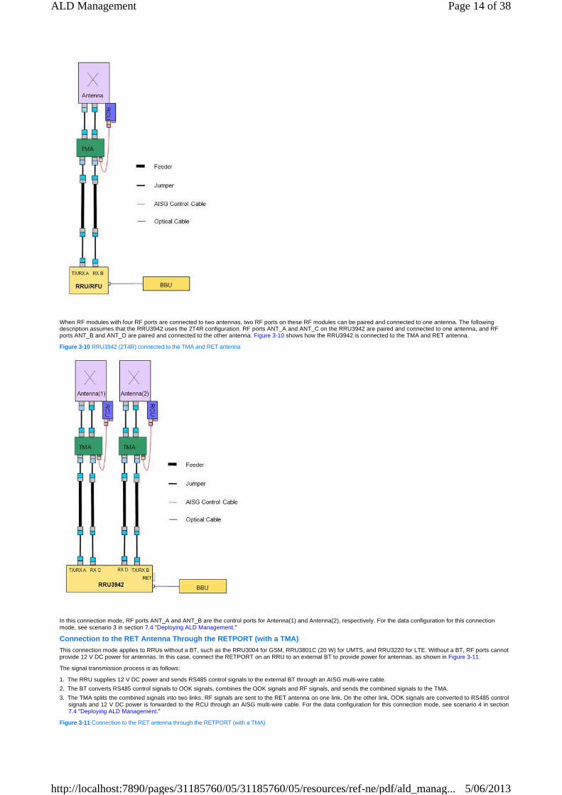
When RF modules with four RF ports are connected to two antennas, two RF ports on these RF modules can be paired and connected to one antenna. The following description assumes that the RRU3942 uses the 2T4R configuration. RF ports ANT_A and ANT_C on the RRU3942 are paired and connected to one antenna, and RF ports ANT_B and ANT_D are paired and connected to the other antenna. Figure 3-10 shows how the RRU3942 is connected to the TMA and RET antenna.
Figure 3-10 RRU3942 (2T4R) connected to the TMA and RET antenna
In this connection mode, RF ports ANT_A and ANT_B are the control ports for Antenna(1) and Antenna(2), respectively. For the data configuration for this connection mode, see scenario 3 in section 7.4 "Deploying ALD Management."
Connection to the RET Antenna Through the RETPORT ( with a TMA) This connection mode applies to RRUs without a BT, such as the RRU3004 for GSM, RRU3801C (20 W) for UMTS, and RRU3220 for LTE. Without a BT, RF ports cannot provide 12 V DC power for antennas. In this case, connect the RETPORT on an RRU to an external BT to provide power for antennas, as shown in Figure 3-11.
The signal transmission process is as follows:
1. The RRU supplies 12 V DC power and sends RS485 control signals to the external BT through an AISG multi-wire cable.
2. The BT converts RS485 control signals to OOK signals, combines the OOK signals and RF signals, and sends the combined signals to the TMA.
3. The TMA splits the combined signals into two links. RF signals are sent to the RET antenna on one link. On the other link, OOK signals are converted to RS485 control signals and 12 V DC power is forwarded to the RCU through an AISG multi-wire cable. For the data configuration for this connection mode, see scenario 4 in section 7.4 "Deploying ALD Management."
Figure 3-11 Connection to the RET antenna through the RETPORT (with a TMA)
Page 14 of 38ALD Management
5/06/2013http://localhost:7890/pages/31185760/05/31185760/05/resources/ref-ne/pdf/ald_manag...

3.2.2 Operations on the TMA
The gain of the TMA with fixed gain is not configurable.
TMA gain and working mode are configurable.
Setting TMA working mode
By default, the TMA is set to NORMAL working mode to ensure normal operation. If you run the following command with the MODE parameter set to BYPASS , the TMA serves as a straight-through feeder and does not amplify signals:
− GSM: MOD BTSTMASUBUNIT
− UMTS/LTE: MOD TMASUBUNIT
Setting TMA gain
1. Run the following command to query the value range of TMA gain:
− GSM: DSP BTSTMADEVICEDATA
− UMTS/LTE: DSP TMADEVICEDATA
2. Run the following command to set TMA subunit gain:
− GSM: MOD BTSTMASUBUNIT
− UMTS/LTE: MOD TMASUBUNIT
The base station can perform operations on the TMA separately, including software download and TMA reset.
TMA software download
Run the following command to download TMA software:
− GSM: LOD BTSALDSW
− UMTS/LTE: DLD ALDSW
The TMA manufacturer provides TMA software. For details, see the documents provided by the manufacturer.
Before you run the LOD BTSALDSW command to download TMA software for a BTS, run the DLD BTSALDFILE command to download the TMA software from the file server to the BSC OMU.
TMA reset
Run the following command to reset the TMA:
− GSM: RST BTSALD
− UMTS: RST ALD
Resetting the TMA does not change the TMA gain and working mode.
3.3 SASU Functions
3.3.1 Connections of the SASU, RRU/RFU, and RET Antenn a
Figure 3-12 shows how the SASU, RRUs/RFUs, and RET antenna are connected when RRUs/RFUs for GSM (referred to as 2G) and UMTS (referred to as 3G) share one RET antenna and the SASU is installed less than 20 m away from the RET antenna. With the integrated SBT, the SASU splits combined 3G signals from the RRUs/RFUs into two links. RF signals and 2G signals are combined and sent to the RET antenna on one link. On the other link, OOK signals are converted to RS485 control signals and 12 V DC power is forwarded to the RCU through an AISG multi-wire cable.
Figure 3-12 SASU directly connected to the RET antenna
�
�
�
�
Page 15 of 38ALD Management
5/06/2013http://localhost:7890/pages/31185760/05/31185760/05/resources/ref-ne/pdf/ald_manag...

SASU data can be configured only in the UMTS system. Because the SASU is an active device, you need to turn on the power switch for the 3G RRU control port in the UMTS system, and specify current alarm thresholds. For connection mode in Figure 3-12, set the DCSWITCH parameter for the SASU to OFF. Otherwise, the RET antenna will short-circuit. For the data configuration for this connection mode, see scenario 5 in section 7.4 "Deploying ALD Management."
Figure 3-13 shows how the SASU, RRUs/RFUs, TMA, and RET antenna are connected when the SASU is installed greater than 20 m away from the RET antenna. The SASU combines 2G and 3G signals and sends the combined signals to the TMA. The TMA splits the combined signals into two links. RF signals are sent to the RET antenna on one link. On the other link, OOK signals are converted to RS485 control signals and 12 V DC power is forwarded to the RCU through an AISG multi-wire cable.
Figure 3-13 SASU connected to the TMA and RET antenna
SASU data can be configured only in the UMTS system. In this connection mode, the DCSWITCH parameter for the SASU cannot be set to OFF because the TMA is an active device. If the DCSWITCH parameter is set to UMTS, specify the DCLOAD parameter for SASU subunits so that the TMA connected to the SASU can be acknowledged by the base transceiver station (BTS). For the data configuration for this connection mode, see scenario 6 in section 7.4 "Deploying ALD Management."
3.3.2 Operations on the SASU
The SASU DC power switch, gain, and working mode are configurable only in the UMTS system.
Setting the DC power switch
When the SASU is connected to the RET antenna through a TMA, run the MOD SASU command with the DCSWITCH parameter set to any value except OFF. When the SASU is directly connected to the RET antenna, set the DCSWITCH parameter for the SASU to OFF. Otherwise, the RET antenna will short-circuit.
�
Page 16 of 38ALD Management
5/06/2013http://localhost:7890/pages/31185760/05/31185760/05/resources/ref-ne/pdf/ald_manag...

Setting SASU working mode
By default, the SASU is set to NORMAL working mode to ensure normal operation. If you run the MOD SASUSUBUNIT command with the MODE parameter set to BYPASS , the SASU serves as a straight-through feeder and does not amplify signals.
Setting SASU gain
1. Run the DSP SASUDEVICEDATA command to query the value range of SASU gain.
2. Run the MOD SASUSUBUNIT command to set SASU subunit gain.
The base station can perform operations on the SASU separately, including software download and SASU reset.
SASU software download
Run the DLD ALDSW command to download SASU software.
The SASU manufacturer provides SASU software. For details, see the documents provided by the manufacturer.
SASU reset
Run the RST ALD command to reset the SASU.
Resetting the SASU does not change the SASU gain and working mode.
�
�
�
�
Page 17 of 38ALD Management
5/06/2013http://localhost:7890/pages/31185760/05/31185760/05/resources/ref-ne/pdf/ald_manag...

4 Related Features N/A
Page 18 of 38ALD Management
5/06/2013http://localhost:7890/pages/31185760/05/31185760/05/resources/ref-ne/pdf/ald_manag...
5 Impact on Networks N/A
Page 19 of 38ALD Management
5/06/2013http://localhost:7890/pages/31185760/05/31185760/05/resources/ref-ne/pdf/ald_manag...

6 Engineering Guidelines 6.1 When to Use ALD Management
It is recommended that ALD management be used when ALDs have been installed and the ALDs comply with the AISG protocol. The AISG protocol has two versions, AISG v1.1 and AISG v2.0. Both are supported in SRAN7.0.
6.2 Information to Be Collected
N/A
6.3 Network plan
N/A
6.4 Deploying ALD Management
6.4.1 Deployment Requirements
The GSM and UMTS systems have no requirements for deploying this feature.
In the LTE system, this feature is under license control. Table 6-1 lists the license control items for this feature.
Table 6-1 License control items for optional features of ALD management
6.4.2 Overall Process
1. Determine the location of the ALD control port on the RRU/RFU. The ALD control port provides power and OOK signals for the ALD. You can locate the port based on the site cable connections.
2. Determine the RAT system of the RRU/RFU with the ALD control port, and configure ALD data in this RAT system through the control port.
This procedure involves the following two scenarios:
Scenario 1: Single-mode RRU/RFU Providing Power and OOK Signals A single-mode RRU/RFU, including a multi-mode RRU/RFU that is serving only one RAT system, provides power and OOK signals for the ALD.
Determine the RAT system of the RRU/RFU and configure all data for the ALD powered by this RRU/RFU in the RAT system.
Scenario 2: Multi-mode RRU/RFU Providing Power and OOK Signals A multi-mode RRU/RFU that is serving multiple RAT systems provides power and OOK signals for the ALD.
Parameters related to the ALD control port in this scenario are RF module common parameters. During the data preparation, initial configuration, and feature reconfiguration, the common parameters must be set to the consistent values in all RAT systems served by the multi-mode RRU/RFU. Table 6-2 lists common ALD parameters for RF modules in each RAT system.
Table 6-2 Common ALD parameters for RF modules in each RAT system
Feature License Control Item Name License Control Item ID
LOFD-001024 Remote Electrical Tilt Control
Remote Electrical Tilt Control LLT1RET01
TDLOFD-001024 Remote Electrical Tilt Control
Remote Electrical Tilt Control LLT1RET01
Object GSM Parameter Name
UMTS Parameter Name
LTE Parameter Name
Recommended Settings
Control port (RET port as control port)
RET ALD Power Switch
ALD Power Switch ALD Power Switch
Set this parameter to ON for the RAT systems. The RETPORT and ANTENNAPORT switches on one RRU cannot be turned on simultaneously.
RET ALD Current Alarm Threshold Type
Current alarm threshold
Current alarm threshold
Each of these parameters must be set to the same value for the RAT systems. For recommended values, see Table 7-13.
RET ALD Under Current Occur Threshold(mA)
Undercurrent alarm occur threshold
Undercurrent alarm occur threshold
RET ALD Under Current Clear Threshold(mA)
Undercurrent alarm clear threshold
Undercurrent alarm clear threshold
RET ALD Over Current Occur Threshold(mA)
Overcurrent alarm occur threshold
Overcurrent alarm occur threshold
RET ALD Over Current Clear Threshold(mA)
Overcurrent alarm clear threshold
Overcurrent alarm clear threshold
Control port (RF port as control port and ANT_A as an example)
ANT_A ALD Power Switch
ALD Power Switch ALD Power Switch
Set this parameter to ON for the RAT systems. The RETPORT and ANTENNAPORT switches on one RRU cannot be turned on simultaneously.
ANT_A ALD Current Alarm Threshold Type
Current Alarm Threshold type
Current Alarm Threshold type
Each of these parameters must be set to the same value for the RAT systems. For recommended values, see Table 7-12.
ANT_A ALD Over Current Occur Threshold(mA)
Undercurrent alarm occur threshold
Undercurrent alarm occur threshold
ANT_A ALD Over Current Clear Threshold
Undercurrent alarm clear threshold
Undercurrent alarm clear threshold
Page 20 of 38ALD Management
5/06/2013http://localhost:7890/pages/31185760/05/31185760/05/resources/ref-ne/pdf/ald_manag...

When an RF port except ANT_A is used as a control port, common ALD parameters are named in the following ways:
For GSM, common ALD parameters are named by analogy based on Table 6-2. For example, when ANT_B is used as the control port, ANT_B ALD Power Switch is the correct parameter name.
For UMTS and LTE, common ALD parameters are named in the same way as those listed in Table 6-2.
Other ALD-related parameters except the RF module common parameters must be set in only one RAT system of an MBTS.
The RAT system in which the other ALD-related parameters are set must be the same in the data preparation, initial configuration, activation observation, and reconfiguration.
Only one maintenance link can be established between the RRU/RFU and the ALDs. Therefore, ALD data can be configured in only one RAT system of an MBTS. If ALD data is configured in two RAT systems of an MBTS, unexpected faults will occur. For example, ALDs cannot be scanned, or ALM-26541 ALD Maintenance Link Failure is reported. If such faults occur, remove the ALD data configuration in both RAT systems, and scan and configure ALDs in the correct RAT system. If ALDs cannot be scanned after the ALD data configuration is removed, turn off power switches in both RAT systems, and set power switches and current alarm thresholds in both RAT systems again.
6.4.3 Data Preparation
Scenario 1: Single-mode RRU/RFU Providing Power and OOK Signals This scenario does not involve RF module common parameters. Determine the RAT system and prepare all ALD data in the RAT system served by the RRU/RFU. For details, see the following data preparation sections:
UMTS/LTE: section 7.4.2 "Data Preparation"
GSM: section 8.4.2 "Data Preparation"
Scenario 2: Multi-mode RRU/RFU Providing Power and OOK Signals Prepare the RF module common parameters. For details, see Table 6-2.
Prepare other ALD parameters except the RF module common parameters for one of the RAT systems served by the multi-mode RRU/RFU. For details, see the following data preparation sections:
UMTS/LTE: section 7.4.2 "Data Preparation"
GSM: section 8.4.2 "Data Preparation"
6.4.4 Initial Configuration
Scenario 1: Single-mode RRU/RFU Providing Power and OOK Signals A single-mode RRU/RFU, including a multi-mode RRU/RFU that is serving only one RAT system, provides power and OOK signals for the ALD.
Determine the RAT system of the RRU/RFU and configure all ALD data in this RAT system. For details, see the following data preparation sections:
UMTS/LTE: sections 7.4.4 "Initial Configuration on the GUI" and 7.4.5 "Initial Configuration on a Single Base Station Using MML Commands"
GSM: sections 8.4.4 "Initial Configuration on the GUI" and 8.4.5 "Initial Configuration on a Single Base Station Using MML Commands"
Scenario 2: Multi-mode RRU/RFU Providing Power and OOK Signals A multi-mode RRU/RFU that is serving multiple RAT systems provides power and OOK signals for the ALD.
Before you set other ALD-related parameters, set the RF module common parameters listed in Table 6-2 to the consistent values in all RAT systems served by the multi-mode RRU/RFU. If the common parameters are set to inconsistent values, ALM-26272 Inter-System RF Unit Parameter Settings Conflict will be reported.
Run the following commands to set RF module common parameters:
GSM: SET BTSRXUBP
UMTS/LTE: MOD RETPORT/MOD ANTENNAPORT
The multi-mode RRU/RFU can supply power to ALDs only if the ALD power switches are turned on in all RAT systems served by the multi-mode RRU/RFU.
The RETPORT and ANTENNAPORT switches on one RRU cannot be turned on simultaneously.
Set the other ALD-related parameters in one of the RAT systems served by the multi-mode RRU/RFU. For example, if the multi-mode RRU/RFU serves the GSM and UMTS systems, set the other ALD-related parameters in the GSM or UMTS system. The configuration procedure is the same as that for the related RAT system.
UMTS/LTE: sections 7.4.4 "Initial Configuration on the GUI" and 7.4.5 "Initial Configuration on a Single Base Station Using MML Commands"
GSM: sections 8.4.4 "Initial Configuration on the GUI" and 8.4.5 "Initial Configuration on a Single Base Station Using MML Commands"
RF module common parameters, such as the ALD power switch and current alarm threshold, must be set to consistent values in all RAT systems served by the multi-mode RRU/RFU. From the ALD scanning step, the ALD-related parameters must be set in one of the RAT systems. The procedure is the same as that for the related RAT system.
6.4.5 Activation Observation
This procedure does not involve RF module common parameters. You need to determine the RAT system and observe the feature activation. For details, see the following activation observation sections:
UMTS/LTE: section 7.4.7 "Activation Observation"
GSM: section 8.4.7 "Activation Observation"
6.4.6 Reconfiguration
Scenario 1: Single-mode RRU/RFU Providing Power and OOK Signals
(mA)
ANT_A ALD Under Current Occur Threshold(mA)
Overcurrent alarm occur threshold
Overcurrent alarm occur threshold
ANT_A ALD Under Current Clear Threshold(mA)
Overcurrent alarm clear threshold
Overcurrent alarm clear threshold
RRU/RFU RX channel attenuation
Antenna Tributary 1 Factor
Attenuation Attenuation If no TMA is used, set this parameter to 0.
If a 12 dB TMA is used, set this parameter to a value within the range from 4 dB to 11 dB.
If a 24 dB TMA is used, set this parameter to a value within the range from 11 dB to 22 dB.
Antenna Tributary 2 Factor
Attenuation Attenuation
�
�
�
�
�
�
�
�
�
�
�
�
�
�
Page 21 of 38ALD Management
5/06/2013http://localhost:7890/pages/31185760/05/31185760/05/resources/ref-ne/pdf/ald_manag...
This scenario does not involve RF module common parameters. Determine the RAT system and reconfigure ALD data in the RAT system served by the RRU/RFU. For details, see the following reconfiguration sections:
UMTS/LTE: section 7.4.8 "Reconfiguration"
GSM: section 8.4.8 "Reconfiguration"
Scenario 2: Multi-mode RRU/RFU Providing Power and OOK Signals If the RF module common parameters listed in Table 6-2 need to be reconfigured, reconfigure the parameters consistently in all RAT systems served by the multi-mode RRU/RFU.
Run the following commands to set RF module common parameters:
GSM: SET BTSRXUBP
UMTS/LTE: MOD RETPORT/MOD ANTENNAPORT
If other ALD-related parameters expect the RF module common parameters need to be reconfigured, determine the RAT system and reconfigure ALD data in one of the RAT systems served by the multi-mode RRU/RFU. For details, see the following reconfiguration sections:
UMTS/LTE: section 7.4.8 "Reconfiguration"
GSM: section 8.4.8 "Reconfiguration"
6.5 Performance Optimization
N/A
6.6 Troubleshooting
Determine the RAT system and troubleshoot the ALD in the RAT system served by the RRU/RFU. For details, see the following troubleshooting sections:
UMTS/LTE: section 7.6 "Troubleshooting"
GSM: section 8.6 "Troubleshooting"
�
�
�
�
�
�
�
�
Page 22 of 38ALD Management
5/06/2013http://localhost:7890/pages/31185760/05/31185760/05/resources/ref-ne/pdf/ald_manag...

7 Engineering Guidelines (UMTS/LTE) 7.1 When to Use ALD Management
It is recommended that ALD management be used when ALDs have been installed and the ALDs comply with the AISG protocol. The AISG protocol has two versions, AISG v1.1 and AISG v2.0, both supported in SRAN7.0.
7.2 Information to Be Collected
N/A
7.3 Network Planning
N/A
7.4 Deploying ALD Management
7.4.1 Deployment Requirements
The UMTS system has no requirements for deploying this feature.
In the LTE system, this feature is under license control. Table 7-1 lists the license control items for this feature.
Table 7-1 License control items for optional features of ALD management
7.4.2 Data Preparation
Introduction This section includes only key parameters, not parameters in all scenarios.
Data sources of key parameters include the following:
Radio network planning (internal planning): The parameter value comes from the radio network plan, facilitating resource management on the current NE.
Radio network planning (negotiated with the peer): The parameter value comes from the radio network plan. The NE negotiates this value with the peer device to ensure successful interworking.
Transport network planning (internal planning): The parameter value comes from the transport network plan, facilitating resource management on the current NE.
Transport network planning (negotiated with the peer): The parameter value comes from the transport network plan. The NE negotiates this value with the peer device to ensure successful interworking.
Equipment planning: The parameter value comes from the equipment plan.
Engineering design: The parameter value comes from the algorithm or function design.
Default/recommended value: The parameter uses the default or recommended value, and the recommended value is preferential. The default or recommended value can be used in most scenarios and adjusted for a specific scenario.
N/A: The parameter value is not required.
ALD data configuration varies according to scenarios. Different scenarios vary in the following ways:
Type of the RRU/RFU port through which control signals are sent to an RET antenna
Whether you use a TMA
Whether you use an SASU that is supported by UMTS
The scenarios are as follows:
Scenario 1: connection to the RET antenna through the RETPORT
Scenario 2: connection to the RET antenna through the ANTENNAPORT
Scenario 3: connection to the RET antenna through the ANTENNAPORT (with a TMA)
Scenario 4: connection to the RET antenna through the RETPORT (with a TMA)
Scenario 5: connection to the RET antenna through the ANTENNAPORT (with an SASU)
Scenario 6: connection to the RET antenna through the ANTENNAPORT (with an SASU and a TMA)
Generic Data Before configuring ALD data, collect the following generic data:
Configuration file for the RET antenna: used to determine whether to update the configuration file. Obtain the configuration file from the RET antenna manufacturer based on the RCU and antenna models.
Software of the RET antenna, TMA, and SASU: used to determine whether to update the software. If an update is required, obtain the software from the RET antenna, TMA, and SASU manufacturers.
RET antenna connections: used to determine whether RET antennas are connected in a regular scenario. If the RET antennas are not connected in a regular scenario, record serial numbers of RET antennas and the mapping between the RET antennas and the base station/sectors. The serial numbers are printed on labels of the RET antennas.
Connections of the RET antenna, TMA, SASU, and RRU/RFU: used to determine the specific connections between these devices, such as the type of RRU/RFU port through which control signals are sent to an RET antenna.
Current alarm thresholds for the RET antenna, TMA, and SASU, which are provided in the related specifications.
It is recommended that you obtain the basic information about the RET antenna, TMA, and SASU at the site, including the antenna model, RCU model, antenna type (single-antenna or multi-antenna), number of subunits, manufacturer code, and serial number. In a regular scenario, you can run the following command to obtain the antenna type, number of subunits, manufacturer code, and serial number:
GSM: STR BTSALDSCAN
UMTS/LTE: SCN ALD
Collect the following information at the site in a regular scenario:
Feature License Control Item Code
LOFD-001024 Remote Electrical Tilt Control
Remote Electrical Tilt Control LLT1RET01
TDLOFD-001024 Remote Electrical Tilt Control
Remote Electrical Tilt Control LLT1RET01
ALD Type Antenna Model RCU Model Antenna Type (Single-Antenna/Multi-Antenna)
Number of Subunits
Manufacturer Code
Serial Number
RET
TMA / / /
SASU / / /
�
�
�
�
�
�
�
�
�
�
�
�
�
�
�
�
�
�
�
�
�
�
�
�
Page 23 of 38ALD Management
5/06/2013http://localhost:7890/pages/31185760/05/31185760/05/resources/ref-ne/pdf/ald_manag...

Collect the following information at the site in a non-regular scenario:
Scenario 1: Connection to the RET Antenna Through t he RETPORT Table 7-2 describes the parameters that must be set to configure an RETPORT.
Table 7-2 Key parameters related to the RETPORT
Table 7-3 describes the parameters that must be set to configure an RET antenna.
Table 7-3 Key parameters related to the RET antenna
ALD Type
Site Name
Sector Number
Antenna Model
RCU Model
Antenna Type (Single-Antenna/Multi-Antenna)
Number of Subunits
Manufacturer Code
Serial Number
RET
TMA / / /
SASU / / /
Parameter Name Parameter ID Setting Description Source
Cabinet No. CN These parameters specify location information about the control port for an RET antenna, including the cabinet number, subrack number, and slot number of the RRU/RFU where the control port is located and the control port number. Set these parameters based on connections between the RET antenna and the RRU/RFU. Only one port on the RRU/RFU can be used as the control port for the RET antenna. In a daisy chain scenario, multiple RCUs share one control port.
Equipment plan
Subrack No. SRN Equipment plan
Slot No. SN Equipment plan
Port No. PN Equipment plan
ALD Power Switch
PWRSWITCH Set this parameter to ON when an RET antenna is used. The default value is OFF.
Equipment plan
Current Alarm Threshold
THRESHOLDTYPE Set this parameter based on the following site conditions:
If the RRU is connected to the RCU through the RETPORT in a regular scenario, set this parameter to RET_ONLY_MULTICORE .
In other scenarios, set this parameter to UER_SELF_DEFINE.
Engineering design
Undercurrent Alarm Occur Threshold
UOTHD Set these parameters only if the THRESHOLDTYPE parameter is set to UER_SELF_DEFINE. Set these parameters as required. For details, see section 7.4.3 "Precautions."
Engineering design
Undercurrent Alarm Clear Threshold
UCTHD Engineering design
Overcurrent Alarm Occur Threshold
OOTHD Engineering design
Overcurrent Alarm Clear Threshold
OCTHD Engineering design
Parameter Name Parameter ID Setting Description Source
Device No. DEVICENO The device number of each ALD in a base station must be unique. The DEVICENO parameter value of the RET antenna must differ from that of the TMA.
Equipment plan
Device Name DEVICENAME This parameter identifies the RET antenna. The format of the value is site_sector+port+device type_network type. For details, see the device name-related parameter descriptions. This parameter is optional. If this parameter is specified, the device name of each ALD must be unique.
Engineering design
Control Port Cabinet No.
CTRLCN These parameters specify location information about the control port for an RET antenna, including the cabinet number, subrack number, and slot number of the RRU/RFU where the control port is located. Set these parameters based on the control relationship between the RET antenna and the RRU/RFU.
Equipment plan
Control Port Subrack No.
CTRLSRN Equipment plan
Control Port Slot No.
CTRLSN Equipment plan
RET Type RETTYPE Set this parameter based on the following site conditions:
Set this parameter to SINGLE_RET for the RET antenna with a single RET subunit.
Set this parameter to MULTI_RET for the RET antenna with multiple RET subunits.
Equipment plan
RET Subunit SUBUNITNUM This parameter specifies the number of Equipment
�
�
�
�
Page 24 of 38ALD Management
5/06/2013http://localhost:7890/pages/31185760/05/31185760/05/resources/ref-ne/pdf/ald_manag...

Table 7-4 describes the parameters that must be set to configure an RET subunit.
Table 7-4 Key parameters related to the RET subunit
Table 7-5 describes the parameter that must be set to configure an RET antenna downtilt.
Table 7-5 Key parameter related to the RET antenna downtilt
Scenario 2: Connection to the RET Antenna Through t he ANTENNAPORT For parameters that must be set to configure an RET antenna, RET subunit, and RET antenna downtilt in this scenario, see Table 7-3, Table 7-4, and Table 7-5.
Table 7-6 describes the parameters that must be set to configure an ANTENNAPORT.
Table 7-6 Key parameters related to the ANTENNAPORT
Number RET subunits used by a base station.
Set this parameter only if the RETTYPE parameter is set to MULTI_RET.
plan
Polar Type POLARTYPE Set this parameter based on the RET antenna specifications.
Equipment plan
Antenna Scenario SCENARIO This parameter specifies how the RET antenna is connected to an RRU/RFU.
If this parameter is set to REGULAR , the RET antenna is directly connected to the RRU/RFU. In this scenario, VENDORCODE and SERIALNO parameters do not need to be specified.
If this parameter is set to DAISY_CHAIN , two RET antennas are cascaded. In this scenario, the control port for RET antennas must be configured on the upper-level RRU/RFU of the daisy chain. The VENDORCODE and SERIALNO parameters must be specified.
Equipment plan
Vendor Code VENDORCODE Set this parameter based on the manufacturer information, for example, KA for a Kathrein RET antenna, AN for an Andrew RET antenna, or HW for a Huawei Agisson RET antenna.
This parameter is mandatory in a daisy chain scenario.
Equipment plan
Serial No. SERIALNO Set this parameter according to the RET antenna serial number.
This parameter is mandatory in a daisy chain scenario.
Equipment plan
Parameter Name Parameter ID Setting Description Source
Device No. DEVICENO This parameter specifies the device number of the RET antenna.
Equipment plan
Subunit No. SUBUNITNO This parameter specifies the RET subunit number, which starts from 1.
Equipment plan
Connect Port 1 Cabinet No.
CONNCN1 Set these parameters based on connections between the RET subunits and the RF ports on the RRU/RFU.
Equipment plan
Connect Port 1 Subrack No.
CONNSRN1 Equipment plan
Connect Port 1 Slot No.
CONNSN1 Equipment plan
Connect Port 1 Port No.
CONNPN1 Equipment plan
Connect Port 2 Cabinet No.
CONNCN2 Equipment plan
Connect Port 2 Subrack No.
CONNSRN2 Equipment plan
Connect Port 2 Slot No.
CONNSN2 Equipment plan
Connect Port 2 Port No.
CONNPN2 Equipment plan
Tilt TILT Set this parameter based on the engineering design.
Engineering design
Parameter Name Parameter ID Setting Description Source
Tilt TILT Set this parameter based on the engineering design.
Engineering design
Parameter Name Parameter ID Setting Description Source
Cabinet No. CN These parameters specify location information about the control port for an RET antenna, including the cabinet number, subrack number, and slot number of the RRU/RFU where the control port is located and the control port number. Set these parameters based on connections between the RET antenna and the RRU/RFU. Only one port on the RRU/RFU can be used as the control port for the RET antenna. In a daisy chain scenario, multiple RCUs share one control port.
Equipment plan
Subrack No. SRN Equipment plan
Slot No. SN Equipment plan
Port No. PN Equipment plan
�
�
Page 25 of 38ALD Management
5/06/2013http://localhost:7890/pages/31185760/05/31185760/05/resources/ref-ne/pdf/ald_manag...

Scenario 3: Connection to the RET Antenna Through t he ANTENNAPORT (with a TMA) For parameters that must be set to configure an RET antenna, RET subunit, and RET antenna downtilt in this scenario, see Table 7-3, Table 7-4, and Table 7-5.
For parameters that must be set to configure an ANTENNAPORT in this scenario, see Table 7-6.
Table 7-7 describes the parameters that must be set to configure a TMA.
Table 7-7 Key parameters related to the TMA
Table 7-8 describes the parameters that must be set to configure a TMA subunit.
Table 7-8 Key parameters related to the TMA subunit
ALD Power Switch
PWRSWITCH Set this parameter to ON when an ALD is used. The default value is OFF.
Equipment plan
Feeder Length FEEDERLENGTH This parameter specifies the length of the feeder connected to the RF port. Set this parameter to the actual feeder length.
Equipment plan
TMA Downlink Delay
DLDELAY Set this parameter based on the device specifications. Generally, the value is less than 30 ns.
Equipment plan
TMA Uplink Delay DUDELAY Set this parameter based on the device specifications. Generally, the value is less than 30 ns.
Equipment plan
Current Alarm Threshold type
THRESHOLDTYPE Set this parameter based on the site conditions. For details, see Table 7-12.
Engineering design
Undercurrent Alarm Occur Threshold
UOTHD Set these parameters only if the THRESHOLDTYPE parameter is set to UER_SELF_DEFINE. Set these parameters as required. For details, see section 7.4.3 "Precautions."
Engineering design
Undercurrent Alarm Clear Threshold
UCTHD Engineering design
Overcurrent Alarm Occur Threshold
OOTHD Engineering design
Overcurrent Alarm Clear Threshold
OCTHD Engineering design
Parameter Name Parameter ID Setting Description Source
Device No. DEVICENO The device number of each ALD in a base station must be unique. The DEVICENO parameter value of the RET antenna must differ from that of the TMA.
Equipment plan
Device Name DEVICENAME This parameter identifies the RET antenna. The format of the value is site_sector+port+device type_network type. For details, see the device name-related parameter descriptions. This parameter is optional. If this parameter is specified, the device name of each ALD must be unique.
Engineering design
Control Port Cabinet No.
CTRLCN These parameters specify location information about the control port, including the cabinet number, subrack number, and slot number of the RRU/RFU where the control port is located. Set these parameters based on connections between the TMA and the RRU/RFU.
Equipment plan
Control Port Subrack No.
CTRLSRN Equipment plan
Control Port Slot No.
CTRLSN Equipment plan
TMA Subunit Number
SUBUNITNUM Set this parameter based on the site conditions. Generally, the value is 2.
Equipment plan
Vendor Code VENDORCODE This parameter is required in a non-regular scenario. Set this parameter to the actual TMA manufacturer code.
Equipment plan
Serial No. SERIALNO This parameter is required in a non-regular scenario. Set this parameter to the actual TMA serial number.
Equipment plan
Parameter Name Parameter ID Setting Description Source
Device No. DEVICENO This parameter specifies the device number of the TMA.
Equipment plan
Subunit No. SUBUNITNO This parameter specifies the TMA subunit number.
Equipment plan
Connect Port Cabinet No.
CONNCN Set these parameters based on connections between the TMA and the RF port on the RRU/RFU.
Equipment plan
Connect Port Subrack No.
CONNSRN Equipment plan
Connect Port Slot No.
CONNSN Equipment plan
Connect Port No. CONNPN Equipment plan
Mode MODE The TMA subunit supports two working modes, normal mode and bypass modes:
In normal mode, the TMA amplifies uplink signals.
In bypass mode, the TMA subunit works as a straight-through feeder. It does not amplify uplink signals.
The default value is NORMAL .
Engineering design
�
�
Page 26 of 38ALD Management
5/06/2013http://localhost:7890/pages/31185760/05/31185760/05/resources/ref-ne/pdf/ald_manag...

Table 7-9 describes the parameters that must be set to configure RX channel attenuation.
Table 7-9 Key parameters related to RX channel attenuation
Scenario 4: Connection to the RET Antenna Through t he RETPORT (with a TMA) For parameters that must be set to configure an RET antenna, RET subunit, and RET antenna downtilt in this scenario, see Table 7-3, Table 7-4, and Table 7-5.
For parameters that must be set to configure an ANTENNAPORT in this scenario, see Table 7-6.
For parameters that must be set to configure a TMA, TMA subunit, and RX channel attenuation in this scenario, see Table 7-7, Table 7-8, and Table 7-9.
Scenario 5: Connection to the RET Antenna Through t he ANTENNAPORT (with an SASU) For parameters that must be set to configure an RET antenna, RET subunit, and RET antenna downtilt in this scenario, see Table 7-3, Table 7-4, and Table 7-5.
For parameters that must be set to configure an ANTENNAPORT in this scenario, see Table 7-6.
Table 7-10 describes the parameters that must be set to configure an SASU.
Table 7-10 Key parameters related to the SASU
Table 7-11 describes the parameters that must be set to configure an SASU subunit.
Table 7-11 Key parameters related to the SASU subunit
Gain GAIN Set this parameter based on the engineering design. The gain value range supported by the TMA varies according to the manufacturer and model. Run the DSP TMADEVICEDATA command to query the value range before setting the gain.
If the gain is fixed, this parameter is optional, or you can set this parameter to its actual gain value.
Engineering design
Parameter Name Parameter ID Setting Description Source
RX Channel No. RXNO This parameter specifies the RX channel number of the RRU/RFU.
Engineering design
Logical Switch of RX Channel
RXSW This parameter specifies the logical switch for the RX channel of the RRU/RFU. The default value is ON.
Equipment plan
Attenuation ATTEN If no TMA is used, set this parameter to 0.
If a 12 dB TMA is used, set this parameter to a value within the range from 4 dB to 11 dB.
If a 24 dB TMA is used, set this parameter to a value within the range from 11 dB to 22 dB.
Engineering design
Parameter Name Parameter ID Setting Description Source
Device No. DEVICENO The device number of each ALD in a base station must be unique. The DEVICENO parameter value of the RET antenna must differ from that of the SASU.
Equipment plan
Device Name DEVICENAME This parameter identifies the RET antenna. The format of the value is site_sector+port+device type_network type. For details, see the device name-related parameter descriptions. This parameter is optional. If this parameter is specified, the device name of each ALD must be unique.
Engineering design
Control Port Cabinet No.
CTRLCN These parameters specify location information about the control port, including the cabinet number, subrack number, and slot number of the RRU/RFU where the control port is located. Set these parameters based on connections between the SASU and the RRU/RFU.
Equipment plan
Control Port Subrack No.
CTRLSRN Equipment plan
Control Port Slot No.
CTRLSN Equipment plan
DC Switch DCSWITCH If the SASU is directly connected to the RET antenna, set this parameter to OFF.
If the SASU is connected to the RET antenna through a TMA, set this parameter to BS or UMTS.
Equipment plan
Vendor Code VENDORCODE Set this parameter based on the actual SASU manufacturer code.
Equipment plan
Serial No. SERIALNO Set this parameter based on the actual SASU serial number.
Equipment plan
Parameter Name Parameter ID Setting Description Source
Device No. DEVICENO This parameter specifies the device number of the SASU.
Equipment plan
Subunit No. SUBUNITNO This parameter specifies the SASU subunit number.
Equipment plan
Connect Port Cabinet No.
CONNCN Set these parameters based on connections between the SASU subunits and the RF ports on the RRU/RFU.
Equipment plan
Connect Port Subrack No.
CONNSRN Equipment plan
Connect Port Slot CONNSN Equipment
�
�
�
�
�
Page 27 of 38ALD Management
5/06/2013http://localhost:7890/pages/31185760/05/31185760/05/resources/ref-ne/pdf/ald_manag...

Scenario 6: Connection to the RET Antenna Through t he ANTENNAPORT (with an SASU and a TMA) For parameters that must be set to configure an RET antenna, RET subunit, and RET antenna downtilt in this scenario, see Table 7-3, Table 7-4, and Table 7-5.
For parameters that must be set to configure an ANTENNAPORT in this scenario, see Table 7-6.
For parameters that must be set to configure a TMA, TMA subunit, and RX channel attenuation in this scenario, see Table 7-7, Table 7-8, and Table 7-9.
For parameters that must be set to configure an SASU and SASU subunit in this scenario, see Table 7-10 and Table 7-11.
7.4.3 Precautions
This section describes precautions of configuring ALD data, running a command for scanning ALDs, setting the current alarm threshold type, and configuring ALD data for an MBTS with multi-mode RRUs/RFUs.
Pay attention to the following restrictions when configuring ALD data:
− The RETPORT and ANTENNAPORT switches on one RRU cannot be turned on simultaneously.
− ALD scanning, calibration, downtilt setting, software download, and configuration file download cannot be performed simultaneously on ALDs.
− The common TMA does not support the AISG protocol. To configure a common TMA, run the MOD ANTENNAPORT command on the NodeB or eNodeB LMT to turn on the power switch and set current alarm thresholds. (For data preparation details, see Table 7-6.) Then, run the MOD RXBRANCH command to configure the RX channel attenuation based on the engineering design. (For data preparation details, see Table 7-9.)
− The AISG1.1-based twin TMAs consist of two internal TMAs and perform the same functions as the two subunits of an AISG2.0-based TMA. The AISG1.1-based twin TMAs can be configured as two devices, each configured with one subunit. In this case, batch loading of the TMA software may fail on one of the devices. The AISG1.1-based twin TMAs can also be configured as one device, which is configured with two subunits. In this case, the serial number cannot be configured for the TMA. Otherwise, only one subunit is operational.
− ALDs are automatically scanned when an RET antenna or TMA is added.
− ALDs are automatically scanned after an RRU/RFU is reset.
Pay attention to the following restrictions when scanning ALDs:
− ALDs are scanned based on control link connections. The scanned result shows the ALDs physically connected to the base station, which is not affected by ALD data configuration.
− ALDs cannot be scanned if ALD control links are faulty.
− After subunits are added to an AISG1.1-based TMA, all TMA subunits start to work only after you run the SCN ALD command.
Use the values shown in Table 7-12 and Table 7-13 to set the current alarm threshold type for the control port.
Table 7-12 Reference values for current alarm thresholds (ANTENNAPORT)
No. plan
Connect Port No. CONNPN Equipment plan
Mode MODE The SASU subunit supports two working modes, normal mode and bypass modes:
In normal mode, the SASU amplifies uplink signals.
In bypass mode, the SASU subunit works as a straight-through feeder. It does not amplify uplink signals.
The default value is NORMAL .
Engineering design
GSM Gain BSGAIN Set this parameter based on the engineering design. The value range of SASU gain varies according to the manufacturer and model. Run the DSP SASUDEVICEDATA command to query the value range before setting the gain.
Engineering design
UMTS Gain UMTSGAIN Set this parameter based on the engineering design. The value range of SASU gain varies according to the manufacturer and model. Run the DSP SASUDEVICEDATA command to query the value range before setting the gain.
Engineering design
DC Load DCLOAD Set this parameter only if the DCSWITCH parameter is set to UMTS. If the SASU is connected to the RET antenna through a TMA, this parameter must be specified so that the TMA can be acknowledged by the BTS.
Engineering design
Reference Value Description Undercurrent Alarm Occur Threshold (mA)
Undercurrent Alarm Clear Threshold (mA)
Overcurrent Alarm Occur Threshold (mA)
Overcurrent Alarm Clear Threshold (mA)
TMA12DB_ONLY_NON_AISG For 12 dB TMA only
30 40 170 150
TMA24DB_ONLY_NON_AISG For 24 dB TMA only
40 60 310 280
RET_ONLY_COAXIAL For RET antenna only (coaxial cable)
25 33 150 120
TMA12DB_AISG For 12 dB TMA+RET antenna or 12 dB TMA only (AISG)
30 40 450 400
TMA24DB_AISG For 24 dB TMA+RET antenna or 24 dB TMA only (AISG)
40 60 850 750
UER_SELF_DEFINE User-defined
For details, see the description below.
�
�
�
�
�
Page 28 of 38ALD Management
5/06/2013http://localhost:7890/pages/31185760/05/31185760/05/resources/ref-ne/pdf/ald_manag...

Table 7-13 Reference values of current alarm thresholds (RETPORT)
Set the THRESHOLDTYPE parameter to UER_SELF_DEFINE in any of the following scenarios:
− RET antennas are connected in a non-regular scenario.
− A smart TMA is used as a common TMA.
− The configured ALD model is not recommended by Huawei.
− An SASU is used.
When the THRESHOLDTYPE parameter is set to UER_SELF_DEFINE, set current alarm thresholds based on the actual ALD type. Pay attention to the following restrictions:
− User-defined current alarm thresholds must meet the requirements: UOTHD < UCTHD < OCTHD < OOTHD.
− Generally, the UOTHD parameter is set to 20% to 30% of the device rated operating current, and the UCTHD parameter is set to about 20 mA greater than the UOTHD parameter. The OOTHD parameter is set to 150% to 200% of the device rated operating current, and the OCTHD parameter is set to about 50 mA less than the OOTHD parameter.
− If RET antennas are connected in a non-regular scenario, the UOTHD parameter is set to 20% to 30% of the total rated current of all ALDs controlled by the RRU. The OOTHD parameter is set to 150% to 200% of the total rated current of all ALDs controlled by the RRU.
− If configured ALD model is not recommended by Huawei, the UOTHD parameter is set to 20% to 30% of the total rated current of all ALDs controlled by the RRU. The OOTHD parameter is set to 150% to 200% of the total rated current of all ALDs controlled by the RRU.
7.4.4 Initial Configuration on the GUI
Configuring a Single Base Station Configuring ALD data on a single NodeB
Configure ALDs using the data prepared in section 7.4.2 "Data Preparation." For details, see 3900 Series Base Station Initial Configuration Guide and navigate in the following sequence: NodeB Initial Configuration (V200R014) > Configuring a NodeB (GUI Mode) > Configuring NodeB Device Data > Configuring ALDs > Procedure.
Configuring ALD data on a single eNodeB
Configure ALDs using the data prepared in section 7.4.2 "Data Preparation." For details, see eNodeB Initial Configuration Guide and navigate in the following sequence: Initially Configuring a Single eNodeB on the CME GUI > Configuring eNodeB Data > Configuring eNodeB Device Data > Configuring ALDs > Procedure.
Configuring Base Stations in Batches Customize a template on a base station where ALDs have been configured, and save this template. Prepare a summary data file by referencing the user-defined template. Configure eNodeBs in batches based on the summary data file.
Configuring NodeBs in batches
For details, see 3900 Series Base Station Initial Configuration Guide and navigate in the following sequence: NodeB Initial Configuration (V200R014) > Configuring a NodeB (Iub Collaboration Mode).
Configuring eNodeBs in batches
For details, see section "Initially Configuring eNodeBs in Batches" in eNodeB Initial Configuration Guide.
7.4.5 Initial Configuration on a Single Base Station Using MML Commands
Scenario 1: Connection to the RET Antenna Through t he RETPORT Step 1 Run the MOD RETPORT command to set parameters related to an RETPORT, including the power switch and current alarm thresholds, see Table 7-2. For
details, see section 7.4.2 "Data Preparation."
Step 2 Run the SCN ALD command to scan ALDs.
Step 3 Run the ADD RET command to add an RET antenna and set related parameters, see Table 7-3.
Step 4 Run the CLB RET command to calibrate an RET antenna.
Step 5 Run the MOD RETSUBUNIT command to set parameters related to an RET subunit, see Table 7-4.
Step 6 (Optional) Run the MOD RETTILT command to set an RET antenna downtilt, see Table 7-5.
Scenario 2: Connection to the RET Antenna Through t he ANTENNAPORT Step 1 Run the MOD ANTENNAPORT command to set parameters related to an ANTENNAPORT, including the power switch and current alarm thresholds, see Table 7-
6. For details, see section 7.4.2 "Data Preparation."
Step 2 Run the SCN ALD command to scan ALDs.
Step 3 Run the ADD RET command to add an RET antenna and set related parameters, see Table 7-3.
Step 4 Run the CLB RET command to calibrate an RET antenna.
Step 5 Run the MOD RETSUBUNIT command to set parameters related to an RET subunit, see Table 7-4.
Step 6 (Optional) Run the MOD RETTILT command to set an RET antenna downtilt, see Table 7-5.
Scenario 3: Connection to the RET Antenna Through t he ANTENNAPORT (with a TMA) Step 1 Run the MOD ANTENNAPORT command to set parameters related to an ANTENNAPORT, including the power switch and current alarm thresholds, see Table 7-
6. For details, see section 7.4.2 "Data Preparation."
Step 2 Run the SCN ALD command to scan ALDs.
Step 3 Run the ADD TMA command to add a TMA and set related parameters, see Table 7-7.
Step 4 Run the MOD TMASUBUNIT command to set parameters related to a TMA subunit, see Table 7-8.
The value range of TMA gain varies according to the manufacturer and model. Run the DSP TMADEVICEDATA command to query the value range before setting the gain.
Step 5 Run the ADD RET command to add an RET antenna and set related parameters, see Table 7-3.
Reference Value Description
Undercurrent Alarm Occur Threshold (mA)
Undercurrent Alarm Clear Threshold (mA)
Overcurrent Alarm Occur Threshold (mA)
Overcurrent Alarm Clear Threshold (mA)
RET_ONLY_MULTICORE For RET antenna only (multi-wire cable)
10 15 150 120
UER_SELF_DEFINE User- defined For details, see the description below.
�
�
�
�
Page 29 of 38ALD Management
5/06/2013http://localhost:7890/pages/31185760/05/31185760/05/resources/ref-ne/pdf/ald_manag...
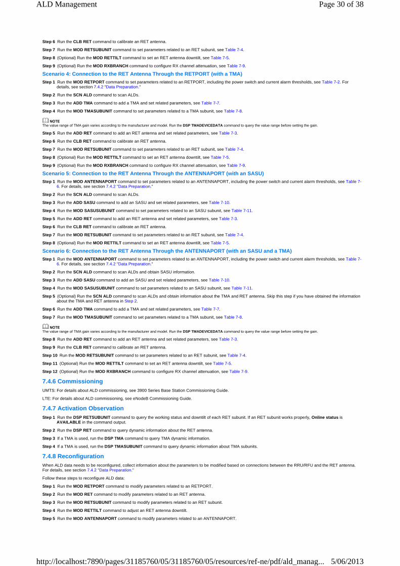
Step 6 Run the CLB RET command to calibrate an RET antenna.
Step 7 Run the MOD RETSUBUNIT command to set parameters related to an RET subunit, see Table 7-4.
Step 8 (Optional) Run the MOD RETTILT command to set an RET antenna downtilt, see Table 7-5.
Step 9 (Optional) Run the MOD RXBRANCH command to configure RX channel attenuation, see Table 7-9.
Scenario 4: Connection to the RET Antenna Through t he RETPORT (with a TMA) Step 1 Run the MOD RETPORT command to set parameters related to an RETPORT, including the power switch and current alarm thresholds, see Table 7-2. For
details, see section 7.4.2 "Data Preparation."
Step 2 Run the SCN ALD command to scan ALDs.
Step 3 Run the ADD TMA command to add a TMA and set related parameters, see Table 7-7.
Step 4 Run the MOD TMASUBUNIT command to set parameters related to a TMA subunit, see Table 7-8.
The value range of TMA gain varies according to the manufacturer and model. Run the DSP TMADEVICEDATA command to query the value range before setting the gain.
Step 5 Run the ADD RET command to add an RET antenna and set related parameters, see Table 7-3.
Step 6 Run the CLB RET command to calibrate an RET antenna.
Step 7 Run the MOD RETSUBUNIT command to set parameters related to an RET subunit, see Table 7-4.
Step 8 (Optional) Run the MOD RETTILT command to set an RET antenna downtilt, see Table 7-5.
Step 9 (Optional) Run the MOD RXBRANCH command to configure RX channel attenuation, see Table 7-9.
Scenario 5: Connection to the RET Antenna Through t he ANTENNAPORT (with an SASU) Step 1 Run the MOD ANTENNAPORT command to set parameters related to an ANTENNAPORT, including the power switch and current alarm thresholds, see Table 7-
6. For details, see section 7.4.2 "Data Preparation."
Step 2 Run the SCN ALD command to scan ALDs.
Step 3 Run the ADD SASU command to add an SASU and set related parameters, see Table 7-10.
Step 4 Run the MOD SASUSUBUNIT command to set parameters related to an SASU subunit, see Table 7-11.
Step 5 Run the ADD RET command to add an RET antenna and set related parameters, see Table 7-3.
Step 6 Run the CLB RET command to calibrate an RET antenna.
Step 7 Run the MOD RETSUBUNIT command to set parameters related to an RET subunit, see Table 7-4.
Step 8 (Optional) Run the MOD RETTILT command to set an RET antenna downtilt, see Table 7-5.
Scenario 6: Connection to the RET Antenna Through t he ANTENNAPORT (with an SASU and a TMA) Step 1 Run the MOD ANTENNAPORT command to set parameters related to an ANTENNAPORT, including the power switch and current alarm thresholds, see Table 7-
6. For details, see section 7.4.2 "Data Preparation."
Step 2 Run the SCN ALD command to scan ALDs and obtain SASU information.
Step 3 Run the ADD SASU command to add an SASU and set related parameters, see Table 7-10.
Step 4 Run the MOD SASUSUBUNIT command to set parameters related to an SASU subunit, see Table 7-11.
Step 5 (Optional) Run the SCN ALD command to scan ALDs and obtain information about the TMA and RET antenna. Skip this step if you have obtained the information about the TMA and RET antenna in Step 2.
Step 6 Run the ADD TMA command to add a TMA and set related parameters, see Table 7-7.
Step 7 Run the MOD TMASUBUNIT command to set parameters related to a TMA subunit, see Table 7-8.
The value range of TMA gain varies according to the manufacturer and model. Run the DSP TMADEVICEDATA command to query the value range before setting the gain.
Step 8 Run the ADD RET command to add an RET antenna and set related parameters, see Table 7-3.
Step 9 Run the CLB RET command to calibrate an RET antenna.
Step 10 Run the MOD RETSUBUNIT command to set parameters related to an RET subunit, see Table 7-4.
Step 11 (Optional) Run the MOD RETTILT command to set an RET antenna downtilt, see Table 7-5.
Step 12 (Optional) Run the MOD RXBRANCH command to configure RX channel attenuation, see Table 7-9.
7.4.6 Commissioning
UMTS: For details about ALD commissioning, see 3900 Series Base Station Commissioning Guide.
LTE: For details about ALD commissioning, see eNodeB Commissioning Guide.
7.4.7 Activation Observation
Step 1 Run the DSP RETSUBUNIT command to query the working status and downtilt of each RET subunit. If an RET subunit works properly, Online status is AVAILABLE in the command output.
Step 2 Run the DSP RET command to query dynamic information about the RET antenna.
Step 3 If a TMA is used, run the DSP TMA command to query TMA dynamic information.
Step 4 If a TMA is used, run the DSP TMASUBUNIT command to query dynamic information about TMA subunits.
7.4.8 Reconfiguration
When ALD data needs to be reconfigured, collect information about the parameters to be modified based on connections between the RRU/RFU and the RET antenna. For details, see section 7.4.2 "Data Preparation."
Follow these steps to reconfigure ALD data:
Step 1 Run the MOD RETPORT command to modify parameters related to an RETPORT.
Step 2 Run the MOD RET command to modify parameters related to an RET antenna.
Step 3 Run the MOD RETSUBUNIT command to modify parameters related to an RET subunit.
Step 4 Run the MOD RETTILT command to adjust an RET antenna downtilt.
Step 5 Run the MOD ANTENNAPORT command to modify parameters related to an ANTENNAPORT.
Page 30 of 38ALD Management
5/06/2013http://localhost:7890/pages/31185760/05/31185760/05/resources/ref-ne/pdf/ald_manag...
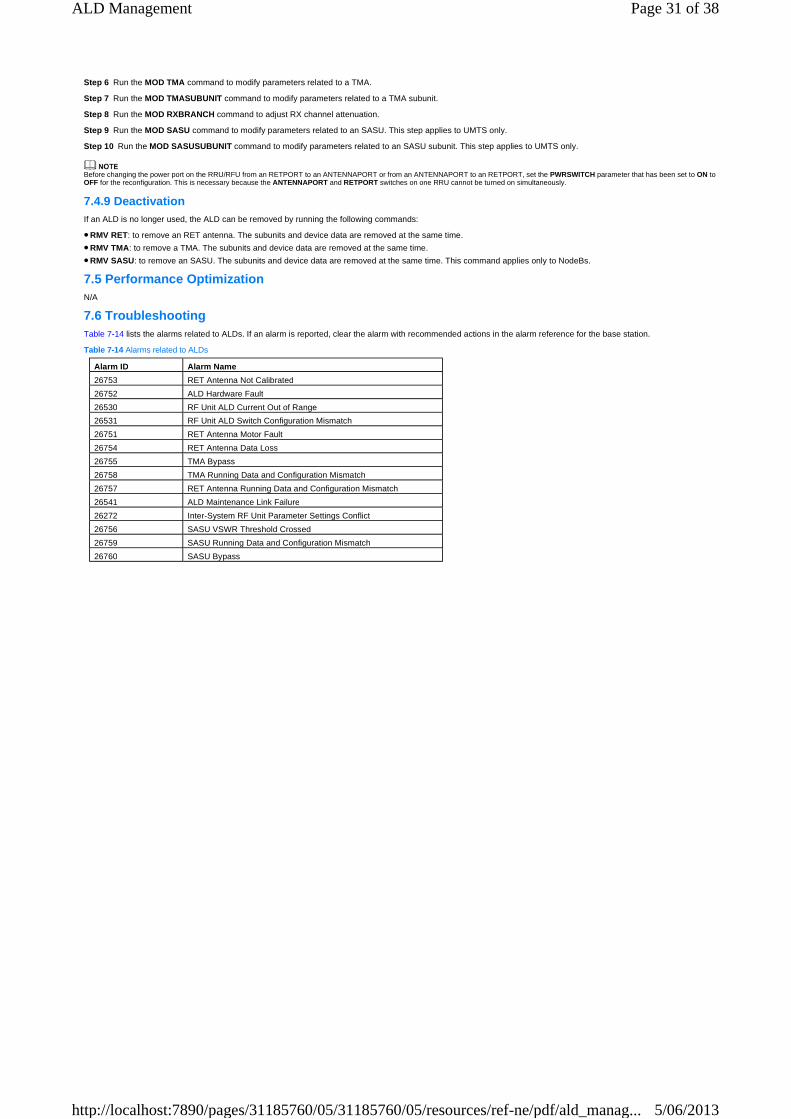
Step 6 Run the MOD TMA command to modify parameters related to a TMA.
Step 7 Run the MOD TMASUBUNIT command to modify parameters related to a TMA subunit.
Step 8 Run the MOD RXBRANCH command to adjust RX channel attenuation.
Step 9 Run the MOD SASU command to modify parameters related to an SASU. This step applies to UMTS only.
Step 10 Run the MOD SASUSUBUNIT command to modify parameters related to an SASU subunit. This step applies to UMTS only.
Before changing the power port on the RRU/RFU from an RETPORT to an ANTENNAPORT or from an ANTENNAPORT to an RETPORT, set the PWRSWITCH parameter that has been set to ON to OFF for the reconfiguration. This is necessary because the ANTENNAPORT and RETPORT switches on one RRU cannot be turned on simultaneously.
7.4.9 Deactivation
If an ALD is no longer used, the ALD can be removed by running the following commands:
RMV RET: to remove an RET antenna. The subunits and device data are removed at the same time.
RMV TMA: to remove a TMA. The subunits and device data are removed at the same time.
RMV SASU: to remove an SASU. The subunits and device data are removed at the same time. This command applies only to NodeBs.
7.5 Performance Optimization
N/A
7.6 Troubleshooting
Table 7-14 lists the alarms related to ALDs. If an alarm is reported, clear the alarm with recommended actions in the alarm reference for the base station.
Table 7-14 Alarms related to ALDs
Alarm ID Alarm Name
26753 RET Antenna Not Calibrated
26752 ALD Hardware Fault
26530 RF Unit ALD Current Out of Range
26531 RF Unit ALD Switch Configuration Mismatch
26751 RET Antenna Motor Fault
26754 RET Antenna Data Loss
26755 TMA Bypass
26758 TMA Running Data and Configuration Mismatch
26757 RET Antenna Running Data and Configuration Mismatch
26541 ALD Maintenance Link Failure
26272 Inter-System RF Unit Parameter Settings Conflict
26756 SASU VSWR Threshold Crossed
26759 SASU Running Data and Configuration Mismatch
26760 SASU Bypass
�
�
�
Page 31 of 38ALD Management
5/06/2013http://localhost:7890/pages/31185760/05/31185760/05/resources/ref-ne/pdf/ald_manag...

8 Engineering Guidelines (GSM) 8.1 When to Use ALD Management
It is recommended that ALD management be used when ALDs have been installed and the ALDs comply with the AISG protocol. The AISG protocol has two versions, AISG v1.1 and AISG v2.0, both supported in SRAN7.0.
8.2 Information to Be Collected
N/A
8.3 Network Planning
N/A
8.4 Deploying ALD Management
8.4.1 Deployment Requirements
N/A
8.4.2 Data Preparation
Introduction This section includes only key parameters, not parameters in all scenarios.
Data sources of key parameters include the following:
Radio network planning (internal planning): The parameter value comes from the radio network plan, facilitating resource management on the current NE.
Radio network planning (negotiated with the peer): The parameter value comes from the radio network plan. The NE negotiates this value with the peer device to ensure successful interworking.
Transport network planning (internal planning): The parameter value comes from the transport network plan, facilitating resource management on the current NE.
Transport network planning (negotiated with the peer): The parameter value comes from the transport network plan. The NE negotiates this value with the peer device to ensure successful interworking.
Equipment planning: The parameter value comes from the equipment plan.
Engineering design: The parameter value comes from the algorithm or function design.
Default/recommended value: The parameter uses the default or recommended value, and the recommended value is preferential. The default or recommended value can be used in most scenarios and adjusted for a specific scenario.
N/A: The parameter value is not required.
ALD data configuration varies according to scenarios. Different scenarios vary when control signals are sent to an RET antenna through different RRU/RFU ports and when a TMA is used.
The scenarios are as follows:
Scenario 1: connection to the RET antenna through the RETPORT
Scenario 2: connection to the RET antenna through the ANTENNAPORT
Scenario 3: connection to the RET antenna through the ANTENNAPORT (with a TMA)
Scenario 4: connection to the RET antenna through the RETPORT (with a TMA)
Generic Data For details about generic data, see section 7.4.2 "Data Preparation."
Scenario 1: Connection to the RET Antenna Through t he RETPORT Table 8-1 describes the parameters that must be set to configure an RETPORT.
Table 8-1 Key parameters related to the RETPORT
Table 8-2 describes the parameters that must be set to configure an RET antenna.
Table 8-2 Key parameters related to the RET antenna
Parameter Name
Parameter ID Setting Description Source
RET ALD Power Switch
PwrSwitchRET Set this parameter to ON when an RET antenna is used. The default value is OFF.
Equipment plan
RET ALD Current Alarm Threshold Type
THRESHOLDTYPERET Set this parameter based on the site conditions.
Engineering design
RET ALD Under Current Occur Threshold(mA)
UnderCurAlmThdRET Set these parameters only if the THRESHOLDTYPERET parameter is set to UER_SELF_DEFINE. Set these parameters as required. For details, see section 8.4.3 "Precautions."
Engineering design
RET ALD Under Current Clear Threshold(mA)
UnderCurClrThdRET Engineering design
RET ALD Over Current Occur Threshold(mA)
OverCurAlmThdRET Engineering design
RET ALD Over Current Clear Threshold(mA)
OverCurClrThdRET Engineering design
Parameter Name Parameter ID Setting Description Source
Device No. DEVICENO This parameter specifies the device number. The device number of each ALD in a BTS must be unique. The DEVICENO parameter value of the RET antenna must differ from that of the TMA.
Equipment plan
Device Name DEVICENAME This parameter identifies the RET antenna. The format of the value is site_sector+port+device type_network type. For details, see the device name-related
Engineering design
�
�
�
�
�
�
�
�
�
�
�
�
Page 32 of 38ALD Management
5/06/2013http://localhost:7890/pages/31185760/05/31185760/05/resources/ref-ne/pdf/ald_manag...
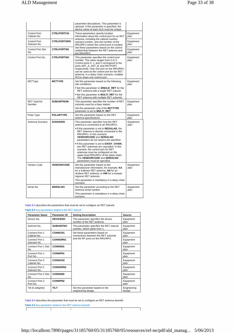
Table 8-3 describes the parameters that must be set to configure an RET subunit.
Table 8-3 Key parameters related to the RET subunit
Table 8-4 describes the parameter that must be set to configure an RET antenna downtilt.
Table 8-4 Key parameter related to the RET antenna downtilt
parameter descriptions. This parameter is optional. If this parameter is specified, the device name of each ALD must be unique.
Control Port Cabinet No.
CTRLPORTCN These parameters specify location information about the control port for an RET antenna, including the cabinet number, subrack number, and slot number of the RRU/RFU where the control port is located. Set these parameters based on the control relationship between the RET antenna and the RRU/RFU.
Equipment plan
Control Port Subrack No.
CTRLPORTSRN Equipment plan
Control Port Slot No.
CTRLPORTSN Equipment plan
Control Port No. CTRLPORTNO This parameter specifies the control port number. The value ranges from 0 to 2. Control ports 0, 1, and 2 correspond to the ports ANT_A, ANT_B, and RETPORT, respectively. Only one port on the RRU/RFU can be used as the control port for the RET antenna. In a daisy chain scenario, multiple RCUs share one control port.
Equipment plan
RETType RETTYPE Set this parameter based on the following site conditions:
Set this parameter to SINGLE_RET for the RET antenna with a single RET subunit.
Set this parameter to MULTI_RET for the RET antenna with multiple RET subunits.
Equipment plan
RET SubUnit Number
SUBUNITNUM This parameter specifies the number of RET subunits used by a base station.
Set this parameter only if the RETTYPE parameter is set to MULTI_RET.
Equipment plan
Polar Type POLARTYPE Set this parameter based on the RET antenna specifications.
Equipment plan
Antenna Scenario SCENARIO This parameter specifies how the RET antenna is connected to an RRU/RFU.
If this parameter is set to REGULAR , the RET antenna is directly connected to the RRU/RFU. In this scenario, VENDORCODE and SERIALNO parameters do not need to be specified.
If this parameter is set to DAISY_CHAIN , two RET antennas are cascaded. In this scenario, the control port for RET antennas must be configured on the upper-level RRU/RFU of the daisy chain. The VENDORCODE and SERIALNO parameters must be specified.
Equipment plan
Vendor Code VENDORCODE Set this parameter based on the manufacturer information, for example, KA for a Kathrein RET antenna, AN for an Andrew RET antenna, or HW for a Huawei Agisson RET antenna.
This parameter is mandatory in a daisy chain scenario.
Equipment plan
Serial No. SERIALNO Set this parameter according to the RET antenna serial number.
This parameter is mandatory in a daisy chain scenario.
Equipment plan
Parameter Name Parameter ID Setting Description Source
Device No. DEVICENO This parameter specifies the device number of the RET antenna.
Equipment plan
SubUnit No. SUBUNITNO This parameter specifies the RET subunit number, which starts from 1.
Equipment plan
Connect Port 1 Cabinet No.
CONNCN1 Set these parameters based on connections between the RET subunits and the RF ports on the RRU/RFU.
Equipment plan
Connect Port 1 Subrack No.
CONNSRN1 Equipment plan
Connect Port 1 Slot No.
CONNSN1 Equipment plan
Connect Port 1 Port No.
CONNPN1 Equipment plan
Connect Port 2 Cabinet No.
CONNCN2 Equipment plan
Connect Port 2 Subrack No.
CONNSRN2 Equipment plan
Connect Port 2 Slot No.
CONNSN2 Equipment plan
Connect Port 2 Port No.
CONNPN2 Equipment plan
Tilt (0.1degree) TILT Set this parameter based on the engineering design.
Engineering design
�
�
�
�
Page 33 of 38ALD Management
5/06/2013http://localhost:7890/pages/31185760/05/31185760/05/resources/ref-ne/pdf/ald_manag...

Scenario 2: Connection to the RET Antenna Through t he ANTENNAPORT For parameters that must be set to configure an RET antenna, RET subunit, and RET antenna downtilt in this scenario, see Table 8-2, Table 8-3, and Table 8-4.
Table 8-5 describes the parameters that must be set to configure an ANTENNAPORT. This table assumes that ANT_A is a control port. When any other ANTENNAPORT is the control port, the key parameters can be similarly configured. For example, when ANT_B is the control port, the parameter ID PwrSwitchB is configured accordingly.
Table 8-5 Key parameters related to the ANTENNAPORT
Scenario 3: Connection to the RET Antenna Through t he ANTENNAPORT (with a TMA) For parameters that must be set to configure an RET antenna, RET subunit, and RET antenna downtilt in this scenario, see Table 8-2, Table 8-3, and Table 8-4.
For parameters that must be set to configure an ANTENNAPORT in this scenario, see Table 8-5.
Table 8-6 describes the parameters that must be set to configure a TMA.
Table 8-6 Key parameters related to the TMA
Table 8-7 describes the parameters that must be set to configure a TMA subunit.
Table 8-7 Key parameters related to the TMA subunit
Parameter Name Parameter ID Setting Description Source
Tilt (0.1degree) TILT Set this parameter based on the engineering design.
Engineering design
Parameter Name Parameter ID Setting Description Source
ANT_A ALD Power Switch
PwrSwitchA Set this parameter to ON when an ALD is used. The default value is OFF.
If this parameter is set to ON, current alarm thresholds for this port must be specified.
Equipment plan
ANT_A ALD Current Alarm Threshold Type
ChkModA Set this parameter based on the site conditions. For details, see Table 7-12.
Engineering design
ANT_A ALD Over Current Occur Threshold(mA)
OverCurAlmThdA Set these parameters only if the ChkModA parameter is set to UER_SELF_DEFINE. Set these parameters as required. For details, see section 8.4.3 "Precautions."
Engineering design
ANT_A ALD Over Current Clear Threshold(mA)
OverCurClrThdA Engineering design
ANT_A ALD Under Current Occur Threshold(mA)
UnderCurAlmThdA Engineering design
ANT_A ALD Under Current Clear Threshold(mA)
UnderCurClrThdA Engineering design
Parameter Name
Parameter ID Setting Description Source
Device No. DEVICENO The device number of each ALD in a BTS must be unique. The DEVICENO parameter value of the RET antenna must differ from that of the TMA.
Equipment plan
Device Name DEVICENAME This parameter identifies the RET antenna. The format of the value is site_sector+port+device type_network type. For details, see the device name-related parameter descriptions. This parameter is optional. If this parameter is specified, the device name of each ALD must be unique.
Engineering design
TMA Power Supply Type
PWRSUPPLYTYPE This parameter specifies the power supply type of the TMA. Set this parameter based on the specifications provided by the TMA manufacturer.
Equipment plan
Control Port Cabinet No.
CTRLPORTCN These parameters specify location information about the control port, including the cabinet number, subrack number, and slot number of the RRU/RFU where the control port is located. Set these parameters based on control relationship between the TMA and the RRU/RFU.
Equipment plan
Control Port Subrack No.
CTRLPORTSRN Equipment plan
Control Port Slot No.
CTRLPORTSN Equipment plan
TMA Subunit Number
SUBUNITNUM Set this parameter based on the site conditions. Generally, the value is 2.
Equipment plan
Vendor code VENDORCODE Set this parameter to the actual TMA manufacturer code.
Equipment plan
Serial No. SERIALNO Set this parameter to the actual TMA serial number.
Equipment plan
Parameter Name Parameter ID Setting Description Source
Device No. DEVICENO This parameter specifies the device number of the TMA.
Equipment plan
SubUnit No. SUBUNITNO This parameter specifies the TMA subunit number.
Equipment plan
Connect Port Cabinet No.
CONNCN Set these parameters based on connections between the TMA and the RF port on the RRU/RFU.
Equipment plan
Page 34 of 38ALD Management
5/06/2013http://localhost:7890/pages/31185760/05/31185760/05/resources/ref-ne/pdf/ald_manag...

Table 8-8 describes the parameters that must be set to configure RX channel attenuation.
Table 8-8 Key parameters related to RX channel attenuation
Scenario 4: Connection to the RET Antenna Through t he RETPORT (with a TMA) For parameters that must be set to configure an RETPORT, RET antenna, RET subunit, and RET antenna downtilt in this scenario, see Table 8-1, Table 8-2, Table 8-3, and Table 8-4.
For parameters that must be set to configure a TMA, TMA subunit, and RX channel attenuation in this scenario, see Table 8-6, Table 8-7, and Table 8-8.
8.4.3 Precautions
Section 7.4.3 "Precautions" describes the common precautions for GSM, UMTS, and LTE. The GSM-specific precautions are described as follows:
The common TMA does not support the AISG protocol. To configure a common TMA, you only need to run the SET BTSRXUBP command to turn on the power switch, set current alarm thresholds, and configure the RX channel attenuation based on the network plan. For data preparation details for turning on the power switch and setting the current alarm thresholds, see Table 8-5. For data preparation details for configuring the RX channel attenuation, see Table 8-8.
After subunits are added to an AISG1.1-based TMA, all TMA subunits start to work only after you run the STR BTSALDSCAN command.
Connect Port Subrack No.
CONNSRN Equipment plan
Connect Port Slot No.
CONNSN Equipment plan
Connect Port Port No.
CONNPN Equipment plan
Mode MODE The TMA subunit supports two working modes, normal mode and bypass modes:
In normal mode, the TMA amplifies uplink signals.
In bypass mode, the TMA subunit works as a straight-through feeder. It does not amplify uplink signals.
The default value is NORMAL .
Equipment plan
Gain (0.25db) GAIN Set this parameter based on the engineering design. The gain value range supported by the TMA varies according to the manufacturer and model. Run the DSP BTSTMADEVICEDATA command to query the value range before setting the gain. If the gain is fixed, this parameter is optional, or you can set this parameter to its actual gain value.
Engineering design
Parameter Name
Parameter ID Setting Description Source
Antenna Tributary 1 Flag
HAVETT1 This parameter specifies whether a TMA is connected to RF port ANT_A. If a TMA is connected, set this parameter to YES.
Equipment plan
Antenna Tributary 1 Factor
ATTENFACTOR1 Set this parameter based on the site conditions after the TMA is installed. This parameter can be set only if the RXUTYPE parameter is set to DRRU or DRFU.
Engineering design
Antenna Tributary 1 Factor
MRRUATTENFACTOR1 Set this parameter based on the site conditions after the TMA is installed. This parameter can be set only if the RXUTYPE parameter is not set to DRRU or DRFU.
Engineering design
Antenna Tributary 2 Flag
HAVETT2 This parameter specifies whether a TMA is connected to RF port ANT_B. If a TMA is connected, set this parameter to YES.
Equipment plan
Antenna Tributary 2 Factor
ATTENFACTOR2 Set this parameter based on the site conditions after the TMA is installed. This parameter can be set only if the RXUTYPE parameter is set to DRRU or DRFU.
Engineering design
Antenna Tributary 2 Factor
MRRUATTENFACTOR2 Set this parameter based on the site conditions after the TMA is installed. This parameter can be set only if the RXUTYPE parameter is not set to DRRU or DRFU.
Engineering design
Antenna Tributary 3 Flag
HAVETT3 This parameter specifies whether a TMA is connected to RF port ANT_C. If a TMA is connected, set this parameter to YES.
Equipment plan
Antenna Tributary 3 Factor
MRRUATTENFACTOR3 Set this parameter based on the site conditions after the TMA is installed. This parameter can be set only if the RXUTYPE parameter is set to MRRU or GRRU.
Engineering design
Antenna Tributary 4 Flag
HAVETT4 This parameter specifies whether a TMA is connected to RF port ANT_D. If a TMA is connected, set this parameter to YES.
Equipment plan
Antenna Tributary 4 Factor
MRRUATTENFACTOR4 Set this parameter based on the site conditions after the TMA is installed. This parameter can be set only if the RXUTYPE parameter is set to MRRU or GRRU.
Engineering design
�
�
Page 35 of 38ALD Management
5/06/2013http://localhost:7890/pages/31185760/05/31185760/05/resources/ref-ne/pdf/ald_manag...

When the current alarm threshold type is user-defined, set current alarm thresholds based on the actual ALD type. Pay attention to the following restrictions:
User-defined current alarm thresholds must meet the requirements: Under Current Occur Threshold < Under Current Clear Threshold < Over Current Clear Threshold < Over Current Occur Threshold.
Generally, the Under Current Occur Threshold is set to 20% to 30% of the device rated operating current, and the Under Current Clear Threshold is set to about 20 mA greater than the Under Current Occur Threshold. The Over Current Occur Threshold is set to 150% to 200% of the device rated operating current, and the Over Current Clear Threshold is set to about 50 mA less than the Over Current Occur Threshold.
If RET antennas are connected in a non-regular scenario, the Under Current Occur Threshold is set to 20% to 30% of the total rated current of all ALDs controlled by the RRU. The Over Current Occur Threshold is set to a value that is 150% to 200% of the total rated current of all ALDs controlled by the RRU.
If configured ALD model is not recommended by Huawei, the Under Current Occur Threshold is set to 20% to 30% of the total rated current of all ALDs controlled by the RRU. The Over Current Occur Threshold is set to 150% to 200% of the total rated current of all ALDs controlled by the RRU.
There are three user-define types: UER_SELF_DEFINE1, UER_SELF_DEFINE2, and UER_SELF_DEFINE3. Generally, the value is UER_SELF_DEFINE1.
8.4.4 Initial Configuration on the GUI
Configuring a Single Base Station Configure ALDs using the data prepared in section 8.4.2 "Data Preparation." For details, see 3900 Series Base Station Initial Configuration Guide and navigate in the following sequence: GBTS Initial Configuration > Creating a GBTS (Topology Mode, 3900 Series Base Stations) > Configuring GBTS Device Data (3900 Series Base Stations) > Configuring ALDs > Procedure.
When you navigate in the document, locate the correct node based on the type of the base station controller connected to the base station.
Configuring Base Stations in Batches Customize a template on a base station where ALDs have been configured, and save this template. Prepare a summary data file by referencing the user-defined template. Configure eNodeBs in batches based on the summary data file.
For details, see 3900 Series Base Station Initial Configuration Guide and navigate in the following sequence: GBTS Initial Configuration > Creating GBTSs (by Using a Summary Data File).
When you navigate in the document, locate the correct node based on the type of the base station controller connected to the base station.
8.4.5 Initial Configuration on a Single Base Station Using MML Commands
Scenario 1: Connection to the RET Antenna Through t he RETPORT Step 1 Run the SET BTSRXUBP command to set parameters related to an RETPORT, including the power switch and current alarm thresholds, see Table 8-1. For
details, see section 8.4.2 "Data Preparation."
Step 2 Run the STR BTSALDSCAN command to scan ALDs.
Step 3 Run the ADD BTSRET command to add an RET antenna and set related parameters, see Table 8-2.
Step 4 Run the CLB BTSRET command to calibrate an RET antenna.
Step 5 Run the MOD BTSRETSUBUNIT command to set parameters related to an RET subunit, see Table 8-3.
Step 6 (Optional) Run the MOD BTSRETTILT command to set an RET antenna downtilt, see Table 8-4.
Scenario 2: Connection to the RET Antenna Through t he ANTENNAPORT Step 1 Run the SET BTSRXUBP command to set parameters related to an ANTENNAPORT, including the power switch and current alarm thresholds, see Table 8-5. For
details, see section 8.4.2 "Data Preparation."
Step 2 Run the STR BTSALDSCAN command to scan ALDs.
Step 3 Run the ADD BTSRET command to add an RET antenna and set related parameters, see Table 8-2.
Step 4 Run the CLB BTSRET command to calibrate an RET antenna.
Step 5 Run the MOD BTSRETSUBUNIT command to set parameters related to an RET subunit, see Table 8-3.
Step 6 (Optional) Run the MOD BTSRETTILT command to set an RET antenna downtilt, see Table 8-4.
Scenario 3: Connection to the RET Antenna Through t he ANTENNAPORT (with a TMA) Step 1 Run the SET BTSRXUBP command to set parameters related to an ANTENNAPORT, including the power switch and current alarm thresholds, see Table 8-5. For
details, see section 8.4.2 "Data Preparation."
Step 2 Run the STR BTSALDSCAN command to scan ALDs.
Step 3 Run the ADD BTSTMA command to add a TMA and set related parameters, see Table 8-6.
Step 4 Run the MOD BTSTMASUBUNIT command to set parameters related to a TMA subunit, see Table 8-7.
The value range of TMA gain varies according to the manufacturer and model. Run the DSP BTSTMADEVICEDATA command to query the value range before setting the gain.
Step 5 Run the ADD BTSRET command to add an RET antenna and set related parameters, see Table 8-2.
Step 6 Run the CLB BTSRET command to calibrate an RET antenna.
Step 7 Run the MOD BTSRETSUBUNIT command to set parameters related to an RET subunit, see Table 8-3.
Step 8 (Optional) Run the MOD BTSRETTILT command to set an RET antenna downtilt, see Table 8-4.
Step 9 (Optional) Run the SET BTSRXUBP command to configure RX channel attenuation, see Table 8-8.
Scenario 4: Connection to the RET Antenna Through t he RETPORT (with a TMA)
Step 1 Run the SET BTSRXUBP command to set parameters related to an RETPORT, including the power switch and current alarm thresholds, see Table 8-1. For details, see section 8.4.2 "Data Preparation."
Step 2 Run the STR BTSALDSCAN command to scan ALDs.
Step 3 Run the ADD BTSTMA command to add a TMA and set related parameters, see Table 8-6.
Step 4 Run the MOD BTSTMASUBUNIT command to set parameters related to a TMA subunit, see Table 8-7.
The value range of TMA gain varies according to the manufacturer and model. Run the DSP BTSTMADEVICEDATA command to query the value range before setting the gain.
Step 5 Run the ADD BTSRET command to add an RET antenna and set related parameters, see Table 8-2.
Step 6 Run the CLB BTSRET command to calibrate an RET antenna.
Step 7 Run the MOD BTSRETSUBUNIT command to set parameters related to an RET subunit, see Table 8-3.
Step 8 (Optional) Run the MOD BTSRETTILT command to set an RET antenna downtilt, see Table 8-4.
�
�
�
�
�
Page 36 of 38ALD Management
5/06/2013http://localhost:7890/pages/31185760/05/31185760/05/resources/ref-ne/pdf/ald_manag...

Step 9 (Optional) Run the SET BTSRXUBP command to configure RX channel attenuation, see Table 8-8.
8.4.6 Commissioning
For details about ALD commissioning, see 3900 Series Base Station Commissioning Guide.
8.4.7 Activation Observation
Step 1 Run the DSP BTSRETSUBUNIT command to query the working status and downtilt of each RET subunit. If an RET subunit works properly, Online Status is AVAILABLE in the command output.
Step 2 Run the DSP BTSRET command to query dynamic information about the RET antenna.
Step 3 If a TMA is used, run the DSP BTSTMA command to query TMA dynamic information.
Step 4 If a TMA is used, run the DSP BTSTMASUBUNIT command to query dynamic information about TMA subunits.
8.4.8 Reconfiguration
When you need to reconfigure ALD data, collect information about the parameters to be modified based on connections between the RRU/RFU and the RET antenna. For details, see section 8.4.2 "Data Preparation."
Step 1 Run the SET BTSRXUBP command to modify parameters related to an RETPORT.
Step 2 Run the MOD BTSRET command to modify parameters related to an RET antenna.
Step 3 Run the MOD BTSRETSUBUNIT command to modify parameters related to an RET subunit.
Step 4 Run the MOD BTSRETTILT command to adjust an RET antenna downtilt.
Step 5 Run the SET BTSRXUBP command to modify parameters related to an ANTENNAPORT.
Step 6 Run the MOD BTSTMA command to modify parameters related to a TMA.
Step 7 Run the MOD BTSTMASUBUNIT command to modify parameters related to a TMA subunit.
Step 8 Run the SET BTSRXUBP command to adjust RX channel attenuation.
Before changing the power port on the RRU/RFU from an RETPORT to an ANTENNAPORT or from an ANTENNAPORT to an RETPORT, set the PwrSwitchRET or PwrSwitchA parameter that has been set to ON to OFF for the reconfiguration. This is necessary because the ANTENNAPORT and RETPORT switches on one RRU cannot be turned on simultaneously.
8.4.9 Deactivation
If an ALD is no longer used, the ALD can be removed by running the following commands:
RMV BTSRET: to remove an RET antenna. The subunits and device data are removed at the same time.
RMV BTSTMA : to remove a TMA. The subunits and device data are removed at the same time.
8.5 Performance Optimization
N/A
8.6 Troubleshooting
Table 8-9 lists the alarms related to ALDs. If an alarm is reported, clear the alarm with recommended actions in the alarm reference of the BSC.
Table 8-9 Alarms related to ALDs
Alarm ID Alarm Name
26753 RET Antenna Not Calibrated
26752 ALD Hardware Fault
26530 RF Unit ALD Current Out of Range
26531 RF Unit ALD Switch Configuration Mismatch
26751 RET Antenna Motor Fault
26754 RET Antenna Data Loss
26755 TMA Bypass
26758 TMA Running Data and Configuration Mismatch
26757 RET Antenna Running Data and Configuration Mismatch
26541 ALD Maintenance Link Failure
26272 Inter-System RF Unit Parameter Settings Conflict
�
�
Page 37 of 38ALD Management
5/06/2013http://localhost:7890/pages/31185760/05/31185760/05/resources/ref-ne/pdf/ald_manag...

9 Reference Documents [1] Overview of the Antenna System
[2] eNodeB Initial Configuration Guide
[3] 3900 Series Base Station Initial Configuration Guide
[4] 3900 Series Base Station Commissioning Guide
[5] eNodeB Commissioning Guide
[6] RRU3942 Hardware Description
[7] RRU3841 Hardware Description
[8] Glossary
Page 38 of 38ALD Management
5/06/2013http://localhost:7890/pages/31185760/05/31185760/05/resources/ref-ne/pdf/ald_manag...