Embed Size (px)
Citation preview

Please read and save these instructions.
AK-200BK
KEGERATOR OWNER'S
MANUAL
AK-200 SERIES

1
CONTENTS
The rating data indicated on the energy label is based on the testing condition of installing the un-extendedair exhaust duct without adaptor A & B (The duct andthe adaptor A & B are listed in the accessories chartof the Instruction Manual).
NOTE
................................................................................................................................................................................................
......................................................................................................................
455
Installing the CastersInstalling the Beer TapInstalling the GuardrailInstalling the CO Regulator and the CO Cylinder2 2
Tapping the Beer Keg – Installing Keg Tap
.........................................................................................................................................................................................................................................................................................................................................................................
....................................................................................................................................................................
ASSEMBLY INSTRUCTIONS
SAFETY PRECAUTIONSImportant Safety Precautions of CO 2
Proper LocationUse of Extension Cords
(Carbon Dioxide) Gas
Cleaning & MaintenanceStorage & care
.......................................................................................................................................................................................................................................................
OPERATING YOUR KEGGER MEISTER
SPECIAL SAFETY INFORMATION....................................................................................................SPECIAL SAFETY INFORMATION
Quick Assembly Instructions ................................................................................................QUICK ASSEMBLY INSTRUCTIONS
Limited Manufacturer's Warranty......................................................................................LIMITED MANUFACTURER'S WARRANTY
66778
1010
9...........................................................................
11.....................................................................................11
13
13
.................................................................................
16
16
................................................................................................ 5
......................................................................................................... 2
OPERATING YOUR KEGERATOR ...........................................................................
Special Safety Information
.................................................................................
:
2
SAFETY PRECAUTIONS
Read all of the instructions before using this appliance. When using this
appliance, always exercise basic safety precautions, including the following:
Use this appliance only for its intended purpose as described in this operation
manual.
This appliance must be properly installed in accordance with the installation
instructions before it is used. See the installation section for more details.
This appliance must be connected to a proper electrical outlet with the correct
electrical supply.
Proper grounding must be ensured to reduce the risk of shock and fire. Do not
cut or remove the grounding pin! If you do not have a three-prong electric
receptacle outlet in the wall, have a certified electrician install the proper outlet.
The wall receptacle must be properly grounded.
Never unplug your appliance by pulling on the power cord. Always grasp the
plug firmly and pull straight out from the outlet.
Immediately replace worn power cords, loose plugs and power outlets. If the
supply cord is damaged, it must be replaced by the manufacturer or its service
agent or a similarly qualified person in order to avoid a hazard.
To reduce the risk of electric shock or fire, do not use extension cords or
adapters to connect the unit to an electrical power source.
Unplug your appliance before cleaning or making any repairs.
We suggest that a certified technician perform the service if for any reason this
product requires service.
If your old appliance is being discarded, we recommend that you remove the
door and leave the shelves in place. This will reduce the possibility of danger to
children.
This appliance should not be recessed or built into an enclosed cabinet. It is
designed for freestanding installation only.
Do not operate your appliance in the presence of explosive fumes.
Do not tamper with the controls.
Do not operate this appliance when parts are missing or broken.
Do not use this appliance for commercial use.
This appliance is designed for indoor use only and should not be used outdoors.
To reduce the risk of injury, do not allow children to play in or on the appliance.
Close supervision is necessary when the appliance is used near children.
The appliance door must be closed during operation. Do not leave the door
open when children are near the dispenser.
Do not run cord over carpeting or other heat insulators. Do not cover the cord.
Keep cord away from traffic areas, and do not submerge in water. DO NOT
attempt to operate this unit with a damaged cord or plug.
DO NOT roll the kegerator with loaded beer kegs on carpet floor.
1.
2.
3.
4.
5.
6.
7.
8.
9.
10.
11.
12.
13.
14.
15.
16.
17.
18.
19.
20.

3
SAFETY PRECAUTIONS
This appliance is not intended for use by young children or infirm persons
without supervision.
This appliance is NOT A TOY!
Young children should be supervised to ensure that they do not play with this
appliance.
When transporting the refrigerator, keep the unit in the upright position. Do not
tilt the appliance beyond 45° or place the unit in an upside down position.
21.
22.
23.
24.

4
SAFETY PRECAUTIONS
Important Safety Precautions of CO2
(Carbon Dioxide) Gas
Co2 gas can be dangerous! CO cylinders contain high-pressure compressed 2
gas, which can be hazardous if not handled properly. Make sure you read and
understand all the procedures for the CO cylinders before installation.2
Always connect the CO cylinder to a regulator! Failure to do so may cause an 2
explosion resulting in possible death or injury when the cylinder valve is opened.
Never connect the CO cylinder directly to the product container.2
Always follow the correct procedures when changing cylinders.
Never drop or throw a CO cylinder.2
Always keep CO cylinders away from heat. Store extra cylinders at a cool 2
place (preferably lower than 70° F). Securely fasten with a chain in an upright
position when storing.
Always ventilate and leave the area immediately if CO leakage has occurred!2
There are two safety devices in the pressure system in the form of a valve. One
safety feature is on the CO bottle. The second is on the regulator.2
Never attempt to refill CO cylinders yourself. CO tanks can be refilled at 2 2
locations such as welding supply shops, party stores, fire supply shops, or
where kegs are purchased.
1.
2.
3.
4.
5.
6.
7.
8.
9.
Beer
Dispenser
Tower
Beer Line
Keg
Coupler
Beer Keg
(Not Included)
High-Pressure Valve
CO Bottle2
Shut Off Safely
CO Line2
Double-Gauge
CO Regulator2
Low Pressure
Valve
24.75"
23"
13.5"
23"
CO Tank2

5
SAVE THESE INSTRUCTIONS
For Future Use
Risk of child entrapment! Before throwing away your old appliance:● Take off the doors.● Leave the shelves or other accessories in place so that children may not easily become trapped inside.
(Note: If the refrigerator has been placed in a horizontal or tilted position for any
period of time, please wait at least 24 hours before plugging the unit in.)
Proper Location
�To ensure that your kegerator works to the maximum efficiency it was
designed for, keep it in a location where there is proper air circulation and
electrical outlets.
�Choose a location where the kegerator will be away from heat and will not
be exposed to direct sunlight.
�This kegerator is designed for indoor use only -- it should not be used
outdoors.
�This kegerator is a freestanding design and should not be placed in a built-in
or recessed area.
�Kegerator unit dimensions:
21.3” W x 33.20” H (with casters) x 26.60” D
�The following dimensions are recommended for clearances around the kegerator:
Sides ……………………5” (12 cm)
Back ……………………5” (12 cm)
DANGER!
Use of Extension Cords�Always avoid using an extension cord because of potential safety hazards in
certain conditions. If it is necessary to use an extension cord, use only a 3-wire
extension cord that has a 3-blade grounding plug. And use the cord with No. 14
AWG minimum size and rated not less than 1875watts.
Assembly Instructions�Read assembly instructions carefully to ensure that you understand all installation
instructions before installing the kegerator. If after completing the process
ASSEMBLY INSTRUCTIONS

6
you are still unsure whether the kegerator has been properly installed, we
recommend that you contact a qualified installer.
�Note: Allow the kegerator to stand in an upright position for at least 8 hours
before plugging in the unit. This is very important! Once the unit is laid on its side,
the refrigerant in the refrigeration system is shifted. The refrigerant in the
refrigeration system needs to stabilize before the unit is turned on.
Installing the Casters
Follow the steps below to install the casters.
Empty the inside of the cabinet completely and lay the kegerator down on its side.
We recommend that you place a piece of cardboard or cloth underneath
the cabinet to prevent dents or scratches.
1.
Note: Two of the casters include locking
mechanisms to ensure the unit does not
slide on hard floors. These two locking
casters should be fastened at the front
end of the unit, with the unlocked casters
fastened on the rear end.
2.
3.
Insert the casters into the holes on the bottom corners of the cabinet. Tighten
each caster by turning the head of the bolts clockwise with a wrench. (Not
provided in the kit.)
Once all four casters have been
tightened, stand the cabinet in its
upright position.
Installing the Beer Tap
Follow the steps below to install the beer tap.
There are notches on the bottom of the draft arm
assembly that line up with grooves inside the
opening on the top of the kegerator. Align
simply lock it into place.U
s11 &12 )
Beer
Dispenser
Tower
Beer Duct
Guard Rail
ASSEMBLY INSTRUCTIONS
the draft arm with the opening on the top of the unit, then
place inside and twist until secure. No screws are
black gasket for assembly. (See Illustrations C &
D on page )
necessary, se the thin

Also, See Illustrations E & F on pages 12 & 13, showing the hose connections to CO 2regulator and the regulator to the beer tap.
Installing the Guardrail
Follow the steps below to install the guardrail.
1. Place the guardrail on top of the cabinet.
2. Align all support feet of the guardrail with the holes on the top of the unit.
Installing the CO Regulator and 2
the CO Cylinder2
Follow these steps to safely install the CO 2
regulator and CO cylinder. You must read 2
and understand the following procedures
for the CO cylinders before installation.2
NOTE: Your CO cylinder has DOT (USA2
Department of Transportation) approval
however the cylinder has been shipped
empty to avoid any possible accidents
during transportation. When you purchase
the first keg of beer, you must also have
your CO cylinder filled at your local 2
supplier. (See page 4, item 9 for
suggested locations within your community.)
Install the CO gas line tube to the regulator by attaching one end of the tube to
the hose barb connection on the CO regulator. (See Illustration B, on page 6)
Insert the special washer (provided with the kit) into the regulator to cylinder
attachment nut. (See Illustration A, on page 6)
Attach the CO regulator to the CO cylinder by screwing the regulator nut onto
the cylinder valve and tightening with an adjustable wrench.
Wrap the rubber strap that is attached to the interior of kegerator unit
around the CO bottle to secure the bottle in place (as shown above).
Position the cylinder so that you would be able to read the numbers on the
gauges and have easy access to shut-off valves.
1.
2.
3.
4.
5.
Shut-OffValve
CO2
Regulator
Co2
Gas Line
Connect toCO Cylinder2
RubberWasher
RubberStrap
CO2
Cylinder
Co2
7
ASSEMBLY INSTRUCTIONS
;
2
2
2 2
2

DANGER!
CO can be dangerous! CO cylinders contain high-pressured gas, which can be 2 2
hazardous if handled improperly. They must be handled with care.
Tapping the Beer Keg – Installing Keg Tap (Single-Valve Type Barrel)
Follow these steps below to tap the beer keg.
Make sure the black pull handle of the tap is in the closed (up) position before
installing it on the keg (Fig. 1 below). Insert the keg coupler into the locking
neck of the beer keg and turn clockwise ¼ to lock it into position (Fig. 2 below).
This means that it is secured to the keg.
When connecting the beer line, it is very important that the black rubber washer
be installed inside the wing nut before connecting the beer line to the tap (see
Illustration A below). Remove the black rubber protective cap located on top of
tap and screw the wing nut with the rubber washer. Tighten it firmly by hand.
(Fig.2 below)
Attach the CO line end of the tube to the hose connection on the tap. Next,
secure the tube by using the remaining self-locking plastic snap-on clamp to
ensure that there are no leaks. Secure the clamp tightly with pliers (Fig. 3
below).
Make sure the beer tower faucet is in the closed (handle pointing straight back)
position before connecting the tap to the keg. To secure the tank connection, pull
the tapping handle out and push down until it locks into position. Listen for the
“click” of the pull handle when it shifts into the final downward position (Fig. 4-
below).This will open the beer and CO gas valves. The keg is now tapped.
Carefully tilt the keg and rest the edge on the keg floor support on the
bottom of the interior cabinet. Slide the beer keg slowly, ensuring that it is
properly located (Fig. 5 below) and carefully close the door.
Your kegerator comes with a 2.5 lb. CO bottle, which should be able to
dispense four 15 gallon kegs of beer.
1.
2.
3.
4.
5.
6.
8
ASSEMBLY INSTRUCTIONS
2
2
2

Illustration ABlack Rubber Washer Installed in Wing Nut
Illustration BThen Attach to CO2 Bottle Connector
fig.1 fig.2 fig.3
fig.4 fig.5
Connect to theBeer Line Tube
Black pull handle
Keg Coupler
Connect toCO2 GasLine Tube
OCKWISECLRN
TU
Beer Keg Neck
Lift Upright
Beer Keg
Keg Support
Operating Your Kegerator
Dispensing Beer
Follow the steps below to dispense beer.
Make sure that the kegerator is plugged in properly to a 120V, 60Hz,
15Amps grounded AC power outlet.
Place the drip tray under the beer faucet to avoid messes from excess beer.
Open the beer faucet by pulling the tap towards you to dispense the beer.
Note: If for any reason the beer does not come out of the tap, please refer to the
“Tapping the Beer Keg - Installing Keg Tap” section.
Increase the pressure if the beer runs too slowly.
Hold the glass steady at a 45° angle. When it is 2/3 full, straighten the glass.
Proper foam should be a tight creamy head and the collar on an average glass
should be ¾” to 1” high, ideally.
1.
2.
3.
4.
5.
9
OPERATING YOUR KEGERATOR

Note: It is normal to see condensation form on the faucet. It is caused by the
difference of temperature between the cold beer and the inside of the faucet when
beer is flowing through the line.
Cleaning & Maintenance
Flushing the tubes
Follow the steps below to clean the
keg tap and hoses. (See Illustration
on the right.)
Turn off CO completely before
attempting to clean.
Remove the hose from the
coupler and carefully twist the
dispenser faucet off on the top of
the kegerator.
Ensure that the dispenser handle
is in the down position before
flushing the hose. If this is not set
correctly, water cannot flow
through. Hold the open end of the
hose under running water for 3-5
minutes, while the beer dispenser faucet drains into the sink. This will clear any
excess beer that is trapped inside, helping to prevent any bacteria or mold that
could accumulate inside.
In order to clean and remove any excess beer that may leak into the unit space
inside the door, remove the black rubber insulation and wipe with a wet towel as
needed.
1.
2.
3.
4.
Detach beer line
Flush hose with water
Storage & Care
Follow the guidelines below to care for your kegerator when not in use.
�Please adjust the temperature control dial to MID or LOW in colder environments
because this unit does not self-defrost and ice may build up inside the unit. The
temperature control dial is located inside the cabinet of the kegerator .
�Always rinse the beer line if you do not intend to use your kegerator for a
period of time. First, turn off the CO and dispense beer until it stops. This will
release pressure in the keg so that the coupler can safely be detached.
�To avoid permanent damage to the unit, never use sharp objects inside the
kegerator.
10
OPERATING YOUR KEGERATOR
2
2
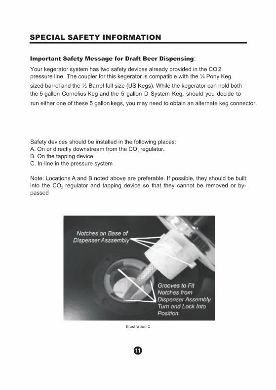
Important Safety Message for Draft Beer Dispensing
Safety devices should be installed in the following places:
A. On or directly downstream from the CO regulator.
B. On the tapping device
C. In-line in the pressure system
Note: Locations A and B noted above are preferable. If possible, they should be built
into the CO regulator and tapping device so that they cannot be removed or by-2
passed
Illustration C
11
SPECIAL SAFETY INFORMATION
:
Your kegerator system has two safety devices already provided in the CO 2
run either one of these 5 gallon kegs, you may need to obtain an alternate keg connector.
the 5 gallon Cornelius Keg and the 5 gallon D System Keg, should you decide to
sized barrel and the ½ Barrel full size (US Kegs). While the kegerator can hold both
pressure line. The coupler for this kegerator is compatible with the ¼ Pony Keg
2
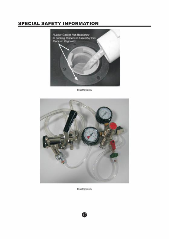
Illustration D
Illustration E
12
SPECIAL SAFETY INFORMATION

Illustration F
QUICK ASSEMBLY INSTRUCTIONS
Installing Casters
1. Remove all items from inside cabinet.
2. Lay kegerator on its side.
3. Install four casters, making sure the two locking casters are up front
4. Stand kegerator up on casters and allow Freon to settle for at least 8 hours
before plugging in.
*All O-rings and rubber washers are preinstalled by the factory, but should be double
checked. The bag of O-rings and rubber washers included are replacement pieces.
Installing Tower (Illustrations on page )
1. Remove cap from top of refrigerator.
2. Drop beer line connected to beer tower (6) through the opening in the
13
QUICK ASSEMBLY INSTRUCTIONS
6

refrigerator.
3. Sit tower down onto opening and turn counter clockwise to lock.
Install Guardrail
1. Place guardrail (10) over rubber inserts on refrigerator cabinet and push down to
secure.
Connecting regulator and coupler (Illustrations on page 9)
1. Make sure regulator valve and CO tank valve are off by turning clockwise.
2. Connect regulator (7) to CO tank (9). Use open wrench included to tighten.
3. Connect air hose (20) end with green nut to regulator (7).
4. Insert black CO rubber washer (4) in opening at back end of coupler (1) before
connecting air hose (20). Connect other end of air hose (20) to opening at back end
of coupler (1).
5. Insert back flow stopper (2), round end first, into top opening of coupler (1).
Insert rubber washer (3) into wing nut at end of beer line. Screw wing nut onto top
opening of coupler.
Installing Coupler
1. Make sure black handle on coupler (1) is in the UP position.
2. Insert coupler (1) into keg and turn clockwise to lock.
3. Pull and hold black handle on coupler (1) up and bring lever down to lock into
place.
Regulating Keg
1. Turn CO tank valve counter clockwise to open.
2. Turn blue regulator valve ¼ - ½ turn clockwise.
3. Within one minute, beer should begin to flow through the beer line.
* If beer is flowing too slowly, turn blue regulator valve counterclockwise until you
receive the desired flow.
** If too much foam dispenses, turn off all valves, pull pin on the side of the coupler
(1) to release the pressure. Wait 30 minutes and repeat steps 1-3 under 'regulating
keg.
14
QUICK ASSEMBLY INSTRUCTIONS
2
2
2
2

15
QUICK ASSEMBLY INSTRUCTIONS
Band
6

LIMITED MANUFACTURER'S WARRANTY
This appliance is covered by a limited manufacturer's warranty. For one year from
the original date of purchase, the manufacturer will repair or replace any parts of this
appliance that prove to be defective in materials and workmanship, provided the
appliance has been used under normal operating conditions as intended by the
manufacturer.
Warranty Terms:
During the first year, any components of this appliance found to be defective due to
materials or workmanship will be repaired or replaced, at the manufacturer's
discretion, at no charge to the original purchaser. The purchaser will be responsible
for any removal or transportation costs.
Warranty Exclusions:
The warranty will not apply if damage is caused by any of the following:
1. Power failure
2. Damage in transit or when moving the appliance
3. Improper power supply such as low voltage, defective household wiring or
inadequate fuses 4. Accident, alteration, misuse or abuse of the appliance such as using non-
5. Use in commercial or industrial applications
6. Fire, water damage, theft, war, riot, hostility or acts of God such as hurricanes,
floods, etc. 7. Use of force or damage caused by external influences
8. Partially or completely dismantled appliances
Obtaining Service:
When making a warranty claim, please have the original bill of purchase with
purchase date available. Once confirmed that your appliance is eligible for warranty
service, all repairs will be performed by a NewAir™ authorized repair facility. The
purchaser will be responsible for any removal or transportation costs. Replacement
parts and/or units will be new, re-manufactured or refurbished and is subject to the
manufacturer's discretion.
For technical support and warranty service, please email [email protected].
16
LIMITED MANUFACTURER'S WARRANTY
approved accessories, inadequate air circulation in the room or abnormal
operating conditions (extreme temperatures)