Embed Size (px)
Citation preview

Airworthinessof Aircraft
Annex 8to the Convention onInternational Civil Aviation
International Civil Aviation Organization
International Standards
and Recommended Practices
Tenth EditionApril 2005
This edition incorporates all amendmentsadopted by the Council prior to 14 December 2004and supersedes, on 13 December 2007, allprevious editions of Annex 8.
For information regarding the applicabilityof the Standards and Recommended Practices,see sections 1.1, 2.1, 3.1 and 4.1 of Part II, 1.1 of Parts IIIA and IVA, A.1 of Parts IIIB, IVB, V, VI and VII, and the Foreword.

Orders should be sent to one of the following addresses, together with the appropriate remittance (by bank draft, cheque or money order)in U.S. dollars or the currency of the country in which the order is placed. Credit card orders (American Express, MasterCard and Visa)are accepted at ICAO Headquarters.
International Civil Aviation Organization. Attention: Document Sales Unit, 999 University Street, Montréal, Quebec, Canada H3C 5H7Telephone: +1 (514) 954-8022; Facsimile: +1 (514) 954-6769; Sitatex: YULCAYA; E-mail: [email protected];World Wide Web: http://www.icao.int
China. Glory Master International Limited, Room 434B, Hongshen Trade Centre, 428 Dong Fang Road, Pudong, Shanghai 200120Telephone: +86 137 0177 4638; Facsimile: +86 21 5888 1629; E-mail: [email protected]
Egypt. ICAO Regional Director, Middle East Office, Egyptian Civil Aviation Complex, Cairo Airport Road, Heliopolis, Cairo 11776Telephone: +20 (2) 267 4840; Facsimile: +20 (2) 267 4843; Sitatex: CAICAYA; E-mail: [email protected]
France. Directeur régional de l’OACI, Bureau Europe et Atlantique Nord, 3 bis, villa Émile-Bergerat, 92522 Neuilly-sur-Seine (Cedex) Téléphone: +33 (1) 46 41 85 85; Fax: +33 (1) 46 41 85 00; Sitatex: PAREUYA; Courriel: [email protected]
Germany. UNO-Verlag GmbH, Am Hofgarten 10, D-53113 Bonn / Telephone: +49 (0) 2 28-9 49 0 20; Facsimile: +49 (0) 2 28-9 49 02 22;E-mail: [email protected]; World Wide Web: http://www.uno-verlag.de
India. Oxford Book and Stationery Co., Scindia House, New Delhi 110001 or 17 Park Street, Calcutta 700016Telephone: +91 (11) 331-5896; Facsimile: +91 (11) 51514284
India. Sterling Book House – SBH, 181, Dr. D. N. Road, Fort, Bombay 400001Telephone: +91 (22) 2261 2521, 2265 9599; Facsimile: +91 (22) 2262 3551; E-mail: [email protected]
Japan. Japan Civil Aviation Promotion Foundation, 15-12, 1-chome, Toranomon, Minato-Ku, TokyoTelephone: +81 (3) 3503-2686; Facsimile: +81 (3) 3503-2689
Kenya. ICAO Regional Director, Eastern and Southern African Office, United Nations Accommodation, P.O. Box 46294, Nairobi Telephone: +254 (20) 622 395; Facsimile: +254 (20) 623 028; Sitatex: NBOCAYA; E-mail: [email protected]
Mexico. Director Regional de la OACI, Oficina Norteamérica, Centroamérica y Caribe, Av. Presidente Masaryk No. 29, 3er Piso,Col. Chapultepec Morales, C.P. 11570, México D.F. / Teléfono: +52 (55) 52 50 32 11; Facsímile: +52 (55) 52 03 27 57; Correo-e: [email protected]
Nigeria. Landover Company, P.O. Box 3165, Ikeja, LagosTelephone: +234 (1) 4979780; Facsimile: +234 (1) 4979788; Sitatex: LOSLORK; E-mail: [email protected]
Peru. Director Regional de la OACI, Oficina Sudamérica, Apartado 4127, Lima 100Teléfono: +51 (1) 575 1646; Facsímile: +51 (1) 575 0974; Sitatex: LIMCAYA; Correo-e: [email protected]
Russian Federation. Aviaizdat, 48, Ivan Franko Street, Moscow 121351 / Telephone: +7 (095) 417-0405; Facsimile: +7 (095) 417-0254Senegal. Directeur régional de l’OACI, Bureau Afrique occidentale et centrale, Boîte postale 2356, Dakar
Téléphone: +221 839 9393; Fax: +221 823 6926; Sitatex: DKRCAYA; Courriel: [email protected]. Air Traffic Services of the Slovak Republic, Letové prevádzkové sluzby Slovenskej Republiky, State Enterprise,
Letisko M.R. Stefánika, 823 07 Bratislava 21 / Telephone: +421 (7) 4857 1111; Facsimile: +421 (7) 4857 2105South Africa. Avex Air Training (Pty) Ltd., Private Bag X102, Halfway House, 1685, Johannesburg
Telephone: +27 (11) 315-0003/4; Facsimile: +27 (11) 805-3649; E-mail: [email protected]. A.E.N.A. — Aeropuertos Españoles y Navegación Aérea, Calle Juan Ignacio Luca de Tena, 14, Planta Tercera, Despacho 3. 11,
28027 Madrid / Teléfono: +34 (91) 321-3148; Facsímile: +34 (91) 321-3157; Correo-e: [email protected]. Adeco-Editions van Diermen, Attn: Mr. Martin Richard Van Diermen, Chemin du Lacuez 41, CH-1807 Blonay
Telephone: +41 021 943 2673; Facsimile: +41 021 943 3605; E-mail: [email protected]. ICAO Regional Director, Asia and Pacific Office, P.O. Box 11, Samyaek Ladprao, Bangkok 10901
Telephone: +66 (2) 537 8189; Facsimile: +66 (2) 537 8199; Sitatex: BKKCAYA; E-mail: [email protected] Kingdom. Airplan Flight Equipment Ltd. (AFE), 1a Ringway Trading Estate, Shadowmoss Road, Manchester M22 5LH
Telephone: +44 161 499 0023; Facsimile: +44 161 499 0298; E-mail: [email protected]; World Wide Web: http://www.afeonline.com
Catalogue of ICAO Publicationsand Audio-visual Training Aids
Issued annually, the Catalogue lists all publications and audio-visual training aids currently available. Monthly supplements announce new publications and audio-visual training aids, amendments, supplements, reprints, etc.
Available free from the Document Sales Unit, ICAO.
2/05
Published in separate English, Arabic, Chinese, French, Russian and Spanish editions by the International Civil AviationOrganization. All correspondence, except orders and subscriptions, should be addressed to the Secretary General.

IMPORTANT NOTE
REGARDING ANNEX 8, NINTH AND TENTH EDITIONS
The Ninth Edition of Annex 8 contains International Standards and Recommended Practices thatwill be applicable on 20 May 2006. The Tenth Edition of Annex 8 contains International Standardsand Recommended Practices applicable only on 13 December 2007.
Users should therefore retain both the Ninth and Tenth Editions of Annex 8.
Airworthinessof Aircraft
Annex 8to the Convention onInternational Civil Aviation
International Civil Aviation Organization
International Standardsand Recommended Practices
Tenth EditionApril 2005
This edition incorporates all amendmentsadopted by the Council prior to 14 December 2004and supersedes, on 13 December 2007, allprevious editions of Annex 8.
For information regarding the applicabilityof the Standards and Recommended Practices,see sections 1.1, 2.1, 3.1 and 4.1 of Part II,1.1 of Parts IIIA and IVA, A.1 of Parts IIIB, IVB,V, VI and VII, and the Foreword.

AMENDMENTS
The issue of amendments is announced regularly in the ICAO Journal and in themonthly Supplement to the Catalogue of ICAO Publications and Audio-visualTraining Aids, which holders of this publication should consult. The space belowis provided to keep a record of such amendments.
RECORD OF AMENDMENTS AND CORRIGENDA
AMENDMENTS CORRIGENDA
No.Date
applicableDate
enteredEntered
by No.Date
of issueDate
enteredEntered
by
1-100 Incorporated in this edition
(ii)

ANNEX 8 (iii) 13/12/07
TABLE OF CONTENTS
Page Page
FOREWORD . . . . . . . . . . . . . . . . . . . . . . . . . . . . . . . (ix)
PART I. DEFINITIONS . . . . . . . . . . . . . . . . . . . . . I-1
PART II. PROCEDURES FOR CERTIFICATIONAND CONTINUING AIRWORTHINESS . . . . . . . . II-1-1
CHAPTER 1. Type certification. . . . . . . . . . . . . . . II-1-11.1 Applicability . . . . . . . . . . . . . . . . . . . . . . . . II-1-11.2 Design aspects of the appropriate
airworthiness requirements. . . . . . . . . . . . . II-1-11.3 Proof of compliance with the
appropriate airworthiness requirements . . . II-1-11.4 Type Certificate . . . . . . . . . . . . . . . . . . . . . II-1-2
CHAPTER 2. Production . . . . . . . . . . . . . . . . . . . . II-2-12.1 Applicability . . . . . . . . . . . . . . . . . . . . . . . . II-2-12.2 Production . . . . . . . . . . . . . . . . . . . . . . . . . . II-2-1
CHAPTER 3. Certificate of Airworthiness . . . . . . II-3-13.1 Applicability . . . . . . . . . . . . . . . . . . . . . . . . II-3-13.2 Issuance and continued validity of a
Certificate of Airworthiness . . . . . . . . . . . . II-3-13.3 Standard form of Certificate
of Airworthiness . . . . . . . . . . . . . . . . . . . . . II-3-13.4 Aircraft limitations and information . . . . . II-3-13.5 Temporary loss of airworthiness . . . . . . . . II-3-13.6 Damage to aircraft . . . . . . . . . . . . . . . . . . . II-3-2
CHAPTER 4. Continuing airworthiness of aircraft . . . . . . . . . . . . . . . . . . . . . . . . . . . . . . . . . . II-4-1
4.1 Applicability . . . . . . . . . . . . . . . . . . . . . . . . II-4-14.2 Responsibilities of Contracting States
in respect of continuing airworthiness . . . . II-4-1
PART III. LARGE AEROPLANES . . . . . . . . . . . . IIIA-1-1
PART IIIA. Aeroplanes over 5 700 kg for which application for certification was submitted on or after 13 June 1960, but before 2 March 2004 . . . . . IIIA-1-1
CHAPTER 1. General. . . . . . . . . . . . . . . . . . . . . . . IIIA-1-11.1 Applicability . . . . . . . . . . . . . . . . . . . . . . . . IIIA-1-11.2 Number of power-units. . . . . . . . . . . . . . . . IIIA-1-11.3 Operating limitations . . . . . . . . . . . . . . . . . IIIA-1-11.4 Unsafe features and characteristics . . . . . . IIIA-1-21.5 Proof of compliance . . . . . . . . . . . . . . . . . . IIIA-1-2
CHAPTER 2. Flight. . . . . . . . . . . . . . . . . . . . . . . . IIIA-2-12.1 General. . . . . . . . . . . . . . . . . . . . . . . . . . . . IIIA-2-12.2 Performance. . . . . . . . . . . . . . . . . . . . . . . . IIIA-2-12.3 Flying qualities . . . . . . . . . . . . . . . . . . . . . IIIA-2-2
CHAPTER 3. Structures . . . . . . . . . . . . . . . . . . . . IIIA-3-13.1 General. . . . . . . . . . . . . . . . . . . . . . . . . . . . IIIA-3-13.2 Airspeeds . . . . . . . . . . . . . . . . . . . . . . . . . . IIIA-3-13.3 Flight loads . . . . . . . . . . . . . . . . . . . . . . . . IIIA-3-13.4 Ground and water loads . . . . . . . . . . . . . . IIIA-3-23.5 Miscellaneous loads . . . . . . . . . . . . . . . . . IIIA-3-23.6 Flutter, divergence and vibration . . . . . . . IIIA-3-23.7 Fatigue strength . . . . . . . . . . . . . . . . . . . . . IIIA-3-2
CHAPTER 4. Design and construction. . . . . . . . . IIIA-4-14.1 General. . . . . . . . . . . . . . . . . . . . . . . . . . . . IIIA-4-1
CHAPTER 5. Engines . . . . . . . . . . . . . . . . . . . . . . IIIA-5-15.1 Scope . . . . . . . . . . . . . . . . . . . . . . . . . . . . . IIIA-5-15.2 Design, construction and functioning . . . . IIIA-5-15.3 Declared ratings, conditions and
limitations . . . . . . . . . . . . . . . . . . . . . . . . . IIIA-5-15.4 Tests . . . . . . . . . . . . . . . . . . . . . . . . . . . . . . IIIA-5-1
CHAPTER 6. Propellers . . . . . . . . . . . . . . . . . . . . IIIA-6-16.1 Scope . . . . . . . . . . . . . . . . . . . . . . . . . . . . . IIIA-6-16.2 Design, construction and functioning . . . . IIIA-6-16.3 Declared ratings, conditions and
limitations . . . . . . . . . . . . . . . . . . . . . . . . . IIIA-6-16.4 Tests . . . . . . . . . . . . . . . . . . . . . . . . . . . . . . IIIA-6-1
CHAPTER 7. Powerplant installation. . . . . . . . . . IIIA-7-17.1 General. . . . . . . . . . . . . . . . . . . . . . . . . . . . IIIA-7-17.2 Arrangement and functioning . . . . . . . . . . IIIA-7-1
CHAPTER 8. Instruments and equipment . . . . . . IIIA-8-18.1 Required instruments and equipment . . . . IIIA-8-18.2 Installation . . . . . . . . . . . . . . . . . . . . . . . . . IIIA-8-18.3 Safety and survival equipment . . . . . . . . . IIIA-8-18.4 Navigation lights and anti-collision
lights . . . . . . . . . . . . . . . . . . . . . . . . . . . . . IIIA-8-1
CHAPTER 9. Operating limitations and information . . . . . . . . . . . . . . . . . . . . . . . . . . . . . . . . IIIA-9-1
9.1 General. . . . . . . . . . . . . . . . . . . . . . . . . . . . IIIA-9-19.2 Operating limitations. . . . . . . . . . . . . . . . . IIIA-9-19.3 Operating information and procedures . . . IIIA-9-19.4 Performance information. . . . . . . . . . . . . . IIIA-9-29.5 Aeroplane flight manual . . . . . . . . . . . . . . IIIA-9-29.6 Markings and placards . . . . . . . . . . . . . . . IIIA-9-2

Annex 8 — Airworthiness of Aircraft Table of Contents
13/12/07 (iv)
Page Page
CHAPTER 10. Continuing airworthiness — maintenance information . . . . . . . . . . . . . . . . . . . . . . IIIA-10-1
10.1 General . . . . . . . . . . . . . . . . . . . . . . . . . . . . IIIA-10-110.2 Maintenance information . . . . . . . . . . . . . . IIIA-10-110.3 Maintenance programme information . . . . IIIA-10-110.4 Maintenance information resulting
from the type design approval . . . . . . . . . . IIIA-10-1
CHAPTER 11. Security . . . . . . . . . . . . . . . . . . . . . IIIA-11-111.1 Aeroplanes used for domestic
commercial operations . . . . . . . . . . . . . . . . IIIA-11-111.2 Least-risk bomb location . . . . . . . . . . . . . . IIIA-11-111.3 Protection of the flight crew
compartment . . . . . . . . . . . . . . . . . . . . . . . . IIIA-11-111.4 Interior design. . . . . . . . . . . . . . . . . . . . . . . IIIA-11-1
PART IIIB. Aeroplanes over 5 700 kg for whichapplication for certification was submitted on orafter 2 March 2004 . . . . . . . . . . . . . . . . . . . . . . . . . . IIIB-A-1
SUB-PART A. General . . . . . . . . . . . . . . . . . . . . . . IIIB-A-1A.1 Applicability . . . . . . . . . . . . . . . . . . . . . . . . IIIB-A-1A.2 Operating limitations . . . . . . . . . . . . . . . . . IIIB-A-1A.3 Unsafe features and characteristics . . . . . . IIIB-A-1A.4 Proof of compliance . . . . . . . . . . . . . . . . . . IIIB-A-1
SUB-PART B. Flight . . . . . . . . . . . . . . . . . . . . . . . IIIB-B-1B.1 General . . . . . . . . . . . . . . . . . . . . . . . . . . . . IIIB-B-1B.2 Performance design parameters . . . . . . . . . IIIB-B-1B.3 Flying qualities . . . . . . . . . . . . . . . . . . . . . . IIIB-B-2B.4 Stability and control . . . . . . . . . . . . . . . . . . IIIB-B-3
SUB-PART C. Structure . . . . . . . . . . . . . . . . . . . . . IIIB-C-1C.1 General . . . . . . . . . . . . . . . . . . . . . . . . . . . . IIIB-C-1C.2 Mass and mass distribution . . . . . . . . . . . . IIIB-C-1C.3 Limit loads . . . . . . . . . . . . . . . . . . . . . . . . . IIIB-C-1C.4 Deformation and ultimate strength . . . . . . IIIB-C-1C.5 Airspeeds. . . . . . . . . . . . . . . . . . . . . . . . . . . IIIB-C-1C.6 Strength . . . . . . . . . . . . . . . . . . . . . . . . . . . . IIIB-C-1C.7 Survivability . . . . . . . . . . . . . . . . . . . . . . . . IIIB-C-2C.8 Structural durability . . . . . . . . . . . . . . . . . . IIIB-C-2
SUB-PART D. Design and construction . . . . . . . . IIIB-D-1D.1 General . . . . . . . . . . . . . . . . . . . . . . . . . . . . IIIB-D-1D.2 Systems design features . . . . . . . . . . . . . . . IIIB-D-1D.3 Aeroelasticity . . . . . . . . . . . . . . . . . . . . . . . IIIB-D-2D.4 Occupants accommodation features. . . . . . IIIB-D-3D.5 Electrical bonding and protection against
lightning and static electricity . . . . . . . . . . IIIB-D-3D.6 Emergency landing provisions . . . . . . . . . . IIIB-D-3D.7 Ground handling . . . . . . . . . . . . . . . . . . . . . IIIB-D-3
SUB-PART E. Powerplant . . . . . . . . . . . . . . . . . . . IIIB-E-1E.1 Engines . . . . . . . . . . . . . . . . . . . . . . . . . . . . IIIB-E-1E.2 Propellers . . . . . . . . . . . . . . . . . . . . . . . . . . IIIB-E-1E.3 Powerplant installation . . . . . . . . . . . . . . . . IIIB-E-1
SUB-PART F. Systems and equipment . . . . . . . . . IIIB-F-1F.1 General. . . . . . . . . . . . . . . . . . . . . . . . . . . . IIIB-F-1F.2 Installation . . . . . . . . . . . . . . . . . . . . . . . . . IIIB-F-1F.3 Safety and survival equipment . . . . . . . . . IIIB-F-1F.4 Navigation lights and anti-collision
lights . . . . . . . . . . . . . . . . . . . . . . . . . . . . . IIIB-F-1F.5 Electromagnetic interference protection . . IIIB-F-2F.6 Ice protection . . . . . . . . . . . . . . . . . . . . . . . IIIB-F-2
SUB-PART G. Operating limitations and information . . . . . . . . . . . . . . . . . . . . . . . . . . . . . . . . IIIB-G-1
G.1 General. . . . . . . . . . . . . . . . . . . . . . . . . . . . IIIB-G-1G.2 Operating limitations. . . . . . . . . . . . . . . . . IIIB-G-1G.3 Operating information and procedures . . . IIIB-G-1G.4 Performance information. . . . . . . . . . . . . . IIIB-G-2G.5 Flight manual. . . . . . . . . . . . . . . . . . . . . . . IIIB-G-2G.6 Markings and placards . . . . . . . . . . . . . . . IIIB-G-2G.7 Continuing airworthiness —
maintenance information . . . . . . . . . . . . . . IIIB-G-2
SUB-PART H. Systems software . . . . . . . . . . . . . IIIB-H-1
SUB-PART I. Crashworthiness and cabin safety . . . . . . . . . . . . . . . . . . . . . . . . . . . . . . . . IIIB-I-1
I.1 General. . . . . . . . . . . . . . . . . . . . . . . . . . . . IIIB-I-1I.2 Design emergency landing loads . . . . . . . IIIB-I-1I.3 Cabin fire protection . . . . . . . . . . . . . . . . . IIIB-I-1I.4 Evacuation . . . . . . . . . . . . . . . . . . . . . . . . . IIIB-I-1I.5 Lighting and marking . . . . . . . . . . . . . . . . IIIB-I-1I.6 Survival equipment . . . . . . . . . . . . . . . . . . IIIB-I-1
SUB-PART J. Operating environment and Human Factors . . . . . . . . . . . . . . . . . . . . . . . . . . . . . IIIB-J-1
J.1 General. . . . . . . . . . . . . . . . . . . . . . . . . . . . IIIB-J-1J.2 Flight crew. . . . . . . . . . . . . . . . . . . . . . . . . IIIB-J-1J.3 Ergonomics . . . . . . . . . . . . . . . . . . . . . . . . IIIB-J-1J.4 Operating environmental factors. . . . . . . . IIIB-J-1
SUB-PART K. Security . . . . . . . . . . . . . . . . . . . . . IIIB-K-1K.1 Aeroplanes used for domestic
commercial operations . . . . . . . . . . . . . . . IIIB-K-1K.2 Least-risk bomb location. . . . . . . . . . . . . . IIIB-K-1K.3 Protection of the flight crew
compartment . . . . . . . . . . . . . . . . . . . . . . . IIIB-K-1K.4 Interior design . . . . . . . . . . . . . . . . . . . . . . IIIB-K-1
PART IV. HELICOPTERS . . . . . . . . . . . . . . . . . . IVA-1-1
PART IVA. Helicopters for which application for certification was submitted on or after22 March 1991 but before 13 December 2007 . . . . IVA-1-1
CHAPTER 1. General . . . . . . . . . . . . . . . . . . . . . . IVA-1-11.1 Applicability . . . . . . . . . . . . . . . . . . . . . . . IVA-1-1
Table of Contents Annex 8 — Airworthiness of Aircraft
(v) 13/12/07
Page Page
1.2 Limitations . . . . . . . . . . . . . . . . . . . . . . . . . IVA-1-11.3 Unsafe features and characteristics . . . . . . IVA-1-11.4 Proof of compliance . . . . . . . . . . . . . . . . . . IVA-1-2
CHAPTER 2. Flight . . . . . . . . . . . . . . . . . . . . . . . . IVA-2-12.1 General . . . . . . . . . . . . . . . . . . . . . . . . . . . . IVA-2-12.2 Performance . . . . . . . . . . . . . . . . . . . . . . . . IVA-2-12.3 Flying qualities . . . . . . . . . . . . . . . . . . . . . . IVA-2-2
CHAPTER 3. Structures . . . . . . . . . . . . . . . . . . . . . IVA-3-13.1 General . . . . . . . . . . . . . . . . . . . . . . . . . . . . IVA-3-13.2 Airspeeds. . . . . . . . . . . . . . . . . . . . . . . . . . . IVA-3-13.3 Main rotor(s) rotational speed limits . . . . . IVA-3-13.4 Flight loads . . . . . . . . . . . . . . . . . . . . . . . . . IVA-3-13.5 Ground and water loads . . . . . . . . . . . . . . . IVA-3-13.6 Miscellaneous loads . . . . . . . . . . . . . . . . . . IVA-3-23.7 Flutter, divergence and vibration . . . . . . . . IVA-3-23.8 Fatigue strength . . . . . . . . . . . . . . . . . . . . . IVA-3-2
CHAPTER 4. Design and construction . . . . . . . . . IVA-4-14.1 General . . . . . . . . . . . . . . . . . . . . . . . . . . . . IVA-4-1
CHAPTER 5. Engines. . . . . . . . . . . . . . . . . . . . . . . IVA-5-15.1 Scope. . . . . . . . . . . . . . . . . . . . . . . . . . . . . . IVA-5-15.2 Design, construction and functioning . . . . IVA-5-15.3 Declared ratings, conditions and
limitations . . . . . . . . . . . . . . . . . . . . . . . . . . IVA-5-15.4 Tests . . . . . . . . . . . . . . . . . . . . . . . . . . . . . . IVA-5-1
CHAPTER 6. Rotor and power transmission systems and powerplant installation . . . . . . . . . . . . . IVA-6-1
6.1 General . . . . . . . . . . . . . . . . . . . . . . . . . . . . IVA-6-16.2 Design, construction and functioning . . . . IVA-6-16.3 Declared ratings, conditions and
limitations . . . . . . . . . . . . . . . . . . . . . . . . . . IVA-6-16.4 Tests . . . . . . . . . . . . . . . . . . . . . . . . . . . . . . IVA-6-16.5 Compliance with engine and rotor
and power transmission systems limitations . . . . . . . . . . . . . . . . . . . . . . . . . . IVA-6-1
6.6 Control of engine rotation . . . . . . . . . . . . . IVA-6-16.7 Engine restarting. . . . . . . . . . . . . . . . . . . . . IVA-6-16.8 Arrangement and functioning. . . . . . . . . . . IVA-6-2
CHAPTER 7. Instruments and equipment . . . . . . . IVA-7-17.1 Required instruments and equipment. . . . . IVA-7-17.2 Installation. . . . . . . . . . . . . . . . . . . . . . . . . . IVA-7-17.3 Safety and survival equipment . . . . . . . . . . IVA-7-17.4 Navigation lights and anti-collision
lights . . . . . . . . . . . . . . . . . . . . . . . . . . . . . . IVA-7-1
CHAPTER 8. Electrical systems . . . . . . . . . . . . . . IVA-8-1
CHAPTER 9. Operating limitations and information. . . . . . . . . . . . . . . . . . . . . . . . . . . . . . . . . IVA-9-1
9.1 General . . . . . . . . . . . . . . . . . . . . . . . . . . . . IVA-9-19.2 Operating limitations . . . . . . . . . . . . . . . . . IVA-9-19.3 Operating information and procedures . . . IVA-9-1
9.4 Performance information. . . . . . . . . . . . . . IVA-9-29.5 Helicopter flight manual . . . . . . . . . . . . . . IVA-9-29.6 Markings and placards . . . . . . . . . . . . . . . IVA-9-2
PART IVB. Helicopters for which application for certification was submitted on or after13 December 2007 . . . . . . . . . . . . . . . . . . . . . . . . . . IVB-A-1
SUB-PART A. General . . . . . . . . . . . . . . . . . . . . . IVB-A-1A.1 Applicability . . . . . . . . . . . . . . . . . . . . . . . IVB-A-1A.2 Operating limitations. . . . . . . . . . . . . . . . . IVB-A-1A.3 Unsafe features and characteristics. . . . . . IVB-A-1A.4 Proof of compliance . . . . . . . . . . . . . . . . . IVB-A-1
SUB-PART B. Flight . . . . . . . . . . . . . . . . . . . . . . . IVB-B-1B.1 General. . . . . . . . . . . . . . . . . . . . . . . . . . . . IVB-B-1B.2 Performance. . . . . . . . . . . . . . . . . . . . . . . . IVB-B-1B.3 Flying qualities . . . . . . . . . . . . . . . . . . . . . IVB-B-2B.4 Stability and control . . . . . . . . . . . . . . . . . IVB-B-3
SUB-PART C. Structure . . . . . . . . . . . . . . . . . . . . IVB-C-1C.1 General. . . . . . . . . . . . . . . . . . . . . . . . . . . . IVB-C-1C.2 Mass and mass distribution. . . . . . . . . . . . IVB-C-1C.3 Limit loads. . . . . . . . . . . . . . . . . . . . . . . . . IVB-C-1C.4 Strength and deformation . . . . . . . . . . . . . IVB-C-1C.5 Airspeeds . . . . . . . . . . . . . . . . . . . . . . . . . . IVB-C-1C.6 Main rotor(s) rotational speed limits . . . . IVB-C-1C.7 Loads . . . . . . . . . . . . . . . . . . . . . . . . . . . . . IVB-C-1C.8 Ground and water loads . . . . . . . . . . . . . . IVB-C-2C.9 Miscellaneous loads . . . . . . . . . . . . . . . . . IVB-C-2C.10 Fatigue strength . . . . . . . . . . . . . . . . . . . . . IVB-C-2C.11 Special factors . . . . . . . . . . . . . . . . . . . . . . IVB-C-2
SUB-PART D. Design and construction . . . . . . . . IVB-D-1D.1 General. . . . . . . . . . . . . . . . . . . . . . . . . . . . IVB-D-1D.2 Systems design features . . . . . . . . . . . . . . IVB-D-1D.3 Flutter. . . . . . . . . . . . . . . . . . . . . . . . . . . . . IVB-D-2D.4 Occupant accommodation features . . . . . . IVB-D-2D.5 Electrical bonding and protection
against lightning and static electricity . . . IVB-D-2D.6 Emergency landing provisions . . . . . . . . . IVB-D-2D.7 Ground handling . . . . . . . . . . . . . . . . . . . . IVB-D-2
SUB-PART E. Rotors and powerplant . . . . . . . . . IVB-E-1E.1 Engines . . . . . . . . . . . . . . . . . . . . . . . . . . . IVB-E-1E.2 Rotors and powerplant installation . . . . . . IVB-E-1
SUB-PART F. Systems and equipment . . . . . . . . . IVB-F-1F.1 General. . . . . . . . . . . . . . . . . . . . . . . . . . . . IVB-F-1F.2 Installation . . . . . . . . . . . . . . . . . . . . . . . . . IVB-F-1F.3 Safety and survival equipment . . . . . . . . . IVB-F-1F.4 Navigation lights and anti-collision
lights . . . . . . . . . . . . . . . . . . . . . . . . . . . . . IVB-F-1F.5 Electromagnetic interference protection . . IVB-F-1F.6 Ice protection . . . . . . . . . . . . . . . . . . . . . . . IVB-F-2
Annex 8 — Airworthiness of Aircraft Table of Contents
13/12/07 (vi)
Page Page
SUB-PART G. Operating limitations and information. . . . . . . . . . . . . . . . . . . . . . . . . . . . . . . . . IVB-G-1
G.1 General . . . . . . . . . . . . . . . . . . . . . . . . . . . . IVB-G-1G.2 Operating limitations . . . . . . . . . . . . . . . . . IVB-G-1G.3 Operating information and procedures . . . IVB-G-1G.4 Performance information . . . . . . . . . . . . . . IVB-G-2G.5 Flight manual . . . . . . . . . . . . . . . . . . . . . . . IVB-G-2G.6 Markings and placards . . . . . . . . . . . . . . . . IVB-G-2G.7 Continuing airworthiness —
maintenance information . . . . . . . . . . . . . . IVB-G-2
SUB-PART H. Systems software . . . . . . . . . . . . . . IVB-H-1
SUB-PART I. Crashworthiness and cabin safety . . . . . . . . . . . . . . . . . . . . . . . . . . . . . . . . IVB-I-1
I.1 General . . . . . . . . . . . . . . . . . . . . . . . . . . . . IVB-I-1I.2 Design emergency landing conditions . . . . IVB-I-1I.3 Cabin fire protection. . . . . . . . . . . . . . . . . . IVB-I-1I.4 Evacuation. . . . . . . . . . . . . . . . . . . . . . . . . . IVB-I-1I.5 Lighting and marking . . . . . . . . . . . . . . . . . IVB-I-1
SUB-PART J. Operating environment and Human Factors . . . . . . . . . . . . . . . . . . . . . . . . . . . . . . IVB-J-1
J.1 General . . . . . . . . . . . . . . . . . . . . . . . . . . . . IVB-J-1J.2 Flight crew . . . . . . . . . . . . . . . . . . . . . . . . . IVB-J-1J.3 Ergonomics . . . . . . . . . . . . . . . . . . . . . . . . . IVB-J-1J.4 Operating environmental factors . . . . . . . . IVB-J-1
PART V. SMALL AEROPLANES — AEROPLANESOVER 750 KG BUT NOT EXCEEDING 5 700 KG FOR WHICH APPLICATION FOR CERTIFICATION WAS SUBMITTED ON OR AFTER13 DECEMBER 2007) . . . . . . . . . . . . . . . . . . . . . . . V-A-1
SUB-PART A. General . . . . . . . . . . . . . . . . . . . . . . V-A-1A.1 Applicability . . . . . . . . . . . . . . . . . . . . . . . . V-A-1A.2 Operating limitations . . . . . . . . . . . . . . . . . V-A-1A.3 Unsafe features and characteristics . . . . . . V-A-1A.4 Proof of compliance . . . . . . . . . . . . . . . . . . V-A-1
SUB-PART B. Flight . . . . . . . . . . . . . . . . . . . . . . . V-B-1B.1 General . . . . . . . . . . . . . . . . . . . . . . . . . . . . V-B-1B.2 Performance . . . . . . . . . . . . . . . . . . . . . . . . V-B-1B.3 Flying qualities . . . . . . . . . . . . . . . . . . . . . . V-B-2B.4 Stability and control . . . . . . . . . . . . . . . . . . V-B-3
SUB-PART C. Structure . . . . . . . . . . . . . . . . . . . . . V-C-1C.1 General . . . . . . . . . . . . . . . . . . . . . . . . . . . . V-C-1C.2 Mass and mass distribution . . . . . . . . . . . . V-C-1C.3 Limit loads . . . . . . . . . . . . . . . . . . . . . . . . . V-C-1C.4 Deformation and ultimate strength . . . . . . V-C-1C.5 Airspeeds. . . . . . . . . . . . . . . . . . . . . . . . . . . V-C-1C.6 Strength . . . . . . . . . . . . . . . . . . . . . . . . . . . . V-C-1C.7 Survivability . . . . . . . . . . . . . . . . . . . . . . . . V-C-2C.8 Structural durability . . . . . . . . . . . . . . . . . . V-C-2
SUB-PART D. Design and construction . . . . . . . . V-D-1D.1 General. . . . . . . . . . . . . . . . . . . . . . . . . . . . V-D-1D.2 Systems design features . . . . . . . . . . . . . . V-D-1D.3 Aeroelasticity. . . . . . . . . . . . . . . . . . . . . . . V-D-2D.4 Occupant accommodation features . . . . . . V-D-2D.5 Electrical bonding and protection against
lightning and static electricity. . . . . . . . . . V-D-2D.6 Emergency landing provisions . . . . . . . . . V-D-2D.7 Ground handling . . . . . . . . . . . . . . . . . . . . V-D-2
SUB-PART E. Powerplant. . . . . . . . . . . . . . . . . . . V-E-1E.1 Engines . . . . . . . . . . . . . . . . . . . . . . . . . . . V-E-1E.2 Propellers . . . . . . . . . . . . . . . . . . . . . . . . . . V-E-1E.3 Powerplant installation . . . . . . . . . . . . . . . V-E-1
SUB-PART F. Systems and equipment . . . . . . . . . V-F-1F.1 General. . . . . . . . . . . . . . . . . . . . . . . . . . . . V-F-1F.2 Installation . . . . . . . . . . . . . . . . . . . . . . . . . V-F-1F.3 Safety and survival equipment . . . . . . . . . V-F-1F.4 Navigation lights and anti-collision
lights . . . . . . . . . . . . . . . . . . . . . . . . . . . . . V-F-1F.5 Electromagnetic interference protection . . V-F-1F.6 Ice protection . . . . . . . . . . . . . . . . . . . . . . . V-F-1
SUB-PART G. Operating limitations and information . . . . . . . . . . . . . . . . . . . . . . . . . . . . . . . . V-G-1
G.1 General. . . . . . . . . . . . . . . . . . . . . . . . . . . . V-G-1G.2 Operating limitations. . . . . . . . . . . . . . . . . V-G-1G.3 Operating information and procedures . . . V-G-1G.4 Performance information. . . . . . . . . . . . . . V-G-2G.5 Flight manual. . . . . . . . . . . . . . . . . . . . . . . V-G-2G.6 Markings and placards . . . . . . . . . . . . . . . V-G-2G.7 Continuing airworthiness —
maintenance information . . . . . . . . . . . . . . V-G-2
SUB-PART H. Systems software . . . . . . . . . . . . . V-H-1
SUB-PART I. Crashworthiness and cabin safety . . . . . . . . . . . . . . . . . . . . . . . . . . . . . . . . V-I-1
I.1 General. . . . . . . . . . . . . . . . . . . . . . . . . . . . V-I-1I.2 Design emergency landing loads . . . . . . . V-I-1I.3 Cabin fire protection . . . . . . . . . . . . . . . . . V-I-1I.4 Evacuation . . . . . . . . . . . . . . . . . . . . . . . . . V-I-1I.5 Lighting and marking . . . . . . . . . . . . . . . . V-I-1
SUB-PART J. Operating environment and Human Factors . . . . . . . . . . . . . . . . . . . . . . . . . . . . . V-J-1
J.1 General. . . . . . . . . . . . . . . . . . . . . . . . . . . . V-J-1J.2 Flight crew. . . . . . . . . . . . . . . . . . . . . . . . . V-J-1J.3 Ergonomics . . . . . . . . . . . . . . . . . . . . . . . . V-J-1J.4 Operating environmental factors. . . . . . . . V-J-1
PART VI. ENGINES . . . . . . . . . . . . . . . . . . . . . . . VI-A-1
SUB-PART A. General . . . . . . . . . . . . . . . . . . . . . VI-A-1A.1 Applicability . . . . . . . . . . . . . . . . . . . . . . . VI-A-1

Table of Contents Annex 8 — Airworthiness of Aircraft
(vii) 13/12/07
Page Page
A.2 Engine installation and interfaces . . . . . . . VI-A-1A.3 Declared ratings, conditions and limitations VI-A-1A.4 Continuing airworthiness —
maintenance information . . . . . . . . . . . . . . VI-A-1
SUB-PART B. Design and construction. . . . . . . . . VI-B-1B.1 Functioning . . . . . . . . . . . . . . . . . . . . . . . . . VI-B-1B.2 Failure analysis . . . . . . . . . . . . . . . . . . . . . . VI-B-1B.3 Materials and manufacturing methods . . . . VI-B-1B.4 Integrity. . . . . . . . . . . . . . . . . . . . . . . . . . . . VI-B-1
SUB-PART C. Tests . . . . . . . . . . . . . . . . . . . . . . . . VI-C-1
PART VII. PROPELLERS . . . . . . . . . . . . . . . . . . . VII-A-1
SUB-PART A. General . . . . . . . . . . . . . . . . . . . . . VII-A-1A.1 Applicability . . . . . . . . . . . . . . . . . . . . . . . VII-A-1A.2 Declared ratings, conditions and limitations VII-A-1A.3 Continuing airworthiness —
maintenance information . . . . . . . . . . . . . . VII-A-1
SUB-PART B. Design and construction . . . . . . . . VII-B-1B.1 Functioning . . . . . . . . . . . . . . . . . . . . . . . . VII-B-1B.2 Failure analysis . . . . . . . . . . . . . . . . . . . . . VII-B-1B.3 Materials and manufacturing methods . . . VII-B-1B.4 Pitch control and indication . . . . . . . . . . . VII-B-1
SUB-PART C. Tests and inspection . . . . . . . . . . . VII-C-1C.1 Blade retention test . . . . . . . . . . . . . . . . . . VII-C-1C.2 Operational and endurance tests . . . . . . . . VII-C-1

ANNEX 8 (ix) 13/12/07
FOREWORD
Historical background
Standards and Recommended Practices for the Airworthinessof Aircraft were adopted by the Council on 1 March 1949pursuant to the provisions of Article 37 of the Convention onInternational Civil Aviation (Chicago 1944) and designated asAnnex 8 to the Convention.
The Annex contained, in Part II, general airworthinessprocedures applicable to all aircraft and in Part III, minimumairworthiness characteristics for aeroplanes provided, or to beprovided, with certificates of airworthiness classifying them inan established ICAO category. Part I contained definitions.
At its fourth session, the Airworthiness Division collabor-ating with the Operations Division made recommendationsconcerning the use of a performance code as an alternative tothe one contained in the Annex, in which the climb values hadthe status of Recommended Practices. Further, the Airworthi-ness Division made recommendations concerning certainaspects of the certification in ICAO categories. As a result ofthose recommendations, the Council approved the incorpor-ation of the alternative performance code as Attachment A butstated its belief that since agreement had not yet been reachedon Standards covering performance, there existed no basis forcertification in ICAO Category A. It urged the ContractingStates to refrain from such certification pending the becomingeffective of Standards on performance or until such time as theCouncil decides on the basic policy on airworthiness.
The Assembly at its seventh session (June 1953)endorsed the action already taken by the Council and the AirNavigation Commission to initiate a fundamental study ofICAO policy on international airworthiness and directed theCouncil to complete the study as rapidly as practicable.
In pursuing such study, the Air Navigation Commissionwas helped by an international body of experts designatedas the “Airworthiness Panel”, which contributed to the prep-aration of the work of the Third Air Navigation Conference.
As a result of these studies, a revised policy on interna-tional airworthiness was developed and it was approvedby the Council in 1956. According to this policy, the principleof certification in an ICAO Category was abandoned. Instead,Annex 8 included broad Standards which defined, for applica-tion by the competent national authorities, the complete mini-mum international basis for the recognition by States ofcertificates of airworthiness for the purpose of the flight ofaircraft of other States into or over their territories, therebyachieving, among other purposes, protection of other aircraft,
third persons and property. It was considered that this met theobligation of the Organization under Article 37 of the Conven-tion to adopt International Standards of airworthiness.
It was recognized that the ICAO Standards of airworthinesswould not replace national regulations and that national codesof airworthiness containing the full scope and extent of detailconsidered necessary by individual States would be necessaryas the basis for the certification of individual aircraft. EachState would establish its own comprehensive and detailed codeof airworthiness or would select a comprehensive and detailedcode established by another Contracting State. The level ofairworthiness defined by this code would be indicated by theStandards, supplemented, if necessary, by Acceptable Meansof Compliance.
In application of those principles, the Annex was declaredas constituting the minimum standards for the purpose ofArticle 33. It was also recognized that the Annex might, at thetime of adoption, not include technical Standards for allclasses of aircraft or even for all classes of aeroplanes, if theCouncil felt that no technical Standards were required at thattime to render Article 33 operative. Furthermore, adoption oramendment of the Annex declared to be complete for thepurpose of Article 33 did not constitute the end of ICAO’swork in the airworthiness field, as there was a need to continueinternational collaboration in airworthiness matters.
A revised text for Annex 8 consistent with the aboveprinciples was prepared on the basis of the recommendationsmade by the Third Air Navigation Conference (Montréal,September–October 1956). Part III of the Annex was limitedto broad Standards stating the objectives rather than themethods of realizing those objectives. However, to indicate byexamples the level of airworthiness intended by some of thebroad Standards, specifications of a more detailed and quanti-tative nature were included under the title “Acceptable Meansof Compliance”. These specifications were intended to assistthe Contracting States in the establishment and application ofcomprehensive and detailed national airworthiness codes.
To adopt a code giving an appreciably lower level ofairworthiness than that given in an Acceptable Means ofCompliance was considered to be a violation of the Standardsupplemented by that Acceptable Means of Compliance.
The revised text for Annex 8 was included in the FourthEdition of the Annex, which superseded the First, Second andThird Editions.
Another recommendation of the Third Air NavigationConference led to the establishment by the Council in 1957 of
Annex 8 — Airworthiness of Aircraft Foreword
13/12/07 (x)
the Airworthiness Committee, consisting of airworthinessexperts with broad experience and selected from thoseContracting States and International Organizations willing tocontribute.
Present policy on international airworthiness. There hadbeen some concern about the slow progress that had beenmade over the years with respect to developing supplementaryairworthiness specifications in the form of Acceptable Meansof Compliance. It was noted that the majority of the Accept-able Means of Compliance in Annexes 6 and 8 had beendeveloped in 1957 and were therefore applicable to only thoseaeroplane types operating at that time. No effort had beenmade to update the specifications in these Acceptable Meansof Compliance nor had there been any recommendations fromthe Airworthiness Committee for upgrading of any of theProvisional Acceptable Means of Compliance, which had beendeveloped as potential material for full-fledged AcceptableMeans of Compliance. The Air Navigation Commissiontherefore requested the Airworthiness Committee to review theprogress made by it since its inception with a view to deter-mining whether or not desired results had been achieved andto recommend any changes to improve the development ofdetailed airworthiness specifications.
The Airworthiness Committee at its Ninth Meeting(Montréal, November/December 1970) made a detailed studyof the problems and recommended that the concept ofdeveloping airworthiness specifications in the form of Accept-able Means of Compliance and Provisional Acceptable Meansof Compliance be abandoned and a provision be made for anairworthiness technical manual to be prepared and publishedby ICAO to include guidance material intended to facilitate thedevelopment and uniformity of national airworthiness codesby Contracting States.
The Air Navigation Commission reviewed the recommen-dations of the Airworthiness Committee in the light of thehistory of the development of the airworthiness policyapproved by the Council in 1956. It came to the conclusionthat the basic objectives and principles on which the ICAOairworthiness policy had been based were sound and did notrequire any significant change. It was also concluded that themain reason for the slow progress in the development ofairworthiness specifications in the form of Acceptable Meansof Compliance and Provisional Acceptable Means of Com-pliance was the degree of mandatory status to the formerimplied by the following statement included in the Forewordsof the Fourth and Fifth Editions of Annex 8:
“To adopt a code giving an appreciably lowerlevel of airworthiness than that given in anAcceptable Means of Compliance would be aviolation of the Standard supplemented by thatAcceptable Means of Compliance.”
Several approaches were examined by the Air NavigationCommission to eliminate this difficulty. Finally, it came to theconclusion that the idea of developing airworthiness specifi-cations in the form of Acceptable Means of Compliance and
Provisional Acceptable Means of Compliance should be aban-doned and ICAO should declare that the States’ obligations,for the purpose of Article 33 of the Convention, shall be metby their compliance with the broad Standards in Annex 8supplemented, as necessary, by airworthiness technical guid-ance material, devoid of all mandatory implications or obliga-tions. Also the requirement that each Contracting State shouldeither establish its own comprehensive and detailed code ofairworthiness or select a comprehensive and detailed codeestablished by another Contracting State should be retained.
The Council on 15 March 1972 approved the aboveapproach to form the basis for the present policy of ICAOin the field of airworthiness. According to this policy:
a) the objective of international airworthiness Standards isto define, for application by the competent nationalauthorities, the minimum level of airworthiness consti-tuting the international basis for the recognition byStates, under Article 33 of the Convention, of certifi-cates of airworthiness for the purpose of the flight ofaircraft of other States into or over their territories,thereby achieving, among other things, protection ofother aircraft, third parties and property;
b) the Standards developed to meet the objective stated ina) are considered by the Council as meeting, in thenecessary scope and detail, the obligations of the Organ-ization under Article 37 of the Convention to adoptInternational Standards of airworthiness;
c) international airworthiness Standards adopted by theCouncil are recognized as being the completeinternational code necessary to bring into force andeffect the rights and obligations which arise underArticle 33 of the Convention;
d) the technical airworthiness Standards in Annex 8 shallbe presented as broad specifications stating theobjectives rather than the means of realizing theseobjectives; ICAO recognizes that national codes ofairworthiness containing the full scope and extent ofdetail considered necessary by individual States arerequired as the basis for the certification by individualStates of airworthiness of each aircraft;
e) to assist States in applying the Standards of Annex 8and in developing their own comprehensive nationalcodes in a uniform manner, detailed guidance materialshall be developed and published expeditiously in theworking languages of the Organization.
The Council also approved the issuance of the airworthinessguidance material under the title of Airworthiness TechnicalManual. It was understood that the guidance material will,before issuance, be examined by the Air NavigationCommission. It will however have no formal status and itsmain purpose would be to provide guidance to ContractingStates in developing the appropriate airworthiness requirementsmentioned in 3.2.2 of Part II of the Annex.

Foreword Annex 8 — Airworthiness of Aircraft
(xi) 13/12/07
A text for Annex 8 consistent with the policy oninternational airworthiness, approved by the Council on15 March 1972, was developed by the Air NavigationCommission.
Table A shows the origin of amendments together with alist of the principal subjects involved and the dates on whichthe Annex and the amendments were adopted by the Council,when they became effective and when they became applicable.
On 6 June 2000, the Air Navigation Commission reviewedthe recommendation of the Continuing Airworthiness Paneland the Airworthiness Study Group, in light of the introductionof the type certification process, to introduce the Type Certifi-cate concept. It came to the conclusion that this internationallyused and known certificate was already introduced in the Air-worthiness Technical Manual (Doc 9051) and that its introduc-tion complements the type certification process, making thetext of Annex 8 consistent with its international airworthinessuse.
It was further noted that the State of Registry, which is incharge of the issuance or validation of Certificates ofAirworthiness by virtue of Article 31 of the Convention, andthe State of Design may be different States, with separatefunctions and duties, and two independent responsibilities.Accordingly, the requirements governing the issuance of TypeCertificates in accordance with applicable provisions ofAnnex 8 are not part of “the minimum standards” whichgovern the issuance or validation of Certificates of Airworthi-ness, and lead to the recognition of their validity pursuant toArticle 33 of the Convention.
On 7 October 2003, the Air Navigation Commissionreviewed the recommendations of the Airworthiness Panel andin light of the observation that small aircraft of a maximumcertificated take-off mass greater than 750 kg but notexceeding 5 700 kg are more engaged in international airnavigation, it agreed to include in the Annex, for the first time,airworthiness Standards for small aeroplanes, making the textof Annex 8 consistent with its international use.
Applicability
The applicability of the Standards is indicated in 1.1, 2.1, 3.1and 4.1 of Part II, in 1.1 of Parts IIIA and IVA, and in A.1 ofParts IIIB, IVB, V, VI and VII. The dates were established soas to take account of the provisions of Article 41 of the Con-vention. However, the Council has recommended that, as faras practicable, earlier dates be applied.
Related Standards of Annex 6, Part I. Chapter 5 ofAnnex 6, Part I, dealing with aeroplane performance operat-ing limitations contains Standards that are complementary tothe airworthiness Standards of Annex 8. Both state broadobjectives. The Standards of Annex 6, Part I, Chapter 5, aresupplemented by guidance material in the form of green page
attachments which indicate by examples the level of perfor-mance intended by the Standards.
The Council has urged Contracting States not to impose onvisiting aeroplanes operational requirements other than thoseestablished by the State of Registry, provided those require-ments are not lower than the Standards of Chapter 5 ofAnnex 6, Part I, as amended by Amendment 2, 2.2 of Part IIIAand B.2 of Parts IIIB, IVB and V of this edition of Annex 8.
Action by Contracting States
Notification of differences. The attention of Contracting Statesis drawn to the obligation imposed by Article 38 of theConvention by which Contracting States are required to notifythe Organization of any differences between their nationalregulations and practices and the International Standardscontained in this Annex and any amendments thereto. Con-tracting States are invited to keep the Organization currentlyinformed of any differences which may subsequently occur orof the withdrawal of any differences previously notified. Aspecific request for notification of differences will be sent toContracting States immediately after the adoption of eachAmendment to this Annex.
Use of the text of the Annex in national regulations. TheCouncil, on 13 April 1948, adopted a resolution inviting theattention of Contracting States to the desirability of using intheir own national regulations, as far as practicable, the preciselanguage of those ICAO Standards which are of a regulatorycharacter and also of indicating departures from the Standards,including any additional regulations that are important for thesafety or regularity of air navigation. Wherever possible, theprovisions of Part II of this Annex have been written in sucha way as would facilitate incorporation, without major textualchanges, into national legislation. The provisions of Parts IIIAand IIIB of this Annex, on the other hand, are applicable toaeroplanes through the medium of national codes morecomprehensive and detailed than the Standards, so that theCouncil Resolution of 13 April 1948 does not apply toParts IIIA and IIIB.
Information concerning the national codes establishingcompliance with the Annex. States are invited to notify theOrganization either of the establishment or of the selection ofthe comprehensive and appropriate airworthiness requirementsmentioned in 3.2.2 of Part II. States that establish such codesare invited to forward a copy of each with its successiveamendments, and any appropriate interpretation documentconcerning them. States that select codes of other ContractingStates to comply with 3.2.2 of Part II are invited to indicate thecodes that they intend to use.
Use of the guidance material in the Airworthiness Manual(Doc 9760). Contracting States are invited to note that thematerial in the Airworthiness Manual is intended to guidethem in the development of their detailed and comprehensivenational codes with a view to introducing uniformity in those

Annex 8 — Airworthiness of Aircraft Foreword
13/12/07 (xii)
national codes. The material has no mandatory status andContracting States are quite free to differ from it either indetail or in methods. States are also not required to notify anydifferences that may exist between their detailed nationalregulations and practices and the relevant material in theAirworthiness Manual.
Status of Annex components
An Annex is made up of the following component parts, notall of which, however, are necessarily found in every Annex;they have the status indicated.
1.— Material comprising the Annex proper
a) Standards and Recommended Practices adopted by theCouncil under the provisions of the Convention. Theyare defined as follows:
Standard: Any specification for physical character-istics, configuration, matériel, performance, personnelor procedure, the uniform application of which isrecognized as necessary for the safety or regularity ofinternational air navigation and to which ContractingStates will conform in accordance with the Convention;in the event of impossibility of compliance, notificationto the Council is compulsory under Article 38.
Recommended Practice: Any specification for physicalcharacteristics, configuration, matériel, performance,personnel or procedure, the uniform application ofwhich is recognized as desirable in the interest of safety,regularity or efficiency of international air navigation,and to which Contracting States will endeavour toconform in accordance with the Convention.
b) Appendices comprising material grouped separately forconvenience but forming part of the Standards andRecommended Practices adopted by the Council.
c) Definitions of terms used in the Standards and Recom-mended Practices which are not self-explanatory in thatthey do not have accepted dictionary meanings. A defi-nition does not have an independent status but is anessential part of each Standard and RecommendedPractice in which the term is used, since a change in themeaning of the term would affect the specification.
d) Tables and Figures, which add to or illustrate a Standardor Recommended Practice and which are referred totherein, form part of the associated Standard or Recom-mended Practice and have the same status.
2.— Material approved by the Council for publication inassociation with the Standards and Recommended Practices
a) Forewords comprising historical and explanatorymaterial based on the action of the Council and
including an explanation of the obligations of Stateswith regard to the application of the Standards andRecommended Practices ensuing from the Conventionand the Resolution of Adoption.
b) Introductions comprising explanatory materialintroduced at the beginning of parts, chapters or sectionsof the Annex to assist in the understanding of theapplication of the text.
c) Notes included in the text, where appropriate, to givefactual information or references bearing on theStandards or Recommended Practices in question butnot constituting part of the Standards or RecommendedPractices.
d) Attachments comprising material supplementary to theStandards and Recommended Practices or included as aguide to their application.
Selection of language
This Annex has been adopted in six languages — English,Arabic, Chinese, French, Russian and Spanish. Each Contract-ing State is requested to select one of those texts for thepurpose of national implementation and for other effectsprovided for in the Convention, either through direct use orthrough translation into its own national language, and tonotify the Organization accordingly.
Editorial practice
The following practice has been adhered to in order to indicateat a glance the status of each statement: Standards have beenprinted in light face roman; Recommended Practices havebeen printed in light face italics, the status being indicated bythe prefix Recommendation; Notes have been printed in lightface italics, the status being indicated by the prefix Note.
The following editorial practice has been followed in thewriting of specifications: for Standards the operative verb“shall” is used, and for Recommended Practices the operativeverb “should” is used.
The units of measurement used in this document are inaccordance with the International System of Units (SI) asspecified in Annex 5. Where Annex 5 permits the use of non-SI alternative units, these are shown in parentheses followingthe basic units. Where two sets of units are quoted, it must notbe assumed that the pairs of values are equal and inter-changeable. It may, however, be inferred that an equivalentlevel of safety is achieved when either set of units is usedexclusively.
Any reference to a portion of this document, which isidentified by a number and/or title, includes all subdivisions ofthat portion.

Foreword Annex 8 — Airworthiness of Aircraft
(xiii) 13/12/07
Table A. Amendments to Annex 8
Amendment(s) Source(s) Subject(s)
AdoptedEffective
Applicable
1st Edition First and Second Sessions of the Airworthiness Division (1946 and 1947)
— 1 March 1949 1 August 1949 1 September 1949
1 to 63(2nd Edition)
Third and Fourth Sessions of the Airworthiness Division (1949 and 1951)
— 26 January 1950 1 January 1951 1 February 1951
64 to 83 Third and Fourth Sessions of the Airworthiness Division (1949 and 1951)
— 13 November 195115 April 1952 15 May 1952
84(3rd Edition)
Fourth Session of the Airworthiness Division (1951)
Incorporation of an alternative performance code as an attachment. 2 December 1952 1 May 1953 1 June 1953
85(4th Edition)
Third Air Navigation Conference (1956)
Revised text consistent with new policy on international airworthiness approved by the Council; Part III of Annex 8 limited to broad Standards stating objectives with more detailed examples of the level of airworthiness intended being included as “Acceptable Means of Compliance”.
13 June 1957 1 October 1957 1 December 1957
or13 June 1960depending on date of application for certification for the aeroplane
86(5th Edition)
Fourth Meeting of the Airworthiness Committee
Amendment of Standards for navigation lights and introduction of requirements for anti-collision lights.
13 December 1961 1 April 1962
13 December 1964
87 Proposal of the United States Committee on the Extension to the Standard Atmosphere
Redefinition of the standard atmosphere. 12 November 1963 1 April 1964
12 November 1966
88 Consequence of Amend-ment 2 to Annex 7
Revised definition of aircraft; revision of 2.2.3.2 b) of Part III to cater for 3-engined aeroplanes.
8 November 1967 8 March 1968
22 August 1968
89 Consequence of the adoption of Annex 16
Introduction of a reference to noise certification Standards in Annex 16 and Annex 6.
2 April 1971 2 August 1971 6 January 1972
90 Ninth Meeting of the Airworthiness Committee (1970)
Deletion of two Acceptable Means of Compliance for aeroplane performance from the 5th Edition.
10 December 197110 April 1972
7 December 1972
91(6th Edition)
Council action following Ninth Airworthiness Committee
New text consistent with revised policy on airworthiness; deletion of Acceptable Means of Compliance; guidance material henceforth to appear in the Airworthiness Technical Manual.
16 March 1973 30 July 1973 23 May 1974
92 Tenth Meeting of the Airworthiness Committee
Introduction of provisions relating to the transmission of continuing airworthiness information; addition of a note concerning lease, charter and interchange of aircraft.
3 April 1974 3 August 1974
27 February 1975
93 Study by the Air Navigation Commission
Revision of the provisions relating to exterior lights to align with new provisions in Annexes 2 and 6.
22 March 1982 22 July 1982 22 March 1985

Annex 8 — Airworthiness of Aircraft Foreword
13/12/07 (xiv)
94(7th Edition)
Fourteenth Meeting of the Airworthiness Committee (1981)
Introduction of a new provision relating to information on faults, malfunctions, defects and other occurrences and to include SI units in conformity with Annex 5 provisions.
6 December 1982 6 April 1983
24 November 1983
95(8th Edition)
Proposal of States; Studies by the Council and Air Navigation Commission; Third Meeting of the HELIOPS Panel
Extension of the standard atmosphere; strengthened provisions relating to crash survival and fire protection; introduction of airworthiness provisions for helicopters.
22 March 1988 31 July 1988 22 March 1991
96 Third Meeting of the Continuing Airworthiness Panel (CAP/3)
Introduction of responsibilities of State of Design and definition thereof; revision of responsibilities of parties involved in transfer of information relating to continuing airworthiness; addition of new requirements concerning provision of maintenance information.
22 March 199425 July 199410 November 1994
97 Secretariat study, assistedby ISAD Study Group
Changes to design features; identification of a least-risk bomb location and addition of a new Chapter 11 containing security-related provisions.
12 March 199721 July 1997
6 November 1997;12 March 2000
98(9th Edition)
Fifth Meeting of the Continuing Airworthiness Panel (CAP/5); Air Navigation Commission studies
a) new definitions of Human Factors principles, human performance, maintenance, repair, Type Certificate;
b) restructuring of Part II into four chapters: Type Certificate, Production, Certificate of Airworthiness and Continuing Airworthiness;
c) revision of the provisions in Part II to allow the introduction of type certificate concept and production control;
d) restructuring of Part III into Part IIIA (same provisions as those contained in the current Part III of Annex 8, Eighth Edition, including Amendment 97, except for applicability clauses and cross-references) and Part IIIB (new);
e) revision of provisions (old Part III) in Part IIIB pertaining to performance, stability, control, and cargo compartment fire protection, and new provisions pertaining to cabin environment, electrical bonding, emergency landing, electromagnetic interference, ice protection and systems software;
f) the provision of translation into English for Certificates of Airworthiness; and
g) new provisions concerning Human Factors.
2 March 200116 July 2001
2 March 2004
Amendment(s) Source(s) Subject(s)
AdoptedEffective
Applicable

Foreword Annex 8 — Airworthiness of Aircraft
(xv) 13/12/07
99 Air Navigation Commission studies
a) revision of the title of Part IIIA;
b) revision of applicability provisions to reflect the introduction of Recommended Practices in Annex 8 and to change the applicability of Parts IIIA and IIIB to make some provisions applicable only to large aeroplanes of a specific maximum certificated take-off mass and passenger seating capacity;
c) revision of design, construction and security provisions in Annex 8, Parts IIIA and IIIB with regard to aeroplanes of a maximum certificated take-off mass in excess of 45 500 kg or with a passenger seating capacity greater than 60 and for which an application for certification was submitted on or after 12 March 2000 and 2 March 2004, respectively, and introduction of Recommended Practices for aircraft of a maximum certificated take-off mass between 5 700 kg and 45 500 kg;
d) introduction of Recommended Practices regarding security provisions for application to aeroplanes engaged in domestic commercial operations;
e) introduction of security provisions for all aeroplanes which are required by Annex 6 to have an approved flight crew compartment door providing additional protection to also require additional protection of the bulkheads, floors and ceilings; and
f) addition of provisions in Part IIIB for operating information and procedures to require the identification of a least-risk bomb location.
20 May 200313 October 200320 May 2006
100(10th Edition)
First meeting of the Airworthiness Panel
a) new definitions of Category A, Category B, discrete source damage, engine, fireproof, fire resistant and satisfactory evidence, new note to critical power-unit;
b) amendment to the definition of repair;
c) revision of the provisions of Part II to allow the introduction of new parts in the Annex, amend Chapter 3 to clarify provisions relating to the limiting conditions under which a damaged aircraft is permitted to fly uncommercially to an aerodrome where it can be restored to an airworthy condition, and re-organize Chapter 4 to clarify States’ responsibilities;
d) revision of provisions in Part IIIA pertaining to applicability and operating limitations, proof of compliance;
e) revision of provisions in Part IIIB pertaining to applicability, operating limitations, performance, stability, structure, design and construction, powerplant, operating limitations, crashworthiness and cabin safety, operating environment and Human Factors;
f) restructuring of Part IV into Part IVA (same provisions as those contained in Part IV of Annex 8, Ninth Edition including Amendment 99, except for applicability clauses and cross-references) and Part IVB (new);
g) introduction of new Part V — Small Aeroplanes, Part VI — Engines and Part VII — Propellers.
13 December 200413 April 200513 December 2007
Amendment(s) Source(s) Subject(s)
AdoptedEffective
Applicable

ANNEX 8 I-1 13/12/07
INTERNATIONAL STANDARDSAND RECOMMENDED PRACTICES
PART I. DEFINITIONS
When the following terms are used in the Standards for theAirworthiness of Aircraft, they have the following meanings:
Aeroplane. A power-driven heavier-than-air aircraft, derivingits lift in flight chiefly from aerodynamic reactions onsurfaces which remain fixed under given conditions offlight.
Aircraft. Any machine that can derive support in the atmos-phere from the reactions of the air other than the reactionsof the air against the earth’s surface.
Anticipated operating conditions. Those conditions which areknown from experience or which can be reasonablyenvisaged to occur during the operational life of the aircrafttaking into account the operations for which the aircraft ismade eligible, the conditions so considered being relativeto the meteorological state of the atmosphere, to theconfiguration of terrain, to the functioning of the aircraft, tothe efficiency of personnel and to all the factors affectingsafety in flight. Anticipated operating conditions do notinclude:
a) those extremes which can be effectively avoided bymeans of operating procedures; and
b) those extremes which occur so infrequently that torequire the Standards to be met in such extremes wouldgive a higher level of airworthiness than experience hasshown to be necessary and practical.
Appropriate airworthiness requirements. The comprehensiveand detailed airworthiness codes established, adopted oraccepted by a Contracting State for the class of aircraft,engine or propeller under consideration (see 3.2.2 of Part IIof this Annex).
Approved. Accepted by a Contracting State as suitable for aparticular purpose.
Category A. With respect to helicopters, means a multi-enginehelicopter designed with engine and system isolationfeatures specified in Part IVB and capable of operationsusing take-off and landing data scheduled under a criticalengine failure concept which assures adequate designatedsurface area and adequate performance capability forcontinued safe flight or safe rejected take-off.
Category B. With respect to helicopters, means a single-engineor multi-engine helicopter which does not meet Category Astandards. Category B helicopters have no guaranteed capa-bility to continue safe flight in the event of an enginefailure, and a forced landing is assumed.
Configuration (as applied to the aeroplane). A particularcombination of the positions of the moveable elements,such as wing flaps and landing gear, etc., that affect theaerodynamic characteristics of the aeroplane.
Critical power-unit(s). The power-unit(s) failure of whichgives the most adverse effect on the aircraft characteristicsrelative to the case under consideration.
Note.— On some aircraft there may be more than oneequally critical power-unit. In this case, the expression “thecritical power-unit” means one of those critical power-units.
Design landing mass. The maximum mass of the aircraft atwhich, for structural design purposes, it is assumed that itwill be planned to land.
Design take-off mass. The maximum mass at which theaircraft, for structural design purposes, is assumed to beplanned to be at the start of the take-off run.
Design taxiing mass. The maximum mass of the aircraft atwhich structural provision is made for load liable to occurduring use of the aircraft on the ground prior to the start oftake-off.
Discrete source damage. Structural damage of the aeroplanethat is likely to result from: impact with a bird, uncontainedfan blade failure, uncontained engine failure, uncontainedhigh-energy rotating machinery failure or similar causes.
Engine. A unit used or intended to be used for aircraft propul-sion. It consists of at least those components and equipmentnecessary for functioning and control, but excludes thepropeller (if applicable).
Factor of safety. A design factor used to provide for thepossibility of loads greater than those assumed, and foruncertainties in design and fabrication.

Annex 8 — Airworthiness of Aircraft Part I
13/12/07 I-2
Final approach and take-off area (FATO). A defined areaover which the final phase of the approach manoeuvre tohover or landing is completed and from which the take-offmanoeuvre is commenced. Where the FATO is to be usedby performance Class 1 helicopters, the defined areaincludes the rejected take-off area available.
Fireproof. The capability to withstand the application of heatby a flame for a period of 15 minutes.
Note.— The characteristics of an acceptable flame can befound in ISO 2685.
Fire resistant. The capability to withstand the application ofheat by a flame for a period of 5 minutes.
Note.— The characteristics of an acceptable flame can befound in ISO 2685.
Helicopter. A heavier-than-air aircraft supported in flightchiefly by the reactions of the air on one or more power-driven rotors on substantially vertical axes.
Human Factors principles. Principles which apply to aero-nautical design, certification, training, operations and main-tenance and which seek safe interface between the humanand other system components by proper consideration tohuman performance.
Human performance. Human capabilities and limitationswhich have an impact on the safety and efficiency of aero-nautical operations.
Landing surface. That part of the surface of an aerodromewhich the aerodrome authority has declared available forthe normal ground or water run of aircraft landing in aparticular direction.
Limit loads. The maximum loads assumed to occur in theanticipated operating conditions.
Load factor. The ratio of a specified load to the weight of theaircraft, the former being expressed in terms of aero-dynamic forces, inertia forces, or ground reactions.
Maintenance. The performance of tasks required to ensure thecontinuing airworthiness of an aircraft, including any oneor combination of overhaul, inspection, replacement, defectrectification, and the embodiment of a modification orrepair.
Performance Class 1 helicopter. A helicopter with perform-ance such that, in case of engine failure, it is able to landon the rejected take-off area or safely continue the flight toan appropriate landing area.
Performance Class 2 helicopter. A helicopter with perform-ance such that, in case of engine failure, it is able to safelycontinue the flight, except when the failure occurs prior toa defined point after take-off or after a defined point beforelanding, in which cases a forced landing may be required.
Performance Class 3 helicopter. A helicopter with perform-ance such that, in case of engine failure at any point in theflight profile, a forced landing must be performed.
Power-unit. A system of one or more engines and ancillaryparts which are together necessary to provide thrust, inde-pendently of the continued operation of any other power-unit(s), but not including short period thrust-producingdevices.
Pressure-altitude. An atmospheric pressure expressed in termsof altitude which corresponds to that pressure in theStandard Atmosphere.
Rendering (a Certificate of Airworthiness) valid. The actiontaken by a Contracting State, as an alternative to issuing itsown Certificate of Airworthiness, in accepting a Certificateof Airworthiness issued by any other Contracting State asthe equivalent of its own Certificate of Airworthiness.
Repair. The restoration of an aeronautical product to anairworthy condition as defined by the appropriate air-worthiness requirements.
Satisfactory evidence. A set of documents or activities that aContracting State accepts as sufficient to show compliancewith an airworthiness requirement.
Standard atmosphere. An atmosphere defined as follows:
a) the air is a perfect dry gas;
b) the physical constants are:
— Sea level mean molar mass:M0 = 28.964420 × 10⁻³ kg mol–1
— Sea level atmospheric pressure:P0 = 1013.250 hPa
— Sea level temperature:t0 = 15°CT0 = 288.15 K
— Sea level atmospheric density:ρ0 = 1.2250 kg m–3
— Temperature of the ice point:Ti = 273.15 K
— Universal gas constant:R* = 8.31432 JK–1mol–1

Part I Annex 8 — Airworthiness of Aircraft
I-3 13/12/07
c) the temperature gradients are:
Note 1.— The standard geopotential metre has the value9.80665 m2 s–2.
Note 2.— See Doc 7488 for the relationship between thevariables and for tables giving the corresponding values oftemperature, pressure, density and geopotential.
Note 3.— Doc 7488 also gives the specific weight, dynamicviscosity, kinematic viscosity and speed of sound at variousaltitudes.
State of Design. The State having jurisdiction over the organ-ization responsible for the type design.
State of Manufacture. The State having jurisdiction over theorganization responsible for the final assembly of theaircraft.
State of Registry. The State on whose register the aircraft isentered.
Note.— In the case of the registration of aircraft of aninternational operating agency on other than a national basis,the States constituting the agency are jointly and severallybound to assume the obligations which, under the ChicagoConvention, attach to a State of Registry. See, in this regard,the Council Resolution of 14 December 1967 on Nationalityand Registration of Aircraft Operated by InternationalOperating Agencies which can be found in Policy andGuidance Material on the Economic Regulation of Interna-tional Air Transport (Doc 9587).
Take-off surface. That part of the surface of an aerodromewhich the aerodrome authority has declared available forthe normal ground or water run of aircraft taking off in aparticular direction.
Type Certificate. A document issued by a Contracting State todefine the design of an aircraft type and to certify that thisdesign meets the appropriate airworthiness requirements ofthat State.
Ultimate load. The limit load multiplied by the appropriatefactor of safety.
Geopotential altitude(km) Temperature gradient
From To(Kelvin per standard
geopotential kilometre)
–5.0 11.0 –6.511.0 20.0 0.020.0 32.0 +1.032.0 47.0 +2.847.0 51.0 0.051.0 71.0 –2.871.0 80.0 –2.0
ANNEX 8 II-1-1 13/12/07
PART II. PROCEDURES FOR CERTIFICATION AND CONTINUING AIRWORTHINESS
Note.— Although the Convention on International Civil Aviation allocates to the State of Registry certain functions which thatState is entitled to discharge, or obligated to discharge, as the case may be, the Assembly recognized, in Resolution A23-13, thatthe State of Registry may be unable to fulfil its responsibilities adequately in instances where aircraft are leased, chartered or inter-changed — in particular without crew — by an operator of another State and that the Convention may not adequately specify therights and obligations of the State of an Operator in such instances until such time as Article 83 bis of the Convention enters intoforce. Accordingly, the Council urged that if, in the above-mentioned instances, the State of Registry finds itself unable to dischargeadequately the functions allocated to it by the Convention, it delegate to the State of the Operator, subject to acceptance by thelatter State, those functions of the State of Registry that can more adequately be discharged by the State of the Operator. It wasunderstood that pending entry into force of Article 83 bis of the Convention, the foregoing action would only be a matter ofpractical convenience and would not affect either the provisions of the Chicago Convention prescribing the duties of the State ofRegistry or any third State. However, as Article 83 bis entered into force on 20 June 1997, such transfer agreements will have effectin respect of those Contracting States which have ratified the related Protocol (Doc 9318) upon fulfilment of the conditionsestablished in Article 83 bis.
CHAPTER 1. TYPE CERTIFICATION
1.1 Applicability
The Standards of this chapter shall be applicable to all aircraftof types for which the application for certification was sub-mitted to a Contracting State on or after 13 June 1960, exceptthat the provisions of 1.4 of this part shall only be applicableto an aircraft type for which an application for a TypeCertificate is submitted to the State of Design on or after2 March 2004.
Note.— Normally, a request for a Type Certificate is sub-mitted by the aircraft manufacturer when the aircraft isintended for serial production.
1.2 Design aspects of the appropriateairworthiness requirements
1.2.1 The design aspects of the appropriate airworthinessrequirements, used by a Contracting State for type certificationin respect of a class of aircraft or for any change to such typecertification, shall be such that compliance with them willensure compliance with the Standards of Part II of this Annexand, where applicable, with the Standards of Parts III, IV, V,VI or VII of this Annex.
1.2.2 The design shall not have any features or character-istics that render it unsafe under the anticipated operatingconditions.
1.2.3 Where the design features of a particular aircraftrender any of the design aspects of the appropriate airworthi-ness requirements or the Standards in Parts III, IV, V, VI or VIIinappropriate, the Contracting State shall apply appropriaterequirements that will give at least an equivalent level ofsafety.
1.2.4 Where the design features of a particular aircraftrender any of the design aspects of the appropriate airworthi-ness requirements or the Standards in Parts III, IV, V, VI or VIIinadequate, additional requirements that are considered by theContracting State to give at least an equivalent level of safetyshall be applied.
Note.— An Airworthiness Manual (Doc 9760) containingguidance material has been published by ICAO.
1.3 Proof of compliance with theappropriate airworthiness requirements
1.3.1 There shall be an approved design consisting ofsuch drawings, specifications, reports and documentary evi-dence as are necessary to define the design of the aircraft andto show compliance with the design aspects of the appropriateairworthiness requirements.
Note.— The approval of the design is facilitated, in someStates, by approving the design organization.

Annex 8 — Airworthiness of Aircraft Part II
13/12/07 II-1-2
1.3.2 The aircraft shall be subjected to such inspectionsand ground and flight tests as are deemed necessary by theState to show compliance with the design aspects of the appro-priate airworthiness requirements.
1.3.3 In addition to determining compliance with thedesign aspects of the appropriate airworthiness requirementsfor an aircraft, Contracting States shall take whatever othersteps they deem necessary to ensure that the design approvalis withheld if the aircraft is known or suspected to havedangerous features not specifically guarded against by thoserequirements.
1.3.4 A Contracting State issuing an approval for thedesign of a modification, of a repair or of a replacement partshall do so on the basis of satisfactory evidence that the air-craft is in compliance with the airworthiness requirementsused for the issuance of the Type Certificate, its amendmentsor later requirements when determined by the State.
Note 1.— While a repair may be completed and shown tobe in compliance with the set of requirements that had beenselected for the original type certification of the aircraft, somerepairs may need to be shown to comply with the latest appli-cable certification requirements. In such cases, States may
issue a repair design approval against the latest set of require-ments for that aircraft type.
Note 2.— The approval of the design of a modification toan aircraft is signified, in some States, by the issuance of asupplemental Type Certificate or amended Type Certificate.
1.4 Type Certificate
1.4.1 The State of Design, upon receipt of satisfactoryevidence that the aircraft type is in compliance with the designaspects of the appropriate airworthiness requirements, shallissue a Type Certificate to define the design and to signifyapproval of the design of the aircraft type.
Note.— Some Contracting States also issue Type Certifi-cates for engines and propellers.
1.4.2 When a Contracting State, other than the State ofDesign, issues a Type Certificate for an aircraft type, it shall doso on the basis of satisfactory evidence that the aircraft type isin compliance with the design aspects of the appropriateairworthiness requirements.

ANNEX 8 II-2-1 13/12/07
CHAPTER 2. PRODUCTION
2.1 Applicability
The Standards of this chapter are applicable to all aircraft.
2.2 Production
2.2.1 Aircraft production
The State of Manufacture shall ensure that each aircraft,including parts manufactured by sub-contractors, conforms tothe approved design.
2.2.2 Parts production
The Contracting State taking responsibility for the productionof parts manufactured under the design approval referred to
in 1.3.4 of Part II shall ensure that the parts conform to theapproved design.
2.2.3 Production control
When approving production of aircraft or aircraft parts, aContracting State shall ensure that it is performed in acontrolled manner including the use of a quality system so thatconstruction and assembly are satisfactory.
Note.— The oversight of production is facilitated, in someStates, by approving the production organization.
2.2.4 Traceability
Records shall be maintained such that the identification of theaircraft and of the parts with their approved design andproduction can be established.

ANNEX 8 II-3-1 13/12/07
CHAPTER 3. CERTIFICATE OF AIRWORTHINESS
Note.— The Certificate of Airworthiness as used in theseStandards is the Certificate of Airworthiness referred to inArticle 31 of the Convention.
3.1 Applicability
The Standards of this chapter are applicable in respect of allaircraft, except 3.3 and 3.4 which are not applicable in respectof all aircraft that are of a type of which the prototype wassubmitted to appropriate national authorities for certificationbefore 13 June 1960.
3.2 Issuance and continued validityof a Certificate of Airworthiness
3.2.1 A Certificate of Airworthiness shall be issued by aContracting State on the basis of satisfactory evidence that theaircraft complies with the design aspects of the appropriateairworthiness requirements.
3.2.2 A Contracting State shall not issue or render valid aCertificate of Airworthiness for which it intends to claimrecognition pursuant to Article 33 of the Convention on Inter-national Civil Aviation unless it has satisfactory evidence thatthe aircraft complies with the applicable Standards of thisAnnex through compliance with appropriate airworthinessrequirements.
3.2.3 A Certificate of Airworthiness shall be renewed orshall remain valid, subject to the laws of the State of Registry,provided that the State of Registry shall require that thecontinuing airworthiness of the aircraft shall be determined bya periodical inspection at appropriate intervals having regardto lapse of time and type of service or, alternatively, by meansof a system of inspection, approved by the State, that willproduce at least an equivalent result.
3.2.4 When an aircraft possessing a valid Certificate ofAirworthiness issued by a Contracting State is entered on theregister of another Contracting State, the new State ofRegistry, when issuing its Certificate of Airworthiness mayconsider the previous Certificate of Airworthiness as satisfac-tory evidence, in whole or in part, that the aircraft complieswith the applicable Standards of this Annex throughcompliance with the appropriate airworthiness requirements.
Note. — Some Contracting States facilitate the transfer ofaircraft onto the register of another State by the issue of an“Export Certificate of Airworthiness” or similarly titled
document. While not valid for the purpose of flight, such adocument provides confirmation by the exporting State of arecent satisfactory review of the airworthiness status of theaircraft. Guidance on the issue of an “Export Certificate ofAirworthiness” is contained in the Airworthiness Manual(Doc 9760).
3.2.5 When a State of Registry renders valid a Certificateof Airworthiness issued by another Contracting State, as analternative to issuance of its own Certificate of Airworthiness,it shall establish validity by suitable authorization to be carriedwith the former Certificate of Airworthiness accepting it as theequivalent of the latter. The validity of the authorization shallnot extend beyond the period of validity of the Certificate ofAirworthiness being rendered valid. The State of Registry shallensure that the continuing airworthiness of the aircraft is deter-mined in accordance with 3.2.3.
3.3 Standard form ofCertificate of Airworthiness
3.3.1 The Certificate of Airworthiness shall contain theinformation shown in Figure 1 and shall be generally similarto it.
3.3.2 When Certificates of Airworthiness are issued in alanguage other than English, they shall include an Englishtranslation.
Note.— Article 29 of the Convention on International CivilAviation requires that the Certificate of Airworthiness becarried on board every aircraft engaged in international airnavigation.
3.4 Aircraft limitationsand information
Each aircraft shall be provided with a flight manual, placardsor other documents stating the approved limitations withinwhich the aircraft is considered airworthy as defined by theappropriate airworthiness requirements and additional instruc-tions and information necessary for the safe operation of theaircraft.
3.5 Temporary loss of airworthiness
Any failure to maintain an aircraft in an airworthy condition asdefined by the appropriate airworthiness requirements shall
Annex 8 — Airworthiness of Aircraft Part II
13/12/07 II-3-2
render the aircraft ineligible for operation until the aircraft isrestored to an airworthy condition.
3.6 Damage to aircraft
3.6.1 When an aircraft has sustained damage, the State ofRegistry shall judge whether the damage is of a nature suchthat the aircraft is no longer airworthy as defined by the appro-priate airworthiness requirements.
3.6.2 If the damage is sustained or ascertained when theaircraft is in the territory of another Contracting State, theauthorities of the other Contracting State shall be entitled toprevent the aircraft from resuming its flight on the conditionthat they shall advise the State of Registry immediately,communicating to it all details necessary to formulate thejudgement referred to in 3.6.1.
3.6.3 When the State of Registry considers that thedamage sustained is of a nature such that the aircraft is nolonger airworthy, it shall prohibit the aircraft from resumingflight until it is restored to an airworthy condition. The Stateof Registry may, however, in exceptional circumstances,prescribe particular limiting conditions to permit the aircraft tofly a non-commercial air transport operation to an aerodromeat which it will be restored to an airworthy condition. Inprescribing particular limiting conditions the State of Registryshall consider all limitations proposed by the Contracting Statethat had originally, in accordance with 3.6.2, prevented theaircraft from resuming its flight. That Contracting State shallpermit such flight or flights within the prescribed limitations.
3.6.4 When the State of Registry considers that thedamage sustained is of a nature such that the aircraft is stillairworthy, the aircraft shall be allowed to resume its flight.
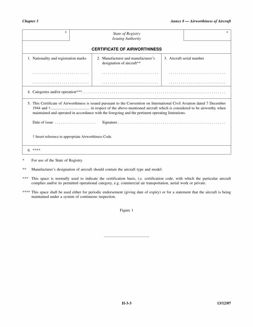
Chapter 3 Annex 8 — Airworthiness of Aircraft
II-3-3 13/12/07
* For use of the State of Registry.
** Manufacturer’s designation of aircraft should contain the aircraft type and model.
*** This space is normally used to indicate the certification basis, i.e. certification code, with which the particular aircraftcomplies and/or its permitted operational category, e.g. commercial air transportation, aerial work or private.
**** This space shall be used either for periodic endorsement (giving date of expiry) or for a statement that the aircraft is beingmaintained under a system of continuous inspection.
Figure 1
* State of RegistryIssuing Authority
CERTIFICATE OF AIRWORTHINESS
*
1. Nationality and registration marks
. . . . . . . . . . . . . . . . . . . . . . . . . . . . .
. . . . . . . . . . . . . . . . . . . . . . . . . . . . .
2. Manufacturer and manufacturer’s designation of aircraft**
. . . . . . . . . . . . . . . . . . . . . . . . . . . . .
. . . . . . . . . . . . . . . . . . . . . . . . . . . . .
3. Aircraft serial number
. . . . . . . . . . . . . . . . . . . . . . . . . . . . .
. . . . . . . . . . . . . . . . . . . . . . . . . . . . .
4. Categories and/or operation***. . . . . . . . . . . . . . . . . . . . . . . . . . . . . . . . . . . . . . . . . . . . . . . . . . . . . . . . . . . . . . . . . . . . . . . . .
5. This Certificate of Airworthiness is issued pursuant to the Convention on International Civil Aviation dated 7 December1944 and †........................................ in respect of the above-mentioned aircraft which is considered to be airworthy whenmaintained and operated in accordance with the foregoing and the pertinent operating limitations.
Date of issue . . . . . . . . . . . . . . . . . . . . . Signature . . . . . . . . . . . . . . . . . . . . . . . . . . . . . . . . . . . . . . . . . . . . . . . . . . . . . . .
† Insert reference to appropriate Airworthiness Code.
6. ****
ANNEX 8 II-4-1 13/12/07
CHAPTER 4. CONTINUING AIRWORTHINESS OF AIRCRAFT
4.1 Applicability
The Standards of this chapter are applicable to all aircraft.
4.2 Responsibilities of Contracting Statesin respect of continuing airworthiness
Note.— Guidance on continuing airworthiness require-ments is contained in the Airworthiness Manual (Doc 9760).
4.2.1 State of Design
4.2.1.1 The State of Design of an aircraft shall:
a) transmit to every Contracting State which has in accor-dance with 4.2.3 a) advised the State of Design that ithas entered the aircraft on its register, and to any otherContracting State upon request, any generally applicableinformation which it has found necessary for thecontinuing airworthiness of the aircraft, including itsengines and propellers when applicable, and for the safeoperation of the aircraft, (hereinafter called mandatorycontinuing airworthiness information) and notificationof the suspension or revocation of a Type Certificate;
Note 1.— The term “mandatory continuing airwor-thiness information” is intended to include mandatoryrequirements for modification, replacement of parts orinspection of aircraft and amendment of operating lim-itations and procedures. Among such information is thatissued by Contracting States in the form of airworthi-ness directives.
Note 2.— The Continuing Airworthiness of Aircraftin Service (Cir 95) provides the necessary informationto assist Contracting States in establishing contact withcompetent authorities of other Contracting States forthe purpose of maintaining continuing airworthiness ofaircraft in service.
b) ensure that, in respect of aeroplanes over 5 700 kg andhelicopters over 3 175 kg maximum certificated take-off mass, there exists a system for:
i) receiving information submitted in accordance with4.2.3 f);
ii) deciding if and when airworthiness action is needed;
iii) developing the necessary airworthiness actions; and
iv) promulgating the information on those actionsincluding that required in 4.2.1.1 a);
c) ensure that, in respect of aeroplanes over 5 700 kgmaximum certificated take-off mass, there exists acontinuing structural integrity programme to ensure theairworthiness of the aeroplane. The programme shallinclude specific information concerning corrosionprevention and control; and
d) ensure that, where the State of Manufacture of anaircraft is other than the State of Design, there is anagreement acceptable to both States to ensure that themanufacturing organization cooperates with the organ-ization responsible for the type design in assessinginformation received on experience with operating theaircraft.
4.2.1.2 The State of Design of an engine or a propeller,where it is different from the State of Design of the aircraft,shall transmit any continuing airworthiness information to theState of Design of the aircraft and to any other ContractingState upon request.
4.2.2 State of Manufacture
The State of Manufacture of an aircraft shall ensure that whereit is not the State of Design there is an agreement acceptableto both States to ensure that the manufacturing organizationcooperates with the organization responsible for the typedesign in assessing information received on experience withoperating the aircraft.
4.2.3 State of Registry
The State of Registry shall:
a) ensure that, when it first enters on its register an aircraftof a particular type for which it is not the State ofDesign and issues or validates a Certificate of Air-worthiness in accordance with 3.2 of this part, it shalladvise the State of Design that it has entered such anaircraft on its register;
b) determine the continuing airworthiness of an aircraft inrelation to the appropriate airworthiness requirements inforce for that aircraft;

Annex 8 — Airworthiness of Aircraft Part II
13/12/07 II-4-2
c) develop or adopt requirements to ensure the continuingairworthiness of the aircraft during its service life,including requirements to ensure that the aircraft:
i) continues to comply with the appropriate airworthi-ness requirements after a modification, a repair or theinstallation of a replacement part; and
ii) is maintained in an airworthy condition and in com-pliance with the maintenance requirements ofAnnex 6, and where applicable, Parts III, IV and V ofthis Annex;
d) upon receipt of mandatory continuing airworthinessinformation from the State of Design, adopt the manda-tory information directly or assess the informationreceived and take appropriate action;
e) ensure the transmission to the State of Design of allmandatory continuing airworthiness information whichit, as the State of Registry, originated in respect of thataircraft; and
f) ensure that, in respect of aeroplanes over 5 700 kg andhelicopters over 3 175 kg maximum certificated take-offmass, there exists a system whereby information onfaults, malfunctions, defects and other occurrences thatcause or might cause adverse effects on the continuingairworthiness of the aircraft is transmitted to the organ-ization responsible for the type design of that aircraft.
Note.— Guidance on interpretation of “the organizationresponsible for the type design” is contained in the Airworthi-ness Manual (Doc 9760).
4.2.4 All Contracting States
Each Contracting State shall establish, in respect of aeroplanesover 5 700 kg and helicopters over 3 175 kg maximum certif-icated take-off mass, the type of service information that is tobe reported to its airworthiness authority by operators, organi-zations responsible for type design and maintenance organiza-tions. Procedures for reporting this information shall also beestablished.

ANNEX 8 IIIA-1-1 13/12/07
PART III. LARGE AEROPLANES
PART IIIA. AEROPLANES OVER 5 700 KG FOR WHICH APPLICATION FORCERTIFICATION WAS SUBMITTED ON OR AFTER 13 JUNE 1960
BUT BEFORE 2 MARCH 2004
Note.— The provisions of Part IIIA are the same as those contained in Part III of Annex 8, Ninth Edition (includingAmendment 99), except for modified applicability clauses and cross-references.
CHAPTER 1. GENERAL
1.1 Applicability
1.1.1 The Standards of this part, except for thosespecified in 8.4, are applicable in respect of all aeroplanesdesignated in 1.1.3 that are of types of which the prototypewas submitted to the appropriate national authorities for certi-fication on or after 13 June 1960, but before 2 March 2004.
1.1.2 The Standards specified in 8.4 of this part areapplicable in respect of all aeroplanes designated in 1.1.3 thatare of types of which the prototype was submitted to theappropriate national authorities for certification on or after22 March 1985, but before 2 March 2004.
1.1.3 Except for those Standards and RecommendedPractices which specify a different applicability, the Standardsand Recommended Practices of this part shall apply toaeroplanes of over 5 700 kg maximum certificated take-offmass intended for the carriage of passengers or cargo or mailin international air navigation.
Note.— The following Standards do not include quantita-tive specifications comparable to those found in nationalairworthiness codes. In accordance with 1.2.1 of Part II, theseStandards are to be supplemented by requirements established,adopted or accepted by Contracting States.
1.1.4 The level of airworthiness defined by the appropri-ate parts of the comprehensive and detailed national codereferred to in 1.2.1 of Part II for the aeroplanes designated in1.1.3 shall be at least substantially equivalent to the overalllevel intended by the broad Standards of this part.
1.1.5 Unless otherwise stated, the Standards apply to thecomplete aeroplane including power-units, systems andequipment.
1.2 Number of power-units
The aeroplane shall have not less than two power-units.
1.3 Operating limitations
1.3.1 Limiting conditions shall be established for theaeroplane, its power-units and its equipment (see 9.2). Com-pliance with the Standards of this part shall be establishedassuming that the aeroplane is operated within the limitationsspecified. The limitations shall be sufficiently removed fromany condition(s) prejudicial to the safety of the aeroplane torender the likelihood of accidents arising therefrom extremelyremote.
Note.— Guidance material concerning the expression“extremely remote” is contained in the Airworthiness Manual(Doc 9760).
1.3.2 Limiting ranges of any parameter whose variationmay compromise the safe operation of the aeroplane, e.g.mass, centre of gravity location, load distribution, speeds, andaltitude or pressure-altitude, shall be established within whichcompliance with all the pertinent Standards in this part isshown, except that combinations of conditions which arefundamentally impossible to achieve need not be considered.
Note 1.— The maximum operating mass and centre ofgravity limits may vary, for example, with each altitude andwith each separate operating condition, e.g. take-off, en route,landing.
Note 2.— The following items, for instance, may beconsidered as basic aeroplane limitations:
— maximum certificated take-off mass;
— maximum certificated taxiing mass;
— maximum certificated landing mass;
— maximum certificated zero fuel mass; and

Annex 8 — Airworthiness of Aircraft Part IIIA
13/12/07 IIIA-1-2
— most forward and rearward centre of gravity positions invarious configurations (take-off, en route, landing).
Note 3.— Maximum operating mass may be limited by theapplication of Noise Certification Standards (see Annex 16,Volume I, and Annex 6, Parts I and II).
1.4 Unsafe features and characteristics
Under all anticipated operating conditions, the aeroplane shallnot possess any feature or characteristic that renders it unsafe.
1.5 Proof of compliance
1.5.1 Compliance with the appropriate airworthinessrequirements shall be based on evidence either from tests,calculations, or calculations based on tests, provided that ineach case the accuracy achieved will ensure a level of air-worthiness equal to that which would be achieved were directtests conducted.
1.5.2 The tests of 1.5.1 shall be such as to provide reason-able assurance that the aeroplane, its components andequipment are reliable and function correctly under the antici-pated operating conditions.

ANNEX 8 IIIA-2-1 13/12/07
CHAPTER 2. FLIGHT
2.1 General
2.1.1 Compliance with the Standards prescribed inChapter 2 shall be established by flight or other tests conductedupon an aeroplane or aeroplanes of the type for which aCertificate of Airworthiness is sought, or by calculations basedon such tests, provided that the results obtained by calculationsare equal in accuracy to, or conservatively represent, the resultsof direct testing.
2.1.2 Compliance with each Standard shall be establishedfor all applicable combinations of aeroplane mass and centreof gravity position, within the range of loading conditions forwhich certification is sought.
2.1.3 Where necessary, appropriate aeroplane configur-ations shall be established for the determination of perform-ance in the various stages of flight and for the investigation ofthe aeroplane’s flying qualities.
2.2 Performance
2.2.1 General
2.2.1.1 Sufficient data on the performance of theaeroplane shall be determined and scheduled in the flightmanual to provide operators with the necessary information forthe purpose of determining the total mass of the aeroplane onthe basis of the values, peculiar to the proposed flight, of therelevant operational parameters, in order that the flight may bemade with reasonable assurance that a safe minimum perfor-mance for that flight will be achieved.
2.2.1.2 Achieving the performance scheduled for theaeroplane shall take into consideration human performanceand in particular shall not require exceptional skill or alertnesson the part of the flight crew.
Note.— Guidance material on human performance can befound in the Human Factors Training Manual (Doc 9683).
2.2.1.3 The scheduled performance of the aeroplane shallbe consistent with compliance with 1.3.1 and with theoperation in logical combinations of those of the aeroplane’ssystems and equipment, the operation of which may affectperformance.
2.2.2 Minimum performance
At the maximum mass scheduled (see 2.2.3) for take-off andfor landing as functions of the aerodrome elevation orpressure-altitude either in the standard atmosphere or inspecified still air atmospheric conditions, and, for seaplanes, inspecified conditions of smooth water, the aeroplane shall becapable of accomplishing the minimum performancesspecified in 2.2.2.1 and 2.2.2.2, respectively, not consideringobstacles, or runway or water run length.
Note.— This Standard permits the maximum take-off massand maximum landing mass to be scheduled in the aeroplaneflight manual against, for example:
— aerodrome elevation, or
— pressure-altitude at aerodrome level, or
— pressure-altitude and atmospheric temperature at aero-drome level,
so as to be readily usable when applying the national code onaeroplane performance operating limitations.
2.2.2.1 Take-off
a) The aeroplane shall be capable of taking off assuming thecritical power-unit to fail (see 2.2.3), the remainingpower-units being operated within their take-off powerlimitations.
b) After the end of the period during which the take-off powermay be used, the aeroplane shall be capable of continuingto climb, with the critical power-unit inoperative and theremaining power-units operated within their maximumcontinuous power limitations, up to a height that it canmaintain and at which it can carry out a circuit of theaerodrome.
c) The minimum performance at all stages of take-off andclimb shall be sufficient to ensure that under conditions ofoperation departing slightly from the idealized conditionsfor which data are scheduled (see 2.2.3), the departure fromthe scheduled values is not disproportionate.
2.2.2.2 Landing
a) Starting from the approach configuration and with thecritical power-unit inoperative, the aeroplane shall be

Annex 8 — Airworthiness of Aircraft Part IIIA
13/12/07 IIIA-2-2
capable, in the event of a missed approach, of continuingthe flight to a point from which a fresh approach can bemade.
b) Starting from the landing configuration, the aeroplaneshall be capable, in the event of a balked landing, ofmaking a climb-out, with all power-units operating.
2.2.3 Scheduling of performance
Performance data shall be determined and scheduled in theflight manual so that their application by means of theoperating rules to which the aeroplane is to be operated inaccordance with 5.2 of Annex 6, Part I, will provide a saferelationship between the performance of the aeroplane and theaerodromes and routes on which it is capable of beingoperated. Performance data shall be determined and scheduledfor the following stages for the ranges of mass, altitude orpressure-altitude, wind velocity, gradient of the take-off andlanding surface for landplanes; water surface conditions,density of water and strength of current for seaplanes; and forany other operational variables for which the aeroplane is to becertificated.
2.2.3.1 Take-off. The take-off performance data shallinclude the accelerate-stop distance and the take-off path.
2.2.3.1.1 Accelerate-stop distance. The accelerate-stopdistance shall be the distance required to accelerate and stop,or, for a seaplane to accelerate and come to a satisfactorily lowspeed, assuming the critical power-unit to fail suddenly at apoint not nearer to the start of the take-off than that assumedwhen determining the take-off path (see 2.2.3.1.2).
2.2.3.1.2 Take-off path. The take-off path shall comprisethe ground or water run, initial climb and climb-out, assuming the critical power-unit to fail suddenlyduring the take-off (see 2.2.3.1.1). The take-off path shallbe scheduled up to a height that the aeroplane canmaintain and at which it can carry out a circuit of theaerodrome. The climb-out shall be made at a speed not lessthan the take-off safety speed as determined in accordancewith 2.3.1.3.
2.2.3.2 En route. The en-route climb performance shallbe the climb (or descent) performance with the aeroplane inthe en-route configuration with:
a) the critical power-unit inoperative; and
b) the two critical power-units inoperative in the case ofaeroplanes having three or more power-units.
The operating engines shall not exceed maximum continuouspower.
2.2.3.3 Landing. The landing distance shall be thehorizontal distance traversed by the aeroplane from a point on
the approach flight path at a selected height above the landingsurface to the point on the landing surface at which theaeroplane comes to a complete stop, or, for a seaplane, comesto a satisfactorily low speed. The selected height above thelanding surface and the approach speed shall be appropriatelyrelated to operating practices. This distance may be supple-mented by such distance margin as may be necessary; if so, theselected height above the landing surface, the approach speedand the distance margin shall be appropriately interrelated andshall make provision for both normal operating practices andreasonable variations therefrom.
Note.— If the landing distance includes the distance marginspecified in this Standard, it is not necessary to allow for theexpected variations in the approach and landing techniques inapplying 5.2.11 of Annex 6, Part I.
2.3 Flying qualities
The aeroplane shall comply with the Standards of 2.3 at allaltitudes up to the maximum anticipated altitude relevant tothe particular requirement in all temperature conditionsrelevant to the altitude in question and for which the aeroplaneis approved.
2.3.1 Controllability
The aeroplane shall be controllable and manoeuvrable underall anticipated operating conditions, and it shall be possible tomake smooth transitions from one flight condition to another(e.g. turns, sideslips, changes of engine power, changes ofaeroplane configurations) without requiring exceptional skill,alertness or strength on the part of the pilot even in the eventof failure of any power-unit. A technique for safely controllingthe aeroplane shall be established for all stages of flight andaeroplane configurations for which performance is scheduled.
Note.— This Standard is intended, among other things, torelate to operation in conditions of no appreciableatmospheric turbulence and also to ensure that there is noundue deterioration of the flying qualities in turbulent air.
2.3.1.1 Controllability on the ground (or water). Theaeroplane shall be controllable on the ground (or on the water)during taxiing, take-off and landing under the anticipatedoperating conditions.
2.3.1.2 Controllability during take-off. The aeroplaneshall be controllable in the event of sudden failure of thecritical power-unit at any point in the take-off, when theaeroplane is handled in the manner associated with the sched-uling of take-off paths and accelerate-stop distances.
2.3.1.3 Take-off safety speed. The take-off safetyspeeds assumed when the performance of the aeroplane (afterleaving the ground or water) during the take-off is determined
Chapter 2 Annex 8 — Airworthiness of Aircraft
IIIA-2-3 13/12/07
shall provide an adequate margin above the stall and abovethe minimum speed at which the aeroplane remains control-lable after sudden failure of the critical power-unit.
2.3.2 Trim
The aeroplane shall have such trim and other characteristics asto ensure that the demands made on the pilot’s attention andability to maintain a desired flight condition are not excessivewhen account is taken of the stage of flight at which thesedemands occur and their duration. This shall apply both innormal operation and in the conditions associated with thefailure of one or more power-units for which performancecharacteristics are established.
2.3.3 Stability
The aeroplane shall have such stability in relation to its otherflight characteristics, performance, structural strength, andmost probable operating conditions (e.g. aeroplane configura-tions and speed ranges) as to ensure that demands made on thepilot’s powers of concentration are not excessive when thestage of the flight at which these demands occur and theirduration are taken into account. The stability of the aeroplaneshall not, however, be such that excessive demands aremade on the pilot’s strength or that the safety of the aeroplaneis prejudiced by lack of manoeuvrability in emergencyconditions.
2.3.4 Stalling
2.3.4.1 Stall warning. When the aeroplane approaches astall both in straight and turning flight with all power-unitsoperating and with one power-unit inoperative, a clear and
distinctive stall warning shall be apparent to the pilot with theaeroplane in all permissible configurations and powers, exceptthose which are not considered to be essential for safe flying.The stall warning and other characteristics of the aeroplaneshall be such as to enable the pilot to arrest the developmentof the stall after the warning begins and, without altering theengine power, to maintain full control of the aeroplane.
2.3.4.2 Behaviour following a stall. In any configurationand power in which it is considered that the ability to recoverfrom a stall is essential, the behaviour of the aeroplanefollowing a stall shall not be so extreme as to make difficult aprompt recovery without exceeding the airspeed or strengthlimitations of the aeroplane. It shall be acceptable to throttleback the operating power-units during recovery from the stall.
2.3.4.3 Stalling speeds. The stalling speeds or minimumsteady flight speeds in configurations appropriate for eachstage of flight (e.g. take-off, en route, landing) shall be estab-lished. One of the values of the power used in establishing thestalling speeds shall be not more than that necessary to givezero thrust at a speed just above the stall.
2.3.5 Flutter and vibration
It shall be demonstrated by suitable tests that all parts of theaeroplane are free from flutter and excessive vibration in allaeroplane configurations under all speed conditions within theoperating limitations of the aeroplane (see 1.3.2). There shallbe no buffeting severe enough to interfere with control of theaeroplane, to cause structural damage or to cause excessivefatigue to the flight crew.
Note.— Buffeting as a stall warning is considered desirableand discouragement of this type of buffeting is not intended.
ANNEX 8 IIIA-3-1 13/12/07
CHAPTER 3. STRUCTURES
3.1 General
The Standards of Chapter 3 apply to the aeroplane structureconsisting of all portions of the aeroplane, the failure of whichwould seriously endanger the aeroplane.
3.1.1 Mass and mass distribution
Unless otherwise stated, all structural Standards shall becomplied with when the mass is varied over the applicablerange and is distributed in the most adverse manner, within theoperating limitations on the basis of which certification issought.
3.1.2 Limit loads
Except as might be otherwise qualified, the external loads andthe corresponding inertia loads, or resisting loads obtained forthe various loading conditions prescribed in 3.3, 3.4 and 3.5shall be considered as limit loads.
3.1.3 Strength and deformation
In the various loading conditions prescribed in 3.3, 3.4 and3.5, no part of the aeroplane structure shall sustain detrimentaldeformation at any load up to and including the limit load, andthe aeroplane structure shall be capable of supporting theultimate load.
3.2 Airspeeds
3.2.1 Design airspeeds
Design airspeeds shall be established for which the aeroplanestructure is designed to withstand the corresponding man-oeuvring and gust loads in accordance with 3.3. In establishingthe design airspeeds, consideration shall be given to thefollowing speeds:
a) VA, the design manoeuvring speed;
b) VB, the speed at which the maximum vertical gustvelocity assumed in accordance with 3.3.2 can bewithstood;
c) VC, a speed not expected to be exceeded in normalcruising flight taking into account possible effects ofupsets when flying in turbulent conditions;
d) VD, maximum dive speed, sufficiently greater than thespeed in c), to make it unlikely that such a design speedwould be exceeded as a result of inadvertent speedincreases in the anticipated operating conditions, takinginto account the flying qualities and other characteristicsof the aeroplane;
e) VE1 to VEn, maximum speeds at which flaps and landinggears may be extended or other configuration changesbe made.
The speeds VA, VB, VC, and VE in a), b), c) and e) shall besufficiently greater than the stalling speed of the aeroplane tosafeguard against loss of control in turbulent air.
3.2.2 Limiting airspeeds
Limiting airspeeds, based on the corresponding designairspeeds with safety margins, where appropriate, in accord-ance with 1.3.1, shall be included in the aeroplane flightmanual as part of the operating limitations (see 9.2.2).
3.3 Flight loads
The flight loading conditions of 3.3.1, 3.3.2 and 3.5 shall beconsidered for the range of mass and mass distributionsprescribed in 3.1.1 and at airspeeds established in accordancewith 3.2.1. Asymmetrical as well as symmetrical loading shallbe taken into account. The air, inertia and other loads resultingfrom the specified loading conditions shall be distributed so asto approximate actual conditions closely or to represent themconservatively.
3.3.1 Manoeuvring loads
Manoeuvring loads shall be computed on the basis of man-oeuvring load factors appropriate to the manoeuvres permittedby the operating limitations. They shall not be less than valuesthat experience indicates will be adequate for the anticipatedoperating conditions.
3.3.2 Gust loads
Gust loads shall be computed for vertical and horizontal gustvelocities and gradients that statistics or other evidence indi-cate will be adequate for the anticipated operating conditions.

Annex 8 — Airworthiness of Aircraft Part IIIA
13/12/07 IIIA-3-2
3.4 Ground and water loads
The structure shall be able to withstand all the loads due to thereactions of the ground and water surface that are likely toarise during taxiing, take-off and landing.
3.4.1 Landing conditions
The landing conditions at the design take-off mass and at thedesign landing mass shall include such symmetrical andasymmetrical attitudes of the aeroplane at ground or watercontact, such velocities of descent, and such other factorsaffecting the loads imposed upon the structure as might bepresent in the anticipated operating conditions.
3.5 Miscellaneous loads
In addition to or in conjunction with the manoeuvring and gustloads and with the ground and water loads, consideration shallbe given to all other loads (flight control loads, cabinpressures, effects of engine operation, loads due to changes of
configuration, etc.) that are likely to occur in the anticipatedoperating conditions.
3.6 Flutter, divergence and vibration
The aeroplane structure shall be designed to be free fromflutter, structural divergence (i.e. unstable structural distortiondue to aerodynamic loading), and loss of control due to struc-tural deformation, at speeds within and sufficiently beyond theoperating limitations to comply with 1.3.1. Adequate strengthshall be provided to withstand the vibration and buffeting thatmight occur in the anticipated operating conditions.
3.7 Fatigue strength
The strength and fabrication of the aeroplane shall be such asto ensure that the probability of disastrous fatigue failure of theaeroplane’s structure under repeated loads and vibratory loadsin the anticipated operating conditions is extremely remote.
Note.— Guidance material concerning the expression“extremely remote” is contained in the Airworthiness Manual(Doc 9760).

ANNEX 8 IIIA-4-1 13/12/07
CHAPTER 4. DESIGN AND CONSTRUCTION
4.1 General
Details of design and construction shall be such as to givereasonable assurance that all aeroplane parts will functioneffectively and reliably in the anticipated operating conditions.They shall be based upon practices that experience has provento be satisfactory or that are substantiated by special tests or byother appropriate investigations or both. They shall alsoconsider Human Factors principles.
Note.— Guidance material on Human Factors principles canbe found in the Human Factors Training Manual (Doc 9683).
4.1.1 Substantiating tests
The functioning of all moving parts essential to the safeoperation of the aeroplane shall be demonstrated by suitabletests in order to ensure that they will function correctly underall operating conditions for such parts.
4.1.2 Materials
All materials used in parts of the aeroplane essential for itssafe operation shall conform to approved specifications. Theapproved specifications shall be such that materials acceptedas complying with the specifications will have the essentialproperties assumed in the design.
4.1.3 Manufacturing methods
The methods of manufacturing and assembly shall be such asto produce a consistently sound structure which shall bereliable with respect to maintenance of strength in service.
4.1.4 Protection
The structure shall be protected against deterioration or loss ofstrength in service due to weathering, corrosion, abrasion orother causes, which could pass unnoticed, taking into accountthe maintenance the aeroplane will receive.
4.1.5 Inspection provisions
Adequate provision shall be made to permit any necessaryexamination, replacement or reconditioning of parts of theaeroplane that require such attention, either periodically orafter unusually severe operations.
4.1.6 Systems design features
Special consideration shall be given to design features thataffect the ability of the flight crew to maintain controlledflight. This shall include at least the following:
a) Controls and control systems. The design of the controlsand control systems shall be such as to minimize thepossibility of jamming, inadvertent operations, andunintentional engagement of control surface lockingdevices.
b) System survivability.
1) For aeroplanes of a maximum certificated take-offmass in excess of 45 500 kg or with a passengerseating capacity greater than 60 and for which theapplication for certification was submitted on or after12 March 2000, aeroplane systems shall be designed,arranged and physically separated to maximize thepotential for continued safe flight and landing afterany event resulting in damage to the aeroplanestructure or systems.
2) Recommendation.— For aeroplanes of a maximumcertificated take-off mass in excess of 5 700 kg butnot exceeding 45 500 kg and for which theapplication for certification was submitted on orafter 12 March 2000, aeroplane systems should bedesigned, arranged and physically separated to max-imize the potential for continued safe flight andlanding after any event resulting in damage to theaeroplane structure or systems.
c) Crew environment. The design of the flight crewcompartment shall be such as to minimize the possibilityof incorrect or restricted operation of the controls by thecrew, due to fatigue, confusion or interference. Con-sideration shall be given at least to the following: layoutand identification of controls and instruments, rapididentification of emergency situations, sense of controls,ventilation, heating and noise.
d) Pilot vision. The arrangement of the pilot compartmentshall be such as to afford a sufficiently extensive, clearand undistorted field of vision for the safe operation ofthe aeroplane, and to prevent glare and reflections thatwould interfere with the pilot’s vision. The designfeatures of the pilot windshield shall permit, underprecipitation conditions, sufficient vision for the normalconduct of flight and for the execution of approachesand landings.

Annex 8 — Airworthiness of Aircraft Part IIIA
13/12/07 IIIA-4-2
e) Provision for emergencies. Means shall be providedwhich shall either automatically prevent, or enable theflight crew to deal with, emergencies resulting fromforeseeable failures of equipment and systems, thefailure of which would endanger the aeroplane. Reason-able provisions shall be made for continuation of essen-tial services following power-unit or systems’ failures tothe extent that such failures are catered for in theperformance and operating limitations specified in theStandards in this Annex and in Annex 6, Parts I and II.
f) Fire precautions. The design of the aeroplane and thematerials used in its manufacture, including cabininterior furnishing materials replaced during majorrefurbishing, shall be such as to minimize the possibilityof in-flight and ground fires and also to minimize theproduction of smoke and toxic gases in the event of afire. Means shall be provided to contain or to detect andextinguish such fires as might occur in such a way thatno additional danger to the aeroplane is caused.
g) Fire suppression. For aeroplanes for which theapplication for certification was submitted on or after12 March 2000, cargo compartment fire suppressionsystems, including their extinguishing agents, shall bedesigned so as to take into account a sudden andextensive fire such as could be caused by an explosiveor incendiary device or dangerous goods.
h) Incapacitation of occupants.
1) For aeroplanes of a maximum certificated take-offmass in excess of 45 500 kg or with a passengerseating capacity greater than 60 and for which theapplication for certification was submitted on or after12 March 2000, design precautions shall be taken toprotect against possible instances of cabin depressur-ization and against the presence of smoke or othertoxic gases, including those caused by explosive orincendiary devices or dangerous goods, which couldincapacitate the occupants of the aeroplane.
2) Recommendation.— For aeroplanes of a maximumcertificated take-off mass in excess of 5 700 kg butnot exceeding 45 500 kg and for which the appli-cation for certification was submitted on or after12 March 2000, design precautions should be takento protect against possible instances of cabindepressurization and against the presence of smokeor other toxic gases, including those caused byexplosive or incendiary devices or dangerous goods,which could incapacitate the occupants of theaeroplane.
i) Protection of the flight crew compartment from smokeand fumes.
1) For aeroplanes of a maximum certificated take-offmass in excess of 45 500 kg or with a passengerseating capacity greater than 60 and for which theapplication for certification was submitted on or after12 March 2000, means shall be provided to minimizeentry into the flight crew compartment of smoke,fumes and noxious vapours generated by anexplosion or fire on the aeroplane.
2) Recommendation.— For aeroplanes of a maximumcertificated take-off mass in excess of 5 700 kg butnot exceeding 45 500 kg and for which theapplication for certification was submitted on orafter 12 March 2000, means should be provided tominimize entry into the flight crew compartment ofsmoke, fumes and noxious vapours generated by anexplosion or fire on the aeroplane.
4.1.7 Emergency landing provisions
4.1.7.1 Provisions shall be made in the design of theaeroplane to protect the occupants, in the event of an emergencylanding, from fire and from the direct effects of decelerationforces as well as from injuries arising from the effect ofdeceleration forces on the aeroplane’s interior equipment.
4.1.7.2 Facilities shall be provided for the rapid evacu-ation of the aeroplane in conditions likely to occur followingan emergency landing. Such facilities shall be related to thepassenger and crew capacity of the aeroplane.
4.1.7.3 The interior layout of the cabin and the positionand number of emergency exits, including the means oflocating and illuminating the escape paths and exits, shall besuch as to facilitate rapid evacuation of the aeroplane inconditions likely to occur following an emergency landing.
4.1.7.4 On aeroplanes certificated for ditching conditions,provisions shall be made in the design to give maximumpracticable assurance that safe evacuation from the aeroplaneof passengers and crew can be executed in case of ditching.
4.1.8 Ground handling
Adequate provisions shall be made in the design to minimizethe risk that ground-handling operations (e.g. towing, jacking)may cause damage, which could pass unnoticed, to the parts ofthe aeroplane essential for its safe operation. The protectionthat any limitations and instructions for such operations mightprovide may be taken into account.

ANNEX 8 IIIA-5-1 13/12/07
CHAPTER 5. ENGINES
5.1 Scope
The Standards of Chapter 5 shall apply to engines of all typesthat are used on the aeroplane as primary propulsion units.
5.2 Design, constructionand functioning
The engine complete with accessories shall be designed andconstructed so as to function reliably within its operatinglimitations under the anticipated operating conditions whenproperly installed in the aeroplane in accordance withChapter 7 and, if applicable, fitted with a suitable propeller.
5.3 Declared ratings, conditionsand limitations
The power ratings and the conditions of the atmosphere uponwhich they are based and all operating conditions andlimitations which are intended to govern the operation of theengine shall be declared.
5.4 Tests
An engine of the type shall complete satisfactorily such testsas are necessary to verify the validity of the declared ratings,conditions and limitations and to ensure that it will operatesatisfactorily and reliably. The tests shall include at least thefollowing:
a) Power calibration. Tests shall be conducted to establishthe power or thrust characteristics of the engine whennew and also after the tests in b) and c). There shall beno excessive decrease in power at the conclusion of allthe tests specified.
b) Operation. Tests shall be conducted to ensure thatstarting, idling, acceleration, vibration, overspeedingand other characteristics are satisfactory and to demon-strate adequate margins of freedom from detonation,surge or other detrimental conditions as may beappropriate to the particular type engine.
c) Endurance. Tests of sufficient duration shall be con-ducted at such powers, thrust, speeds and otheroperating conditions as are necessary to demonstratereliability and durability of the engine. They shall alsoinclude operation under conditions in excess of thedeclared limits to the extent that such limitations mightbe exceeded in actual service.
ANNEX 8 IIIA-6-1 13/12/07
CHAPTER 6. PROPELLERS
6.1 Scope
The Standards of Chapter 6 shall apply to propellers of alltypes.
6.2 Design, construction and functioning
The propeller assembly complete with accessories shall bedesigned and constructed so as to function reliably within itsoperating limitations under the anticipated operating condi-tions when properly fitted to the engine and installed in theaeroplane in accordance with Chapter 7.
6.3 Declared ratings, conditions and limitations
The power ratings and all operating conditions and limitationswhich are intended to govern the operation of the propellershall be declared.
6.4 Tests
A propeller of the type shall complete satisfactorily such testsas are necessary to ensure that it will operate satisfactorily andreliably within the declared ratings, conditions and limitations.The tests shall include at least the following:
a) Operation. Tests shall be conducted to ensure thatstrength vibration and overspeeding characteristics aresatisfactory and to demonstrate proper and reliablefunctioning of pitch changing and control mechanisms.
b) Endurance. Tests of sufficient duration shall beconducted at such powers, speeds and other operatingconditions as are necessary to demonstrate reliabilityand durability of the propeller.

ANNEX 8 IIIA-7-1 13/12/07
CHAPTER 7. POWERPLANT INSTALLATION
7.1 General
7.1.1 Applicable Standards
The powerplant installation shall comply with the Standards ofChapter 4 and with the Standards of this chapter.
7.1.2 Compliance with engine andpropeller limitations
The powerplant installation shall be so designed that theengines and propellers (if applicable) are capable of beingused in the anticipated operating conditions. In conditionsestablished in the aeroplane flight manual, the aeroplane shallbe capable of being operated without exceeding the limitationsestablished for the engines and propellers in accordance withChapters 5, 6 and 7.
7.1.3 Control of engine rotation
In those installations where continued rotation of a failedengine would increase the hazard of fire or of a seriousstructural failure, means shall be provided for the crew to stopthe rotation of the engine in flight or to reduce it to a safelevel.
7.1.4 Engine restarting
Means shall be provided for restarting an engine in flight ataltitudes up to a declared maximum altitude.
7.2 Arrangement and functioning
7.2.1 Independence of power-units
The powerplant shall be arranged and installed so that eachpower-unit together with its associated systems is capable ofbeing controlled and operated independently from the othersand so that there is at least one arrangement of the power-plant and systems in which any failure, unless the probabilityof its occurrence is extremely remote, cannot result in a lossof more power than that resulting from complete failure ofthe critical power-unit.
7.2.2 Propeller vibration
The propeller vibration stresses shall be determined and shallnot exceed values that have been found safe for operationwithin the operating limitations established for the aeroplane.
7.2.3 Cooling
The cooling system shall be capable of maintaining power-plant temperatures within the established limits (see 7.1.2) atambient air temperatures up to the maximum air temperatureappropriate to the intended operation of the aeroplane. Themaximum and, if necessary, minimum ambient air temperaturefor which the powerplant has been established as beingsuitable shall be scheduled in the aeroplane flight manual.
7.2.4 Associated systems
The fuel, oil, air induction, and other systems associated withthe powerplant shall be capable of supplying each engine inaccordance with its established requirements, under allconditions affecting the functioning of the systems (e.g. enginepower, aeroplane attitudes and accelerations, atmosphericconditions, fluid temperatures) within the anticipated operatingconditions.
7.2.5 Fire protection
For regions of the powerplant where the potential fire hazardsare particularly serious because of the proximity of ignitionsources to combustible materials, the following shall apply inaddition to the general Standard of 4.1.6 e).
a) Isolation. Such regions shall be isolated by fire-resistingmaterial from other regions of the aeroplane where thepresence of fire would jeopardize continued flight,taking into account the probable points of origin andpaths of propagation of fire.
b) Flammable fluids. Flammable fluid system componentslocated in such regions shall be capable of containingthe fluid when exposed to fire conditions. Means shallbe provided for the crew to shut off the flow offlammable fluids into such regions if a fire occurs.
c) Fire detection. A sufficient number of fire detectorsshall be provided and located to ensure rapid detectionof any fire that might occur in such regions.

Annex 8 — Airworthiness of Aircraft Part IIIA
13/12/07 IIIA-7-2
d) Fire extinguishment. Such regions shall be providedwith a fire extinguisher system capable of extinguishingany fire likely to occur therein, unless the degree ofisolation, quantity of combustibles, fire resistance of thestructure, and other factors are such that any fire likelyto occur in the region would not jeopardize the safety ofthe aeroplane.

ANNEX 8 IIIA-8-1 13/12/07
CHAPTER 8. INSTRUMENTS AND EQUIPMENT
8.1 Required instrumentsand equipment
The aeroplane shall be provided with approved instrumentsand equipment necessary for the safe operation of theaeroplane in the anticipated operating conditions. These shallinclude the instruments and equipment necessary to enable thecrew to operate the aeroplane within its operating limitations.
Note 1.— Instruments and equipment additional to theminimum necessary for the issuance of a Certificate of Air-worthiness are prescribed in Annex 6, Parts I and II, forparticular circumstances or on particular kinds of routes.
Note 2.— Instruments and equipment design shall observeHuman Factors principles.
Note 3.— Guidance material on Human Factors principlescan be found in the Human Factors Training Manual(Doc 9683) and in the Human Factors Guidelines for AirTraffic Management (ATM) Systems (Doc 9758).
8.2 Installation
Instrument and equipment installations shall comply with theStandards of Chapter 4.
8.3 Safety andsurvival equipment
Prescribed safety and survival equipment that the crew orpassengers are expected to use or operate at the time of anemergency shall be reliable, readily accessible and easilyidentified, and its method of operation shall be plainly marked.
*8.4 Navigation lightsand anti-collision lights
8.4.1 The lights required by Annex 2 — Rules of the Airto be displayed by aeroplanes in flight or operating on themovement area of an aerodrome shall have intensities,colours, fields of coverage and other characteristics such thatthey furnish the pilot of another aircraft or personnel on theground with as much time as possible for interpretation andfor subsequent manoeuvre necessary to avoid a collision. Inthe design of such lights, due account shall be taken of theconditions under which they may reasonably be expected toperform these functions.
Note 1.— It is likely that lights will be viewed against avariety of backgrounds, such as typical city lighting, clearstarry sky, moonlit water and daytime conditions of low back-ground luminance. Furthermore, collision risk situations aremost likely to arise in terminal control areas in which aircraftare manoeuvring in the intermediate and lower flight levels atclosing speeds that are unlikely to exceed 900 km/h (500 kt).
Note 2.— See the Airworthiness Manual (Doc 9760) fordetailed technical specifications for exterior lights foraeroplanes.
8.4.2 Lights shall be installed in aeroplanes so as tominimize the possibility that they will:
a) adversely affect the satisfactory performance of theflight crews’ duties; or
b) subject an outside observer to harmful dazzle.
Note.— In order to avoid the effects mentioned in8.4.2, it will be necessary in some cases to provide meanswhereby the pilot can switch off or reduce the intensity of theflashing lights.
* Please refer to 1.1.2 of this part.

ANNEX 8 IIIA-9-1 13/12/07
CHAPTER 9. OPERATING LIMITATIONS AND INFORMATION
9.1 General
The operating limitations within which compliance with theStandards of this Annex is determined, together with any otherinformation necessary to the safe operation of the aeroplane,shall be made available by means of an aeroplane flightmanual, markings and placards, and such other means as mayeffectively accomplish the purpose. The limitations and infor-mation shall include at least those prescribed in 9.2, 9.3 and9.4.
9.2 Operating limitations
Limitations which there is a risk of exceeding in flight andwhich are defined quantitatively shall be expressed in suitableunits and corrected if necessary for errors in measurements sothat the flight crew can, by reference to the instrumentsavailable to them, readily determine when the limitations arereached.
9.2.1 Loading limitations
The loading limitations shall include all limiting masses,centres of gravity positions, mass distributions and floorloadings (see 1.3.2).
9.2.2 Airspeed limitations
The airspeed limitations shall include all speeds (see 3.2) thatare limiting from the standpoint of structural integrity or flyingqualities of the aeroplane, or from other considerations. Thesespeeds shall be identified with respect to the appropriateaeroplane configurations and other pertinent factors.
9.2.3 Powerplant limitations
The powerplant limitations shall include all those establishedfor the various powerplant components as installed in theaeroplane (see 7.1.2 and 7.2.3).
9.2.4 Limitations on equipment and systems
The limitations on equipment and systems shall include allthose established for the various equipment and systems asinstalled in the aeroplane.
9.2.5 Miscellaneous limitations
Miscellaneous limitations shall include any necessary limi-tations with respect to conditions found to be prejudicial to thesafety of the aeroplane (see 1.3.1).
9.2.6 Flight crew limitations
The flight crew limitations shall include the minimum numberof flight crew personnel necessary to operate the aeroplane,having regard, among other things, to the accessibility to theappropriate crew members of all necessary controls andinstruments and to the execution of the established emergencyprocedures.
Note.— See Annex 6 — Operation of Aircraft, Parts I andII, for the circumstances in which the flight crew shall includemembers in addition to the minimum flight crew defined in thisAnnex.
9.2.7 Flying time limitation after systemor power-unit failure
The systems limitations shall include the maximum flying timefor which system reliability has been established in relation tothe approval of operations by aeroplanes with two turbinepower-units beyond the threshold time established in accord-ance with 4.7 of Annex 6, Part I.
Note.— The maximum time established in accordance with4.7 of Annex 6, Part I, for a particular route may be less thanthat determined in accordance with 9.2.7 because of theoperational considerations involved.
9.3 Operating information and procedures
9.3.1 Types of eligible operations
There shall be listed the particular types of operations, as maybe defined in Annex 6, Parts I and II, or be generallyrecognized, for which the aeroplane has been shown to beeligible by virtue of compliance with the appropriate air-worthiness requirements.
9.3.2 Loading information
The loading information shall include the empty mass of theaeroplane, together with a definition of the condition of the

Annex 8 — Airworthiness of Aircraft Part IIIA
13/12/07 IIIA-9-2
aeroplane at the time of weighing, the corresponding centre ofgravity position, and the reference points and datum lines towhich the centre of gravity limits are related.
Note.— Usually the empty mass excludes the mass of thecrew and payload, the usable fuel supply and the drainableoil; it includes the mass of all fixed ballast, unusable fuelsupply, undrainable oil, total quantity of engine coolant andtotal quantity of hydraulic fluid.
9.3.3 Operating procedures
A description shall be given of normal and emergencyoperating procedures which are peculiar to the particularaeroplane and necessary for its safe operation. These shallinclude procedures to be followed in the event of failure of oneor more power-units.
9.3.4 Handling information
Sufficient information shall be given on any significant orunusual features of the aeroplane characteristics. Those stall-ing speeds or minimum steady flight speeds required to beestablished by 2.3.4.3 shall be scheduled.
9.3.5 Least-risk bomb location
For aeroplanes of a maximum certificated take-off mass inexcess of 45 500 kg or with a passenger seating capacitygreater than 60 and for which the application for certificationwas submitted on or after 12 March 2000, a least-risk locationon the aeroplane shall be identified where a bomb or other
explosive device may be placed to minimize the effects on theaeroplane in the case of detonation.
9.4 Performance information
The performance of the aeroplane shall be scheduled inaccordance with 2.2. There shall be included informationregarding the various aeroplane configurations and powersinvolved and the relevant speeds, together with informationthat would assist the flight crew in attaining the performanceas scheduled.
9.5 Aeroplane flight manual
A flight manual shall be made available. It shall identifyclearly the specific aeroplane or series of aeroplanes to whichit is related. The flight manual shall include at least the limi-tations, information and procedures specified in this chapter.
9.6 Markings and placards
9.6.1 Markings and placards on instruments, equipment,controls, etc., shall include such limitations or information asnecessary for the direct attention of the flight crew duringflight.
9.6.2 Markings and placards or instructions shall beprovided to give any information that is essential to the groundcrew in order to preclude the possibility of mistakes in groundservicing (e.g. towing, refuelling) that could pass unnoticedand that could jeopardize the safety of the aeroplane insubsequent flights.

ANNEX 8 IIIA-10-1 13/12/07
CHAPTER 10. CONTINUING AIRWORTHINESS —MAINTENANCE INFORMATION
10.1 General
Information for use in developing procedures for maintainingthe aeroplane in an airworthy condition shall be made avail-able. The information shall include that described in 10.2, 10.3and 10.4.
10.2 Maintenance information
Maintenance information shall include a description of theaeroplane and recommended methods for the accomplishmentof maintenance tasks. Such information shall include guidanceon defect diagnosis.
10.3 Maintenance programmeinformation
Maintenance programme information shall include the main-tenance tasks and the recommended intervals at which thesetasks are to be performed.
10.4 Maintenance information resulting from the type design approval
Maintenance tasks and frequencies that have been specified asmandatory by the State of Design in approval of the typedesign shall be identified as such.
ANNEX 8 IIIA-11-1 13/12/07
CHAPTER 11. SECURITY
11.1 Aeroplanes used for domesticcommercial operations
Recommendation.— International Standards and Recom-mended Practices set forth in this chapter should be applied byall Contracting States for aeroplanes engaged in domesticcommercial operations (air services).
11.2 Least-risk bomb location
For aeroplanes of a maximum certificated take-off mass inexcess of 45 500 kg or with a passenger seating capacitygreater than 60 and for which the application for certificationwas submitted on or after 12 March 2000, consideration shallbe given during the design of the aeroplane to the provision ofa least-risk bomb location so as to minimize the effects of abomb on the aeroplane and its occupants.
11.3 Protection of the flight crew compartment
Recommendation.— In all aeroplanes, which are required byAnnex 6, Part I, Chapter 13 to have an approved flight crewcompartment door, and for which an application for amending
the Type Certificate to include a derivative type design issubmitted to the appropriate national authority, considerationshould be given to reinforcing the flight crew compartmentbulkheads, floors and ceilings so as to resist penetration bysmall arms fire and grenade shrapnel and to resist forcibleintrusions, if these areas are accessible in flight to passengersand cabin crew.
Note.— Standards and Recommended Practices concerningthe requirements for the flight crew compartment door in allcommercial passenger-carrying aeroplanes are contained inAnnex 6, Part I, Chapter 13.
11.4 Interior design
For aeroplanes of a maximum certificated take-off mass inexcess of 45 500 kg or with a passenger seating capacitygreater than 60 and for which the application for certificationwas submitted on or after 12 March 2000, consideration shallbe given to design features that will deter the easy conceal-ment of weapons, explosives or other dangerous objects onboard aircraft and that will facilitate search procedures forsuch objects.

ANNEX 8 IIIB-A-1 13/12/07
PART IIIB. AEROPLANES OVER 5 700 KG FOR WHICH APPLICATION FOR CERTIFICATION WAS SUBMITTED ON OR AFTER 2 MARCH 2004
SUB-PART A. GENERAL
A.1 Applicability
A.1.1 The Standards of this part are applicable in respectof all aeroplanes designated in A.1.2 for which an applicationfor the issue of a Type Certificate is submitted to the appropri-ate national authorities on or after 2 March 2004.
A.1.2 Except for those Standards and RecommendedPractices which specify a different applicability, the Standardsand Recommended Practices of this part shall apply to allaeroplanes over 5 700 kg maximum certificated take-off massintended for the carriage of passengers or cargo or mail ininternational air navigation.
Note 1.— The aeroplanes described in A.1.2 are known insome States as transport category aeroplanes.
Note 2.— The following Standards do not include quantita-tive specifications comparable to those found in nationalairworthiness codes. In accordance with 1.2.1 of Part II, theseStandards are to be supplemented by requirements established,adopted or accepted by Contracting States.
A.1.3 The level of airworthiness defined by the appropri-ate parts of the comprehensive and detailed national codereferred to in 1.2.1 of Part II for the aeroplanes designated inA.1.2 shall be at least substantially equivalent to the overalllevel intended by the broad Standards of this part.
A.1.4 Unless otherwise stated, the Standards apply to thecomplete aeroplane including power-units, systems andequipment.
A.2 Operating limitations
A.2.1 Limiting conditions shall be established for theaeroplane, its power-units and its equipment (see G.2).
Compliance with the Standards of this part shall be establishedassuming that the aeroplane is operated within the limitationsspecified. The limitations shall include a margin of safety torender the likelihood of accidents arising therefrom extremelyremote.
Note.— Guidance material concerning the expression“extremely remote” is contained in the Airworthiness Manual(Doc 9760).
A.2.2 Limiting ranges of any parameter whose variationmay compromise the safe operation of the aeroplane, e.g.mass, centre of gravity location, load distribution, speeds,ambient air temperature and altitude or pressure-altitude, shallbe established within which compliance with all the pertinentStandards in this part is shown.
Note.— Maximum operating mass may be limited by theapplication of Noise Certification Standards (see Annex 16,Volume I, and Annex 6, Parts I and II).
A.3 Unsafe features and characteristics
Under all anticipated operating conditions, the aeroplane shallnot possess any feature or characteristic that renders it unsafe.
A.4 Proof of compliance
The means by which compliance with the appropriate air-worthiness requirements is demonstrated shall ensure that ineach case the accuracy achieved will be such as to providereasonable assurance that the aeroplane, its components andequipment comply with the requirements and are reliable andfunction correctly under the anticipated operating conditions.

ANNEX 8 IIIB-B-1 13/12/07
SUB-PART B. FLIGHT
B.1 General
B.1.1 Compliance with the Standards prescribed in thisSub-part shall be established by flight or other tests conductedupon an aeroplane or aeroplanes of the type for which a TypeCertificate is sought, or by calculations based on such tests,provided that the results obtained by calculations are equal inaccuracy to, or conservatively represent, the results of directtesting.
B.1.2 Compliance with each Standard shall be establishedfor all applicable combinations of aeroplane mass and centreof gravity position, within the range of loading conditions forwhich certification is sought.
B.1.3 Where necessary, appropriate aeroplane configur-ations shall be established for the determination of perform-ance in the various stages of flight and for the investigation ofthe aeroplane’s flying qualities.
B.2 Performance design parameters
B.2.1 Sufficient data on the performance of the aeroplaneshall be determined and scheduled in the flight manual toprovide operators with the necessary information for thepurpose of determining the total mass of the aeroplane on thebasis of the values, peculiar to the proposed flight, of therelevant operational parameters, in order that the flight may bemade with reasonable assurance that a safe minimumperformance for that flight will be achieved.
B.2.2 Achieving the performance scheduled for the aero-plane shall take into consideration human performance and inparticular shall not require exceptional skill or alertness on thepart of the flight crew.
Note.— Guidance material on human performance can befound in the Human Factors Training Manual (Doc 9683).
B.2.3 The scheduled performance of the aeroplane shallbe consistent with compliance with A.2.1 and with theoperation in logical combinations of those of the aeroplane’ssystems and equipment, the operation of which may affectperformance.
B.2.4 Minimum performance
At the maximum mass scheduled (see B.2.7) for take-off andfor landing as functions of the aerodrome elevation or
pressure-altitude either in the standard atmosphere or inspecified still air atmospheric conditions, and, for seaplanes, inspecified conditions of smooth water, the aeroplane shall becapable of accomplishing the minimum performances speci-fied in B.2.5 and B.2.6, respectively, not considering obstacles,or runway or water run length.
Note.— This Standard permits the maximum take-off massand maximum landing mass to be scheduled in the aeroplaneflight manual against, for example:
— aerodrome elevation, or
— pressure-altitude at aerodrome level, or
— pressure-altitude and atmospheric temperature at aero-drome level,
so as to be readily usable when applying the national code onaeroplane performance operating limitations.
B.2.5 Take-off
a) The aeroplane shall be capable of taking off assuming thecritical power-unit to fail (see B.2.7), the remainingpower-units being operated within their take-off power orthrust limitations.
b) After the end of the period during which the take-off poweror thrust may be used, the aeroplane shall be capable ofcontinuing to climb, with the critical power-unit inoperativeand the remaining power-units operated within theirmaximum continuous power or thrust limitations, up to aheight that it can maintain and at which it can continue safeflight and landing.
c) The minimum performance at all stages of take-off andclimb shall be sufficient to ensure that under conditions ofoperation departing slightly from the idealized conditionsfor which data are scheduled (see B.2.7), the departure fromthe scheduled values is not disproportionate.
B.2.6 Landing
a) Starting from the approach configuration and with thecritical power-unit inoperative, the aeroplane shall be
Annex 8 — Airworthiness of Aircraft Part IIIB
13/12/07 IIIB-B-2
capable, in the event of a missed approach, of continuingthe flight to a point from which another approach can bemade.
b) Starting from the landing configuration, the aeroplane shallbe capable, in the event of a balked landing, of making aclimb-out, with all power-units operating.
B.2.7 Scheduling of performance
Performance data shall be determined and scheduled in theflight manual so that their application by means of the operat-ing rules to which the aeroplane is to be operated in accord-ance with 5.2 of Annex 6, Part I, will provide a saferelationship between the performance of the aeroplane and theaerodromes and routes on which it is capable of being oper-ated. Performance data shall be determined and scheduled forthe following stages for the ranges of mass, altitude or pres-sure-altitude, wind velocity, gradient of the take-off andlanding surface for landplanes; water surface conditions, den-sity of water and strength of current for seaplanes; and for anyother operational variables for which the aeroplane is to becertificated.
a) Take-off. The take-off performance data shall include theaccelerate-stop distance and the take-off path.
b) Accelerate-stop distance. The accelerate-stop distanceshall be the distance required to accelerate and stop, or,for a seaplane to accelerate and come to a satisfactorilylow speed, assuming the critical power-unit to failsuddenly at a point not nearer to the start of the take-offthan that assumed when determining the take-off path(see B.2.7 c)). For landplanes, the distance shall bebased on operations with all the wheel brake assembliesat the fully worn limit of their allowable wear range.
c) Take-off path. The take-off path shall comprise theground or water run, initial climb and climb-out,assuming the critical power-unit to fail suddenly duringthe take-off (see B.2.7 b)). The take-off path shall bescheduled up to a height from which the aeroplane cancontinue safe flight and landing. The climb-out shall bemade at a speed not less than the take-off safety speedas determined in accordance with B.3.2.4.
d) En route. The en-route climb performance shall be theclimb (or descent) performance with the aeroplane in theen-route configuration with:
1) the critical power-unit inoperative; and
2) the two critical power-units inoperative in the case ofaeroplanes having three or more power-units.
The operating engines shall not exceed maximum continuouspower or thrust.
e) Landing. The landing distance shall be the horizontaldistance traversed by the aeroplane from a point on theapproach flight path at a selected height above thelanding surface to the point on the landing surface atwhich the aeroplane comes to a complete stop, or, for aseaplane, comes to a satisfactorily low speed. Theselected height above the landing surface and theapproach speed shall be appropriately related to operat-ing practices. This distance may be supplemented bysuch distance margin as may be necessary; if so, theselected height above the landing surface, the approachspeed and the distance margin shall be appropriatelyinterrelated and shall make provision for both normaloperating practices and reasonable variations therefrom.For landplanes, this distance shall be based on opera-tions with all the wheel brake assemblies at the fullyworn limit of their allowable wear range.
Note.— If the landing distance includes the distancemargin specified in this Standard, it is not necessary toallow for the expected variations in the approach andlanding techniques in applying 5.2.11 of Annex 6, Part I.
B.3 Flying qualities
B.3.1 The aeroplane shall comply with the Standards ofB.3 at all altitudes up to the maximum anticipated altituderelevant to the particular requirement in all temperature condi-tions relevant to the altitude in question and for which theaeroplane is approved.
B.3.2 Controllability
B.3.2.1 The aeroplane shall be controllable and man-oeuvrable under all anticipated operating conditions, and itshall be possible to make smooth transitions from one flightcondition to another (e.g. turns, sideslips, changes of enginepower or thrust, changes of aeroplane configurations) withoutrequiring exceptional skill, alertness or strength on the part ofthe pilot even in the event of failure of any power-unit. A tech-nique for safely controlling the aeroplane shall be establishedfor all stages of flight and aeroplane configurations for whichperformance is scheduled.
Note.— This Standard is intended, among other things, torelate to operation in conditions of no appreciable atmos-pheric turbulence and also to ensure that there is no unduedeterioration of the flying qualities in turbulent air.
B.3.2.2 Controllability on the ground (or water). Theaeroplane shall be controllable on the ground (or on the water)during taxiing, take-off and landing under the anticipatedoperating conditions.

Sub-part B Annex 8 — Airworthiness of Aircraft
IIIB-B-3 13/12/07
B.3.2.3 Controllability during take-off. The aeroplaneshall be controllable in the event of sudden failure of thecritical power-unit at any point in the take-off, when the aero-plane is handled in the manner associated with the schedulingof take-off paths and accelerate-stop distances.
B.3.2.4 Take-off safety speed. The take-off safety speedsassumed when the performance of the aeroplane (after leavingthe ground or water) during the take-off is determined shallprovide an adequate margin above the stall and above the min-imum speed at which the aeroplane remains controllable aftersudden failure of the critical power-unit.
B.3.3 Trim
The aeroplane shall have such trim and other characteristics asto ensure that the demands made on the pilot’s attention andability to maintain a desired flight condition are not excessivewhen account is taken of the stage of flight at which thesedemands occur and their duration. This shall apply both innormal operation and in the conditions associated with thefailure of one or more power-units for which performancecharacteristics are established.
B.4 Stability and control
B.4.1 Stability
The aeroplane shall have such stability in relation to its otherflight characteristics, performance, structural strength, andmost probable operating conditions (e.g. aeroplane configura-tions and speed ranges) as to ensure that demands made on thepilot’s powers of concentration are not excessive when thestage of the flight at which these demands occur and theirduration are taken into account. The stability of the aeroplaneshall not, however, be such that excessive demands are madeon the pilot’s strength or that the safety of the aeroplane isprejudiced by lack of manoeuvrability in emergency condi-tions. It shall be shown that any combination of failures orconditions that would result in the need for exceptional pilot-ing skills is extremely improbable. The stability may beachieved by natural or artificial means, or a combination ofboth. If compliance with the flight characteristics requirementsis dependent upon a stability augmentation system or upon anyother automatic or power-operated system, compliance shallbe shown with D.2 of this part.
Note.— Guidance material concerning the expression“extremely improbable” is contained in the AirworthinessManual (Doc 9760).
B.4.2 Stalling
B.4.2.1 Stall warning. When the aeroplane approaches astall both in straight and turning flight with all power-unitsoperating, a clear and distinctive stall warning shall beapparent to the pilot with the aeroplane in all permissibleconfigurations and powers or thrusts, except those which arenot considered to be essential for safe flying. The stall warningand other characteristics of the aeroplane shall be such as toenable the pilot to arrest the development of the stall after thewarning begins and, without altering the engine power orthrust, to maintain full control of the aeroplane.
B.4.2.2 Behaviour following a stall. In any configurationand at any level of power or thrust in which it is consideredthat the ability to recover from a stall is essential, the behav-iour of the aeroplane following a stall shall not be so extremeas to make difficult a prompt recovery without exceeding theairspeed or strength limitations of the aeroplane.
B.4.2.3 Stalling speeds. The stalling speeds or minimumsteady flight speeds in configurations appropriate for eachstage of flight (e.g. take-off, en route, landing) shall be estab-lished. One of the values of the power or thrust used inestablishing the stalling speeds shall be not more than thatnecessary to give zero thrust at a speed just above the stall.
B.4.3 Flutter and vibration
B.4.3.1 It shall be demonstrated by suitable tests, analysesor any acceptable combination of tests and analyses that allparts of the aeroplane are free from flutter and excessivevibration in all aeroplane configurations under all speedconditions within the operating limitations of the aeroplane(see A.2.2). There shall be no vibration or buffeting severeenough to cause structural damage.
B.4.3.2 There shall be no vibration or buffeting severeenough to interfere with control of the aeroplane or to causeexcessive fatigue to the flight crew.
Note.— Buffeting as a stall warning is considered desirableand discouragement of this type of buffeting is not intended.

ANNEX 8 IIIB-C-1 13/12/07
SUB-PART C. STRUCTURE
C.1 General
The aeroplane structure shall be designed, manufactured andprovided with instructions for its maintenance and repair withthe objective of avoiding catastrophic failure throughout itsoperational life.
C.2 Mass and mass distribution
Unless otherwise stated, all structural Standards shall becomplied with when the mass is varied over the applicablerange and is distributed in the most adverse manner, within theoperating limitations on the basis of which certification issought.
C.3 Limit loads
Except as might be otherwise qualified, the external loads andthe corresponding inertia loads, or resisting loads obtained forthe various loading conditions prescribed in C.6 shall beconsidered as limit loads.
C.4 Deformation and ultimate strength
In the various loading conditions prescribed in C.6, no part ofthe aeroplane structure shall sustain detrimental deformation atany load up to and including the limit load, and the aeroplanestructure shall be capable of supporting the ultimate load.
C.5 Airspeeds
C.5.1 Design airspeeds
Design airspeeds shall be established for which the aeroplanestructure is designed to withstand the corresponding man-oeuvring and gust loads. To avoid inadvertent exceedances dueto upsets or atmospheric variations, the design airspeeds shallprovide sufficient margin for the establishment of practicaloperational limiting airspeeds. In addition, the design air-speeds shall be sufficiently greater than the stalling speed ofthe aeroplane to safeguard against loss of control in turbulentair. Consideration shall be given to a design manoeuvring
speed, a design cruising speed, a design dive speed, and anyother design airspeeds necessary for configurations with highlift or other special devices.
C.5.2 Limiting airspeeds
Limiting airspeeds, based on the corresponding design air-speeds with safety margins, where appropriate, in accordancewith A.2.1, shall be included in the flight manual as part of theoperating limitations (see G.2).
C.6 Strength
C.6.1 All structural elements shall be designed to with-stand the maximum loads expected in service under all antici-pated operating conditions without failure, permanentdistortion or loss of functionality. In determining these loads,account shall be taken of:
a) the expected operational life of the aeroplane;
b) the vertical and horizontal gust environment, taking intoconsideration the expected variations in mission profileand loading configurations;
c) the manoeuvre spectrum, taking into account variationsin mission profiles, and loading configurations;
d) asymmetrical as well as symmetrical loading;
e) the ground and water loads, including taxi, landing andtake-off loads, and ground/water handling loads;
f) the speed range of the aeroplane, taking into account theaeroplane characteristics and operation limitations;
g) vibration and buffeting loads;
h) corrosion or other degradation, given the maintenancespecified, and various operating environments; and
i) any other loads, such as flight control loads, cabinpressurization loads, engine loads, or dynamic loads dueto changes to the steady state configuration.
C.6.2 The air, inertia and other loads resulting from thespecific loading conditions shall be distributed so as toapproximate actual conditions closely or to represent themconservatively.
Annex 8 — Airworthiness of Aircraft Part IIIB
13/12/07 IIIB-C-2
C.7 Survivability
The aeroplane shall be designed so as to provide the occupantswith the maximum practicable protection in the event of struc-tural failure, or in the event of damage due to ground, water,or object impact. Consideration shall be given to at least thefollowing:
a) likely impact with birds;
b) energy absorption by the airframe, occupant seats andrestraints;
c) the probable behaviour of the aeroplane in ditching; and
d) allowing egress in the shortest practicable time.
C.8 Structural durability
The design and construction of the aeroplane shall, whereverpracticable, conform to damage tolerance principles and shallbe such as to ensure that the probability of catastrophic failure
during the operational life is extremely remote, taking intoaccount:
a) the expected environment;
b) the expected repeated loads applied in service;
c) expected vibrations from aerodynamic interaction orinternal sources;
d) thermal cycles;
e) accidental and discrete source damage;
f) likely corrosion or other degradation;
g) specified maintenance; and
h) likely structural repairs.
Note.— Guidance material concerning the expression“extremely remote” is contained in the Airworthiness Manual(Doc 9760).

ANNEX 8 IIIB-D-1 13/12/07
SUB-PART D. DESIGN AND CONSTRUCTION
D.1 General
D.1.1 Details of design and construction shall be such asto give reasonable assurance that all aeroplane parts willfunction effectively and reliably in the anticipated operatingconditions. They shall be based upon practices that experiencehas proven to be satisfactory or that are substantiated byspecial tests or by other appropriate investigations or both.They shall also consider Human Factors principles.
Note.— Guidance material on Human Factors principlescan be found in the Human Factors Training Manual(Doc 9683).
D.1.2 Substantiation of moving parts
The functioning of all moving parts essential to the safeoperation of the aeroplane shall be demonstrated by suitabletests in order to ensure that they will function correctly underall operating conditions for such parts.
D.1.3 Materials
All materials used in parts of the aeroplane essential for itssafe operation shall conform to approved specifications. Theapproved specifications shall be such that materials acceptedas complying with the specifications will have the essentialproperties assumed in the design. The effect of the materialson the occupants of the aeroplane and other persons on theground, and the environment in general, in normal and emer-gency situations, shall be taken into account.
D.1.4 Manufacturing methods
The methods of manufacturing and assembly shall be such asto produce a consistently sound structure which shall bereliable with respect to maintenance of strength in service.
D.1.5 Protection
The structure shall be protected against deterioration or loss ofstrength in service due to weathering, corrosion, abrasion orother causes, which could pass unnoticed, taking into accountthe maintenance the aeroplane will receive.
D.1.6 Inspection provisions
Adequate provision shall be made to permit any necessaryexamination, replacement or reconditioning of parts of theaeroplane that require such attention, either periodically orafter unusually severe operations.
D.2 Systems design features
Special consideration shall be given to design features thataffect the ability of the flight crew to maintain controlledflight. This shall include at least the following:
a) Controls and control systems. The design of the controlsand control systems shall be such that:
1) each control and control system shall operate withthe ease, smoothness and precision appropriate to itsfunction;
2) continued safe flight and landing of the aeroplaneshall not be prevented by:
i) any single failure not shown to be extremelyimprobable in the control system; or
ii) any event that results in a jam of a flight controlin any normally encountered position of the flightcontrols;
3) the possibility of jamming, inadvertent operationsand unintentional engagement of control surfacelocking devices is minimized; and
4) each element of each flight control system isdesigned, or distinctively and permanently marked,to minimize the probability of any incorrect assemblythat could result in the malfunction of the system.
b) System survivability.
1) For aeroplanes of a maximum certificated take-offmass in excess of 45 500 kg or with a passengerseating capacity greater than 60, aeroplane systemsshall be designed, arranged and physically separatedto maximize the potential for continued safe flightand landing after any event resulting in damage tothe aeroplane structure or systems.

Annex 8 — Airworthiness of Aircraft Part IIIB
13/12/07 IIIB-D-2
2) Recommendation.— For aeroplanes of a maximumcertificated take-off mass in excess of 5 700 kg butnot exceeding 45 500 kg, aeroplane systems shouldbe designed, arranged and physically separated tomaximize the potential for continued safe flight andlanding after any event resulting in damage to theaeroplane structure or systems.
c) Crew environment. The design of the flight crewcompartment shall be such as to minimize the possibilityof incorrect or restricted operation of the controls by thecrew, due to fatigue, confusion or interference. Con-sideration shall be given at least to the following: layoutand identification of controls and instruments, rapididentification of emergency situations, sense of controls,ventilation, heating and noise.
d) Pilot vision. The arrangement of the flight crewcompartment shall be such as to afford a sufficientlyextensive, clear and undistorted field of vision for thesafe operation of the aeroplane, and to prevent glare andreflections that would interfere with the pilot’s vision.The design features of the windshield shall permit,under precipitation conditions, sufficient vision for thenormal conduct of flight and for the execution ofapproaches and landings.
e) Provision for emergencies. Means shall be providedwhich shall either automatically prevent, or enable theflight crew to deal with, emergencies resulting fromforeseeable failures of equipment and systems, thefailure of which would endanger the aeroplane. Reason-able provisions shall be made for continuation ofessential services following power-unit or systems’ fail-ures to the extent that such failures are catered for in theperformance and operating limitations specified in theStandards in this Annex and in Annex 6, Parts I and II.
f) Fire precautions. The design of the aeroplane and thematerials used in its manufacture shall be such as tominimize the possibility of in-flight and ground fires, tominimize the production of smoke and toxic gases in theevent of a fire and to delay the occurrence of flashoverin the cabin. Means shall be provided to contain or todetect and extinguish such fires as might occur in sucha way that no additional danger to the aeroplane iscaused. Lavatories installed in aeroplanes shall beequipped with a smoke detection system and a built-infire extinguisher system for each receptacle intended forthe disposal of towels, paper or waste.
g) Cargo compartment protection.
1) each cargo compartment accessible to a crewmember in a passenger-carrying aeroplane shall beequipped with a fire suppression system;
2) each cargo compartment not accessible to a crewmember shall be equipped with a built-in fire
detection system and a built-in fire starvation orsuppression system; and
3) cargo compartment fire suppression systems, includ-ing their extinguishing agents, shall be designed so asto take into account a sudden and extensive fire suchas could be caused by an explosive or incendiarydevice or dangerous goods.
h) Incapacitation of occupants.
1) For aeroplanes of a maximum certificated take-offmass in excess of 45 500 kg or with a passengerseating capacity greater than 60, design precautionsshall be taken to protect against possible instances ofcabin depressurization and against the presence ofsmoke or other toxic gases, including those causedby explosive or incendiary devices or dangerousgoods, which could incapacitate the occupants of theaeroplane.
2) Recommendation.— For aeroplanes of a maximumcertificated take-off mass in excess of 5 700 kg butnot exceeding 45 500 kg, design precautions shouldbe taken to protect against possible instances ofcabin depressurization and against the presence ofsmoke or other toxic gases, including those causedby explosive or incendiary devices or dangerousgoods, which could incapacitate the occupants of theaeroplane.
i) Protection of the flight crew compartment from smokeand fumes.
1) For aeroplanes of a maximum certificated take-offmass in excess of 45 500 kg or with a passenger seat-ing capacity greater than 60, means shall be providedto minimize entry into the flight crew compartmentof smoke, fumes and noxious vapours generated byan explosion or fire on the aeroplane.
2) Recommendation.— For aeroplanes of a maximumcertificated take-off mass in excess of 5 700 kg butnot exceeding 45 500 kg, means should be providedto minimize entry into the flight crew compartment ofsmoke, fumes and noxious vapours generated by anexplosion or fire on the aeroplane.
D.3 Aeroelasticity
The aeroplane shall be free from flutter, structural divergence,and loss of control due to structural deformation and aero-elastic effects, at all speeds within and sufficiently beyond thedesign envelope to comply with A.2.1. Account shall be takenof the characteristics of the aeroplane and variations in pilotskill and workload. Allowable limits for aerodynamic controlsurfaces and how those limits are to be monitored shall be

Sub-part D Annex 8 — Airworthiness of Aircraft
IIIB-D-3 13/12/07
specified so as to ensure that the aeroplane remains free fromaeroelastic problems during its operational life.
D.4 Occupants accommodation features
D.4.1 Seating and restraints
Adequate seating and restraints shall be provided for the occu-pants, taking account of the likely flight and emergencylanding loads to be encountered. Attention shall be paid tominimizing injury to occupants due to contact with surround-ing structure during the operation of the aeroplane.
D.4.2 Cabin environment
Ventilation, heating and, where applicable, pressurizationsystems shall be designed to provide the cabin with anadequate environment during the anticipated flight and groundor water operating conditions. The systems design shall alsoconsider likely emergency conditions.
D.5 Electrical bonding and protection againstlightning and static electricity
D.5.1 Electrical bonding and protection against lightningand static electricity shall be such as to:
a) protect the aeroplane, its systems, its occupants andthose who come in contact with the aeroplane on theground or water from the dangerous effects of lightningdischarge and electrical shock; and
b) prevent dangerous accumulation of electrostatic charge.
D.5.2 The aeroplane shall also be protected againstcatastrophic effects of lightning. Due account shall be taken ofthe material used in the construction of the aeroplane.
D.6 Emergency landing provisions
D.6.1 Provisions shall be made in the design of the aero-plane to protect the occupants, in the event of an emergencylanding, from fire and from the direct effects of decelerationforces as well as from injuries arising from the effect ofdeceleration forces on the aeroplane’s interior equipment.
D.6.2 Facilities shall be provided for the rapid evacuationof the aeroplane in conditions likely to occur following anemergency landing. Such facilities shall be related to thepassenger and crew capacity of the aeroplane and shall beshown to be suitable for their intended purpose.
D.6.3 The interior layout of the cabin and the position andnumber of emergency exits, including the means of locatingand illuminating the escape paths and exits, shall be such as tofacilitate rapid evacuation of the aeroplane in conditions likelyto occur following an emergency landing.
D.6.4 On aeroplanes certificated for ditching conditions,provisions shall be made in the design to give maximumpracticable assurance that safe evacuation from the aeroplaneof passengers and crew can be executed in case of ditching.
D.7 Ground handling
Adequate provisions shall be made in the design to minimizethe risk that ground-handling operations (e.g. towing, jacking)may cause damage, which could pass unnoticed, to the parts ofthe aeroplane essential for its safe operation. The protectionthat any limitations and instructions for such operations mightprovide may be taken into account.

ANNEX 8 IIIB-E-1 13/12/07
SUB-PART E. POWERPLANT
E.1 Engines
The Standards of Part VI of this Annex shall apply to eachengine that is used on the aeroplane as a primary propulsionunit.
E.2 Propellers
The Standards of Part VII of this Annex shall apply to eachpropeller that is used on the aeroplane.
E.3 Powerplant installation
E.3.1 Compliance with engine andpropeller limitations
The powerplant installation shall be so designed that theengines and propellers (if applicable) are capable of function-ing reliably in the anticipated operating conditions. In condi-tions established in the flight manual, the aeroplane shall becapable of being operated without exceeding the limitationsestablished for the engines and propellers in accordance withthis sub-part.
E.3.2 Control of engine rotation
In those installations where continued rotation of a failedengine would increase the hazard of fire or of a serious struc-tural failure, means shall be provided for the crew to stop therotation of the engine in flight or to reduce it to a safe level.
E.3.3 Turbine engine
For a turbine engine installation:
a) the design shall minimize the hazards to the aeroplane inthe event of failure of engine rotating parts, or an enginefire which burns through the engine case; and
b) the power-unit together with the associated enginecontrol devices, systems and instrumentation shall bedesigned to give reasonable assurance that those engineoperating limitations that adversely affect the structuralintegrity of rotating parts shall not be exceeded inservice.
E.3.4 Engine restarting
Means shall be provided for restarting an engine in flight ataltitudes up to a declared maximum altitude.
E.3.5 Arrangement and functioning
E.3.5.1 Independence of power-units
The powerplant shall be arranged and installed so that eachpower-unit together with its associated systems is capable ofbeing controlled and operated independently from the othersand so that there is at least one arrangement of the powerplantand systems in which any failure, unless the probability of itsoccurrence is extremely remote, cannot result in a loss of morepower than that resulting from complete failure of the criticalpower-unit.
E.3.5.2 Propeller vibration
The propeller vibration stresses shall be determined and shallnot exceed values that have been found safe for operationwithin the operating limitations established for the aeroplane.
E.3.5.3 Cooling
The cooling system shall be capable of maintaining thetemperature of powerplant components and fluids within theestablished limits (see E.3.1) at ambient air temperatures up tothe maximum air temperature appropriate to the intended oper-ation of the aeroplane. The maximum and, if necessary,minimum ambient air temperature for which the powerplanthas been established as being suitable shall be scheduled in theflight manual.
E.3.5.4 Associated systems
The fuel, oil, air induction, and other systems associated withthe power-unit shall be capable of supplying each engine inaccordance with its established requirements, under all condi-tions affecting the functioning of the systems (e.g. enginepower or thrust, aeroplane attitudes and accelerations, atmos-pheric conditions, fluid temperatures) within the anticipatedoperating conditions.
Annex 8 — Airworthiness of Aircraft Part IIIB
13/12/07 IIIB-E-2
E.3.5.5 Fire protection
For regions of the powerplant where the potential fire hazardsare particularly serious because of the proximity of ignitionsources to combustible materials, the following shall apply inaddition to the general Standard of D.2 f).
a) Isolation. Such regions shall be isolated by fireproofmaterial from other regions of the aeroplane where thepresence of fire would jeopardize continued flight, tak-ing into account the probable points of origin and pathsof propagation of fire.
b) Flammable fluids. Flammable fluid system componentslocated in such regions shall be fire resistant. Drainageof each region shall be provided to minimize hazardsresulting from the failure of any component containingflammable fluids. Means shall be provided for the crew
to shut off the flow of flammable fluids into suchregions if a fire occurs. Where sources of flammablefluid exist in such regions, the whole of the relatedsystem within the region, including supporting structure,shall be fireproof or shielded from the effects of the fire.
c) Fire detection. A sufficient number of fire detectorsshall be provided and located to ensure rapid detectionof any fire that might occur in such regions.
d) Fire extinguishment. Such regions shall be providedwith a fire extinguisher system capable of extinguishingany fire likely to occur therein, unless the degree ofisolation, quantity of combustibles, fire resistance of thestructure, and other factors are such that any fire likelyto occur in the region would not jeopardize the safety ofthe aeroplane.
ANNEX 8 IIIB-F-1 13/12/07
SUB-PART F. SYSTEMS AND EQUIPMENT
F.1 General
F.1.1 The aeroplane shall be provided with approvedinstruments, equipment and systems, including guidance andflight management systems necessary for the safe operation ofthe aeroplane in the anticipated operating conditions. Theseshall include the instruments and equipment necessary toenable the crew to operate the aeroplane within its operatinglimitations. Instruments and equipment design shall observeHuman Factors principles.
Note 1.— Instruments and equipment additional to theminimum necessary for the issuance of a Certificate ofAirworthiness are prescribed in Annex 6, Parts I and II, forparticular circumstances or on particular kinds of routes.
Note 2.— For systems software assessment, see Sub-part H.
Note 3.— Guidance material on Human Factors principlescan be found in the Human Factors Training Manual(Doc 9683) and in the Human Factors Guidelines for AirTraffic Management (ATM) Systems (Doc 9758).
F.1.2 The design of the instruments, equipment andsystems required by F.1.1 and their installation shall be suchthat:
a) an inverse relationship exists between the probability ofa failure condition and the severity of its effect on theaircraft and its occupants, as determined by a systemsafety assessment process;
b) they perform their function under all anticipated oper-ating conditions; and
c) electromagnetic interference between them isminimized.
F.1.3 Means shall be provided to warn the crew of unsafesystem operating conditions and to enable them to takecorrective action.
F.1.4 The design of the electrical power supply systemshall be such as to enable it to supply power loads duringnormal operations of the aeroplane and essential power loadsafter failures that affect the electrical generating system andunder expected environmental conditions.
F.2 Installation
Instrument and equipment installations shall comply with theStandards of Sub-part D.
F.3 Safety and survival equipment
Prescribed safety and survival equipment that the crew orpassengers are expected to use or operate at the time of anemergency shall be reliable, readily accessible and easilyidentified, and its method of operation shall be plainly marked.
F.4 Navigation lightsand anti-collision lights
F.4.1 The lights required by Annex 2 — Rules of the Airto be displayed by aeroplanes in flight or operating on themovement area of an aerodrome shall have intensities, colours,fields of coverage and other characteristics such that they fur-nish the pilot of another aircraft or personnel on the groundwith as much time as possible for interpretation and for subse-quent manoeuvre necessary to avoid a collision. In the designof such lights, due account shall be taken of the conditionsunder which they may reasonably be expected to performthese functions.
Note 1.— It is likely that lights will be viewed against avariety of backgrounds, such as typical city lighting, clearstarry sky, moonlit water and daytime conditions of lowbackground luminance. Furthermore, collision risk situationsare most likely to arise in terminal control areas in whichaircraft are manoeuvring in the intermediate and lower flightlevels at closing speeds that are unlikely to exceed 900 km/h(500 kt).
Note 2.— See the Airworthiness Manual (Doc 9760) fordetailed technical specifications for exterior lights foraeroplanes.
F.4.2 Lights shall be installed in aeroplanes so as tominimize the possibility that they will:
a) adversely affect the satisfactory performance of theflight crews’ duties; or
b) subject a person outside the aeroplane to harmful dazzle.

Annex 8 — Airworthiness of Aircraft Part IIIB
13/12/07 IIIB-F-2
Note.— In order to avoid the effects mentioned in F.4.2, itwill be necessary in some cases to provide means whereby thepilot can switch off or reduce the intensity of the flashinglights.
F.5 Electromagnetic interference protection
Aeroplane electronic systems, particularly flight-critical andflight-essential systems, shall be protected against electro-magnetic interference from both internal and external sources.
F.6 Ice protection
If certification for flight in icing conditions is requested, theaeroplane shall be shown to be able to operate safely in icingconditions likely to be encountered in all expected operatingenvironments.

ANNEX 8 IIIB-G-1 13/12/07
SUB-PART G. OPERATING LIMITATIONS AND INFORMATION
G.1 General
The operating limitations within which compliance with theStandards of this Annex is determined, together with any otherinformation necessary to the safe operation of the aeroplane,shall be made available by means of a flight manual, markingsand placards, and such other means as may effectivelyaccomplish the purpose. The limitations and information shallinclude at least those prescribed in this sub-part.
G.2 Operating limitations
G.2.1 Limitations which there is a risk of exceeding inflight and which are defined quantitatively shall be expressedin suitable units and corrected if necessary for errors inmeasurements so that the flight crew can, by reference to theinstruments available to them, readily determine when thelimitations are reached.
G.2.2 Loading limitations
The loading limitations shall include all limiting masses,centres of gravity positions, mass distributions and floorloadings (see A.2.2).
G.2.3 Airspeed limitations
The airspeed limitations shall include all speeds (see C.5) thatare limiting from the standpoint of structural integrity or flyingqualities of the aeroplane, or from other considerations. Thesespeeds shall be identified with respect to the appropriateaeroplane configurations and other pertinent factors.
G.2.4 Powerplant limitations
The powerplant limitations shall include all those establishedfor the various powerplant components as installed in theaeroplane (see E.3.1 and E.3.5.3).
G.2.5 Limitations onequipment and systems
The limitations on equipment and systems shall include allthose established for the various equipment and systems asinstalled in the aeroplane.
G.2.6 Miscellaneous limitations
Miscellaneous limitations shall include any necessary limita-tions with respect to conditions found to be prejudicial to thesafety of the aeroplane (see A.2.1).
G.2.7 Flight crew limitations
The flight crew limitations shall include the minimum numberof flight crew personnel necessary to operate the aeroplane,having regard, among other things, to the accessibility to theappropriate crew members of all necessary controls and instru-ments and to the execution of the established emergencyprocedures.
Note.— See Annex 6 — Operation of Aircraft, Parts I andII, for the circumstances in which the flight crew shall includemembers in addition to the minimum flight crew defined in thisAnnex.
G.2.8 Flying time limitation after systemor power-unit failure
The systems limitations shall include the maximum flying timefor which system reliability has been established in relation tothe approval of operations by aeroplanes with two turbinepower-units beyond the threshold time established in accord-ance with 4.7 of Annex 6, Part I.
Note.— The maximum time established in accordance with4.7 of Annex 6, Part I, for a particular route may be less thanthat determined in accordance with G.2.8 because of theoperational considerations involved.
G.3 Operating information and procedures
G.3.1 Types of eligible operations
The particular types of operations for which the aeroplane hasbeen shown to be eligible by virtue of compliance with theappropriate airworthiness requirements shall be listed.
G.3.2 Loading information
The loading information shall include the empty mass of theaeroplane, together with a definition of the condition of the

Annex 8 — Airworthiness of Aircraft Part IIIB
13/12/07 IIIB-G-2
aeroplane at the time of weighing, the corresponding centre ofgravity position, and the reference points and datum lines towhich the centre of gravity limits are related.
Note.— Usually the empty mass excludes the mass of thecrew and payload, the usable fuel supply and the drainableoil; it includes the mass of all fixed ballast, unusable fuelsupply, undrainable oil, total quantity of engine coolant andtotal quantity of hydraulic fluid.
G.3.3 Operating procedures
A description shall be given of normal and emergency oper-ating procedures which are peculiar to the particular aeroplaneand necessary for its safe operation. These shall includeprocedures to be followed in the event of failure of one ormore power-units.
G.3.4 Handling information
Sufficient information shall be given on any significant orunusual features of the aeroplane characteristics. Those stall-ing speeds or minimum steady flight speeds required to beestablished by B.4.2.3 shall be scheduled.
G.3.5 Least-risk bomb location
For aeroplanes of a maximum certificated take-off mass inexcess of 45 500 kg or with a passenger seating capacitygreater than 60, a least-risk location on the aeroplane shall beidentified where a bomb or other explosive device may beplaced to minimize the effects on the aeroplane in the case ofdetonation.
G.4 Performance information
The performance of the aeroplane shall be scheduled inaccordance with B.2. There shall be included informationregarding the various aeroplane configurations and powers orthrusts involved and the relevant speeds, together withinformation that would assist the flight crew in attaining theperformance as scheduled.
G.5 Flight manual
A flight manual shall be made available. It shall identifyclearly the specific aeroplane or series of aeroplanes to whichit is related. The flight manual shall include at least thelimitations, information and procedures specified in G.2, G.3,G.4 and G.6.1.
G.6 Markings and placards
G.6.1 Markings and placards on instruments, equipment,controls, etc., shall include such limitations or information asnecessary for the direct attention of the flight crew duringflight.
G.6.2 Markings and placards or instructions shall beprovided to give any information that is essential to the groundcrew in order to preclude the possibility of mistakes in groundservicing (e.g. towing, refuelling) that could pass unnoticedand that could jeopardize the safety of the aeroplane insubsequent flights.
G.7 Continuing airworthiness — maintenance information
G.7.1 General
Information for use in developing procedures for maintainingthe aeroplane in an airworthy condition shall be madeavailable. The information shall include that described inG.7.2, G.7.3 and G.7.4.
G.7.2 Maintenance information
Maintenance information shall include a description of theaeroplane and recommended methods for the accomplishmentof maintenance tasks. Such information shall include guidanceon defect diagnosis.
G.7.3 Maintenance programmeinformation
Maintenance programme information shall include the main-tenance tasks and recommended intervals at which these tasksare to be performed.
Note.— The development of initial maintenance programmeinformation at the time of aeroplane type certification is sometimes referred to as the Maintenance Review Board (MRB)process.
G.7.4 Mandatory maintenance requirementsresulting from the type design approval
Mandatory maintenance requirements that have been specifiedby the State of Design as part of the approval of the typedesign shall be identified as such and included in themaintenance information of G.7.3.

Sub-part G Annex 8 — Airworthiness of Aircraft
IIIB-G-3 13/12/07
Note.— Mandatory requirements identified as part of thetype design approval are often referred to as CertificationMaintenance Requirements (CMR) and/or airworthinesslimitations.

ANNEX 8 IIIB-H-1 13/12/07
SUB-PART H. SYSTEMS SOFTWARE
All systems software shall be designed and validated such asto ensure that the systems in which software is used performtheir intended functions with a level of safety that complieswith the requirements of this Part, notably those of F.1.2 a) andF.1.3.
Note.— Some States accept the use of national/inter-national industry standards, such as RTCA/DO-178 orEUROCAE ED12, for the design and testing of systemssoftware.

ANNEX 8 IIIB-I-1 13/12/07
SUB-PART I. CRASHWORTHINESS AND CABIN SAFETY
I.1 General
Crashworthiness shall be taken into account in the design ofaeroplanes to improve the probability of occupant survival.
I.2 Design emergency landing loads
Emergency landing (crash) loads shall be determined for allcategories of aeroplanes so that the interiors, furnishings,support structure and safety equipment can be designed tomaximize survivability for the occupants. Items to beconsidered shall include:
a) dynamic effects;
b) restraint criteria for items that could cause a hazard;
c) distortion of the fuselage in the areas of emergencyexits;
d) fuel cell integrity and position; and
e) integrity of electrical systems to avoid sources ofignition.
I.3 Cabin fire protection
The cabin shall be so designed as to provide fire protection tothe occupants in the event of airborne systems failures or acrash situation. Items to be considered shall include:
a) flammability of cabin interior materials;
b) fire resistance and the generation of smoke and toxicfumes;
c) provision of safety features to allow for safe evacuation;and
d) fire detection and suppression equipment.
I.4 Evacuation
The aeroplane shall be equipped with sufficient emergencyexits to allow maximum opportunity for cabin evacuationwithin an appropriate time period. Items to be considered shallinclude:
a) number of seats and seating configuration;
b) number, location and size of exits;
c) marking of exits and provision of instructions for use;
d) likely blockages of exits;
e) operation of exits; and
f) positioning and weight of evacuation equipment at exits,e.g. slides and rafts.
I.5 Lighting and marking
Emergency lighting shall be provided and shall have thefollowing characteristics:
a) independence from main electrical supply;
b) automatic activation upon loss of normal power/impact;
c) visual indication of the path to emergency exits insmoke-filled cabin conditions;
d) illumination both inside and outside the aeroplaneduring evacuation; and
e) no additional hazard in the event of fuel spillage.
I.6 Survival equipment
The aeroplane shall be so equipped as to provide the crew andoccupants with the maximum opportunity to survive in theexpected external environment for a reasonable time-span.Items to be considered shall include:
a) number of life rafts/life jackets;
b) survival equipment suited to the likely environment;
c) emergency radios and pyrotechnical distress signallingequipment; and
d) automatic emergency radio beacons.

ANNEX 8 IIIB-J-1 13/12/07
SUB-PART J. OPERATING ENVIRONMENT AND HUMAN FACTORS
J.1 General
The aeroplane shall be designed to allow safe operation withinthe performance limitations of its passengers and those whooperate, maintain and service it.
Note.— The human/machine interface is often the weak linkin an operating environment and so it is necessary to ensurethat the aeroplane is capable of being controlled at all phasesof the flight (including any degradation due to failures) andthat neither the crew nor passengers are harmed by theenvironment in which they have been placed for the durationof the flight.
J.2 Flight crew
J.2.1 The aeroplane shall be designed in such a way as toallow safe and efficient control by the flight crew. The designshall allow for variations in flight crew skill and physiologycommensurate with flight crew licensing limits. Account shallbe taken of the different expected operating conditions of theaeroplane in its environment, including operations degraded byfailures.
J.2.2 The workload imposed on the flight crew by thedesign of the aeroplane shall be reasonable at all stages offlight. Particular consideration shall be given to critical stagesof flight and critical events which may reasonably be expectedto occur during the service life of the aeroplane, such as acontained engine failure or windshear encounter.
Note.— Workload can be affected by both cognitive andphysiological factors.
J.3 Ergonomics
During design of the aeroplane, account shall be taken ofergonomic factors including:
a) ease of use and prevention of inadvertent misuse;
b) ease of access;
c) working environment;
d) standardization and commonality; and
e) ease of maintenance.
J.4 Operatingenvironmental factors
The design of the aeroplane shall take into consideration theflight crew operating environment including:
a) effect of aeromedical factors such as level of oxygen,temperature, humidity, noise and vibration;
b) effect of physical forces during normal flight;
c) effect of prolonged operation at high altitude; and
d) physical comfort.

ANNEX 8 IIIB-K-1 13/12/07
SUB-PART K. SECURITY
K.1 Aeroplanes used for domesticcommercial operations
Recommendation.— International Standards and Rec-ommended Practices set forth in this chapter should beapplied by all Contracting States for aeroplanes engaged indomestic commercial operations (air services).
K.2 Least-risk bomb location
For aeroplanes of a maximum certificated take-off mass inexcess of 45 500 kg or with a passenger seating capacitygreater than 60, consideration shall be given during the designof the aeroplane to the provision of a least-risk bomb locationso as to minimize the effects of a bomb on the aeroplane andits occupants.
K.3 Protection of the flight crew compartment
K.3.1 In all aeroplanes, which are required by Annex 6,Part I, Chapter 13 to have an approved flight crew compart-ment door, and for which an application for the issue of a TypeCertificate is first submitted to the appropriate nationalauthority on or after 20 May 2006, the flight crew compart-ment bulkheads, floors and ceilings shall be designed to resist
penetration by small arms fire and grenade shrapnel and toresist forcible intrusions, if these areas are accessible in flightto passengers and cabin crew.
K.3.2 Recommendation.— In all aeroplanes, which arerequired by Annex 6, Part I, Chapter 13 to have an approvedflight crew compartment door, and for which an applicationfor amending the Type Certificate to include a derivative typedesign is submitted to the appropriate national authority on orafter 20 May 2006, consideration should be given toreinforcing the flight crew compartment bulkheads, floors andceilings so as to resist penetration by small arms fire andgrenade shrapnel and to resist forcible intrusions, if theseareas are accessible in flight to passengers and cabin crew.
Note.— Standards and Recommended Practices concerningthe requirements for the flight crew compartment door in allcommercial passenger-carrying aeroplanes are contained inAnnex 6, Part I, Chapter 13.
K.4 Interior design
For aeroplanes of a maximum certificated take-off mass inexcess of 45 500 kg or with a passenger seating capacitygreater than 60, consideration shall be given to design featuresthat will deter the easy concealment of weapons, explosives orother dangerous objects on board aircraft and that willfacilitate search procedures for such objects.

ANNEX 8 IVA-1-1 13/12/07
PART IV. HELICOPTERS
PART IVA. HELICOPTERS FOR WHICH APPLICATION FOR CERTIFICATIONWAS SUBMITTED ON OR AFTER 22 MARCH 1991 BUT BEFORE
13 DECEMBER 2007
Note.— The provisions of Part IVA are the same as those contained in Part IV of Annex 8, Ninth Edition except for modifiedapplicability clauses and cross references.
CHAPTER 1. GENERAL
1.1 Applicability
1.1.1 The Standards of this part are applicable in respectof all helicopters designated in 1.1.2 that are of types of whichthe prototype was submitted to the appropriate national author-ities for certification on or after 22 March 1991 but before13 December 2007.
1.1.2 The Standards of this part shall apply to helicoptersintended for the carriage of passengers or cargo or mail ininternational air navigation.
Note.— The following Standards do not include quantita-tive specifications comparable to those found in nationalairworthiness codes. In accordance with 1.2.1 of Part II, theseStandards are to be supplemented by requirements established,adopted or accepted by Contracting States.
1.1.3 The level of airworthiness defined by the appropriateparts of the comprehensive and detailed national code referredto in 1.2.1 of Part II for the helicopters designated in 1.1.2shall be at least substantially equivalent to the overall levelintended by the broad Standards of this part.
1.1.4 Unless otherwise stated, the Standards apply to thecomplete helicopter including power-units, systems andequipment.
1.2 Limitations
1.2.1 Limiting conditions shall be established for thehelicopter, its power-units and its equipment (see 9.2).Compliance with the Standards of this Part shall be establishedassuming that the helicopter is operated within the limitationsspecified. The limitations shall be sufficiently removed fromany conditions prejudicial to the safety of the helicopter torender the likelihood of accidents arising therefrom extremelyremote.
1.2.2 Limiting ranges of mass, centre of gravity location,load distribution, speeds and ambient conditions shall beestablished within which compliance with all the pertinentStandards in this Part is shown, except that combinations ofconditions which are fundamentally impossible to achieveneed not be considered.
Note 1.— The maximum operating mass and centre ofgravity limits may vary, for example, with each altitude andwith each separate operating condition, e.g. take-off, en route,landing.
Note 2.— The following items, for instance, may beconsidered as basic helicopter limitations:
— maximum certificated take-off (including lift-off) mass;
— maximum certificated ground-taxiing mass;
— maximum certificated landing mass;
— most forward, rearward, and lateral centre of gravitypositions in various configurations; and
— maximum certificated cargo sling mass.
Note 3.— Maximum operating mass may be limited by theapplication of Noise Certification Standards (see Annex 16,Volume I, and Annex 6, Part III).
1.3 Unsafe features and characteristics
Under all anticipated operating conditions, the helicopter shallnot possess any feature or characteristic that renders it unsafe.

Annex 8 — Airworthiness of Aircraft Part IVA
13/12/07 IVA-1-2
1.4 Proof of compliance
1.4.1 Compliance with the appropriate airworthinessrequirements shall be based on evidence either from tests,calculations, calculations based on tests, or other methods,provided that in each case the accuracy achieved will ensure alevel of airworthiness equal to that which would be achievedwere direct tests conducted.
1.4.2 The tests of 1.4.1 shall be such as to provide reason-able assurance that the helicopter, its components and equip-ment are reliable and function correctly under the anticipatedoperating conditions.

ANNEX 8 IVA-2-1 13/12/07
CHAPTER 2. FLIGHT
2.1 General
2.1.1 Compliance with the Standards prescribed inChapter 2 shall be established by flight or other testsconducted upon a helicopter or helicopters of the type forwhich a Certificate of Airworthiness is sought, or by calcula-tions (or other methods) based on such tests, provided that theresults obtained by calculations (or other methods) are equal inaccuracy to, or conservatively represent, the results of directtesting.
2.1.2 Compliance with each Standard shall be establishedfor all applicable combinations of helicopter mass and centreof gravity position, within the range of loading conditions forwhich certification is sought.
2.1.3 Where necessary, appropriate helicopter configura-tions shall be established for the determination of performancein the various stages of flight and for the investigation of thehelicopter’s flying qualities.
2.2 Performance
2.2.1 General
2.2.1.1 Sufficient data on the performance of the helicop-ter shall be determined and scheduled in the flight manual toprovide operators with the necessary information for thepurpose of determining the total mass of the helicopter on thebasis of the values, peculiar to the proposed flight, of therelevant operational parameters, in order that the flight may bemade with reasonable assurance that a safe minimum perfor-mance for that flight will be achieved.
2.2.1.2 Achieving the performance scheduled for the heli-copter shall take into consideration human performance and inparticular shall not require exceptional skill or alertness on thepart of the pilot.
Note.— Guidance material on human performance can befound in the Human Factors Training Manual (Doc 9683).
2.2.1.3 The scheduled performance of the helicopter shallbe consistent with compliance with 1.2.1 and with the oper-ation in logical combinations of those of the helicopter’ssystems and equipment, the operation of which may affectperformance.
2.2.2 Minimum performance
At the maximum mass scheduled (see 2.2.3) for take-off andfor landing as functions of the take-off or landing site elevationor pressure-altitude either in the standard atmosphere or inspecified still air atmospheric conditions, and, for wateroperations, in specified conditions of smooth water, thehelicopter shall be capable of accomplishing the minimumperformances specified in 2.2.2.1 and 2.2.2.2, respectively, notconsidering obstacles, or final approach and take-off arealength.
Note.— This Standard permits the maximum take-off massand maximum landing mass to be scheduled in the helicopterflight manual against, for example at the take-off or landingsite:
— elevation, or
— pressure-altitude, or
— pressure-altitude and atmospheric temperature,
so as to be readily usable when applying the national code onhelicopter performance operating limitations.
2.2.2.1 Take-off
a) In the event of critical power-unit failure, at or after thetake-off decision point (for performance Class 1) or thedefined point after take-off (for performance Class 2),performance Classes 1 and 2 helicopters shall be capable ofcontinuing safe flight, the remaining power-unit(s) beingoperated within the approved limitations.
b) The minimum performance at all stages of take-off andclimb shall be sufficient to ensure that under conditions ofoperation departing slightly from the idealized conditionsfor which data are scheduled (see 2.2.3), the departure fromthe scheduled values is not disproportionate.
2.2.2.2 Landing
a) Starting from the approach configuration, in the eventof critical power-unit failure at or before the landingdecision point (performance Class 1) or the definedpoint before landing (performance Class 2), the heli-copter shall be capable of continuing safe flight, theremaining power-unit(s) being operated within theapproved limitations.
Annex 8 — Airworthiness of Aircraft Part IVA
13/12/07 IVA-2-2
b) Starting from the landing configuration, the helicopter shallbe capable, in the event of a balked landing, of making aclimb-out, with all power-units operating.
2.2.3 Scheduling of performance
Performance data shall be determined and scheduled in theflight manual so that their application by means of theoperating rules to which the helicopter is to be operated inaccordance with 5.1.2 of Annex 6, Part III, will provide asafe relationship between the performance of the helicopterand the aerodromes, heliports and routes on which it iscapable of being operated. Performance data shall bedetermined and scheduled for the following stages for theranges of mass, altitude or pressure-altitude, wind velocity,and other ambient conditions and any other operationalvariables for which the helicopter is to be certificated, andadditionally for amphibians, water surface conditions andstrength of current.
2.2.3.1 Take-off. The take-off performance data shallinclude the take-off distance required and the take-off path.For performance Class 1 helicopters, it shall also include therejected take-off distance required.
2.2.3.1.1 Take-off decision point. (For performanceClass 1 helicopters only.) The take-off decision point shall bethe point in the take-off phase used in determining take-offperformance and from which either a rejected take-off may bemade or a take-off safely continued, with the criticalpower-unit inoperative.
2.2.3.1.2 Take-off distance required. (For performanceClass 1 helicopters only.) The take-off distance required shallbe the horizontal distance required from the start of thetake-off to the point at which the take-off safety speed (VTOSS),a selected height above the take-off surface, and a positiveclimb gradient are achieved, following failure of the criticalpower-unit at the take-off decision point, the remainingpower-unit(s) operating within approved operating limits.
2.2.3.1.3 Rejected take-off distance required. (Forperformance Class 1 helicopters only.) The rejected take-offdistance required shall be the horizontal distance required fromthe start of the take-off to the point where the helicopter comesto a complete stop following a power-unit failure and rejectionof the take-off at the take-off decision point.
2.2.3.1.4 Take-off distance required. (For perform-ance Classes 2 and 3 helicopters only.) The take-off distancerequired shall be the horizontal distance required from thestart of take-off to the point where the best rate of climbspeed (Vy) or the best angle of climb speed (Vx) or a selectedintermediate speed (provided this speed does not involveflight within the avoid areas of the height-velocity diagrams)and a selected height above the take-off surface are achieved,all engines operating at approved take-off power.
2.2.3.2 En route. The en-route performance shall be theclimb, cruise or descent performance with:
a) the critical power-unit inoperative;
b) the two critical power-units inoperative in the case ofhelicopters having three or more power-units; and
c) the operating engine(s) not exceeding the power forwhich they are certificated.
2.2.3.3 Landing. The landing performance data shallinclude the landing distance required and, for performanceClass 1 helicopters, the landing decision point.
2.2.3.3.1 Landing decision point. (For performanceClass 1 helicopters only.) The landing decision point shall bethe latest point in the approach phase from which either alanding may be made or a rejected landing (go-around) safelyinitiated, with the critical power-unit inoperative.
2.2.3.3.2 Landing distance required. The landing distancerequired shall be the horizontal distance required to land andcome to a complete stop from a point on the approach flightpath at a selected height above the landing surface.
2.3 Flying qualities
The helicopter shall comply with the Standards of 2.3 at allaltitudes up to the maximum anticipated altitude relevant tothe particular requirement in all temperature conditionsrelevant to the altitude in question and for which the helicopteris approved.
2.3.1 Controllability
The helicopter shall be controllable and manoeuvrable underall anticipated operating conditions, and it shall be possible tomake smooth transitions from one flight condition to another(e.g. turns, sideslips, changes of engine power, changes ofhelicopter configurations) without requiring exceptional skill,alertness or strength on the part of the pilot even in the eventof failure of any power-unit. A technique for safely controllingthe helicopter shall be established for all stages of flight andhelicopter configurations for which performance is scheduled.
Note.— This Standard is intended, among other things, torelate to operation in conditions of no appreciable atmos-pheric turbulence and also to ensure that there is no unduedeterioration of the flying qualities in turbulent air.
2.3.1.1 Controllability on the ground (or water). Thehelicopter shall be controllable on the ground (or on thewater) during taxiing, take-off and landing under the antici-pated operating conditions.

Chapter 2 Annex 8 — Airworthiness of Aircraft
IVA-2-3 13/12/07
2.3.1.2 Controllability during take-off. The helicoptershall be controllable in the event of sudden failure of thecritical power-unit at any point in the take-off, when the heli-copter is handled in the manner associated with the schedulingof the take-off data.
2.3.2 Trim
The helicopter shall have such trim and handling capabilitiesas to ensure that the demands made on the pilot’s attention andability to maintain a desired flight condition are not excessivewhen account is taken of the stage of flight at which thesedemands occur and their duration. In the event of a mal-function of the systems associated with the flight controls,there must not be any significant deterioration of the handlingcharacteristics.
2.3.3 Stability
The helicopter shall have such stability in relation to its otherflight characteristics, performance, structural strength, andmost probable operating conditions (e.g. helicopter configur-ations and speed ranges) as to ensure that demands made onthe pilot’s powers of concentration are not excessive whenthe stage of the flight at which these demands occur and theirduration are taken into account. The stability of the helicop-ter shall not, however, be such that excessive demands are
made on the pilot’s strength or that the safety of thehelicopter is prejudiced by lack of manoeuvrability in emer-gency conditions.
2.3.4 Autorotation
2.3.4.1 Rotor speed control. The autorotation characteris-tics of the helicopter shall be such as to enable the pilot to con-trol the rotor speed to within prescribed limits and to maintainfull control of the helicopter.
2.3.4.2 Behaviour following a power loss. The behaviourof the helicopter following a power loss shall not be soextreme as to make difficult a prompt recovery of rotor speedwithout exceeding the airspeed or strength limitations of thehelicopter.
2.3.4.3 Autorotation airspeeds. The autorotation airspeedsrecommended for maximum range and minimum rate ofdescent shall be established.
2.3.5 Flutter and vibration
It shall be demonstrated by suitable tests that all parts of thehelicopter are free from flutter and excessive vibration in allhelicopter configurations under all speed conditions within theoperating limitations of the helicopter (see 1.2.2). There shallbe no vibration severe enough to interfere with control of thehelicopter, to cause structural damage or to cause excessivefatigue to the flight crew.
ANNEX 8 IVA-3-1 13/12/07
CHAPTER 3. STRUCTURES
3.1 General
The Standards of Chapter 3 apply to the helicopter structureconsisting of all portions of the helicopter, the failure of whichwould seriously endanger the helicopter.
3.1.1 Mass and mass distribution
Unless otherwise stated, all structural Standards shall becomplied with when the mass is varied over the applicablerange and is distributed in the most adverse manner, within theoperating limitations on the basis of which certification issought.
3.1.2 Limit loads
Except as might be otherwise qualified, the external loads andthe corresponding inertia loads, or resisting loads obtained forthe various loading conditions prescribed in 3.4, 3.5 and 3.6shall be considered as limit loads.
3.1.3 Strength and deformation
In the various loading conditions prescribed in 3.4, 3.5 and3.6, no part of the helicopter structure shall sustain detrimentaldeformation at any load up to and including the limit load, andthe helicopter structure shall be capable of supporting theultimate load.
3.2 Airspeeds
3.2.1 Design airspeeds
Design airspeeds shall be established for which the helicopterstructure is designed to withstand the corresponding man-oeuvring and gust loads in accordance with 3.4.
3.2.2 Limiting airspeeds
Limiting airspeeds, based on the corresponding designairspeeds with safety margins, where appropriate, in accord-ance with 1.2.1, shall be included in the helicopterflight manual as part of the operating limitations (see9.2.2). When airspeed limitations are a function of mass,mass distribution, altitude, rotor speed, power or other
factors, airspeed limitations based on the critical combinationof these factors shall be established.
3.3 Main rotor(s)rotational speed limits
A range of main rotor(s) speeds shall be established that:
a) with power on, provides adequate margin to accommo-date the variations in rotor speed occurring in any appro-priate manoeuvre and is consistent with the kind ofgovernor or synchronizer used; and
b) with power off, allows each appropriate autorotativemanoeuvre to be performed throughout the ranges ofairspeed and mass for which certification is requested.
3.4 Flight loads
The flight loading conditions of 3.4.1, 3.4.2 and 3.6 shall beconsidered for the range of mass and mass distributionsprescribed in 3.1.1 and at airspeeds established in accordancewith 3.2.1. Asymmetrical as well as symmetrical loading shallbe taken into account. The air, inertia and other loads resultingfrom the specified loading conditions shall be distributed so asto approximate actual conditions closely or to represent themconservatively.
3.4.1 Manoeuvring loads
Manoeuvring loads shall be computed on the basis of man-oeuvring load factors appropriate to the manoeuvres permittedby the operating limitations. They shall not be less than valuesthat experience indicates will be adequate for the anticipatedoperating conditions.
3.4.2 Gust loads
Gust loads shall be computed for vertical and horizontal gustvelocities that statistics or other evidence indicate will beadequate for the anticipated operating conditions.
3.5 Ground and water loads
The structure shall be able to withstand all the loads dueto the reactions of the ground or water surface, as applicable,
Annex 8 — Airworthiness of Aircraft Part IVA
13/12/07 IVA-3-2
that are likely to arise during start-up, ground and watertaxiing, lift-off, touchdown and rotor braking.
3.5.1 Landing conditions
The landing conditions at the design take-off mass and at thedesign landing mass shall include such symmetrical and asym-metrical attitudes of the helicopter at ground or water contact,such velocities of descent, and such other factors affecting theloads imposed upon the structure as might be present in theanticipated operating conditions.
3.6 Miscellaneous loads
In addition to or in conjunction with the manoeuvringand gust loads and with the ground and water loads, con-sideration shall be given to all other loads (flightcontrol loads, cabin pressures, effects of engine operation,loads due to changes of configuration, loads due toexternal mass, etc.) that are likely to occur in the anticipatedoperating conditions.
3.7 Flutter, divergence and vibration
Each part of the helicopter structure shall be free fromexcessive vibration or oscillation (ground resonance, flutter,etc.) under each appropriate speed and power condition.
3.8 Fatigue strength
The strength and fabrication of the helicopter shall be such asto ensure that the probability of disastrous fatigue failure of thehelicopter’s structure under repeated loads and vibratory loadsin the anticipated operating conditions is extremely remote.
Note 1.— This Standard can be complied with by theestablishment of “safe lives” or “fail safe” characteristics ofthe structure, having regard to the reasonable expected loadmagnitudes and frequencies under the anticipated operatingconditions and inspection procedures. For some parts of thestructure, it might be necessary to establish “fail safe”characteristics as well as “safe lives”.
Note 2.— Guidance material concerning the expression“extremely remote” is contained in the Airworthiness Manual(Doc 9760).
ANNEX 8 IVA-4-1 13/12/07
CHAPTER 4. DESIGN AND CONSTRUCTION
4.1 General
Details of design and construction shall be such as to givereasonable assurance that all helicopter parts will functioneffectively and reliably in the anticipated operating conditions.They shall be based upon practices that experience has provento be satisfactory or that are substantiated by special tests or byother appropriate investigations or both. They shall alsoconsider Human Factors principles.
Note.— Guidance material on Human Factors principlescan be found in the Human Factors Training Manual(Doc 9683).
4.1.1 Substantiating tests
The functioning of all moving parts essential to the safeoperation of the helicopter shall be demonstrated by suitabletests in order to ensure that they will function correctly underall operating conditions for such parts.
4.1.2 Materials
All materials used in parts of the helicopter essential for itssafe operation shall conform to approved specifications. Theapproved specifications shall be such that materials acceptedas complying with the specifications will have the essentialproperties assumed in the design.
4.1.3 Manufacturing methods
The methods of manufacturing and assembly shall be such asto produce a consistently sound structure which shall bereliable with respect to maintenance of strength in service.
4.1.4 Protection
The structure shall be protected against deterioration or loss ofstrength in service due to weathering, corrosion, abrasion orother causes, which could pass unnoticed, taking into accountthe maintenance the helicopter will receive.
4.1.5 Inspection provisions
Adequate provision shall be made to permit any necess-ary examination, replacement or reconditioning of parts of the
helicopter that require such attention, either periodically orafter unusually severe operations.
4.1.6 Systems design features
Special consideration shall be given to design features thataffect the ability of the flight crew to maintain controlledflight. This shall include at least the following:
a) Controls and control systems. The design of the controlsand control systems shall be such as to minimize thepossibility of jamming, inadvertent operations, andunintentional engagement of control surface lockingdevices.
i) Each control and control system shall operate withthe ease, smoothness and effectiveness appropriate toits function.
ii) Each element of each flight control system shall bedesigned to minimize the probability of any incorrectassembly that could result in the malfunction of thesystem.
b) Crew environment. The design of the flight crew com-partment shall be such as to minimize the possibility ofincorrect or restricted operation of the controls by thecrew, due to fatigue, confusion or interference. Con-sideration shall be given at least to the following: layoutand identification of controls and instruments, rapididentification of emergency situations, sense of controls,ventilation, heating and noise.
c) Pilot vision. The arrangement of the pilot compartmentshall be such as to afford a sufficiently extensive, clearand undistorted field of vision for the safe operation ofthe helicopter, and to prevent glare and reflections thatwould interfere with the pilot’s vision. The designfeatures of the pilot windshield shall permit, under pre-cipitation conditions, sufficient vision for the normalconduct of flight and for the execution of approachesand landings.
d) Provision for emergencies. Means shall be providedwhich shall either automatically prevent, or enable theflight crew to deal with, emergencies resulting fromforeseeable failures of equipment and systems, thefailure of which would endanger the helicopter. Reason-able provisions shall be made for continuation of

Annex 8 — Airworthiness of Aircraft Part IVA
13/12/07 IVA-4-2
essential services following power-unit or systems’failures to the extent that such failures are catered for inthe performance and operating limitations specified inthe Standards in this Annex and in Annex 6, Part III.
e) Fire precautions. The design of the helicopter and thematerials used in its manufacture, including cabininterior furnishing materials replaced during majorrefurbishing, shall be such as to minimize the possibilityof in-flight and ground fires and also to minimize theproduction of smoke and toxic gases in the event of afire. Means shall be provided to contain or to detect andextinguish, wherever possible, all accessible fires asmight occur in such a way that no additional danger tothe helicopter is caused.
f) Incapacitation of occupants. Design precautions shall betaken to protect against possible instances of cabindepressurization and against the presence of smoke orother toxic gases that could incapacitate the occupants ofthe helicopter.
4.1.7 Emergency landing provisions
Provisions shall be made in the design of the helicopterto protect the occupants from fire and effects of decelerationin the event of an emergency landing. Facilities shall beprovided for the rapid evacuation of the helicopter inconditions likely to occur following an emergency landing.Such facilities shall be related to the passenger and crewcapacity of the helicopter. On helicopters certificated forditching conditions, provisions shall also be made in thedesign to give maximum practicable assurance that safeevacuation from the helicopter of passengers and crew can beexecuted in case of ditching.
4.1.8 Ground handling
Adequate provisions shall be made in the design to minimizethe risk that ground-handling operations (e.g. towing, jacking)may cause damage, which could pass unnoticed, to the parts ofthe helicopter essential for its safe operation. The protectionthat any limitations and instructions for such operations mightprovide may be taken into account.

ANNEX 8 IVA-5-1 13/12/07
CHAPTER 5. ENGINES
5.1 Scope
The Standards of Chapter 5 shall apply to engines of all typesthat are used on the helicopter as primary propulsion units.
5.2 Design, constructionand functioning
The engine complete with accessories shall be designed andconstructed so as to function reliably within its operatinglimitations under the anticipated operating conditions whenproperly installed in the helicopter in accordance withChapter 6 and with the suitable rotor and power transmissioninstalled.
5.3 Declared ratings, conditionsand limitations
The power ratings and the conditions of the atmosphere uponwhich they are based and all operating conditions and limi-tations which are intended to govern the operation of theengine shall be declared.
5.4 Tests
An engine of the type shall complete satisfactorily such testsas are necessary to verify the validity of the declared ratings,conditions and limitations and to ensure that it will operatesatisfactorily and reliably. The tests shall include at least thefollowing:
a) Power calibration. Tests shall be conducted to establishthe power characteristics of the engine when new andalso after the tests in b) and c). There shall be noexcessive decrease in power at the conclusion of all thetests specified.
b) Operation. Tests shall be conducted to ensure thatstarting, idling, acceleration, vibration, overspeeding andother characteristics are satisfactory and to demonstrateadequate margins of freedom from detonation, surge orother detrimental conditions as may be appropriate to theparticular type engine.
c) Endurance. Tests of sufficient duration shall beconducted at such powers, engine and rotor speeds andother operating conditions as are necessary to demon-strate reliability and durability of the engine. They shallalso include operation under conditions in excess of thedeclared limits to the extent that such limitations mightbe exceeded in actual service.

ANNEX 8 IVA-6-1 13/12/07
CHAPTER 6. ROTOR AND POWER TRANSMISSION SYSTEMSAND POWERPLANT INSTALLATION
6.1 General
The powerplant installation, including rotor and power trans-mission system, shall comply with the Standards of Chapter 4and with the Standards of this chapter.
6.2 Design, constructionand functioning
The rotor and power transmission systems assembly completewith accessories shall be designed and constructed so as tofunction reliably within its operating limitations under theanticipated operating conditions when properly fitted to theengine and installed in the helicopter in accordance with thischapter.
6.3 Declared ratings, conditionsand limitations
The power ratings and all operating conditions and limitationswhich are intended to govern the operation of the rotor andpower transmission systems shall be declared.
6.3.1 Maximum and minimum rotorrotational speed limitations
Maximum and minimum speeds for the rotors in bothpower-on and power-off conditions shall be established. Anyoperating conditions (e.g. airspeed) that affect such maxima orminima shall be declared.
6.3.2 Rotor underspeedand overspeed warnings
When the helicopter is made to approach a rotorrotational speed limit, with or without power-units inoper-ative, clear and distinctive warnings shall be apparent to thepilot. The warnings and initial characteristics of the conditionshall be such as to enable the pilot to arrest the developmentof the condition after the warning begins and to recover therotor rotational speed to within prescribed normal limits and tomaintain full control of the helicopter.
6.4 Tests
Rotor and power transmission systems shall completesatisfactorily such tests as are necessary to ensure that theywill operate satisfactorily and reliably within the declaredratings, conditions and limitations. The tests shall include atleast the following:
a) Operation. Tests shall be conducted to ensure thatstrength, vibration and overspeeding characteristics aresatisfactory and to demonstrate proper and reliablefunctioning of pitch changing and control mechanismsand free wheel mechanisms.
b) Endurance. Tests of sufficient duration shall beconducted at such powers, engine and rotor speeds andother operating conditions as are necessary to demon-strate reliability and durability of the rotor and powertransmission systems.
6.5 Compliance with engine and rotor and powertransmission systems limitations
The powerplant installation shall be so designed that theengines and rotor and power transmission systems arecapable of being used in the anticipated operating conditions.In conditions established in the helicopter flight manual, thehelicopter shall be capable of being operated withoutexceeding the limitations established for the engines and rotorand power transmission systems in accordance with Chapters 5and 6.
6.6 Control of engine rotation
In those installations where continued rotation of a failedengine would increase the hazard of fire or of a seriousstructural failure, means shall be provided for the crew to stopthe rotation of the engine in flight or to reduce it to a safelevel.
6.7 Engine restarting
Means shall be provided for restarting an engine in flight ataltitudes up to a declared maximum altitude.

Annex 8 — Airworthiness of Aircraft Part IVA
13/12/07 IVA-6-2
6.8 Arrangement and functioning
6.8.1 Independence of power-units
For performance Classes 1 and 2 helicopters, the power-plant shall be arranged and installed so that each power-unit together with its associated systems is capable of beingcontrolled and operated independently from the others and sothat there is at least one arrangement of the powerplant andsystems in which any failure, unless the probability of itsoccurrence is extremely remote, cannot result in a loss of morepower than that resulting from complete failure of the criticalpower-unit.
6.8.2 Rotor and power transmissionsystems vibration
The vibration stresses for the rotor and power transmissionsystems shall be determined and shall not exceed values thathave been found safe for operation within the operatinglimitations established for the helicopter.
6.8.3 Cooling
The cooling system shall be capable of maintaining power-plant and power transmission systems temperatures within theestablished limits (see 6.5) at ambient air temperaturesapproved for operation of the helicopter. The maximum andminimum air temperatures for which the powerplant andpower transmission systems have been established as beingsuitable shall be scheduled in the helicopter flight manual.
6.8.4 Associated systems
The fuel, oil, air induction, and other systems associated witheach power-unit, each power transmission unit and each rotor
shall be capable of supplying the appropriate unit in accord-ance with its established requirements, under all conditionsaffecting the functioning of the systems (e.g. engine powersetting, helicopter attitudes and accelerations, atmosphericconditions, fluid temperatures) within the anticipated operatingconditions.
6.8.5 Fire protection
For designated fire zones where the potential fire hazards areparticularly serious because of the proximity of ignitionsources to combustible materials, the following shall apply inaddition to the general Standard of 4.1.6 e):
a) Isolation. Such zones shall be isolated by fire-resistingmaterial from other zones of the helicopter where thepresence of fire would jeopardize continued flight,taking into account the probable points of origin andpaths of propagation of fire.
b) Flammable fluids. Flammable fluid system componentslocated in such zones shall be capable of containing thefluid when exposed to fire conditions. Means shall beprovided for the crew to shut off the flow of hazardousquantities of flammable fluids into such zones if a fireoccurs.
c) Fire detection. There shall be provided a sufficientnumber of fire detectors so located as to ensure rapiddetection of any fire that might occur in such zones.
d) Fire extinguishment. Such zones shall be provided witha fire extinguisher system capable of extinguishing anyfire likely to occur therein, unless the degree ofisolation, quantity of combustibles, fire resistance of thestructure, and other factors are such that any fire likelyto occur in the zone would not jeopardize the safety ofthe helicopter.

ANNEX 8 IVA-7-1 13/12/07
CHAPTER 7. INSTRUMENTS AND EQUIPMENT
7.1 Required instrumentsand equipment
The helicopter shall be provided with approved instrumentsand equipment necessary for the safe operation of the helicop-ter in the anticipated operating conditions. These shall includethe instruments and equipment necessary to enable the crew tooperate the helicopter within its operating limitations. Instru-ments and equipment design shall observe Human Factorsprinciples.
Note 1.— Instruments and equipment additional to theminimum necessary for the issuance of a Certificate of Air-worthiness are prescribed in Annex 6, Part III, for particularcircumstances or on particular kinds of routes.
Note 2.— Guidance material on Human Factors principlescan be found in the Human Factors Training Manual(Doc 9683) and in the Human Factors Guidelines for AirTraffic Management (ATM) Systems (Doc 9758).
7.2 Installation
Instrument and equipment installations shall comply with theStandards of Chapter 4.
7.3 Safety and survivalequipment
Prescribed safety and survival equipment that the crew orpassengers are expected to use or operate at the time of anemergency shall be reliable, readily accessible and easilyidentified, and its method of operation shall be plainly marked.
7.4 Navigation lights and anti-collision lights
7.4.1 The lights required by Annex 2 — Rules of the Airto be displayed by helicopters in flight or operating on themovement area of an aerodrome or a heliport shall have inten-sities, colours, fields of coverage and other characteristics suchthat they furnish the pilot of another aircraft or personnel onthe ground with as much time as possible for interpretation andfor subsequent manoeuvre necessary to avoid a collision. Inthe design of such lights, due account shall be taken of theconditions under which they may reasonably be expected toperform these functions.
Note 1.— It is likely that lights will be viewed against avariety of backgrounds, such as typical city lighting, clearstarry sky, moonlit water and daytime conditions of lowbackground luminance. Furthermore, collision risk situationsare most likely to arise in terminal control areas in whichaircraft are manoeuvring in the intermediate and lower flightlevels at closing speeds that are unlikely to exceed 900 km/h(500 kt).
Note 2.— See the Airworthiness Manual (Doc 9760) fordetailed technical specifications for exterior lights forhelicopters.
7.4.2 Lights shall be installed in helicopters so as tominimize the possibility that they will:
a) adversely affect the satisfactory performance of theflight crews’ duties; or
b) subject an outside observer to harmful dazzle.
Note.— In order to avoid the effects mentioned in7.4.2, it will be necessary in some cases to provide meanswhereby the pilot can switch off or reduce the intensity of theflashing lights.

ANNEX 8 IVA-8-1 13/12/07
CHAPTER 8. ELECTRICAL SYSTEMS
The electrical system shall be so designed and installed as toensure that it will perform its intended function under anyforeseeable operating conditions.
ANNEX 8 IVA-9-1 13/12/07
CHAPTER 9. OPERATING LIMITATIONS AND INFORMATION
9.1 General
The operating limitations within which compliance with theStandards of this Annex is determined, together with any otherinformation necessary to the safe operation of the helicopter,shall be made available by means of a helicopter flightmanual, markings and placards, and such other means as mayeffectively accomplish the purpose. The limitations andinformation shall include at least those prescribed in 9.2, 9.3and 9.4.
9.2 Operating limitations
Limitations which there is a risk of exceeding in flight andwhich are defined quantitatively shall be expressed in suitableunits and corrected if necessary for errors in measurements sothat the flight crew can, by reference to the instrumentsavailable to them, readily determine when the limitations arereached.
9.2.1 Loading limitations
The loading limitations shall include all limiting masses,centres of gravity positions, mass distributions and floorloadings (see 1.2.2).
9.2.2 Airspeed limitations
The airspeed limitations shall include all speeds (see 3.2) thatare limiting from the standpoint of structural integrity or flyingqualities of the helicopter, or from other considerations. Thesespeeds shall be identified with respect to the appropriate heli-copter configurations and other pertinent factors.
9.2.3 Powerplant and power transmissionlimitations
The powerplant limitations shall include all those establishedfor the various powerplant and transmission components asinstalled in the helicopter (see 6.5 and 6.6).
9.2.4 Rotor limitations
Limitations on rotor speeds shall include maximum andminimum rotor speeds for power-off (autorotation) andpower-on conditions.
9.2.5 Limitations on equipmentand systems
The limitations on equipment and systems shall include allthose established for the various equipment and systems asinstalled in the helicopter.
9.2.6 Miscellaneous limitations
Miscellaneous limitations shall include any necessary limi-tations with respect to conditions found to be prejudicial to thesafety of the helicopter (see 1.2.1).
9.2.7 Flight crew limitations
The flight crew limitations shall include the minimum numberof flight crew personnel necessary to operate the helicopter,having regard, among other things, to the accessibility to theappropriate crew members of all necessary controls andinstruments and to the execution of the established emergencyprocedures.
Note.— See Annex 6 — Operation of Aircraft, Part III, forthe circumstances in which the flight crew shall includemembers in addition to the minimum flight crew defined in thisAnnex.
9.3 Operating information andprocedures
9.3.1 Types of eligible operations
There shall be listed the particular types of operations, as maybe defined in Annex 6, Part III, or be generally recognized, forwhich the helicopter has been shown to be eligible by virtue ofcompliance with the appropriate airworthiness requirements.
9.3.2 Loading information
The loading information shall include the empty mass of thehelicopter, together with a definition of the condition of thehelicopter at the time of weighing, the corresponding centre ofgravity position, and the reference points and datum lines towhich the centre of gravity limits are related.
Annex 8 — Airworthiness of Aircraft Part IVA
13/12/07 IVA-9-2
Note.— Usually the empty mass excludes the mass ofthe crew and payload, the usable fuel supply and the drain-able oil; it includes the mass of all fixed ballast, unusable fuelsupply, undrainable oil, total quantity of engine coolant andtotal quantity of hydraulic fluid.
9.3.3 Operating procedures
A description shall be given of normal and emergency oper-ating procedures which are peculiar to the particular helicopterand necessary for its safe operation. These shall includeprocedures to be followed in the event of failure of one ormore power-units.
9.3.4 Handling information
Sufficient information shall be given on any significant orunusual features of the helicopter characteristics.
9.4 Performance information
The performance of the helicopter shall be scheduled inaccordance with 2.2. There shall be included informationregarding the various helicopter configurations and powers
involved and the relevant speeds, together with informationthat would assist the flight crew in attaining the performanceas scheduled.
9.5 Helicopter flight manual
A flight manual shall be made available. It shall identifyclearly the specific helicopter or series of helicopters to whichit is related. The flight manual shall include at least thelimitations, information and procedures specified in thischapter.
9.6 Markings and placards
9.6.1 Markings and placards on instruments, equipment,controls, etc., shall include such limitations or information asnecessary for the direct attention of the flight crew duringflight.
9.6.2 Markings and placards or instructions shall beprovided to give any information that is essential tothe ground crew in order to preclude the possibility ofmistakes in ground servicing (e.g. towing, refuelling) thatcould pass unnoticed and that could jeopardize the safety ofthe helicopter in subsequent flights.

ANNEX 8 IVB-A-1 13/12/07
PART IVB. HELICOPTERS FOR WHICH APPLICATION FORCERTIFICATION WAS SUBMITTED ON OR AFTER
13 DECEMBER 2007
SUB-PART A. GENERAL
A.1 Applicability
A.1.1 The Standards of this part are applicable in respect ofall helicopters designated in A.1.2 for which an application forthe issue of a Type Certificate is submitted to the appropriatenational authorities on or after 13 December 2007.
A.1.2 The Standards of this part shall apply to helicoptersover 750 kg maximum certificated take-off mass intended forthe carriage of passengers or cargo or mail in international airnavigation.
Note.— The following Standards do not include quantita-tive specifications comparable to those found in nationalairworthiness codes. In accordance with 1.2.1 of Part II, theseStandards are to be supplemented by requirements established,adopted or accepted by Contracting States.
A.1.3 The level of airworthiness defined by the appro-priate parts of the comprehensive and detailed national codereferred to in 1.2.1 of Part II for the helicopters designated inA.1.2 shall be at least substantially equivalent to the overalllevel intended by the broad Standards of this part.
A.1.4 Unless otherwise stated, the Standards apply to thecomplete helicopter including engines, systems and equipment.
A.2 Operating limitations
A.2.1 Limiting conditions shall be established for the heli-copter, its engine(s) and its equipment (see G.2). Compliancewith the Standards of this part shall be established assumingthat the helicopter is operated within the limitations specified.
The safety implications of exceeding these operating limitsshall be considered.
A.2.2 Limiting ranges of any parameter whose variationmay compromise the safe operation of the helicopter, e.g.mass, centre of gravity location, load distribution, speeds,ambient air temperature and altitude, shall be establishedwithin which compliance with all the pertinent Standards ofthis part is shown.
Note 1.— The maximum operating mass and centre ofgravity limits may vary, for example, with each altitude andwith each practicably separate operating condition, e.g. take-off, en route, landing.
Note 2.— Maximum operating mass may be limited by theapplication of Noise Certification Standards (see Annex 16,Volume I and Annex 6, Part III).
A.3 Unsafe features and characteristics
Under all anticipated operating conditions, the helicopter shallnot possess any feature or characteristic that renders it unsafe.
A.4 Proof of compliance
The means by which compliance with the appropriate air-worthiness requirements is demonstrated shall ensure that ineach case the accuracy achieved will be such as to providereasonable assurance that the helicopter, its components andequipment comply with the requirements and are reliable andfunction correctly under the anticipated operating conditions.

ANNEX 8 IVB-B-1 13/12/07
SUB-PART B. FLIGHT
B.1 General
B.1.1 Compliance with the Standards prescribed in thissub-part shall be established by flight or other tests conductedupon a helicopter or helicopters of the type for which a TypeCertificate is sought, or by calculations (or other methods)based on such tests, provided that the results obtained bycalculations (or other methods) are equal in accuracy to, orconservatively represent, the results of direct testing.
B.1.2 Compliance with each Standard shall be establishedfor all applicable combinations of helicopter mass and centreof gravity position, within the range of loading conditions forwhich certification is sought.
B.1.3 Where necessary, appropriate helicopter configura-tions shall be established for the determination of performancein the various stages of flight and for the investigation of thehelicopter’s flying qualities.
B.2 Performance
B.2.1 Sufficient data on the performance of the helicoptershall be determined and scheduled in the flight manual toprovide operators with the necessary information for thepurpose of determining the total mass of the helicopter on thebasis of the values, peculiar to the proposed flight, of therelevant operational parameters, in order that the flight may bemade with reasonable assurance that a safe minimum perform-ance for that flight will be achieved.
B.2.2 Achieving the performance scheduled for thehelicopter shall take into consideration human performanceand in particular shall not require exceptional skill or alertnesson the part of the flight crew.
Note.— Guidance material on human performance can befound in the Human Factors Training Manual (Doc 9683).
B.2.3 The scheduled performance of the helicopter shallbe consistent with compliance with A.2.1 and with the oper-ation in logical combinations of those of the helicopter’ssystems and equipment, the operation of which may affectperformance.
B.2.4 Minimum performance
At the maximum masses scheduled (see B.2.7) for take-off andfor landing as functions of the take-off and landing site
pressure-altitude and temperature in still air conditions, and,for water operations, in specified conditions of smooth water,the helicopter shall be capable of accomplishing the minimumperformances specified in B.2.5 and B.2.6, respectively, notconsidering obstacles or final approach and take-off arealength.
B.2.5 Take-off
a) The performance at all stages of take-off and climb shallbe sufficient to ensure that under conditions of operationdeparting slightly from the idealized conditions forwhich data are scheduled (see B.2.7), the departure fromthe scheduled values is not disproportionate.
b) For Category A helicopters, in the event of criticalengine failure at or after the take-off decision point, thehelicopter shall be capable of continuing safe flight, theremaining engine(s) being operated within the approvedlimitations.
B.2.6 Landing
a) It shall be possible to make a safe landing on a preparedlanding surface after complete power failure occurringduring normal cruise.
b) For Category A helicopters, starting from the landingconfiguration in the event of critical engine failure at orbefore the landing decision point, the helicopter shall becapable of continuing safe flight, the remainingengine(s) being operated within the approvedlimitations.
B.2.7 Scheduling of performance
Performance data shall be determined and scheduled in theflight manual as follows for the ranges of mass, altitude,temperature and other operational variables for which the heli-copter is to be certificated, and additionally for amphibians,water surface conditions and strength of current shall beincluded.
a) Hover performance. The hover performance shall bedetermined for both in-ground effect and out-of-groundeffect with all engines operating.

Annex 8 — Airworthiness of Aircraft Part IVB
13/12/07 IVB-B-2
b) Climb. The steady rate of climb with the engine(s)operating at or within approved limits shall beestablished.
c) Height-velocity envelope. If there are any combinationsof height and forward velocity (including hover) underwhich a safe landing cannot be made after failure of thecritical engine and with the remaining engines (ifapplicable) operating within approved limits, a height-velocity envelope shall be established.
d) Take-off distance – all engines operating. Whererequired by the operating rules, the take-off distance —all engines operating shall be the horizontal distancerequired from the start take-off to the point where aselected speed up to the best rate of climb speed (Vy)and selected height above the take-off surface areachieved, all engines operating at approved take-offpower required.
In addition, for Category A helicopters:
e) Minimum performance. The minimum climb perform-ance shall be established for both take-off and landing.
f) Take-off decision point. The take-off decision point shallbe the point in the take-off phase used in determiningtake-off performance and from which either a rejectedtake-off may be made or a take-off safely continued,with the critical engine inoperative.
g) Take-off distance required. The take-off distancerequired shall be the horizontal distance required fromthe start of the take-off to the point at which the take-offsafety speed (VTOSS), a selected height above thetake-off surface, and a positive climb gradient areachieved, following failure of the critical engine attake-off decision point, the remaining engine(s) oper-ating within approved operating limits. If proceduresinvolve rearward flight, the back-up distance shall beincluded.
h) Rejected take-off distance required. The rejectedtake-off distance required shall be the horizontaldistance required from the start of the take-off to thepoint where the helicopter comes to a complete stopfollowing engine failure and rejection of the take-off atthe take-off decision point.
i) Take-off path – climb gradients. The take-off path –climb gradient shall be the steady gradient(s) of climbfor the appropriate configuration(s) with the criticalengine inoperative from the end of the take-off distancerequired to a defined point above the take-off surface.
j) Engine inoperative climb. The engine inoperative climbshall be the steady rate of climb/descent with the criticalengine inoperative and the operating engine(s) notexceeding the power for which they are certificated.
k) Landing decision point. The landing decision point shallbe the latest point in the approach phase from whicheither a landing may be made or a rejected landing(go-around) safely initiated, with the critical engineinoperative.
l) Landing distance required. The landing distancerequired shall be the horizontal distance required to landand come to a complete stop from a point on theapproach flight path at a selected height above thelanding surface with the critical engine inoperative.
B.3 Flying qualities
B.3.1 The helicopter shall comply with the Standards ofthis paragraph at all altitudes up to the maximum anticipatedaltitude relevant to the particular requirement in all tempera-ture conditions relevant to the altitude in question and forwhich the helicopter is approved.
B.3.2 Controllability
B.3.2.1 The helicopter shall be controllable and manoeu-vrable under all anticipated operating conditions and it shall bepossible to make smooth transitions from one flight conditionto another (e.g. turns, sideslips, changes of engine power,changes of helicopter configuration) without requiring excep-tional skill, alertness or strength on the part of the pilot evenin the event of failure of any engine. A technique for safelycontrolling the helicopter shall be established for all stages offlight and helicopter configurations for which performance isscheduled.
Note.— This Standard is intended, among other things,to relate to operation in conditions of no appreciable atmo-spheric turbulence and also to ensure that there is no unduedeterioration of the flying qualities in turbulent air.
B.3.2.2 Controllability on the ground (or water). Thehelicopter shall be controllable on the ground (or on the water)during taxiing, take-off and landing under the anticipatedoperating conditions.
B.3.2.3 Controllability during take-off. The helicoptershall be controllable in the event of sudden failure of thecritical engine at any point in the take-off, when the helicopteris handled in the manner associated with the scheduling of thetake-off data.
B.3.3 Trim
The helicopter shall have such trim and handling capabilitiesas to ensure that the demands made on the pilot’s attention andability to maintain a desired flight condition are not excessivewhen account is taken of the stage of flight at which these

Sub-part B Annex 8 — Airworthiness of Aircraft
IVB-B-3 13/12/07
demands occur and their duration. In the event of a malfunc-tion of the systems associated with the flight controls, thereshall not be any significant deterioration of the handlingcharacteristics.
B.4 Stability and control
B.4.1 Stability
The helicopter shall have such stability in relation to its otherflight characteristics, performance, structural strength, andmost probable operating conditions (e.g. helicopter configura-tions and speed ranges) as to ensure that demands made on thepilot’s powers of concentration are not excessive when thestage of the flight at which these demands occur and theirduration are taken into account. The stability of the helicoptershall not, however, be such that excessive demands are madeon the pilot’s strength or that the safety of the helicopter isprejudiced by lack of manoeuvrability in emergencyconditions.
B.4.2 Autorotation
B.4.2.1 Rotor speed control. The autorotation characteris-tics of the helicopter shall be such as to enable the pilot to
control the rotor speed to within prescribed limits and tomaintain full control of the helicopter.
B.4.2.2 Behaviour following a power loss. The behaviourof the helicopter following a power loss shall not be soextreme as to make difficult a prompt recovery of rotor speedwithout exceeding the airspeed or strength limitations of thehelicopter.
B.4.2.3 Autorotation airspeeds. For Category A helicop-ters, airspeeds for autorotative landings shall be established.For other helicopters, the autorotation airspeeds recommendedfor maximum range and minimum rate of descent shall beestablished.
B.4.3 Vibration
There shall be no vibration or buffeting severe enough tointerfere with the control of the helicopter.
B.4.4 Ground resonance
The helicopter shall have no dangerous tendency to oscillateon the ground with the rotor turning.

ANNEX 8 IVB-C-1 13/12/07
SUB-PART C. STRUCTURE
C.1 General
The helicopter structure shall be designed, manufactured andprovided with instructions for its maintenance with the objec-tive of avoiding catastrophic failure throughout its operationallife.
Note.— Structure includes the airframe, undercarriage,control system, blades and rotorhead, rotor pylon andauxiliary lifting surfaces.
C.2 Mass and mass distribution
Unless otherwise stated, all structural Standards shall be com-plied with when the mass is varied over the applicable rangeand is distributed in the most adverse manner, within the oper-ating limitations on the basis of which certification is sought.
C.3 Limit loads
Except as might be otherwise qualified, the external loads andthe corresponding inertia loads, or resisting loads obtained forthe various loading conditions prescribed in C.7, C.8 and C.9shall be considered as limit loads.
C.4 Strength and deformation
In the various loading conditions prescribed in C.7, C.8 andC.9, no part of the helicopter structure shall sustain detrimentaldeformation at any load up to and including the limit load, andthe helicopter structure shall be capable of supporting theultimate load.
C.5 Airspeeds
C.5.1 Design airspeeds
Design airspeeds shall be established for which the helicopterstructure is designed to withstand the corresponding man-oeuvring and gust loads in accordance with C.7.
C.5.2 Limiting airspeeds
Limiting airspeeds, based on the corresponding designairspeeds with safety margins, where appropriate, in
accordance with A.2.1, shall be included in the flight manualas part of the operating limitations (see G.2.3). When airspeedlimitations are a function of mass, mass distribution, altitude,rotor speed, power or other factors, airspeed limitations basedon the critical combination of these factors shall beestablished.
C.6 Main rotor(s) rotational speed limits
A range of main rotor(s) speeds shall be established that:
a) with power on, provides adequate margin to accommo-date the variations in rotor speed occurring in anyappropriate manoeuvre, and is consistent with the kindof governor or synchronizer used; and
b) with power off, allows each appropriate autorotativemanoeuvre to be performed throughout the ranges ofairspeed and mass for which certification is requested.
C.7 Loads
C.7.1 The loading conditions of C.7, C.8 and C.9 shallconsider the range of mass and mass distributions prescribedin C.2, the main rotor rpm ranges established in C.6, andairspeeds established in accordance with C.5.1. Asymmetricalas well as symmetrical loading shall be taken into account.The air, inertia and other loads resulting from the specificloading conditions shall be distributed so as to approximateactual conditions closely or to represent them conservatively.
C.7.2 Manoeuvring loads
Manoeuvring loads shall be computed on the basis of manoeu-vring load factors appropriate to the manoeuvres permitted bythe operating limitations. They shall not be less than valuesthat experience indicates will be adequate for the anticipatedoperating conditions.
C.7.3 Gust loads
Gust loads shall be computed for vertical and horizontal gustvelocities that statistics or other evidence indicate will beadequate for the anticipated operating conditions.

Annex 8 — Airworthiness of Aircraft Part IVB
13/12/07 IVB-C-2
C.8 Ground and water loads
C.8.1 The structure shall be able to withstand all the loadsdue to the reactions of the ground or water surface, as appli-cable, that arise during start-up, ground and water taxiing, lift-off, touchdown and rotor braking.
C.8.2 Landing conditions
The landing conditions at the design take-off mass and at thedesign landing mass shall include such symmetrical and asym-metrical attitudes of the helicopter at ground or water contact,such velocities of descent, and such other factors affecting theloads imposed upon the structure as might be present in theanticipated operating conditions.
C.9 Miscellaneous loads
In addition to or in conjunction with, the manoeuvering andgust loads and with the ground and water loads, consideration
shall be given to all other loads (flight control loads, pilotforces, engine torque, loads due to changes of configuration,external loads, etc.) that are likely to occur in the anticipatedoperating conditions.
C.10 Fatigue strength
The strength and fabrication technique of the helicopterstructure shall be such as to avoid catastrophic fatigue failureunder repeated loads and vibratory loads in the anticipatedoperating conditions. Environmental degradation, accidentaldamage and other likely failures shall be considered.
C.11 Special factors
Design features (e.g. castings, bearings or fittings), thestrength of which are subject to variability in manufacturingprocesses, deterioration in service or any other cause, shall beaccounted for by a suitable factor.

ANNEX 8 IVB-D-1 13/12/07
SUB-PART D. DESIGN AND CONSTRUCTION
D.1 General
D.1.1 Details of design and construction shall be such asto give reasonable assurance that all helicopter parts willfunction effectively and reliably in the anticipated operatingconditions. They shall be based upon practices that experiencehas proven to be satisfactory or that are substantiated byspecial tests or by other appropriate investigations or both.They shall also consider Human Factors principles.
Note.— Guidance material on Human Factors principlescan be found in the Human Factors Training Manual(Doc 9683).
D.1.2 Substantiation of moving parts
The functioning of all moving parts essential to the safeoperation of the helicopter shall be demonstrated in order toensure that they will function correctly under all operatingconditions for such parts.
D.1.3 Materials
All materials used in parts of the helicopter essential for itssafe operation shall conform to approved specifications. Theapproved specifications shall be such that materials acceptedas complying with the specifications will have the essentialproperties assumed in the design.
D.1.4 Manufacturing methods
The methods of manufacturing and assembly shall be such asto produce consistently sound structure which shall be reliablewith respect to maintenance of strength in service.
D.1.5 Protection
The structure shall be protected against deterioration or loss ofstrength in service due to weathering, corrosion, abrasion orother causes, which could pass unnoticed, taking into accountthe maintenance the helicopter will receive.
D.1.6 Inspection provisions
Adequate provision shall be made to permit any necessaryexamination, replacement or reconditioning of parts of the
helicopter that require such attention, either periodically orafter unusually severe operations.
D.1.7 Critical parts
All critical parts used in the helicopter shall be identified andprocedures shall be established to ensure that the requiredlevel of integrity for critical parts is controlled during design,manufacture and throughout the service life of those parts.
D.2 Systems design features
Special consideration shall be given to design features thataffect the ability of the flight crew to maintain controlledflight. This shall include at least the following:
a) Controls and control systems. The design of the controlsand control systems shall be such as to minimize thepossibility of jamming, inadvertent operations andunintentional engagement of control locking devices.
1) Each control and control system shall operate withthe ease, smoothness and precision appropriate to itsfunction.
2) Each element of each flight control system shall bedesigned, or distinctively and permanently marked,to minimize the probability of any incorrect assemblythat could result in the malfunction of the system.
b) Crew environment. The design of the flight crew com-partment shall allow operation of the controls by thecrew without unreasonable concentration or fatigue.
c) Crew vision. The arrangement of the flight crewcompartment shall be such as to afford a sufficientlyextensive, clear and undistorted field of vision for thesafe operation of the helicopter under all foreseeableoperating conditions for which certification is requested.
d) Provision for emergencies. Means shall be providedwhich shall either automatically prevent, or enable theflight crew to deal with, emergencies resulting fromforeseeable failures of equipment and systems whichwould endanger the helicopter.
e) Fire precautions. The helicopter shall have adequate fireprotection.

Annex 8 — Airworthiness of Aircraft Part IVB
13/12/07 IVB-D-2
f) Incapacitation of crew. Design precautions shall be takento protect against the presence of toxic gases which undernormal operating conditions could incapacitate the flightcrew.
D.3 Flutter
Each aerodynamic surface of the helicopter shall be free fromflutter under each appropriate speed and power condition.
D.4 Occupant accommodation features
D.4.1 Seating and restraints
Adequate seating and restraints shall be provided for theoccupants, taking account of the likely flight and emergencylanding loads to be encountered. Attention shall be paid tominimizing injury to occupants due to contact with surroundingstructure during the operation of the helicopter.
D.4.2 Cabin environment
Ventilation systems shall be designed to provide the cabin withan adequate environment during the anticipated flight andground operating conditions.
D.5 Electrical bonding and protection againstlightning and static electricity
D.5.1 Electrical bonding and protection against lightningand static electricity shall be such as to:
a) protect the helicopter, its systems, its occupants andthose who come in contact with the helicopter on theground or water from the dangerous effects of lightningdischarge and electrical shock; and
b) prevent dangerous accumulation of electrostatic charge.
D.5.2 The helicopter shall also be protected againstcatastrophic effects of lightning. Due account shall be taken ofthe material used in the construction of the helicopter.
D.6 Emergency landing provisions
D.6.1 Provisions shall be made in the design of thehelicopter to protect the occupants from fire and effects ofdeceleration in the event of an emergency landing.
D.6.2 Facilities shall be provided for rapid evacuation ofthe helicopter in conditions likely to occur following anemergency landing, and such facilities shall be related to thepassenger and crew capacity of the helicopter. On helicopterscertificated for ditching conditions, provisions shall also bemade in the design to give reasonable assurance that safeevacuation from the helicopter of passengers and crew can beexecuted in case of ditching.
D.7 Ground handling
Adequate provisions shall be made in the design to minimizethe risk that normal ground-handling operations (e.g. towing,jacking) may cause damage, which could pass unnoticed, tothe parts of the helicopter essential for its safe operation. Theprotection that any limitations and instructions for suchoperations might provide may be taken into account.

ANNEX 8 IVB-E-1 13/12/07
SUB-PART E. ROTORS AND POWERPLANT
E.1 Engines
The Standards of Part VI of this Annex shall apply to enginesof all types which are used on the helicopter as primarypropulsion units.
E.2 Rotors and powerplant installation
E.2.1 General
The powerplant installation and rotors shall comply with theStandards of Sub-Part D and with the Standards of E.2.
E.2.2 Design, construction and functioning
a) The rotors and rotor drive systems assembly completewith accessories shall be designed and constructed so asto function reliably within their operating limitationsunder the anticipated operating conditions whenproperly fitted to the engine and installed in the helicop-ter in accordance with this sub-part.
b) For helicopters of maximum certificated take-off massgreater than 3 175 kg or helicopters which are certifi-cated to Category A Standard, an assessment shall beconducted for the rotors and rotor drive systems toensure that they function safely throughout the fullrange of operating conditions. Where this assessmentidentifies a failure which could prevent continued safeflight or landing of the helicopter, means shall beprescribed to minimize the likelihood of that failure.
E.2.3 Declared ratings, conditions and limitations
The power ratings and all operating conditions and limitationswhich are intended to govern the operation of the rotors androtor drive systems shall be declared.
a) Maximum and minimum rotor rotational speed limita-tions. Maximum and minimum speeds for the rotors inboth power-on and power-off conditions shall be estab-lished. Any operating conditions (e.g. airspeed) thataffect such maxima or minima shall be declared.
b) Rotor underspeed warnings for single engine helicop-ters, and for multi-engine helicopters not having an
approved device for automatically increasing powerwhen an engine fails. When the helicopter approaches arotor rotational speed limit, with or without enginesinoperative, clear and distinctive warnings shall beapparent to the pilot. The warnings or initial character-istics of the condition shall be such as to enable the pilotto arrest the development of the condition after thewarning begins and to recover the rotor rotational speedto within prescribed normal limits and to maintain fullcontrol of the helicopter.
E.2.4 Tests
Rotors and rotor drive systems shall complete satisfactorilysuch tests as are necessary to ensure that they will operatesatisfactorily and reliably within the declared ratings,conditions and limitations. The tests shall include at least thefollowing:
a) Operation. Tests shall be conducted to ensure thatstrength and vibration characteristics are satisfactoryand to demonstrate proper and reliable functioning ofpitch changing and control mechanisms and free wheelmechanisms. Overspeed characteristics shall be demon-strated to be satisfactory for helicopters of maximumcertificated take-off mass greater than 3 175 kg; and
b) Endurance. Tests of sufficient duration shall be conduc-ted at such powers, engine and rotor speeds, and otheroperating conditions as are necessary to demonstratereliability and durability of the rotors and rotor drivesystems.
E.2.5 Compliance with engine, rotor and rotordrive system limitations
The powerplant installation shall be so designed that theengines, rotors and rotor drive systems are capable of function-ing reliably in the anticipated operating conditions. In conditionsestablished in the flight manual, the helicopter shall be capableof being operated without exceeding the limitations establishedfor the engines, rotors and rotor drive systems in accordancewith this sub-part and Part VI.
E.2.6 Control of engine rotation
For helicopters of a maximum certificated take-off massgreater than 3 175 kg and for helicopters which are certificated
Annex 8 — Airworthiness of Aircraft Part IVB
13/12/07 IVB-E-2
to Category A Standard, where continued rotation of a failedengine would increase the hazard of fire or of a serious struc-tural failure, means shall be provided for the crew to stop therotation of the failed engine in flight or to reduce it to a safelevel.
E.2.7 Engine restarting
For helicopters of a maximum certificated take-off massgreater than 3 175 kg and for helicopters which are certificatedto Category A Standard, a means shall be provided for restart-ing an engine in flight at altitudes up to a declared maximumaltitude.
E.2.8 Arrangement and functioning
E.2.8.1 Independence of engines. For Category A helicop-ters, the powerplant shall be arranged and installed so thateach engine together with its associated systems is capable ofbeing controlled and operated independently from the othersand so that there is at least one arrangement of the powerplantand systems in which any failure, unless the probability of itsoccurrence is extremely remote, cannot result in a loss of morepower than that resulting from complete failure of the criticalengine.
E.2.8.2 Rotors and rotor drive systems vibration. Thevibration stresses for the rotors and rotor drive systems shallbe determined and shall not exceed values that have beenfound safe for operation within the operating limitationsestablished for the helicopter.
E.2.8.3 Cooling. The cooling system shall be capable ofmaintaining powerplant temperatures within the establishedlimits (see E.2.5) at all ambient temperatures approved foroperation of the helicopter. The maximum and minimumambient air temperatures for which the powerplant has beenestablished as being suitable shall be scheduled in the flightmanual.
E.2.8.4 Associated systems. The fuel, oil, air induction,and other systems associated with each engine, rotor drivesystem and rotor, shall be capable of supplying the appropriateunit in accordance with its established requirements, under all
conditions affecting the functioning of the systems (e.g. enginepower setting, helicopter attitudes and accelerations, atmos-pheric conditions, fluid temperatures) within the anticipatedoperating conditions.
E.2.8.5 Fire protection. For regions of the powerplantwhere the potential fire hazards are particularly seriousbecause of the proximity of ignition sources to combustiblematerials, the following shall apply in addition to the generalStandard of D.2 e).
a) Isolation. Such regions shall be isolated by fire resistantmaterial from other regions of the helicopter where thepresence of fire would jeopardize continued flight andlanding (helicopters of a maximum certificated take-offmass greater than 3 175 kg or Category A) or wouldjeopardize safe landing (other helicopters), taking intoaccount the probable points of origin and paths of propa-gation of fire.
b) Flammable fluids. Flammable fluid system componentslocated in such regions shall be fire resistant. Drainageof each region shall be provided to minimize hazardsresulting from the failure of any component containingflammable fluids. Means shall be provided for the crewto shut off the flow of flammable fluids into suchregions if a fire occurs. Where sources of flammablefluid exist in such regions, the whole of the relatedsystem within the region, including supporting structure,shall be fireproof or shielded from the effects of fires.
c) Fire detection. For turbine engine installations, a suffi-cient number of fire detectors shall be provided andlocated to ensure rapid detection of any fire that mightoccur in such regions, unless the fire can be readilyobserved in flight by the pilot in the cockpit.
d) Fire extinguishment. For turbine engine helicopters of amaximum certificated take-off mass greater than3 175 kg, such regions shall be provided with a fireextinguisher system capable of extinguishing any firelikely to occur therein, unless the degree of isolation,quantity of combustibles, fire resistance of the structure,and other factors are such that any fire likely to occur inthe region would not jeopardize the safety of thehelicopter.
ANNEX 8 IVB-F-1 13/12/07
SUB-PART F. SYSTEMS AND EQUIPMENT
F.1 General
F.1.l The helicopter shall be provided with approvedinstruments, equipment and systems necessary for the safeoperation of the helicopter in the anticipated operating condi-tions. These shall include the instruments and equipmentnecessary to enable the crew to operate the helicopter withinits operating limitations. Instruments and equipment designshall consider Human Factors principles.
Note 1.— Instruments and equipment additional to theminimum necessary for the issuance of a Certificate of Air-worthiness are prescribed in Annex 6, Part III, for particularcircumstances or on particular kinds of routes.
Note 2.— For system software certification, see Sub-part H.
Note 3.— Guidance material on Human Factors principlescan be found in the Human Factors Training Manual(Doc 9683) and in the Human Factors Guidelines for AirTraffic Management (ATM) Systems (Doc 9758).
F.1.2 The design of the instruments, equipment and sys-tems required by F.1.1 and their installation shall be such that:
a) for a Category A helicopter, an inverse relationship existsbetween the probability of a failure condition and theseverity of its effect on the helicopter and its occupants,as determined by a system safety assessment process;
b) they perform their function under all anticipatedoperating conditions; and
c) electrical interference between them does not adverselyeffect safe operation.
F.1.3 Means shall be provided to warn the crew of unsafesystem operating conditions and to enable them to take correc-tive action.
F.1.4 The design of the electrical power supply systemshall be such as to enable it to supply power loads duringnormal operations and shall also be such that no single failureor malfunction could impair the ability of the system to supplyessential loads for safe operation.
F.2 Installation
Instrument and equipment installations shall comply with theStandards of Sub-part D.
F.3 Safety and survival equipment
Prescribed safety and survival equipment that the crew orpassengers are expected to use or operate at the time of anemergency shall be reliable, readily accessible and easilyidentified, and its method of operation shall be plainly marked.
F.4 Navigation lights and anti-collision lights
F.4.1 The lights required by Annex 2 — Rules of the Airto be displayed by helicopters in flight or operating on themovement area of an aerodrome or a heliport shall have inten-sities, colours, fields of coverage and other characteristics suchthat they furnish the pilot of another aircraft or personnel onthe ground with as much time as possible for interpretation andfor subsequent manoeuvre necessary to avoid a collision. Inthe design of such lights, due account shall be taken of theconditions under which they may reasonably be expected toperform these functions.
Note 1.— It is likely that lights will be viewed against avariety of backgrounds, such as typical city lighting, clearstarry sky, moonlit water and daytime conditions of lowbackground luminance. Furthermore, collision risk situationsare most likely to arise in terminal control areas in whichaircraft are manoeuvring in the intermediate and lower flightlevels at closing speeds that are unlikely to exceed 900 km/h(500 kt).
Note 2.— See the Airworthiness Manual (Doc 9760)for detailed technical specifications for exterior lights forhelicopters.
F.4.2 Lights shall be installed in helicopters so as tominimize the possibility that they will adversely affect thesatisfactory performance of the flight crews’ duties.
F.5 Electromagnetic interference protection
Aircraft electronic systems, particularly flight-critical andflight-essential systems, shall be protected as appropriateagainst electromagnetic interference from both internal andexternal sources.
Annex 8 — Airworthiness of Aircraft Part IVB
13/12/07 IVB-F-2
F.6 Ice protection
If certification for flight in icing conditions is required, thehelicopter shall be shown to be able to operate safely in allicing conditions likely to be encountered in all anticipatedoperating environments.

ANNEX 8 IVB-G-1 13/12/07
SUB-PART G. OPERATING LIMITATIONS AND INFORMATION
G.1 General
The operating limitations within which compliance with theStandards of this Annex is determined, together with any otherinformation necessary to the safe operation of the helicopter,shall be made available by means of a flight manual, markingsand placards, and such other means as may effectivelyaccomplish the purpose.
G.2 Operating limitations
G.2.1 Limitations which might be exceeded in flight andwhich are defined quantitatively shall be expressed in suitableunits. These limitations shall be corrected if necessary forerrors in measurements so that the flight crew can, by refer-ence to the instruments available to them, readily determinewhen the limitations are reached.
G.2.2 Loading limitations
The loading limitations shall include all limiting masses,centres of gravity positions, mass distributions and floorloadings (see A.2.2).
G.2.3 Airspeed limitations
The airspeed limitations shall include all speeds (see C.5.2)that are limiting from the standpoint of structural integrity orflying qualities of the helicopter, or from other considerations.These speeds shall be identified with respect to the appropriatehelicopter configurations and other pertinent factors.
G.2.4 Powerplant limitations
The powerplant limitations shall include all those establishedfor the various powerplant components as installed in thehelicopter (see E.2.5 and E.2.8.3).
G.2.5 Rotor limitations
Limitations on rotor speeds shall include maximum andminimum rotor speeds for power-off (autorotation) and power-on conditions.
G.2.6 Limitations on equipment and systems
The limitations on equipment and systems shall include allthose established for the various equipment and systems asinstalled in the helicopter.
G.2.7 Miscellaneous limitations
Miscellaneous limitations shall include any necessary limita-tions with respect to conditions found to be prejudicial to thesafety of the helicopter (see A.2.1).
G.2.8 Flight crew limitations
The flight crew limitations shall include the minimum numberof flight crew personnel necessary to operate the helicopter,having regard, among other things, to the accessibility to theappropriate crew members of all necessary controls and instru-ments and to the execution of the established emergencyprocedures.
Note.— See Annex 6 — Operation of Aircraft, Part III, forthe circumstances in which the flight crew includes members inaddition to the minimum flight crew defined in this Annex.
G.3 Operating information and procedures
G.3.1 Types of eligible operations
The particular types of operations for which the helicopter hasbeen shown to be eligible by virtue of compliance with theappropriate airworthiness requirements shall be listed.
G.3.2 Loading information
The loading information shall include the empty mass of thehelicopter, together with a definition of the condition of thehelicopter at the time of weighing, the corresponding centre ofgravity position, and the reference points and datum lines towhich the centre of gravity limits are related.
Note.— Usually the empty mass excludes the mass of thecrew and payload, and the usable fuel supply; it includes the

Annex 8 — Airworthiness of Aircraft Part IVB
13/12/07 IVB-G-2
mass of all fixed ballast, unusable fuel supply and totalquantity of oil, engine coolant and hydraulic fluid.
G.3.3 Operating procedures
A description shall be given of normal and emergency operat-ing procedures which are peculiar to the particular helicopterand necessary for its safe operation. These shall includeprocedures to be followed in the event of failure of one ormore engines.
G.3.4 Handling information
Sufficient information shall be given on any significant orunusual features of the helicopter characteristics.
G.4 Performance information
The performance of the helicopter shall be scheduled inaccordance with B.2. There shall be included informationregarding the various helicopter configurations and powersinvolved and the relevant speeds, together with informationwhich will assist the flight crew in attaining the performanceas scheduled.
G.5 Flight manual
A flight manual shall be made available. It shall identifyclearly the specific helicopter or series of helicopters to whichit is related. The flight manual shall include at least the limi-tations, information and procedures specified in G.2, G.3, G.4and G.6.1.
G.6 Markings and placards
G.6.1 Markings and placards on instruments, equipment,controls, etc., shall include such limitations or information asnecessary for the direct attention of the flight crew duringflight.
G.6.2 Markings and placards or instructions shall beprovided to give any information that is essential to the groundcrew in order to preclude the possibility of mistakes in ground
servicing (towing, refuelling, etc.) that could pass unnoticedand that could jeopardize the safety of the helicopter in subse-quent flights.
G.7 Continuing airworthiness —maintenance information
G.7.1 General
Information for use in developing procedures for maintainingthe helicopter in an airworthy condition shall be made avail-able. The information shall include that described in G.7.2,G.7.3 and G.7.4.
G.7.2 Maintenance information
Maintenance information shall include a description of thehelicopter and recommended methods for the accomplishmentof maintenance tasks. Such information shall include guidanceon defect diagnosis.
G.7.3 Maintenance programme information
Maintenance programme information shall include the main-tenance tasks and the recommended intervals at which thesetasks are to be performed.
Note.— The development of initial maintenance programmeinformation at the time of helicopter type certification is some-times referred to as the Maintenance Review Board (MRB)process or the process of developing instructions for continuedairworthiness.
G.7.4 Mandatory maintenance requirementsresulting from the type design approval
Mandatory maintenance requirements that have been specifiedby the State of Design as part of the approval of the typedesign shall be identified as such and included in the main-tenance information of G.7.3.
Note.— Mandatory requirements identified as part of thetype design approval are often referred to as CertificationMaintenance Requirements (CMR) and/or airworthinesslimitations.
ANNEX 8 IVB-H-1 13/12/07
SUB-PART H. SYSTEMS SOFTWARE
All systems software shall be designed and validated such asto ensure that the systems in which software is used performtheir intended functions with a level of safety that complieswith the requirements of this part.
Note.— Some States accept the use of national/inter-national industry standards, such as RTCA /DO-178 orEUROCAE ED12, for the design and testing of systemssoftware.

ANNEX 8 IVB-I-1 13/12/07
SUB-PART I. CRASHWORTHINESS AND CABIN SAFETY
I.1 General
Crashworthiness shall be taken into account in the design ofhelicopters to improve the probability of occupant survival.
I.2 Design emergency landing conditions
Emergency landing (crash) loads shall be determined so thatthe interiors, furnishings, support structure and safety equip-ment can be designed to reasonably protect occupants underemergency landing conditions. Items to be considered shallinclude:
a) dynamic effects;
b) restraint criteria for items that could cause a hazard;
c) deformation of the fuselage in the areas of emergencyexits;
d) fuel cell integrity and position; and
e) integrity of electrical systems to avoid sources ofignition in the area of fuel components.
I.3 Cabin fire protection
The cabin shall be so designed as to provide fire protection tothe occupants in the event of airborne systems failures or acrash situation. Items to be considered shall include:
a) flammability of cabin interior materials;
b) fire resistance and, for helicopters of a maximumcertificated take-off mass greater than 3 175 kg, thegeneration of smoke;
c) provision of safety features to allow for safe evacuation;and
d) fire suppression equipment.
I.4 Evacuation
The helicopter shall be equipped with sufficient emergencyexits to allow for cabin evacuation within an appropriate timeperiod. Items to be considered, appropriate to the size andcategory of the helicopter, shall include:
a) number of seats and seating configuration;
b) number, location and size of exits;
c) marking of exits and provision of instructions for use;
d) likely blockages of exits;
e) operation of exits; and
f) positioning and weight of evacuation equipment at exits,e.g. slides and rafts.
I.5 Lighting and marking
For helicopters with 10 or more passenger seats, emergencylighting shall be provided and shall have the followingcharacteristics:
a) independence from main electrical supply;
b) visual indication of emergency exits; and
c) illumination both inside and outside the helicopterduring evacuation.
ANNEX 8 IVB-J-1 13/12/07
SUB-PART J. OPERATING ENVIRONMENT AND HUMAN FACTORS
J.1 General
The helicopter shall be designed to allow safe operation withinthe performance limitations of users, including crew, passen-gers, ground handling and maintenance staff.
Note.— The human/machine interface is often the weak linkin an operating environment and so it is necessary to ensurethat the helicopter is capable of being controlled at all phasesof the flight (including a degradation due to failures) and thatneither the crew nor passengers are harmed by the environ-ment in which they have been placed for the duration of theflight.
J.2 Flight crew
J.2.1 The helicopter shall be designed in such a way as toallow safe and efficient control by the flight crew. The designshall allow for variations in flight crew skill and physiologycommensurate with expected flight crew capabilities. Accountshall be taken of the different expected operating conditions ofthe helicopter in its environment, including operationsdegraded by failures.
J.2.2 The workload imposed on the flight crew by thedesign of the helicopter shall be reasonable at all stages offlight. Particular consideration shall be given to critical stagesof flight and critical events which may reasonably be expectedto occur during the service life of the helicopter, such asengine failure.
Note.— Workload can be affected by both cognitive andphysiological factors.
J.3 Ergonomics
During design of the helicopter, account shall be taken ofergonomics factors including:
a) ease of use and prevention of inadvertent misuse;
b) ease of access;
c) working environment;
d) standardization and commonality; and
e) ease of maintenance.
J.4 Operating environmental factors
The design of the helicopter shall take into consideration theflight crew operating environment including:
a) effect of aeromedical factors such as noise andvibration; and
b) effect of physical forces during normal flight.
ANNEX 8 V-A-1 13/12/07
PART V. SMALL AEROPLANES —
AEROPLANES OVER 750 KG BUT NOT EXCEEDING 5 700 KGFOR WHICH APPLICATION FOR CERTIFICATION
WAS SUBMITTED ON OR AFTER 13 DECEMBER 2007
SUB-PART A. GENERAL
A.1 Applicability
A.1.1 The Standards of this part are applicable in respectof all aeroplanes designated in A.1.2 for which an applicationfor the issue of a Type Certificate is submitted to the appro-priate national authorities on or after 13 December 2007.
A.1.2 The Standards of this part shall apply to allaeroplanes having a maximum certificated take-off massgreater than 750 kg but not exceeding 5 700 kg intended forthe carriage of passengers or cargo or mail in international airnavigation.
Note 1.— The aeroplanes described in A.1.2 are known insome States as normal, utility and aerobatic categoryaeroplanes.
Note 2.— The following Standards do not include quantita-tive specifications comparable to those found in national air-worthiness codes. In accordance with 1.2.1 of Part II, theseStandards are to be supplemented by requirements established,adopted or accepted by Contracting States.
A.1.3 The level of airworthiness defined by the appro-priate parts of the comprehensive and detailed national codereferred to in 1.2.1 of Part II for the aeroplanes designated inA.1.2 shall be at least substantially equivalent to the overalllevel intended by the broad Standards of this part.
A.1.4 Unless otherwise stated, the Standards apply to thecomplete aeroplane including power-units, systems andequipment.
A.2 Operating limitations
A.2.1 Limiting conditions shall be established for theaeroplane, its power-units and its equipment (see G.2).
Compliance with the Standards of this part shall be establishedassuming that the aeroplane is operated within the limitationsspecified. The limitations shall include a margin of safety torender the likelihood of accidents arising therefrom extremelyremote.
Note.— Guidance material concerning the expression“extremely remote” is contained in the Airworthiness Manual(Doc 9760).
A.2.2 Limiting ranges of any parameter whose variationmay compromise the safe operation of the aeroplane, e.g.mass, centre of gravity location, load distribution, speeds,ambient air temperature and altitude or pressure altitude, shallbe established within which compliance with all the pertinentStandards in this part is shown.
A.3 Unsafe features and characteristics
Under all anticipated operating conditions, the aeroplane shallnot possess any feature or characteristic that renders it unsafe.
A.4 Proof of compliance
The means by which compliance with the appropriate air-worthiness requirements is demonstrated shall ensure that ineach case the accuracy achieved will be such as to providereasonable assurance that the aeroplane, its components andequipment comply with the requirements and are reliable andfunction correctly under the anticipated operating conditions.
ANNEX 8 V-B-1 13/12/07
SUB-PART B. FLIGHT
B.1 General
B.1.1 Compliance with the Standards prescribed in thisSub-part shall be established by flight or other tests conductedupon an aeroplane or aeroplanes of the type for which a TypeCertificate is sought, or by calculations based on such tests,provided that the results obtained by calculations are equal inaccuracy to, or conservatively represent, the results of directtesting.
B.1.2 Compliance with each Standard shall be establishedfor all applicable combinations of aeroplane mass and centreof gravity position, within the range of loading conditions forwhich certification is sought.
B.1.3 Where necessary, appropriate aeroplane configura-tions shall be established for the determination of performancein the various stages of flight and for the investigation of theaeroplane’s flying qualities.
B.1.4 For aeroplanes with one power-unit, or aeroplaneswith more than one power-unit that cannot maintain a positiveclimb gradient following a power-unit failure, the design shall,in the case of engine failure, enable the aeroplane to be oper-ated to a safe forced landing in favourable conditions.
B.2 Performance
B.2.1 Sufficient data on the performance of the aeroplaneshall be determined and scheduled in the flight manual toprovide operators with the necessary information for thepurpose of determining the total mass of the aeroplane on thebasis of the values, peculiar to the proposed flight, of therelevant operational parameters, in order that the flight may bemade with reasonable assurance that a safe minimum perform-ance for that flight will be achieved.
B.2.2 Achieving the performance scheduled for the aero-plane shall take into consideration human performance and inparticular shall not require exceptional skill or alertness on thepart of the flight crew.
Note.— Guidance material on human performance can befound in the Human Factors Training Manual (Doc 9683).
B.2.3 The scheduled performance of the aeroplane shallbe consistent with compliance with A.2.1 and with the oper-ation in logical combinations of those of the aeroplane’ssystems and equipment, the operation of which may affectperformance.
B.2.4 Minimum performance
Minimum performance shall be scheduled for aeroplanes withmore than one power-unit that are turbine-powered or have amaximum certificated take-off mass of over 2 721 kg asfollows:
a) at the maximum mass scheduled (see B.2.7) for take-offand for landing, as functions of the aerodrome elevationor pressure-altitude either in the standard atmosphere orin specified still air atmospheric conditions; and
b) for seaplanes in specified conditions in smooth water,
the aeroplane shall be capable of accomplishing the minimumperformances specified in B.2.5 a) and B.2.6 a) respectively,not considering obstacles, or runway or water run length.
Note.— This Standard permits the maximum take-off massand maximum landing mass to be scheduled in the flightmanual against, for example:
— aerodrome elevation, or
— pressure-altitude at aerodrome level, or
— pressure-altitude and atmospheric temperature at aero-drome level,
so as to be readily usable when applying the national code onaeroplane performance operating limitations.
B.2.5 Take-off
a) For aeroplanes with more than one power-unit that areturbine-powered or have a maximum certificatedtake-off mass of over 2 721 kg, after the end of theperiod during which the take-off power or thrust may beused, the aeroplane shall be capable of continuing toclimb, with the critical power-unit inoperative and theremaining power-units operated within their maximumcontinuous power or thrust limitations, up to a heightthat it can maintain and at which it can continue safeflight and landing.
b) The minimum performance at all stages of take-off andclimb shall be sufficient to ensure that under conditionsof operation departing slightly from the idealized condi-tions for which data are scheduled (see B.2.7), the depar-ture from the scheduled values is not disproportionate.
Annex 8 — Airworthiness of Aircraft Part V
13/12/07 V-B-2
B.2.6 Landing
a) For aeroplanes with more than one power-unit that areturbine-powered or have a maximum certificated take-off mass of over 2 721 kg, starting from the approachconfiguration and with the critical power-unit inopera-tive, the aeroplane shall be capable, in the event of amissed approach, of continuing the flight to a point fromwhich another approach can be made.
b) Starting from the landing configuration, the aeroplaneshall be capable, in the event of a balked landing, ofmaking a climb-out, with all power-units operating.
B.2.7 Scheduling of performance
Performance data shall be determined and scheduled in theflight manual in order to provide a safe relationship betweenthe performance of the aeroplane and the aerodromes androutes on which it is capable of being operated. Performancedata shall be determined and scheduled for the followingstages for the ranges of mass, altitude or pressure-altitude,wind velocity, gradient of the take-off and landing surface forlandplanes; water surface conditions, density of water andstrength of current for seaplanes; and for any other operationalvariables for which the aeroplane is to be certificated.
a) Take-off. The take-off performance data shall include thedistance required to take-off and climb to a selectedheight above the take-off surface. It must be determinedfor each mass, altitude and temperature within the oper-ational limits established for take-off with:
— take-off power on each engine;
— wing flaps in the take-off position(s); and,
— landing gear extended.
b) En route. For aeroplanes with more than one power-unit,the en-route climb performance shall be the climb (ordescent) performance with the aeroplane in the en-routeconfiguration with the critical power-unit inoperative.The operating power-unit(s) shall not exceed maximumcontinuous power or thrust.
c) Landing. The landing distance shall be the horizontaldistance traversed by the aeroplane from a point on theapproach flight path at a selected height above the land-ing surface to the point on the landing surface at whichthe aeroplane comes to a complete stop, or, for a sea-plane, comes to a satisfactorily low speed. The selectedheight above the landing surface and the approach speedshall be appropriately related to operating practices.This distance may be supplemented by such distancemargin as may be necessary; if so, the selected heightabove the landing surface, the approach speed and thedistance margin shall be appropriately interrelated and
shall make provision for both normal operating practicesand reasonable variations therefrom.
B.3 Flying qualities
B.3.1 The aeroplane shall comply with the Standards ofB.3 at all altitudes up to the maximum anticipated altituderelevant to the particular requirement in all temperature condi-tions relevant to the altitude in question and for which theaeroplane is approved.
B.3.2 Controllability
B.3.2.1 The aeroplane shall be controllable and manoeu-vrable under all anticipated operating conditions, and it shallbe possible to make smooth transitions from one flightcondition to another (e.g. turns, sideslips, changes of enginepower or thrust, changes of aeroplane configurations) withoutrequiring exceptional skill, alertness or strength on the part ofthe pilot even in the event of failure of any power-unit. A tech-nique for safely controlling the aeroplane shall be establishedfor all stages of flight and aeroplane configurations for whichperformance is scheduled.
Note.— This Standard is intended, among other things, torelate to operation in conditions of no appreciable atmos-pheric turbulence and also to ensure that there is no unduedeterioration of the flying qualities in turbulent air.
B.3.2.2 Controllability on the ground (or water). Theaeroplane shall be controllable on the ground (or on the water)during taxiing, take-off and landing under the anticipated oper-ating conditions.
B.3.2.3 Controllability during take-off. The aeroplaneshall be controllable in the event of sudden failure of the criti-cal power-unit at any point in the take-off.
B.3.2.4 Take-off safety speed. The take-off safety speedsassumed when the performance of the aeroplane (after leavingthe ground or water) during the take-off is determined shallprovide an adequate margin above the stall and above theminimum speed at which the aeroplane remains controllableafter sudden failure of the critical power-unit.
B.3.3 Trim
The aeroplane shall have such trim characteristics as to ensurethat the demands made on the pilot’s attention and ability tomaintain a desired flight condition are not excessive whenaccount is taken of the stage of flight at which these demandsoccur and their duration. This shall apply both in normal oper-ation and in the conditions associated with the failure of oneor more power-units for which performance characteristics areestablished.

Sub-part B Annex 8 — Airworthiness of Aircraft
V-B-3 13/12/07
B.4 Stability and control
B.4.1 Stability
The aeroplane shall have such stability in relation to its otherflight characteristics, performance, structural strength, andmost probable operating conditions (e.g. aeroplane configura-tions and speed ranges) as to ensure that demands made on thepilot’s powers of concentration are not excessive when thestage of the flight at which these demands occur and theirduration are taken into account. The stability of the aeroplaneshall not, however, be such that excessive demands are madeon the pilot’s strength or that the safety of the aeroplane isprejudiced by lack of manoeuvrability in emergency condi-tions. The stability may be achieved by natural or artificialmeans, or a combination of both. In those cases whereartificial stability is necessary to show compliance with theStandards of this part, it shall be shown that any failure orcondition that would result in the need for exceptional pilotskill or strength for recovery of aeroplane stability isextremely improbable.
Note.— Guidance material concerning the expression“extremely improbable” is contained in the AirworthinessManual (Doc 9760).
B.4.2 Stalling
B.4.2.1 Stall warning. When the aeroplane approaches astall both in straight and turning flight, a clear and distinctivestall warning shall be apparent to the pilot with the aeroplanein all permissible configurations, except those which are notconsidered to be essential for safe flying. The stall warningand other characteristics of the aeroplane shall be such as toenable the pilot to arrest the development of the stall after thewarning begins and, without altering the engine power orthrust, to maintain full control of the aeroplane.
B.4.2.2 Behaviour following a stall. In any configurationand at any level of power or thrust in which it is considered
that the ability to recover from a stall is essential, the behav-iour of the aeroplane following a stall shall not be so extremeas to make difficult a prompt recovery without exceeding theairspeed or strength limitations of the aeroplane.
B.4.2.3 Stalling speeds. The stalling speeds or minimumsteady flight speeds in configurations appropriate for eachstage of flight (e.g. take-off, en route, landing) shall beestablished. One of the values of the power or thrust used inestablishing the stalling speeds shall be not more than thatnecessary to give zero thrust at a speed just above the stall.
B.4.3 Flutter and vibration
B.4.3.1 It shall be demonstrated by suitable tests,analyses or any acceptable combination of tests and analysesthat all parts of the aeroplane are free from flutter and exces-sive vibration in all aeroplane configurations under all speedconditions within the operating limitations of the aeroplane(see A.2.2). There shall be no vibration or buffeting severeenough to cause structural damage.
B.4.3.2 There shall be no vibration or buffeting severeenough to interfere with control of the aeroplane or to causeexcessive fatigue to the flight crew within the operating limi-tations of the aeroplane.
Note.— Buffeting as a stall warning is considered desirableand discouragement of this type of buffeting is not intended.
B.4.4 Spinning
It shall be demonstrated that the aeroplane during normaloperation does not exhibit any tendency to inadvertently enterinto a spin. If the design is such that spinning is allowed or foraeroplanes with one power-unit inadvertently possible, it shallbe demonstrated that with normal use of the controls andwithout the use of exceptional piloting skill the aeroplane canbe recovered from a spin within appropriate recovery limits.

ANNEX 8 V-C-1 13/12/07
SUB-PART C. STRUCTURE
C.1 General
The aeroplane structure shall be designed, manufactured andprovided with instructions for its maintenance and repair withthe objective of avoiding catastrophic failure throughout itsoperational life.
C.2 Mass and mass distribution
Unless otherwise stated, all structural Standards shall be com-plied with when the mass is varied over the applicable rangeand is distributed in the most adverse manner, within the oper-ating limitations on the basis of which certification is sought.
C.3 Limit loads
Except as might be otherwise qualified, the external loads andthe corresponding inertia loads, or resisting loads obtained forthe various loading conditions prescribed in C.6 shall beconsidered as limit loads.
C.4 Deformation and ultimate strength
In the various loading conditions prescribed in C.6, no part ofthe aeroplane structure shall sustain detrimental deformation atany load up to and including the limit load, and the aeroplanestructure shall be capable of supporting the ultimate load.
C.5 Airspeeds
C.5.1 Design airspeeds
Design airspeeds shall be established for which the aeroplanestructure is designed to withstand the corresponding man-oeuvring and gust loads. To avoid inadvertent exceedences dueto upsets or atmospheric variations, the design airspeeds shallprovide sufficient margin for the establishment of practicaloperational limiting airspeeds. In addition, the design air-speeds shall be sufficiently greater than the stalling speed ofthe aeroplane to safeguard against loss of control in turbulentair. Consideration shall be given to a design manoeuvringspeed, a design cruising speed, a design dive speed, and any
other design airspeeds necessary for configurations with highlift or other special devices.
C.5.2 Limiting airspeeds
Limiting airspeeds, based on the corresponding design air-speeds with safety margins, where appropriate, in accordancewith A.2.1, shall be included in the flight manual as part of theoperating limitations (see G.2).
C.6 Strength
C.6.1 All structural elements shall be designed to with-stand the maximum loads expected in service under all antici-pated operating conditions without failure, permanentdistortion or loss of functionality. In determining these loads,account shall be taken of:
a) the expected operational life of the aeroplane;
b) the vertical and horizontal gust environment, taking intoconsideration the expected variations in mission profileand loading configurations;
c) the manoeuvre spectrum, taking into account variationsin mission profiles, and loading configurations;
d) asymmetrical as well as symmetrical loading;
e) the ground and water loads, including taxi, landing andtake-off loads, and ground/water handling loads;
f) the speed range of the aeroplane, taking into account theaeroplane characteristics and operation limitations;
g) vibration and buffeting loads;
h) corrosion or other degradation, given the maintenancespecified, and various operating environments; and
i) any other loads, such as flight control loads, cabin pres-surization loads, engine loads, or dynamic loads due tochanges to the steady state configuration.
C.6.2 The air, inertia and other loads resulting from thespecific loading conditions shall be distributed so as toapproximate actual conditions closely or to represent themconservatively.

Annex 8 — Airworthiness of Aircraft Part V
13/12/07 V-C-2
C.7 Survivability
The aeroplane shall be designed so as to provide the occupantswith the maximum practicable protection in the event ofstructural failure, or in the event of damage due to ground,water or object impact. Consideration shall be given to at leastthe following:
a) energy absorption by the airframe, occupant seats andrestraints; and
b) allowing egress in the shortest practicable time.
C.8 Structural durability
The design and construction of the aeroplane shall conform todamage tolerance, safe-life or failsafe principles and shall besuch as to ensure that the probability of catastrophic failureduring the operational life is extremely remote, taking intoaccount, where appropriate:
a) the expected environment;
b) the expected repeated loads applied in service;
c) expected vibrations from aerodynamic interaction orinternal sources;
d) thermal cycles;
e) accidental and discrete source damage;
f) likely corrosion or other degradation;
g) specified maintenance; and
h) likely structural repairs.
Note.— Guidance material concerning the expression“extremely remote” is contained in the Airworthiness Manual(Doc 9760).

ANNEX 8 V-D-1 13/12/07
SUB-PART D. DESIGN AND CONSTRUCTION
D.1 General
D.1.1 Details of design and construction shall be such asto give reasonable assurance that all aeroplane parts will func-tion effectively and reliably in the anticipated operating condi-tions. They shall be based upon practices that experience hasproven to be satisfactory or that are substantiated by specialtests or by other appropriate investigations or both. They shallalso consider Human Factors principles.
Note.— Guidance material on Human Factors principlescan be found in the Human Factors Training Manual(Doc 9683).
D.1.2 Substantiation of moving parts
The functioning of all moving parts essential to the safe oper-ation of the aeroplane shall be demonstrated in order to ensurethat they will function correctly under all operating conditionsfor such parts.
D.1.3 Materials
All materials used in parts of the aeroplane essential for itssafe operation shall conform to approved specifications. Theapproved specifications shall be such that materials acceptedas complying with the specifications will have the essentialproperties assumed in the design.
D.1.4 Manufacturing methods
The methods of manufacturing and assembly shall be such asto produce a consistently sound structure which shall bereliable with respect to maintenance of strength in service.
D.1.5 Protection
The structure shall be protected against deterioration or loss ofstrength in service due to weathering, corrosion, abrasion orother causes, which could pass unnoticed, taking into accountthe maintenance the aeroplane will receive.
D.1.6 Inspection provisions
Adequate provision shall be made to permit any necessaryexamination, replacement or reconditioning of parts of the
aeroplane that require such attention, either periodically orafter unusually severe operations.
D.2 Systems design features
Special consideration shall be given to design features thataffect the ability of the flight crew to maintain controlledflight. This shall include at least the following:
a) Controls and control systems. The design of the controlsand control systems shall be such as to minimize thepossibility of jamming, inadvertent operation includingprevention of mis-assembly, and unintentional engage-ment of control surface locking devices.
1) Each control and control system shall operate withthe ease, smoothness and precision appropriate to itsfunctions.
2) Each element of each flight control system shall bedesigned, or distinctively and permanently marked,to minimize the probability of any incorrect assemblythat could result in the malfunction of the system.
b) System survivability. Aeroplane systems shall bedesigned and arranged to maximize the potential forcontinued safe flight and landing after events resultingin damage to the aeroplane structure or systems.
c) Crew environment. The design of the flight crew com-partment shall be such as to minimize the possibility ofincorrect or restricted operation of the controls by thecrew, due to fatigue, confusion or interference.Consideration shall be given at least to the following:layout and identification of controls and instruments,rapid identification of emergency situations, sense ofcontrols, ventilation, heating and noise.
d) Pilot vision. The arrangement of the flight crew com-partment shall be such as to afford a sufficiently exten-sive, clear and undistorted field of vision for the safeoperation of the aeroplane, and to prevent glare andreflections that would interfere with the pilot’s vision.The design features of the windshield shall permit,under precipitation conditions of moderate rain,sufficient vision for the normal conduct of flight and forthe execution of approaches and landings.
e) Provision for emergencies. Means shall be providedwhich shall either automatically prevent, or enable the

Annex 8 — Airworthiness of Aircraft Part V
13/12/07 V-D-2
flight crew to deal with, emergencies resulting fromforeseeable failures of equipment and systems, thefailure of which would endanger the aeroplane. Reason-able provisions shall be made for continuation of essen-tial services following power-unit or systems’ failures tothe extent that such failures are catered for in theperformance and operating limitations specified in theStandards in this Annex and in Annex 6, Parts I and II.
f) Fire precautions. The design of the aeroplane and thematerials used in its manufacture shall be such as tominimize the possibility of in-flight and ground fires, tominimize the production of smoke and toxic gases in theevent of a fire and to delay the occurrence of flashoverin the cabin.
g) Cargo compartment protection.
1) Sources of heat within the compartment which arecapable of igniting the cargo or baggage shall beshielded or insulated to prevent such ignition; and
2) Each cargo and baggage compartment shall beconstructed of materials which are at least flameresistant.
h) Incapacitation of occupants. Design precautions shall betaken to protect against possible instances of cabindepressurization and against the presence of smoke orother toxic gases that could incapacitate the occupantsof the aeroplane.
D.3 Aeroelasticity
The aeroplane shall be free from flutter, structural divergence,control reversal, loss of control due to structural deformationand aeroelastic effects, at all speeds within and sufficientlybeyond the design envelope to comply with A.2.1. Accountshall be taken of the characteristics of the aeroplane.
D.4 Occupant accommodation features
D.4.1 Seating and restraints
Adequate seating and restraints shall be provided for theoccupants, taking account of the likely flight and emergencylanding loads to be encountered. Attention shall be paid tominimizing injury to occupants due to contact with surround-ing structure during the operation of the aeroplane.
D.4.2 Cabin environment
Ventilation, heating and, where applicable, pressurizationsystems shall be designed to provide the cabin with anadequate environment during the anticipated flight and groundor water operating conditions. The systems design shall alsoconsider likely emergency conditions.
D.5 Electrical bonding and protection againstlightning and static electricity
D.5.1 Electrical bonding and protection against lightningand static electricity shall be such as to:
a) protect the aeroplane, its systems, its occupants andthose who come in contact with the aeroplane on theground or water from the dangerous effects of lightningdischarge and electrical shock; and
b) prevent dangerous accumulation of electrostatic charge.
D.5.2 The aeroplane shall also be protected againstcatastrophic effects of lightning. Due account shall be taken ofthe material used in the construction of the aeroplane.
D.6 Emergency landing provisions
D.6.1 Provisions shall be made in the design of the aero-plane to protect the occupants, in the event of an emergencylanding, from fire and from the direct effects of decelerationforces as well as from injuries arising from the effect of decel-eration forces on the aeroplane’s interior equipment.
D.6.2 Facilities shall be provided for the rapid evacuationof the aeroplane in conditions likely to occur following anemergency landing. Such facilities shall be related to the pas-senger and crew capacity of the aeroplane and shall be shownto be suitable for their intended purpose.
D.7 Ground handling
Design provisions and procedures for safe ground-handling(e.g. towing, jacking) shall be defined. The protection that anylimitations and instructions for such operations might providemay be taken into account.

ANNEX 8 V-E-1 13/12/07
SUB-PART E. POWERPLANT
E.1 Engines
The Standards of Part VI of this Annex shall apply to eachengine that is used on the aeroplane as a primary propulsionunit.
E.2 Propellers
The Standards of Part VII of this Annex shall apply to eachpropeller that is used on the aeroplane.
E.3 Powerplant installation
E.3.1 Compliance with engine and propeller limitations
The powerplant installation shall be so designed that theengines and propellers (if applicable) are capable of function-ing reliably in the anticipated operating conditions. In condi-tions established in the flight manual, the aeroplane shall becapable of being operated without exceeding the limitationsestablished for the engines and propellers in accordance withthis sub-part.
E.3.2 Control of engine rotation
In those installations where continued rotation of a failedengine would increase the hazard of fire or of a serious struc-tural failure, means shall be provided for the crew to stop therotation of the engine in flight or to reduce it to a safe level.
Note.— In the case of propeller blade separation it may beimpossible to stop engine rotation.
E.3.3 Turbine engine
For a turbine engine installation:
a) the design shall minimize the hazards to the aeroplane inthe event of failure of engine rotating parts, or an enginefire which burns through the engine case; and
b) the power-unit together with the associated engine controldevices, systems and instrumentation shall be designed togive reasonable assurance that those engine operatinglimitations that adversely affect the structural integrity ofrotating parts shall not be exceeded in service.
E.3.4 Engine restarting
Means shall be provided for restarting an engine in flight ataltitudes up to a declared maximum altitude.
E.3.5 Arrangement and functioning
E.3.5.1 Independence of power-units. The powerplantshall be arranged and installed so that each power-unit togetherwith its associated systems is capable of being controlled andoperated independently from the others and so that there is atleast one arrangement of the powerplant and systems in whichany failure, unless the probability of its occurrence isextremely remote, cannot result in a loss of more power thanthat resulting from complete failure of the critical engine.
E.3.5.2 Propeller vibration. The propeller vibrationstresses shall be determined and shall not exceed values thathave been found safe for operation within the operating limi-tations established for the aeroplane.
E.3.5.3 Cooling. The cooling system shall be capable ofmaintaining the temperature of powerplant components andfluids within the established limits (see E.3.1) at ambient airtemperatures up to the maximum air temperature appropriateto the intended operation of the aeroplane.
E.3.5.4 Associated systems. The fuel, oil, air induction,and other systems associated with the power-unit shall becapable of supplying each engine in accordance with its estab-lished requirements, under all conditions affecting the func-tioning of the systems (e.g. engine power or thrust, aeroplaneattitudes and accelerations, atmospheric conditions, fluidtemperatures) within the anticipated operating conditions.
E.3.5.5 Fire protection. For regions of the powerplantwhere the potential fire hazards are particularly seriousbecause of the proximity of ignition sources to combustiblematerials, the following shall apply in addition to the generalStandard of D.2 f).
a) Isolation. Such regions shall be isolated by fireproofmaterial from other regions of the aeroplane where thepresence of fire would jeopardize continued flight,taking into account the probable points of origin andpaths of propagation of fire.
b) Flammable fluids. Flammable fluid system componentslocated in such regions shall be fire resistant. Drainage ofeach region shall be provided to minimize hazards
Annex 8 — Airworthiness of Aircraft Part V
13/12/07 V-E-2
resulting from the failure of any component containingflammable fluids. Means shall be provided for the crewto shut off the flow of flammable fluids into such regionsif a fire occurs. Where sources of flammable fluid existin such regions, the whole of the related system withinthe region, including supporting structure, shall be fireproof or shielded from the effects of the fire.
c) Fire detection. A sufficient number of fire detectorsshall be provided and located to ensure rapid detectionof any fire that might occur in such regions of thefollowing aeroplane types: aeroplanes with more thanone power-unit powered by turbine or turbo-chargedengines, or aeroplanes where the engine(s) are notreadily visible from the cockpit.

ANNEX 8 V-F-1 13/12/07
SUB-PART F. SYSTEMS AND EQUIPMENT
F.1 General
F.1.1 The aeroplane shall be provided with approvedinstruments, equipment and systems, including guidance andflight management systems necessary for the safe operation ofthe aeroplane in the anticipated operating conditions. Theseshall include the instruments and equipment necessary toenable the crew to operate the aeroplane within its operatinglimitations. Instruments and equipment design shall considerHuman Factors principles.
Note 1.— Instruments and equipment additional to theminimum necessary for the issuance of a Certificate of Air-worthiness are prescribed in Annex 6, Parts I and II, forparticular circumstances or on particular kinds of routes.
Note 2.— For systems software assessment, see Sub-part H.
Note 3.— Guidance material on Human Factors principlescan be found in the Human Factors Training Manual(Doc 9683) and in the Human Factors Guidelines for AirTraffic Management (ATM) Systems (Doc 9758).
F.1.2 The design of the instruments, equipment and sys-tems required by F.1.1 and their installation shall be such that:
a) an inverse relationship exists between the probability ofa failure condition and the severity of its effect on theaircraft and its occupants, as determined by a systemsafety assessment process;
b) they perform their function under all anticipated oper-ating conditions; and
c) electromagnetic interference between them is minimized.
F.1.3 Means shall be provided to warn the crew of unsafesystem operating conditions and to enable them to take correc-tive action.
F.1.4 The design of the electrical power supply systemshall be such as to enable it to supply power loads duringnormal operations and shall also be such that no single failureor malfunction could impair the ability of the system to supplyessential loads for safe operation.
F.2 Installation
Instrument and equipment installations shall comply with theStandards of Sub-part D.
F.3 Safety and survival equipment
Prescribed safety and survival equipment that the crew orpassengers are expected to use or operate at the time of anemergency shall be reliable, readily accessible and easilyidentified, and its method of operation shall be plainly marked.
F.4 Navigation lights and anti-collision lights
F.4.1 The lights required by Annex 2 — Rules of the Airto be displayed by aeroplanes in flight or operating on themovement area of an aerodrome shall have intensities, colours,fields of coverage and other characteristics such that theyfurnish the pilot of another aircraft or personnel on the groundwith as much time as possible for interpretation and for subse-quent manoeuvre necessary to avoid a collision. In the designof such lights, due account shall be taken of the conditionsunder which they may reasonably be expected to performthese functions.
Note.— It is likely that lights will be viewed against a varietyof backgrounds, such as typical city lighting, clear starry sky,moonlit water and daytime conditions of low background lumi-nance. Furthermore, collision risk situations are most likely toarise in terminal control areas in which aircraft are manoeu-vring in the intermediate and lower flight levels at closingspeeds that are unlikely to exceed 900 km/h (500 kt).
F.4.2 Lights shall be installed in aeroplanes so as tominimize the possibility that they will adversely affect thesatisfactory performance of the flight crews’ duties.
Note.— In order to avoid the effects mentioned in F.4.2, itwill be necessary in some cases to provide means whereby thepilot can switch off or reduce the intensity of the flashing lights.
F.5 Electromagnetic interference protection
Aeroplane electronic systems, particularly flight-critical andflight-essential systems, shall be protected against electro-magnetic interference from both internal and external sources.
F.6 Ice protection
If certification for flight in icing conditions is requested, theaeroplane shall be shown to be able to operate safely in icingconditions likely to be encountered in all expected operatingenvironments.

ANNEX 8 V-G-1 13/12/07
SUB-PART G. OPERATING LIMITATIONS AND INFORMATION
G.1 General
The operating limitations within which compliance with theStandards of this Annex is determined, together with any otherinformation necessary to the safe operation of the aeroplane,shall be made available by means of a flight manual, markingsand placards, and such other means as may effectivelyaccomplish the purpose. The limitations and information shallinclude at least those prescribed in this sub-part.
G.2 Operating limitations
G.2.1 Limitations which there is a risk of exceeding inflight and which are defined quantitatively shall be expressedin suitable units and corrected if necessary for errors inmeasurements so that the flight crew can, by reference to theinstruments available to them, readily determine when thelimitations are reached.
G.2.2 Loading limitations
The loading limitations shall include all limiting masses,centres of gravity positions, mass distributions and floorloadings (see A.2.2).
G.2.3 Airspeed limitations
The airspeed limitations shall include all speeds (see C.5) thatare limiting from the standpoint of structural integrity or flyingqualities of the aeroplane, or from other considerations. Thesespeeds shall be identified with respect to the appropriateaeroplane configurations and other pertinent factors.
G.2.4 Powerplant limitations
The powerplant limitations shall include all those establishedfor the various powerplant components as installed in theaeroplane (see E.3.1 and E.3.5.3).
G.2.5 Limitations on equipment and systems
The limitations on equipment and systems shall include allthose established for the various equipment and systems asinstalled in the aeroplane.
G.2.6 Miscellaneous limitations
Miscellaneous limitations shall include any necessary limita-tions with respect to conditions found to be prejudicial to thesafety of the aeroplane (see A.2.1).
G.2.7 Flight crew limitations
The flight crew limitations shall include the minimum numberof flight crew personnel necessary to operate the aeroplane,having regard, among other things, to the accessibility to theappropriate crew members of all necessary controls andinstruments and to the execution of the established emergencyprocedures.
Note.— See Annex 6 — Operation of Aircraft, Parts I andII, for the circumstances in which the flight crew shall includemembers in addition to the minimum flight crew defined in thisAnnex.
G.3 Operating information and procedures
G.3.1 Types of eligible operations
The particular types of operations for which the aeroplane hasbeen shown to be eligible by virtue of compliance with theappropriate airworthiness requirements shall be listed.
G.3.2 Loading information
The loading information shall include the empty mass of theaeroplane, together with a definition of the condition of theaeroplane at the time of weighing, the corresponding centre ofgravity position, and the reference points and datum lines towhich the centre of gravity limits are related.
Note.— Usually the empty mass excludes the mass of thecrew and payload, the usable fuel supply and the drainableoil; it includes the mass of all fixed ballast, unusable fuelsupply, undrainable oil, total quantity of engine coolant andtotal quantity of hydraulic fluid.

Annex 8 — Airworthiness of Aircraft Part V
13/12/07 V-G-2
G.3.3 Operating procedures
A description shall be given of normal and emergencyoperating procedures which are peculiar to the particular aero-plane and necessary for its safe operation. These shall includeprocedures to be followed in the event of failure of one ormore power-units.
G.3.4 Handling information
Sufficient information shall be given on any significant orunusual features of the aeroplane characteristics. Thosestalling speeds or minimum steady flight speeds required to beestablished by B.4.2.3 shall be scheduled.
G.4 Performance information
The performance of the aeroplane shall be scheduled inaccordance with B.2. There shall be included informationregarding the various aeroplane configurations and powers orthrusts involved and the relevant speeds, together withinformation that would assist the flight crew in attaining theperformance as scheduled.
G.5 Flight manual
A flight manual shall be made available. It shall identifyclearly the specific aeroplane or series of aeroplanes to whichit is related. The flight manual shall include at least the limi-tations, information and procedures specified in G.2, G.3, G.4and G.6.1.
G.6 Markings and placards
G.6.1 Markings and placards on instruments, equipment,controls, etc., shall include such limitations or information asnecessary for the direct attention of the flight crew duringflight.
G.6.2 Markings and placards or instructions shall beprovided to give any information that is essential to the groundcrew in order to preclude the possibility of mistakes in groundservicing (towing, refuelling, etc.) that could pass unnoticed
and that could jeopardize the safety of the aeroplane insubsequent flights.
G.7 Continuing airworthiness —maintenance information
G.7.1 General
Information for use in developing procedures for maintainingthe aeroplane in an airworthy condition shall be made avail-able. The information shall include that described in G.7.2,G.7.3 and G.7.4.
G.7.2 Maintenance information
Maintenance information shall include a description of theaeroplane and recommended methods for the accomplishmentof maintenance tasks. Such information shall include guidanceon defect diagnosis.
G.7.3 Maintenance programme information
Maintenance programme information shall include the mainte-nance tasks and the recommended intervals at which thesetasks are to be performed.
Note.— The development of initial maintenance programmeinformation at the time of aircraft type certification issometimes referred to as the Maintenance Review Board(MRB) process or the process of developing instructions forcontinued airworthiness.
G.7.4 Mandatory maintenance requirementsresulting from the type design approval
Mandatory maintenance requirements that have been specifiedby the State of Design as part of the approval of the typedesign shall be identified as such and included in the main-tenance information of G.7.3.
Note.— Mandatory requirements identified as part of thetype design approval are often referred to as CertificationMaintenance Requirements (CMR) and/or airworthinesslimitations.
ANNEX 8 V-H-1 13/12/07
SUB-PART H. SYSTEMS SOFTWARE
All systems software shall be designed and validated such asto ensure that the systems in which software is used performtheir intended functions with a level of safety that complieswith the requirements of this part, notably those of F.1.2 a) andF.1.3.
Note.— Some States accept the use of national/international industry standards, such as RTCA/DO-178 orEUROCAE ED12, for the design and testing of systemssoftware.

ANNEX 8 V-I-1 13/12/07
SUB-PART I. CRASHWORTHINESS AND CABIN SAFETY
I.1 General
Crashworthiness shall be taken into account in the design ofaeroplanes to improve the probability of occupant survival.
I.2 Design emergency landing loads
Emergency landing (crash) loads shall be determined for allcategories of aeroplanes so that the interiors, furnishings,support structure and safety equipment can be designed tomaximize survivability for the occupants. Items to beconsidered shall include:
a) dynamic effects;
b) restraint criteria for items that could cause a hazard;
c) distortion of the fuselage in the areas of emergencyexits;
d) fuel cell integrity and position; and
e) integrity of electrical systems to avoid sources ofignition.
I.3 Cabin fire protection
The cabin shall be so designed as to provide fire protection tothe occupants in the event of airborne systems failures or acrash situation. Items to be considered shall include:
a) flammability of cabin interior materials;
b) fire resistance and the generation of smoke and toxicfumes;
c) provision of safety features to allow for safe evacuation;and
d) fire detection and suppression equipment.
I.4 Evacuation
The aeroplane shall be equipped with sufficient emergencyexits to allow for cabin evacuation within an appropriate timeperiod. Items to be considered, appropriate to the size of theaeroplane, shall include:
a) number of seats and seating configuration;
b) number, location and size of exits;
c) marking of exits and provision of instructions for use;
d) likely blockages of exits;
e) operation of exits; and
f) positioning and weight of evacuation equipment at exits,e.g. rafts.
I.5 Lighting and marking
Emergency lighting, if installed, shall have the followingcharacteristics:
a) independence from main electrical supply;
b) automatic activation upon loss of normal power/impact;
c) visual indication of emergency exits;
d) illumination both inside and outside the aeroplaneduring evacuation; and
e) no additional hazards in the event of fuel spillage,emergency landings and minor crash events.

ANNEX 8 V-J-1 13/12/07
SUB-PART J. OPERATING ENVIRONMENT AND HUMAN FACTORS
J.1 General
The aeroplane shall be designed to allow safe operation withinthe performance limitations of its passengers and those whooperate, maintain and service it.
Note.— The human/machine interface is often the weak linkin an operating environment and so it is necessary to ensurethat the aeroplane is capable of being controlled at all phasesof the flight (including any degradation due to failures) andthat neither the crew nor passengers are harmed by theenvironment in which they have been placed for the durationof the flight.
J.2 Flight crew
J.2.1 The aeroplane shall be designed in such a way as toallow safe and efficient control by the flight crew. The designshall allow for variations in flight crew skill and physiologycommensurate with flight crew licensing limits. Account shallbe taken of the different expected operating conditions of theaeroplane in its environment, including operations degraded byfailures.
J.2.2 The workload imposed on the flight crew by thedesign of the aeroplane shall be reasonable at all stages offlight. Particular consideration shall be given to critical stagesof flight and critical events which may reasonably be expectedto occur during the service life of the aeroplane, such as acontained engine failure or windshear encounter.
Note.— Workload can be affected by both cognitive andphysiological factors.
J.3 Ergonomics
During design of the aeroplane, account shall be taken ofergonomic factors including:
a) ease of use and prevention of inadvertent misuse;
b) ease of access;
c) working environment;
d) standardization and commonality; and
e) ease of maintenance.
J.4 Operating environmental factors
The design of the aeroplane shall take into consideration theflight crew operating environment including:
a) effect of aeromedical factors such as level of oxygen,temperature, humidity, noise and vibration;
b) effect of physical forces during normal flight;
c) effect of prolonged operation at high altitude; and
d) physical comfort.

ANNEX 8 VI-A-1 13/12/07
PART VI. ENGINES
SUB-PART A. GENERAL
A.1 Applicability
A.1.1 Except as noted below, the Standards of this partare applicable to engines of all types, used as primary propul-sion units, as required in Parts IIIB, IVB and V.
Note.— The following Standards do not include quanti-tative specifications comparable to those found in nationalairworthiness codes. In accordance with 1.2.1 of Part II, theseStandards are to be supplemented by requirements established,adopted or accepted by Contracting States.
A.1.2 The level of airworthiness defined by the appropri-ate parts of the comprehensive and detailed national code forthe engines designated in A.1.1 shall be at least substantiallyequivalent to the overall level intended by the broad Standardsof this part.
A.2 Engine installation and interfaces
A.2.1 All necessary information for the safe and correctinterfaces between the engine and the aircraft shall be madeavailable.
A.2.2 The installation instructions shall specify thoseassumptions concerning the conditions that may be imposedon the engine when it is eventually installed in an aircraft.
A.3 Declared ratings, conditions and limitations
A.3.1 The thrust or power ratings and the conditions ofthe atmosphere upon which they are based and all operatingconditions and limitations which are intended to govern theoperation of the engine shall be declared.
A.3.2 Within the stated limits of A.3.1, the engine shallproduce the thrust or power demanded of it at all requiredflight conditions, taking into account environmental effectsand conditions.
A.4 Continuing airworthiness – maintenance information
A.4.1 General
Information for use in developing procedures for maintainingthe engine in an airworthy condition shall be made available.The information shall include that described in A.4.2, A.4.3and A.4.4.
A.4.2 Maintenance information
Maintenance information shall include a description of theengine and recommended methods for the accomplishment ofmaintenance tasks. Such information shall include guidance ondefect diagnosis.
A.4.3 Maintenance programme information
Maintenance programme information shall include the main-tenance tasks and the recommended intervals at which thesetasks are to be performed.
A.4.4 Mandatory maintenance requirements resulting from the type design approval
Mandatory maintenance requirements that have been specifiedby the State of Design as part of the approval of the typedesign shall be identified as such and included in the main-tenance information of A.4.3.

ANNEX 8 VI-B-1 13/12/07
SUB-PART B. DESIGN AND CONSTRUCTION
B.1 Functioning
The engine shall be designed and constructed so as to functionreliably within its operating limitations under its anticipatedoperating conditions when installed in accordance withParts IIIB, IVB or V of this Annex and, if applicable, fittedwith a propeller approved for the installation.
B.2 Failure analysis
For turbine engines, a safety assessment of the engine shall beconducted to ensure that it functions safely throughout the fullrange of operating conditions. A summary shall be made of allforeseeable failures and combinations of failures that result inhazardous engine effects. If the primary failure of singleelements (for example, disks) is likely to result in hazardousengine effects, reliance shall be placed on meeting prescribedintegrity requirements.
B.3 Materials and manufacturing methods
The selection of materials and the manufacturing methods andprocesses shall account for the operational environment of theengine expected in service. The materials and manufacturingmethods and processes used in the construction of the engineshall result in known and reproducible structural behaviour.
B.4 Integrity
The integrity of the engine shall be demonstrated throughoutits operating envelope and be maintained for its operationallife. The effects of cyclic loading, environmental and oper-ational degradation and likely subsequent part failures shallnot reduce the integrity of the engine below acceptable levels.All necessary instructions for ensuring continued airworthinessin this regard shall be promulgated.

ANNEX 8 VI-C-1 13/12/07
SUB-PART C. TESTS
The engine type shall complete satisfactorily such tests as arenecessary to verify the validity of the declared ratingsconditions and limitations and to ensure that it will operatesatisfactorily and reliably. The tests shall include at least thefollowing:
a) Power calibration. Tests shall be conducted to establishthe power or thrust characteristics of the engine whennew and also after the tests in b) and c). There shall beno excessive decrease in power at the conclusion of allthe tests specified.
b) Operation. Tests shall be conducted to ensure thatstarting, idling, acceleration, vibration, over-speedingand other characteristics are satisfactory and to demon-strate adequate margins of freedom from detonation,surge, flutter or other detrimental conditions as may beappropriate to the particular type engine.
c) Endurance. Tests of sufficient duration shall beconducted at such powers, thrust, speeds, temperaturesand other operating conditions as are necessary todemonstrate reliability and durability of the engine.They shall also include operation under conditions inexcess of the declared limits to the extent that suchlimitations might be exceeded in actual service.
d) Operating Environment. Tests shall be conducted toensure that the engine characteristics are satisfactorywith regard to the operating environment.
Note.— Operating environment may include encounter withbirds, rain and hail, electromagnetic interference andlightning.

ANNEX 8 VII-A-1 13/12/07
PART VII. PROPELLERS
SUB-PART A. GENERAL
A.1 Applicability
A.1.1 The Standards of this part are applicable to allpropellers, as required in Parts IIIB and V.
Note.— The following Standards do not include quanti-tative specifications comparable to those found in nationalairworthiness codes. In accordance with 1.2.1 of Part II, theseStandards are to be supplemented by requirements established,adopted or accepted by Contracting States.
A.1.2 The level of airworthiness defined by the appropri-ate parts of the comprehensive and detailed national code forthe propellers designated in A.1.1 shall be at least substantiallyequivalent to the overall level intended by the broad Standardsof this part.
A.2 Declared ratings, conditions and limitations
The power ratings and all operating conditions and limitationswhich are intended to govern the operation of the propellershall be declared.
A.3 Continuing airworthiness — maintenance information
A.3.1 General
Information for use in developing procedures for maintainingthe propeller in an airworthy condition shall be made
available. The information shall include that described inA.3.2, A.3.3 and A.3.4.
A.3.2 Maintenance information
Maintenance information shall include a description of thepropeller and recommended methods for the accomplishmentof maintenance tasks. Such information shall include guidanceon defect diagnosis.
A.3.3 Maintenance programme information
Maintenance programme information shall include themaintenance tasks and the recommended intervals at whichthese tasks are to be performed.
A.3.4 Mandatory maintenance requirements resulting from the type
design approval
Mandatory maintenance requirements that have been specifiedby the State of Design as part of the approval of the typedesign shall be identified as such and included in themaintenance information of A.3.3.

ANNEX 8 VII-B-1 13/12/07
SUB-PART B. DESIGN AND CONSTRUCTION
B.1 Functioning
The propeller assembly shall be designed and constructed soas to function reliably within its operating limitations under itsanticipated operating conditions when installed in accordancewith Parts IIIB or V of this Annex and shown to be nothazardous.
B.2 Failure analysis
A safety assessment of the propeller shall be conducted toensure that it functions safely throughout the full range ofoperating conditions. A summary shall be made of thosefailures which could result in hazardous propeller effects. Ifthe primary failure of single elements (for example, blades) islikely to result in hazardous propeller effects, reliance must beplaced on meeting prescribed integrity requirements.
B.3 Materials and manufacturing methods
The selection of materials and the manufacturing methods andprocesses shall account for the operational environment of thepropeller expected in service. The materials and manufacturingmethods and processes used in the construction of the propel-ler shall result in known and reproducible structural behaviour.
B.4 Pitch control and indication
B.4.1 No loss of normal propeller pitch control shall cause ahazardous overspeeding under anticipated operating conditions.
B.4.2 No single failure or malfunction in the propellercontrol system during normal or emergency operation shallresult in unintended travel of the propeller blades to a positionbelow the in-flight low-pitch position. Failure of structuralelements need not be considered if the occurrence of such afailure is shown to be extremely remote.

ANNEX 8 VII-C-1 13/12/07
SUB-PART C. TESTS AND INSPECTIONS
C.1 Blade retention test
Propeller assemblies with detachable blades shall be subjectedto a centrifugal load with sufficient margin to ensure that thehub and blade retention system will operate satisfactorily andreliably under the expected loads in service under all antici-pated operating conditions.
C.2 Operational and endurance tests
The propeller shall satisfactorily complete such tests as arenecessary to ensure that it will operate satisfactorily andreliably within the declared ratings, conditions and limitations.The tests shall include at least the following:
a) Function. Tests shall be conducted to demonstrateproper and reliable functioning of the pitch controlsystem.
b) Endurance. Tests of sufficient duration shall be conduc-ted at such powers, speeds and other operating condi-tions as are necessary to demonstrate reliability anddurability of the propeller.
c) Operating Environment. Except for fixed pitch woodpropellers, it shall be demonstrated by tests or analysisbased on tests or experience on similar designs, that thepropeller is capable of withstanding the likely impact ofa bird or a lightning strike without causing a hazardouspropeller effect.
— END —


ICAO TECHNICAL PUBLICATIONS
The following summary gives the status, and alsodescribes in general terms the contents of the variousseries of technical publications issued by theInternational Civil Aviation Organization. It does notinclude specialized publications that do not fallspecifically within one of the series, such as theAeronautical Chart Catalogue or the MeteorologicalTables for International Air Navigation.
International Standards and RecommendedPractices are adopted by the Council in accordance withArticles 54, 37 and 90 of the Convention onInternational Civil Aviation and are designated, forconvenience, as Annexes to the Convention. Theuniform application by Contracting States of thespecifications contained in the International Standards isrecognized as necessary for the safety or regularity ofinternational air navigation while the uniformapplication of the specifications in the RecommendedPractices is regarded as desirable in the interest ofsafety, regularity or efficiency of international airnavigation. Knowledge of any differences between thenational regulations or practices of a State and thoseestablished by an International Standard is essential tothe safety or regularity of international air navigation. Inthe event of non-compliance with an InternationalStandard, a State has, in fact, an obligation, underArticle 38 of the Convention, to notify the Council ofany differences. Knowledge of differences fromRecommended Practices may also be important for thesafety of air navigation and, although the Conventiondoes not impose any obligation with regard thereto, theCouncil has invited Contracting States to notify suchdifferences in addition to those relating to InternationalStandards.
Procedures for Air Navigation Services (PANS)are approved by the Council for worldwide application.They contain, for the most part, operating proceduresregarded as not yet having attained a sufficient degree of
maturity for adoption as International Standards andRecommended Practices, as well as material of a morepermanent character which is considered too detailed forincorporation in an Annex, or is susceptible to frequentamendment, for which the processes of the Conventionwould be too cumbersome.
Regional Supplementary Procedures (SUPPS)have a status similar to that of PANS in that they areapproved by the Council, but only for application in therespective regions. They are prepared in consolidatedform, since certain of the procedures apply tooverlapping regions or are common to two or moreregions.
The following publications are prepared by authorityof the Secretary General in accordance with theprinciples and policies approved by the Council.
Technical Manuals provide guidance andinformation in amplification of the InternationalStandards, Recommended Practices and PANS, theimplementation of which they are designed to facilitate.
Air Navigation Plans detail requirements forfacilities and services for international air navigation inthe respective ICAO Air Navigation Regions. They areprepared on the authority of the Secretary General onthe basis of recommendations of regional air navigationmeetings and of the Council action thereon. The plansare amended periodically to reflect changes inrequirements and in the status of implementation of therecommended facilities and services.
ICAO Circulars make available specializedinformation of interest to Contracting States. Thisincludes studies on technical subjects.

© ICAO 20055/05, E/P1/2000
Order No. AN 8Printed in ICAO