Embed Size (px)
Citation preview

Stability, Control, and Power
Effects on Configuration DesignRobert Stengel, Aircraft Flight Dynamics
MAE 331, 2008
• Preliminary layout of the plane
– Mission
– Payload requirements
– Propulsion system
– Wing design
– Tail shape and sizing
– Balance and neutral point
– Stability and trim
• Aerodynamic coefficientestimates
Copyright 2008 by Robert Stengel. All rights reserved. For educational use only.http://www.princeton.edu/~stengel/MAE331.html
http://www.princeton.edu/~stengel/FlightDynamics.html
• Control surfaces
• Avionics and feedbackcontrol requirements
Goals for Design• Shape of the airplane
determined by its purpose
• Handling, performance,functioning, and comfort
• Agility vs. sedateness
• Control surfaces adequate toproduce needed moments
• Center of mass location
– too far forward increasesunpowered control-stick forces
– too far aft degrades staticstability
Airplane Balance• Conventional aft-tail configuration
– c.m. near wing's aerodynamic center (point at which wing'spitching moment coefficient is invariant with angle of attack~25% mac)
• Tailless airplane: c.m. ahead of the neutral point
Douglas DC-3
Northrop N-9M
Airplane Balance• Canard configuration:
– Neutral point moved forward by canard surfaces
– Center of mass may be behind the neutral point, requiringclosed-loop stabilization
• Fly-by-wire feedback control can expand c.m.envelope
Grumman X-29
McDonnell-Douglas X-36

Wing Design Parameters• Planform
– Aspect ratio
– Sweep
– Taper
– Complex geometries
– Shape at root
– Shape at tip
• Chord section– Airfoils
– Twist
• Movable surfaces– Leading- and trailing-edge devices
– Ailerons
– Spoilers
• Interfaces– Fuselage
– Powerplants
Wing Design Effects
• Planform– Aspect ratio
– Sweep
– Taper
– Complex geometries
– Shape at root
– Shape at tip
• Inertial and aerodynamiceffects– Performance
– Short period damping
– Phugoid damping
– Roll damping
North American F-100
Short Period Transient Response
Roll Mode Transient Response
• Variable sweep
– High aspect ratio for low-speed flight
• Landing and takeoff
• Loiter
– Low aspect ratio for high-speed flight
• Reduction of transonicand supersonic drag
• Variable incidence– Improve pilot!s line of
sight for carrier landing
Wing Design EffectsGeneral Dynamics F-111
LTV F-8
Sweep Effect on
Thickness Ratio
Grumman F-14
from Asselin

Sweep Effect on Wing Subsonic
Lift Distribution
• Planform
– Aspect ratio
– Sweep
– Taper
– Complex geometries
– Shape at root
– Shape at tip
• Sweep moves subsoniclift distribution toward thewing tips
• Sweep also increases thedihedral effect of the wing(TBD)
Sweep Effect on Wing
Center of Pressure
• Planform
– Aspect ratio
– Sweep
– Taper
– Complex geometries
– Shape at root
– Shape at tip
• Sweep moves subsonic liftdistribution toward the wing tips
• Center of pressure of straightwing moves aft with increasing !
• Swept outboard wing stallsbefore inboard wing (“tip stall”)
– Center of pressure movedforward
– Static margin is reduced asangle of attack increases
CL(!) vs. Cm(!)
• 30° swept wing exhibitspitch-up instability
Pitch Up• Crossplot CL vs. Cm to obtain plots such as those shown on previous slide
• Positive break in Cm is due to forward movement of net center of pressure,decreasing static margin
F-100 crashes due to tip stallhttp://www.youtube.com/watch?v=rMLynu5YoPM
http://www.youtube.com/watch?v=NyJkKcXYqSU&feature=related
http://en.wikipedia.org/wiki/F-100_Super_Sabre
Shortal-Maggin
Longitudinal
Stability Boundary
for Swept Wings
• Stable or unstable pitchbreak at the stall
• Stability boundary isexpressed as a function of– Aspect ratio
– Sweep angle of thequarter chord
– Taper ratio

• Straight Wing– Subsonic center of
pressure (c.p.) at~1/4 meanaerodynamicchord (m.a.c.)
– Transonic-supersonic c.p. at~1/2 m.a.c.
• Delta Wing– Subsonic-
supersonic c.p. at~2/3 m.a.c.
Mach Number Effect on
Wing Center of Pressure
• Mach number– increases the static margin of conventional
configurations
– Has less effect on delta wing static margin
P-38 Compressibility Limit
on Allowable Airspeed
• Pilots warned to stay well below speed of sound in steep dive
Cm(!) vs. CL(!)
• Static margin increase withMach number– increases control stick
force required to maintainpitch trim
– produces pitch down
from P-38 Pilot!s Manual
• Strakes or leading edge extensions
– Maintain lift at high !
– Reduce c.p. shift at high Mach number
Wing Design Effects
McDonnell Douglas F-18General Dynamics F-16
• Vortex generators, fences, vortilons,notched or dog-toothed wing leading edges– Boundary layer control
– Maintain attached flow with increasing !
– Avoid tip stall
Wing Design Effects
McDonnell-Douglas F-4
Sukhoi Su-22
LTV F-8

• Planform– Aspect ratio
– Sweep
– Taper
– Complex geometries
– Shape at root
– Shape at tip
• Chord section– Airfoils
– Twist
• Elliptical lift distribution
• Tip stall
• Bending stress Republic XF-91
Wing Design Effects Wing Design Effects
• Planform
– Aspect ratio
– Sweep
– Taper
– Complex geometries
– Shape at root
– Shape at tip
• Chord section– Airfoils
– Twist
• Camber increases zero-! lift coefficient
• Thickness increases transonic drag
• Planform– Aspect ratio
– Sweep
– Taper
– Complex geometries
– Shape at root
– Shape at tip
• Chord section– Airfoils
– Twist
• Washout twist– reduces tip angle of
attack
– reduces likelihood of tipstall
Wing Design Effects Wing Design Effects
• Vertical location of the wing,dihedral angle, and sweep– Sideslip induces yawing motion
– Unequal lift on left and rightwings induces rolling motion
• Lateral-directional (spiral mode)stability effect

• Wing tips
– Winglets and rake reduce induced drag
– Chamfer produces favorable roll w/ sideslip (spiral mode)
Wing Design Effects
Yankee AA-1B-747-400
Boeing P-8A
• Longitudinal stability– Horizontal stabilizer
– Short period naturalfrequency and damping
• Directional stability– Vertical stabilizer (fin)
• Ventral fins
• Strakes
• Leading-edge extensions
• Multiple surfaces
• Butterfly (V) tail
– Dutch roll naturalfrequency and damping
• Stall or spin prevention/recovery
• Avoid rudder lock (TBD)
Tail Design
Effects
North American P-51
• Ventral fins
– Increase directional stability at high Mach Number
– Increase directional stability due to design change
LTV F8U-3
Tail Design Effects
North American X-15
Learjet 60Beechcraft 1900D
Horizontal Tail
Location and Size• 15-30% of wing area~ wing semi-span behind the c.m.
• Requirement to trim neutrally stable airplane at maximum lift inground effect
• Effect on short period mode
• Horizontal Tail Volume: Average value = 0.48
!
VH
=S
ht
S
lht
c
!
"Cmtail= "CLtail
Sht
S
lht
c = "CLtail
VH
where "CLtailis referenced to horizontal tail area
Curtiss SB2C North American F-86
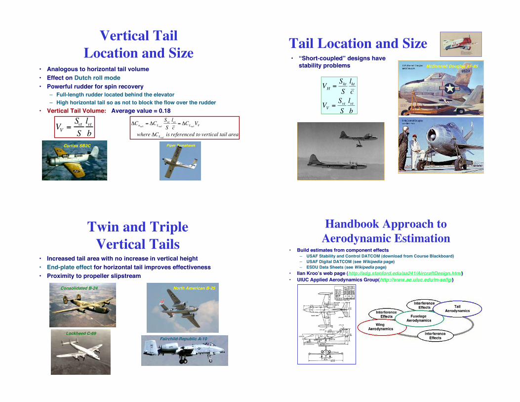
• Analogous to horizontal tail volume
• Effect on Dutch roll mode
• Powerful rudder for spin recovery
– Full-length rudder located behind the elevator
– High horizontal tail so as not to block the flow over the rudder
• Vertical Tail Volume: Average value = 0.18
VV=Svt
S
lvt
b
Vertical Tail
Location and Size
!
"Cntail= "CLtail
Svt
S
lvt
c = "CLtail
VV
where "CLtailis referenced to vertical tail area
Curtiss SB2C Piper Tomahawk
Tail Location and Size
!
VH
=S
ht
S
lht
c
VV
=S
vt
S
lvt
b
McDonnell Douglas XF-85
• “Short-coupled” designs havestability problems
• Increased tail area with no increase in vertical height
• End-plate effect for horizontal tail improves effectiveness
• Proximity to propeller slipstream
Twin and Triple
Vertical Tails
North American B-25
Lockheed C-69
Consolidated B-24
Fairchild-Republic A-10
Handbook Approach to
Aerodynamic Estimation• Build estimates from component effects
– USAF Stability and Control DATCOM (download from Course Blackboard)
– USAF Digital DATCOM (see Wikipedia page)
– ESDU Data Sheets (see Wikipedia page)
• Ilan Kroo!s web page (http://adg.stanford.edu/aa241/AircraftDesign.html)
• UIUC Applied Aerodynamics Group(http://www.ae.uiuc.edu/m-selig/)

• NASA 30! x 60! Tunnel
– Full-scale aircraft on balance
– Sub-scale aircraft on sting
– Sub-scale aircraft in free flight
– Maximum airspeed = 118 mph
– Constructed in 1931 for $37M(~$500M in today!s dollars)
– Two 4000-hp electric motors
Wind Tunnel Data
Tested virtually every USairplane used in World War II,when it was operating 24/7
Interpreting Wind Tunnel Data
• Wall corrections, uniformity of theflow, turbulence, flow recirculation,temperature, external winds (opencircuit)
• Open-throat tunnel equilibratespressure
• Tunnel mounts and balances: struts,wires, stings, magnetic support
• Simulating power effects, flow-through effects, aeroelasticdeformation, surface distortions
• Artifices to improve reduced/full-scale correlation, e.g., boundary layertrips and vortex generators
Computational Fluid Dynamics
• Strip theory– Sum or integrate 2-D airfoil force
and moment estimates over wingand tail spans
• 3-D calculations at grid points– Finite-element or finite-difference
modeling
– Pressures and flow velocities (orvorticity) at points or over panels ofaircraft surface
– Euler equations neglect viscosity
– Navier-Stokes equations do not
Design for Control
• Elevator/stabilator: pitch control
• Rudder: yaw control
• Ailerons: roll control
• Trailing-edge flaps: low-angle lift control
• Leading-edge flaps: High-angle lift control
• Spoilers: Roll, lift, and drag control
• Thrust: speed/altitude control
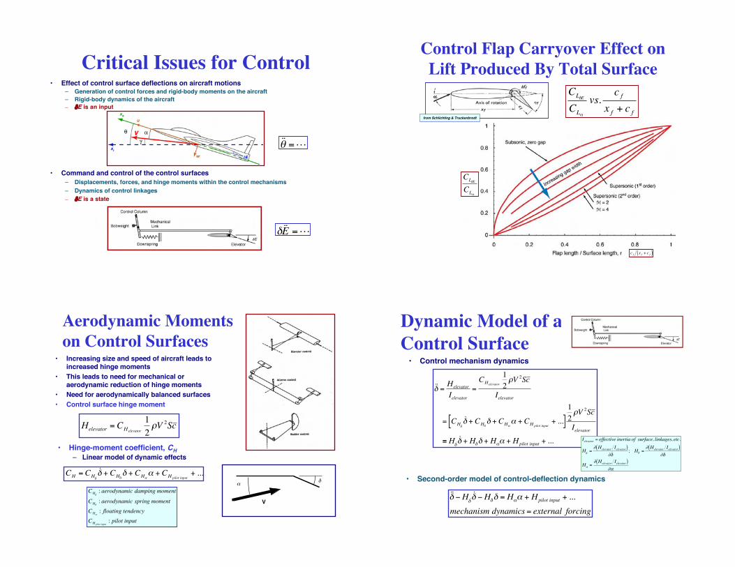
Critical Issues for Control• Effect of control surface deflections on aircraft motions
– Generation of control forces and rigid-body moments on the aircraft
– Rigid-body dynamics of the aircraft
– "E is an input
• Command and control of the control surfaces
– Displacements, forces, and hinge moments within the control mechanisms
– Dynamics of control linkages
– "E is a state
!
˙ ̇ " =L
!
" ˙ ̇ E =L
Control Flap Carryover Effect on
Lift Produced By Total Surface
from Schlichting & Truckenbrodt
!
CL"E
CL#
vs.c f
x f + c f
!
CL"E
CL#
!
c f x f + c f( )
Aerodynamic Moments
on Control Surfaces• Increasing size and speed of aircraft leads to
increased hinge moments
• This leads to need for mechanical oraerodynamic reduction of hinge moments
• Need for aerodynamically balanced surfaces
• Control surface hinge moment
!
Helevator
= CHelevator
1
2"V
2Sc
!
V
"
!
CH = CH ˙ "
˙ " + CH"" + CH#
# + CHpilot input+ ...
!
CH ˙ " : aerodynamic damping moment
CH": aerodynamic spring moment
CH#: floating tendency
CHpilot input: pilot input
• Hinge-moment coefficient, CH
– Linear model of dynamic effects
Dynamic Model of a
Control Surface
!
˙ ̇ " =Helevator
Ielevator
=CHelevator
1
2#V
2Sc
Ielevator
= CH ˙ "
˙ " + CH"" + CH$
$ + CH pilot input+ ...[ ]
1
2#V
2Sc
Ielevator
% H ˙ " ˙ " + H"" + H$$ + Hpilot input + ...
!
˙ ̇ " #H ˙ " ˙ " #H"" = H$$ + Hpilot input + ...
mechanism dynamics = external forcing
!
Ielevator = effective inertia of surface, linkages, etc.
H ˙ " =# Helevator Ielevator( )
# ˙ " ; H" =
# Helevator Ielevator( )#"
H$ =# Helevator Ielevator( )
#$
• Second-order model of control-deflection dynamics
• Control mechanism dynamics

Horn Balance
• Inertial and aerodynamic effects
• Control surface in front of hinge line
– Increasing improves pitch stability,to a point
• Too much area
– Degrades restoring moment
– Increases possibility of mechanicalinstability
– Increases possibility of destabilizingcoupling to short-period mode
!
CH " CH## + CH$
$ + CHpilot input
• Stick-free case– Control surface free to “float”
!
CH" C
H## + C
H$$
• Normally
!
CH"< 0 : reduces short # period stability
CH$< 0 : required for mechanical stability
!
CH"
Overhang or
Leading-Edge
Balance• Effect is similar to
that of horn balance
• Varying gap andprotrusion intoairstream withdeflection angle
!
CH " CH## + CH$
$ + CHpilot input
Trailing-Edge
Bevel Balance
• See discussion inAbzug and Larrabee
!
CH " CH## + CH$
$ + CHpilot input
Internally Balanced
Control Surface
• B-52 application– Control-surface fin
with flexible sealmoves within aninternal cavity in themain surface
– Differentialpressures reducecontrol hingemoment
!
CH " CH## + CH$
$ + CHpilot input

All-Moving Control Surfaces
• Particularly effective at supersonic speed (BoeingBomarc wing tips, North American X-15 horizontaland vertical tails, Grumman F-14 horizontal tail)
• SB.4!s “aero-isoclinic” wing
• Sometimes used for trim only (e.g., Lockheed L-1011horizontal tail)
• Hinge moment variations with flight condition
Shorts SB.4
Bomarc
X-15
F-14
L-1011
Aft Flap vs. All-Moving
Control Surface
• Carryover effect
– Aft-flap deflection can be almost as effective asfull surface deflection at subsonic speeds
– Negligible at supersonic speed
• Aft flap
– Mass and inertia lower, reducing likelihood ofmechanical instability
– Aerodynamic hinge moment is lower
– Can be mounted on structurally rigid mainsurface
Ailerons• When one aileron goes up, the
other goes down
– Average hinge moment affectsstick force
• Frise aileron
– Asymmetric contour, with hingeline at or below loweraerodynamic surface
– Reduces hinge moment
• Cross-coupling effects can beadverse or favorable, e.g. yawrate with roll
– Up travel of one > down travel ofother to control yaw effect
Spoilers• Spoiler reduces lift, increases drag
– Speed control
• Differential spoilers– Roll control
– Avoid twist produced by outboardailerons on long, slender wings
– free trailing edge for larger high-liftflaps
• Plug-slot spoiler on P-61 BlackWidow: low control force
• Hinged flap has high hinge moment
North American P-61

Rudder• Rudder provides yaw control
– Turn coordination
– Countering adverse yaw
– Crosswind correction
– Countering yaw due to engine loss
• Strong rolling effect, particularly at high !
• Only control surface whose nominalaerodynamic angle is zero
• Possible nonlinear effect at low deflectionangle
• Insensitivity at high supersonic speed– Wedge shape, all-moving surface on X-15
Martin B-57
Bell X-2
Control Tabs• Balancing or geared tabs
– Tab is linked to the main surface inopposition to control motion, reducingthe hinge moment with little change incontrol effect
• Flying tabs– Pilot's controls affect only the tab,
whose hinge moment moves thecontrol surface [BAC 1-11 deep stallflight test accident]
• Linked tabs– divide pilot's input between tab and
main surface
• Spring tabs– put a spring in the link to the main
surface
BAC 1-11
Control Mechanization Effects
• Fabric-covered control surfaces (e.g., DC-3, Spitfire)subject to distortion under air loads, changing stabilityand control characteristics
• Control cable stretching
• Elasticity of the airframe changes cable/pushrodgeometry
• Nonlinear control effects– friction
– breakout forces
– backlash
Instabilities Due To
Control Mechanization• Aileron buzz (aero-mechanical instability; P-80 test, Avro CF-105)
• Rudder snaking (Dutch roll/mechanical coupling; Meteor, He-162, X-1)
• Aeroelastic coupling (B-47, Boeing 707 yaw dampers)

Downsprings and Bobweights• Downspring
– Long mechanical spring withlow spring constant
– Exerts a trailing-edge downmoment on the elevator
• Bobweight
– Weight on control column thataffects feel or basic stability
– Mechanical stabilityaugmentation
Beechcraft B-18
Mechanical and Augmented
Control Systems• Mechanical system
– Push rods, bellcranks, cables, pulleys
– On almost all aircraft currently flying
• Power boost– Pilot's input augmented by hydraulic servo that
lowers manual force
• Fully powered (irreversible) system– No direct mechanical path from pilot to
controls
– Mechanical linkages from cockpit controls toservo actuators
Mechanical, Power-Boosted Systems
McDonnell Douglas F-15
Grumman A-6
Advanced Control Systems
• Artificial-feel systems
– Restores the pilot's controlforces to those of an "honest"airplane
– "q-feel" modifies force gradient
– Variation with trim stabilizerangle
– Bobweight responds to gravityand to normal acceleration
• Fly-by-wire/light systems
– Minimal mechanical runsthrough the airplane
– Command input and feedbacksignals drive servo actuators
– Fully powered systems
– Move toward electric rather thanhydraulic power

Boeing 767 Elevator Control System Boeing 777 Fly-By-Wire Control System
Control-Configured Vehicles
• Command/stability augmentation
• Lateral-directional response
– Bank without turn
– Turn without bank
– Yaw without lateral translation
– Lateral translation without yaw
– Velocity-axis roll (i.e., bank)
• Longitudinal response
– Pitch without heave
– Heave without pitch
– Normal load factor
– Pitch-command/attitude-hold
– Flight path angle
USAF F-15 IFCS
Princeton Variable-Response Research AircraftUSAF AFTI/F-16
Power Effects on Stability and Control
• Gee Bee R1 Racer: an enginewith wings and almost no tail
• During W.W.II, the size offighters remained about thesame, but installed horsepowerdoubled (F4F vs. F8F)
• Use of flaps means high powerat low speed, increasingrelative significance of thrusteffects (AD)
Douglas AD-1 Grumman F8F
Grumman F4F
GB R1

Multi-Engine Aircraft of World War II
• Large W.W.II aircraft (e.g., B-17,B-24, and B-29) had unpoweredcontrols:
– High foot-pedal force
– Rudder stability problemsarising from balancing to reducepedal force
• Severe engine-out problem fortwin-engine aircraft, e.g., A-26,B-25, and B-26
Loss of Engine• Loss of engine produces large yawing
(and sometimes rolling) moment(s),requiring major application of controls
• Engine-out training can be ashazardous, especially during takeoff, forboth propeller and jet aircraft
• Acute problem for general-aviationpilots graduating from single-engineaircraft
Solutions to the
Engine-Out Problem
• Engines on the centerline (Cessna337 Skymaster)
• More engines (B-36)
• Cross-shafting of engines (V-22)
• Large vertical tail (Boeing 737)
NASA TCV (Boeing 737)
Cessna 337
Convair B-36
Boeing/Bell V-22
Direct Thrust Effect
on Speed Stability• In powered, steady, level flight, nominal thrust balances
nominal drag
!T
!V=
< 0, for propeller aircraft
" 0, for turbojet aircraft
> 0, for ramjet aircraft
#
$ %
& %
!
"D
"V> 0 for most flight regimes
!T
!V"!D
!V> 0
!
TN"D
N= C
TN
1
2#V
N
2
S "CDN
1
2#V
N
2
S = 0
• Effect of velocity change
• Small velocity perturbation grows if
• Therefore, propeller is stabilizing for velocity change,turbojet has neutral effect, and ramjet is destabilizing

Pitching Moment Due to Thrust• Thrust line above or below center of mass induces a pitching moment
• XB-51, PBY, MD-11, A-10
Martin XB-51
McDonnell Douglas MD-11
Consolidated PBY
Fairchild-Republic A-10
Velocity-Dependent Thrust-
Induced Pitching Moment
• Negative "M/"V (Pitch-down effect) tends to increase velocity
• Positive "M/"V (Pitch-up effect) tends to decrease velocity
• With propeller thrust line above the c.m., increased velocity decreasesthrust, producing a pitch-up moment
• Tilting the propeller thrust line can have benefits (Lake Amphibian, F6FHellcat, F8F Bearcat, and AD Skyraider)
!
"Mthrust
"V#"T
"V$Moment Arm
Douglas AD-1
Lake Amphibian
Grumman F6F
Grumman F8F
Propeller Effects
• Slipstream washing over wing, tail,and fuselage
– Increased dynamic pressure
– Swirl of flow
– Downwash and sidewash at the tail
• DH-2 unstable with engine out
• Difference between single- andmulti-engine effects
• Design factors: fin offset (correct atone airspeed only), c.m. offset
• Propeller fin effect: Visualizelateral/horizontal projections of thepropeller as forward surfaces
• Counter-rotating propellers tominimize torque and swirl
Westland Wyvern
DeHavilland DH-2
Jet Effects on Rigid-Body Motion• Normal force at intake (analogous to propeller fin effect) (F-86)
• Deflection of airflow past tail due to entrainment in exhaust (F/A-18)
• Pitch and yaw damping due to internal exhaust flow
• Angular momentum of rotating machinery
North American F-86
McDonnell Douglas F/A-18

United Flight 232, DC-10, Sioux City, IA, 1989
• Uncontained engine failure damaged allthree flight control hydraulic systems(http://en.wikipedia.org/wiki/United_Airlines_Flight_232)
• Crew resource management(http://en.wikipedia.org/wiki/Crew_Resource_Management)
• 296 people onboard
• 185 survived due to pilot!s differentialcontrol of engines
Propulsion Controlled Aircraft• Proposed backup attitude control in event of flight control system failure
• Differential throttling of engines to produce control moments
• Requires feedback control for satisfactory flying qualities
NASA MD-11 PCA Flight Test
NASA F-15 PCA Flight Test
• Proposed retrofit to McDonnell-Douglas (Boeing) C-17
Next Time:Linearized Equations and
Modes of Motion