Embed Size (px)
Citation preview

RVLAIR-WATER CHILLERS AND HEAT PUMPS
WITH AXIAL FANS
TECHNICAL MANUAL

2
3
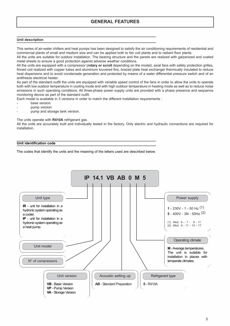
TABLE OF CONTENTS
GENERAL FEATURES . . . . . . . . . . . . . . . . . . . . . . . . . . . . . . . . . . . . . . . . . . . . . . . . . . . . . . . . . . . . . . . . . . . . . . . . . . . . . . . .5UNIT DESCRIPTION . . . . . . . . . . . . . . . . . . . . . . . . . . . . . . . . . . . . . . . . . . . . . . . . . . . . . . . . . . . . . . . . . . . . . . . . . . . . . . .5
UNIT IDENTIFICATION CODE . . . . . . . . . . . . . . . . . . . . . . . . . . . . . . . . . . . . . . . . . . . . . . . . . . . . . . . . . . . . . . . . . . . . . . .5
DESCRIPTION OF PARTS . . . . . . . . . . . . . . . . . . . . . . . . . . . . . . . . . . . . . . . . . . . . . . . . . . . . . . . . . . . . . . . . . . . . . . . . . .6
VERSIONS . . . . . . . . . . . . . . . . . . . . . . . . . . . . . . . . . . . . . . . . . . . . . . . . . . . . . . . . . . . . . . . . . . . . . . . . . . . . . . . . . . . . . . .7
ACCESSORIES . . . . . . . . . . . . . . . . . . . . . . . . . . . . . . . . . . . . . . . . . . . . . . . . . . . . . . . . . . . . . . . . . . . . . . . . . . . . . . . . . . .8
TECHNICAL DATA AND PERFORMANCE . . . . . . . . . . . . . . . . . . . . . . . . . . . . . . . . . . . . . . . . . . . . . . . . . . . . . . . . . . . . . . . .9TECHNICAL DATA . . . . . . . . . . . . . . . . . . . . . . . . . . . . . . . . . . . . . . . . . . . . . . . . . . . . . . . . . . . . . . . . . . . . . . . . . . . . . . . . .9
NOMINAL PERFORMANCE IR . . . . . . . . . . . . . . . . . . . . . . . . . . . . . . . . . . . . . . . . . . . . . . . . . . . . . . . . . . . . . . . . . . . . . .10
NOMINAL PERFORMANCE IP . . . . . . . . . . . . . . . . . . . . . . . . . . . . . . . . . . . . . . . . . . . . . . . . . . . . . . . . . . . . . . . . . . . . . .10
PERFORMANCE IN COOLING (IR AND IP) . . . . . . . . . . . . . . . . . . . . . . . . . . . . . . . . . . . . . . . . . . . . . . . . . . . . . . . . . . . .11
PERFORMANCE IN HEATING (IP) . . . . . . . . . . . . . . . . . . . . . . . . . . . . . . . . . . . . . . . . . . . . . . . . . . . . . . . . . . . . . . . . . . .12
WEIGHTS OF UNITS . . . . . . . . . . . . . . . . . . . . . . . . . . . . . . . . . . . . . . . . . . . . . . . . . . . . . . . . . . . . . . . . . . . . . . . . . . . . . .13
ELECTRICAL DATA . . . . . . . . . . . . . . . . . . . . . . . . . . . . . . . . . . . . . . . . . . . . . . . . . . . . . . . . . . . . . . . . . . . . . . . . . . . . . . .13
NOISE LEVELS . . . . . . . . . . . . . . . . . . . . . . . . . . . . . . . . . . . . . . . . . . . . . . . . . . . . . . . . . . . . . . . . . . . . . . . . . . . . . . . . . .13
PRESSURE LOSSES (VERSION VB) . . . . . . . . . . . . . . . . . . . . . . . . . . . . . . . . . . . . . . . . . . . . . . . . . . . . . . . . . . . . . . . . .14
USEFUL HEAD (VERSION VP AND VA) . . . . . . . . . . . . . . . . . . . . . . . . . . . . . . . . . . . . . . . . . . . . . . . . . . . . . . . . . . . . . . .14
OPERATION LIMITS . . . . . . . . . . . . . . . . . . . . . . . . . . . . . . . . . . . . . . . . . . . . . . . . . . . . . . . . . . . . . . . . . . . . . . . . . . . . . . .15
DIMENSIONS . . . . . . . . . . . . . . . . . . . . . . . . . . . . . . . . . . . . . . . . . . . . . . . . . . . . . . . . . . . . . . . . . . . . . . . . . . . . . . . . . . . .16
CONNECTIONS . . . . . . . . . . . . . . . . . . . . . . . . . . . . . . . . . . . . . . . . . . . . . . . . . . . . . . . . . . . . . . . . . . . . . . . . . . . . . . . . . . . . .17PLUMBING CONNECTIONS . . . . . . . . . . . . . . . . . . . . . . . . . . . . . . . . . . . . . . . . . . . . . . . . . . . . . . . . . . . . . . . . . . . . . . . .17
EXPANSION TANK SETTING . . . . . . . . . . . . . . . . . . . . . . . . . . . . . . . . . . . . . . . . . . . . . . . . . . . . . . . . . . . . . . . . . . . . . . . .18
ELECTRICAL CONNECTIONS . . . . . . . . . . . . . . . . . . . . . . . . . . . . . . . . . . . . . . . . . . . . . . . . . . . . . . . . . . . . . . . . . . . . . . .19

4
5
GENERAL FEATURES
Unit description
This series of air-water chillers and heat pumps has been designed to satisfy the air conditioning requirements of residential and
commercial plants of small and medium size and can be applied both to fan coil plants and to radiant floor plants.
All the units are suitable for outdoor installation. The bearing structure and the panels are realized with galzanized and coated
metal sheets to ensure a good protection against adverse weather conditions.
All the units are equipped with a compressor (rotary or scroll depending on the model), axial fans with safety protection grilles,
finned coil realized with copper tubes and aluminium louvered fins, brazed plate heat exchanger thermically insulated to reduce
heat dispersions and to avoid condensate generation and protected by means of a water differential pressure switch and of an
antifreeze electrical heater.
As part of the standard outfit the units are equipped with variable speed control of the fans in order to allow the units to operate
both with low outdoor temperature in cooling mode and with high outdoor temperature in heating mode as well as to reduce noise
emissions in such operating conditions. All three-phase power supply units are provided with a phase presence and sequence
monitoring device as part of the standard outfit.
Each model is available in 3 versions in order to match the different installation requirements :
- base version
- pump version
- pump and storage tank version.
The units operate with R410A refrigerant gas.
All the units are accurately built and individually tested in the factory. Only electric and hydraulic connections are required for
installation.
IP 14.1 VB AB 0 M 5
VB - Basic Version
VP - Pump Version
VA - Storage Version
Unit version
(1) : Mod. 6 - 7 - 9 - 11
(2) : Mod. 9 - 11 - 14 - 17
1 - 230V - 1 - 50 Hz (1)
5 - 400V - 3N - 50Hz (2)
Unit identification code
The codes that identify the units and the meaning of the letters used are described below.
AB - Standard Preparation
Acoustic setting up
0 - R410A
Refrigerant type
M - Average temperatures.
The unit is suitable for
installation in places with
temperate climates.
Operating climate
Power supply
IR - unit for installation in a
hydronic system operating as
a cooler.
IP - unit for installation in a
hydronic system operating as
a heat pump.
Unit type
Unit model
N° of compressors
6
GENERAL FEATURES
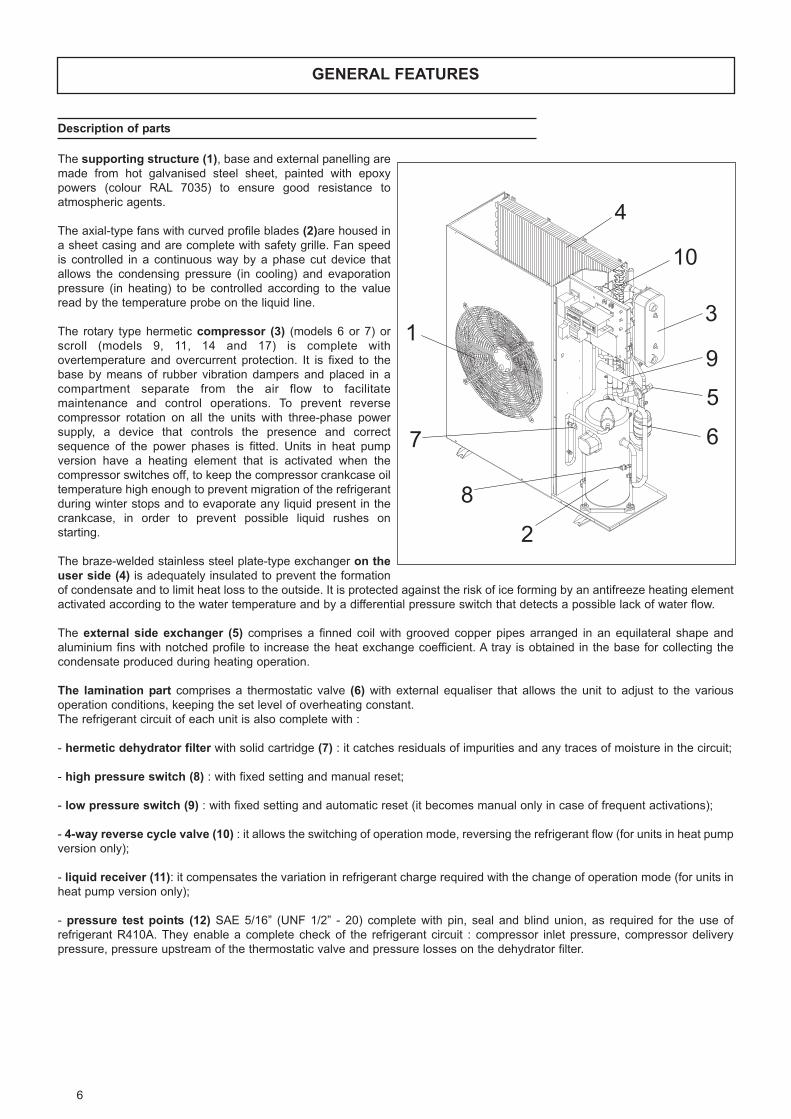
Description of parts
The supporting structure (1), base and external panelling are
made from hot galvanised steel sheet, painted with epoxy
powers (colour RAL 7035) to ensure good resistance to
atmospheric agents.
The axial-type fans with curved profile blades (2)are housed in
a sheet casing and are complete with safety grille. Fan speed
is controlled in a continuous way by a phase cut device that
allows the condensing pressure (in cooling) and evaporation
pressure (in heating) to be controlled according to the value
read by the temperature probe on the liquid line.
The rotary type hermetic compressor (3) (models 6 or 7) or
scroll (models 9, 11, 14 and 17) is complete with
overtemperature and overcurrent protection. It is fixed to the
base by means of rubber vibration dampers and placed in a
compartment separate from the air flow to facilitate
maintenance and control operations. To prevent reverse
compressor rotation on all the units with three-phase power
supply, a device that controls the presence and correct
sequence of the power phases is fitted. Units in heat pump
version have a heating element that is activated when the
compressor switches off, to keep the compressor crankcase oil
temperature high enough to prevent migration of the refrigerant
during winter stops and to evaporate any liquid present in the
crankcase, in order to prevent possible liquid rushes on
starting.
The braze-welded stainless steel plate-type exchanger on theuser side (4) is adequately insulated to prevent the formation
of condensate and to limit heat loss to the outside. It is protected against the risk of ice forming by an antifreeze heating element
activated according to the water temperature and by a differential pressure switch that detects a possible lack of water flow.
The external side exchanger (5) comprises a finned coil with grooved copper pipes arranged in an equilateral shape and
aluminium fins with notched profile to increase the heat exchange coefficient. A tray is obtained in the base for collecting the
condensate produced during heating operation.
The lamination part comprises a thermostatic valve (6) with external equaliser that allows the unit to adjust to the various
operation conditions, keeping the set level of overheating constant.
The refrigerant circuit of each unit is also complete with :
- hermetic dehydrator filter with solid cartridge (7) : it catches residuals of impurities and any traces of moisture in the circuit;
- high pressure switch (8) : with fixed setting and manual reset;
- low pressure switch (9) : with fixed setting and automatic reset (it becomes manual only in case of frequent activations);
- 4-way reverse cycle valve (10) : it allows the switching of operation mode, reversing the refrigerant flow (for units in heat pump
version only);
- liquid receiver (11): it compensates the variation in refrigerant charge required with the change of operation mode (for units in
heat pump version only);
- pressure test points (12) SAE 5/16” (UNF 1/2” - 20) complete with pin, seal and blind union, as required for the use of
refrigerant R410A. They enable a complete check of the refrigerant circuit : compressor inlet pressure, compressor delivery
pressure, pressure upstream of the thermostatic valve and pressure losses on the dehydrator filter.
1
2
3
10
9
5
4
67
8

7
GENERAL FEATURES
Versions
Each model can be supplied in three different versions to meet the application needs of the systems. The unit always comes
assembled, wired and factory-tested.
Basic Version - VB
The unit does not contain a circulating
pump or storage tank. Therefore an
adequate flow of water through the
plate-type exchanger must be
guaranteed to prevent activation of the
internal safety devices. If adequately
sized, the pump can in any case be
connected to the unit’s electrical panel
and managed by the controller.
Pump Version - VP
The unit contains a circulating pump,
metal cartridge filter (to protect the
plate-type exchanger), air vents and
drain cock.
Storage Version - VA
The unit contains a storage tank
(configured as storage on the delivery to
the system), circulating pump, metal
cartridge filter (to protect the plate-type
exchanger), air vents, safety valve,
expansion tank and drain cock.. The
tank is also arranged for fitting
antifreeze or supplementary heating
elements.
The command and control electrical panel incorporated in the
unit contains all the power, adjustment and safety components
necessary to guarantee correct operation. The main switch
and user interface are accessible from the outside by opening
a hermetic door.
The main components are :
- main switch (thermal magnetic)
- microprocessor controller with user interface and
incorporated phase cut card
- compressor contactor
- wiring board with transformer, protection fuses and user
terminal block
- mesh filter
- compressor start condenser (units with single-phase power
supply only)
- start condenser for fans
- device for control of presence and correct power supply
phase sequence (units with three-phase power supply only)
The unit is managed by a microprocessor controller to
which all the loads and control devices are connected by
means of a wiring board. The user interface comprises a
display and 4 buttons for displaying and possibly modifying all
the unit’s operation parameters. A remote keyboard with all the
functions of the interface fitted on the machine is available as
an accessory.
The main functions available are :
- adjustment of treated water temperature (by setting the
setpoint)
- climate control in heating (modification of setpoint according
to the outside air temperature)
- dynamic defrost according to outside air temperature
- display of active alarms and alarms history
- continuous fan speed control
- pump management
- recording of compressor and pump operation hours
- serial communication by Modbus protocol
- remote standby
- remote cooling-heating
- digital output for general alarm

8
GENERAL FEATURES
Accessories
Coil protection grilles - GPIt comprises a painted electrowelded grille that protects the finned coil.
Rubber vibration dampers - AVGThese reduce the transmission to the machine support surface of mechanical vibrations generated by the compressor and fans
during their normal operation. The number of vibration dampers depends on the version. To ensure the efficiency of this
accessory it is advisable to use vibration-damping joints on the plumbing connections.
Tank antifreeze heating element - RAGActivated together with the plate-type exchanger antifreeze heating element, its purpose is to keep the water in the storage tank
at a suitable temperature to prevent ice forming during winter idle periods.
Supplementary heating elements - RELThey supplement or substitute the heating power supplied by the heat pump and are managed by the unit’s controller with two-
step logic. They also substitute the tank antifreeze heating element accessory (RAG).
Remote control - CRThe remote control is suitable for wall mounting and has all the control and display functions available on the unit’s interface. It
therefore enables complete remote control of the unit.
Serial interface - KMBIt enables communication with the unit’s controller and monitoring the operating conditions by means of Modbus communication
protocol. Use of the RS485 serial line ensures the quality of the signal up to distances of approx. 1200 metres (extendable by
means of special repeaters).
Programmer clock - OPIt allows the unit to be turned on and off according to a preset programme by operating on the digital input available on the unit’s
control card (remote on-off).
MODELABBREV. ACCESSORY
Version
VB VP VA
GP Coil protection grilles F F F
AVG Rubber vibration dampers F F F
RAG Tank antifreeze heating element - - F
REL Supplementary heating elements - - M
CR Remote control F F F
KMB Serial interface F F F
OP Programmer clock F F F
M : accessory factory-installedF : accessory supplied (installation to be carried out by the customer)

9
TECHNICAL DATA AND PERFORMANCE
Technical data
Frame 1 2 3
Model 6.1 7.1 9.1 11.1 14.1 17.1 U.M.
Electrical power supply 230-1-50 230-1-50 230-1-50 400-3N-50 230-1-50 400-3N-50 400-3N-50 400-3N-50 V-ph-Hz
Compressor
Type rotativo scroll -
Quantity 1 n°
Capacity steps 0 - 100 %
Oil charge 1,13 1,13 1,20 1,20 1,80 1,80 1,80 1,80 kg
Refrigerant
Type R410A -
Refrigerant
Type axial -
Quantity 1 2 n°
Diameter 450 500 mm
Max. rotation speed 900 rpm
Total installed power 0,15 0,21 0,42 kW
Plate-type heat exchanger
Type braze-welded plates -
Quantity 1 n°
Water content 0,29 0,29 0,46 0,46 0,46 0,46 0,53 0,72 l
Finned coil
Type copper pipes - aluminium fins -
Quantity 1 n°
Front surface 0,60 0,77 0,98 m2
Pump (versions VP and VA)
Type circulating pump multistage centrifugal pump -
Quantity 1 n°
Installed power 0,20 0,75 kW
Storage tank (version VA)
Storage volume 33 50 71 l
Safety valve setting 6 bar
Expansion tank volume 5 l
Tank antifreeze heating element - RAG
Power 0,25 kW
Supplementary heating elements - REL
Power 3,3 3,3 / 6,6 6,6 kW
Capacity steps 2 n°

10
TECHNICAL DATA AND PERFORMANCE
Nominal performance IR
Nominal performance IP
Frame 1 2 3
Model 6.1 7.1 9.1 11.1 14.1 17.1 U.M.
Electrical power supply 230-1-50 230-1-50 400-3N-50 230-1-50 400-3N-50 400-3N-50 V-ph-Hz
Cooling (air 35 °C bs / water 12 - 7 °C )
Refrigerating capacity (E) 6,20 7,40 9,40 9,40 10,8 10,8 13,8 17,3 kW
Total input (VB) (E) 2,15 2,85 3,70 3,70 4,15 4,15 5,15 6,65 kW
total EER (VB) (E) 2,88 2,60 2,54 2,54 2,60 2,60 2,68 2,60 -
Water delivery 1066 1273 1617 1617 1858 1858 2374 2976 l/h
Pressure losses (VB) (E) 28 38 26 26 33 33 40 35 kPa
Useful head (VP-VA) 73 58 170 170 152 152 122 96 kPa
Cooling (air 35 °C bs / water 23 - 18 °C )
Refrigerating capacity 7,40 8,90 11,3 11,3 13,0 13,0 16,6 20,8 kW
Total input (VB) 2,20 2,90 3,80 3,80 4,25 4,25 5,30 6,85 kW
Total EER (VB) 3,36 3,07 2,97 2,97 3,06 3,06 3,13 3,04 -
Water delivery 1273 1531 1944 1944 2236 2236 2855 3578 l/h
Pressure losses (VB) (E) 38 53 36 36 46 46 56 49 kPa
Useful head (VP-VA) 58 37 146 146 122 122 82 49 kPa
ESEER(VB)(E) 3,26 2,94 2,88 2,88 2,94 2,94 3,04 2,94 -
Frame 1 2 3
Model 6.1 7.1 9.1 11.1 14.1 17.1 U.M.
Electrical power supply 230-1-50 230-1-50 230-1-50 400-3N-50 230-1-50 400-3N-50 400-3N-50 400-3N-50 V-ph-Hz
Cooling (air 35 °C bs / water 12 - 7 °C )
Refrigerating capacity (E) 6,00 7,10 9,20 9,20 10,6 10,6 13,6 17,1 kW
Total input (VB) (E) 2,15 2,85 3,70 3,70 4,15 4,15 5,15 6,65 kW
Total EER (VB) (E) 2,79 2,49 2,49 2,49 2,55 2,55 2,64 2,57 -
Water delivery 1032 1221 1582 1582 1823 1823 2339 2941 l/h
Pressure losses (VB) (E) 26 35 25 25 32 32 39 34 kPa
Useful head (VP-VA) 75 62 173 173 155 155 124 99 kPa
Cooling (air 35 °C bs / water 23 - 18 °C )
Refrigerating capacity 7,20 8,50 11,0 11,0 12,8 12,8 16,3 20,5 kW
Total input (VB) 2,20 2,90 3,80 3,80 4,25 4,25 5,30 6,85 kW
Total EER (VB) 3,27 2,93 2,89 2,89 3,01 3,01 3,08 2,99 -
Water delivery 1238 1462 1892 1892 2202 2202 2804 3526 l/h
Pressure losses (VB) (E) 36 49 34 34 45 45 54 48 kPa
Useful head (VP-VA) 60 43 150 150 125 125 86 53 kPa
ESEER(VB)(E) 3,16 2,82 2,82 2,82 2,89 2,89 2,99 2,91 -
Heating (air 7 °C bs - 6 °C bu / water 40 - 45 °C )
Heat output (E) 7,00 8,20 10,4 10,4 11,5 11,5 15,3 18,6 kW
Total input (VB) (E) 2,25 2,75 3,65 3,65 4,05 4,05 4,95 6,40 kW
Total COP (VB) (E) 3,11 2,98 2,85 2,85 2,84 2,84 3,09 2,91 -
Water delivery 1204 1410 1789 1789 1978 1978 2632 3199 l/h
Pressure losses (VB) (E) 34 46 31 31 37 37 48 40 kPa
Useful head (VP-VA) 63 47 157 157 143 143 101 79 kPa
Heating (air 7 °C bs - 6 °C bu / water 30 - 35 °C )
Heat output 7,20 8,40 10,6 10,6 11,7 11,7 15,6 19,0 kW
Total input (VB) 1,90 2,35 3,05 3,05 3,40 3,40 4,15 5,40 kW
Total COP (VB) 3,79 3,57 3,48 3,48 3,44 3,44 3,76 3,52 -
Water delivery 1238 1445 1823 1823 2012 2012 2683 3268 l/h
Pressure losses (VB) (E) 36 48 32 32 38 38 50 42 kPa
Useful head (VP-VA) 60 44 155 155 140 140 97 74 kPa
(VB) : only for base version VB(VP-VA) : only for pump version VP and tank version VA
(E) : data declared according to EUROVENT certification programme

11
TECHNICAL DATA AND PERFORMANCE
Performance in cooling (IR and IP)
0,60
0,70
0,80
0,90
1,00
1,10
1,20
1,30
1,40
15 20 25 30 35 40 45
Tbs [°C]
0,50
0,60
0,70
0,80
0,90
1,00
1,10
1,20
1,30
1,40
1,50
1,60
1,70
1,80
15 20 25 30 35 40 45
Tbs [°C]
Refrigerating capacity
Power input EER
0,50
0,60
0,70
0,80
0,90
1,00
1,10
1,20
1,30
15 20 25 30 35 40 45
Tbs [°C]
C
B
A C
B
A
C
B
A
Temperature of water produced:
A = 10°C
B = 7°C
C = 4°C
The graphs provided above can be used to obtain the correction coefficients to be applied to the nominal performance values (air
35°C bs / air 12-7°C) for obtaining the real performance values in the chosen operating conditions.

TECHNICAL DATA AND PERFORMANCE
Performance in heating (IP)
Temperature of water produced:
A = 55°C
B = 50°C
C = 45°C
D = 40°C
E = 35°C
The graphs given above can be used to obtain the correction coefficients to be applied to the nominal performance values (air 7°C
bs - 6°C bu / water 40-45°C) for obtaining the real performance values in the chosen operating conditions.
0,60
0,70
0,80
0,90
1,00
1,10
1,20
1,30
1,40
-15 -10 -5 0 5 10 15
Tbu [°C]
0,50
0,60
0,70
0,80
0,90
1,00
1,10
1,20
1,30
1,40
1,50
-15 -10 -5 0 5 10 15
Tbu [°C]
Power input COP
0,50
0,60
0,70
0,80
0,90
1,00
1,10
1,20
1,30
-15 -10 -5 0 5 10 15
Tbu [°C]
A
C
D
E
B
Heat output
A
C
DE
BA
CD
E
B

13
TECHNICAL DATA AND PERFORMANCE
Electrical data
Noise levels
Weights of units
Frame ModelWeight of unit [kg] Transport weight [kg]
VB VP VA VB VP VA
IR
16.1 86.5 94.5 114.0 92.0 100.0 123.0
7.1 92.5 100.5 120.0 98.0 106.0 129.0
29.1 104.5 118.5 147.0 110.0 124.0 156.0
11.1 122.5 136.5 165.0 128.0 142.0 174.0
314.1 138.0 152.0 188.5 143.5 157.5 197.5
17.1 147.0 161.0 197.5 152.5 166.5 206.5
IP
16.1 88.0 96.0 115.5 93.5 101.5 124.5
7.1 94.5 102.5 122.0 100.0 108.0 131.0
29.1 107.0 121.0 149.5 112.5 126.5 158.5
11.1 125.0 139.0 167.5 130.5 144.5 176.5
314.1 140.5 154.5 191.0 146.0 160.0 200.0
17.1 150.0 164.0 200.5 155.5 169.5 209.5
Frame 1 2 3
Model 6.1 7.1 9.1 11.1 14.1 17.1 U.M.
Power supply 230-1-50 230-1-50 230-1-50 400-3N-50 230-1-50 400-3N-50 400-3N-50 400-3N-50 V-ph-Hz
Version VB *
F.L.A. - Total max. absorbed current 12.9 16.1 22.8 9.1 27.0 10.7 14.2 17.1 A
F.L.I. - Total max. power input 2.8 3.5 4.9 4.9 5.8 5.8 7.5 9.2 kW
M.I.C. - Total max. peak current 49.8 68.8 89.1 48.1 121.1 51.1 67.1 70.1 A
Version VP and VA *
F.L.A. - Total max. absorbed current 14.1 17.3 26.7 13.0 30.9 14.6 18.1 21.0 A
F.L.I. - Total max. power input 3.1 3.8 5.8 5.8 6.7 6.7 8.4 10.1 kW
M.I.C. - Total max. peak current 49.8 68.8 89.1 48.1 121.1 51.1 67.1 70.1 A
Supplementary electrical heating elements : 3,3 kW
F.L.A. - Total max. absorbed current 14,3 14,3 14,3 4,8 14,3 4,8 - - A
F.L.I. - Total max. power input 3,3 3,3 3,3 3,3 3,3 3,3 - - kW
Supplementary electrical heating elements : 6,6 kW
F.L.A. - Total max. absorbed current - - 28,7 9,5 28,7 9,5 9,5 9,5 A
F.L.I. - Total max. power input - - 6,6 6,6 6,6 6,6 6,6 6,6 kW
Model
Sound power levels [dB] for octave bands [Hz]
Sound power level
Sound pressurelevel at 1 m
63 125 250 500 1000 2000 4000 8000 [dB] [dB(A)] [dB(A)]
6.1 74.6 72.5 70.8 67.1 63.6 59.4 53.7 46.2 78 69 55
7.1 74.6 72.5 70.8 67.1 63.6 59.4 53.7 46.2 78 69 55
9.1 77.4 75.3 73.6 69.9 66.4 62.2 56.5 49.0 81 72 57
11.1 77.4 75.3 73.6 69.9 66.4 62.2 56.5 49.0 81 72 57
14.1 79.5 77.4 75.7 72.0 68.5 64.3 58.6 51.1 83 74 59
17.1 79.5 77.4 75.7 72.0 68.5 64.3 58.6 51.1 83 74 59
* Possible accessories excluded.
Reference conditionsPerformance values for standard version (VB) operating in cooling mode in NOMINAL conditions.
Unit positioned in free field on a reflecting surface (directivity factor equal to 2).
The sound power level is measured according to Standard ISO 3744.
The sound pressure level is calculated according to ISO 3744 (Eurovent 8/1) and refers to a distance of 1 metre from the external surface of the unit.

14
TECHNICAL DATA AND PERFORMANCE
0
10
20
30
40
50
60
70
80
0 500 1000 1500 2000 2500 3000 3500 4000
Portata [l/h]
Per
dit
e d
i car
ico
[kP
a]
0
20
40
60
80
100
120
140
160
180
200
220
240
260
0 500 1000 1500 2000 2500 3000 3500 4000
Portata [l/h]
Pre
vale
nza
res
idu
a [k
Pa]
Pressure losses (version VB)
Useful head (version VP and VA)
7.1
6.1
6.1
7.1 9.1
11.1
14.1
17.1
9.1
11.1 17.1
14.1

15
TECHNICAL DATA AND PERFORMANCE
Operation limits
The graphs provided below give the range within which correct operation of the unit is guaranteed. Use in different conditions
from that indicated involves cancellation of the product warranty contract.
Thermal head of water treated by the unit
Minimum 3 °C
Maximum 8 °C
-10
-5
0
5
10
15
20
25
30
35
-5 0 5 10 15 20 25 30 35 40 45 50 55
Tbs aria esterna [°C]
T a
cqu
a p
rod
ott
a [°
C]
15
20
25
30
35
40
45
50
55
60
-20 -15 -10 -5 0 5 10 15 20 25 30 35 40
Tbu aria esterna [°C]
T a
cqu
a p
rod
ott
a [°
C]
IN HEATING
IN COOLING
Tbs outside air [°C]
Tbu outside air [°C]
T w
ate
r pro
duced [
°C]
T w
ate
r pro
duced
[°C
]

TECHNICAL DATA AND PERFORMANCE
IN
OUT
368
394
356
97
52
60
994
A
E
B
C2
D
710 179102
Dimensions
OUT
IN
994
A
710 179102
356
9752
394
368
B60
C1
DBasic Version - VB Pump Version - VP
Storage Version - VA
IN
OUT
368
394
356
710102 58236 220
C3
B60
1329
A
180
17852
E
Frame 1 2 3
U.M.Model 6.1 - 7.1 9.1 - 11.1 14.1 - 17.1
Version VB VP VA VB VP VA VB VP VA
A 903 1153 1453 mm
B 509 759 1059 mm
C1 570 820 1120 mm
C2 545 646 946 mm
C3 799 928 1228 mm
D 839 1089 1389 mm
E 142 97 97 mm
F 400 mm
G 600 mm
H 200 mm
IN 1 1 1 1 1 1 1 1 1 inch
OUT 1 1 1 1 1 1 1 1 1 inch
G
H
F
Minimum operating space
Respect the clearances around the unit indicated in the
figure, to ensure adequate air circulation and to facilitate
maintenance and control operations.
16

17
CONNECTIONS
Plumbing connections
For correct design of the plumbing system comply with the current local safety regulations.
Always ensure an adequate flow of water through the unit’s plate-type exchanger, even if a differential pressure switch
(connected between the exchanger inlet and outlet) that stops the unit in case of insufficient water flows, thus preventing the risk
of freezing, is fitted standard. For that purpose, an antifreeze heating element is also fitted on the plate-type exchanger of all the
units.
To adjust the water flow through the exchanger it is advisable to install a cock at the outlet of the unit.
Basic version (VB) units must be fitted with a mesh filter (Ø holes ≥ 500 µm) at the plate-type exchanger inlet to catch
any foreign substances; the warranty is cancelled if this filter is not fitted.
The plumbing circuit must be kept under pressure using an expansion tank in combination with a safety valve (these parts are
already present in the storage version - VA). A filling unit that automatically fills the system and maintains the required pressure
can be used.
Precautions during the winter periodIn case of a system stop during the winter period, the water could freeze and damage the unit’s exchanger and other parts of
the system. To prevent these problems, three solutions are possible:
1. Completely drain the system, paying attention to emptying the plate-type exchanger (open the air vents to facilitate the
operation).
2. Use water with glycol remembering that, according to the quantity of glycols used, the unit’s performance must be adjusted
by means of correction factors for the refrigerating capacity, input, water delivery and pressure losses.
3. Keep the unit electrically connected throughout the winter. The plate-type exchanger is protected by the antifreeze heating
element fitted standard. The circulating pump is activated by the unit’s controller according to the outside air temperature,
to protect the pipes. Units in storage version (VA) are supplied with an antifreeze heating element, as an accessory to
prevent ice forming inside the tank, activated by the unit’s controller together with the antifreeze heating element of the
plate-type exchanger. The supplementary heating elements, if present, also carry out the antifreeze function.
Suggestions for the plumbing systemPrepare the pipes with the least possible number of bends to minimise pressure losses, and suitably support them to prevent
excessive stresses at the unit’s connections.
Install shut-off valves near the parts subject to maintenance, to allow their replacement without having to drain the system.
Provide for manual or automatic valves in the highest part of the circuit to vent the air.
Make sure there are no leaks before insulating the pipes and filling the system.
Insulate all the refrigerated water pipes to prevent the formation of condensate, using steam barrier type material (otherwise
cover the insulation with appropriate protection). Also make sure the air vent valves are always accessible.
Arrange adequate connections for reading the pressure and temperature at the inlet and outlet of the unit, for possible control of
correct system operation.
Coil condensate drainThe condensate produced by the coil during heating operation is collected in the tray obtained in the base of the unit and can be
drained by connecting a tube to the union supplied standard on all units in heat pump version.

18
CONNECTIONS
Expansion tank setting
All the storage version units (VA) come complete with expansion tank and safety valve. The expansion tank prefilling pressure
must be adequate for the total volume of the plumbing system to which the unit is connected.
The factory setting (pVE = 2 bar g) corresponds to the minimum value necessary for avoiding negative pressure zones inside the
water circuit and the risk of pump cavitation, in the event no users are located above the level on which the unit is installed. In
this case the prefilling pressure must be increased according to the level of the highest user according to the following
relationship :
pVE : expansion tank prefilling pressure [bar g]
Hmax : height difference between the highest user and the unit installation level [m]
When the prefilling pressure increases the maximum volume of the system supported by the expansion tank supplied standard
decreases. If the actual volume of the system is greater than that maximum value, an additional expansion tank of adequate
capacity must be installed.
For units operating with water and glycols calculate the maximum value, applying the correction factors given in the following
table to values obtained from the graph.
The maximum expansion tank prefilling pressure corresponds to the safety valve setting value (6 bar g).
After the water circuit is filled, the pressure at the expansion tank must not be higher than the prefilling pressure.
In case of users located at levels below that on which the unit is installed, make sure the user can take the maximum pressure
generated.
glycol % Ethylene glycols Propylene glycols
10% 20% 30% 40% 10% 20% 30% 40%
IR (10-40°C) 0.738 0.693 0.652 0.615 0.700 0.608 0.543 0.494
IP (10-60°C) 0.855 0.811 0.769 0.731 0.814 0.718 0.647 0.593

19
CONNECTIONS
Electrical connections
The electrical wiring must be carried out by qualified personnel in conformity with the current regulations in the country of use at
the time of installation. Before carrying out any work on the electrical system make sure the unit’s power supply line is
disconnected at the start.
N.B. Refer to the wiring diagram attached to the unit.
Connection to the power supplyThe units come completely factory-wired and arranged for connection to the mains.
The power cables of the unit’s supply line must be taken :
- for units with single-phase power supply : from a single-phase voltage system provided with neutral wire and separate
earth wire;
V = 230 V ± 10 %f = 50 Hz
- for units with three-phase power supply : from a symmetrical three-phase voltage system provided with neutral wire and
separate earth wire.
V = 400 V ± 10 %f = 50 Hz
The power cables must enter the unit through the holes provided in the side panel and be connected to the unit’s main switch.
The earth wire coming from the power supply line must be connected directly to the plate on the electrical panel to ensure the
equipotential connections of all the metal earths and the structural parts of the unit. The cables must be integrally fixed to the
unit’s structure using the special cable clamp on the electrical panel.
IMPORTANTThe power cables must have a section adequate for the power absorbed by the unit and be sized in conformity with the current
regulations. For sizing of the power supply line, always refer to the unit’s total FLI and FLA values, taking into account any
accessories fitted.
Protection upstreamAn automatic switch suitable for ensuring protection against overcurrents and indirect contacts must be installed upstream.
Coordination between the line and switch must be carried out in compliance with the current regulations on electrical safety,
regarding the type of installation and the installation ambient conditions.
Connections to be made by the userThe wiring board inside the electrical panel contains dedicated terminals for the following connections.
General alarm
Live output (230V - max 2A) to be used for signalling the presence of an active alarm.
Output active : alarms present
Output not active : alarms absent
Remote standby
A remote device for turning the unit On/Off (selector, programmer clock, centralised supervision device, etc.) with a voltage-free
contact suitable for switching loads of very low power can be connected.
This function must be enabled by means of parameter (see the section “Adjustment and control”) and has priority over settings
made from keyboard.
Remote cooling-heating
It is possible to switch between cooling mode and heating mode from remote by connecting a device equipped with a voltage-
free contact suitable for switching loads of very low power.
This function must be enabled by means of parameter (see the section “Adjustment and control”) and has priority over settings
made from keyboard.
Remote control
It is possible to connect a remote control that has all the control and display functions available on the unit’s interface and
therefore enable complete remote control.
Pump control
The unit’s controller can directly activate the circulating pump by means of a voltage-free contact (max. absorption 4A).
The manufacturer declines all responsibility for any inaccuracies in this manual due to printing or typing errors.

Co
d.
3Q
E2
36
50


![AS AN INDICATION OF IMPORTANT SAFETY R-410A HEAT PUMP ...€¦ · R-410A HEAT PUMP OUTDOOR UNITS 92-105074-13-01 (10/18)Printed in USA [ ] indicates metric conversions. Do not destroy](https://img.dokumen.tips/doc/110x75/5f459c518d82b60b39713c75/as-an-indication-of-important-safety-r-410a-heat-pump-r-410a-heat-pump-outdoor.jpg)