Embed Size (px)
Citation preview

AIR HANDLING SYSTEMSProduct Catalogue
20
11
AIR
HA
ND
LIN
G U
NIT
S FO
R P
UB
LIC
, C
OM
MER
CIA
L A
ND
IND
UST
RIA
L A
PPLI
CAT
ION
S •
TER
MIN
AL
UN
ITS
• SW
IMM
ING
PO
OL
DEH
UM
IDIF
IER
S.

production sitessubsidiariesdistributors
key
Arquà Polesine (RO) - Italy Lyon - France Barcelona - Spain Baligen - Germany
Arquà Polesine (RO) - Italy Codroipo (UD) - Italy Cluj Napoca - Romania Beijing - China

One of the largest Italian groupsin the heating andair conditioning industry.
Our mission
Improve quality of life in public, residential and tertiary
sector with a highly specialised offer of products and
services for air conditioning, with maximum attention to
customer needs and from the point of view of sustainable
development suited to green building technologies.
Know-how and experience at the service of specialists.
Since 1963, RSAP has been a
leader in the production of
steel tubular radiators. IRSAP
is the pulsating heart of the
group: it combines the heat of
fi re with a burning passion for
well-being.
Since 1968, RHOSS has worked
in the public and industrial air
conditioning sector.
RHOSS is a breath of fresh air
for your body and mind, thanks
to products and systems that
innovate air conditioning.
IR TECH is a company specialised
in radiant cooling and heating
system and renewable sources.
IRTECH designs solid bases for
climate management and is able
to “irradiate“ innovation and
professionalism.
OFFICINA DELLE IDEE line
dedicated to design radiators.
OFFICINA DELLE IDEE
introduces an unmistakable
style to every environment,
giving a form to every desire.

2000
2002
2005OBJECTIVE
“CONTINUOUS IMPROVEMENT“PLAN
FOR ENERGY EFFICIENCY AND FOR THE DESIGN
The approved Research and Development labo-ratory has been created to test the liquid cool-ers and heat pumps ac-cording to the Eurovent "RATING STANDARD FOR LIQUID CHILLING PACK-AGES" (6/C003 - 2010) Standard, which guar-antees and certifi es the requested performance.
EXP has been created, an innova-tive polyvalent heat pump for 2 and 4-pipe applications.
CTA ADVANCEA new range of “Custom” air handling units
Eurovent certifi cation for chilllers, heat pumps and fan coil units.
Introduction of the R134a and R410A range for maximising en-ergy performance.
New EV series fan coil units (Brio EV and Yardy EV), with high per-formance and an exclusive design.
Reengineering of the product range and expansion of the pro-duction lines with the implementation of a testing cabin on each line.

2008
2011
Who is RHOSSRhoss is a company of Irsap group specialised in the design and production of air conditioning
and air handling products and systems. For more than 40 years, Rhoss has been a guarantee for
innovation, quality and top level service. This is what makes us an ideal partner for HVAC system
specialists.
RHOSS's growth and development is an evolution that combines investments and projects
in order to make the company a point of reference also in international markets. Our re-
newal has followed market developments and customer needs, in particular off ering high-
ly effi cient products and systems that are in line with the requirements of the most modern
Green Buildings.
TECHNOLOGICAL INNOVATION FROM THE PRODUCT TO THE SYSTEM
Y-M.I.C.H. has been created, inverter technology used for chillers and heat pumps.
A MODULAR range of air han-dling units with regulation with high service levels.
Two other innovations in-clude Dry-Pool, the fi rst dehumidifi er for pools in R410A, with heat recovery and Yardy HP, a high perform-ance ducted fan coil unit.
Development of innovative so-lutions to maximise comfort and energy saving performance.
We have a permanent research contract with Universities to support innovation.
“Low consumption" technol-ogy for managing R410A chillers and heat pumps, to reduce seasonal energy con-sumption.
From machine certifi cation to system certifi cation in refer-ence to the main air quality and environmental comfort measurement standards.
Heating, cooling and hot water production solutions based on high performance, NF certifi ed heat pumps.
IR TECH, a radiant air conditioning division of Rhoss, off ers an advanced integrated system that maxim-ises comfort, reducing the system's energy require-ments.The innovative system was developed in Rhoss's new R&D Lab, which is able to simulate a building-unit system.


Conscious design for a conscious choice
RHOSS bases its design philosophy on one fundamental concept: testing the behaviour of its
produced machines in all the environmental conditions in which they can be used.
A responsible manufacturer must in fact provide designers with correct data regarding its prod-
ucts under all operating conditions, because each air conditioning unit must deliver a specific
energy performance that can vary based on geography, building features and use requirements.
With its testing rooms, Rhoss's R&D Lab provides its customers with a series of guarantees that
are necessary for a conscious design:
guarantee of performance under the design conditions, which are usually different than
Eurovent nominal conditions;
guarantee of efficiency at full load (EER, COP) or at partial loads (ESEER);
guarantee of continuous operation, especially under the most critical operating conditions:
simply think of severe climates where the ambient air can exceed 50 °C or go down below
–15 °C.
the possibility for the design or end customer to carry out customised tests
Therefore, Rhoss is able to offer products designed for large and small capacity systems, guaran-
teeing that all the components used are integrated together, with a perfect control logic.
This result can only be obtained in laboratories such as Rhoss's R&D Lab, that is, in a complex,
technically advanced structure that most other manufacturers today do not have.


A complete offer for HVAC specialists
Rhoss's off er is targeted towards specialists in the HVAC world.
Rhoss technicians and engineers are constantly engaged in developing air conditioning, heat-
ing and air handling products and systems for applications such as residential, offi ces, hotels and
hospitality structures in general, hospitals, airports and industry.
For each of these applications, Rhoss's solution is targeted towards improving energy effi ciency,
environmental comfort and air handling processes. For this reason, Rhoss products and systems
are divided into four well focused catalogues.
APPLIED SYSTEMSChillers, fan coil units and ter-minal units for public, com-mercial and industrial appli-cations, for small and large systems.
HEAT PUMPSHeat pumps and heating, cooling and hot water pro-duction solutions specifi cally for residential and small serv-ice industry applications.
RADIANT SYSTEMSRadiant air conditioning sys-tems that integrate fl oor, wall and ceiling terminals with chillers/heat pumps, air han-dling units and complete sys-tem regulation. The off ered solutions are specifi c for resi-dential, commercial and large building applications.
AIR HANDLING SYSTEMSAir handling units for public, commercial and industrial uses. Dehumidifi ers for indoor pools.


Sustainable RHOSS technology is recognisable
How to recognisethe Green-Line
In each catalogue, Rhoss off ers solutions that promote sustainable construction in terms of en-
ergy effi ciency, in line with the requirements of modern Green-Buildings. These are products or
systems that were designed with technology that makes it concretely possible to reduce the
energy needs of the HVAC system, but without reducing the comfort in the building where it is
installed.
The Rhoss solutions that excel in sustainability can be easily recognised by the Green Line mark,
which represents Rhoss's respect for the environment.
The Green-Line products are:
The class A chillers in the Z-Power, Z-Flow and T-Power ranges
the total recovery polyvalent heat pumps in the EXP range
the Mini-Y, Compact-Y, Y-Pack and Y-Flow chillers and heat pumps with exclusive, patented
AF+ technology
the chillers with free-cooling technology in the Y-Pack range
the chillers with both scroll (Y-MICH range) and magnetic levitation centrifugal (T-Power
range) inverter compressors
the new MODULAR air handling unit range with EC fans
the CTA ADV range with multiple heat recovery solutions
The Green-Line systems are:
Systems based on high effi ciency heat pumps specifi cally for residential and small service
industry solutions. Thanks to the wide range of plant engineering solutions, these systems
make it possible to meet the entire heating and hot water production requirement using
renewable sources
The solutions from the IR TECH division: integrated radiant air conditioning and air handling
solutions
It is possible to recognise the Green-Line products and systems in each RHOSS catalogue thanks to the logo included in the description of the features.


AH
U-0
9.07
.361
Ran
ge-A
DV
RHOSS certifications: quality recognised by experts
EUROVENT CERTIFICATION FOR CHILLERS, HEAT PUMPS AND FAN COIL UNITS
Rhoss participates in the Eurovent certification programme for coolers, heat pumps and fan coil units, which includes:• Certification of the air conditioning and heating capacities according to the EN 14511
Standard;• Sound power level certification according to the ISO 9614 standard and Eurovent 8/1
Standard• Certification of chiller efficiency through the measurement of the EER (Energy Efficien-
cy Ratio) index• Certification of heat pump efficiency through the measurement of the COP (Coefficient
of Performance) index• Certification of chiller efficiency at partial loads through the measurement of the ESEER
(European Seasonal Energy Efficiency Ratio) index• Certification of the fan coil unit performance according to the Eurovent 6/3 Standard
“Thermal Test Method for Fan Coil Units”• Certification of fan coil unit sound pressure performance according to the Eurovent 8/2
Standard “Acoustic Tests for Fan Coil Units in a reverberant chamber”
EUROVENT CERTIFICATION FOR AIR HANDLING UNITS
Rhoss participates in the certification programme for air handling units with the ADV range that includes:• Certification of performance according to the EN 13053 Standard• Certification of the mechanical features according to EN1886• Energy classification of the machines
ECA CERTIFICATION FOR CHILLERS
The Rhoss chillers in the Y-Pack, Y-Power, Z-Power ranges and in the industrial range have also received ECA - Enhanced Capital Allowances - certification, which is a key programme from the English government that promotes criteria for energy savings and environmental wellness.ECA makes it possible for companies in the United Kingdom to benefit from tax incentives for investments in equipment, in the specific case of chiller assemblies, that satisfy certain energy efficiency values and are therefore able to contribute towards energy savings and a reduction in carbon emissions as set forth by the Kyoto protocol.
NF PAC CERTIFICATION FOR HEAT PUMPS
The Rhoss Mini-Y, Compact-Y and Compact HT heat pumps are NF PAC certified, which is a voluntary certification of quality that is issued by the French certification agency AFAQ-AFNOR. NF PAC applies to heat pumps with a heating capacity of up to 50 kW and certifies performance in terms of minimum COP, heating capacity and sound power level, in accord-ance with the requirements of the NF PAC Regulation. Before issuing the NF PAC certifica-tion, AFAQ-AFNOR carries out performance tests on the heat pumps representative of the certified ranges and performs company audits to evaluate manufacturer reliability.

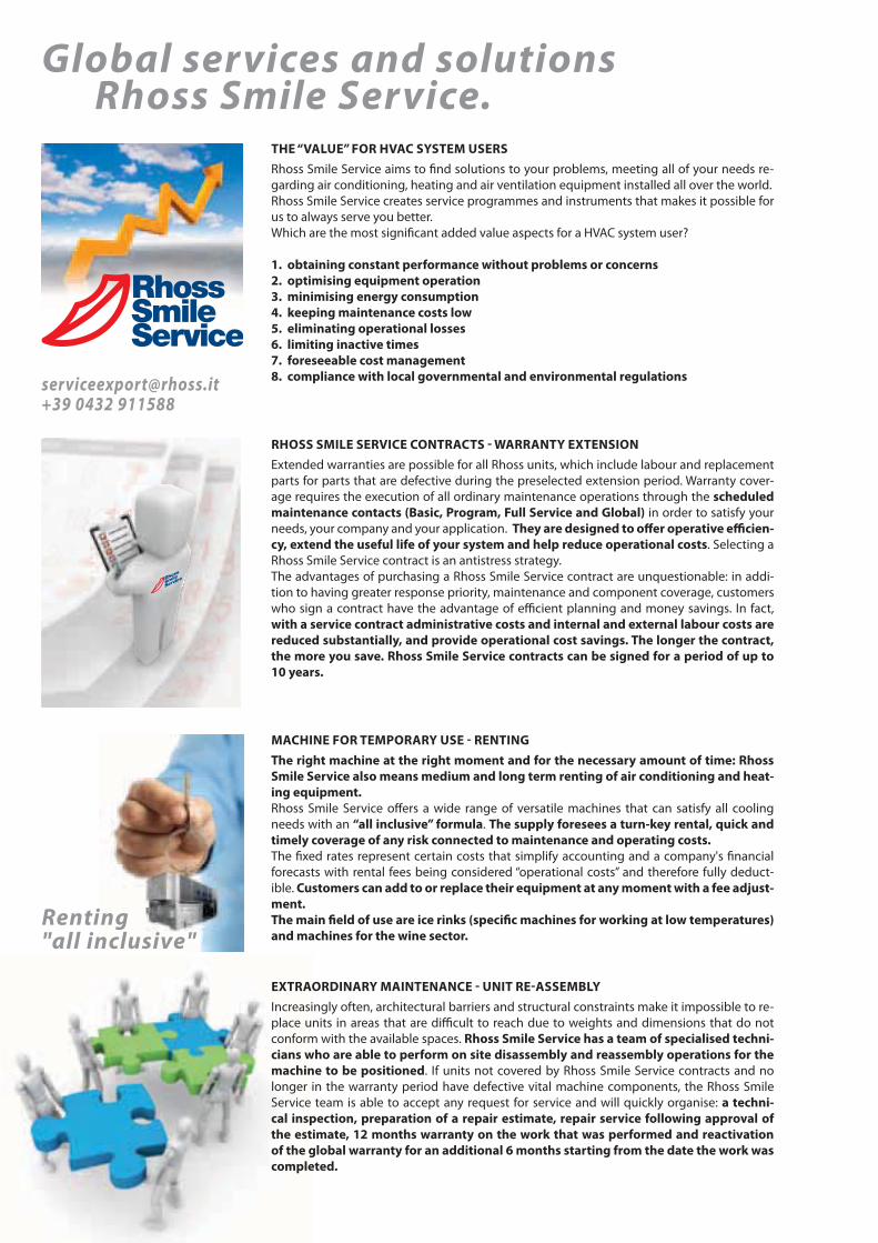
Global services and solutions Rhoss Smile Service.
THE “VALUE” FOR HVAC SYSTEM USERSRhoss Smile Service aims to fi nd solutions to your problems, meeting all of your needs re-garding air conditioning, heating and air ventilation equipment installed all over the world. Rhoss Smile Service creates service programmes and instruments that makes it possible for us to always serve you better. Which are the most signifi cant added value aspects for a HVAC system user?
1. obtaining constant performance without problems or concerns2. optimising equipment operation3. minimising energy consumption4. keeping maintenance costs low5. eliminating operational losses6. limiting inactive times7. foreseeable cost management8. compliance with local governmental and environmental regulations
RHOSS SMILE SERVICE CONTRACTS - WARRANTY EXTENSIONExtended warranties are possible for all Rhoss units, which include labour and replacement parts for parts that are defective during the preselected extension period. Warranty cover-age requires the execution of all ordinary maintenance operations through the scheduled maintenance contacts (Basic, Program, Full Service and Global) in order to satisfy your needs, your company and your application. They are designed to off er operative effi cien-cy, extend the useful life of your system and help reduce operational costs. Selecting a Rhoss Smile Service contract is an antistress strategy.The advantages of purchasing a Rhoss Smile Service contract are unquestionable: in addi-tion to having greater response priority, maintenance and component coverage, customers who sign a contract have the advantage of effi cient planning and money savings. In fact, with a service contract administrative costs and internal and external labour costs are reduced substantially, and provide operational cost savings. The longer the contract, the more you save. Rhoss Smile Service contracts can be signed for a period of up to 10 years.
MACHINE FOR TEMPORARY USE - RENTINGThe right machine at the right moment and for the necessary amount of time: Rhoss Smile Service also means medium and long term renting of air conditioning and heat-ing equipment. Rhoss Smile Service off ers a wide range of versatile machines that can satisfy all cooling needs with an “all inclusive” formula. The supply foresees a turn-key rental, quick and timely coverage of any risk connected to maintenance and operating costs. The fi xed rates represent certain costs that simplify accounting and a company's fi nancial forecasts with rental fees being considered “operational costs” and therefore fully deduct-ible. Customers can add to or replace their equipment at any moment with a fee adjust-ment.The main fi eld of use are ice rinks (specifi c machines for working at low temperatures) and machines for the wine sector.
EXTRAORDINARY MAINTENANCE - UNIT RE-ASSEMBLYIncreasingly often, architectural barriers and structural constraints make it impossible to re-place units in areas that are diffi cult to reach due to weights and dimensions that do not conform with the available spaces. Rhoss Smile Service has a team of specialised techni-cians who are able to perform on site disassembly and reassembly operations for the machine to be positioned. If units not covered by Rhoss Smile Service contracts and no longer in the warranty period have defective vital machine components, the Rhoss Smile Service team is able to accept any request for service and will quickly organise: a techni-cal inspection, preparation of a repair estimate, repair service following approval of the estimate, 12 months warranty on the work that was performed and reactivation of the global warranty for an additional 6 months starting from the date the work was completed.
Renting"all inclusive"
[email protected] +39 0432 911588

Web code: UTNR
Web code: UTNB
Web code: UTA1
Web code: UTNV
Web code: CTMO
Web code: CTCT-CTCR
Web code: DRP1-DRP2
14
ContentsAIR HANDLING
Recovery capacity: 5,4-18,6 kW
UTNRAir renewal terminal units with heat recoveryAir fl ow rate: 1.200-4.000 m/h
P. 16
Cooling capacity: 4,1-10,5 kW Heating capacity: 5,9-13,6 kW
UTNBDuctable terminal airhandling units in sectionsAir fl ow rate: 1.100-1.680 m⁄h
P. 18
Cooling: 7,2-108 kW Heating: 10,5-128,7 kW
UTNADuctable air handling terminal units in sectionsAir fl ow rate: 1.800-16.500 m/h
P. 20
Cooling: 14,5-98,2 kW Heating: 22,3-226,8 kW
UTNVVertical air conditioning, heating and ventilating terminal units.Air fl ow rate: 3.150-15.600 m/h
P. 22
Comfort range
MODULARAir handling unitsAir fl ow rate: 1.500-17.000 m/h
P. 24
Advance Range
CTA ADVAir handling unitsAir fl ow rate: 1.000-83.000 m/h
P. 34
Dry-Pool Range
DAESY-DRESY-DTESY-DEESYSwimming pool dehumidifi ersDehumidifi cation capacity: 8-140 l/h
P. 62

15
UT
NR
Fres
h ai
r ter
min
al u
nits
wit
h he
at re
cove
ry12
00-4
000
m³/h
UT
NB
Duct
able
term
inal
uni
ts11
00-1
680
m³/h
UT
NA
Duct
able
term
inal
uni
t18
00-1
6500
m³/h
UT
NV
Vert
ical
term
inal
uni
t31
50-1
5600
m³/h
MO
DU
LAR
Air h
andl
ing
unit
s 15
00-1
7000
m³/h
DR
Y-P
OO
LSw
imm
ing
pool
dehu
mid
ifi er
s
AD
V/R
Air h
andl
ing
unit
s 10
00-8
3000
m³/h

Web code: UTNR
16
Air renewal terminal units with heat recovery.
Construction features • Unit for environment air renewal with heat recovery: for horizontal
or vertical installation with dedicated accessory (KPAV).• Structure: load-bearing frame with extruded 30-mm aluminium
sections, glass-loaded nylon or painted aluminium nylon corners, and seals.
• Sandwich panels with a total thickness of 25 mm, in double galvanised sheet steel, hot-injected polyurethane insulation, density 45 kg/m.
• Module with recovery unit: aluminium air-air type package recovery unit with rough surface plates, housed in a built-in condensation collection tray in galvanised steel.
• Filters: folded, thickness 48 mm (thickness 98 mm on UTNR 032 and 041), as standard on external air, with effi ciency rating of G3, extractable from below.
• Fan module: double inlet centrifugal electric fans directly connected at 3 speeds with protection rating IP44 (IP 20 on UTNR 041).
ACCESSORY MODULES• MBF - External module with additional water 4-row coil, complete
with condensation drain pan for heating and/or cooling (for horizontal installations only).
• KPAV - Plenum with side openings for vertical unit installation, designed to house the fi lter accessory and dampers.
ACCESSORIES SUPPLIED LOOSE• Two-range additional water heating coils, with left-hand
connections.• Electric heater in carbon steel with galvanised steel fi ns (available
in versions with single-phase and three-phase power supply).• Air outlet synthetic fi lters.• Air outlet metal fi lters.• Galvanised steel damper on external air inlet and/or outlet.
STANDARD CONTROLSFor wall installation
Panel with speed and summer/winter switch. Panel with room thermostat, summer/winter switch, speed switch, ON/OFF valve signal and electric heater.
Key: Supplied loose
UTNR 012÷041Recovery capacity: 5,4-18,6 kW
• Horizontal or vertical installation
• Coil module for summer or winter integration
• Accessories for simple installation
Additional module with cold/hot coil (MBF)
UTNR
UTNRUTNR
Plenum for vertical installation (KPAV)

17
UT
NR
Fres
h ai
r ter
min
al u
nits
wit
h he
at re
cove
ry12
00-4
000
m³/h
UT
NB
Duct
able
term
inal
uni
ts11
00-1
680
m³/h
UT
NA
Duct
able
term
inal
uni
t18
00-1
6500
m³/h
UT
NV
Vert
ical
term
inal
uni
t31
50-1
5600
m³/h
MO
DU
LAR
Air h
andl
ing
unit
s 15
00-1
7000
m³/h
DR
Y-P
OO
LSw
imm
ing
pool
dehu
mid
ifi er
s
AD
V/R
Air h
andl
ing
unit
s 10
00-8
3000
m³/h
In the following conditions: Expelled air: 20°C D.B. - 50% R.H.; Renewal air –5°C D.B., 80% R.H. Maximum speed.
Water 70°C with Δt 10°C. Maximum speed. Unit without accessories, with standard fi lter. At 3 m from air outlet, with free nozzle and directionality factor of 2. Unit with standard fi lter and external MBF module. Water 7/12°C. Maximum speed. Water 45/40°C. Maximum speed.
UTNR MODEL
Recovery efficiency %
Recovery capacity kW
Heating capacity of additional coil kW
Air flow rate/ MAX m/h / Pa
Static supply pressure. MED m/h / Pa
Speed MIN m/h / Pa
Sound pressure level MAX dB(A)
supply. Speed MED dB(A)
MIN dB(A)
Air flow rate/ MAX m/h / Pa
Static return pressure MED m/h / Pa
Speed MIN m/h / Pa
Sound pressure level MAX dB(A)
return. Speed MED dB(A)
MIN dB(A)
Air flow rate/Static press. introduced. MBF add. module MAX speed m³/h - Pa
Total cooling capacity additional module MBF MAX speed kW
Heating capacity additional module MBF MAX speed kW
Maximum absorbed supply/return power W
Mains supply V-ph-Hz
DIMENSIONS AND WEIGHTS
L/H/P - Width/Height/DepthUTNR mm
L΄/H΄/P΄ - Width/Height/Depth MBF mm
L˝/H˝/P˝ - Width/Height/Depth KPAV mm
WeightUTNR (with water coil) kg
Weight MBF kg
Weight KPAV kg
012 017 023 032 041
50 52 52 50 50
5,44 8,02 10,89 14,51 18,59
10,30 15,68 21,08 28,78 37,59
1.200 / 100 1.700 / 120 2.300 / 150 3.200 / 120 4.100 / 160
1.050 / 100 1.450 / 120 1.850 / 150 2.600 / 120 3.400 / 160
925 / 100 1.150 / 120 1.550 / 150 2.100 / 120 2.600 / 160
57 56 58 60 60
54 53 56 58 58
52 52 53 52 55
1.200 / 100 1.550 / 120 2.300 / 150 2.880 / 120 4.000 / 160
1.050 / 100 1.300 / 120 1.650 / 150 2.430 / 120 2.850 / 160
925 / 100 1.150 / 120 1.020 / 150 2.020 / 120 1.850 / 160
53 55 58 62 58
52 54 54 59 55
49 50 49 54 50
1.000 / 56 1.500 / 88 2.100 / 93 2.800 / 73 3.950 / 81
7,00 11,84 16,02 21,06 28,62
9,41 14,02 19,1 24,32 34,1
415/315 545/480 590/655 810/895 1.245/1.245
230-1-50 230-1-50 230-1-50 230-1-50 230-1-50
012 017 023 032 041
1.000/440/1.260 1.140/520/1.380 1.200/520/1.500 1.260/600/1.700 1.480/620/1.760
650/440/670 750/520/670 750/520/670 850/600/670 950/620/670
1.000/440/440 1.140/520/520 1.200/520/520 1.260/600/600 1.480/620/620
90 90 90 150 230
37 45 45 54 60
20 24 28 30 35
EXTE
RNA
L
INTE
RNA
L
HORIZONTAL installation with MBF module
EXTE
RNA
L
INTE
RNA
L
VERTICAL installationHORIZONTAL installation
INTERNAL
EXTERNAL
Plenum for vertical installation
(KPAV)

Web code: UTB1Web code accessories: UTB2
18
UTNB: air return with multi-channel inlet and outlet panelling.
Ductable terminal air handling units in sections
Construction features • Air handling unit: in modules for installation in false ceiling, with
ducting or panelling (29 cm in height).• Heat exchanger: with fi nned coil with right-hand connections
reversible to left.• Fan: centrifugal 3-speed (IP44).• Structure: load-bearing in galvanized sheet metal complete
with thermo-acoustic insulation, renewable fi lter, connection for attachment to inlet duct and condensation drain pan with natural drainage.
Accessories supplied loose• Additional water heating coil.• inlet/outlet plenum (KPAM).• Electric coil module of 1.5-3-4.5 kW (KBAE).• Plenum with steam humidifi er (KUMI).• Outlet nozzles module (KBOM).• Inlet panelling.• Solid panelling.• Outlet panelling.
STANDARD CONTROLSFor wall installation
Panel with speed and summer/winter switch. Panel with room thermostat, summer/winter switch, speed switch, ON/OFF valve signal.
Humidistat panel. Electronic panel with automatic summer/winter changeover for 2-pipe-systems.
Electronic panel with automatic summer/winter changeover and automatic speed regulation for 2-pipe-systems with electric heater or 4-pipe-systems.
Interface card for controlling up to 4 fan coil units.
CONTROLS Remote control receiver. Electronic control panel for wall mounting. Wall-mounted electronic panel
For installation on machine. Master/slave electronic card. Temperature probe for hot row. Module for management of ON/OFF valves and electric heater. Serial interfaces for connection to BMS (proprietary protocol, Modbus RTU).
Serial converters (RS485/RS232, RS485/USB) in the case of centralised unit management.
Serial interface (CAN-bus - Controller Area Network) for the iDRHOSS system.
Key: Supplied loose
UTNB 011÷017Cooling capacity: 4,1÷10,5 kW - Heating capacity: 5,9÷13,6 kW
Recessed control panel•
Remove control with wall-mounted receiver
•Wall-mounted control panel
RECEIVER

19
UT
NR
Fres
h ai
r ter
min
al u
nits
wit
h he
at re
cove
ry12
00-4
000
m³/h
UT
NB
Duct
able
term
inal
uni
ts11
00-1
680
m³/h
UT
NA
Duct
able
term
inal
uni
t18
00-1
6500
m³/h
UT
NV
Vert
ical
term
inal
uni
t31
50-1
5600
m³/h
MO
DU
LAR
Air h
andl
ing
unit
s 15
00-1
7000
m³/h
DR
Y-P
OO
LSw
imm
ing
pool
dehu
mid
ifi er
s
AD
V/R
Air h
andl
ing
unit
s 10
00-8
3000
m³/h
KPAMInlet/outlet plenum
UTNBBase unit
KBAEElectric coil module
KUMIPlenum with humidifier
KBOMNozzles modulefor inlet
In the following conditions: Air: 27°C D.B.; 19°C W.B. - Water: 7/12°C. Maximum speed, with open outlet. Air: 20°C - Water: 50°C, fl ow rate as in cooling.
Maximum speed, with open outlet. Air: 20°C - Water: 70/60°C. At 3 m from the point of air outlet, with open outlet.
UTNB MODEL
Total cooling capacity kW
Heating capacity kW
Heating capacity of additional coil kW
Air flow speed MAX m/h
MED m/h
MIN m/h
Sound pressure speed MAX dB(A)
MED dB(A)
MIN dB(A)
Maximum absorbed power W
Mains supply V-ph-Hz
DIMENSIONS AND WEIGHTS
W - Width mm
H - Height mm
KPAM - Depth mm
UTNB - Depth mm
KBAE - Depth mm
KUMI - Depth mm
KBOM - Depth mm
Weight UTNB kg
011 2R 011 4R 011 6R 014 2R 014 4R 014 6R 017 2R 017 4R 017 6R
4,11 6,76 7,78 4,82 8,23 9,64 5,14 8,92 10,52
5,92 8,75 9,58 7,17 11,02 12,27 7,76 12,12 13,59
10,02 10,02 10,02 12,37 12,37 12,37 13,49 13,49 13,49
1.100 1.100 1.100 1.480 1.480 1.480 1.680 1.680 1.680
990 990 990 1.260 1.260 1.260 1.440 1.440 1.440
850 850 850 1.100 1.100 1.100 1.200 1.200 1.200
41 41 41 47 47 47 50 50 50
40 40 40 44 44 44 46 46 46
38 38 38 41 41 41 41 41 41
165 165 165 205 205 205 245 245 245
230-1-50 230-1-50 230-1-50 230-1-50 230-1-50 230-1-50 230-1-50 230-1-50 230-1-50
011 2R 011 4R 011 6R 014 2R 014 4R 014 6R 017 2R 017 4R 017 6R
990 990 990 990 990 990 990 990 990
290 290 290 290 290 290 290 290 290
290 290 290 290 290 290 290 290 290
738 738 738 738 738 738 738 738 738
130 130 130 130 130 130 130 130 130
290 290 290 290 290 290 290 290 290
100 100 100 100 100 100 100 100 100
38 42 46 38 42 46 40 44 48
(*) Unit dimensions in combination with KPAM plenum.

Web code: UTA1Web code accessories: UTA2
20
MUVPlenum with humidifier
PMAPlenumfor inlet/outlet
BACoil module
SVFan module
KPBCPanel with circular nozzles
KPBMPanel with outlet nozzle
KB2RCoiladditional heating
SILPlenumwith silencer
PRVSteam producer
PMAInlet/Outlet plenum
KSERDamper
Complete composition
Ductable terminal air handling units in sections
Construction features • Air handling unit: in sections for horizontal installation either with
or without ducting.• Structure: in galvanized steel sheet metal, with fully removable
pre-painted sheet metal panelling, complete with self-extinguishing thermo-acoustic insulation.
• Module BA 2R, BA 4R, BA 6R: complete with pleated fi lter in 2 sections with degree of effi ciency G3, can be slid out in all directions; heat exchanger with fi nned coil, with 2 or 4 or 6 rows with reversible right-hand connections; condensation drain pan with natural drainage.
• Fan module SV: complete with centrifugal fan with double inlet with motor (IP55) directly coupled, 3-speed for models 015÷038; 2-speed for model 051; with 4-pole single speed motor (4/6 or 4/8 poles on request) coupled by means of trapezoidal belt and variable pulley for models 078-150.
• Electrical board: standard for models 051÷150; accessory for models 015÷038.
Accessory modules• Inlet/outlet plenum with pre-cut side outlets (PMA).• Plenum with absorbent cartridge silencer to be placed for inlet or
outlet (SIL).• Plenum with steam humidifi er and external electric generator
(MUV - PRV).
ACCESSORIES SUPPLIED LOOSE• Additional water heating coil to be inserted in module BA.• Supplementary electric heater from 1.5 kW to 36 kW, to be
inserted in module BA.• Droplet eliminator for models 078÷150, to be inserted in module
BA.• Combined fresh air damper (max 25%) and re-circulation, to be
attached to the PMA inlet plenum.• Solid pre-cut panel for connection to duct, to be attached to the
PMA inlet plenum.• Panel with rectangular outlet nozzle with double row of adjustable
fi ns, to be attached to PMA outlet plenum.• Panel with circular nozzles, to be attached to PMA inlet/outlet
plenum (only for models 015÷051).• Manual control for KSER damper.• Electrical panel in waterproof box (IP55 for UTNA 015÷038).
STANDARD CONTROLSFor wall installation
Panel with speed and summer/winter switch. Panel with room thermostat, summer/winter switch, speed switch, ON/OFF valve signal.
Humidistat panel. Electronic panel with automatic summer/winter changeover for 2-pipe-systems.
Electronic panel with automatic summer/winter changeover and automatic speed regulation for 2-pipe-systems with electric heater or 4-pipe-systems.
CONTROLS Remote control receiver. Electronic control panel for wall mounting. Wall-mounted electronic panel
For installation on machine. Master/slave electronic card. Temperature probe for hot row. Module for management of ON/OFF valves and electric heater. Serial interfaces for connection to BMS (proprietary protocol, Modbus RTU).
Serial converters (RS485/RS232, RS485/USB) in the case of centralised unit management.
Serial interface (CAN-bus - Controller Area Network) for the iDRHOSS system.
Key: Factory fi tted Supplied loose
UTNA 015÷150Cooling capacity: 7,2÷108 kW - Heating capacity: 10,5÷128,7 kW

21
UT
NR
Fres
h ai
r ter
min
al u
nits
wit
h he
at re
cove
ry12
00-4
000
m³/h
UT
NB
Duct
able
term
inal
uni
ts11
00-1
680
m³/h
UT
NA
Duct
able
term
inal
uni
t18
00-1
6500
m³/h
UT
NV
Vert
ical
term
inal
uni
t31
50-1
5600
m³/h
MO
DU
LAR
Air h
andl
ing
unit
s 15
00-1
7000
m³/h
DR
Y-P
OO
LSw
imm
ing
pool
dehu
mid
ifi er
s
AD
V/R
Air h
andl
ing
unit
s 10
00-8
3000
m³/h
BACoil module
SVFan module
In the following conditions: Air: 27°C D.B.; 19°C W.B. - Water: 7/12°C. Maximum speed. Air: 20°C - Water: 50°C, fl ow rate as in cooling.
Maximum speed. Air: 20°C - Water: 70/60°C. 4-row coil (BA 4R) and fi lter G3. At 3 m from the point of air outlet, with open outlet. Empty weight BA 6R.
(*) Belt transmission with variable ratio.
UTNA MODEL
Heating. capacity of . additional coil BA 2R/KB2R kW
Cooling capacity BA-4R kW
Heating capacity BA 4R kW
Cooling capacity BA 6R kW
Heating capacity BA 6R kW
Electric heater power 230V-1ph-50Hz kW
electric 400V-3ph-50Hz kW
Air flow speed MAX m/h
MED m/h
MIN m/h
Static pressure speed MAX Pa
Sound pressure speed MAX dB(A)
MED dB(A)
MIN dB(A)
Absorbed power W
Mains supply V-ph-Hz
DIMENSIONS AND WEIGHTS
W - Width mm
H - Height mm
PMA - Depth mm
BA - Depth mm
SV - Depth mm
SIL-MUV - Depth mm
Weight UTNA kg
015 020 029 038 051 078 107 130 150
11,3 14,2 20,7 25,8 35,2 57,5 82,6 92,7 106,0
7,2 8,8 13,9 17,3 21,4 41,8 60,6 67,8 77,1
10,5 13,4 19,3 24,6 32,4 54,4 77,9 88,9 101,6
9,9 12,5 17,9 22,4 30,9 55,6 82,7 94,4 108,0
13,3 17,7 24,0 30,6 42,5 67,3 96,7 112,3 128,7
1,5-3-4,5 3-4,5-6 4,5-6-9 6-9-12 – – – – –
1,5-3-4,5 3-4,5-6 4,5-6-9 6-9-12 9-12-18 12-18-24 18-24-36 18-24-36 24-36
1.800 2.640 3.220 4.260 6.120 8.580 (*) 11.770 (*) 14.300 (*) 16.500 (*)
1.370 2.240 2.400 3.500 – – – – –
1.060 1.480 1.560 2.850 4.390 – – – –
90 90 90 90 130 170 160 145 140
50,9 55,6 54,9 59,8 61,5 59,7 61,7 65,4 61,9
44,3 50,2 48,3 55,7 – – – – –
37,1 42,1 38,7 51,4 54,4 – – – –
370 700 700 1.250 1.850 1.500 1.500 2.200 3.000
230-1-50 230-1-50 230-1-50 230-1-50 400-3-50 400-3-50 400-3-50 400-3-50 400-3-50
015 020 029 038 051 078 107 130 150
928 928 1.228 1.228 1.328 1.658 2.058 2.058 2.058
398 398 463 518 568 768 918 918 1.018
370 370 435 490 540 740 890 890 990
645 645 645 645 645 910 910 910 910
370 370 435 490 490 1.040 1.040 1.040 1.040
960 960 960 960 960 1.040 1.040 1.040 1.040
51 51 68 71 79 140 200 200 220
Base composition
RECEIVER

Web code: UTNV
22 UTNV 030÷150Cooling capacity: 14,5÷98,2 kW - Heating capacity: 22,3÷226,8 kW
Front filter extraction and inlet grille.
• Vertical installation
Air conditioning, heating and ventilating terminal units.
Construction features• Air conditioning, heating and ventilating unit: for vertical
installation with or without ducting.• Structure: packaged composed of treatment section and fan
assembly with load-bearing frame in double-chamber extruded aluminium profi les with concealed screws, corner joints in black nylon, glass reinforced.
• Removable panelling in double sheet metal, in galvanized steel on the inside and pre-painted with protection fi lm on the outside, with expanded polyurethane inserted (density 45 kg/m3) and total thickness of 25 mm.
• Base with extruded aluminium profi les.• Handling section composed of: pleated renewable multi-section
fi lters with degree of effi ciency G3, can be extracted from front (or from side with KEF accessory), heat exchanger with fi nned coil with 2-4-6 rows with connections on the right or left and galvanized steel condensation drain pan with natural drainage. On request the water connections can be located on the right or left side of the unit.
• Electric fan assembly: with upper or front outlet composed of double inlet centrifugal fans with forward rotors with anti-vibration joint on pressing mouth, tri-phase motor (IP55), variable pulley and trapezoidal belt drive (up to model 080), anti-vibration rubber mountings.
Versions• M - Single-phase motor for models 030-050 with adjustable pulley.• T6 - Tri-phase 4/6-pole motor with adjustable pulley.• T8 - Tri-phase 4/8-pole motor with adjustable pulley.• E - Treatment section with side opening for fresh air inlet.• B2R - Additional coil with 2 rows for 4-pipe systems for UTNV 4R
and UTNV 6R.• B2P - Additional coil with 2 post-heating rows for UTNV 4R and
UTNV 6R.• EFL - Side extraction of fi lters on opposite side from water
connections.
Accessory modules• Outlet plenum, with aluminium nozzles with double row of
adjustable fi ns.• Outlet plenum, with galvanized steel nozzles with double row of
fi ns.
ACCESSORIES SUPPLIED LOOSE• Inlet grille in galvanized steel.• Inlet grille in aluminium.• Side extraction of fi lters on opposite side from water connections.• Panel with room thermostat, summer/winter switch, speed switch
ON/OFF valve signal.
Side filter extraction on request.
UTNV with outlet plenum.

H
LP
23
UT
NR
Fres
h ai
r ter
min
al u
nits
wit
h he
at re
cove
ry12
00-4
000
m³/h
UT
NB
Duct
able
term
inal
uni
ts11
00-1
680
m³/h
UT
NA
Duct
able
term
inal
uni
t18
00-1
6500
m³/h
UT
NV
Vert
ical
term
inal
uni
t31
50-1
5600
m³/h
MO
DU
LAR
Air h
andl
ing
unit
s 15
00-1
7000
m³/h
DR
Y-P
OO
LSw
imm
ing
pool
dehu
mid
ifi er
s
AD
V/R
Air h
andl
ing
unit
s 10
00-8
3000
m³/h
030 050 080 100 125 150
22,3 40,5 61,3 77,5 95,1 114,9
14,5 27,6 40,5 52,6 63,6 77,6
37,6 68,3 101,6 130,1 159,2 190,8
19,2 33,9 51,8 65,5 81,4 98,2
44,9 80,6 122,1 153,8 189,2 226,8
22,3 40,5 61,3 77,5 95,1 114,9
3.150 5.600 8.500 10.600 13.100 15.600
170 170 170 173 170 172
60,0 62,9 62,7 69,2 66,0 64,6
0,75 1,50 2,20 3,00 4,00 4,00
230-1-50 230-1-50 230-1-50 400-3-50 400-3-50 400-3-50
400-3-50 400-3-50 400-3-50
030 050 080 100 125 150
1.000 1.200 1.500 1.750 2.050 2.400
1.600 1.800 2.000 2.000 2.000 2.000
1.800 2.000 2.200 2.200 2.200 2.200
680 760 840 840 840 840
165 270 360 465 520 570
UTNV MODEL
Nominal heating capacity UTNV 2R kW
Nominal cooling capacity UTNV 4R kW
Nominal heating capacity UTNV 4R kW
Nominal cooling capacity UTNV 6R kW
Nominal heating capacity UTNV 6R kW
Nominal. heating capacity of additional coil B2R-B2P kW
Air flow max. m/h
Available head pressure max. UTNV 4R Pa
Sound pressure level max. dB(A)
/ Absorbed power kW
Main supply V-ph-Hz
DIMENSIONS AND WEIGHTS
W - Width mm
H - Height UTNV 2R/4R/6R/4R+2R/2R+4R mm
H - Height 6R+2R mm
D - Depth mm
Weight kg
In the following conditions: Air: 27°C D.B.; 19°C W.B. - Water: 7/12°C. Maximum speed. Air: 20°C - Water: 70/60°C. Maximum speed. At 3 m from the point of air outlet.
GREENLINE
Web code: CTMO
24
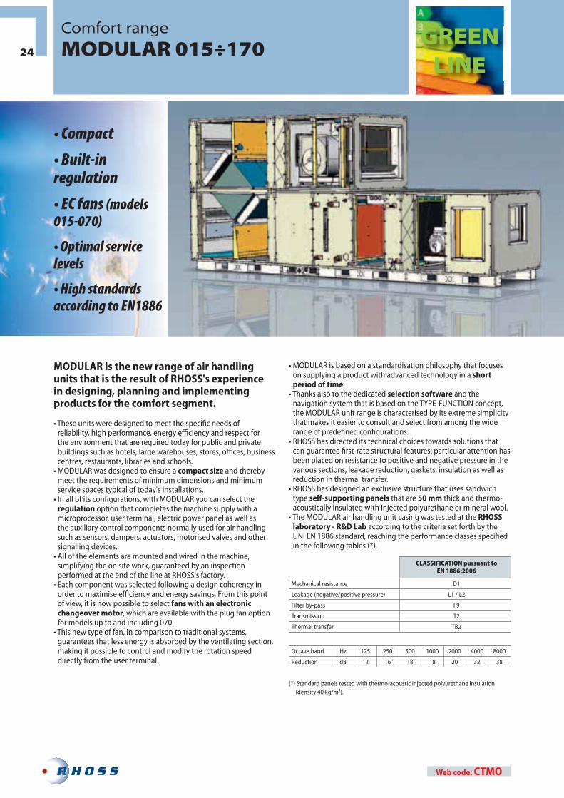
Comfort rangeMODULAR 015÷170
CLASSIFICATION pursuant toEN 1886:2006
Mechanical resistance D1
Leakage (negative/positive pressure) L1 / L2
Filter by-pass F9
Transmission T2
Thermal transfer TB2
Octave band Hz 125 250 500 1000 2000 4000 8000
Reduction dB 12 16 18 18 20 32 38
(*) Standard panels tested with thermo-acoustic injected polyurethane insulation (density 40 kg/m³).
MODULAR is the new range of air handling units that is the result of RHOSS's experience in designing, planning and implementing products for the comfort segment.
• These units were designed to meet the specifi c needs of reliability, high performance, energy effi ciency and respect for the environment that are required today for public and private buildings such as hotels, large warehouses, stores, offi ces, business centres, restaurants, libraries and schools.
• MODULAR was designed to ensure a compact size and thereby meet the requirements of minimum dimensions and minimum service spaces typical of today's installations.
• In all of its confi gurations, with MODULAR you can select the regulation option that completes the machine supply with a microprocessor, user terminal, electric power panel as well as the auxiliary control components normally used for air handling such as sensors, dampers, actuators, motorised valves and other signalling devices.
• All of the elements are mounted and wired in the machine, simplifying the on site work, guaranteed by an inspection performed at the end of the line at RHOSS's factory.
• Each component was selected following a design coherency in order to maximise effi ciency and energy savings. From this point of view, it is now possible to select fans with an electronic changeover motor, which are available with the plug fan option for models up to and including 070.
• This new type of fan, in comparison to traditional systems, guarantees that less energy is absorbed by the ventilating section, making it possible to control and modify the rotation speed directly from the user terminal.
• MODULAR is based on a standardisation philosophy that focuses on supplying a product with advanced technology in a short period of time.
• Thanks also to the dedicated selection software and the navigation system that is based on the TYPE-FUNCTION concept, the MODULAR unit range is characterised by its extreme simplicity that makes it easier to consult and select from among the wide range of predefi ned confi gurations.
• RHOSS has directed its technical choices towards solutions that can guarantee fi rst-rate structural features: particular attention has been placed on resistance to positive and negative pressure in the various sections, leakage reduction, gaskets, insulation as well as reduction in thermal transfer.
• RHOSS has designed an exclusive structure that uses sandwich type self-supporting panels that are 50 mm thick and thermo-acoustically insulated with injected polyurethane or mineral wool.
• The MODULAR air handling unit casing was tested at the RHOSS laboratory - R&D Lab according to the criteria set forth by the UNI EN 1886 standard, reaching the performance classes specifi ed in the following tables (*).
• Compact
• Built-in regulation
• EC fans (models 015-070)
• Optimal service levels
• High standards according to EN1886

0
1500
3000
4500
6000
7500
9000
10500
12000
13500
15000
16500
18000
19500
21000
22500
24000
015
020
026
035
050
070
092
115
140
170
770
770
950
950
950
1.165
1.365
1.500
1.500
1.500
730
730
860
930
1.235
1.345
1.345
1.550
1.645
1.960
H
B
25
UT
NR
Fres
h ai
r ter
min
al u
nits
wit
h he
at re
cove
ry12
00-4
000
m³/h
UT
NB
Duct
able
term
inal
uni
ts11
00-1
680
m³/h
UT
NA
Duct
able
term
inal
uni
t18
00-1
6500
m³/h
UT
NV
Vert
ical
term
inal
uni
t31
50-1
5600
m³/h
MO
DU
LAR
Air h
andl
ing
unit
s 15
00-1
7000
m³/h
DR
Y-P
OO
LSw
imm
ing
pool
dehu
mid
ifi er
s
AD
V/R
Air h
andl
ing
unit
s 10
00-8
3000
m³/h
• The range includes 10 models that cover an air fl ow rate range between 1.500 and 17.000 m³/h with a frontal coil crossing speed of 2,5 m/s.
• Within the fl ow rate range covered by each model, the colours help with the selection of the size based on the desired handling performance:
- maximum coil crossing speed of 3,0 m/s for units with a cold coil and/or humidifi er;
- maximum coil crossing speed of 3,5 m/s for units with heating only.
2,0 m/s 3,0 m/s
3,5 m/s
2,0 m/s 3,0 m/s
3,5 m/s
Air fl ow rate (m³/h)
B H Model

26
STRUCTUREAn exclusive self-supporting panel system that guarantees a high degree of rigidity, lack of thermal transfer and perfect quadrature.The inner surface does not have any discontinuities to minimise the collection of dust and to make cleaning and maintenance operations easier.
PANELSDual walls, 50 mm thick with expanded polyurethane insulation with a density of 40 kg/m³ or mineral wool insulation with a density of 90 kg/m³. Galvanized steel and RAL9002 prepainted galvanized steel are available, respectively, for the internal and external sides. Nylon handles are provided for sections that are inspected frequently.
INNER STRUCTUREThe fi lter holder frames, coil holding frames, plugging and the entire remaining internal structure are made out galvanised sheet steel.
JOINTSAn original quick coupling system that makes quick on site assembly possible for units supplied in multiple sections
ROOFIn prepainted galvanized steel .The roof sticks out all around the unit. It is foreseen for outdoor installation AHUs in order to avoid water stagnation and allow a perfect water tightness even in correspondence of the sections junctions.
BASEMade of two press formed galvanised sheet metal longitudinal members, it guarantees minimum defl ection and perfect stability for the entire structure. In the case of a supply with multiple sections, each has its own base.
DAMPERSThe structures always contain dampers with opposing aluminium fi ns with a wing profi le and a longitudinal plastic gasket. Prepared for the installation of a servo control.
FILTERSFor primary fi ltration, the standard confi guration always includes a class G4 pleated synthetic cell fi lter.For more effi cient fi ltration, an additional rigid bag fi lter in classes F5, F7 or F9 can be selected..
HEAT RECOVERYA unit with crossed-fl ow plates with lateral by-pass for free-cooling and recirculation damper, complete with a class G4 pleated synthetic cell fi lter and galvanised steel condensation collection tray.
COILSUsing water or glycol water, packaged with copper pipes and aluminium fi ns. Copper manifolds with brass or stainless steel terminals. In the case of a cold battery and without a humidifi cation section, there is always a polypropylene droplet eliminator.
Comfort rangeMODULAR 015÷170Main Features

27
UT
NR
Fres
h ai
r ter
min
al u
nits
wit
h he
at re
cove
ry12
00-4
000
m³/h
UT
NB
Duct
able
term
inal
uni
ts11
00-1
680
m³/h
UT
NA
Duct
able
term
inal
uni
t18
00-1
6500
m³/h
UT
NV
Vert
ical
term
inal
uni
t31
50-1
5600
m³/h
MO
DU
LAR
Air h
andl
ing
unit
s 15
00-1
7000
m³/h
DR
Y-P
OO
LSw
imm
ing
pool
dehu
mid
ifi er
s
AD
V/R
Air h
andl
ing
unit
s 10
00-8
3000
m³/h
FAN SECTIONSafety switch installed at factory on the access panel.
standard confi guration comprehends dual intake fans coupled to electric motors with a belt and pulley transmission.
Free impeller PLUG-FUN are also available on all models
Starting from model 015 up to including model 070, the option PLUG FAN is always equipped with electronic brushless motor.
HUMIDIFICATIONAdiabatic version with evaporating bloch with open water circuit or isothermal version with autonomous steam producer. The humidifi cation section always has a polypropylene droplet eliminator.
CONDENSATION DRAIN PANIn galvanised steel and sloped for perfect drainage to the drain.
ELECTRIC COILMulti-stage with armoured heaters and spiral fi n.
ACCESSORIES SUPPLIED LOOSE
SILENCER Made of modular rectangular sections cartridges in sound-absorbing material made of fi brous textile nature.
ANTIVIBRATION JOINTS For connecting ducts to the machine.
INVERTER Complete with an inlet fi lter and programming keyboard, they are supplied loose and are mounted and wired by the customer. All motors in the MODULAR range can be controlled by the inverter.

28
Comfort rangeMODULAR 015÷170Regulation option
AIR TEMPERATURE AND HUMIDITY PROBESUsed to acquire the air temperature and humidity measurements, their number and type change depending on the machine confi guration:• outdoor air temperature probe;• outdoor air humidity probe;• recovery air temperature probe;• recovery air humidity probe;• supply limit temperature probe;• ambient temperature probe;• ambient humidity probe.
DAMPER ACTUATORSAlready assembled and wired, these are the components that actuate the air passage dampers. Based on the machine confi guration, they can have an on-off or modulating control, with or without a spring return.
FILTER DIFFERENTIAL PRESSURE SWITCH This provides an alarm signal for a dirty fi lter that reaches the set pressure value limit. Assembled inside the unit in correspondence of the fi ltering section.
WATER COILS They feature the entire hydraulic assembly, including a three-way stopper housing valve, modulating servo control and balancing valves on the by-pass.
ANTIFREEZE THERMOSTATAssembled behind the hot coil, it protects the heat exchangers from the risk of freezing if temperatures go down below a preset threshold value, causing the fan to stop, the external air damper to close and the hot coil to be activated to restore normal operation.
TECHNICAL SPACE (for external installation)Included at the side near the regulation components.Made with pre-painted galvanized steel.
FAN DIFFERENTIAL PRESSURE SWITCHThis provides an alarm signal if there is no air fl ow, caused by a ventilating section fault. Assembled inside the unit in correspondence of the ventilating section.
MICROSWITCHEach ventilating section has a wired, non-excludable safety microswitch
HUMIDIFICATION MANAGEMENTThis is performed by the unit's regulation system, both in the case of adiabatic packaged evaporating type humidifi cation (on-off control) as well as isothermal humidifi cation with an autonomous steam producer (modulating control).

29
UT
NR
Fres
h ai
r ter
min
al u
nits
wit
h he
at re
cove
ry12
00-4
000
m³/h
UT
NB
Duct
able
term
inal
uni
ts11
00-1
680
m³/h
UT
NA
Duct
able
term
inal
uni
t18
00-1
6500
m³/h
UT
NV
Vert
ical
term
inal
uni
t31
50-1
5600
m³/h
MO
DU
LAR
Air h
andl
ing
unit
s 15
00-1
7000
m³/h
DR
Y-P
OO
LSw
imm
ing
pool
dehu
mid
ifi er
s
AD
V/R
Air h
andl
ing
unit
s 10
00-8
3000
m³/h
FREE-COOLING MANAGEMENTThis is performed by the unit's regulation system and is based on an enthalpic comparison between the internal environment and the external environment. Damper management possible either via a potentiometer or an air quality probe.
PLUG FAN MANAGEMENTIncluded with the regulation option, the control logic for the PLUG FAN can be managed throgh: • display;• potentiometer;• air quality probe;• at constant pressure.
SUPERVISIONThe MODULAR range can interact with BMS systems, exchanging data across the most common communication protocols such as MODBUS and LON.
FACTORY FITTED ACCESSORIES
• MODBUS RTU serial interface.
• LON serial interface.
SUPPLIED LOOSE ACCESSORIES
• Remote control panel.
• Ambient panel.
• Potentiometer for damper or inverter management.
• Air quality probe for damper or inverter management.
POWER AND REGULATION ELECTRICAL BOXAssembled on board the machine in correspondence of the supply fan section, it includes a programmed microprocessor regulator, expansion cards, transformers, drivers, safety device lamps and main disconnecting switch. Electrical power supply 400V/3+N/50Hz.Auxiliary power supply 24V.
MICROPROCESSORBased on a specifi c software that compares the set values with the thermohygrometric conditions measured by the sensors, it guarantees optimal control of all the unit's safety mechanisms and operating parameters. Thanks to the expansion cards, it is possible to manage all of the confi gurations and treatments possible for the MODULAR air handling unit.
USER TERMINALWith an LCD display and keyboard, it has a control-management menu and the messaging system necessary for unit assembly and maintenance.

30
Comfort rangeMODULAR 015÷170Selection: TYPE and FUNCTION
The ease in selecting a MODULAR range unit is based on the concept of TYPE and FUNCTION.The TYPE of unit solution is a major plant engineering requirement and it is related to a predefi ned number of FUNCTIONS.
TYPE EEXTRACTOR
Simple autonomous extractor or an extractor combined with a handling unit that works with primary air or 100% external air.
TYPE R100% RECIRCULATION
For 100% recirculation systems that do not require a combined extraction system.
TYPE F100% EXTERNAL AIR
For primary air or 100% external air systems.Possible combination with Rhoss (TYPE E) extractors or extractors not supplied by Rhoss.
TYPE MMIXING BOX
This makes it possible to manage the mixture of external and recirculation air.
TYPE VVERTICAL RECIRCULATION/EXPULSION BOX
This permits the expulsion of the extracted air and the mixing of external air with recirculation air.
TYPE HHORIZONTAL RECIRCULATION/EXPULSION BOX
This permits the expulsion of the extracted air and the mixing of external air with recirculation air. The horizontal implementation is recommended in areas with reduced height.
TYPE XVERTICAL CROSSED FLOWHEAT RECOVERY
This is necessary in the case of not only a request for handling but also for an energy recovery system in order to reduce consumption for air conditioning. The vertical implementation is recommended in areas with reduced surface space.
TYPE WHORIZONTAL CROSSED-FLOW HEAT RECOVERY
This is necessary in the case of not only a request for handling but also for an energy recovery system in order to reduce consumption for air conditioning.
FUNCTION
FUNCTION
FUNCTION
FUNCTION
FUNCTION
FUNCTION
FUNCTION

31
UT
NR
Fres
h ai
r ter
min
al u
nits
wit
h he
at re
cove
ry12
00-4
000
m³/h
UT
NB
Duct
able
term
inal
uni
ts11
00-1
680
m³/h
UT
NA
Duct
able
term
inal
uni
t18
00-1
6500
m³/h
UT
NV
Vert
ical
term
inal
uni
t31
50-1
5600
m³/h
MO
DU
LAR
Air h
andl
ing
unit
s 15
00-1
7000
m³/h
DR
Y-P
OO
LSw
imm
ing
pool
dehu
mid
ifi er
s
AD
V/R
Air h
andl
ing
unit
s 10
00-8
3000
m³/h
Selecting the TYPE it is then possible to consult all of its FUNCTIONS (identifi ed by the same TYPE colour in the image shown below) and then select the most suitable for the specifi c case.
FUNCTION 15 EXTRACTOR WITHOUT REGULATION
FUNCTION 16 EXTRACTOR WITH REGULATION (to be used with Type F with regulation)
FUNCTION 1 HEATING
FUNCTION 5 MIXED
FUNCTION 6 MIXED+ POST
FUNCTION 10 HEATING + COOLING
FUNCTION 11 HEATING + COOLING + POST
FUNCTION 1 HEATING
FUNCTION 2 HEATING + STEAM HUMIDIFICATION
FUNCTION 3 HEATING + STEAM HUMIDIFICATION + POST
FUNCTION 4 HEATING + BLOCK HUMIDIFICATION + POST
FUNCTION 5 MIXED
FUNCTION 6 MIXED + POST
FUNCTION 7 MIXED + STEAM HUMIDIFICATION
FUNCTION 8 MIXED + STEAM HUMIDIFICATION + POST
FUNCTION 9 MIXED + BLOCK HUMIDIFICATION + POST
FUNCTION 10 HEATING + COOLING
FUNCTION 11 HEATING + COOLING + POST
FUNCTION 12 HEATING + COOLING + STEAM HUMIDIFICATION
FUNCTION 13 HEATING + COOLING + STEAM HUMIDIFICATION + POST
FUNCTION 14 HEATING + COOLING + BLOCK HUMIDIFICATION + POST

32
MODULARSELECTION SOFTWARE
• The selection software dedicated for the MODULAR range was designed to reduce and simplify the confi guration phases for the air handling unit as much as possible. When the design data is known, it is possible to obtain a complete overview of machine performance in a few steps.
• The fi nal selection report contains all the information that is necessary to provide a detailed and highly professional technical-economic proposal.
• Furthermore, given a fi nal selection report, the software is able to generate a specifi c fi le that, sent directly to the offi ce, immediately starts the order process.
• EASY• QUICK• COMPLETE

33
UT
NR
Fres
h ai
r ter
min
al u
nits
wit
h he
at re
cove
ry12
00-4
000
m³/h
UT
NB
Duct
able
term
inal
uni
ts11
00-1
680
m³/h
UT
NA
Duct
able
term
inal
uni
t18
00-1
6500
m³/h
UT
NV
Vert
ical
term
inal
uni
t31
50-1
5600
m³/h
MO
DU
LAR
Air h
andl
ing
unit
s 15
00-1
7000
m³/h
DR
Y-P
OO
LSw
imm
ing
pool
dehu
mid
ifi er
s
AD
V/R
Air h
andl
ing
unit
s 10
00-8
3000
m³/h

H
BWeb code: CTCT
34
Advance RangeCTA ADV 240÷22920
371 471 541 661 741 881 1071 1241
1.300 1.700 1.950 2.400 2.700 3.200 3.850 4.500
730 730 770 810 870 880 880 1.030
680 740 740 800 800 900 940 980
1461 1751 2021 2361 2831 3371 3941 4571
5.300 6.300 7.300 8.500 10.200 12.200 14.000 16.500
1.030 1.030 1.050 1.220 1.410 1.610 1.610 1.630
1.120 1.280 1.310 1.340 1.350 1.350 1.520 1.700
5441 6561 7611 9131 10711 12751 15041 18361
19.500 23.500 27.500 33.000 38.500 46.000 55.000 66.000
1.740 2.020 2.150 2.500 2.780 2.900 3.350 3.800
1.880 1.880 2.000 2.000 2.060 2.300 2.300 2.420
• Wide and versatile range
• Integrated thermal regulation
• Energy Saving solutions
• Self-sanitising unit
• Customised solutions
Air handling units in sections.
• The CTA ADV range is the result of decades of Rhoss's experience in the air handling sector and is evolving continuously to respond to market and customer needs.
• The possibility to carry out functional and performance tests on the unit at the R&D Lab makes it possible for us to verify the reliability of our machines, the energy effi ciency of the proposed systems and to experiment new innovative components and solutions.
• The wide range of available air fl ow rates, the possibility to select from a comprehensive range of functional modules and options and the complete fl exibility of the available confi gurations make this range the ideal solution for applications in the service as well as in the industrial sector.
The CTA ADV range is a guarantee for:
• High quality of the selected components;
• A complete off er of available accessories and sections;
• A wide range of fl ow rates and versatility of the available confi gurations;
• Obtainment of optimal energy effi ciency, air quality and comfort,
• Unlimited modularity to make it easier to transport and position at the worksite;
• Easier maintenance thanks to simple access to the inspectionable sections and the available set ups for service measurements.
ADV SLIM RANGE
MODEL
Air flow rate at 2,5 m/s m³/h
Front dimension B mm
Front dimension H mm
MODEL
Air flow rate at 2,5 m/s m³/h
Front dimension B mm
Front dimension H mm
MODEL
Air flow rate at 2,5 m/s m³/h
Front dimension B mm
Front dimension H mm

H
B
H
B
35
UT
NR
Fres
h ai
r ter
min
al u
nits
wit
h he
at re
cove
ry12
00-4
000
m³/h
UT
NB
Duct
able
term
inal
uni
ts11
00-1
680
m³/h
UT
NA
Duct
able
term
inal
uni
t18
00-1
6500
m³/h
UT
NV
Vert
ical
term
inal
uni
t31
50-1
5600
m³/h
MO
DU
LAR
Air h
andl
ing
unit
s 15
00-1
7000
m³/h
DR
Y-P
OO
LSw
imm
ing
pool
dehu
mid
ifi er
s
AD
V/R
Air h
andl
ing
unit
s 10
00-8
3000
m³/h
420 630 830 990 1180 1400 1580 1850
3.780 5.620 7.420 8.910 10.690 12.630 14.250 16.630
1.400 1.550 1.800 1.950 2.100 2.250 2.500 2.600
750 800 900 950 1.000 1.100 1.200 1.250
2210 2550 2860 3190 3650 4220 4830 5550
19.870 22.950 25.750 28.720 32.880 38.010 43.470 49.950
2.700 2.800 2.950 3.100 3.250 3.550 3.850 4.105
1.350 1.400 1.500 1.550 2.650 1.700 1.800 1.900
6240 7060 8100 9220 10400 11660
56.160 63.500 72.900 82.940 93.630 104.970
4.405 4.610 4.910 5.210 5.510 5.810
1.950 2.100 2.200 2.350 2.500 2.600
240 300 380 440 570 710 800 920
850 1.080 1.360 1.700 2.050 2.450 2.850 3.300
730 820 950 950 970 1.080 1.080 1.080
630 630 660 720 720 750 820 880
1070 1220 1380 1530 1720 2080 2300 2500
3.850 4.400 4.950 5.500 6.200 7.500 8.300 9.000
1.230 1.360 1.360 1.430 1.480 1.550 1.630 1.630
880 880 920 920 990 1.070 1.070 1.170
2920 3270 3600 4300 5250 6060 7500 8480
10.500 12.000 13.000 15.500 19.000 21.800 27.000 30.500
1.630 1.650 1.650 1.930 2.130 2.310 2.700 2.850
1.300 1.300 1.400 1.560 1.560 1.700 1.700 1.700
9750 11400 12600 13900 16580 19860 22920
35.000 41.000 45.500 50.000 59.500 71.500 82.500
3.000 3.000 3.200 3.600 3.850 4.040 4.540
1.870 2.050 2.210 2.210 2.210 2.420 2.490
ADV LOWERED RANGE
MODEL
Air flow rate at 2,5 m/s m³/h
Front dimension B mm
Front dimension H mm
MODEL
Air flow rate at 2,5 m/s m³/h
Front dimension B mm
Front dimension H mm
MODEL
Air flow rate at 2,5 m/s m³/h
Front dimension B mm
Front dimension H mm
STANDARD ADV RANGE
MODEL
Air flow rate at 2,5 m/s m³/h
Front dimension B mm
Front dimension H mm
MODEL
Air flow rate at 2,5 m/s m³/h
Front dimension B mm
Front dimension H mm
MODEL
Air flow rate at 2,5 m/s m³/h
Front dimension B mm
Front dimension H mm
MODEL
Air flow rate at 2,5 m/s m³/h
Front dimension B mm
Front dimension H mm

25
40
42
40
42
40
46
60
63
60
63
60
46
60
63
60
63
60
36
Advance RangeCTA ADV 240÷22920Main Features
VERSIONS• STANDARD range with a single fan with a rectangular cross-
section..• SLIM range with a single fan with a square cross-section: useful
for minimising the surface space occupied by the CTA.• LOWERED range with paired fans: useful for minimising the total
height of the CTA.• VERTICAL range.
SIZES• There is a total of 77 sizes divided between the standard range,
the slim range and the paired range.
STRUCTUREDouble sheet sandwich panels with intermediate expanded
polyurethane insulation with a density of 40 kg/m³ and class 1fi re resistance, or mineral wool with oriented glued fi bres, with a density of 90 kg/m³ and class 0 fi re resistance. Various sheet metal material combinations are available for
the inner and outer side of the panel, including galvanised, pre-painted and pre-laminated, aisi 304 stainless steel, aluminium. In cases where the acoustic factor is important, together with a careful selection of the silencers, high capacity soundproofi ng panelling is off ered.
• Load-bearing structure in extruded anticorodal aluminium profi les for concealed double fi nned screws with casing to guarantee the absence of discontinuity inside the profi les. Available thicknesses 40x40 (combinable with panels with a thickness between 25 and 42mm) and 60x60mm (combinable with panels with a thickness between 46 and 63 mm) in versions with or without breakage of thermal transfer and with inner rounded edge; corner nodes in fi breglass reinforced nylon, balloon type gasket fi tted into the profi le.
• Continuous base under every aluminium section.• Inner structure of the unit in galvanised steel sheet metal/
aluminium or AISI 304 stainless steel according to requirements.• Inspection doors in correspondence of the various sections
with anti-panic handles, opening from the outside and from the inside. Upon request, the doors can be provided with a dual pane polycarbonate UV ray resistant inspection window and the relative sections can be provided with lighting points.
• Outdoor versions: these are provided with a roof with the same type of fi nishing of external panelling. It guarantees a perfect water seal, also in correspondence of the joints.
• Upon request, a side technical space is available in correspondence of the coils and the humidifi cation sections for the coverage of the valves. The depth of the technical space depends on the diameter of the manifolds of the largest installed coil, to guarantee the necessary space for the valves. The technical space have the same type of construction as the air handling units.
DAMPERS AND MIXING BOXES• Calibration dampers with opposing galvanised steel fi ns or
opposing aluminium fi ns with wing profi le with a longitudinal seal applied on all of the fi ns. The dampers are available in manual calibration version or arranged for the installation of a servo control.
• Mixing boxes with two dampers (external and recirculation air) or with three dampers (external, recirculation and expulsion air).
FILTERS• Filters from the top national manufacturers are used, selected
according to the fi ltration class suitable for the specifi c application for which the unit is designed. The adopted solutions are designed to obtain maximum performance in terms of:
- Filtration effi ciency; - Minimum pressure loss; - Maximum ability to collect and retain dust, and therefore the
useful life of the fi lter itself; - Use of materials that can be recycled and incinerated.

37
UT
NR
Fres
h ai
r ter
min
al u
nits
wit
h he
at re
cove
ry12
00-4
000
m³/h
UT
NB
Duct
able
term
inal
uni
ts11
00-1
680
m³/h
UT
NA
Duct
able
term
inal
uni
t18
00-1
6500
m³/h
UT
NV
Vert
ical
term
inal
uni
t31
50-1
5600
m³/h
MO
DU
LAR
Air h
andl
ing
unit
s 15
00-1
7000
m³/h
DR
Y-P
OO
LSw
imm
ing
pool
dehu
mid
ifi er
s
AD
V/R
Air h
andl
ing
unit
s 10
00-8
3000
m³/h
EN 779-2002 UNI 10339
FILTER CLASS Average arrestance
(Am)
Medium efficiency
(Em) for 0.4 μm particles
FILTER CLASS Filtration efficiency
G1 50≤Am< 65 1 M
G3 80≤Am < 90 3 M
G4 Am>90 4 M
F5 40≤Em<60 5 A
F6 60≤Em<80 6 A
F7 80≤Em<90 7 A
F8 90≤Em<95 8 A
F9 Em≥95 9 A
EN 1822-1 PrUNI 10339 REV
FILTER CLASS Integral efficiency
MPPS
Local efficiency
MPPS
FILTER CLASS Filtration efficiency
H12 99,5 - 12 AS
H13 99,95 99,75 13 AS
H14 99,995 99,975 14 AS
• An overview of the fi lters that can be installed in our machines is provided below, with their classifi cation according to current standards.
• The fi lter sections can be accessorised with pressure measurement points, diff erential pressure switches and/or pressure gauges to constantly monitor the cleanness of the fi lters.
• Active carbon fi lters are available for deodorising and chemical and physical adsorption of gaseous pollutants and organic vapours.
COILS• Fluids: water; glycol and water; steam; overheated steam; direct
expansion (R22, R407c, R404A, R410a, R134a refrigerants); electric (with double safety thermostat).
• The standard heat exchanger coils use water and are foreseen with copper pipes, aluminium fi ns and are removable on guides. The manifolds are in copper with brass or carbon-stainless connections.
Available options Coils with pipe and fi n material in: - copper/pre-painted aluminium, - copper/copper, - copper/tin-plated copper, - iron/aluminium, - completely in stainless steel.
• Droplet eliminator: depending on the requirements, the droplet eliminator can be selected in polypropylene, in galvanized steel, in aluminium, in stainless steel.
• Condensation drain pans: made of galvanized steel with a sloped base to guarantee perfect drainage. They are also available in peralluman or AISI 304 stainless steel versions with a diamond bottom.
FANS• The wide range of used fans makes it possible to always make the
perfect selection to provide the required aeraulic performance in terms of fl ow rate and ESP, maximum effi ciency and minimum noise level. Dual intake fans are used coupled to electric motors with a belt and pulley transmission (adjustable and non-adjustable) with forward blades (for low pressure), backwards blades (for medium to high pressures), or backwords blades with a wing profi le (for medium high and high effi ciency). The motors are installed on belt tightener brackets secured with the fan on a strong structure with interposed high effi ciency antivibration supports.
• Free impeller PLUG FAN type are also available with directly coupled electric motors managed by inverter.
Special implementations:• Fans easily washable; • Epoxy paint treatment for aggressive atmospheres; • Constructions made entirely out of stainless steel;• Motors compliant with ATEX regulations;• Explosion-proof motors with reduced sparking mouth.

38
Advance RangeCTA ADV 240÷22920Main Features
SILENCERSMade out of rock wool baffl es with high soundproofi ng power, covered with glass fi bre to prevent decay. Available in diff erent lengths to meet all sound attenuation requirements.Available optionsMade with melinex covered baffl es and microstretched net, suitable for particular installations such as pharmaceuticals, research laboratories, microelectronics and hospitals. HUMIDIFIERSAdiabatic humidifi ers• Evaporating block, versions with a open water circuit or
recirculated water with pump. The cellulose paper evaporating block is available in thicknesses of 100 (for effi ciencies up to 70%) and 200 mm (for effi ciencies up to 90%).
• Nozzles, versions with a open water circuit (for effi ciencies up to 60%) or recirculated water with pump (for effi ciencies up to 80%).
Special implementations• High pressure atomisation humidifi ers: highly effi cient,
hygienically safe system;• Atomised water humidifi ers: a system that uses compressed
air and net water (or demineralised) to produce fi nely nebulised water.
Isothermal humidifi ersThe steam humidifi ers are foreseen to be supplied:• Only with predisposition for the humidifi cation section including:
a condensation drain pan along the section and droplet eliminator.• With only a distributor pipe to be connected by the installer to
the regulation valve of the net steam.• With a distributor pipe and autonomous steam producer with
immersed electrodes.
Special implementations• Autonomous steam producers with electric heaters. • Autonomous gas powered steam producers .• Steam distribution pipe supplied with a regulation valve and servo
control. Suitable for supply steam pressure between 0.2 to 4 bar.
HEAT RECOVERIES All of the heat recoveries used were studied and selected to maximise sensible and/or latent effi ciency and minimise air side pressure drops in order not to burden the electric power absorbed by the fans.
Plate heat recovery units with crossed-fl ow heat exchanger with or without by-pass
for free-cooling provided in the versions:• In line exhaust and supply;• Overlapped exhaust and supply;• Side by side exhaust and supply.Available options • Acrylic protection: in environments with aggressive atmospheres, the aluminium is protected with a coating of non-toxic polyurethane corrosion resistant paint.• Extra sealing: to guarantee a greater seal between the two air fl ows.
Rotary heat recovery with an enthalpic wheel in the versions:• In line exhaust and supply;• Overlapped exhaust and supply.Available optionsHygroscopic treatment.The aluminium matrix can be chemically treated with a potassium carbonate alkaline solution in order to make the rotor hygroscopic.

39
UT
NR
Fres
h ai
r ter
min
al u
nits
wit
h he
at re
cove
ry12
00-4
000
m³/h
UT
NB
Duct
able
term
inal
uni
ts11
00-1
680
m³/h
UT
NA
Duct
able
term
inal
uni
t18
00-1
6500
m³/h
UT
NV
Vert
ical
term
inal
uni
t31
50-1
5600
m³/h
MO
DU
LAR
Air h
andl
ing
unit
s 15
00-1
7000
m³/h
DR
Y-P
OO
LSw
imm
ing
pool
dehu
mid
ifi er
s
AD
V/R
Air h
andl
ing
unit
s 10
00-8
3000
m³/h
High effi ciency hygroscopic treatmentThe rotor can be produced in special hygroscopic aluminium that guarantees even higher performance levels.
Twin coil heat recovery and run around the coil recovery The fi nned coils can be customised by selecting the number of desired rows according to the requested recovery effi ciency, and the material used according to the type of application.
Indirect single and two-stage adiabatic heat recoveryFor more information regarding heat recovery systems, refer to the Energy Savings section of this document.
Special implementations• Heat pipe heat recovery• Thermodynamic heat recovery
HANDLING PACKAGING AND SHIPPING• Depending on requirements and the type of unit selected, the CTA
ADV are available in a packaged version and in a modular version in order to easily solve problems related to handing, transport and positioning of the air handling units on site.
• The extreme modularity of this range makes easy handling of the sections possible also through narrows spaces such as doors or elevators, representing therefore an ideal solution for retrofi tting existing systems.
• The individual modules were studied in order to make machine assembly operations easier at the worksite.
• The CTA ADV are packaged with a plastic shrink-wrap fi lm that protects the machines from dust or other fouling. The air handling units can also be supplied upon request on Europallets (generally for container shipping) with standard or fumigated wood pallets.
CTA VERSION CKD • In order to meet specifi c transport or worksite needs, Rhoss
can supply the air handling units in a completely disassembled version.
• The CTA ADV comply with the essential safety requirements set forth by the Machine Directive 2006/42/EC. The machine also complies with the following directives: - 2006/95/EC that repeals and replaces the directive 73/23/EEC as modifi ed by 93/68/EEC.
- 2004/108/EC (Electromagnetic Compatibility) as modifi ed by 93/68/EEC.
• The ADV units comply with the indications of standards UNI EN 292, UNI EN 294, CEI EN60204-1, UNI EN 563, UNI EN 1050, UNI 10893, UNI ENISO 3744, ISO 3864, ISO 5801 regarding the aeraulic tests for the fans, EN 1886 regarding the mechanical performance of ventilation in buildings, EN 13053 regarding the classifi cation and effi ciency of ventilation units in buildings, EN 13779 regarding the effi ciency of ventilation units in non-residential buildings, EN 779 and 1822 regarding air fi lters for ventilation, EN 1216 regarding the effi ciency of heat coils, EN 60204 regarding the safety of the machine's electrical equipment, EN ISO 7730 regarding the thermal comfort of rooms.

Web code: CTCR
40
Advance RangeCTA ADV 240÷22920Regulation
• Plug&Play unit
• 360° service
• Performance reliability
When the regulation and power components of an air handling unit are assembled at the worksite, the following usually occurs:• an increase in installation costs (due to
impeding the worksite itself, uncomfortable work conditions and variable atmospheric conditions).
• a decrease in machine reliability and effi ciency.
ADVR: the strength of a winning proposalThe CTA ADVR range eliminates all of these problems:• There are no problems related to accessibility for assembling the
components in the best position for unit operation.• Maximum simplifi cation of installation and reduction of time at
the worksite.• Rhoss is the only contact and is also responsible for the machine's
CE certifi cation.• Optimisation of all machine performance.• Clear and competitive economic off er.

41
UT
NR
Fres
h ai
r ter
min
al u
nits
wit
h he
at re
cove
ry12
00-4
000
m³/h
UT
NB
Duct
able
term
inal
uni
ts11
00-1
680
m³/h
UT
NA
Duct
able
term
inal
uni
t18
00-1
6500
m³/h
UT
NV
Vert
ical
term
inal
uni
t31
50-1
5600
m³/h
MO
DU
LAR
Air h
andl
ing
unit
s 15
00-1
7000
m³/h
DR
Y-P
OO
LSw
imm
ing
pool
dehu
mid
ifi er
s
AD
V/R
Air h
andl
ing
unit
s 10
00-8
3000
m³/h
360° supportRhoss off ers all the support that the customer needs, making all of its skill, experience and professionalism available.
Off er phase and order defi nition: making the best choiceOur technical sales team is able to help you with the exact defi nition of the regulation system that is most suited to your needs and with the selection of customised solutions. Checking the specifi city of the system and the application become a fundamental step in proposing the right solution, never forgetting the economic and energy aspects that can also condition the fi nal choice.
Manufacturing phase: the certainty of the result• The CTA ADVR range is manufactured in compliance with all the
directives imposed by ISO 9001:2008 Quality Certifi cation. This is a guarantee of selection and careful and continuous monitoring of the quality levels of the suppliers, of the manufacturing processes and methods and of the inspection tests on the units.
• The machines are manufactured on highly industrialised lines by trained and expert personnel.
• All components are assembled, wired, programmed and tested in the factory.
• Only a highly specialised company is able to guarantee this.
Delivery and installation phase: problem freeThe fi rst start-up of the machine is done by a Rhoss service centre, which is responsible for:• restoring the electric wiring between the machine sections;• main functionality activation and control operations;• adjusting the pulleys, calibrating the inverters, humidifi ers, electric
absorption control, hydraulic checks;• adjusting the regulation parameters;• training the personnel using the equipment;• releasing a start-up report.
System operating phase: peace of mind As with all Rhoss units, the customer has a wide choice of additional services, such as:• The possibility to extend the warranty from 12 months up to 36
months: peace of mind for operations.• Scheduled maintenance contracts including yearly scheduled
control inspections, extraordinary or machine break-down operations within 48 hours.
• Each contract can be customised with extra services such as emergency services within 4 hours of the call.

42
Advance RangeCTA ADV 240÷22920Regulation
Main technical specifi cations
• ELECTRICAL PANEL assembled in compliance with the directive CEI-EN 60204-1, complete with a programmed microprocessor, transformers, drivers for the power control of the various devices, safety devices, signalling lamps
• CONTROL PANEL with LCD display and keyboard, messaging system and customised settings for the specifi c application.
• HYDRAULIC GROUPS for each coil, are foreseen high quality motorised 2 and 3-way valves, and 2-way balancing valves on the by-pass.
• ACTUATORS FOR THE AIR DAMPERS.• Temperature, humidity and air quality PROBES selected according
to specifi c system requirements.• PRESSURE SWITCHES signalling dirty fi lters or absence of air fl ow.• ANTIFREEZE THERMOSTAT.• MANAGEMENT OF ADIABATIC OR ISOTHERMAL HUMIDIFIERS,
with a modulating or on/off management.• AUTOMATIC FREE-COOLING, RECIRCULATION/AIR MIXING
MANAGEMENT. • HEAT RECOVERY MANAGEMENT plate, rotary, twinned, run
around the coil regenerative, direct and indirect adiabatic, single and two-stage types.
• FAN MANAGEMENT with single or double speed motors or with inverter. Management of fans with a dual motor or dual fan two motors or double fan group one in stand-by for the other.
• The INVERTERS can be confi gured for panel, potentiometer, pressure switch or constant air fl ow management. They were specifi cally selected to obtain low generation of harmonics and distortions in compliance with the European directive IEC/EN 61000-3-12.
• MANAGEMENT OF OZONE CLEANING CYCLES both for water as well as for the air.
Available functions and options
• Remote recalibration potentiometers for managing ambient temperature, damper opening, fan inverter control.
• Unit management according to a freely settable weekly schedule.• Remote keyboard. • Ambient panel for simplifi ed use.• General alarm.• Remote on/off .• Remote summer/winter management with mixed coils.• Alarm customisation possibility.
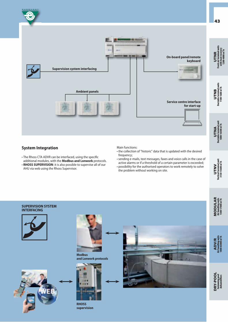
43
UT
NR
Fres
h ai
r ter
min
al u
nits
wit
h he
at re
cove
ry12
00-4
000
m³/h
UT
NB
Duct
able
term
inal
uni
ts11
00-1
680
m³/h
UT
NA
Duct
able
term
inal
uni
t18
00-1
6500
m³/h
UT
NV
Vert
ical
term
inal
uni
t31
50-1
5600
m³/h
MO
DU
LAR
Air h
andl
ing
unit
s 15
00-1
7000
m³/h
DR
Y-P
OO
LSw
imm
ing
pool
dehu
mid
ifi er
s
AD
V/R
Air h
andl
ing
unit
s 10
00-8
3000
m³/h
System Integration
• The Rhoss CTA ADVR can be interfaced, using the specifi c additional modules, with the Modbus and Lonwork protocols.
• RHOSS SUPERVISION: it is also possible to supervise all of our AHU via web using the Rhoss Supervisor.
Main functions: • the collection of "historic" data that is updated with the desired
frequency;• sending e-mails, text messages, faxes and voice calls in the case of
active alarms or if a threshold of a certain parameter is exceeded;• possibility for the authorised operators to work remotely to solve
the problem without working on site.
Supervision system interfacing
Ambient panels
On-board panel/remote keyboard
Service centre interface for start-up
SUPERVISION SYSTEM INTERFACING
RHOSS supervision
Modbusand Lonwork protocols

44
Advance RangeCTA ADV 240÷22920Eurovent Certifi cation
• 5 energy classes to make the right choice
In 2010 Eurovent fi nally introduced an energy classifi cation criterion also for air handling units.The new energy classifi cation will help designers, installers and fi nal users to select the product most suitable for the application.
Parameters taken into consideration• Maximum air speed across the fi ltering section.• Heat recovery effi ciency.• Heat recovery pressure drops.• Absorbed power factor .
Defi nitions of three types of machines1. From A to E for units with 100% recirculation and external
air T >9°C.2. From A to E for units with external air T ≤ 9°C and with partial to
total external air Fresh air.3. From A to E for stand alone extractors.
Immediately identifi able energy effi ciencythe 5 energy classes from A (for the highest energy effi ciency) to E (for the lowest energy effi ciency) off er the best solution for the requested energy effi ciency level, making it a simple and immediate concept.
Globally recognisable Based on a globally recognised standard (EN 13053), Eurovent energy classifi cation for air handling units considers parameters such as air speed, electric power absorbed by the fan motor and the heat recovery effi ciency.
A clear vision requires precisionPrecision is an indispensable requirement for the energy certifi cation of air handling units. Eurovent certifi cation is currently the only European certifi cation program that is able to guarantee this precision through programmed tests and measurements of the certifi ed machines.
CLASS
Maximum speed
Absorbed power factor
Heat recovery(air outlet ≤ 9°C)
m/s fclass-Pref ф % ΔP Pa
A /A/A ≤ 1,8 ≤ 0,90 ≥ 75% ≤ 280
B /B/B ≤ 2,0 ≤ 0,95 ≥ 67% ≤ 230
C /C/C ≤ 2,2 ≤ 1,00 ≥ 57% ≤ 170
D /D/D ≤ 2,5 ≤ 1,06 ≥ 47% ≤ 125
E /E/E ≤ 2,8 ≤ 1,12 ≥ 37% ≤ 100
< E /E/E Unasked

CTA ADVLife Cycle Costs
45
UT
NR
Fres
h ai
r ter
min
al u
nits
wit
h he
at re
cove
ry12
00-4
000
m³/h
UT
NB
Duct
able
term
inal
uni
ts11
00-1
680
m³/h
UT
NA
Duct
able
term
inal
uni
t18
00-1
6500
m³/h
UT
NV
Vert
ical
term
inal
uni
t31
50-1
5600
m³/h
MO
DU
LAR
Air h
andl
ing
unit
s 15
00-1
7000
m³/h
DR
Y-P
OO
LSw
imm
ing
pool
dehu
mid
ifi er
s
AD
V/R
Air h
andl
ing
unit
s 10
00-8
3000
m³/h
RESID
UAL SYSTEM VALUE MAINTENANCE
Considerations regarding Life Cycle Costs for air handling unitsConsiderations regarding LCC are a very powerful instrument for evaluating energy consumption and total operating costs for the air handling units.If used in combination with the energy classifi cation, the customer can be sure to obtain exactly what he expects.
We no longer compare apples and orangesEurovent certifi cation provides a detailed model in order to obtain a clear image of the costs involved with the air handling system and also ensures that the data declared by the manufacturers who participate in the certifi cation program are comparable, exact and accurate.
The calculation takes the following parameters into account:• Air fl ow rate;• Supply temperature in winter and summer;• Thermodynamic functions inside the CTA (heating, cooling,
humidifying, dehumidifying);• Installation location climatic data;• Heat recovery effi ciency;• Energy consumption of the fans;• Operative installation time;• Investment costs;• Energy costs;• Maintenance costs.
LCC analysis and energy classifi cation:an unbeatable combinationThe data from Eurovent certifi ed air handling units can be directly compared and off ers a neutral base for calculating the LCC: in combination with the Eurovent energy classifi cation, the designer, installer and fi nal user obtain clear and precise data that confi rms that they made the right choice.
STARTING INVESTMENT ENERGY COSTS

46
Classifi cation criterion:
Advance RangeCTA ADV 240÷22920Eurovent Certifi cation
EN 1886:1998 EN 1886:2006 Maximum relative
deflection mmxm-1
Resistance to the max pressure
generated by the fan
1B D3 >10 NO
1A D2 10 SI
2A D1 4 SI
EN 1886:1998 EN 1886:2006 Leakage at -400Pa in l/sXm2
3 A - 3,96
A L3 1,32
B L2 0,44
- L1 0,15
EN 1886:1998 EN 1886:2006 Leakage at -700Pa in l/sXm2
3 A - 5,7
A L3 1,9
B L2 0,63
- L1 0,22
• Air leakage through the casing with a depression of 400PaThis is the air leakage of the tested casing at a negative pressure of 400 Pa in relation to the total casing surface.
• Air leakage across the casing with an overpressure of 700 PaThis is the air leakage of the tested casing at a positive pressure of 700 Pa in relation to the total casing surface.
Classification criterion:
• Loss due to filter section bypassThis is air leakage around the filter frame subjected to a negative test pressure of 400Pa and a positive test pressure of 400 Pa.
Classification criterion:
Eurovent certification is synonymous with an absolute guarantee, according to standardised parameters and protocols, of the effective performance of the air handling units. Air handling units in the ADV range brilliantly passed the mechanical and performance tests, confirming the excellence of our product and the seriousness of our commercial offer.
Mechanical performanceVerified according to EN1886: Ventilation for Buildings - Air handling units - Mechanical performanceMore specifically, the following mechanical performance is guaranteed:
• Mechanical resistance of the structureDeflection: the maximum deflection of the unit's sides when subjected to positive or negative pressure, expressed as the difference in distance between a reference plane located outside the unit itself not subjected to pressure and the external surface of the considered surface, subjected or not subjected to the test pressure. This value is an index of unit robustness.
Classification criterion:
EN 1886:1998 EN 1886:2006 Leakage % at-400Pa
6 < F6 G1-F5
4 F6 F6
2 F7 F7
1 F8 F8
0,5 F9 F9

47
UT
NR
Fres
h ai
r ter
min
al u
nits
wit
h he
at re
cove
ry12
00-4
000
m³/h
UT
NB
Duct
able
term
inal
uni
ts11
00-1
680
m³/h
UT
NA
Duct
able
term
inal
uni
t18
00-1
6500
m³/h
UT
NV
Vert
ical
term
inal
uni
t31
50-1
5600
m³/h
MO
DU
LAR
Air h
andl
ing
unit
s 15
00-1
7000
m³/h
DR
Y-P
OO
LSw
imm
ing
pool
dehu
mid
ifi er
s
AD
V/R
Air h
andl
ing
unit
s 10
00-8
3000
m³/h
• Acoustic insulation of the casing
Classifi cation criterion:
Sound pressure measurements are taken around the CTA casing, placing it inside a sound source and repeating the measurements after removing the panels. This provides data regarding the sound reduction provided by the casing.
EN 13053: a European standard for evaluating the energy effi ciency of air handling units.
Characteristic performance measured according to EN13053: Ventilation for Buildings - Air handling units - Rating and performance for units, components and sections.More specifi cally, the following ratings and performance are measured and certifi ed (by independent laboratories) for the air handling units:
• Air fl ow rate• Available static pressure• Absorbed power• Hot water coil heating capacity• Chilled water coil cooling capacity• Coil water side pressure drops• Heat recovery effi ciency• Sound power level measured in the octave band in the outlet and the inlet channel.• Sound power level measured in the octave band measured in the environment.
NOTE: the complete data from the tests performed on the CTA ADV can be found on the website www.eurovent-certifi cation.com in the AHU certifi cation program section.
• Heat transmission of the casingThe global heat exchange coefficient is the quantity of heat transmitted per surface unit of the unit due to the difference in temperature between the inside and the outside of the unit itself.
Classification criterion:
• Casing thermal transfer factorA ratio of the difference between the minimum temperature at any point on the external surface of the unit and the average internal air temperature and the difference of the average air temperature.
Classifi cation criterion:
Class Heat transmission K in W/m²K
T5 No requirement
T4 1,4<U<=2
T3 1<U<=1,4
T2 0,5<U<=1
T1 U<=0,5
Class Kb
TB5 No requirement
TB4 0,3< Kb <=0,45
TB3 0,45< Kb <=0,6
TB2 0,6< Kb <=0,75
Frequency Hz 125 250 500 1000 2000 4000 8000
Noise reduction value dB dB dB dB dB dB dB
• Performance guarantee
• Certain results

48
CTA ADVSELECTION SOFTWARE
• SIMPLE to install and use
• FLEXIBLE when selecting RHOSS units in work conditions
• EFFECTIVE and EXHAUSTIVE results for the designer
• The innovative selection software for the CTA ADV ranges makes it possible to size the unit quickly and correctly. The software easily guides the user through a selection of the confi guration, the components and the accessories for the air handling units. The selection of each individual section can be customised by selecting from among the multiple available accessories.
• The software also has a system that automatically verifi es the input data, which does not permit the insertion of data, sections or accessories that are incompatible with the calculation.
• The software provides professionals with a technical sheet complete with a detailed description and drawing and an up-to-date economic report.
• Each off er we make is stored in a database so a change or economic update can be carried out for the project at any moment.
• The resulting confi guration allows the order to be transmitted directly to the production department, thus considerably reducing the delivery times of the units.
• Our technical sales support can also provide you with a detailed autocad drawing of the unit already during the off er phase, which makes it easier for the designer to check the dimensional constraints of the unit and to insert the drawing already during the initial project phases.

49
UT
NR
Fres
h ai
r ter
min
al u
nits
wit
h he
at re
cove
ry12
00-4
000
m³/h
UT
NB
Duct
able
term
inal
uni
ts11
00-1
680
m³/h
UT
NA
Duct
able
term
inal
uni
t18
00-1
6500
m³/h
UT
NV
Vert
ical
term
inal
uni
t31
50-1
5600
m³/h
MO
DU
LAR
Air h
andl
ing
unit
s 15
00-1
7000
m³/h
DR
Y-P
OO
LSw
imm
ing
pool
dehu
mid
ifi er
s
AD
V/R
Air h
andl
ing
unit
s 10
00-8
3000
m³/h

50
1. Economic bonds
• The selection of an air handling unit must not only be done based on its initial price must also accounting for the costs related to its use. Rhoss helps you minimise these costs thanks to its wide heat recovery range.
• It is estimated that, considering an average life time of 20 years for a tertiary application (the percentages are more unbalanced for industrial plants) the total energy expense to run the air handling system is around 80%.
• If you require maximum effi ciency from your air handling unit during its entire life cycle, you will surely fi nd the system most suitable for you within our off er that integrates the following basic principle: limit energy expenses guaranteeing constant effi ciency and reliability over time.
The life cycle costs of an asset must be understood as the total costs of that asset, for its entire operating life from its purchase to its phasing out, including:
initial investment cost + maintenance cost + energy expenses + fi nal disposal expenses
There are two fundamental reasons for carrying out this type of analysis when selecting an air handling unit: • It provides a decision making tool to help in the most
eff ective selection from among diff erent alternatives;• It provides a benefi t from an environmental point of view
because it minimises a system's energy waste.
Initial investment cost +Maintenance +
Residual system value =
20% =
Energy cost
80%
CONSCIOUSCHOICE
LCC Analysis
Econ
omic
con
stra
ints
Tech
nica
l and
arc
hite
ctur
al c
onst
rain
ts
Advance RangeCTA ADV 240÷22920Energy Savings
GREEN LINE

51
UT
NR
Fres
h ai
r ter
min
al u
nits
wit
h he
at re
cove
ry12
00-4
000
m³/h
UT
NB
Duct
able
term
inal
uni
ts11
00-1
680
m³/h
UT
NA
Duct
able
term
inal
uni
t18
00-1
6500
m³/h
UT
NV
Vert
ical
term
inal
uni
t31
50-1
5600
m³/h
MO
DU
LAR
Air h
andl
ing
unit
s 15
00-1
7000
m³/h
DR
Y-P
OO
LSw
imm
ing
pool
dehu
mid
ifi er
s
AD
V/R
Air h
andl
ing
unit
s 10
00-8
3000
m³/h
2. Selection of the layout and the type of heat recovery to use
• The selection of the type of heat recovery to use is dictated not only by a pure energy/economic choice but also by design and application constraints.
• A quick selection guide is provided below for the heat recovery systems off ered by Rhoss that will be able to meet your application requirements.
Selection of the layout and the type of heat recovery to use
Inlet fan
YES
IntegratedRemote
NO
RRMRAD
RRMRBGRAD
ROT HRAD
ROT SRFI
RRMRBGRAI
Type of heat exchanger
Sensible and latent Sensible
RRM Unidirectional Run around coil heat Recovery
RBG Twinned coil heat recovery
ROT H Rotary heat recovery with a hygroscopic wheel
ROT S Rotary heat recover with sensible wheel
RFI Crossed-fl ow heat recovery
RAD Direct Adiabatic cooling
RAI Indirect Adiabatic heat Recovery

GREENLINE
52
TWINNED COIL HEAT RECOVERYOperating principle• The heat recovery with twinned coils consists in hydraulically
connecting a fi nned coil (in a closed circuit) located on the supply fl ow and one on the exhaust fl ow.
• In this way I have in winter mode a pre-heating of the external air operation, bringing the air entering the hot coil to a higher enthalpic level and in summer mode a free pre-cooling of the external air summer operation, bringing the air entering the cooling coil to a lower enthalpic level. This makes it possible to select a smaller winter heating coil and a smaller summer cooling coil.
• Average effi ciency levels: 45-55%.
Main features• Easy to install. • The system can be installed even if the air inlet and outlet are
far from each other. • Low investment costs.• Low energy consumption (circulation pump).• Medium maintenance costs.• No danger of cross contamination of the air fl ows. Optimal
solution for applications in hospitals/operating rooms, clean rooms…
• Med/low air side pressure drops.
Available options• Exchange coil customisation depending on the required effi ciency
levels (effi ciency and/or pressure drops).• Material customisation depending on the applications: pre-
painted copper/aluminium coils; copper/copper coils; copper/tin-plated copper coils; stainless steel coils.
• In the ADVR range, the twinned heat recovery is provided complete with water circuit and automatic system regulation that always guarantees the maximum energy savings possible.
RUN AROUND THE COIL HEAT RECOVERYOperating principle• The run around the coil run around the coil heat recovery consists
in hydraulically connecting a fi nned coil (in a closed circuit) downstream of the summer cooling coil and another upstream of the coil itself. The two recovery coils are connected together by a water circuit with a pump and regulation valve. This is used to regulate the capacity of the coil downstream of the cold coil, in order to modulate the post-heating request. In this way, it is possible to select a smaller cooling coil size and select a smaller size or even eliminate the summer post-heating coil.
• Average effi ciency levels: 45-55%.
Main features• Easy to install. • Possibility to install the system also without an inlet fan.• Low investment costs.• Low energy consumption (circulation pump).• Medium maintenance costs.• No danger of cross contamination of the air fl ows. Optimal
solution for applications in hospitals/operating rooms, clean rooms…
• Low air side pressure drops.
Available options• Exchange coil customisation depending on the required effi ciency
levels (effi ciency and/or pressure drops).• Material customisation depending on the applications: pre-
painted copper/aluminium coils; copper/copper coils; copper/tin-plated copper coils; stainless steel coils.
• In the ADVR range, the twinned recovery is provided complete with water circuit and automatic system regulation that always guarantees the maximum energy savings possible.
Advance RangeCTA ADV 240÷22920Energy Savings

53
UT
NR
Fres
h ai
r ter
min
al u
nits
wit
h he
at re
cove
ry12
00-4
000
m³/h
UT
NB
Duct
able
term
inal
uni
ts11
00-1
680
m³/h
UT
NA
Duct
able
term
inal
uni
t18
00-1
6500
m³/h
UT
NV
Vert
ical
term
inal
uni
t31
50-1
5600
m³/h
MO
DU
LAR
Air h
andl
ing
unit
s 15
00-1
7000
m³/h
DR
Y-P
OO
LSw
imm
ing
pool
dehu
mid
ifi er
s
AD
V/R
Air h
andl
ing
unit
s 10
00-8
3000
m³/h
CROSSED-FLOW STATIC HEAT RECOVERYOperating principle • The plate heat recovery are static and do not have moving parts.
This guarantees extremely high operating reliability and safety.• The two air fl ows, Fresh air and expulsion, are divided at the
recovery unit inlet into two passages contained between two plates that carry either hot air or cold air.
• These passages are sealed with solutions appropriate for each application, to prevent the possible contamination between the air fl ows. The heat exchange occurs through the plates that make up the passage walls.
• To increase effi ciency, Rhoss uses particular exchangers. The plate surfaces have particular patented "turbulence" design geometries that make it possible to reach effi ciency levels of up to 75%.
Basic features• Low installation and operating costs.• High guarantee of fl ow separation.• No moving parts. • Easy to adapt to any use.• Manufactures with materials suitable for the characteristics
of the diff erent applications. • Low air side pressure drops.• Med/high effi ciency.• Easy to clean and minimum maintenance required.• Eff ective noise muffl ing.• Good quality/price ratio also for small air fl ow rates.
Available options• Extra sealing. To guarantee a better seal between the two air fl ows,
supplementary sealing can be applied on the heat exchanger. This option is recommended in particular applications such as for hospitals, clean rooms, etc.
ROTARY HEAT RECOVERYOperating principle • The air to air rotary heat recoveries used by Rhoss consist
of a cylindrical rotor containing thousands of channels and characterised by a large surface area, are activated by an electric motor that is equipped with a speed regulator, if necessary.
• In rotary heat recovery, the heat exchange takes place due to the accumulation of heat in the rotor. In fact, while the cylinder turns slowly, the expulsion air crosses half of the casing and transfers heat to the rotor matrix, which accumulates it.
• The Fresh air, that crosses the other half, absorbs the accumulated heat. As rotation continues, the parts that absorb and transfer heat are constantly inverted.
• The rotor's rotation speed can be constant or variable through a speed regulator.
• The exchange surface, with is very wide in relation to the volume, permits very high effi ciencies in comparison to other types of heat recoveries, reaching effi ciency levels of up to 85%.
Basic features• The high effi ciency and the possibility to recover both latent
and sensible heat (hygroscopic wheel) makes it possible to signifi cantly reduce a system's installed power
• Possibility to transfer latent heat.• Possible reduction of humidifi cation devices. • Medium pressure drops.• Medium/high investment costs.• Medium/high maintenance costs.• High risk of cross contamination: no air fl ow separation. Not
recommended for hospitals or applications with a high risk of fl ow contamination.
Available options• Hygroscopic treatment. The standard aluminium matrix used for the rotor can be
chemically treated with a potassium carbonate alkaline solution in order to create an oxidated surface that makes the rotor hygroscopic. The oxidation makes the surface porous on a microscopic level, making the transfer of humidity possible between two air currents.
• High effi ciency hygroscopic treatment. The rotor can be provided in special hygroscopic aluminium that
guarantees high performance levels.• Speed regulator. The speed regulator allows the rotation speed control of the
heat recovery, and is installed in the inspection side of the heat recovery near the motor.

GREENLINE
54
Advance RangeCTA ADV 240÷22920Energy Saving
• High summer and winter energy effi ciency
• Plug&Play unit
• Self-adaptive system
• Self-cleaning function
INDIRECT ADIABATIC HEAT RECOVERY Operating principle• To improve the performance in summer mode of the sensible heat
exchangers, the most effi cient solution is to combine them with an indirect adiabatic cooling system (RAI).
• Rhoss has developed an advanced heat recovery system that integrates indirect adiabatic cooling with static, high effi ciency heat recovery. This system makes it possible to signifi cantly cool the expulsed air due to one or more humidifi cation stages, obtaining an outlet air temperature that is lower than the ambient temperature without the use of a cold coil, continuing to recover heat also if the external air temperature is lower than the ambient air. This cooling method is extremely economical and sustainable and makes a substantial resizing of the chiller or even its elimination possible.
Operations during the summer and other hot months• During the hot season, the system automatically activates the
indirect adiabatic humidifi er, which cools the expulsed air before it enters the heat recovery unit. This maximises the temperature diff erence between the expulsed air and the outdoor air, maximising system effi ciency as a result. If required, the controller activates the cooling coil and the post heating coil if necessary to obtain the exact thermohygrometric conditions that were requested.
Operations during winter and other cold months• During winter, the system maintains all of its energy advantages
deriving from its freecooling operation and/or from its substantial heat recovery, guaranteeing maximum energy savings in any environmental condition.
• Based on an enthalpic comparison between outdoor and ambient air and based on the percentage of desired Fresh air, the management system decides on the most economical operation between total free-cooling, partial free-cooling and partial heat recovery or total heat recovery.
• When the machine starts up, the unit will operate in total recirculation conditions in order to achieve the temperature desired as quickly as possible.
Parameters that infl uence system use• The parameters that infl uence the process most are the ambient
temperature and relative humidity and the effi ciency of the heat recovery.
• Also the relative humidity of the outdoor air is important, because at lower humidity levels, the environment can be kept at relatively low humidity levels, improving system eff ectiveness.
• It is important that energy savings evaluations are done based on actual system operating values.
Main features• Compactness, also for large sized machines.• A unit that is self-adaptive to variable air fl ow rates.• Heat recovery system with effi ciency up to 75%.• Minimised air side pressure drops.• Extremely precise regulation components. • Integrated regulation software dedicated to energy
savings.• Plug&Play unit with regulation and integrated fi eld
elements
Available options• Self-cleaning function The advanced recovery system has a self-cleaning ozone
device in order to maintain system effi ciency and prevent the formation of mould, algae and bacteria.
NOTE: to maximise energy savings, RAI is always combined with the use of free-cooling.For more information regarding possible energy savings and the climates in which this system can be best used please contact our technical sales support at Rhoss Spa.

55
UT
NR
Fres
h ai
r ter
min
al u
nits
wit
h he
at re
cove
ry12
00-4
000
m³/h
UT
NB
Duct
able
term
inal
uni
ts11
00-1
680
m³/h
UT
NA
Duct
able
term
inal
uni
t18
00-1
6500
m³/h
UT
NV
Vert
ical
term
inal
uni
t31
50-1
5600
m³/h
MO
DU
LAR
Air h
andl
ing
unit
s 15
00-1
7000
m³/h
DR
Y-P
OO
LSw
imm
ing
pool
dehu
mid
ifi er
s
AD
V/R
Air h
andl
ing
unit
s 10
00-8
3000
m³/h
DIRECT ADIABATIC COOLING Operating principle• Direct adiabatic cooling (RAD) is based on a simple principle:
water in contact with air evaporates spontaneously, taking heat from the air; as a result, the air is cooled and humidifi ed at the same time.
• The power taken from the air is equal to the latent evaporation heat, which is assumed as being equal to 680 W/Kg/h of evaporated water.
• The effi ciency of this type of heat recovery is a direct function of the amount of water evaporated in the unit of time and of the evaporation speed (that is, air water exchange surface).
• Rhoss off ers various adiabatic humidifi cation solutions: with nozzles, evaporative coils (both with or without water recirculation) or with pressurised water sprays depending on the system's energy and water availability.
Parameters that infl uence system use• The outdoor air is cooled by means of water humidifi cation
until reaching a limit value related either to saturation or the obtainment of absolute humidity at the inlet point. Therefore it is the relative humidity of the outdoor air that determines system eff ectiveness: areas with lower humidity are more suited for adiabatic cooling
Main features• Simple installation and integration in the unit.• An inlet fan is not required.• The system can be installed even if the inlet and outlet are
far from each other. • Low or no investment costs (as it uses a humidifi er that is
already foreseen for winter operation).• Low energy consumption.• Medium to low maintenance costs.• This type of recovery increases air humidity, therefore it is
convenient when an adiabatic humidifi er is suitable for the environment.
Available options• Ozone hygenic system Treatment of the evaporator supply water with an ozone system
to prevent the formation of algae, mould, bacteria and viruses (also legionella).
NOTE: to maximise energy savings, RAD is always combined with the use of free-cooling.For more information regarding possible energy savings and the climates in which this system can be best used please contact our technical sales support at Rhoss Spa.

56
Solutions for special applications
The air handling units in the ADV range can be implemented not only for more traditional applications such as in the commercial/hotel/service sector but also for uses in industrial or mission critical sectors.
Thanks to:• the multiple solutions available due to the range of utilised material;• the availability of special components and confi gurations;• the large degree of solution customisation;• the high amount of experience gathered by our design team; • the research studies in the various application sectors developed in the company;• the possibility to test and verify the proposed solutions in the Rhoss R&D Lab.
The range of ADV air handling units is the ideal platform for developing constructive solutions dedicated to the specifi c sectors of application, in compliance with current regulations and guidelines during the implementation phase.
In particular, solutions are developed for:
Units used for applications with elevated requirements for air purity and/or lack of vibrations. Typical applications: laboratories, clean rooms, electronics industry etc.
Units used for industrial applications where must be obtained specifi c room conditions that make it possible to make, or improve, products whose features and quality are infl uenced by ambient air temperature and humidity, so that the manufacturing process can be carried out all year long independently of variations in the outdoor climate. Typical applications: textile, food, pharmaceutical industries, etc.
Units used for applications with particular requirements with regard to the foreseen thermohygrometric treatments, the utilised materials and energy consumption.Typical applications: fi tness centres, indoor pools, spas and wellness centres.
Units used for applications with particular acoustic requirements.Typical applications: recording studios, theatres, concert halls, etc.
Units used in the naval sector with particular requirements regarding the utilised materials, machine dimensions, components corresponding to specifi c industry standards (RINA; DNV).
Advance RangeCTA ADV 240÷22920Special applications

57
UT
NR
Fres
h ai
r ter
min
al u
nits
wit
h he
at re
cove
ry12
00-4
000
m³/h
UT
NB
Duct
able
term
inal
uni
ts11
00-1
680
m³/h
UT
NA
Duct
able
term
inal
uni
t18
00-1
6500
m³/h
UT
NV
Vert
ical
term
inal
uni
t31
50-1
5600
m³/h
MO
DU
LAR
Air h
andl
ing
unit
s 15
00-1
7000
m³/h
DR
Y-P
OO
LSw
imm
ing
pool
dehu
mid
ifi er
s
AD
V/R
Air h
andl
ing
unit
s 10
00-8
3000
m³/h

42
40
63
60
63
60
58
Variable conditions: the fl exibility of our proposal
• In hospital environments and in controlled contamination environments in general, the complexity of the system and the air handling units in particular can vary greatly depending on the type of area requiring air conditioning. The critical zones (such as operating rooms, mortuary rooms, rooms for immunodepressed individuals, analysis laboratories etc.), semi-critical zones (emergency room, hospital rooms, hallways etc.) or non critical zones (offi ces, waiting rooms, etc.) have very diff erent requirements for fi ltration, ventilation and for controlling the thermohygrometric parameters. Rhoss is able to supply the best solution for each of these requirements providing the designer and technical offi ces with all of its experience and professionalism.
• Continued technological evolution and the continuous updating of the reference standard framework require constant replacements to be made to HVAC systems in hospital systems. Our R&D group works constantly in order to off er products that comply with the current regulations and to provide the best technology in the industry.
• There is constant pressure to minimise investment and operating costs for systems while still maintaining or even improving levels of quality, comfort and service. Rhoss is able to off er products that provide great energy savings, making it possible for sanitary system operators to minimise the life cycle cost of the aeraulic systems.
Rhoss's off er for the hospital sector
The ADV health care series was designed according to the directives of the EN13053 standard. All of its components were selected and studied to minimise energy consumption (with particular focus on pressure drops) and maximise the system's overall energetic effi ciency. The following range features only provide an overview of the solutions off ered to the hospital sector and are not meant to represent a design guideline:
STRUCTURE• The machine is completely inspectable due to large access
doors. Each section subjected to frequent maintenance (humidifi er, fi lters, fans) can be supplied with illumination and a large dual pane inspection window, making visual inspections easy.
• The inner structure is completely free of corners or protuberances and only rounded profi les are used. This reduces air friction on the surfaces, the accumulation of dirt or washing liquids inside the unit.
• The material available for the panelling and the structural work guarantee the chemical resistance and bacteriological cleanliness levels required for contamination control.
• The stainless steel condensation collection pans are placed along the entire length of the machine in order to clean all components involved in the fl ow.
FANS AND HUMIDIFIERSThe fan sections can be supplied with diff erent confi gurations depending on specifi c requirements:• Classic belt and pulley fans equipped with an inspection device
and water drain in the envelope to permit its washing. Available in a version with a dual motor or dual complete fan section.
Advance RangeCTA ADV 240÷22920Application: hospital

59
UT
NR
Fres
h ai
r ter
min
al u
nits
wit
h he
at re
cove
ry12
00-4
000
m³/h
UT
NB
Duct
able
term
inal
uni
ts11
00-1
680
m³/h
UT
NA
Duct
able
term
inal
uni
t18
00-1
6500
m³/h
UT
NV
Vert
ical
term
inal
uni
t31
50-1
5600
m³/h
MO
DU
LAR
Air h
andl
ing
unit
s 15
00-1
7000
m³/h
DR
Y-P
OO
LSw
imm
ing
pool
dehu
mid
ifi er
s
AD
V/R
Air h
andl
ing
unit
s 10
00-8
3000
m³/h
• Inverter activated "plug fan" fans for easy and complete cleaning of the sections.
Also available in a version with a dual reserve fan sized between 50 and 100% of the fl ow rate.
• Steam humidifi er with autonomous producer with immersed electrodes/electric/gas heaters.
• Distribution steam nozzles for hospital environments. • For some applications, high pressure adiabatic humidifi ers are
available that make it possible to precisely control ambient humidity without risks for the air salubrity.
• For all humidifi cation sections, the distances between the components are suitable calculated to guarantee proper steam absorption.
• The soundproofi ng sections are equipped with a special protection to prevent the particles from being released during machine operation and therefore pollute the air fl ow.
Innovation at the service of the health industry
Thanks to the synergy created between Rhoss's R&D group and its industrial partners and the possibility to test and validate the various technical solutions in our R&D Lab, we are able to off er a series of innovation solutions in terms of hygenic systems that aim towards reducing the airborne microbic load as much as possible.
• The use of UV germicide lamps: this provides a strong germicidal eff ect through the emission of ultraviolet rays that sterilise the air and the surfaces they reach. Rhoss is able to maximise the germicidal eff ect of the rays by using an extremely refl ective installation surface and by carefully studying the best position within the CTA.

60
Advance RangeCTA ADV 240÷22920Higyenical Air Treatment
HIGYENICAL AIR TREATMENT:patented system for ADV Rhoss AHUs sanitation
From the exclusive technical partnership among vergreen Tecno-plants and Rhoss has born Hygienical Air Treatment System (HAT). Thanks to H.A.T. Rhoss widens the traditional concept of air treatment , founded on the classical vision of control of air temperature and humidity parameters, introducing a third variable: the control and reduction of the microbiological risk of contamination.The use of this technology in AHUs, contributes actively to resolve an issue that generally aff ects the whole HVAC system.From this new concept of air treatment comes out the need of an integrated product able to combine the thermodynamic performance of the unit with the advanced indoor Air Quality control.In this optic borns the technical partnership that led to the development of Hygienical Air Treatment System among Rhoss and Evergreen Tecno-plants, an Italian company leader in the market of the ozone sanitation systems. This technology has been used for several years and with considerable success in the Agro-foodstuff process industry and in the swimming pools.
Ozone (allotropic state of oxygen) is an unstable gas composed of trivalent oxygen (O3) that does not leave any trace of chemical residue. Its elevated oxidizing power and its natural tendency to return to oxygen (O2) make it a product with high usage potential in many applications for air treatment as the microbiological contamination control and the deodorization.In nature it is the element with the strongest oxidation power, after fl uorine, with 2,07 V, and works oxidizing the cell’s membrane which is the main target of its antimicrobial action.
Some of the most important advantages achievable with the Hygienical Air Treatment system
• Elimination and/or inactivation of bacteria, moulds, viruses, spore from all the surfaces, even those diffi cult to reach with other cleaning systems (as fi lters, inner side of coils…)
• Possibility to implement the system in adiabatic humidifi ers both in the existing units and in new installations off ering an interesting cost-benefi t balance.
• Self sanitation of AHU.• Elimination of undesired odours from the environment.• Reduction of the environmental impact of industries (ISO 14000,
EMAS).• Higher effi ciency of heat exchange coils and of the unit on the
whole due to the absence of bacteria and moulds proliferation.• Optimization of the sanitation protocols and compliance with
Legislative Decree no. 81, 30/04/2008.

61
UT
NR
Fres
h ai
r ter
min
al u
nits
wit
h he
at re
cove
ry12
00-4
000
m³/h
UT
NB
Duct
able
term
inal
uni
ts11
00-1
680
m³/h
UT
NA
Duct
able
term
inal
uni
t18
00-1
6500
m³/h
UT
NV
Vert
ical
term
inal
uni
t31
50-1
5600
m³/h
MO
DU
LAR
Air h
andl
ing
unit
s 15
00-1
7000
m³/h
DR
Y-P
OO
LSw
imm
ing
pool
dehu
mid
ifi er
s
AD
V/R
Air h
andl
ing
unit
s 10
00-8
3000
m³/h
Application Sectors
• Public communities (Collages, schools, barracks)• Tertiary plants with high infl ux of people ( shopping centres,
cinemas, meeting rooms)• Hospitals, operating theatres, doctor’s offi ces, clinics, labs.• Swimming pools, public sport/fi tness centres, spas.• Pharmaceutical, agro-foodstuff s, chemical industry.• Wine industry.
Hygienical air treatment can be installed:• In ADVR plug and play units with factory fi tted electronic control• In ADV units where the control system is supplied by a third part company.All the HAT system components are installed inside a technical compartment in the AHU and completely integrated in the unit.
System Description
H.A.T is a patented at European level system integrated in our AHUs. It saturate the inside of the unit acting uniformly on all components (coils ,fi lters, fans, housing) being active also in the most narrow zones unreachable from other systems currently in use. The inactivation of bacteria, moulds, yeasts, parasites and viruses occurs also at low ozone concentrations and with short contact times through the complete control of the oxidizing power of ozone itself. The management is done completely automatically by the electronic control that via the O3 air sensor detection is able to modulate, manage and control the entire cycle.
Sanitation cycle
The sanitation cycle can be divided into three phases: Phase 1: ozone generation.Phase 2: control and maintenance of the Set Point Level.Phase 3: catalyst that ensures the complete conversion of ozone into oxygen.
It’s important to note that in the fi rst phase ozone is not generated through under pressure systems or gas cylinders that require storage and disposal, but, thanks to the technology we use, is generated on site using directly the oxygen available in ambient air in which the unit is located.
PHASE 1
PHASE 2
PHASE 3
Ozone Injection
Ozone Injection
Ozone Injection
Concentration measuring probe
Concentration measuring probe
Concentration measuring probe = Component Off /Closed. = Component On/activated.

Web code: DRY-POOL DRP1 DAFC-DAHR DRP2
62
Dry-Pool RangeDAESY-DRESY-DTESY-DEESY 108÷2140Dehumidifi cation capacity: 8-140 l/h
• R410A
• Built-in regulation
• Sandwitch Panels
• Profi les with thermal cut
Air and/or water-cooled SWIMMING POOL DEHUMIDIFIERS with centrifugal fans. Range with hermetic Scroll compressors and R410A refrigerant gas.
Construction features • Frame and load-bearing structure: extruded, thermally cut
aluminium sections of 40 x 40 mm with concealed screws. Balloon type gasket fi tted into the profi le. Aluminium base.
• Panelling: 25 mm thick, in double sheet metal (galvanised steel interior, pre-coated exterior RAL 9002). Hot injected polyurethane insulation (average density 40 Kg/m³).
• Compressor: hermetic, rotary scroll compressor, complete with thermal protection and crankcase heater.
• Evaporating coil: copper pipes and fi ns with condensation collection pan.
• Condensing coil: copper pipes and aluminium fi ns.• Water side heat exchanger (DRESY-DTESY-DEESY): brazed plates in
special stainless steel for chlorinated water or shell and tube in Cu/Ni for water treated with salt chlorination. DEESY models have a stainless steel brazed plate exchanger unsuitable for use with chlorinated water. Water fl ow diff erential pressure switch.
• Fan: centrifugal, double suction with external motor and belt transmission with variable pulleys. Standard installation with vertical air supply. Available static pressure of 100 Pa.
• Filters: class G3 installed internally on the inlet. • Refrigerant circuit: separate from the aeraulic circuit and
complete with dryer fi lter, sight glass, high and low pressure gas gauges, charge connections, high and low pressure side safety pressure switch, thermostatic expansion valve, liquid receiver (version DRESY-DTESY-DEESY), high pressure safety valve, R410A refrigerant charge.
• Electrical panel: prepared for 230V-1ph+N-50Hz power supply (mod. 108 single-phase) and 400V-3ph+N-50Hz power supply (mod. 108 -2140 three-phase). Complete with power supply isolating switch with door lock safety device, thermal overload switches, power contactors, protection fuses on the auxiliary circuit and microprocessor electronic control card.
Versions • DAESY: dehumidifi er with 100% heat exchange on swimming pool
air side• DRESY: dehumidifi er with 45% heat recovery on Swimming pool
side. • DTESY: dehumidifi er with 100% heat recovery on Swimming pool
side• DEESY: dehumidifi er with 100% heat recovery on Swimming pool
side and the possibility of 100% heat exchange on the external dry-cooler.
Versions:• EXT - For outdoor installations.• USCO-A - Inlet side horizontal air outlet.• USCO-B - Side opposite of the inlet horizontal air outlet.
Factory fi tted accessories• Auxiliary hot water coil (BA) with copper pipes and aluminium fi ns,
complete with regulation and three-way valve.• Auxiliary hot water coil (BA) with copper pipes and pre-painted
aluminium fi ns, complete with regulation and three-way valve.• Auxiliary hot water coil (BA) with copper pipes and fi ns, complete
with regulation and three-way valve.• Technical compartment for external hydraulic housing and
regulation of the auxiliary hot water coil.• Condensation coil with copper pipes and pre-painted aluminium
fi ns.• Condensation coil with copper pipes and fi ns.• Auxiliary electrical coil as an alternative to the hot water coil,
complete with shuttered regulation.• Supply fan with available static pressure of 150 Pa.• Supply fan with available static pressure of 200 Pa.• Supply fan treated with epoxy paint.
Accessories supplied loose• Water fi lter.
Accessories supplied loose for standard control• RS 485 serial interface.• Serial converter RS485/USB.

63
UT
NR
Fres
h ai
r ter
min
al u
nits
wit
h he
at re
cove
ry12
00-4
000
m³/h
UT
NB
Duct
able
term
inal
uni
ts11
00-1
680
m³/h
UT
NA
Duct
able
term
inal
uni
t18
00-1
6500
m³/h
UT
NV
Vert
ical
term
inal
uni
t31
50-1
5600
m³/h
MO
DU
LAR
Air h
andl
ing
unit
s 15
00-1
7000
m³/h
DR
Y-P
OO
LSw
imm
ing
pool
dehu
mid
ifi er
s
AD
V/R
Air h
andl
ing
unit
s 10
00-8
3000
m³/h
Accessories supplied loose for advanced control• Remote keyboard with display. • RS 485 serial interface.• FTT10 serial interface.• Serial converter RS485/USB.
ADDITIONAL MODULES• DAFC - Free-cooling module.• DAHR - Crossed-fl ow static heat recovery module.
Construction features • Frame and load-bearing structure: extruded, thermally cut
aluminium sections of 40 x 40 mm with concealed screws. Balloon type gasket fi tted into the profi le. Aluminium base.
• Panelling: 25 mm thick double sheet metal (galvanised steel interior, pre-painted exterior RAL 9002). Hot injected polyurethane insulation (average density 45 Kg/m³).
• Fan: centrifugal, double suction with external motor and belt transmission with variable pulleys. Standard installation with horizontal air inlet. Available static pressure of 100 Pa.
• Dampers: motorised aluminium dampers with actuators.• Control: electronic microprocessor control for managing the
dehumidifi er and additional module assembly by means of energy-saving management logic.
Versions:• EXT - For outdoor installations.
Factory fi tted accessories• Inlet fan with available static pressure of 150 Pa.• Inlet fan with available static pressure of 200 Pa.• Inlet fan treated with epoxy paint.
DRESY/DTESY/DEESY
Swimming pool water
DRESY/DTESY/DEESY+BA
boiler
Swimming pool water
DAESY
SUPPLY AIR
RETURN AIR
RETURN AIR
RETURN AIR
SUPPLY AIR
SUPPLY AIR

M
M M
– + +
+ M
M
M M
MM
M M
M M
– + +
+M
M
MM
M M
M
M M
– + +
+ M
M
M M
MM
M M
64
Dry-Pool RangeDAESY-DRESY-DTESY-DEESY 108÷2140Combination examples between the dehumidifi er and additional module
Pool water circuit
SUPPLY AIR DRYCOOLER
Boiler
PoolRETURN AIR
Exhaust air
DRESY/DTESY + BA + DAFC
Pool water circuit
SUPPLY AIR
Boiler
PoolRETURN AIR
Exhaust air Fresh air
DRESY/DTESY + BA + DAHR
Pool water circuit
SUPPLY AIR
Boiler
PoolRETURN AIR
Exhaust airFresh air
Fresh air
DEESY + BA + DAHR
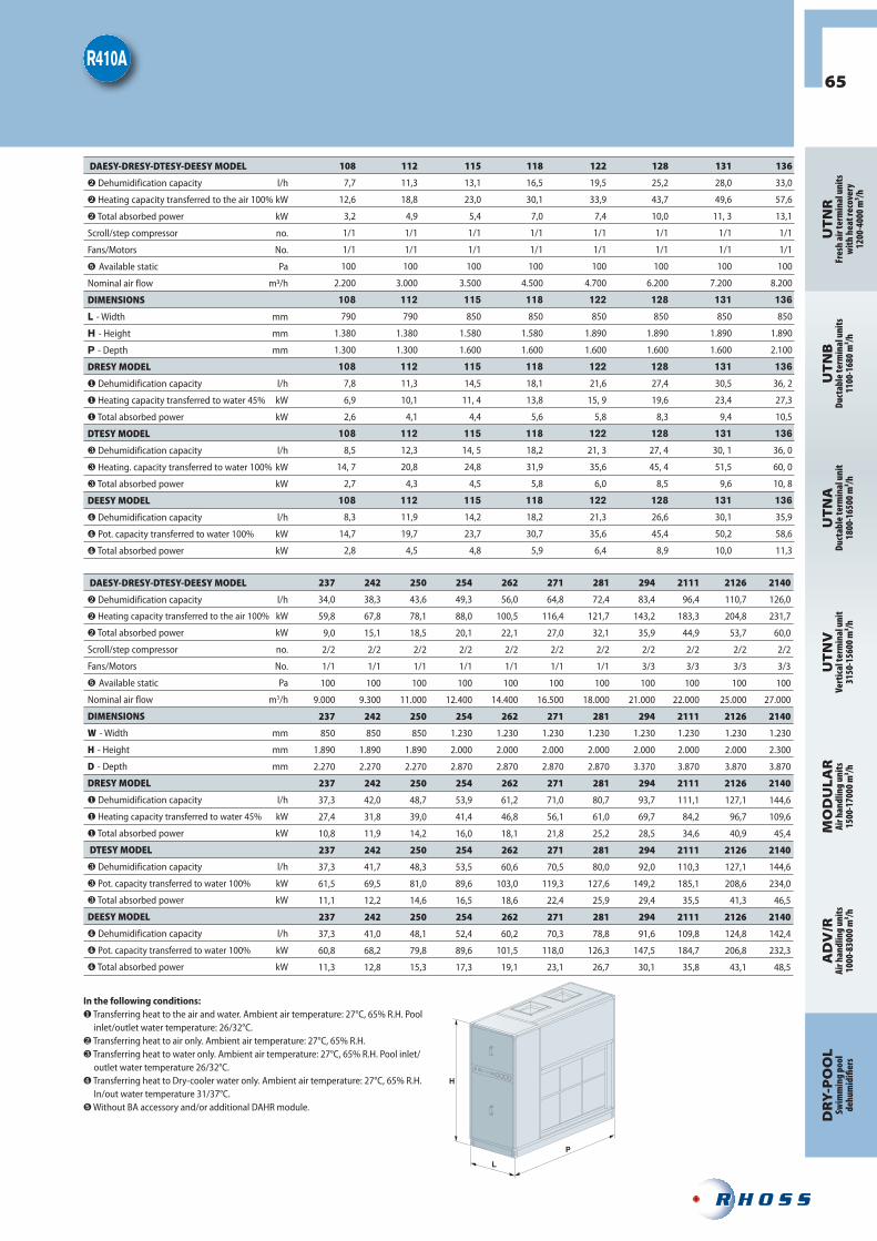
H
L
P
65
UT
NR
Fres
h ai
r ter
min
al u
nits
wit
h he
at re
cove
ry12
00-4
000
m³/h
UT
NB
Duct
able
term
inal
uni
ts11
00-1
680
m³/h
UT
NA
Duct
able
term
inal
uni
t18
00-1
6500
m³/h
UT
NV
Vert
ical
term
inal
uni
t31
50-1
5600
m³/h
MO
DU
LAR
Air h
andl
ing
unit
s 15
00-1
7000
m³/h
DR
Y-P
OO
LSw
imm
ing
pool
dehu
mid
ifi er
s
AD
V/R
Air h
andl
ing
unit
s 10
00-8
3000
m³/h
108 112 115 118 122 128 131 136
7,7 11,3 13,1 16,5 19,5 25,2 28,0 33,0
12,6 18,8 23,0 30,1 33,9 43,7 49,6 57,6
3,2 4,9 5,4 7,0 7,4 10,0 11, 3 13,1
1/1 1/1 1/1 1/1 1/1 1/1 1/1 1/1
1/1 1/1 1/1 1/1 1/1 1/1 1/1 1/1
100 100 100 100 100 100 100 100
2.200 3.000 3.500 4.500 4.700 6.200 7.200 8.200
108 112 115 118 122 128 131 136
790 790 850 850 850 850 850 850
1.380 1.380 1.580 1.580 1.890 1.890 1.890 1.890
1.300 1.300 1.600 1.600 1.600 1.600 1.600 2.100
108 112 115 118 122 128 131 136
7,8 11,3 14,5 18,1 21,6 27,4 30,5 36, 2
6,9 10,1 11, 4 13,8 15, 9 19,6 23,4 27,3
2,6 4,1 4,4 5,6 5,8 8,3 9,4 10,5
108 112 115 118 122 128 131 136
8,5 12,3 14, 5 18,2 21, 3 27, 4 30, 1 36, 0
14, 7 20,8 24,8 31,9 35,6 45, 4 51,5 60, 0
2,7 4,3 4,5 5,8 6,0 8,5 9,6 10, 8
108 112 115 118 122 128 131 136
8,3 11,9 14,2 18,2 21,3 26,6 30,1 35,9
14,7 19,7 23,7 30,7 35,6 45,4 50,2 58,6
2,8 4,5 4,8 5,9 6,4 8,9 10,0 11,3
237 242 250 254 262 271 281 294 2111 2126 2140
34,0 38,3 43,6 49,3 56,0 64,8 72,4 83,4 96,4 110,7 126,0
59,8 67,8 78,1 88,0 100,5 116,4 121,7 143,2 183,3 204,8 231,7
9,0 15,1 18,5 20,1 22,1 27,0 32,1 35,9 44,9 53,7 60,0
2/2 2/2 2/2 2/2 2/2 2/2 2/2 2/2 2/2 2/2 2/2
1/1 1/1 1/1 1/1 1/1 1/1 1/1 3/3 3/3 3/3 3/3
100 100 100 100 100 100 100 100 100 100 100
9.000 9.300 11.000 12.400 14.400 16.500 18.000 21.000 22.000 25.000 27.000
237 242 250 254 262 271 281 294 2111 2126 2140
850 850 850 1.230 1.230 1.230 1.230 1.230 1.230 1.230 1.230
1.890 1.890 1.890 2.000 2.000 2.000 2.000 2.000 2.000 2.000 2.300
2.270 2.270 2.270 2.870 2.870 2.870 2.870 3.370 3.870 3.870 3.870
237 242 250 254 262 271 281 294 2111 2126 2140
37,3 42,0 48,7 53,9 61,2 71,0 80,7 93,7 111,1 127,1 144,6
27,4 31,8 39,0 41,4 46,8 56,1 61,0 69,7 84,2 96,7 109,6
10,8 11,9 14,2 16,0 18,1 21,8 25,2 28,5 34,6 40,9 45,4
237 242 250 254 262 271 281 294 2111 2126 2140
37,3 41,7 48,3 53,5 60,6 70,5 80,0 92,0 110,3 127,1 144,6
61,5 69,5 81,0 89,6 103,0 119,3 127,6 149,2 185,1 208,6 234,0
11,1 12,2 14,6 16,5 18,6 22,4 25,9 29,4 35,5 41,3 46,5
237 242 250 254 262 271 281 294 2111 2126 2140
37,3 41,0 48,1 52,4 60,2 70,3 78,8 91,6 109,8 124,8 142,4
60,8 68,2 79,8 89,6 101,5 118,0 126,3 147,5 184,7 206,8 232,3
11,3 12,8 15,3 17,3 19,1 23,1 26,7 30,1 35,8 43,1 48,5
DAESY-DRESY-DTESY-DEESY MODEL
Dehumidification capacity l/h
Heating capacity transferred to the air 100% kW
Total absorbed power kW
Scroll/step compressor no.
Fans/Motors No.
Available static Pa
Nominal air flow m/h
DIMENSIONS
L - Width mm
H - Height mm
P - Depth mm
DRESY MODEL
Dehumidification capacity l/h
Heating capacity transferred to water 45% kW
Total absorbed power kW
DTESY MODEL
Dehumidification capacity l/h
Heating. capacity transferred to water 100% kW
Total absorbed power kW
DEESY MODEL
Dehumidification capacity l/h
Pot. capacity transferred to water 100% kW
Total absorbed power kW
DAESY-DRESY-DTESY-DEESY MODEL
Dehumidification capacity l/h
Heating capacity transferred to the air 100% kW
Total absorbed power kW
Scroll/step compressor no.
Fans/Motors No.
Available static Pa
Nominal air flow m3/h
DIMENSIONS
W - Width mm
H - Height mm
D - Depth mm
DRESY MODEL
Dehumidification capacity l/h
Heating capacity transferred to water 45% kW
Total absorbed power kW
DTESY MODEL
Dehumidification capacity l/h
Pot. capacity transferred to water 100% kW
Total absorbed power kW
DEESY MODEL
Dehumidification capacity l/h
Pot. capacity transferred to water 100% kW
Total absorbed power kW
In the following conditions: Transferring heat to the air and water. Ambient air temperature: 27°C, 65% R.H. Pool inlet/outlet water temperature: 26/32°C.
Transferring heat to air only. Ambient air temperature: 27°C, 65% R.H. Transferring heat to water only. Ambient air temperature: 27°C, 65% R.H. Pool inlet/outlet water temperature 26/32°C.
Transferring heat to Dry-cooler water only. Ambient air temperature: 27°C, 65% R.H. In/out water temperature 31/37°C.
Without BA accessory and/or additional DAHR module.

66
DRY-POOLSELECTION SOFTWARE
FROM THE SYSTEM…• Air conditioning for an indoor pool has very diff erent requirements in comparison to a typical system for residential or commercial users.
• In order to make the sizing of these systems easier, Rhoss has created a selection program that can be used to accurately calculate the rate of evaporation generated in these particular environments.
• All of the fundamental parameters necessary for determining the work load of the dehumidifi er are
entered in the calculation tool. These parameters include the temperature and relative humidity of the air in the room, pool surface area, water temperature and occupation rate.
• To make the selection more accurate, also other elements are considered such as the number of pools and their water volume, the cubage of the room, the number of spectators as well as the presence of special water games.

67
UT
NR
Fres
h ai
r ter
min
al u
nits
wit
h he
at re
cove
ry12
00-4
000
m³/h
UT
NB
Duct
able
term
inal
uni
ts11
00-1
680
m³/h
UT
NA
Duct
able
term
inal
uni
t18
00-1
6500
m³/h
UT
NV
Vert
ical
term
inal
uni
t31
50-1
5600
m³/h
MO
DU
LAR
Air h
andl
ing
unit
s 15
00-1
7000
m³/h
DR
Y-P
OO
LSw
imm
ing
pool
dehu
mid
ifi er
s
AD
V/R
Air h
andl
ing
unit
s 10
00-8
3000
m³/h
…TO THE DEHUMIDIFIER.• The results provided by the calculation are indispensable references for selecting the most suitable dehumidifi er size for guaranteeing comfort and safety of the entire system.
• The user is guided until the unit confi guration page where all DRY-POOL versions (DAESY, DRESY, DTESY, DEESY) can be selected, together with the wide range of available options and accessories.


20
11
AIR HANDLINGSYSTEMSProduct CatalogueRHOSS S.P.A. Via Oltre Ferrovia, 32 - 33033 Codroipo (UD) - Italytel. +39 0432 911611 - fax +39 0432 [email protected] - www.rhoss.it - www.rhoss.com
IR GROUP S.A.S.U.19, chemin de la Plaine - 69390 Vourles - Francetél. +33 (0)4 72 31 86 31 - fax +33 (0)4 72 31 86 [email protected]
RHOSS Deutschland GmbHHölzlestraße 23, D-72336 Balingen, OT Engstlatt - Germanytel. +49 (0)7433 260270 - fax +49 (0)7433 [email protected] - www.rhoss.de
Italy branch offi ces:Codroipo (UD)33033 Via Oltre Ferrovia, 32tel. +39 0432 911611 - fax +39 0432 911600
Agrate Brianza (MI)20041 Centro Colleoni - Palazzo Taurus, 1tel. +39 039 6898394 - fax +39 039 6898395
La R
HO
SS S
.P.A
. dec
lines
all
resp
on
sib
ility
for p
oss
ible
mis
take
s in
th
is d
ocu
men
t an
d re
serv
es t
he
righ
t to
alte
r th
e fe
atu
res
of t
hei
r pro
du
cts
with
ou
t n
otic
e.
Rhoss is involved in the Eurovent certifi cation programme.The products in question are included in the guide to Eurovent certifi ed products, which can be found at www.eurovent-certifi cation.com
K1
70
11
EN
_20
11
20
00 -
Prin
ted
: Gra
fi ch
e Vi
anel
lo