Embed Size (px)
Citation preview
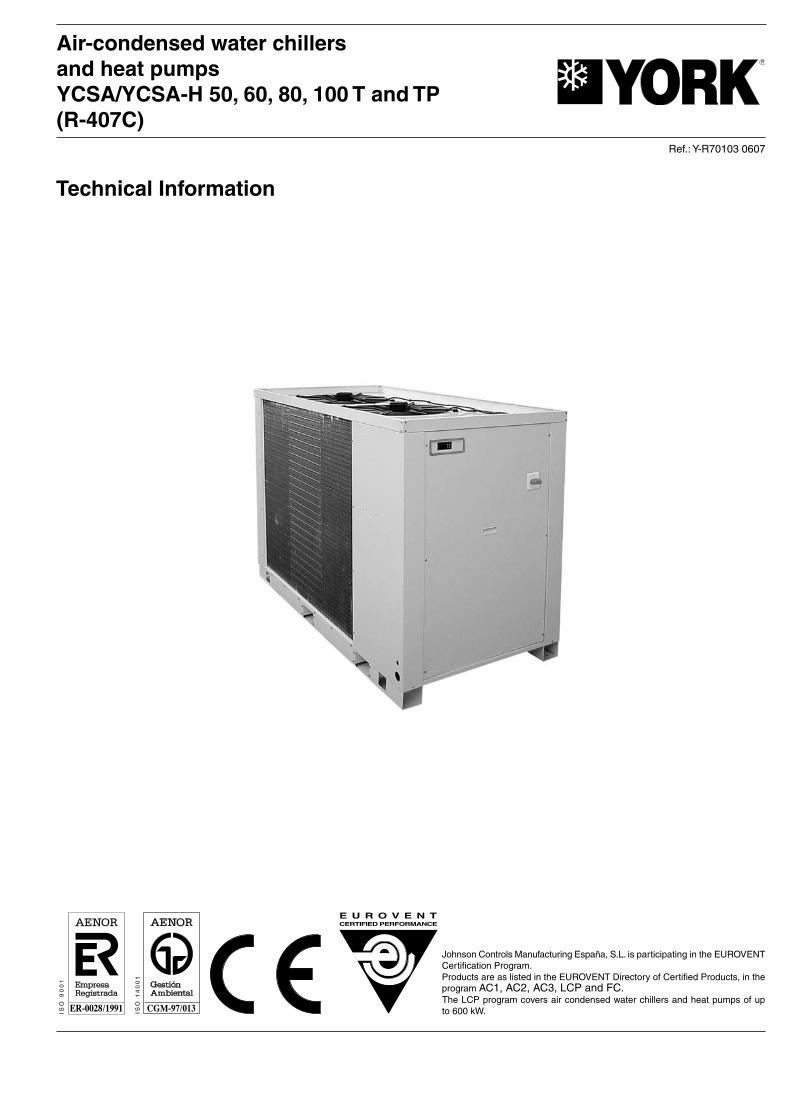
Johnson Controls Manufacturing España, S.L. is participating in the EUROVENT Certification Program.Products are as listed in the EUROVENT Directory of Certified Products, in the program AC1, AC2, AC3, LCP and FC.The LCP program covers air condensed water chillers and heat pumps of up to 600 kW.
� � � � � � � ����������������������
�������������
������
���������������
�����
Technical Information
Air-condensed water chillers and heat pumps YCSA/YCSA-H 50, 60, 80, 100 T and TP(R-407C)
Ref.: Y-R70103 0607


3
Index
General information 5
- General description 5- Nomenclature 5- Models available and capacities 5- Features and advantages 6
Technical Specifications 6
- Accesories and options 7- Physical data, cool only units 8- Physical data, heat pump units 9- Units without Pack 10- Operation, cooling and hydraulic diagram, cool only unit 11- Operation, cooling and hydraulic diagram, heat pump unit 12- Table 1. Cooling capacities YCSA 13- Table 2. Cooling capacities YCSA, 35% ethylene glycol 14- Table 3. Correcting factors for other glycol concentrations 14- Table 4. Cooling capacities YCSA-H 15- Table 5. Heating capacities YCSA-H 15- Table 6. Available pressure for the hydraulic circuit 16- Table 7. Pressure drop in the hydraulic circuit 16- Table 8. Pressure drop filters 17
Selection guide YCSA and YCSA-H 17
- Necessary information 17- Selection guide with glycol 18 - 20- Sound power spectrum 20
Installation Instructions 21
- Inspection 21- Environmental protection 21
Page Page
- Elimination of the unit 21- Safety 21- Transportation 21- Handling 21- Warming signs 21- Location 22- Fastening the unit 22- Clearances 22
Wiring 22
- Electrical connections 22- Scroll compressors, rotational direction 22- Hydraulic connections 22- Dimensions and hydraulic connections 23 - 24- Minimum technical clearance 25- Wiring diagram 26 - 28- Wiring 29- Electrical characteristics 30- Limits of use 30- Prior to final approval of the installation 30
Operating instructions µC2 + Expansion (Rev.1015) 31
- Unit description 31- Standard components 31- General diagram 32- Symbols on the display 33- Functions related to the control buttons 33- Location of controls 34- Parameter tables 34 - 44
Accessories 45 - 50


5
YCSA 60 T P E2
Air/water water chiller withaxial fans
Approximate cooling capacity in kW
Voltage (400.3.50)
With Hydro Kit (Pack)
Edition
YCSA-H 60 T P E2
Air/water heat pump withaxial fans
Approximate cooling capacity in kW
Voltage (400.3.50)
With Hydro Kit (Pack)
Edition
General InformationGeneral descriptionThe YCSA/YCSA-H 50, 60, 80 and 100 units are high-per-formance air-water water chillers and heat pumps using R-407C ecological refrigerant.These units are designed for air conditioning or industrial ap-plications that require cold or hot water. They are silent and compact units, equipped with vertical air discharge axial fans, that can be installed directly outdoors. They are available in two Versions: with and without a Hydro Kit, which includes a buffer tank and a high head pressure pump.The control system of these units is a specially programmed electronic controller to be used on air-water water chillers and heat pumps equipped with tandem compressors.Easy to use and safe, these units precision control the water return temperature of the installation, carry out defrost cycles, modulate fan speeds and control compressor, pump and electric heater start-ups. By reading the control probes and safety elements, the controller protects the entire equipment against malfunctions. The system allows connecting the unit to a standard RS485 monitoring network. For further informa-tion, please see Operating Instructions.The YCSA/YCSA-H 50, 60, 80 and 100 units are made of proven quality components and manufactured in compliance with standards in force (ISO 9001 certification).
Nomenclature
Cooling capacities in kW for 12/7° C entering/leaving water temperature, and 35° C ambient temperature.
Heating capacities in kW for 40/45° C entering/leaving water temperature, and 7° C ambient temperature.
Models available and capacities
Cooling capacity
Heating capacity
Heat pump model YCSA-H YCSA-H YCSA-H YCSA-H 50 60 80 100
45.4 65.3 74.3 90
54.4 62.5 81.2 101
Cool only model YCSA YCSA YCSA YCSA 50 60 80 100
49.2 61.2 78.6 96Cooling capacity
Nomenclature
6
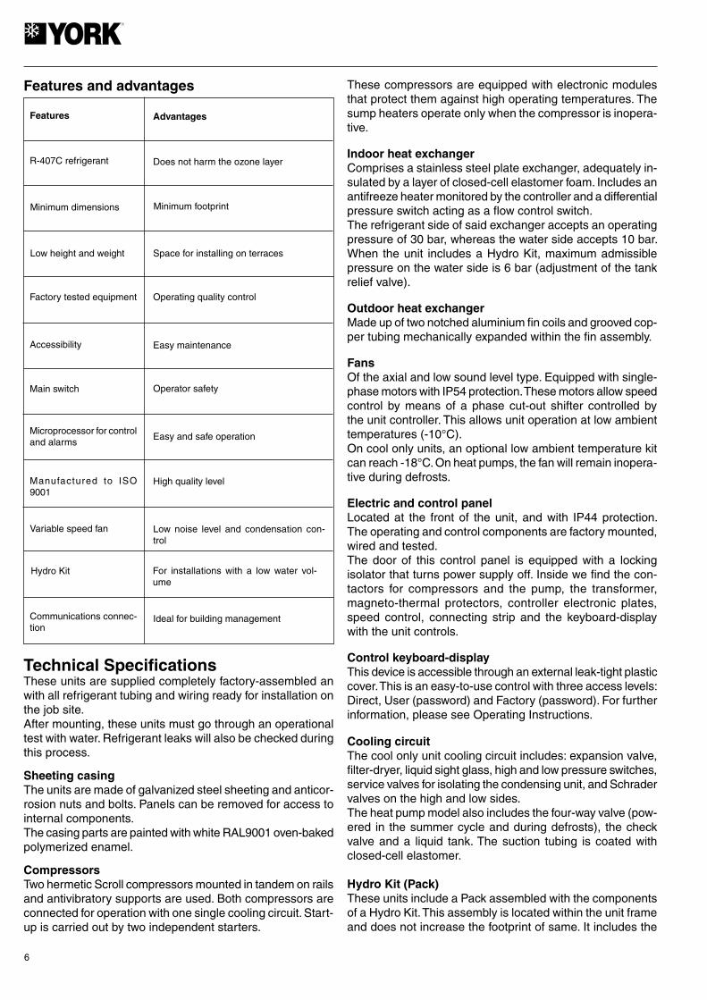
Features and advantages These compressors are equipped with electronic modules that protect them against high operating temperatures. The sump heaters operate only when the compressor is inopera-tive.
Indoor heat exchangerComprises a stainless steel plate exchanger, adequately in-sulated by a layer of closed-cell elastomer foam. Includes an antifreeze heater monitored by the controller and a differential pressure switch acting as a flow control switch. The refrigerant side of said exchanger accepts an operating pressure of 30 bar, whereas the water side accepts 10 bar. When the unit includes a Hydro Kit, maximum admissible pressure on the water side is 6 bar (adjustment of the tank relief valve).
Outdoor heat exchangerMade up of two notched aluminium fin coils and grooved cop-per tubing mechanically expanded within the fin assembly.
FansOf the axial and low sound level type. Equipped with single-phase motors with IP54 protection. These motors allow speed control by means of a phase cut-out shifter controlled by the unit controller. This allows unit operation at low ambient temperatures (-10°C). On cool only units, an optional low ambient temperature kit can reach -18°C. On heat pumps, the fan will remain inopera-tive during defrosts.
Electric and control panelLocated at the front of the unit, and with IP44 protection. The operating and control components are factory mounted, wired and tested. The door of this control panel is equipped with a locking isolator that turns power supply off. Inside we find the con-tactors for compressors and the pump, the transformer, magneto-thermal protectors, controller electronic plates, speed control, connecting strip and the keyboard-display with the unit controls.
Control keyboard-displayThis device is accessible through an external leak-tight plastic cover. This is an easy-to-use control with three access levels: Direct, User (password) and Factory (password). For further information, please see Operating Instructions.
Cooling circuitThe cool only unit cooling circuit includes: expansion valve, filter-dryer, liquid sight glass, high and low pressure switches, service valves for isolating the condensing unit, and Schrader valves on the high and low sides. The heat pump model also includes the four-way valve (pow-ered in the summer cycle and during defrosts), the check valve and a liquid tank. The suction tubing is coated with closed-cell elastomer.
Hydro Kit (Pack)These units include a Pack assembled with the components of a Hydro Kit. This assembly is located within the unit frame and does not increase the footprint of same. It includes the
Technical SpecificationsThese units are supplied completely factory-assembled an with all refrigerant tubing and wiring ready for installation on the job site. After mounting, these units must go through an operational test with water. Refrigerant leaks will also be checked during this process.
Sheeting casingThe units are made of galvanized steel sheeting and anticor-rosion nuts and bolts. Panels can be removed for access to internal components. The casing parts are painted with white RAL9001 oven-baked polymerized enamel.
CompressorsTwo hermetic Scroll compressors mounted in tandem on rails and antivibratory supports are used. Both compressors are connected for operation with one single cooling circuit. Start-up is carried out by two independent starters.
Manufactured to ISO 9001
High quality level
Features Advantages
Accessibility Easy maintenance
Main switch Operator safety
Variable speed fan Low noise level and condensation con-trol
R-407C refrigerant Does not harm the ozone layer
Minimum dimensions Minimum footprint
Microprocessor for control and alarms
Easy and safe operation
Hydro Kit For installations with a low water vol-ume
Communications connec-tion
Ideal for building management
Low height and weight Space for installing on terraces
Factory tested equipment Operating quality control

7
following components: Lined buffer tank with an antifreeze heater, centrifugal pump, expansion vessel charged with nitrogen at 1.5 bar, relief valve set to 6 bar, water circuit pres-sure gauge, two air bleed valves, filling valve and drain valve. Also includes a mesh filter for the water circuit. This filter is supplied loose for installation at the most con-venient point.
Protecting gridsTo protect the coils from possible impacts. Made of steel sheeting and painted with oven baked polymerized white enamel (RAL9001).
Accessories and optionsUnit without Hydro KitIncludes the elements described in the previously mentioned specifications, less the Hydro Kit (Pack). The water circuit includes an air bleed valve. Connections are ready for field installation.
Dual pumpAccessory available on models YCSA-80 and 100 with hydro kit. The second pump starts upon activation of the heat switch of the first pump.
Flow switchFor field installation. Insures sufficient water circulation when the unit is in operation.
Anticorrosion protection of finsTwo options are available:- Aluminium fins with Blue Fin primer.- Copper fins.
Water filter (2" and 2 1/2")Supplied as a standard element on units including the Hydro Kit (Pack).Stainless steel screen with 1 mm. diameter perforations.Optional on units not including the Pack.The warrantee of the unit will not be valid if a water filter has not been installed.
Remote control unitWall-mounted remote control unit with keyboard for cool/heat and ON/OFF functions. Includes power supply, alarm and cool/heat LEDs. Maximum cable length: 50 m.
Remote terminalFor total access and control of the system by means of the display and buttons. Allows selecting cool, heat and off functions. Can also modify operating parameters and moni-tor the system. Can be installed at a maximum distance of 1040 m.
BMS connectionsBy means of a serial board, it is possible to connect the system to a standard RS485 monitoring network.
Low ambient temperature kitIncludes two pressure transducers for controlling condensing pressure at low ambient temperature (-18°C). Available for cool only units only.
Low noise level (LN) unitsThese include anti-noise casings mounted on the compres-sors and sound insulation lining the panels of the compressor chamber.
Antivibratory supportsWhenever necessary to reduce to a maximum vibrations and noise caused by the unit, you can use a set of steel spring antivibratory supports, that should be installed between the supporting chassis of the unit and the base or floor on which same should be set. This base should be solid and dimensioned in accordance with the weight to be supported. To fasten the supports to the base of the chassis, 12 Ma screws are used. The antivibratory supports accessory for the YCSA/YCSA-H 50/60 includes 4 springs, where as for the YCSA/YCSA-H 80/100 includes 6. These spring supports should be distributed amongst and fastened in the drilled holes in the base, the location of which is detailed in the General Dimensions section.
12 MA
94 (
MA
X)
82+
3 (M
IN)

8
YCSA-50T and TP YCSA-60T and TP YCSA-80T and TP YCSA-100T and TP
Pump consumption 1 350 1 850 2 200 3 120
Pump intensity 2.9 3.4 4.3 5.4
Unit water content 179 181 274 278
Expansion vessel volume 12 18 25
Tank capacity 170 260
Relief valve setting 6
Max. unit power supply consump. 24.3 32.3 38.3 53.9
Max. unit current intensity 46.4 57.7 71 91.5
Start-up current (compressor) 127 167 198 225
Weight (1) 624 706 870 1 030
kPa
kPa
W
A
l
l
l
Bar
kW
A
A
kg
200 260 223 274
190 240 165 241
Start-up current (compressor) 127 167 198 225
Water circuit pressure drop 30 42 59 33
Max. unit power supply consump. 22.9 30.4 36.1 50.8
Max. unit current intensity 43.5 54.3 66.7 86.1
Weight (1) 568 650 798 964
A
kPa
kW
A
kg
No. of pumps 1Available static pressure at nominal flow (without filter) (2)Available static pressure at nominal flow (with filter) (3)
Cooling capacity 49.2 61.2 78.6 96
Capacity control 50/100
Power supply 400.3.50
Compressor consumption 2 x 8.6 2 x 11.3 2 x 12.8 2 x 18.1
Compressor intensity 2 x 16.5 2 x 19.5 2 x 23.5 2 x 33
No. of refrigerant circuits 1
No. of compressors 1 TANDEM
Compressor type SCROLL
Oil charge 8.1 9.4
Oil type
Evaporating unit type PLATES
Nominal water flow 8 470 10 530 13 520 16 510
No. of fans 2 3
Fan diameter 630 710
Fan consumption 2 x 365 2 x 575 3 x 575 3 x 830
Fan intensity 2 x 1.8 2 x 2.6 3 x 2.6 3 x 3.35
Total air flow 14 000 17 000 21 000 32 000
Refrigerant type R-407C
Refrigerant charge 18 22 33 55
Sound power (STD) / (LN) 84 / 78 85 / 79 88 / 83 89 / 83
Sound pressure at 5 m / 5 m 62 / 56 63 / 57 66 / 61 67 / 61
Sound pressure at 10 m / 10 m 56 / 50 57 / 51 60 / 55 61 / 55
Dimensions
Length 2 103 2 943 3 336
Width 1 004 1 108 1 140
Height 1 398 1 400 1 582
Water connection, female 2"
Water filter 2" 2 1/2"
kW
%
V/ph
kW
A
l
l/h
mm
W
A
m3/h
kg
dB (A)
dB (A)
dB (A)
mm
mm
mm
POLYOL ESTER OIL
Characteristics
Physical data, cool only units
Units with Hydro Kit (Version P)
Units without Pack
(1) Weight for unit empty. (2) Available static pressure, Eurovent certified. (3) Pressure with clean filter.
9
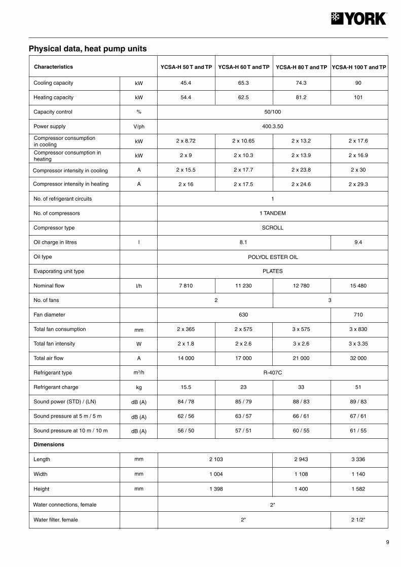
Physical data, heat pump units
YCSA-H 50 T and TP YCSA-H 60 T and TP YCSA-H 80 T and TP YCSA-H 100 T and TPCharacteristics
Cooling capacity 45.4 65.3 74.3 90
Heating capacity 54.4 62.5 81.2 101
Capacity control 50/100
Power supply 400.3.50
2 x 8.72 2 x 10.65 2 x 13.2 2 x 17.6
2 x 9 2 x 10.3 2 x 13.9 2 x 16.9
2 x 15.5 2 x 17.7 2 x 23.8 2 x 30
2 x 16 2 x 17.5 2 x 24.6 2 x 29.3
No. of refrigerant circuits 1
No. of compressors 1 TANDEM
Compressor type SCROLL
Oil charge in litres 8.1 9.4
Oil type
Evaporating unit type PLATES
Nominal flow 7 810 11 230 12 780 15 480
No. of fans 2 3
Fan diameter 630 710
Total fan consumption 2 x 365 2 x 575 3 x 575 3 x 830
Total fan intensity 2 x 1.8 2 x 2.6 3 x 2.6 3 x 3.35
Total air flow 14 000 17 000 21 000 32 000
Refrigerant type R-407C
Refrigerant charge 15.5 23 33 51
Sound power (STD) / (LN) 84 / 78 85 / 79 88 / 83 89 / 83
Sound pressure at 5 m / 5 m 62 / 56 63 / 57 66 / 61 67 / 61
Sound pressure at 10 m / 10 m 56 / 50 57 / 51 60 / 55 61 / 55
Dimensions
Length 2 103 2 943 3 336
Width 1 004 1 108 1 140
Height 1 398 1 400 1 582
2"
Water filter. female 2" 2 1/2"
kW
kW
%
V/ph
kW
kW
A
A
l
l/h
mm
W
A
m3/h
kg
dB (A)
dB (A)
dB (A)
POLYOL ESTER OIL
mm
mm
mm
Compressor consumption in cooling
Compressor consumption in heating
Compressor intensity in cooling
Compressor intensity in heating
Water connections, female

10
No. of pumps 1
Pump consumption 1 350 1 850 2 200 3 120
Pump intensity 2.9 3.4 4.3 5.4
Unit water content 179 181 274 278
Expansion vessel volume 12 18 25
Tank capacity 170 260
Relief valve setting 6
Max. unit power supply consumption 24.3 32.3 38.3 53.9
Max. unit current intensity 46.4 57.7 71 91.5
Start-up current (compressor) 127 167 198 225
Weight (1) 636 720 890 1 065
kPa
kPa
W
A
l
l
l
Bar
kW
A
A
kg
216 230 234 295
208 204 194 294
Available static pressure at rated flow (without filter) (2)
Available static pressure at rated flow (with filter) (3)
Units with Hydro Kit (Version P)
Units without Pack
(1) Weight for unit empty. (2) Available static pressure, Eurovent certified. (3) Pressure with clean filter.
Start-up current (compressor) 127 167 198 225
Cool mode pressure drop 26 48 54 29
Max. unit power supply consumption 22.9 30.4 36.1 50.8
Max. current intensity 43.5 54.3 66.7 86.1
Weight (1) 580 664 824 1 000
A
kPa
kW
A
kg
11
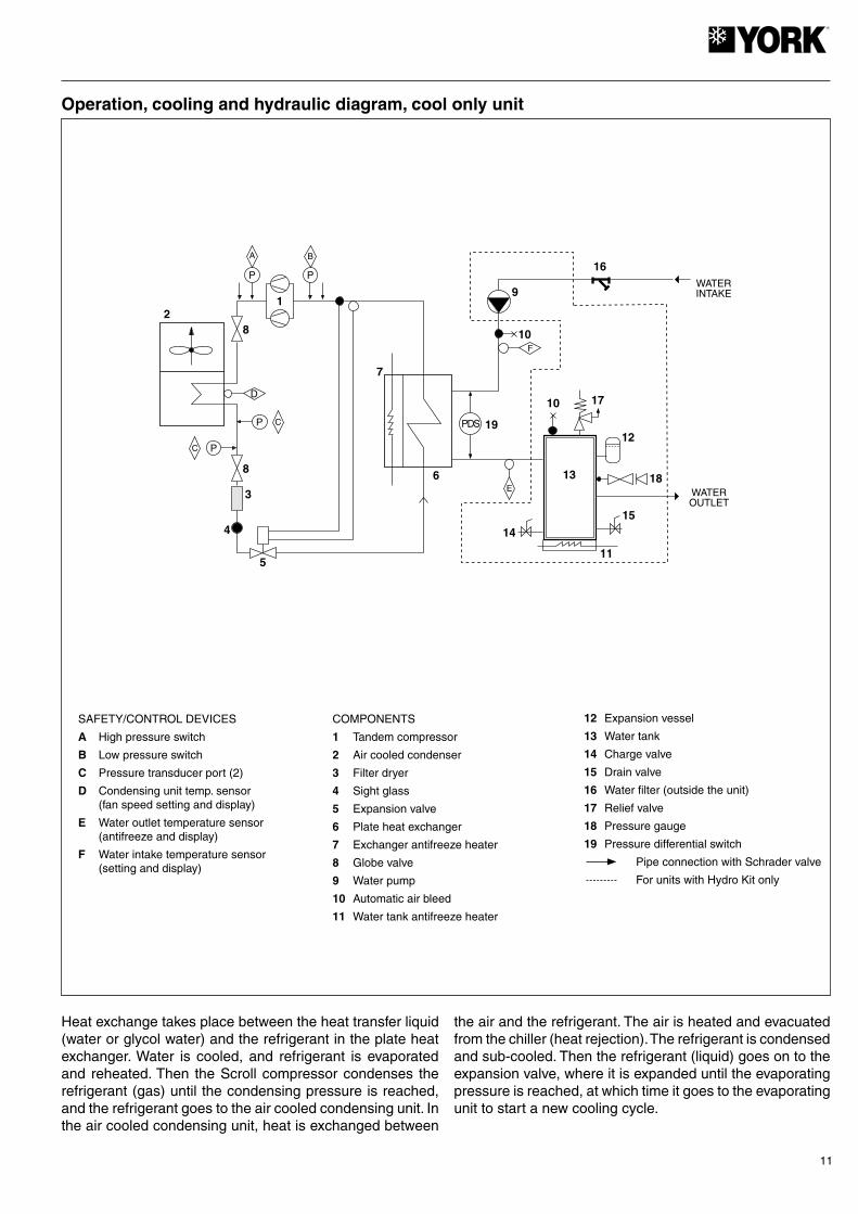
Operation, cooling and hydraulic diagram, cool only unit
SAFETY/CONTROL DEVICES
A High pressure switch
B Low pressure switch
C Pressure transducer port (2)
D Condensing unit temp. sensor (fan speed setting and display)
E Water outlet temperature sensor (antifreeze and display)
F Water intake temperature sensor (setting and display)
COMPONENTS
1 Tandem compressor
2 Air cooled condenser
3 Filter dryer
4 Sight glass
5 Expansion valve
6 Plate heat exchanger
7 Exchanger antifreeze heater
8 Globe valve
9 Water pump
10 Automatic air bleed
11 Water tank antifreeze heater
12 Expansion vessel
13 Water tank
14 Charge valve
15 Drain valve
16 Water filter (outside the unit)
17 Relief valve
18 Pressure gauge
19 Pressure differential switch
Pipe connection with Schrader valve
For units with Hydro Kit only
Heat exchange takes place between the heat transfer liquid (water or glycol water) and the refrigerant in the plate heat exchanger. Water is cooled, and refrigerant is evaporated and reheated. Then the Scroll compressor condenses the refrigerant (gas) until the condensing pressure is reached, and the refrigerant goes to the air cooled condensing unit. In the air cooled condensing unit, heat is exchanged between
the air and the refrigerant. The air is heated and evacuated from the chiller (heat rejection). The refrigerant is condensed and sub-cooled. Then the refrigerant (liquid) goes on to the expansion valve, where it is expanded until the evaporating pressure is reached, at which time it goes to the evaporating unit to start a new cooling cycle.
D
P
A
P
B
1
8
8
PC
5
4
7
9
16
10F
6
PDS 19
E
15
14
11
12
1710
2
3
13 18WATEROUTLET
WATERINTAKE
P C

12
Operation, cooling and hydraulic diagram, heat pump unit
SAFETY/CONTROL DEVICES
A High pressure switch
B Low pressure switch
E Condensing unit temperature sensors (2) (fan speed setting, defrosts and display)
F Water outlet temperature sensor (antifreeze and display)
G Water intake temperature sensor (setting and display)
COMPONENTS
1 Tandem compressor
2 Air cooled condenser
3 Filter dryer
4 Sight glass
5 Expansion valve
6 Plate heat exchanger
7 Exchanger antifreeze heater
8 Globe valve
9 4-way valve
10 Liquid receiver
11 Water pump
12 Automatic air bleed
13 Water tank antifreeze heater
14 Expansion vessel
15 Water tank
16 Charge valve
17 Drain valve
18 Water filter (outside the unit)
19 Relief valve
20 Water pressure gauge
21 Pressure differential switch
22 Check valve
Pipe connection with Schrader valve
For units with Hydro Kit only
Cooling cycleThe 4-way valve is activated. Heat exchange takes place between the heat transfer liquid (water or glycol water) and the refrigerant in the plate heat exchanger. Water is cooled, and refrigerant is evaporated and reheated. Then the Scroll type compressor condenses the refrigerant (gas) until the condensing pressure is reached, and the refrigerant goes to the air cooled condensing unit. In the air cooled condensing unit, heat is exchanged between the air and the refrigerant. The air is heated and evacuated from the chiller (heat rejec-tion). The refrigerant is condensed and sub-cooled. Then the
refrigerant (liquid) goes on to the expansion valve, where it is expanded until the evaporating pressure is reached, at which time it goes to the evaporating unit to start a new cooling cycle.
Heating cycleThe cycle is reversed to heating mode. The 4-way valve is not activated. The condensing unit becomes the evaporating unit, and the evaporating unit becomes the condensing unit. The water in the heat exchanger is heated.
E
3
4
5
7
8
8
2
9ON
P
A B
P
18
1912
11
14
13
21
G
PDS
F
1017
13
16
15 20
6
1
WATEROUTLET
WATERINTAKE
22

13
Outdoor ambient temperature °C DB (80% RH)25 30 32 35 40
Leavingwatertemp.
°C
43 45
Cap. Unit Cap. Unit Cap. Unit Cap. Unit Cap. Unit Cap. Unit Cap. Unit Model
YCSA
50
KW KW KW KW KW KW KW KW KW KW KW KW KW KW
60
80
100
5 52.4 15.3 48.7 16.5 47.7 17.1 46.7 18 42.3 19.2 40.3 20.4 37.4 21.1
6 53.5 15.5 50.7 16.8 49.5 17.3 47.7 18.2 43.7 19.6 41.4 20.7 39.4 21.4
7 55.2 15.7 52.3 17 51 17.5 49.2 18.4 45.1 19.9 42.6 20.9 41.3 21.6
8 56.4 16 53.5 17.3 52.2 17.8 50.3 18.7 46.1 20.3 43.6 21.3 42.6 22
10 58.8 16.6 55.8 18 54.5 18.5 52.5 19.4 48.2 21 45.6 22
12 61.3 17.3 58.1 18.7 56.7 19.3 54.7 20.2 50.2 21.8
15 64.8 18.4 61.4 19.8 60 20.4 57.9 21.3
5 65.2 19.8 60.6 21.3 59.4 22.1 58.1 23.3 52.6 24.9 50.2 26.5 46.5 27.4
6 66.6 20 63 21.7 61.6 22.4 59.3 23.5 54.4 25.3 51.4 26.9 49 27.7
7 68.6 20.2 65 21.9 63.5 22.6 61.2 23.8 56.1 25.8 53 27.1 51.4 28
8 70.1 20.7 66.5 22.4 64.9 23.1 62.6 24.2 57.4 26.3 54.2 27.6 52.9 28.5
10 73.2 21.5 69.4 23.3 67.8 24 65.4 25.2 59.9 27.3 56.7 28.6
12 76.2 22.4 72.2 24.2 70.6 24.9 68.1 26.1 62.4 28.3
15 80.6 23.8 76.4 25.6 74.7 26.4 72.1 27.7
5 83.7 22.7 77.8 24.4 76.2 25.3 74.7 26.7 67.6 28.5 64.5 30.3 59.7 31.3
6 85.5 22.9 81 24.9 79.1 25.7 76.2 26.9 69.9 29 66.1 30.7 62.9 31.7
7 88.1 23.2 83.5 25.1 81.5 25.9 78.6 27.2 72.1 29.5 68.1 31 66 32.1
8 90.1 23.7 85.4 25.7 83.4 26.4 80.4 27.7 73.7 30.1 69.7 31.6 68 32.6
10 94 24.6 89.1 26.6 87.1 27.5 83.9 28.8 77 31.2 72.8 32.7
12 97.9 25.6 92.8 27.7 90.6 28.5 87.4 29.9 80.2 32.4
15 103.6 27.2 98.2 29.3 95.9 30.2 92.6 31.6
5 102.2 32.4 95 34.7 93.1 36 91.2 38 82.6 40.5 78.7 43 73 44.5
6 104.4 32.7 98.9 35.4 96.6 36.6 93.1 38.3 85.3 41.2 80.7 43.7 76.8 45
7 107.6 33.1 102 35.8 99.6 36.9 96 38.7 88 42 83.2 44.1 80.6 45.6
8 110.4 33.7 104.3 36.5 101.8 37.6 98.2 39.4 90 42.8 85.1 44.9 83 46.3
10 114.8 35.1 108.8 37.9 106.3 39.1 102.5 41 94 44.4 88.9 46.5
12 119.6 36.5 113.3 39.4 110.7 40.6 106.8 42.5 97.9 46
15 126.5 38.7 119.9 41.7 117.2 43 113 44.9
Table 1. Cooling capacities YCSA 50-100

14
-5 31.7 12.3 30 13.3 29.3 13.7 28.2 14.4 25.9 15.6 24.5 16.3 23.1 17.2
-4 33.2 12.6 31.4 13.6 30.7 14 29.6 14.7 27.1 16 25.7 16.7 24.1 17.7
-2 36.5 13.1 34.5 14.2 33.7 14.6 32.4 15.3 29.8 16.6 28.1 17.4 26.3 18.4
0 39.9 13.7 37.7 14.8 36.8 15.2 35.5 16 32.5 17.3 30.8 18.2 28.5 19
2 43.5 14.2 41.2 15.4 40.2 15.8 38.7 16.6 35.5 18.1 33.6 18.9 31.7 19.7
4 47.2 14.8 44.6 16 43.6 16.5 42 17.3 38.5 18.8 36.5 19.7 34.4 20.8
-5 39.5 15.8 37.3 17.1 36.4 17.7 35.1 18.5 32.2 20.1 30.5 21.1 28.8 22.3
-4 41.3 16.2 39.1 17.5 38.2 18.1 36.8 18.9 33.7 20.6 31.9 21.6 30 22.8
-2 45.3 16.9 42.9 18.3 41.9 18.9 40.4 19.8 37 21.5 35 22.5 32.7 23.8
0 49.6 17.6 46.9 19 45.8 19.6 44.1 20.6 40.5 22.4 38.3 23.5 35.5 24.7
2 54.2 18.3 51.2 19.8 50.0 20.5 48.2 21.5 44.2 23.4 41.8 24.5 39.5 25.6
4 58.7 19.1 55.5 20.6 54.2 21.3 52.3 22.3 47.9 24.3 45.3 25.5 42.8 26.9
-5 50.7 18.2 47.9 19.7 46.8 20.3 45.1 21.3 41.3 23.1 39.1 24.2 36.9 25.5
-4 53.1 18.6 50.2 20.1 49 20.7 47.2 21.7 43.3 23.6 41 24.7 38.5 26.2
-2 58.2 19.4 55.1 21 53.8 21.6 51.8 22.7 47.6 24.6 45 25.8 42.1 27.2
0 63.7 20.2 60.2 21.9 58.8 22.5 56.6 23.6 52 25.7 49.1 26.9 45.6 28.2
2 69.6 21.1 65.8 22.8 64.2 23.5 61.9 24.6 56.8 26.8 53.7 28.1 50.7 29.2
4 75.4 21.9 71.3 23.7 69.7 24.4 67.1 25.6 61.6 27.8 58.2 29.2 55 30.8
-5 61.9 26 58.5 28.1 57.1 29 55 30.3 50.5 32.9 47.8 34.5 45.1 36.3
-4 64.9 26.6 61.3 28.7 59.9 29.6 57.7 31 52.9 33.6 50.1 35.2 47 37.2
-2 71.1 27.7 67.3 29.9 65.7 30.8 63.3 32.3 58.1 35 54.9 36.7 51.4 38.7
0 77.8 28.8 73.6 31.1 71.8 32.1 69.2 33.6 63.5 36.6 60 38.3 55.7 40.1
2 85 30 80.3 32.4 78.5 33.4 75.6 35 69.4 38.1 65.6 39.9 61.9 41.6
4 92.1 31.2 87.1 33.7 85.1 34.7 82 36.4 75.2 39.6 71.1 41.5 67.2 43.8
Outdoor ambient temperature °C DB (80% RH)
25 30 32 35 40 43 45 ModelYCSA
50
60
80
100
KW KW KW KW KW KW KW KW KW KW KW KW KW KW
Cap. Unit Cap. Unit Cap. Unit Cap. Unit Cap. Unit Cap. Unit Cap. Unit
Leavingwatertemp.
°C
Table 2. Cooling capacities YCSA 50-100 (35% ethylene glycol)
Table 3. Correcting factors for other glycol concentrations
10 1.061 1.025 1.097 1.033
20 1.036 1.015 1.067 1.023
30 1.015 1.005 1.026 1.008
35 1 1 1 1
40 0.985 0.995 0.974 0.992
50 0.954 0.985 0.923 0.977
% in weight
Ethylene glycol Propylene glycol
Capacity Absorbed power Capacity Absorbed power
If it is necessary to make a selection with different glycol percentages, correct the capacity and obsorbed power values in Table 2 (35% ethylene glycol), multiplying them by the coefficients indicated in Table 3.
15
ModelYCSA-H
25 30 32 35 40 43 45
Cap. Unit Cap. Unit Cap. Unit Cap. Unit Cap. Unit Cap. Unit Cap. Unit
50
KW KW KW KW KW KW KW KW KW KW KW KW KW KW
60
80
100
5 48.4 15.5 44.9 16.7 44 17.3 43.1 18.2 39 19.5 37.2 20.7 34.5 21.4
6 49.4 15.7 46.8 17 45.7 17.6 44 18.4 40.4 19.8 38.2 21 36.3 21.6
7 50.9 15.9 48.2 17.2 47.1 17.7 45.4 18.6 41.6 20.2 39.4 21.2 38.1 21.9
8 52 16.2 49.3 17.5 48.2 18.1 46.4 18.9 42.6 20.6 40.2 21.6 39.3 22.3
10 54.3 16.8 51.5 18.2 50.3 18.8 48.5 19.7 44.5 21.3 42 22.3
12 56.6 17.5 53.6 18.9 52.3 19.5 50.5 20.4 46.3 22.1
15 59.8 18.6 56.7 20 55.4 20.6 53.5 21.6
5 69.5 18.7 64.6 20.1 63.3 20.9 62 22 56.2 23.5 53.5 25 49.6 25.9
6 71 18.9 67.3 20.5 65.7 21.2 63.3 22.2 58 23.9 54.9 25.4 52.2 26.2
7 73.2 19.1 69.4 20.7 67.7 21.4 65.3 22.5 59.9 24.4 56.6 25.6 54.9 26.5
8 74.8 19.5 71 21.2 69.3 21.8 66.8 22.9 61.2 24.9 57.9 26.1 56.5 26.9
10 78.1 20.3 74 22 72.3 22.7 69.7 23.8 63.9 25.8 60.5 27
12 81.3 21.1 77.1 22.8 75.3 23.6 72.6 24.7 66.6 26.8
15 86 22.5 81.6 24.2 79.7 25 76.9 26.1
5 79.1 23.4 73.6 25.1 72.1 26 70.6 27.5 63.9 29.3 60.9 31.2 56.5 32.2
6 80.8 23.6 76.5 25.6 74.8 26.4 72 27.7 66 29.8 62.5 31.6 59.4 32.6
7 83.3 23.9 78.9 25.9 77.1 26.7 74.3 28 68.1 30.4 64.4 31.9 62.4 33
8 85.2 24.4 80.7 26.4 78.8 27.2 76 28.5 69.7 31 65.8 32.5 64.3 33.5
10 88.9 25.3 84.2 27.4 82.3 28.3 79.4 29.6 72.8 32.1 68.8 33.7
12 92.6 26.4 87.7 28.5 85.7 29.4 82.6 30.8 75.8 33.3
15 97.9 28 92.8 30.2 90.7 31.1 87.5 32.6
5 95.9 31.5 89.1 33.8 87.3 35.1 85.5 37 77.4 39.5 73.8 41.9 68.4 43.3
6 97.9 31.9 92.7 34.5 90.6 35.6 87.3 37.3 80 40.2 75.7 42.5 72 43.9
7 100.9 32.2 95.6 34.9 93.3 36 90 37.7 82.5 40.9 78 42.9 75.6 44.4
8 103.1 32.9 97.8 35.6 95.5 36.7 92 38.4 84.4 41.7 79.8 43.7 77.9 45.1
10 107.7 34.2 102 36.9 99.7 38.1 96.1 39.9 88.1 43.2 83.3 45.3
12 112.1 35.5 106.2 38.3 103.8 39.6 100.1 41.4 91.8 44.8
15 118.6 37.7 112.4 40.6 109.8 41.8 106 43.8
Outdoor ambient temperature °C DB (80% RH)Leavingwatertemp.
°C
ModelYCSA-H
-5 -3 0 5 7 10 15Cap. Unit Cap. Unit Cap. Unit Cap. Unit Cap. Unit Cap. Unit Cap. Unit
50
KW KW KW KW KW KW KW KW KW KW KW KW KW KW
60
80
100
Outdoor ambient temperature °C DB (80% RH)Leavingwatertemp.
°C
-10
KW KW
Cap. Unit
30 35.5 14.4 33.9 13.2 35.8 13.3 37.7 13.4 41.9 16.2 60.7 17.3 66.6 17.9 77.2 18.9 35 34.0 14.8 33.0 14.1 34.9 14.2 36.7 14.3 40.8 16.9 58.8 17.9 64.5 18.7 75.1 19.8 40 32.2 15.2 32.2 15.3 34.0 15.4 35.7 15.5 39.7 17.6 56.6 18.5 62.4 19.4 72.8 20.8 45 31.3 17.1 33.0 17.2 34.8 17.3 38.6 18.3 54.4 19.3 60.1 20.2 70.4 21.7 50 33.8 19.3 37.5 19.0 52.0 19.9 57.6 20.9 67.9 22.6 30 40.8 16.3 39.0 14.9 41.1 15.0 43.3 15.1 48.1 18.4 69.7 19.6 76.5 20.3 88.7 21.4 35 39.1 16.8 38.0 15.9 40.1 16.0 42.2 16.1 46.9 19.2 67.5 20.3 74.1 21.2 86.3 22.5 40 37.0 17.2 37.0 17.4 39.0 17.5 41.1 17.6 45.6 20.0 65.0 21.0 71.7 22.0 83.7 23.6 45 35.9 19.4 37.9 19.5 39.9 19.6 44.4 20.7 62.5 21.9 69.1 22.9 80.9 24.6 50 38.8 21.9 43.1 21.5 59.7 22.6 66.2 23.8 78.1 25.7 30 53.0 21.8 50.6 19.9 53.5 20.1 56.3 20.2 62.5 24.7 90.5 26.2 99.4 27.2 115.3 28.7 35 50.8 22.5 49.3 21.3 52.1 21.5 54.8 21.6 60.9 25.7 87.7 27.2 96.3 28.4 112.2 30.2 40 48.1 23.0 48.0 23.3 50.7 23.4 53.3 23.6 59.3 26.8 84.5 28.2 93.2 29.6 108.7 31.7 45 46.7 26.1 49.3 26.2 51.9 26.3 57.7 27.8 81.2 29.4 89.8 30.7 105.2 33.1 50 50.4 29.4 56.0 28.9 77.6 30.4 86.0 31.9 101.4 34.6 30 66.0 27.2 63.0 25.0 66.5 25.1 70.0 25.3 77.8 30.7 112.6 32.6 123.6 33.8 143.4 35.6 35 63.2 28.0 61.4 26.6 64.8 26.8 68.2 27.0 75.8 32.0 109.1 33.8 119.8 35.2 139.5 37.5 40 59.8 28.7 59.7 29.0 63.0 29.2 66.4 29.4 73.7 33.3 105.1 35.0 115.9 36.7 135.2 39.3 45 58.1 32.4 61.3 32.6 64.5 32.7 71.7 34.5 101.0 36.5 111.6 38.1 130.8 40.9 50 62.7 36.5 69.7 35.8 96.5 37.7 107.0 39.5 126.2 42.7
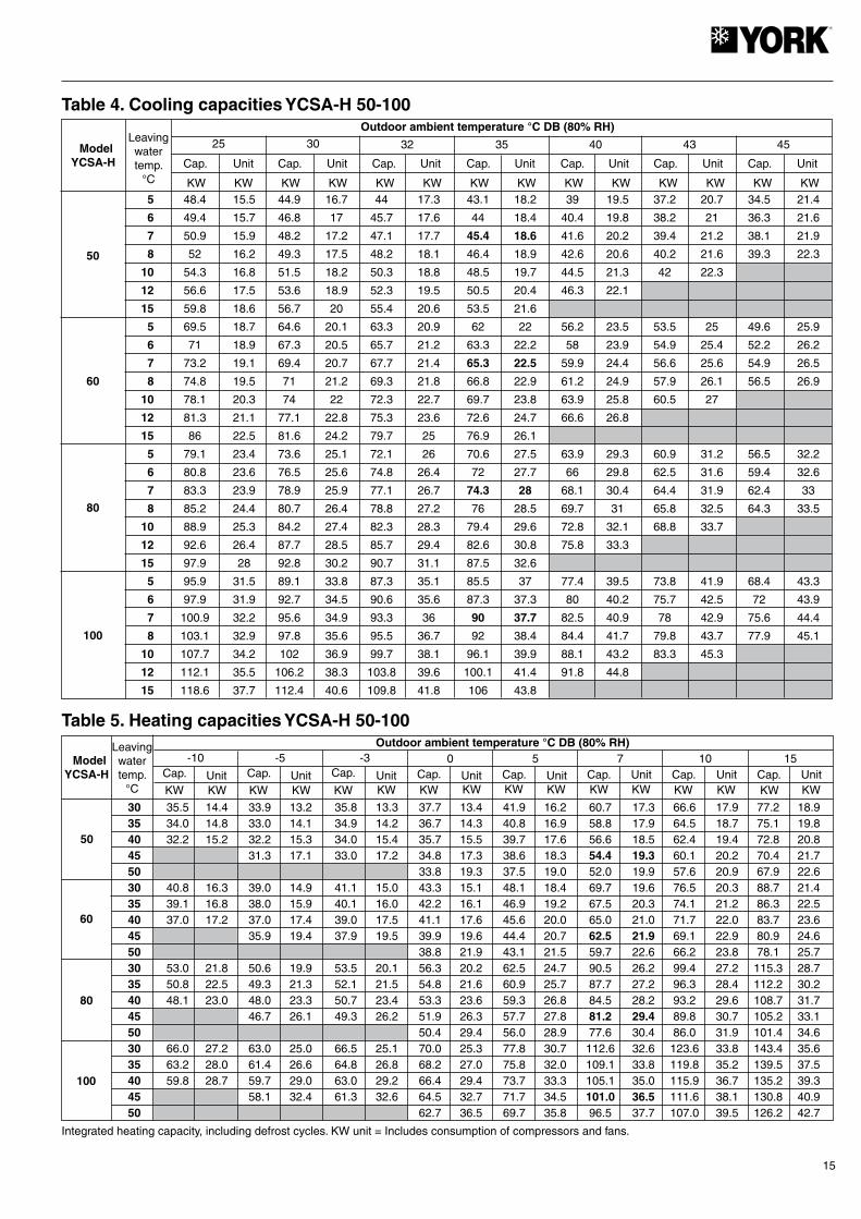
Table 4. Cooling capacities YCSA-H 50-100
Table 5. Heating capacities YCSA-H 50-100
Integrated heating capacity, including defrost cycles. KW unit = Includes consumption of compressors and fans.

16
Table 6. Available pressure for the hydraulic circuit, YCSA/YCSA-H 50-100 with kit(With filter fitted)
Data with water at 10°C. In the case of the use of glycol, apply the correcting factors shown in Tables 2 and 3.
Table 7. Pressure drop in the hydraulic circuit, YCSA/YCSA-H 80-100 without kit(Without filter fitted)
Model Flow l/h Kpa
YCSA/YCSA-H 50 TP
6 000 2616 500 2497 000 2367 500 2238 000 2098 500 1979 000 1839 500 16810 000 15310 500 13811 000 12011 500 10312 000 8412 500 6813 000 47
YCSA/YCSA-H 60 TP
7 500 3598 000 3468 500 3319 000 3159 500 29710 000 27810 500 25911 000 23911 500 21512 000 19112 500 16513 000 13813 500 10614 000 74
YCSA/YCSA-H 80 TP
10 000 27210 500 26511 000 25811 500 25112 000 24512 500 23713 000 22813 500 22014 000 21214 500 20415 000 19215 500 18616 000 17716 500 16717 000 15717 500 14718 000 13818 500 12819 000 11819 500 10620 000 9420 500 8221 000 70
YCSA/YCSA-H 100 TP
12 000 35013 000 33614 000 31915 000 30216 000 28217 000 26018 000 23919 000 21520 000 18821 000 15822 000 12623 000 9124 000 52
Model Flow l/h Kpa
YCSA/YCSA-H 50 T
5 500 126 000 156 500 187 000 217 500 248 000 278 500 309 000 339 500 36.510 000 4010 500 4411 000 4811 500 5212 000 5612 500 6013 000 6413 500 68.514 000 73
YCSA/YCSA-H 60 T
7 500 228 000 258 500 28.59 000 329 500 34.510 000 3710 500 41.511 000 4611 500 49.512 000 5312 500 56.513 000 6013 500 6614 000 7214 500 77.515 000 8315 500 8816 000 9316 500 98.517 000 10417 500 113
YCSA/YCSA-H 80 T
10 000 3711 000 4312 000 4913 000 5514 000 6215 000 6816 000 7417 000 8118 000 8919 000 9720 000 10521 000 11422 000 12422 500 129
YCSA/YCSA-H 100 T
12 000 1913 000 2214 000 2515 000 2816 000 3117 000 3518 000 3919 000 4320 000 4721 000 5222 000 5723 000 6224 000 6725 000 7326 000 7927 000 8527 500 88
17
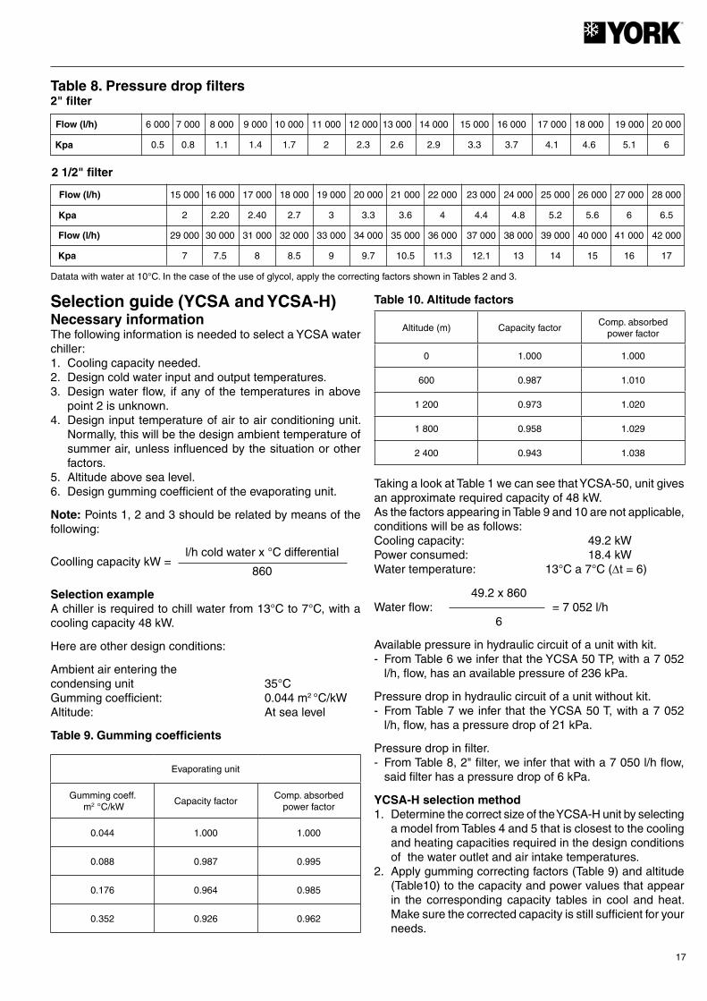
Flow (l/h) 6 000 7 000 8 000 9 000 10 000 11 000 12 000 13 000 14 000 15 000 16 000 17 000 18 000 19 000 20 000
0.5 0.8 1.1 1.4 1.7 2 2.3 2.6 2.9 3.3 3.7 4.1 4.6 5.1 6 Kpa
Table 8. Pressure drop filters2" filter
2 1/2" filter
Flow (l/h) 15 000 16 000 17 000 18 000 19 000 20 000 21 000 22 000 23 000 24 000 25 000 26 000 27 000 28 000
2 2.20 2.40 2.7 3 3.3 3.6 4 4.4 4.8 5.2 5.6 6 6.5
29 000 30 000 31 000 32 000 33 000 34 000 35 000 36 000 37 000 38 000 39 000 40 000 41 000 42 000
7 7.5 8 8.5 9 9.7 10.5 11.3 12.1 13 14 15 16 17
Kpa
Flow (l/h)
Kpa
Datata with water at 10°C. In the case of the use of glycol, apply the correcting factors shown in Tables 2 and 3.
Selection guide (YCSA and YCSA-H)Necessary informationThe following information is needed to select a YCSA water chiller:1. Cooling capacity needed.2. Design cold water input and output temperatures.3. Design water flow, if any of the temperatures in above
point 2 is unknown.4. Design input temperature of air to air conditioning unit.
Normally, this will be the design ambient temperature of summer air, unless influenced by the situation or other factors.
5. Altitude above sea level.6. Design gumming coefficient of the evaporating unit.
Note: Points 1, 2 and 3 should be related by means of the following:
l/h cold water x °C differentialCoolling capacity kW = 860
Selection exampleA chiller is required to chill water from 13°C to 7°C, with a cooling capacity 48 kW.
Here are other design conditions:
Ambient air entering the condensing unit 35°CGumming coefficient: 0.044 m2 °C/kWAltitude: At sea level
Table 9. Gumming coefficients
Table 10. Altitude factors
Taking a look at Table 1 we can see that YCSA-50, unit gives an approximate required capacity of 48 kW.As the factors appearing in Table 9 and 10 are not applicable, conditions will be as follows:Cooling capacity: 49.2 kWPower consumed: 18.4 kWWater temperature: 13°C a 7°C (∆t = 6)
49.2 x 860 Water flow: = 7 052 l/h 6
Available pressure in hydraulic circuit of a unit with kit.- From Table 6 we infer that the YCSA 50 TP, with a 7 052
l/h, flow, has an available pressure of 236 kPa.
Pressure drop in hydraulic circuit of a unit without kit.- From Table 7 we infer that the YCSA 50 T, with a 7 052
l/h, flow, has a pressure drop of 21 kPa.
Pressure drop in filter.- From Table 8, 2" filter, we infer that with a 7 050 l/h flow,
said filter has a pressure drop of 6 kPa.
YCSA-H selection method1. Determine the correct size of the YCSA-H unit by selecting
a model from Tables 4 and 5 that is closest to the cooling and heating capacities required in the design conditions of the water outlet and air intake temperatures.
2. Apply gumming correcting factors (Table 9) and altitude (Table10) to the capacity and power values that appear in the corresponding capacity tables in cool and heat. Make sure the corrected capacity is still sufficient for your needs.
Evaporating unit
Gumming coeff. m2 °C/kW
Capacity factorComp. absorbed
power factor
0.044 1.000 1.000
0.088 0.987 0.995
0.176 0.964 0.985
0.352 0.926 0.962
Altitude (m) Capacity factorComp. absorbed
power factor
0 1.000 1.000
600 0.987 1.010
1 200 0.973 1.020
1 800 0.958 1.029
2 400 0.943 1.038
18
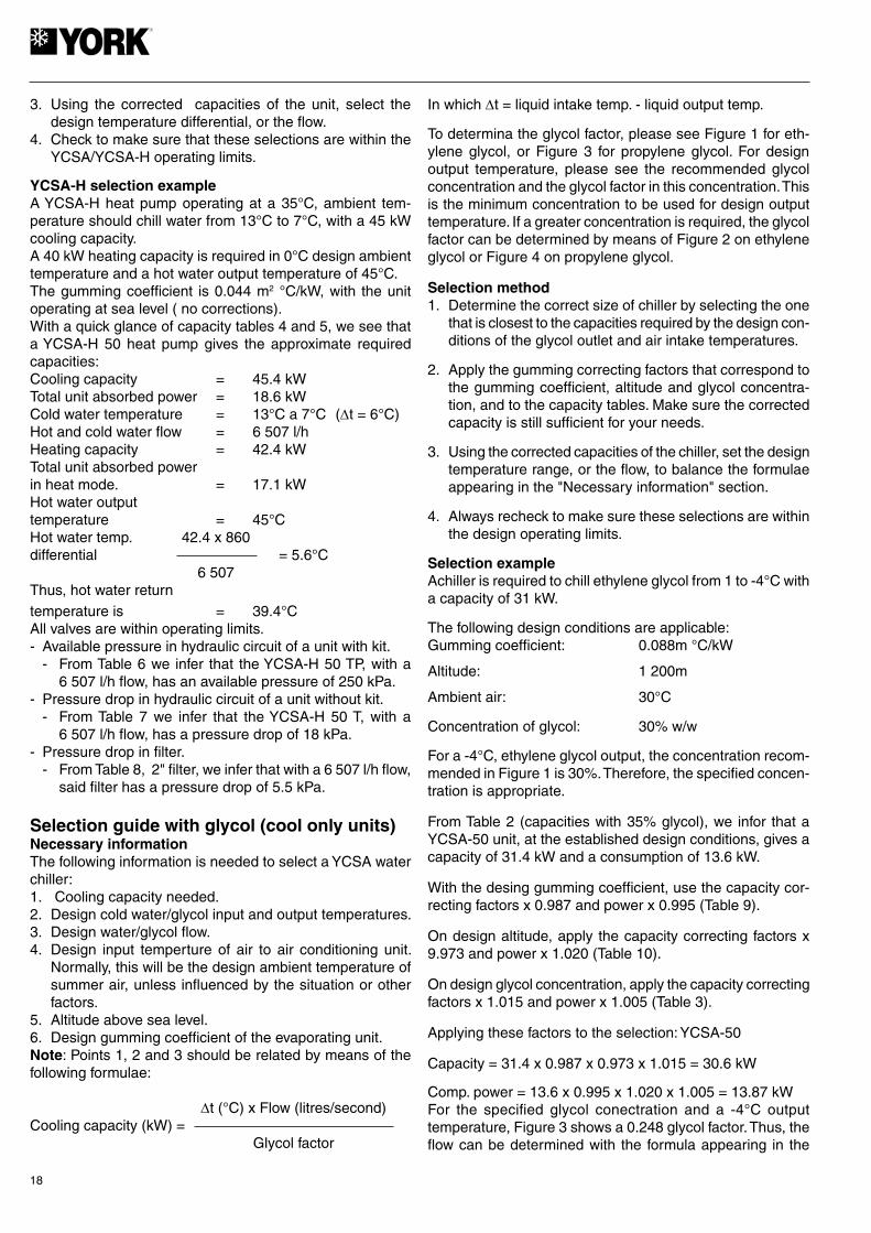
3. Using the corrected capacities of the unit, select the design temperature differential, or the flow.
4. Check to make sure that these selections are within the YCSA/YCSA-H operating limits.
YCSA-H selection exampleA YCSA-H heat pump operating at a 35°C, ambient tem-perature should chill water from 13°C to 7°C, with a 45 kW cooling capacity.A 40 kW heating capacity is required in 0°C design ambient temperature and a hot water output temperature of 45°C.The gumming coefficient is 0.044 m2 °C/kW, with the unit operating at sea level ( no corrections).With a quick glance of capacity tables 4 and 5, we see that a YCSA-H 50 heat pump gives the approximate required capacities:Cooling capacity = 45.4 kWTotal unit absorbed power = 18.6 kWCold water temperature = 13°C a 7°C (∆t = 6°C)Hot and cold water flow = 6 507 l/hHeating capacity = 42.4 kWTotal unit absorbed power in heat mode. = 17.1 kWHot water output temperature = 45°CHot water temp. 42.4 x 860 differential = 5.6°C 6 507Thus, hot water return temperature is = 39.4°CAll valves are within operating limits.- Available pressure in hydraulic circuit of a unit with kit. - From Table 6 we infer that the YCSA-H 50 TP, with a
6 507 l/h flow, has an available pressure of 250 kPa.- Pressure drop in hydraulic circuit of a unit without kit. - From Table 7 we infer that the YCSA-H 50 T, with a
6 507 l/h flow, has a pressure drop of 18 kPa.- Pressure drop in filter. - From Table 8, 2" filter, we infer that with a 6 507 l/h flow,
said filter has a pressure drop of 5.5 kPa.
Selection guide with glycol (cool only units)Necessary informationThe following information is needed to select a YCSA water chiller:1. Cooling capacity needed.2. Design cold water/glycol input and output temperatures.3. Design water/glycol flow.4. Design input temperture of air to air conditioning unit.
Normally, this will be the design ambient temperature of summer air, unless influenced by the situation or other factors.
5. Altitude above sea level.6. Design gumming coefficient of the evaporating unit.Note: Points 1, 2 and 3 should be related by means of the following formulae:
∆t (°C) x Flow (litres/second)Cooling capacity (kW) = Glycol factor
In which ∆t = liquid intake temp. - liquid output temp.
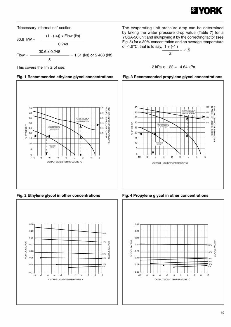
To determina the glycol factor, please see Figure 1 for eth-ylene glycol, or Figure 3 for propylene glycol. For design output temperature, please see the recommended glycol concentration and the glycol factor in this concentration. This is the minimum concentration to be used for design output temperature. If a greater concentration is required, the glycol factor can be determined by means of Figure 2 on ethylene glycol or Figure 4 on propylene glycol.
Selection method1. Determine the correct size of chiller by selecting the one
that is closest to the capacities required by the design con-ditions of the glycol outlet and air intake temperatures.
2. Apply the gumming correcting factors that correspond to the gumming coefficient, altitude and glycol concentra-tion, and to the capacity tables. Make sure the corrected capacity is still sufficient for your needs.
3. Using the corrected capacities of the chiller, set the design temperature range, or the flow, to balance the formulae appearing in the "Necessary information" section.
4. Always recheck to make sure these selections are within the design operating limits.
Selection exampleAchiller is required to chill ethylene glycol from 1 to -4°C with a capacity of 31 kW.
The following design conditions are applicable:Gumming coefficient: 0.088m °C/kW
Altitude: 1 200m
Ambient air: 30°C
Concentration of glycol: 30% w/w
For a -4°C, ethylene glycol output, the concentration recom-mended in Figure 1 is 30%. Therefore, the specified concen-tration is appropriate.
From Table 2 (capacities with 35% glycol), we infor that a YCSA-50 unit, at the established design conditions, gives a capacity of 31.4 kW and a consumption of 13.6 kW.
With the desing gumming coefficient, use the capacity cor-recting factors x 0.987 and power x 0.995 (Table 9).
On design altitude, apply the capacity correcting factors x 9.973 and power x 1.020 (Table 10).
On design glycol concentration, apply the capacity correcting factors x 1.015 and power x 1.005 (Table 3).
Applying these factors to the selection: YCSA-50
Capacity = 31.4 x 0.987 x 0.973 x 1.015 = 30.6 kW
Comp. power = 13.6 x 0.995 x 1.020 x 1.005 = 13.87 kWFor the specified glycol conectration and a -4°C output temperature, Figure 3 shows a 0.248 glycol factor. Thus, the flow can be determined with the formula appearing in the
19
-10 -8 -6 -4 -2 0 2 4 60
5
10
15
20
25
30
35
40
45
0.23
0.24
0.25
0.26
0.27
0.28
OUTPUT LIQUID TEMPERATURE °C
% B
Y W
EIG
HT
GLY
CO
L FA
CTO
R L
/S °
C/K
W IN
RE
CO
MM
EN
DE
D C
ON
CE
NT
RAT
ION
S
GLYCOL FACTOR INRECOMMENDED
CONCENTRATIONS
RECOMMENDEDCONCENTRATION
% BY WEIGHT
FREEZINGPOINT
GLY
CO
L FA
CT
OR
-10 -8 -6 -4 -2 0 2 4 60.23
0%
OUTPUT LIQUID TEMPERATURE °C
0.24
0.25
0.26
0.27
0.28
0.29
0.30
8 10
10%
20%
30%
40%
50%
GLY
CO
L FA
CT
OR
-10 -8 -6 -4 -2 0 2 4 60
5
10
15
20
25
30
35
40
45
0.24
0.25
0.26
OUTPUT LIQUID TEMPERATURE °C
% B
Y W
EIG
HT
GLI
CO
L FA
CTO
R L
/S °
C/K
W IN
RE
CO
MM
EN
DE
D C
ON
EC
TR
ATIO
NS
GLYCOL FACTOR INRECOMMENDED
CONCENTRATIONS
RECOMMENDEDCONCENTRATION
% BY WEIGHT
FREEZINGPOINT
0.23
-10 -8 -6 -4 -2 0 2 4 6
0. 23
0%
OUTPUT LIQUID TEMPERATURE °C
0.24
0.25
0.26
0.27
0.28
0.29
0.30
8 10
10%
20%
30%
40%
50%
GLY
CO
L FA
CT
OR
GLY
CO
L FA
CT
OR
"Necessary information" section.
(1 - (-4)) x Flow (l/s)30.6 kW = 0.248
30.6 x 0.248 Flow = = 1.51 (l/s) or 5 463 (l/h) 5
This covers the limits of use.
The evaporating unit pressure drop can be determined by taking the water pressure drop value (Table 7) for a YCSA-50 unit and multiplying it by the correcting factor (see Fig. 5) for a 30% concentration and an average temperature of -1.5°C, that is to say, 1 + (-4 ) = -1.5 2
12 kPa x 1.22 = 14.64 kPa.
Fig. 1 Recommended ethylene glycol concentrations
Fig. 2 Ethylene glycol in other concentrations
Fig. 3 Recommended propylene glycol concentrations
Fig. 4 Propylene glycol in other concentrations

20
-10 -8 -6 -4 -2 0 2 4 6
LIQUID AVERAGE TEMPERATURE °CC
ON
CE
NT
RAT
ION
OF
GLY
CO
L P
/P
810%
20%
30%
40%
50%
CO
RR
EC
TIN
G F
AC
TO
R
1.50
1.45
1.40
1.35
1.30
1.25
1.20
1.15
1.10
1.05 -10 -8 -6 -4 -2 0 2 4 61.0
LIQUID AVERAGE TEMPERATURE °C
CO
NC
EN
TR
ATIO
N O
F G
LYC
OL
P/P
8
10%
20%
30%
40%
50%
CO
RR
EC
TIN
G F
AC
TO
R
1.1
1.2
1.3
1.4
1.5
1.6
1.7
1.8
125 250 500 1 000 2 000 4 000 8 000 dB(A)
YCSA/YCSA-H 50 76 80 81 76 71 63 58 84
YCSA/YCSA-H 60 77 81 83 78 73 64 59 85
YCSA/YCSA-H 80 78 82 83 81 73 64 59 88
YCSA/YCSA-H 100 79 84 84 82 77 65 60 89
ModelHz
Fig. 5 Ethylene glycol pressure drop correcting factor Fig. 6 Propylene glycol pressure drop correcting factor
Sound power spectrumStandard units
Low noise level units
The data appearing in the tables are sound power values in compliance with the ISO EN 3743 standard.
ModelHz
125 250 500 1 000 2 000 4 000 8 000 dB(A)
YCSA/YCSA-H 50 71 73 74 67 62 53 48 78
YCSA/YCSA-H 60 75 77 78 72 67 56 52 82
YCSA/YCSA-H 80 77 80 80 76 69 56 51 85
YCSA/YCSA-H 100 77 80 81 76 61 58 53 86
21
CAUTION
Installation InstructionsInspectionUpon reception, inspect the merchandise and notify both the carrier and the insurance company, in writing, of any possible damage.
Environmental protectionPackingPacking is made of recyclable material. Its eliminate should be carried out in accordance with the existing local regula-tions on selective collection of residual material.
Elimination of the unitUpon disassembly of the unit, its components should be recuperated ecologically. The cooling circuit contains refrig-erant which should be recovered and returned to the gas manufacturer for recycling. Oil will remain in the sealed compressor and, therefore, it must be returned with its circuit sealed. The air conditioning unit will be deposited in an area estab-lished by the local authorities, for its selective recuperation.
SafetyInstallation and maintenance operations of this air condi-tioning system should be carried out only by qualified and expert personnel. Periodical maintenance operations, such as cleaning the coils and air filters, should be carried out so as to keep unit performance at an optimum.
This unit should be installed and used in accordance with:- Low Voltage Electrotechnical Regulations.- Safety Regulations for Cooling Plants and Installations.- Regulations on Pressure Equipment.- Basic Construction Standards.- Local ordinances
TransportationThe units should always be transported in a vertical position so as to avoid oil leaking out of the compressor. If, for any reason, this position need be changed sporadically, they will remain in that position a strictly necessary period of time.
HandlingThis unit should be handled by using the metal rails supplied for fastening and transportation.
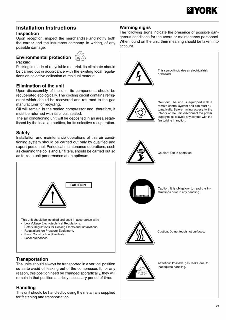
Warning signsThe following signs indicate the presence of possible dan-gerous conditions for the users or maintenance personnel. When found on the unit, their meaning should be taken into account.
This symbol indicates an electrical risk or hazard.
Caution: The unit is equipped with a remote control system and can start au-tomatically. Before having access to the interior of the unit, disconnect the power supply so as to avoid any contact with the fan turbine in motion.
Caution: Fan in operation.
Caution: It is obligatory to read the in-structions prior to any handling.
Caution: Do not touch hot surfaces.
Attention: Possible gas leaks due to inadequate handling.
22
WARNING
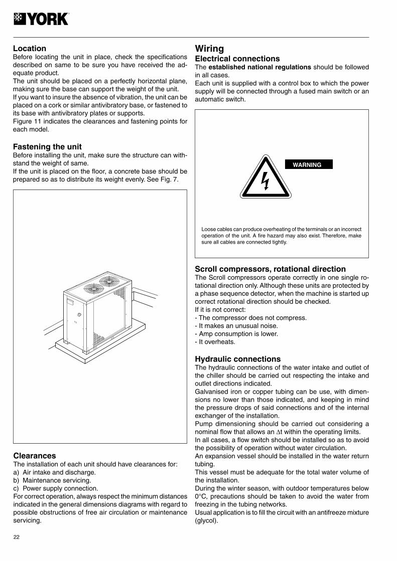
LocationBefore locating the unit in place, check the specifications described on same to be sure you have received the ad-equate product.The unit should be placed on a perfectly horizontal plane, making sure the base can support the weight of the unit.If you want to insure the absence of vibration, the unit can be placed on a cork or similar antivibratory base, or fastened to its base with antivibratory plates or supports.Figure 11 indicates the clearances and fastening points for each model.
Fastening the unitBefore installing the unit, make sure the structure can with-stand the weight of same.If the unit is placed on the floor, a concrete base should be prepared so as to distribute its weight evenly. See Fig. 7.
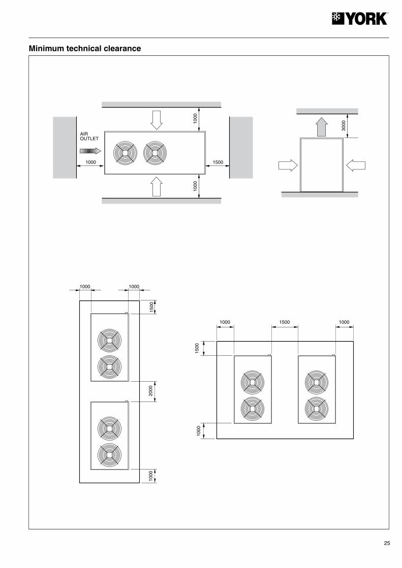
ClearancesThe installation of each unit should have clearances for:a) Air intake and discharge.b) Maintenance servicing.c) Power supply connection.For correct operation, always respect the minimum distances indicated in the general dimensions diagrams with regard to possible obstructions of free air circulation or maintenance servicing.
WiringElectrical connectionsThe established national regulations should be followed in all cases. Each unit is supplied with a control box to which the power supply will be connected through a fused main switch or an automatic switch.
Loose cables can produce overheating of the terminals or an incorrect operation of the unit. A fire hazard may also exist. Therefore, make sure all cables are connected tightly.
Scroll compressors, rotational directionThe Scroll compressors operate correctly in one single ro-tational direction only. Although these units are protected by a phase sequence detector, when the machine is started up correct rotational direction should be checked.If it is not correct:- The compressor does not compress.- It makes an unusual noise.- Amp consumption is lower.- It overheats.
Hydraulic connectionsThe hydraulic connections of the water intake and outlet of the chiller should be carried out respecting the intake and outlet directions indicated.Galvanised iron or copper tubing can be use, with dimen-sions no lower than those indicated, and keeping in mind the pressure drops of said connections and of the internal exchanger of the installation.Pump dimensioning should be carried out considering a nominal flow that allows an ∆t within the operating limits.In all cases, a flow switch should be installed so as to avoid the possibility of operation without water circulation. An expansion vessel should be installed in the water return tubing. This vessel must be adequate for the total water volume of the installation.During the winter season, with outdoor temperatures below 0°C, precautions should be taken to avoid the water from freezing in the tubing networks.Usual application is to fill the circuit with an antifreeze mixture (glycol).

23
YCSA/YCSA-H 50 and 60 T TP
Notes:A- Water intake, Ø 2" Gas F.B- Water outlet, Ø 2" Gas F.C- Auxiliary lines.D- Power supply.E- Water intake 3/8" Gas F.
(4)Ø16,5
347
317
B (2")
A (2")
248
447
59 886
1004
59
1398
E
145
70
C(Ø23)
206 1691
2103
206
D(Ø48)
50 50
AIR OUTLET
Rear view
Side view Front view
AIRINTAKE
View from above
AIRINTAKE
Dimensions and hydraulic connections
24
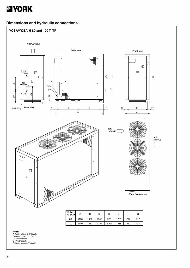
YCSA/YCSA-H 80 and 100 T TP
Notes:A- Water intake, Ø 2" Gas F.B- Water outlet, Ø 2" Gas F.C- Auxiliary lines.D- Power supply.E- Water intake 3/8" Gas F.
(6)Ø16,5
336
G
B (2")
A (2")
389
436
E
145
70
C(Ø23)
F E
C
F
D(Ø61)
50 50
E 67 D
A
67
B
AIR OUTLET
Side view Front view
Rear view
AIRINTAKE
AIRINTAKE
View from above
YCSA/YCSA-H
80
100
A
1108
1140
B
1400
1582
C
2943
3336
D
970
1002
E
1265
1318
F
207
350
G
317
327
Dimensions and hydraulic connections
25
3000
1000 1500
1000
1000
AIROUTLET
1500
2000
1000
10001000
1000 1500 1000
1500
1000
Minimum technical clearance

26
45
12
36
78
9
M6
K3
21
65
43
21
65
43
1413
Q3
K1
21
65
43
M1
21
65
43
K2
21
65
43
M2
21
65
43
L
Q6
(3A
)
N
L1
N
A3T
2
T1
M1
M2
(16)
S2
S1
A4T
2
T1
M1
M2
(29)
S2
S1
FS
L1
L1NN
Q5
Q30
m A
400V
,3 ~
,50H
z,N
,L2
L3
L2L3
IO
L1N
L2L3
(23)
1413 (28) (*)
C1
M3
M4
C2
TK1 (19)
TK2 (31)
M5
C3
TK3 (31)
Y B
K1
(20)
K2
(33)
(70W
)(7
0W)
Q1
Q2
(20)
(33)
A3
(6)
(16)
A4
(7)
(29)
Q4
M5
M4
M3
M1
M2
M7
"B"
mm
Cu
2
0
M6
M7
K4
21
65
43
21
65
43
1413
Q7
(23)
1413 (*)
(22)
2221
2221
Q7
I-24
52d
(1 o
f 3)
YC
SA
/LC
A-
50, 6
0, 8
0, 1
00 (
µC2 )
YC
SA
-H/B
RA
W-
50, 6
0, 8
0, 1
00 (
µC2 )
400.
3.50
YC
SA
/LC
A 5
0/60
YC
SA
-H/B
RA
W 5
0/60
YC
SA
/LC
A 8
0/10
0Y
CS
A-H
/BR
AW
80/
100
MO
TOR
PO
SIT
ION
TH
E C
OM
PO
NE
NT
S IN
CLU
DE
D IN
TH
ES
E B
OX
ES
AR
E S
TAN
DA
RD
AC
CE
SS
OR
IES
TH
E C
OM
PO
NE
NT
S IN
CLU
DE
D IN
TH
ES
E B
OX
ES
AR
E N
OT
SU
PP
LIE
D B
Y T
HE
MA
NU
FAC
TU
RE
R
3x25
+
, N
3x25
+
, N
3x35
+
, N
3x35
+
, N
BA
SE
CO
NT
RO
L M
OD
ULE
EX
PA
NS
ION
MO
DU
LE
TH
ER
MA
L P
RO
TE
CT
OR
CO
MP
RE
SS
OR
1
TH
ER
MA
L P
RO
TE
CT
OR
CO
MP
RE
SS
OR
2
WA
TE
R IN
TAK
E (
NT
C P
RO
BE
)
WA
TE
R O
UT
LET
(N
TC
PR
OB
E)
A1
MO
DU
LE F
AN
SP
EE
D C
ON
TR
OL
CO
OLI
NG
TE
MP
ER
AT
UR
E (
NT
C P
RO
BE
)
A2
MO
DU
LE F
AN
SP
EE
D C
ON
TR
OL
CO
OLI
NG
TE
MP
ER
AT
UR
E (
NT
C P
RO
BE
)
FAN
MO
TO
RS
CO
ND
EN
SE
RS
EV
AP
OR
AT
ING
UN
IT H
EA
TE
R
PR
OT
EC
TIO
N F
US
ES
A1
AN
D A
2(3
15m
A S
LOW
)
SP
EE
D S
WIT
CH
FU
SE
PH
AS
E C
ON
TR
OL
(RO
TAT
ION
AL
DIR
EC
TIO
N O
F C
OM
PR
ES
SO
RS
)
FLO
W S
WIT
CH
FAN
SP
EE
DC
ON
TR
OLL
ER
HIG
H P
RE
SS
UR
E S
WIT
CH
(AU
TO
MA
TIC
RE
SE
T)
LOW
PR
ES
SU
RE
SW
ITC
H(A
UT
OM
AT
IC R
ES
ET
)
CO
MP
RE
SS
OR
1 C
ON
TAC
TO
R
CO
MP
RE
SS
OR
2 C
ON
TAC
TO
R
PU
MP
CO
NTA
CT
OR
CO
MP
RE
SS
OR
S 1
AN
D 2
FAN
S
PU
MP
1
PU
MP
2
DIF
FE
RE
NT
IAL
PR
ES
SU
RE
SW
ITC
HW
AT
ER
CIR
CU
IT
AU
TO
MA
TIC
SW
ITC
HE
S
SU
MP
HE
AT
ER
CO
MP.
1
SU
MP
HE
AT
ER
CO
MP.
2
RE
MO
TE
CO
OL/
HE
AT
RE
MO
TE
ON
/OF
F
230/
24V
TR
AN
SF
OR
ME
R
TAN
K H
EA
TE
R
TH
ER
MA
L P
RO
TE
CT
OR
SFA
NS
M3,
M4
AN
D M
5
4-W
AY
VA
LVE
(YC
SA
-H/B
RA
W O
NLY
)
A1:
A2:
A3:
A4:
B1:
B2:
B3:
B7:
C1,
C2,
C3:
EH
:
F1,
F2:
F3:
FC
:
FS
:
FS
C:
HP
:
LP
:
K1:
K2:
K3:
M1,
M2:
M3,
M4,
M5:
M6:
M7:
PD
W:
Q:
R7:
R8:
RC
H:
RO
O:
T:
TH
:
TK
1, T
K2,
TK
3:
V4V
:
FS
C
LO
AD
R721 22
R821 22
F3
LN
YG
ND
FC
(31)
L1
L3
L2
YC
SA
/LC
AY
CS
A-H
/BR
AW
50 60
Q5
63A
80A
80 100
100A
125A
"B"
mm
2 C
u
Wiring diagram, YCSA/YCSA-H 50, 60, 80 and 100 (µC2), 400.3.50 (1/3)
27
I-24
52d
(2 o
f 3)
YC
SA
/LC
A 5
0, 6
0, 8
0, 1
00 (
µC2 )
YC
SA
-H/B
RA
W 5
0, 6
0, 8
0, 1
00 (
µC2 )
400.
3.50
1314
1011
1215
1619
2021
22
21 3
4 65 21
22
(2)
(8)
BY
N2
N3
N4
2325
26
PLP
RC
HM
1
M2
A3
(6)
PHP
RO
O
TK
1C
5
1718
TK
TK
80 V
A
230V 0V
L1 N
1F1
GO G
B1
GN
D
B2
GN
D
B3 Y
ID5
GN
D
ID3
ID4
ID1
ID2
A1
BB
1B
2B
3
µ ch
iller
2
N1
N2
C½ N3
N4
C¾
C5
N5
C½
C¾
LN
F1
Y B
N1
K1
A1
A2(COMP. 1)
(V4V)
1413
1211
109
8
76
54
32
1
1
7
2
8
3 9
4 10
5 11
6
12
B1
B2
B3
B
J1
J2
F2
F2
T
+TG
ND 2
tLA
N
EH
(75w
)
K3A
1
A2
(PUMP 1)
V4V
(**)
N5
AL
AR
M
a b c d e f g
(*)
(1)
(2)
24V
F1,
F2:
315
mA
(S
low
)
ID4
ID2
ID1
ID3
ID5
TH
(*)
(2x2
00w
)
21 3
4 65 13
14
(0)K
4A1
A2
( ***
)
(0)
(PUMP 2)
21 22
Q3
(1)
(*)
ON
UN
ITS
WIT
H H
YD
RO
KIT
ON
LY A
ND
SIN
GLE
PU
MP
(**)
YC
SA
-H/B
RA
W O
NLY
(***
) O
N U
NIT
S W
ITH
HY
DR
O K
IT O
NLY
AN
D D
UA
L P
UM
P.
WATER INTAKE
WATER OUTLET
PROBE COIL
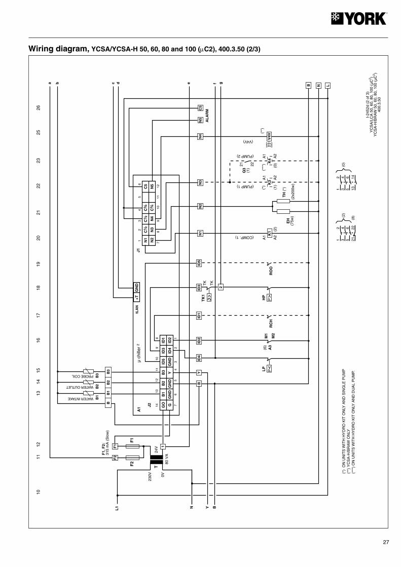
Wiring diagram, YCSA/YCSA-H 50, 60, 80 and 100 (µC2), 400.3.50 (2/3)

28
2728
21 3
4 65 21
22
(3)
(9)
2930
31
M1
M2
B7
+TG
ND
tLA
N/4
85
Y1
TK
3T
K
TK
TK
2T
K
TK
A4
(7)
FS
(1)
Q3
(1)
K3
PD
W
3233
FC
(1)
I-24
52d
(3 o
f 3)
YC
SA
/LC
A 5
0, 6
0, 8
0, 1
00 (
µC2 )
YC
SA
-H/B
RA
W 5
0, 6
0, 8
0, 1
00 (
µC2 )
400.
3.50
PROBE COIL
GO G
B5
GN
D
B6
GN
D
B7
Y1
ID10
GN
D
ID8
ID9
ID6
ID7
A2
µ ch
iller
2 (E
xpan
sión
)
N6
N7
C6/
7
N8
N9
C8/
9C
10
N10
C6/
7
LN
N6
K2A
1
A2
(COMP. 2)
1413
1211
109
8
76
54
32
1
12
34
56
B
J3
J4
78
910
1112
(3)
C8/
9
ID10
ID9
ID7
ID6
ID8 5
4
13 14(*
)
13 14(*
)
3
a b c d e f g y1 LNB
(*)
ON
UN
ITS
WIT
H H
YD
RO
KIT
ON
LY
(***
)14 11
Wiring diagram, YCSA/YCSA-H 50, 60, 80 and 100 (µC2), 400.3.50 (3/3)

29
YCSA/YCSA-H 50, 60, 80 and 100 T/TP
L1
PE
L3
N
L2
POWER SUPPLY400V - 3 + N - ph - 50Hz
N
N3
C
NO
REMOTE ON/OFF SWITCH
PUMP RELAYMÁX 2A RESIST. A 230Vac(VERSION WITHOUT PACK ONLY)
B EXTERNAL GENERALPROTECTION
YCSA CONNECTING STRIP TERMINALS
TERMINALS EXTERNAL EQUIPMENT
YCSA CONNECTING STRIP VOLT-FREE CONTACT
CLIENT WIRING
YCSA CONNECTING STRIPEXTERNAL CONNECTING STRIP
MAIN SWITCH
230 Vca THERMINAL
N5
GENERAL ALARM (VOLT-FREE INVERTERCONTACT, MAX. 2A RESIST. AT 230Vca)
4
B
FLOW SWITCH (ON UNITS WITHOUT A PACK, AND A NOCONTACT FROM THE PUMP CONTACTOR AND A NOCONTACT FROM THE PUMP MEGNETOTHERMALSWITCH IN SERIES WITH THE FLOW SWITCH)
ID5
B
REMOTE HEAT/COOL SWITCH.CLOSED = HEAT, OPEN =COOL(BRAW ONLY)
C5
ID1
ID10
Wiring

30
2 x 15.5 2 x 16 2 x 8.72 2 x 9
2 x 16.5 - 2 x 8.6 -
2 x 17.7 2 x 17.5 2 x 10.65 2 x 10.3
2 x 19.5 - 2 x 11.3 -
2 x 23.8 2 x 24.6 2 x 13.2 2 x 13.9
2 x 23.5 - 2 x 12.8 -
2 x 30 2 x 29.3 2 x 17.6 2 x 16.9
2 x 29.3 - 2 x 17.45 -
Nominal NominalStart
Compressor Fans
Power supply V.ph.Hz.
Model Nominal kWNominal A
AHeatCoolAHeatCool
YCSA-H60
A W
PumpNominal
Nominal
YCSA60
YCSA-H50
YCSA50
127 2 x 3652 x 1.8 2.9
167 2 x 5752 x 2.6 1 8503.4
YCSA-H100
YCSA 100
YCSA-H80
YCSA80
198 3 x 5753 x 2.6 2 2004.3
225 3 x 8303 x 3.35 3 0005.2
400.3.50
- - - -
Voltage limits
Nominal at 400
DB air inlet temperature to coil
Operating cycle
Water outlet temperature
Operating cycle
Temp. differential be-tween the water outlet
and intake
Minimum °C Maximum °C Minimum °C Maximum °C Minimum °C
Maximum °CMinimum Maximum Cool Heat Cool Heat Cool Heat Cool Heat
Model
YCSA 342 436 -10 (3) 46 (2) 6 (1) 15 3 7 -10 20 30 50 (4)
- That the guarantee card has been filled out.
- That maintenance instructions have been given, or a periodical revision contract has been signed.
- That operating instructions have been given to the user.
Check:- That voltage is always between 342 - 436 V.- That the power supply cable section is at
least equal to the section recommended in the corresponding wiring diagrams.
YCSA-H
1 350
W
Electrical characteristics
Limits of use
(1) At lower water temperatures, it is advisable to use glycol type antifreeze mixtures. Minimum Tº with glycol -5 (2) IPESL - SdM - UMT - TÜV, 38°C SAQ, 40°C DUTCH. (3) -18°C with low temperature kit (optional) in models YCSA (4) 50°C if intake air is 0°C.
Prior to final approval of the installation
31
Operating instructions µC2 + Expansion (Rev. 1015)Unit descriptionThis is a multipurpose controller specially programmed for use with air-water chillers and heat pumps equipped with a tandem compressor, two power stages and one single cooling circuit.
Main functions- Water temperature control (at intake or outlet, as per pa-
rameter r6).- Defrost cycle management.- System operating and safety management.- Fan speed control.- Alarm management.- Connection for supervision and telephone assistance (ac-
cess serial connection RS485).
Devices controlled- Compressors- Fans- Four-way valve- Water pump- Alarm device- Heaters
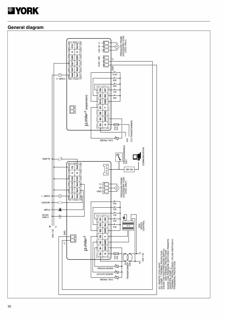
Standard components- System and first compressor control base module. This is the central nucleus that processes the signals coming from the probes and protection elements of the entire system to control its active elements: compressor 1, fans, four-way valve, water circulating pump, alarm relay and antifreeze heater. Power supply 24 Vac.
Can also be used for access and control of the system by means of the display, buttons and LEDs available. Allows selection cool, heat and off functions. Operating parameters can also be modified, and the system can be supervised as well.
- Second compressor expansion and control board. This is an expansion of the base module to be connected by means of two cables. Controls operation of the second compressor.
- Fan speed control module. Operates by phase cut-off. Includes fuse.
- NTC probes. 4 NTC probes are used to read system tem-peratures. One is located at the water intake of the evaporat-ing unit, another at the water outlet of said evaporating unit, and the remaining two at each coil to control the single-phase fan speeds and the defrost cycle.
ParametersThe set of parameters that configure the operating program of the unit is divided into four levels (Factory, Super User, User and Direct), depending upon the function of each parameter and the user’s access level. The parameters of each level can be modified from that same level, as well as lower level parameters.
Factory levelAccessible with the Factory password. Allows configuration of all unit parameters.
Super User levelAccessible with password22. Allows access to the regular parameters the user must adjust.
Direct levelAccessible without a password. Allows reading the values detected by the probes, as well as other system values. Can be used by the user without affecting unit operation.
GeneralModification of the parameters that affect basic unit configura-tion should be made with the controller in Standby position.
32
�ch
iller
² (e
xpan
sion
)
G0 G
B5
GN
D
B6
GN
D
B7 Y
ID10
GN
D
ID8
ID9
ID6
ID7
ID9
ID7
ID6
ID8
ID10
COIL PROBE
315
mA
No
8
C8/
9X X
C10
C6/
7N
o6
No
7
C6/
7
No
9C
8/9
No
10
COMP. 2
tLA
N /
485
GN
DB
8V
+G
0 G
B1
GN
D
B2
GN
D
B3 Y
ID5
GN
D
ID3
ID4
ID1
ID2
ID1:
RE
MO
TE
CO
OL/
HE
ATID
2: C
OM
P. 1
TH
ER
MA
L P
RO
TE
CTO
RID
3/ID
8: F
AN
HIG
H P
RE
SS
UR
E S
WIT
CH
AN
D T
HE
RM
AL
PR
OT
EC
TOR
SID
4/ID
9: L
OW
PR
ES
SU
RE
SW
ITC
HID
5: P
RE
MO
TE
ON
/OF
FID
6: P
OM
P. 2
TH
ER
MA
L P
RO
TE
CTO
RID
7: C
FLO
W S
WIT
CH
D10
:P
RG
EN
ER
AL
PR
OT
EC
TIO
N
ID4
ID2
ID1
ID3
ID5
COIL PROBE
WATER OUTLET
WATER INTAKE
315
mA
24T
RA
NS
FO
RM
ER
230
230.
1.50
NL
VA
NS
PE
ED
CO
NT
RO
L
PR
OG
RA
MM
AB
LEK
EY
CO
MM
UN
ICAT
ION
RS 485
No
3
X X
C5
No
1
No
2
C1/
2
No
4C
3/4
No
5
PUMP
4-WAYVALVE
230.
1.50
ALARM
�ch
iller
²
COMP. 1
N L
C1/
2C
3/4
HEATER
24V
(TO
TR
AN
SF
OR
ME
R)
P
PR
ES
SU
RE
PR
OB
E(A
CC
ES
SO
RY
YC
SA
CO
OL
ON
LY)
GND
B4
V+
+T
GN
D
GN
D+
T
P
PR
ES
SU
RE
PR
OB
E(A
CC
ES
SO
RY
YC
SA
CO
OL
ON
LY)
General diagram

33
Prg+Sel Press 5 secondsProgramming parameters with password
Selects superior parameter within the programming area Simply press or continuous
Increase value Simply press or continuous
Press 5 secondsSelects heat function from standby position and vice-versa (P6=1)
Selects lower parameter within programming area Simply press or continuous
Lower value Simply press or continuous
Selects cool function from standby position and vice-versa (P6=1) Press 5 seconds
Manual alarm reset Press 5 seconds
Clears hour counters (within programming area) Press 5 seconds
Forced manual defrost Press 5 secondsSEL +
+
Sel
Prg/muteLoads values by default Applies voltage when pressed
Return to superior sub-group within programming area until output of same (except changes in E2PROM)
Simply press
Simply pressSelects a Direct parameter and shows its value / Confirms parameter changes
BUTTON UNIT STATUS PRESSING
Press 5 secondsAccess to Direct parameters
µc
²
clear
mutePRG1
2C
AR
EL
PROGRAMHEATINCREMENT/SELECT
COMPRESSOR NUMBERS
SEL
HEAT COOL
COOL CYCLE
ALARM
HEATER(INOPERATIVE)
DEFROST
FAN
PUMP
COMPRESSORS
PARAMETERS/VALUESSELECT
COOLDECREASE/SELECT
Symbols on the displayThe display has three figures in green, plus a symbol and a decimal. It also shows the symbols, in amber, of the functions selected (the alarm symbol is red).
Functions related to the control buttons
Symbol ColourMeaning
With LED on permanently With LED flashing
1;2
Amber
Compressor 1 and/or 2 in operation Timing start-up
Compressors under call -
Water pump in operation -
Fans in operation -
Defrost active -
Red Alarm active -
AmberCool cycle -
Heat cycle -
34
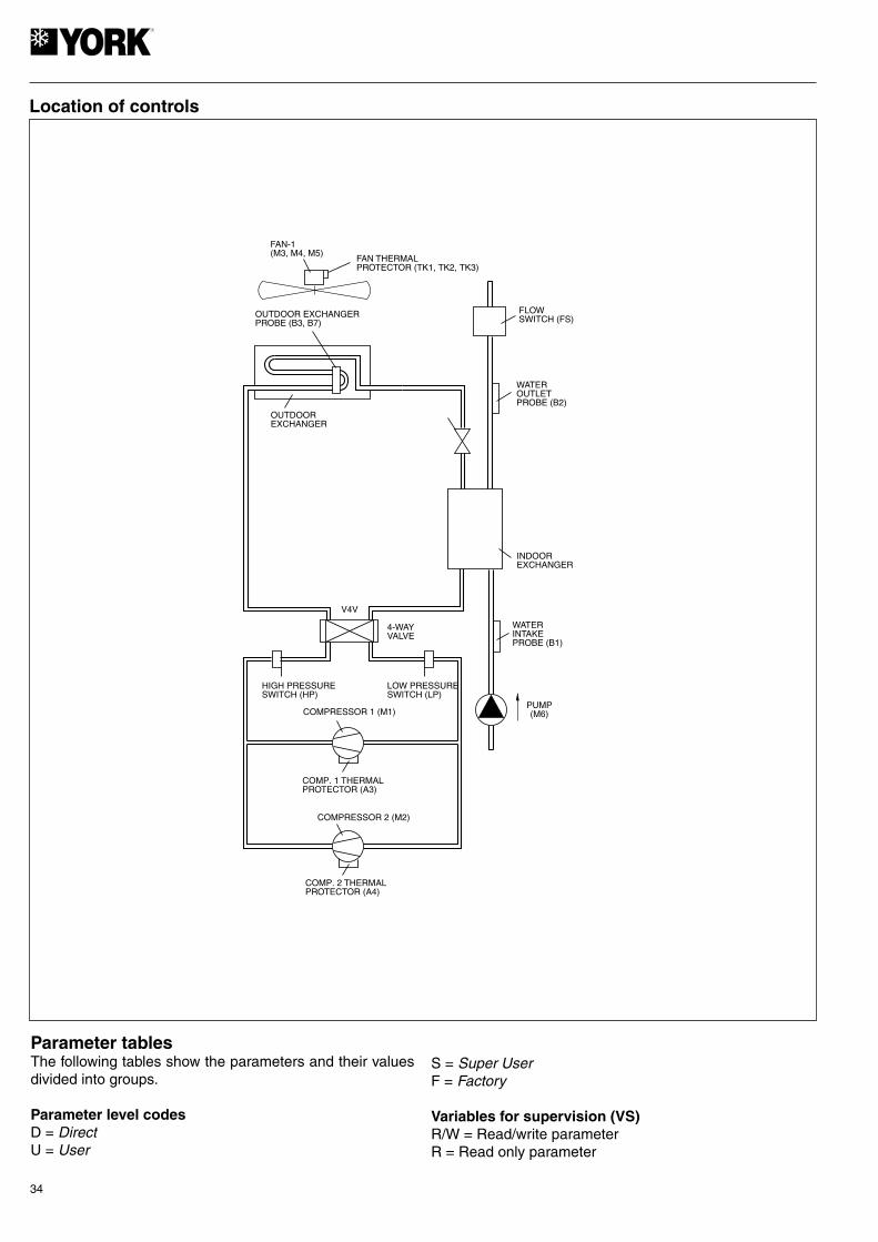
OUTDOOR EXCHANGERPROBE (B3, B7)
FAN-1(M3, M4, M5)
FAN THERMALPROTECTOR (TK1, TK2, TK3)
PUMP(M6)
OUTDOOREXCHANGER
4-WAYVALVE
WATERINTAKEPROBE (B1)
INDOOREXCHANGER
COMP. 1 THERMALPROTECTOR (A3)
HIGH PRESSURESWITCH (HP)
LOW PRESSURESWITCH (LP)
WATEROUTLETPROBE (B2)
FLOWSWITCH (FS)
V4V
COMP. 2 THERMALPROTECTOR (A4)
COMPRESSOR 1 (M1)
COMPRESSOR 2 (M2)
Location of controls
Parameter tablesThe following tables show the parameters and their values divided into groups.
Parameter level codesD = DirectU = User
S = Super UserF = Factory
Variables for supervision (VS)R/W = Read/write parameterR = Read only parameter

35
Display Description Level VS Unit Max Min Value
c01 Minimum operating time U 25 (R/W) Sec. 999 0 120
c02 Minimum OFF time U 26 (R/W) Sec. 999 0 60
c03 Time between start-ups of the same compressor U 27 (R/W) Sec. 999 0 300
c04 Time between start-ups of two compressors U 28 (R/W) Sec. 999 0 3
c05 Time between OFF of two compressors U 29 (R/W) Sec. 999 0 3
c06 Start-up timed U 30 (R/W) Sec. 999 0 10
c07 Compressor start-up delay with regard to the pump U 31 (R/W) Sec. 150 0 20
c08 Pump OFF delay with regard to the compressor U 32 (R/W) Min. 150 0 1
c10 Operating hour counter compressor 1 D 90 (R) Hours 800 0 -
c11 Operating hour counter compressor 2 D 91 (R) Hours 800 0 -
c14 Operating hour counter for compressor maintenance U 34 (R/W) Hours 100 0 0
c15 Operating hour counter for pump D 94 (R/W) Hours 800 0 -
c17 Minimum time between pump start-ups U 35 (R/W) Min. 150 0 5
c18 Minimum operating time for pump U 36 (R/W) Min. 15 0 2
Parameters related to the probes
Display Description Level VS Unit Max. Min. Value
/01 F 1 (R/W) - 1 0 1
/02 F 2 (R/W) - 1 0 1
/03 F 14 (R/W) - 1 0 1
/04(1) F 15 (R/W) - 3 0 0
/07 F 16 (R/W) - 1 0 1
/08(1) F 17(R/W) - 3 0 0
/09(1) Minimum input voltage F 18 (R/W) 0.01 Vdc /10 0 50
/10(1) Maximum input voltage F 19 (R/W) 0.01 Vdc 500 /09 450
/11(1) Minimum pressure F 1 (R/W) bar /12 0 0
/12(1) Maximum pressure F 2 (R/W) bar 99.9 /11 34.5
/13 Calibration probe B1 F 3 (R/W) °C 12 -12 0
/14 Calibration probe B2 F 4 (R/W) °C 12 -12 0
/15 Calibration probe B3 F 5 (R/W) °C 12 -12 0
/16(1) Calibration probe B4 (accessory) F 6 (R/W) bar 12 -12 0
/19 Calibration probe B7 F 9 (R/W) °C 12 -12 0
/20(1) Calibration probe B8 (accessory) F 10 (R/W) bar 12 -12 0
/21 Digital filter U 20 (R/W) - 15 1 4
/22 Input limitation U 21 (R/W) - 15 1 8
/23 Measuring unit 0 = C; 1 = 1F U 5 (R/W) - 1 0 0
b00 Probe viewed on display U 24 (R/W) - 7 0 0
b01 Value read by probe B1 D 70 (R) °C - - -
b02 Value read by probe B2 D 71 (R) °C - - -
b03 Value read by probe B3 D 72 (R) °C - - -
b04(1) Value read by probe B4 D 73 (R) °C/bar - - -
b7 Value read by probe B7 D 76 (R) °C - - -
b08(1) Value read by probe B8 D 77 (R) bar - - -
Parameters related to the probes
NTC B1 probe (water intake); 0=absent (function not avai-lable). 1=present. 1= presente NTC B2 probe (water outlet). 0=absent (function not available). 1=presente NTC B3 probe (refrigerant temp.). 0=absent
Probe type B7 (refrigerant temp.). 0=absent (yes/08=3). 1=present (yes/04=3).
Probe type B4, 0=absent, 1=ON/OFF, 2=NTC, 3=ratiometric 5Vdc.
Probe type B8, 0=absent, 1=ON/OFF, 2=NTC, 3=ratiometric 5Vdc.
(yes/04=3); 1=present (yes/04=0).;
(1) Ratiometric pressure switch probes for low ambient kit applicable on cool only units (accessory for adjusting fan speeds at -18°C). (Change /04=3; /08=3; /03=0; /07=0)

36
ON
C1
SIGNAL
COMPRESSOR
ON
OFF
OFF
t
t
ON
C2
SIGNAL
COMPRESSOR
ON
OFF
OFF
t
t
ON
C3
SIGNAL
COMPRESSOR
ON
OFF
OFF
t
t
C4
SIGNAL 1
SIGNAL 2
COMPRESSOR 2
COMPRESSOR 1
Minimum operating time of a compressor
Minimum OFF time of a compressor
Minimum time between compressor start-ups
Time between start-ups of two compressors

37
C5
SIGNAL 1
COMPRESSOR 1
SIGNAL 2
COMPRESSOR 2
ON
C8
PUMP
COMPRESSOR
ON
OFF
OFF
t
t
PUMP
COMPRESSOR
ON
C7
ON
OFF
OFF
t
t
Time between OFF of two compressors
Compressor/pump OFF delays
Pump/compressor start-up delays
38
FAN SPEED
F9
CONDENSIGTEMPERATUREF8
F10
F4
F3
FAN SPEED
F7
CONDENSINGTEMPERATUREF5
F6
F4
F3
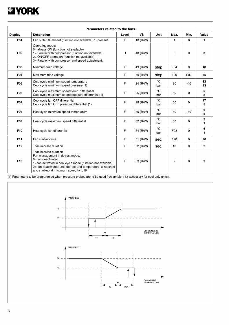
(1) Parameters to be programmed when pressure probes are to be used (low ambient kit accessory for cool only units).
Parameters related to the fans
Display Description Level VS Unit Max. Min. Value
F01 Fan outlet. 0=absent (function not available); 1=present F 10 (R/W) 1 0 1
F02
Operating mode:0= always ON (function not available)1= Parallel with compressor (function not available)2= ON/OFF operation (function not available)3= Parallel with compressor and speed adjustment.
U 48 (R/W) 3 0 3
F03 Minimum triac voltage F 49 (R/W) step F04 0 40
F04 Maximum triac voltage F 50 (R/W) step 100 F03 75
F05Cold cycle minimum speed temperatureCool cycle minimum speed pressure (1)
F 24 (R/W)°Cbar
80 -403213
F06Cool cycle maximum speed temp. differentialCool cycle maximum speed pressure differential (1)
F 26 (R/W)°Cbar
50 053
F07Cool cycle fan OFF differentialCool cycle fan OFF pressure differential (1)
F 28 (R/W)°Cbar
50 0175
F08 Heat cycle minimum speed temperature F 30 (R/W)°Cbar
80 -4065
F09 Heat cycle maximum speed differential F 32 (R/W)°Cbar
50 031
F10 Heat cycle fan differential F 34 (R/W)°Cbar
F08 061
F11 Fan start-up time F 51 (R/W) sec. 120 0 90
F12 Triac impulse duration F 52 (R/W) sec. 10 0 2
F13
Triac impulse durationFan management in defrost mode.0= fan deactivated1= fan activated in cool cycle mode (function not available)2= fan deactivated until defrost end temperature is reached and start-up at maximum speed for d16
F 53 (R/W) 2 0 2

39
Display Description Level VS Unit Max. Min. Value
d01 U 7 (R/W) - 1 0 1
d02 U 8 (R/W) - 1 0 1
d03 Defrost start temperature U 19 (R/W) °C d04 -40 -3
d04 Defrost end temperature U 21 (R/W) °C 80 d03 20
d05 Minimum time for defrost start U 37 (R/W) sec. 150 10 10
d06 Minimum defrost duration U 38 (R/W) sec. 150 0 0
d07 Maximum defrost duration U 39 (R/W) Min. 15 1 9
d08 Time between two defrost cycles U 40 (R/W) Min. 150 10 30
d11 U 9 (R/W) - 0 1 1
d12 Compressor OFF before defrost F 43 (R/W) Min. 3 0 1
d13 Compressor OFF after defrost F 44 (R/W) Min. 3 0 1
d16 F 47 (R/W) sec. 360 0 60
Parameters related to defrost
Execution of defrost 0= no (function not available) 1= yes.
Time or temperature defrost.0= time (function not available).1= temperature
Time of forced vent after defrost (only yes F13=2).
Activation heaters in defrost0= no.1= yes.
DEFROST START
END DEFROST
(d06) MAXIMUMDURATION DEFROSTTIMING START
(d05) MINIMUM TIMEDEFROST START
(d04) DEFROST ENDTEMPERATURE
(d03) DEFROST STARTTEMPERATURE
t
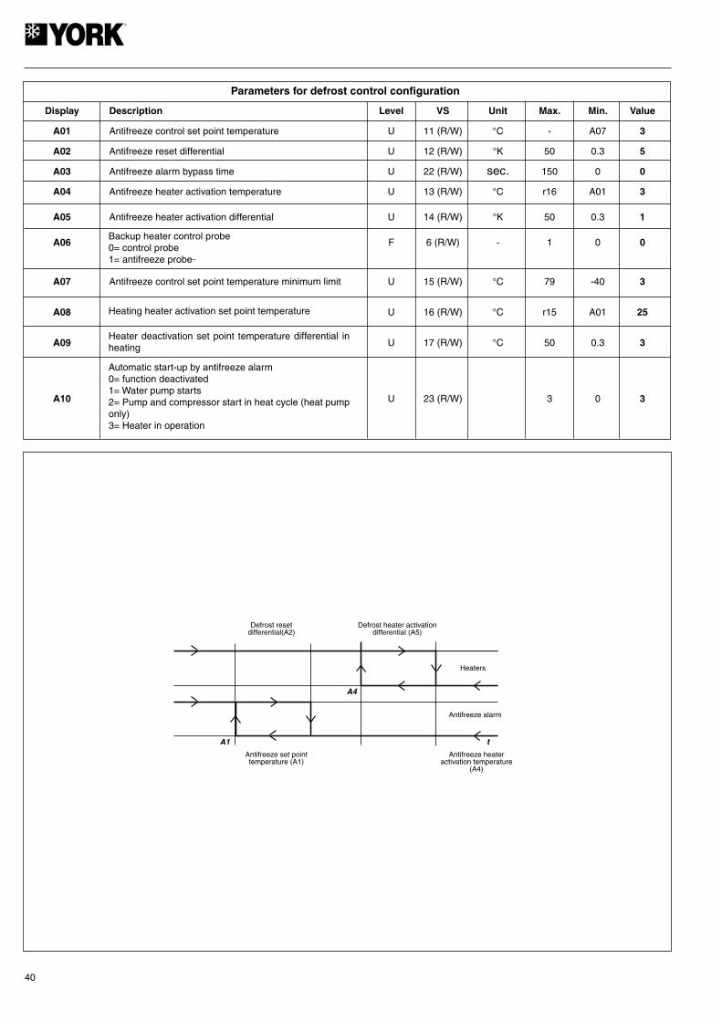
40
Defrost resetdifferential(A2)
A4
Defrost heater activationdifferential (A5)
Heaters
Antifreeze alarm
A1 t
Antifreeze set pointtemperature (A1)
Antifreeze heateractivation temperature
(A4)
Display Description Level VS Unit Max. Min. Value
A01 Antifreeze control set point temperature U 11 (R/W) °C - A07 3
A02 Antifreeze reset differential U 12 (R/W) °K 50 0.3 5
A03 Antifreeze alarm bypass time U 22 (R/W) sec. 150 0 0
A04 Antifreeze heater activation temperature U 13 (R/W) °C r16 A01 3
A05 Antifreeze heater activation differential U 14 (R/W) °K 50 0.3 1
A06 F 6 (R/W) - 1 0 0
A07 Antifreeze control set point temperature minimum limit U 15 (R/W) °C 79 -40 3
A08 U 16 (R/W) °C r15 A01 25
A09 U 17 (R/W) °C 50 0.3 3
A10 U 23 (R/W) 3 0 3
Parameters for defrost control configuration
Automatic start-up by antifreeze alarm0= function deactivated1= Water pump starts2= Pump and compressor start in heat cycle (heat pump only)3= Heater in operation
Backup heater control probe0= control probe1= antifreeze probe
Heater deactivation set point temperature differential in heating
Heating heater activation set point temperature
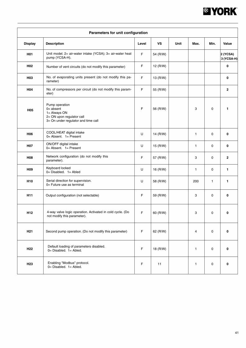
41
Display Description Level VS Unit Max. Min. Value
H01 F 54 (R/W)
H02 F 12 (R/W) 0
H03 F 13 (R/W) 0
H04 F 55 (R/W) 2
F 56 (R/W) 3 0 1
H06 U 14 (R/W) 1 0 0
H07 U 15 (R/W) 1 0 0
H08 F 57 (R/W) 3 0 2
H09 U 16 (R/W) 1 0 1
H10 U 58 (R/W) 200 1 1
H11 Output configuration (not selectable) F 59 (R/W) 3 0 0
H12 F 60 (R/W) 3 0 0
H21 Second pump operation. (Do not modify this parameter) F 62 (R/W) 4 0 0
H22 F 18 (R/W) 1 0 0
H23 F 11 1 0 0
Parameters for unit configuration
Unit model. 2= air-water intake (YCSA); 3= air-water heat pump (YCSA-H).
Pump operation0= absent1= Always ON2= ON upon regulator call3= On under regulator and time call
Number of vent circuits (do not modify this parameter)
No. of evaporating units present (do not modify this pa-rameter)
No. of compressors per circuit (do not modify this param-eter)
COOL/HEAT digital intake0= Absent. 1= Present
ON/OFF digital intake0= Absent. 1= Present
Network configuration (do not modify this parameter).
Keyboard locked0= Disabled. 1= Abled
Serial direction for supervision.0= Future use as terminal
H05
4-way valve logic operation. Activated in cold cycle. (Do not modify this parameter).
Default loading of parameters disabled. 0= Disabled. 1= Abled.
2 (YCSA)3 (YCSA-H)
Enabling "Modbus" protocol. 0= Disabled. 1= Abled.
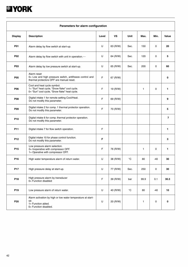
42
Display Description Level VS Unit Max. Min. Value
P01 U 63 (R/W) Sec. 150 0 20
P02 U 64 (R/W) Sec. 120 0 5
P03 U 65 (R/W) Sec. 200 0 60
P05 F 67 (R/W) 0
P06 F 19 (R/W) 1 0 1
P08 F 69 (R/W) 9
P09 F 70 (R/W) 5
P10
P11 Digital intake 7 for flow switch operation. F 1
P12 F 3
P15 F 76 (R/W) 1 0 1
P16 High water temperature alarm of return water. U 38 (R/W) °C 80 -40 30
P17 High pressure delay at start-up. U 77 (R/W) Sec. 250 0 30
P18 F 39 (R/W) bar 99.9 0.1 30.3
P19 Low pressure alarm of return water. U 40 (R/W) °C 80 -40 10
P20 U 20 (R/W) 1 0 0
Parameters for alarm configuration
Alarm delay by flow switch at start-up.
Alarm reset0= Low and high pressure switch, antifreeze control and thermal protectors OFF are manual reset.
Alarm delay by flow switch with unit in operation.
Alarm delay by low pressure switch at start-up.
Cool and heat cycle symbol.1= “Sun” heat cycle, “Snow flake” cool cycle.0= “Sun” cool cycle, “Snow flake” heat cycle.
Digital intake 1 for remote setting Cool/Heat.Do not modify this parameter.
Digital intake 2 for comp. 1 thermal protector operation.Do not modify this parameter.
Low pressure alarm selection.0= Inoperative with compressor OFF.1= Operative with compressor OFF.
Alarm activation by high or low water temperature at start-up.1= Function abled.0= Function disabled.
Digital intake 6 for comp. thermal protector operation.Do not modify this parameter.
High pressure alarm by transducer0= Function disabled
Digital intake 10 for phase control function.Do not modify this parameter.
7
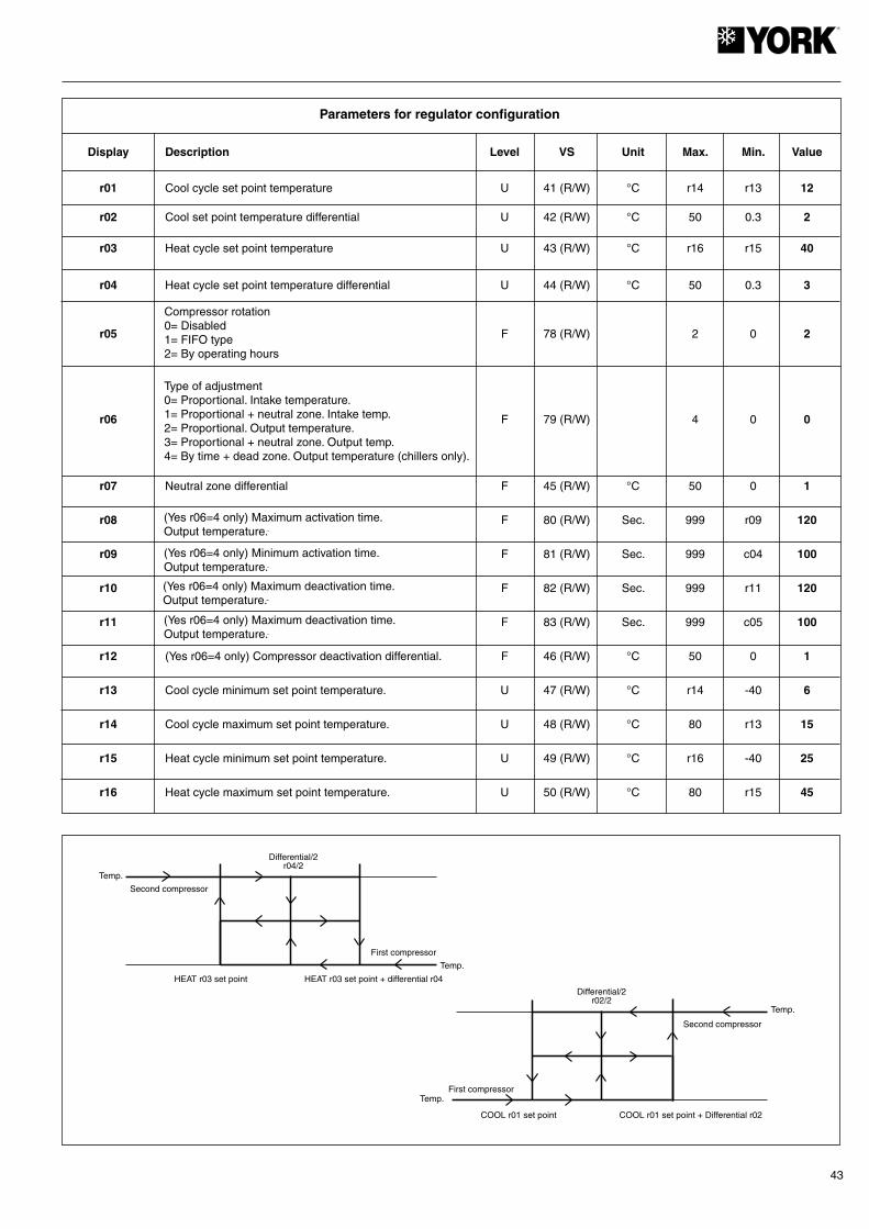
43
Display Description Level VS Unit Max. Min. Value
r01 Cool cycle set point temperature U 41 (R/W) °C r14 r13 12 r02 Cool set point temperature differential U 42 (R/W) °C 50 0.3 2 r03 Heat cycle set point temperature U 43 (R/W) °C r16 r15 40
r04 Heat cycle set point temperature differential U 44 (R/W) °C 50 0.3 3
r05 F 78 (R/W) 2 0 2
r06 F 79 (R/W) 4 0 0
r07 Neutral zone differential F 45 (R/W) °C 50 0 1
r08 F 80 (R/W) Sec. 999 r09 120
r09 F 81 (R/W) Sec. 999 c04 100
r10 F 82 (R/W) Sec. 999 r11 120
r11 F 83 (R/W) Sec. 999 c05 100
r12 (Yes r06=4 only) Compressor deactivation differential. F 46 (R/W) °C 50 0 1
r13 Cool cycle minimum set point temperature. U 47 (R/W) °C r14 -40 6
r14 Cool cycle maximum set point temperature. U 48 (R/W) °C 80 r13 15
r15 Heat cycle minimum set point temperature. U 49 (R/W) °C r16 -40 25
r16 Heat cycle maximum set point temperature. U 50 (R/W) °C 80 r15 45
Parameters for regulator configuration
Compressor rotation0= Disabled1= FIFO type2= By operating hours
Type of adjustment0= Proportional. Intake temperature.1= Proportional + neutral zone. Intake temp.2= Proportional. Output temperature.3= Proportional + neutral zone. Output temp.4= By time + dead zone. Output temperature (chillers only).
(Yes r06=4 only) Maximum activation time.Output temperature.
(Yes r06=4 only) Minimum activation time.Output temperature.
(Yes r06=4 only) Maximum deactivation time.Output temperature.
(Yes r06=4 only) Maximum deactivation time.Output temperature.
Differential/2r04/2
Second compressor
HEAT r03 set point HEAT r03 set point + differential r04
First compressor
Temp.
Temp.
Temp.
Differential/2r02/2
Second compressor
COOL r01 set point COOL r01 set point + Differential r02
First compressor
Temp.

44
Reset of alarmsPressing the UP and DOWN keys for 5 seconds cancels alarms present in the memory. At the same time, the alarm message disappears from the display and the alarm relay is deactivated.
Forced defrost (heat pumps)Pressing the SEL and UP keys simultaneously for 5 seconds activates forced defrost of the unit.
Clearing hour countersWhile reading compressor or pump (c10, c11 and c15) op-erating hours, said counters can be cleared by pressing the UP and DOWN keys simultaneously.
Pump operation4 operating modes can be selected in accordance with the value given to parameter H5. H5=0 (pump disabled). H5=1 (pump always on), H5=2 (pump on controlled by the regula-tor or in parallel with the compressor), H5=3 (pump starts and stops at regular intervals, independent of compressor
operation) (parameters c17 and c18).
Calibration of probesIf necessary, probes can be calibrated by using parameters /13, /14, /15, /16, /19 and /20. See Parameters related to probes table.
Remote ON/OFFA remote ON/OFF intake can be connected between termi-nals D5 and B of the connecting strip. To activate said intake, a value of 1 should be given to parameter H07 (H07= 1). With this intake open the unit is OFF; when closed, the unit is ON. This function does not disable the ON/OFF function of the keyboard.
Remote COOL/HEATA remote COOL/HEAT intake can be connected between terminals D1 and B of the connecting strip. To activate said intake, a value of 1 should be given to parameter H06 (H06= 1). With this intake open the unit is in HEAT; when closed, the unit is in COOL. This function does not disable the COOL/HEAT function of the keyboard.
Table of alarms
Display Alarm type Reset
A1 Antifreeze alarm Manual
AHt High temp. at start-up (if activated, P20=1) Automatic
ALt Low temp. at start-up (if activated, P20=1) Automatic
d1-2 Defrost in operation -
dF1-2 Problem in defrost Automatic
E1 Probe B1 Automatic
E2 Probe B2 Automatic
E3 Probe B3 Automatic
E4 Probe B4 Automatic
E7 Probe B7 Automatic
E8 Probe B8 Automatic
ELS Low supply voltage Automatic
EHS High supply voltage Automatic
EPr Eprom error. Unit in operation. Automatic
EPb Eprom error. At start-up Automatic
ESP Communication failure with the expansion module Automatic
EL 1-2 Problem at fan voltage control Automatic
FL Flow switch Manual
Hc1/Hc2 Compressor maintenance alarm Automatic
HP1/HP2 High pressure Manual
HP1 Fan 1 thermal protection (TK1) Manual
HP2 Fan 2 and 3 thermal protection (TK2 and TK3) Manual
HT High water temperature warning Automatic
LP1/LP2 Low pressure Manual
tC1 Compressor 1 thermal switch Manual
tC2 Compressor 2 thermal switch Manual
TP Phase order failure/Phase failure Manual
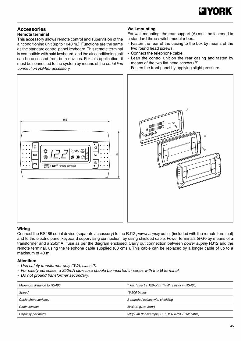
45
15682Set
1234
µc ²CAREL
Set
Prg
Sel
remote terminal
A
B
AccessoriesRemote terminalThis accessory allows remote control and supervision of the air conditioning unit (up to 1040 m.). Functions are the same as the standard control panel keyboard. This remote terminal is compatible with said keyboard, and the air conditioning unit can be accessed from both devices. For this application, it must be connected to the system by means of the serial line connection RS485 accessory.
Wall-mountingFor wall-mounting, the rear support (A) must be fastened to a standard three-switch modular box.- Fasten the rear of the casing to the box by means of the
two round head screws.- Connect the telephone cable.- Lean the control unit on the rear casing and fasten by
means of the two flat head screws (B).- Fasten the front panel by applying slight pressure.
WiringConnect the RS485 serial device (separate accessory) to the RJ12 power supply outlet (included with the remote terminal) and to the electric panel keyboard supervising connection, by using shielded cable. Power terminals G-G0 by means of a transformer and a 250mAT fuse as per the diagram enclosed. Carry out connection between power supply RJ12 and the remote terminal, using the telephone cable supplied (80 cms.). This cable can be replaced by a longer cable of up to a maximum of 40 m.
Attention:- Use safety transformer only (3VA, class 2).- For safety purposes, a 250mA slow fuse should be inserted in series with the G terminal.- Do not ground transformer secondary.
Maximum distance to RS485 1 km. (insert a 120-ohm 1/4W resistor in RS485)
Speed 19.200 bauds
Cable characteristics 2 stranded cables with shielding
Cable section AWG22 (0.35 mm²)
Capacity per metre >90pF/m (for example, BELDEN 8761-8762 cable)
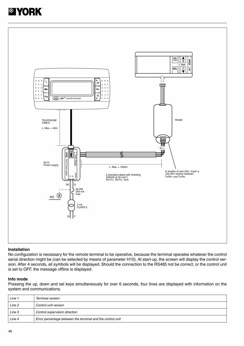
46
Set
µc ²CAREL
Set
Prg
Sel
mute
Car
el
clear
SEL
PRG
CA
RE
L
µc
²
In lengths of over 20m. Insert a120-ohm resistor betweenTx/Rx+ and Tx/Rx-
L. Max. = 40m
RJ12Power supply
remote terminal
RJ12 P
ower supply
GN
DR
S485
24Vac
G8
N F
3 VACLASS 2
L. Max. = 1000m
G0 G
SLOW250 mAfuse
RS485TELEPHONECABLE
G + -
NO
2 stranded cables with shieldingAWG22 (0.35 mm )Rx/Tx+, Rx/Tx-, Gnd
2
InstallationNo configuration is necessary for the remote terminal to be operative, because the terminal operates whatever the control serial direction might be (can be selected by means of parameter H10). At start-up, the screen will display the control ver-sion. After 4 seconds, all symbols will be displayed. Should the connection to the RS485 not be correct, or the control unit is set to OFF, the message offline is displayed.
Info modePressing the up, down and sel keys simultaneously for over 6 seconds, four lines are displayed with information on the system and communications.
Line 1 Terminal version
Line 2 Control unit version
Line 3 Control supervision direction
Line 4 Error percentage between the terminal and the control unit
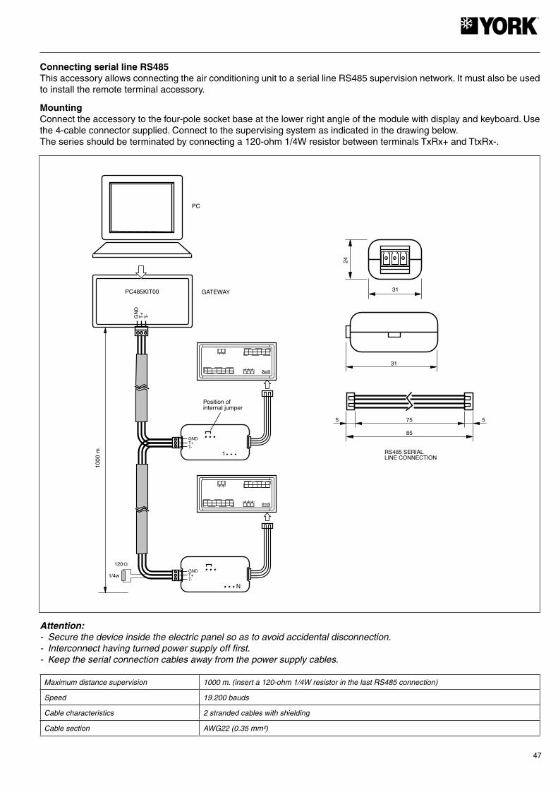
47
31
RS485 SERIALLINE CONNECTION
55 75
85
31
24
1/4w
1000
m
PC485KIT00
120 �
GNDT+T-
1
N
Position ofinternal jumper
GNDT+T-
GN
DT
+T-
GATEWAY
PC
Connecting serial line RS485This accessory allows connecting the air conditioning unit to a serial line RS485 supervision network. It must also be used to install the remote terminal accessory.
MountingConnect the accessory to the four-pole socket base at the lower right angle of the module with display and keyboard. Use the 4-cable connector supplied. Connect to the supervising system as indicated in the drawing below.The series should be terminated by connecting a 120-ohm 1/4W resistor between terminals TxRx+ and TtxRx-.
Attention:- Secure the device inside the electric panel so as to avoid accidental disconnection.- Interconnect having turned power supply off first.- Keep the serial connection cables away from the power supply cables.
Maximum distance supervision 1000 m. (insert a 120-ohm 1/4W resistor in the last RS485 connection)
Speed 19.200 bauds
Cable characteristics 2 stranded cables with shielding
Cable section AWG22 (0.35 mm²)

48
RATIOMETRICTRANSDUCERS
PACKARDCONNECTORS
EXPANSION BOARD
TERMINAL
GND B4 V+
Gre
en
Whi
te
Bla
ck
GND B4 V+
Gre
en
Whi
te
Bla
ck
LIQUID LINE
SCHRADERCONNECTORS
GO
G
B1
GND
B2
GND
B3
Y
ID5
GND
ID3
ID4
ID1
ID2
µ chiller 2
GO
G
B1
GND
B2
GND
B3
Y
ID5
GND
ID3
ID4
ID1
ID2
No1
No2
C½No3 No4
C¾ C5
No5
C½C¾
x
x
No1
No2
C½No3 No4
C¾ C5
No5
C½C¾
x
x
Low ambient temperature kit (ratiometric transducers)Applicable only to cool only units to adjust the condensing pressure at a low ambient temperature (to -18º C).Includes:2 ratiometric pressure transducers.2 Packard connectors.2 three-way connectors.
Attention: Install the kit with power supply to the unit turned off.
Mounting pressure transducers on the cooling circuitScrew the two ratiometric transducers on to the two free Schrader valves located in the liquid line of the unit. Check for leaks.
Mounting the Packard connectorsConnect the three Packard connector cables to the two three-way connectors and at the two regulator modules as indicated below.

49
Red LED flashing Batteries low at starting to copy Replace batteries
Green LED flashing Batteries low at end of copy Replace batteries
Red/green LEDs flashing (orange signal) This can happen only when downloading the program. Check program on the key.
Red and green LEDs on
Red LED always on
LEDs off Batteries disconnected Check batteries.
Transmission error
Copy error
Instrument not compatible
LED SIGNAL ERROR MEANING & SOLUTION
Repeat operation. If this error persists, check bat-teries and key connection.Repeat operation. If this error persists, check bat-teries and key connection.
LEDS PROGRAMMABLE KEY
CHARGE BUTTON
CONNECTOR
BATTERIES
ACCESS COVER
DIP-SWITCH
Disconnection of probes B3 and B7Disconnect the terminals of probes B3 and B7 from the connecting strip to cancel them.
Modifying parameters- Power the system.- Select standby on the regulator.- Enter the parameter programming system by means of the password.- Modify the following parameters in accordance with the values indicated: /03= 0; /04= 3; /07= 0; /08=3; F05= 13; F06= 3;
F07= 5; P18= 30.3. Start the unit and check operation.
Programmable keyAllows up and downloading the operating program of the unit.This can be carried out with the power supply to the unit off, as they key has internal batteries (3 1.5V 190mA Duracell D357H or equivalent batteries).
Downloading unit program to the key- Remove the key cover and set the two dip switches to OFF. Replace the cover.- Insert the end of the key (four-pole socket connector) on to the pin connector at the bottom right of the module with display
and keyboard.- Press the key button. The LED goes on in red. Once download is over, this LED turns green. Once this sequence is over,
you can release the button and disconnect the key from the module.
Uploading program from the key to the unit- Remove the key cover and set the two dip switches: dip switch 1 to OFF, dip switch 2 to ON. Replace the cover.- Insert the end of the key (four-pole socket connector) on to the pin connector at the bottom right of the module with display
and keyboard.- Press the key button. The LED goes on in red. Once upload is over, this LED turns green. Once this sequence is over,
you can release the button and disconnect the key from the module.
Messages of the LEDs
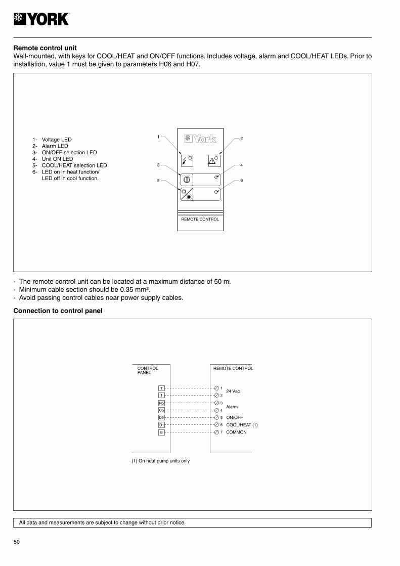
50
!
1 2
4
6
3
5
REMOTE CONTROL
T
D5
N5
C5
124 Vac
REMOTE CONTROLCONTROLPANEL
1
2
3
4
D1
B
5
6
7
Alarm
ON/OFF
COOL/HEAT (1)
COMMON
(1) On heat pump units only
Remote control unitWall-mounted, with keys for COOL/HEAT and ON/OFF functions. Includes voltage, alarm and COOL/HEAT LEDs. Prior to installation, value 1 must be given to parameters H06 and H07.
1- Voltage LED2- Alarm LED3- ON/OFF selection LED4- Unit ON LED5- COOL/HEAT selection LED6- LED on in heat function/ LED off in cool function.
- The remote control unit can be located at a maximum distance of 50 m.- Minimum cable section should be 0.35 mm².- Avoid passing control cables near power supply cables.
Connection to control panel
All data and measurements are subject to change without prior notice.


www.johnsoncontrols.com