Embed Size (px)
DESCRIPTION
Air Admittance Valves
Citation preview
T: 1300 815 127 www.pic.vic.gov.au
PO Box 536 Melbourne Victoria, Australia 3001
Goods Shed North 733 Bourke Street Docklands, Victoria 3008
1: SANITARY PLUMBING TECHNICAL SOLUTION 1.01
AIR ADMITTANCE VALVES
Page 1
AIMThe aim of this technical solution is to clarify the requirements for ventilation of sanitary plumbing and drainage systems where air admittance valves are installed.
PLUMBING REGULATIONS 2008The Plumbing Code of Australia (PCA) is adopted by and forms part of the Plumbing Regulations 2008. Part C1 of the PCA specifies the objectives and performance requirements related to the installation of sanitary plumbing systems. AS/NZS 3500.2: Plumbing and drainage Part 2: Sanitary plumbing and drainage is a “deemed to satisfy” document listed in Part C1 of the PCA and contains a section on “General design requirements for sanitary plumbing systems”.
BACKGROUNDAir Admittance Valves (AAV’s) may be installed as an alternative to a piped vent, providing that certain conditions are observed. AAV’s must comply with the product standard AS/NZS 4936: Air admittance valves (AAV’s) for use in sanitary plumbing and drainage systems. AAV’s are available as a single unit or may be formed as an integral part of a fixture trap. In Australia, AAV’s having the “W” (WaterMark) approval may be used in sanitary plumbing systems.Except for fixtures discharging to gullies, AAV’s may be used to vent fixture discharge pipes where the fixture discharge pipe exceeds the maximum permitted length. AAV’s may be used in sanitary plumbing systems for trap vents, group vents, branch vents and stack vents, and for the ventilation of branch drains.
1. USING AAV’S INSTEAD OF PIPED VENTSAS/NZS 3500.2 permits AAV’s to be used as (see figures 3 to 8):
> An option to a Trap Vent in any system of plumbing where a single fixture discharge pipe exceeds the maximum permitted distance.
> An option to a Group Vent or Branch Vent in the Fully Ventilated (Modified) System of Plumbing.
> An option to a Stack Vent, where the stack extends through less than 10 floor levels.
> An option for the ventilation of a Branch Drain where the combined length of the drain and fixture discharge pipe exceeds ten metres.
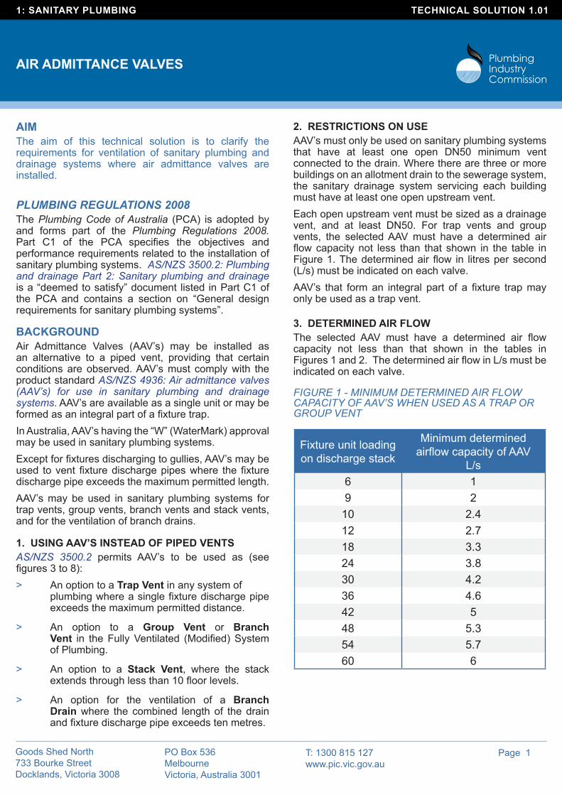
2. RESTRICTIONS ON USEAAV’s must only be used on sanitary plumbing systems that have at least one open DN50 minimum vent connected to the drain. Where there are three or more buildings on an allotment drain to the sewerage system, the sanitary drainage system servicing each building must have at least one open upstream vent. Each open upstream vent must be sized as a drainage vent, and at least DN50. For trap vents and group vents, the selected AAV must have a determined air flow capacity not less than that shown in the table in Figure 1. The determined air flow in litres per second (L/s) must be indicated on each valve.AAV’s that form an integral part of a fixture trap may only be used as a trap vent.
3. DETERMINED AIR FLOW The selected AAV must have a determined air flow capacity not less than that shown in the tables in Figures 1 and 2. The determined air flow in L/s must be indicated on each valve.
FIGURE 1 - MINIMUM DETERMINED AIR FLOW CAPACITY OF AAV’S WHEN USED AS A TRAP OR GROUP VENT
Fixture unit loading on discharge stack
Minimum determined airflow capacity of AAV
L/s6 19 2
10 2.412 2.718 3.324 3.830 4.236 4.642 548 5.354 5.760 6
T: 1300 815 127 www.pic.vic.gov.au
PO Box 536 Melbourne Victoria, Australia 3001
Goods Shed North 733 Bourke Street Docklands, Victoria 3008
1: SANITARY PLUMBING TECHNICAL SOLUTION 1.01
AIR ADMITTANCE VALVES
Page 2
4. SIZING EXAMPLES > AAV as a Trap Vent
An AAV with a minimum airflow capacity of 1 L/s is suitable for trap ventilation of any fixture. This is because minimum air flow capacity of 1 L/s is suitable for maximum of six fixture units (FU) which is also the maximum fixture unit rating assigned to any single fixture (e.g. closet pan with flush valve).
> AAV as a Group Vent
The method for sizing an AAV for a single group of up to ten fixtures connected to a common discharge pipe is different to sizing for a piped group vent.
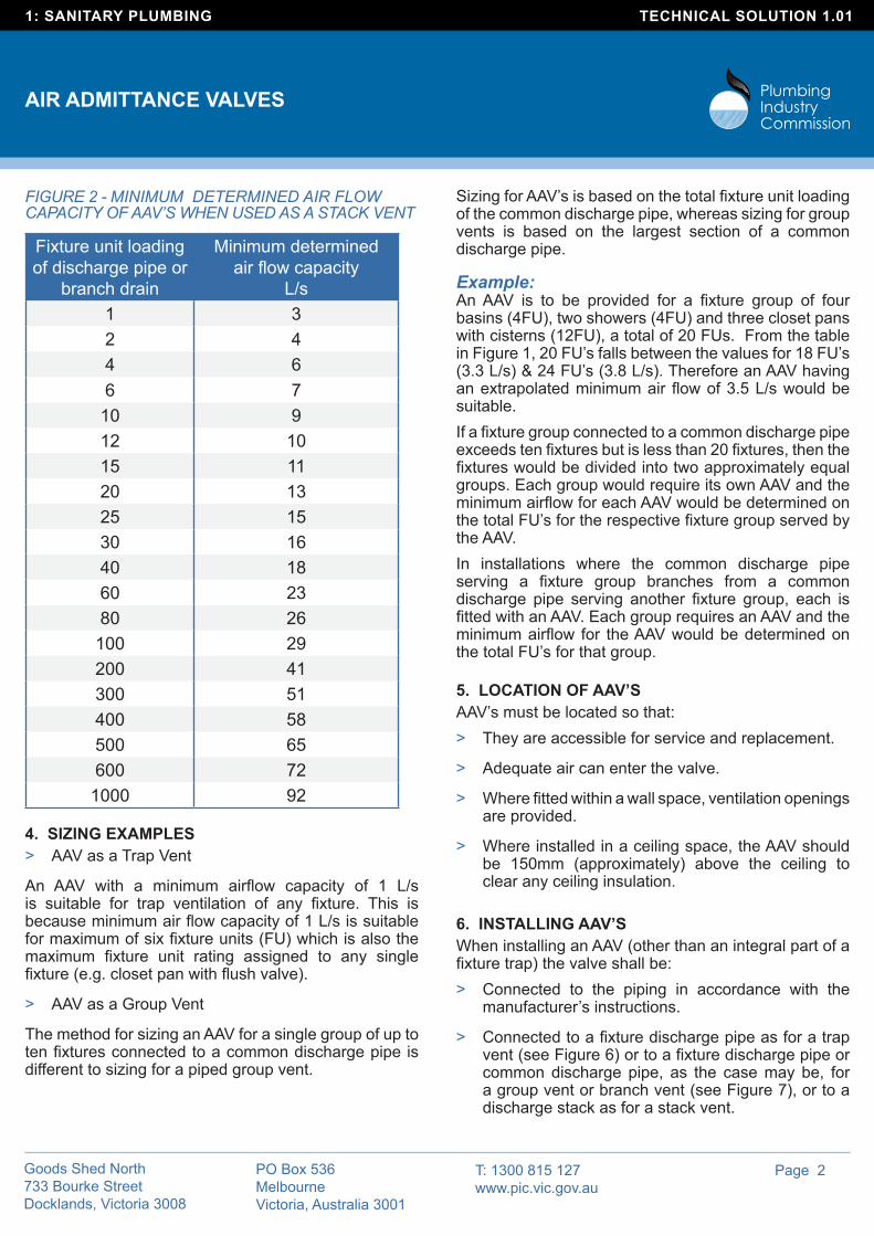
FIGURE 2 - MINIMUM DETERMINED AIR FLOW CAPACITY OF AAV’S WHEN USED AS A STACK VENT
Fixture unit loading of discharge pipe or
branch drain
Minimum determined air flow capacity
L/s1 32 44 66 7
10 912 1015 1120 1325 1530 1640 1860 2380 26
100 29200 41300 51400 58500 65600 72
1000 92
Sizing for AAV’s is based on the total fixture unit loading of the common discharge pipe, whereas sizing for group vents is based on the largest section of a common discharge pipe.
Example: An AAV is to be provided for a fixture group of four basins (4FU), two showers (4FU) and three closet pans with cisterns (12FU), a total of 20 FUs. From the table in Figure 1, 20 FU’s falls between the values for 18 FU’s (3.3 L/s) & 24 FU’s (3.8 L/s). Therefore an AAV having an extrapolated minimum air flow of 3.5 L/s would be suitable. If a fixture group connected to a common discharge pipe exceeds ten fixtures but is less than 20 fixtures, then the fixtures would be divided into two approximately equal groups. Each group would require its own AAV and the minimum airflow for each AAV would be determined on the total FU’s for the respective fixture group served by the AAV. In installations where the common discharge pipe serving a fixture group branches from a common discharge pipe serving another fixture group, each is fitted with an AAV. Each group requires an AAV and the minimum airflow for the AAV would be determined on the total FU’s for that group.
5. LOCATION OF AAV’S AAV’s must be located so that:
> They are accessible for service and replacement.
> Adequate air can enter the valve.
> Where fitted within a wall space, ventilation openings are provided.
> Where installed in a ceiling space, the AAV should be 150mm (approximately) above the ceiling to clear any ceiling insulation.
6. INSTALLING AAV’SWhen installing an AAV (other than an integral part of a fixture trap) the valve shall be:
> Connected to the piping in accordance with the manufacturer’s instructions.
> Connected to a fixture discharge pipe as for a trap vent (see Figure 6) or to a fixture discharge pipe or common discharge pipe, as the case may be, for a group vent or branch vent (see Figure 7), or to a discharge stack as for a stack vent.
T: 1300 815 127 www.pic.vic.gov.au
PO Box 536 Melbourne Victoria, Australia 3001
Goods Shed North 733 Bourke Street Docklands, Victoria 3008
1: SANITARY PLUMBING TECHNICAL SOLUTION 1.01
AIR ADMITTANCE VALVES
Page 3
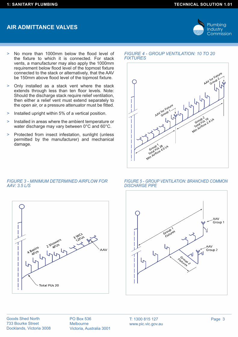
FIGURE 4 - GROUP VENTILATION: 10 TO 20 FIXTURES
FIGURE 5 - GROUP VENTILATION: BRANCHED COMMON DISCHARGE PIPE
> No more than 1000mm below the flood level of the fixture to which it is connected. For stack vents, a manufacturer may also apply the 1000mm requirement below flood level of the topmost fixture connected to the stack or alternatively, that the AAV be 150mm above flood level of the topmost fixture.
> Only installed as a stack vent where the stack extends through less than ten floor levels. Note: Should the discharge stack require relief ventilation, then either a relief vent must extend separately to the open air, or a pressure attenuator must be fitted.
> Installed upright within 5% of a vertical position.
> Installed in areas where the ambient temperature or water discharge may vary between 0°C and 60°C.
> Protected from insect infestation, sunlight (unless permitted by the manufacturer) and mechanical damage.
FIGURE 3 - MINIMUM DETERMINED AIRFLOW FOR AAV: 3.5 L/S
T: 1300 815 127 www.pic.vic.gov.au
PO Box 536 Melbourne Victoria, Australia 3001
Goods Shed North 733 Bourke Street Docklands, Victoria 3008
1: SANITARY PLUMBING TECHNICAL SOLUTION 1.01
AIR ADMITTANCE VALVES
Page 4
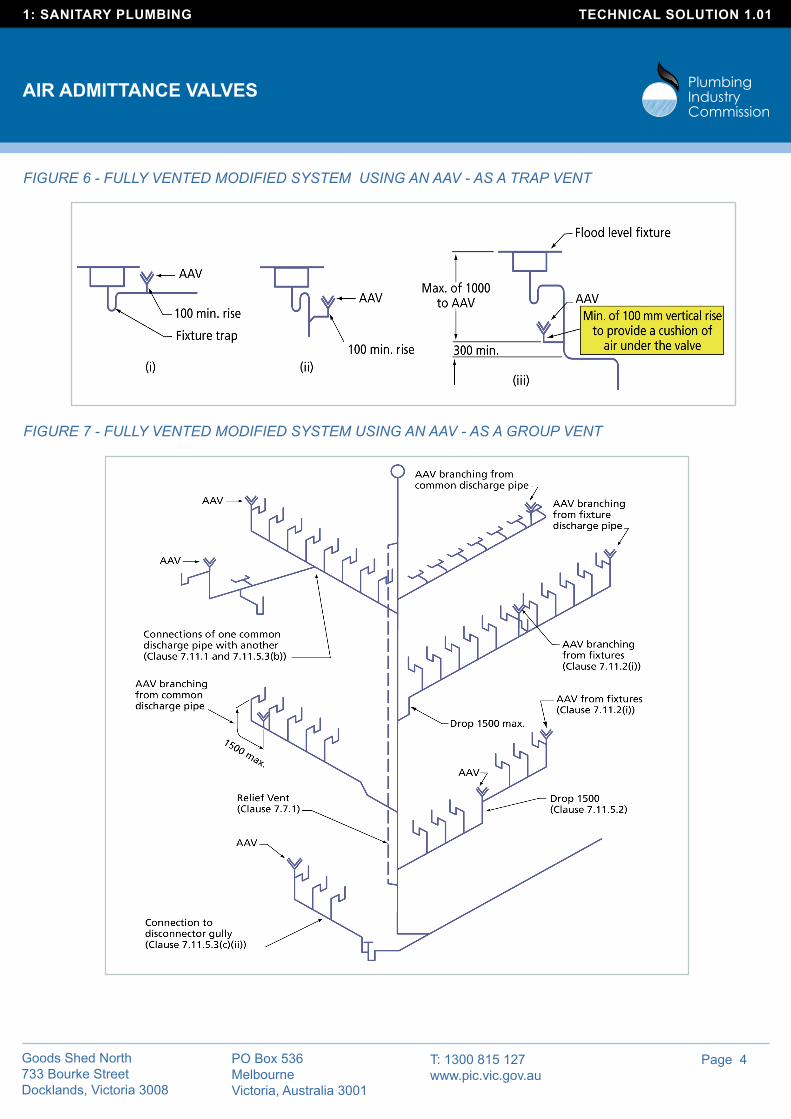
FIGURE 7 - FULLY VENTED MODIFIED SYSTEM USING AN AAV - AS A GROUP VENT
FIGURE 6 - FULLY VENTED MODIFIED SYSTEM USING AN AAV - AS A TRAP VENT

T: 1300 815 127 www.pic.vic.gov.au
PO Box 536 Melbourne Victoria, Australia 3001
Goods Shed North 733 Bourke Street Docklands, Victoria 3008
1: SANITARY PLUMBING TECHNICAL SOLUTION 1.01
AIR ADMITTANCE VALVES
Page 5
FIGURE 8 - FULLY VENTED MODIFIED SYSTEM USING AN AAV - AS A STACK VENT