Embed Size (px)
Citation preview
AIGO 2KAIGO 2K
Australia - Italy Australia - Italy Workshop 2005Workshop 2005
77thth October 2005 October 2005
Pablo Barrigafor AIGO group

ACIGA Mission High Optical Power Test Facility
Low noise 80m base line advanced interferometer
Advanced gravitational wave interferometer (AIGO)
Primary Institutions:University of Adelaide
Australian National University
University of Western Australia
Affiliate Institutions:Monash University
CSIRO-Optics
Development of high power optics in collaboration with LIGO
Demonstrate noise performance of high power interferometer
First in the SouthernHemisphere
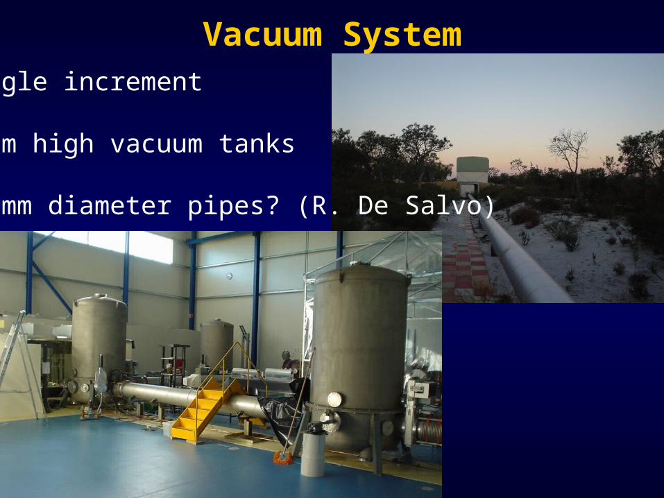
Vacuum SystemSingle increment
3.5m high vacuum tanks
400mm diameter pipes? (R. De Salvo)
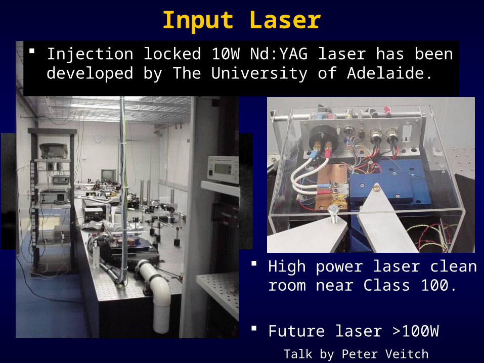
Input Laser Injection locked 10W Nd:YAG laser has been developed
by The University of Adelaide.
High power laser clean room near Class 100.
Future laser >100WTalk by Peter Veitch

10
-110
010
1-200
-150
-100
-50
0
50Horizontal Isolator Transfer Function
Frequency [Hz]
Mag
nitu
de [
dB]
Complete Isolator Transfer Function (Y-Axis)Complete Isolator Transfer Function (X-Axis)
High Optical Power Mode Cleaner Astigmatism and thermal lensing calculations.
Isolation system transfer function shows good performance.
Control system design and implementation underway.
X - Axis
Y - Axis
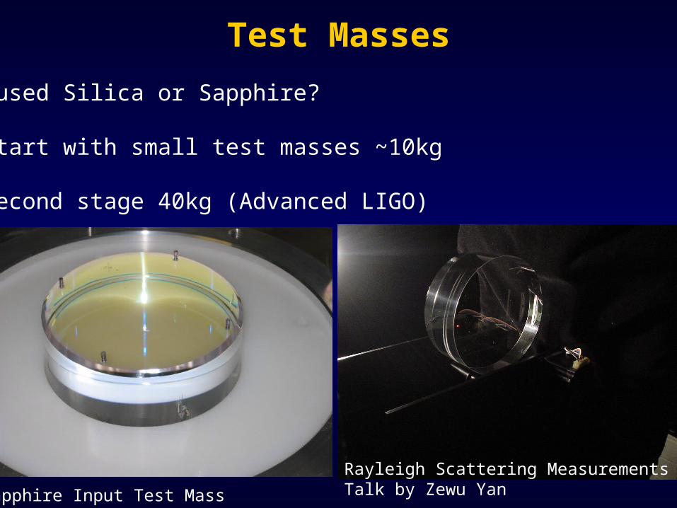
Test Masses
Fused Silica or Sapphire?
Start with small test masses ~10kg
Second stage 40kg (Advanced LIGO)
Sapphire Input Test Mass
Rayleigh Scattering MeasurementsTalk by Zewu Yan
1500.164E+07
.328E+07.492E+07
.656E+07.820E+07
.984E+07.115E+08
.131E+08.150E+08
NODAL SOLUTION
STEP=1SUB =1TIME=1SEQV (AVG)DMX =.752E-05SMN =1472SMX =.350E+08
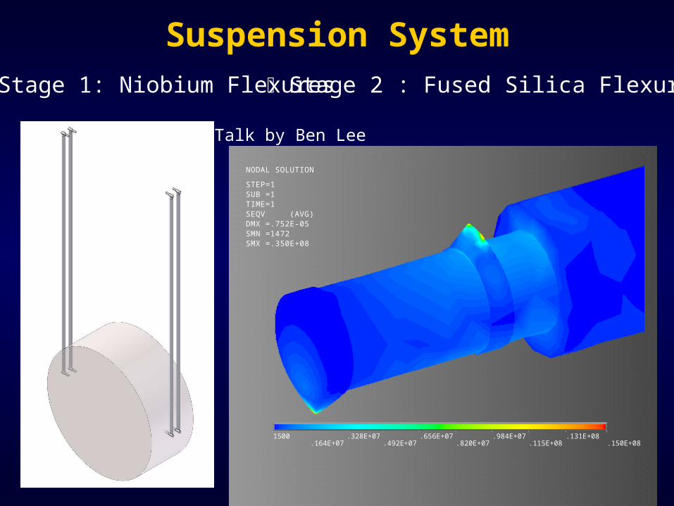
Suspension SystemStage 1: Niobium Flexures Stage 2 : Fused Silica Flexures
Talk by Ben Lee

Isolation System
0.01 0.1 1 10Frequency Hz
400
300
200
100
0
Bd
Frequency Response
Talk by Jean Charles and Eu-Jeen
Robust isolation system
Built for heavy test masses

Digital Control
Digital Control already under development.
DSP based?
LIGO EPICS?
Is there a way of combining both?
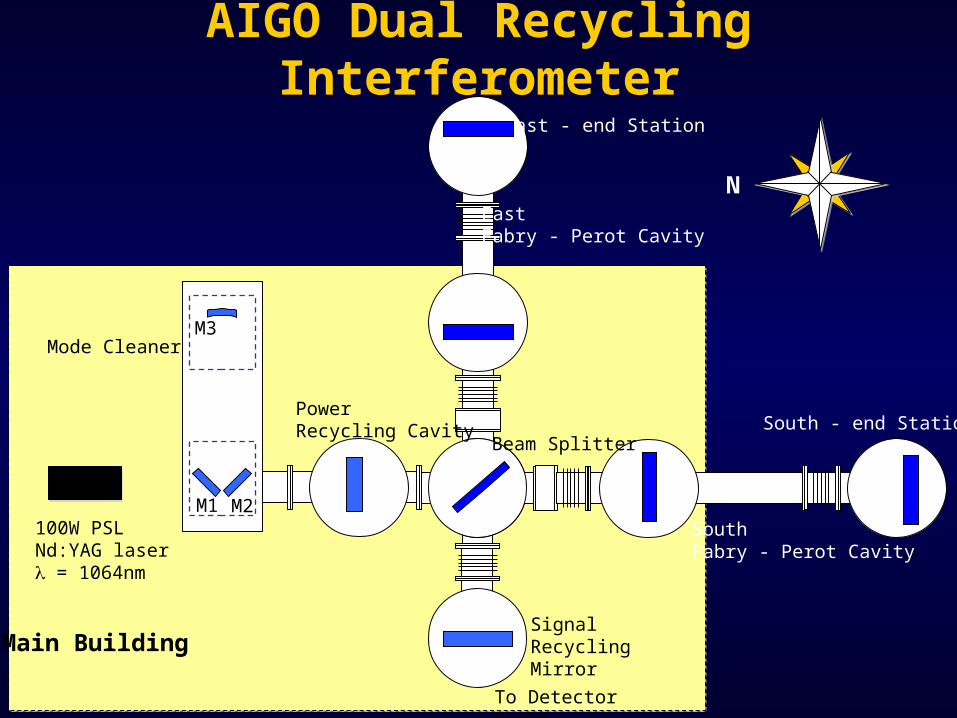
AIGO Dual Recycling Interferometer
M1 M2
M3
To Detector Bench
South Fabry - Perot Cavity
East Fabry - Perot Cavity
Mode Cleaner
100W PSLNd:YAG laser = 1064nm
East - end Station
South - end Station
Main BuildingSignal Recycling Mirror
Beam Splitter
Power Recycling Cavity
N

Mode-Cleaner Geometry
M1 M2
M3
l1200mm
2wo
l 299
00m
m
Incident angle 44.712o
Incident angle 0.579o
Concave end mirror
Flat Mirrors used as input and output couplers
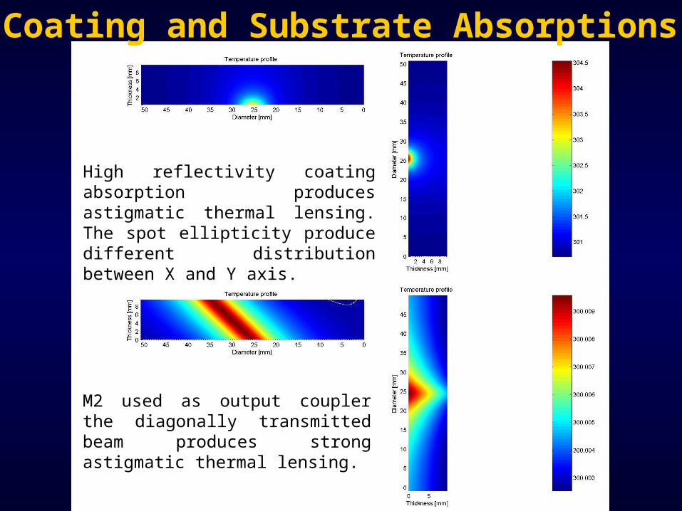
Coating and Substrate Absorptions
High reflectivity coating absorption produces astigmatic thermal lensing. The spot ellipticity produce different distribution between X and Y axis.
M2 used as output coupler the diagonally transmitted beam produces strong astigmatic thermal lensing.
0 20 40 60 80 100 120 140 160 180 200
0
0.02
0.04
0.06
Input Power [W]
Ecc
entr
icity
M3 SpotWaist Size
Input Power [W]
0 20 40 60 80 100 120 140 160 180 2000
0.02
0.04
0.06
Ecc
entr
icity
M3 SpotWaist Size
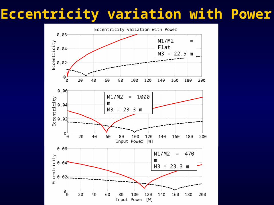
Eccentricity variation with Power
0 20 40 60 80 100 120 140 160 180 2000
0.02
0.04
0.06
Ecc
entr
icity
M3 SpotWaist Size
Eccentricity variation with Power
M1/M2 = FlatM3 = 22.5 m
M1/M2 = 1000 mM3 = 23.3 m
M1/M2 = 470 mM3 = 23.3 m

AIGO Future Interferometer
M1 M2
M3
To Detector Bench
South Fabry - Perot Cavity
East Fabry - Perot Cavity
Mode Cleaner
100W PSLNd:YAG laser = 1064nm
East - end Station
South - end Station
Main BuildingSignal Recycling Mirror
Beam Splitter
Power Recycling Cavity
N

AIGO Future Interferometer
M1 M2
M3
To Detector Bench
South Fabry - Perot Cavity
East Fabry - Perot Cavity
Mode Cleaner
100W PSLNd:YAG laser = 1064nm
East - end Station
South - end Station
Main BuildingSignal Recycling Mirror
Beam Splitter
Power Recycling Cavity
N

AIGO Future Interferometer
M1 M2
To Detector Bench
South Fabry - Perot Cavity
East Fabry - Perot Cavity
Mode Cleaner
100W PSLNd:YAG laser = 1064nm
East - end Station
South - end Station
Main BuildingSignal Recycling Mirror
Beam Splitter
Power Recycling Cavity
N
M3
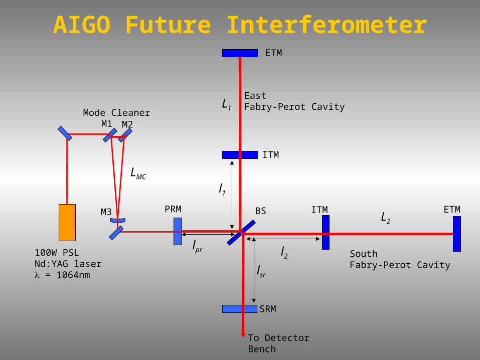
M1 M2
M3
To Detector Bench
South Fabry-Perot Cavity
East Fabry-Perot Cavity
Mode Cleaner
100W PSLNd:YAG laser = 1064nm
ETM
ETM
SRM
BSPRM ITM
ITM
L1
L2
l1
l2
lsr
lpr
LMC
AIGO Future Interferometer
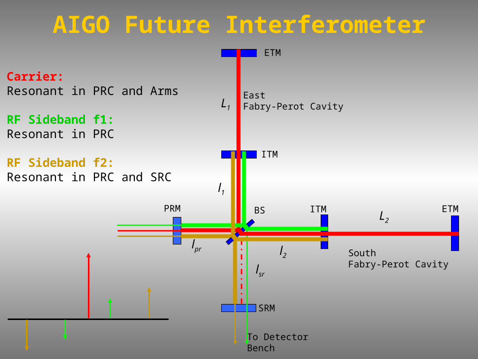
To Detector Bench
South Fabry-Perot Cavity
East Fabry-Perot Cavity
ETM
ETM
SRM
BSPRM ITM
ITM
L1
L2
l1
l2
lsr
lpr
AIGO Future Interferometer
Carrier:Resonant in PRC and Arms
RF Sideband f1:Resonant in PRC
RF Sideband f2:Resonant in PRC and SRC

Actual Interferometer Configuration
Cavities Length
LMC = 10 m
LPRC = 12 m
LArms = 2000 m
LSRC = 12 m
South End Station
East End Station
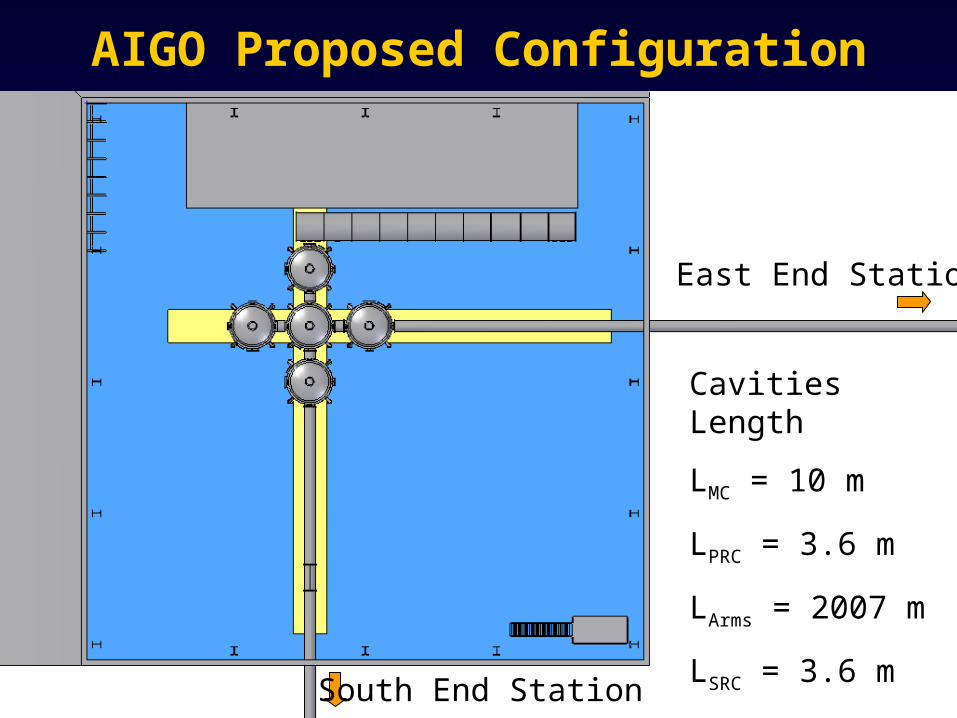
AIGO Proposed Configuration
Cavities Length
LMC = 10 m
LPRC = 3.6 m
LArms = 2007 m
LSRC = 3.6 m
South End Station
East End Station

Rule of Thumb
• Carrier should be resonant in the arms and the PRC.
• Carrier resonant in the SRC for resonant sideband extraction (RSE), and anti-resonant for signal recycling.
• SB1 should be nearly anti-resonant in the arms, and resonant in the PRC.
• SB2 also nearly anti-resonant in the arms, and resonant in the PRC.
• One of the SB should be resonant in the SRC and the other nearly anti-resonant.
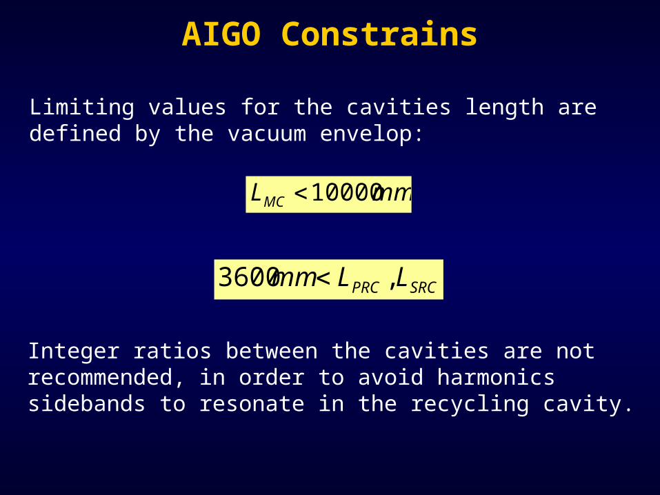
mmLMC 10000
SRCPRC LLmm ,3600
Limiting values for the cavities length are defined by the vacuum envelop:
Integer ratios between the cavities are not recommended, in order to avoid harmonics sidebands to resonate in the recycling cavity.
AIGO Constrains

Actual Configuration
• Length PRC = 11727 mm
Mode Cleaner shorter than Recycling Cavities?
• PRC Free Spectral Range: 12.782 MHz
• PRC as a coupled cavity half integer of PRC FSR
• “Longest” Mode Cleaner 7818 mm FSR = 19.173 MHz
2
21 lllL prPRC

MCm L
cnf
21
For transmission of modulation sidebands by the mode-cleaner, LMC and fm must satisfy:
For sideband coupling into the recycling cavity, LPRC and fm must satisfy:
PRCm L
cnf
22
12
AIGO Interferometer Sidebands
Sideband must not resonate inside the main arms, but also not exactly anti-resonant:
c
Lfn Arm
m
23
Sideband 1 = 19.173 MHz
n1 = 1
n2 = 1
n3 = 255.82

MHzff 20021
To choose the high frequency sideband we look to demodulate at:
Schnupp asymmetry given by:
24 f
cl
AIGO Interferometer Sidebands
For a peak frequency of 300Hz (Adv LIGO) the carrier phase shift will be:
20607.0
Sideband 2 = 172.559 MHz
l = 434 mm
LSRC = 12569 mm

Proposed Configuration
• Length PRC = 4450 mm
• PRC Free Spectral Range: 33.685 MHz
• PRC as a coupled cavity half integer of PRC FSR
• “Longest” Mode Cleaner 8900 mm FSR = 16.842 MHz
2
21 lllL prPRC

MCm L
cnf
21
For transmission of modulation sidebands by the mode-cleaner, LMC and fm must satisfy:
For sideband coupling into the recycling cavity, LPRC and fm must satisfy:
PRCm L
cnf
22
12
AIGO Interferometer Sidebands
Sideband must not resonate inside the main arms, but also not exactly anti-resonant:
c
Lfn Arm
m
23
Sideband 1 = 16.842 MHz
n1 = 1
n2 = 0
n3 = 225.55

MHzff 20021
To choose the high frequency sideband we look to demodulate at:
Schnupp asymmetry given by:
24 f
cl
AIGO Interferometer Sidebands
For a peak frequency of 300Hz (Adv LIGO) the carrier phase shift will be:
20605.0
Sideband 2 = 168.423 MHz
l = 445 mm
LSRC = 5313 mm

Adv LIGO VIRGO AIGO 2K (sh) AIGO 2K (lg)
PRM - BS 4 6 1.8 1.8
BS - ITMInline 4.536 6.4 2.873 10.144
BS - ITMPerp 4.119 5.6 2.427 9.71
L_PRCInline 8.536 12.4 4.673 11.944
L_PRCPerp 8.119 11.6 4.227 11.510
SRM - BS 4.821 5.562 2.663 2.642
AIGO, Adv LIGO and VIRGO
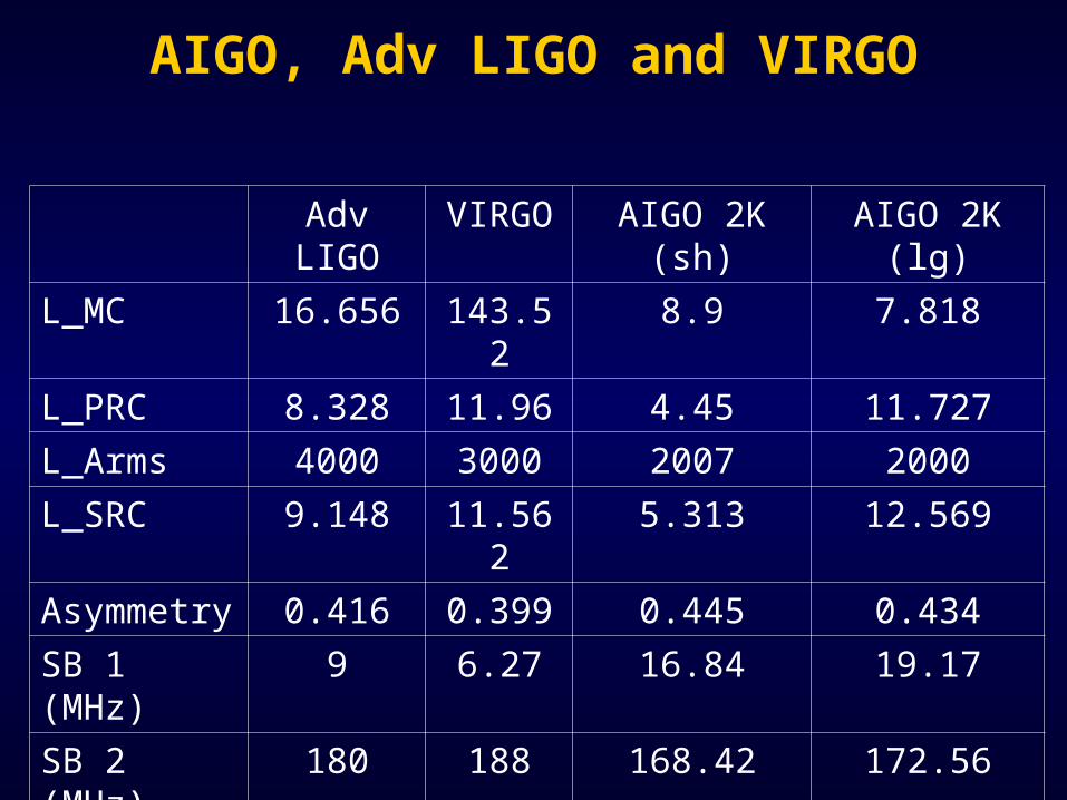
Adv LIGO VIRGO AIGO 2K (sh) AIGO 2K (lg)
L_MC 16.656 143.52 8.9 7.818
L_PRC 8.328 11.96 4.45 11.727
L_Arms 4000 3000 2007 2000
L_SRC 9.148 11.562 5.313 12.569
Asymmetry 0.416 0.399 0.445 0.434
SB 1 (MHz) 9 6.27 16.84 19.17
SB 2 (MHz) 180 188 168.42 172.56
AIGO, Adv LIGO and VIRGO
©LIGO Scientific Collaboration
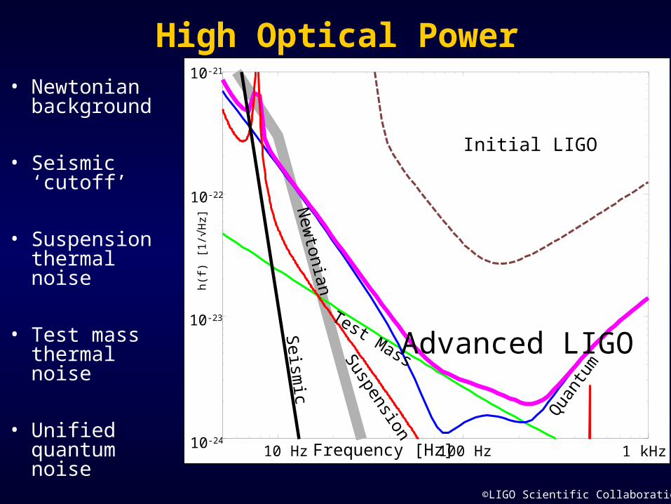
• Newtonian background
• Seismic ‘cutoff’
• Suspension thermal noise
• Test mass thermal noise
• Unified quantum noise
10 Hz 100 Hz 1 kHz
10-22
10-24
10-21
10-23
Initial LIGO
Advanced LIGON
ewtonian
Seism
ic
Suspension
Test Mass
Qua
ntum
Frequency [Hz]
h(f
) [1
/√H
z]
High Optical Power

©LIGO Scientific Collaboration
• Newtonian background
• Seismic ‘cutoff’
• Suspension thermal noise
• Test mass thermal noise
• Unified quantum noise
10 Hz 100 Hz 1 kHz
10-22
10-24
10-21
10-23
Initial LIGO
Advanced LIGON
ewtonian
Seism
ic
Suspension
Test Mass
Qua
ntum
Frequency [Hz]
h(f
) [1
/√H
z]
High Optical Power
AIGO 2KAIGO 2K

Conclusions
AIGO 2K Dual Recycling Interferometer
Test masses Fused Silica or Sapphire?
Digital control system. EPICS, DSP or both?
Short or long Recycling Cavities?
Conclusions
More information at:
ACIGAhttp://www.anu.edu.au/Physics/ACIGA/
Australian National Universityhttp://www.anu.edu.au/Physics/ACIGA/ANU/
University of Adelaidehttp://www.physics.adelaide.edu.au/optics/res/hi_powerc.html
University of Western Australiahttp://www.gravity.pd.uwa.edu.au/