Embed Size (px)
Citation preview
AgilentUnderstanding GeneralPacket Radio Service (GPRS)
Application Note 1377
Increase your knowledge ofGPRS technology. Learn about GPRS:
• networks• protocols• air interface• packet data
transfer methods
2
Page
Data communication needs . . . . . . . . . . . . . . . . . . . . . . . . . . . . . . 4
The GPRS network . . . . . . . . . . . . . . . . . . . . . . . . . . . . . . . . . . . . . 5
GPRS protocol layers . . . . . . . . . . . . . . . . . . . . . . . . . . . . . . . . . . 10
GPRS identities . . . . . . . . . . . . . . . . . . . . . . . . . . . . . . . . . . . . . . 14
GPRS air interface . . . . . . . . . . . . . . . . . . . . . . . . . . . . . . . . . . . .16
Packet data transfer operations . . . . . . . . . . . . . . . . . . . . . . . . . 24
Table of Contents
3
In response to customer demand for wireless Internetaccess—and as a stepping-stone to 3G networks—manyGSM operators are rolling out general packet radio service(GPRS). This technology increases the data rates ofexisting GSM networks, allowing transport of packet-based data. New GPRS handsets will be able to transferdata at rates much higher than the 9.6 or 14.4 kbps currently available to mobile-phone users. Under idealcircumstances, GPRS could support rates to 171.2 kbps,surpassing ISDN access rates. However, a more realisticdata rate for early network deployments is probablyaround 40 kbps using one uplink and three downlink timeslots.
Unlike circuit-switched 2G technology, GPRS is an“always-on” service. It will allow GSM operators to provide high speed Internet access at a reasonable costby billing mobile-phone users for the amount of datathey transfer rather than for the length of time they are connected to the network.
This paper will look in detail at the new protocols, procedures, and other technology changes that GPRSbrings to GSM networks.
Introduction
4
Before examining GPRS technology in detail, let’s reviewsome basic terms of data communications.
Data communication applications generally are dividedinto two categories:
• Real time applications involve small data transactionssuch as sending or receiving a quick e-mail, performinga financial transaction, getting a sports or news update from the web, or chatting on line.
• Data access applications are bulkier and involve sending or receiving large amounts of data. Examples are downloading web pages and files from the Internet or transferring large files to other users.
Two techniques are available for moving data acrosscommunication networks:
Circuit switching is a mode in which a connection (orcircuit) is established from the point of origin of a datatransfer to the destination. Network resources are dedi-cated for the duration of the call until the user breaksthe connection. Using these resources, data can betransmitted or received either continuously or in bursts,depending on the application. Since resources remaindedicated for the entire duration of a data call, the numberof subscribers that the network can support is limited.
Packet switching is a mode in which resources areassigned to a user only when data needs to be sent orreceived. Data is sent in packets, which are routedacross the network along with other user traffic. Thistechnique allows multiple users to share the sameresources, thus increasing capacity on the network andmanaging resources quite effectively. However, the tech-nique does place some limitations on data throughput.
Experience has shown that most data communicationapplications do not require continuous data transfer.Users may need to be connected to a data communica-tion network (such as a LAN, WAN, the Internet, or acorporate Intranet), but that does not mean they aresending and receiving data at all times. Furthermore,data transfer needs generally are not symmetrical. Inmost cases users send out small messages but receivelarge downloads. At any given time, most of the datatransfer is in one direction.
Section 1: Data communication needs
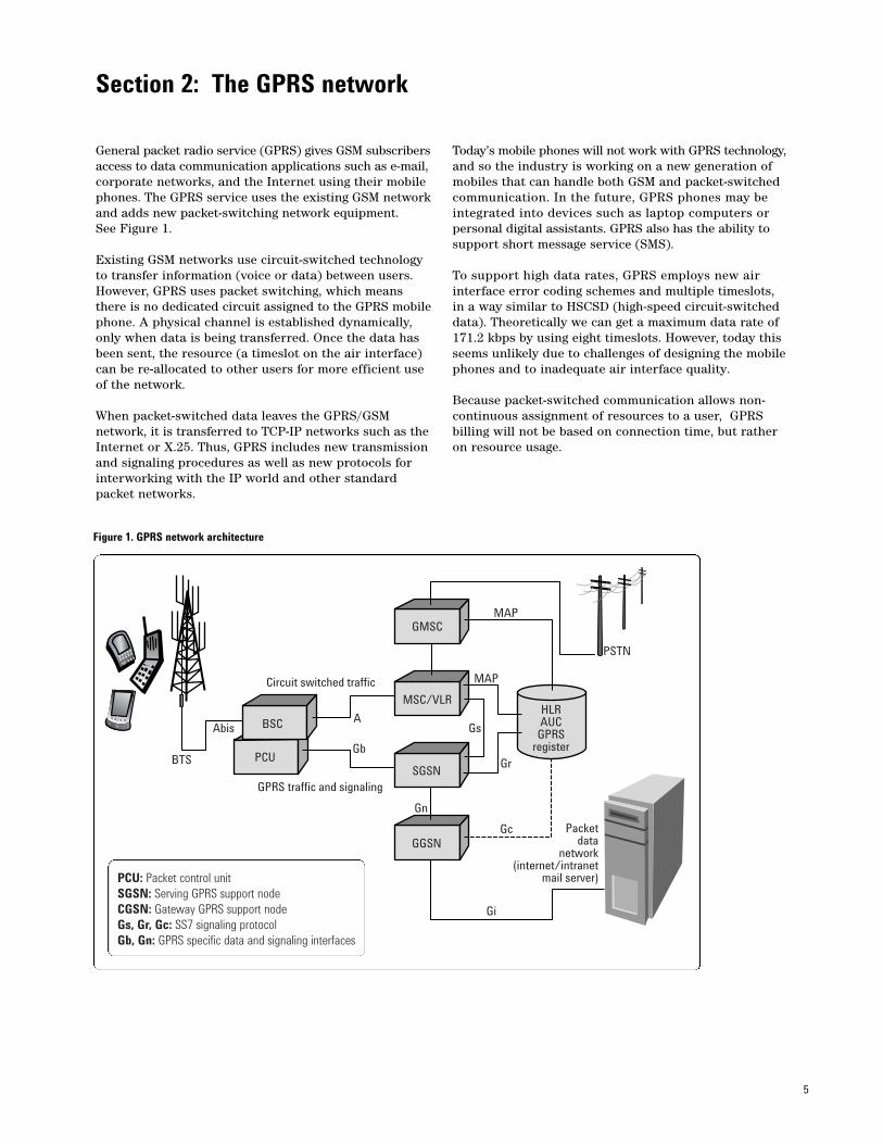
PCU: Packet control unitSGSN: Serving GPRS support nodeCGSN: Gateway GPRS support nodeGs, Gr, Gc: SS7 signaling protocolGb, Gn: GPRS specific data and signaling interfaces
5
General packet radio service (GPRS) gives GSM subscribersaccess to data communication applications such as e-mail,corporate networks, and the Internet using their mobilephones. The GPRS service uses the existing GSM networkand adds new packet-switching network equipment.See Figure 1.
Existing GSM networks use circuit-switched technologyto transfer information (voice or data) between users.However, GPRS uses packet switching, which meansthere is no dedicated circuit assigned to the GPRS mobilephone. A physical channel is established dynamically,only when data is being transferred. Once the data hasbeen sent, the resource (a timeslot on the air interface)can be re-allocated to other users for more efficient useof the network.
When packet-switched data leaves the GPRS/GSM network, it is transferred to TCP-IP networks such as theInternet or X.25. Thus, GPRS includes new transmissionand signaling procedures as well as new protocols forinterworking with the IP world and other standardpacket networks.
Today’s mobile phones will not work with GPRS technology,and so the industry is working on a new generation ofmobiles that can handle both GSM and packet-switchedcommunication. In the future, GPRS phones may beintegrated into devices such as laptop computers or personal digital assistants. GPRS also has the ability tosupport short message service (SMS).
To support high data rates, GPRS employs new air interface error coding schemes and multiple timeslots,in a way similar to HSCSD (high-speed circuit-switcheddata). Theoretically we can get a maximum data rate of171.2 kbps by using eight timeslots. However, today thisseems unlikely due to challenges of designing the mobilephones and to inadequate air interface quality.
Because packet-switched communication allows non-continuous assignment of resources to a user, GPRSbilling will not be based on connection time, but ratheron resource usage.
Section 2: The GPRS network
Figure 1. GPRS network architecture
GMSC
MSC/VLR
SGSN
GGSN
HLRAUC
GPRSregister
BSC
PCUBTS
Abis
Circuit switched traffic
GPRS traffic and signaling
A
Gb
Gs
Gr
Gn
Gi
Packetdata
network(internet/intranet
mail server)
MAP
MAP
Gc
PSTN
6
GPRS network architecture
GPRS technology brings many changes to the existingGSM network. Most of the changes are amendmentsmade by adding new blocks rather than by modifyingexisting resources. A simplified view of this new hybridnetwork shows the elements introduced by GPRS.
The gateway GPRS support node (GGSN) is similar tothe GSM gateway mobile switching center (GMSC) andprovides a gateway between the GPRS network and thepublic packet data network (PDN) or other GPRS networks.The GGSN provides authentication and location manage-ment functions, connects to the home location register(HLR) by means of the Gc interface, and counts thenumber of packets transmitted for accurate subscriber billing.
The serving GPRS support node (SGSN), like the GSM mobile switching center and visitor location register (MSC/VLR), controls the connection betweenthe network and the mobile station (MS). The SGSN provides session management and GPRS mobility management functions such as handovers and paging. It attaches to the HLR via the Gr interface and to theMSC/VLR via the Gs interface. It also counts the number of packets routed.
Functions of the packet control unit (PCU) include converting packet data into a format that can be trans-ferred over the air interface, managing radio resources,and implementing quality of service (QoS) measurements.
The signaling links between the GPRS nodes and theGSM blocks will be SS7 MAP interfaces. The signalingbetween GPRS nodes is defined by the GPRS specifica-tions. New physical interfaces include the Gb interface,which connects the SGSN to the PCU and is usuallylocated in the base station subsystem (BSS); the Gninterface, which connects the GGSN and SGSN; and the Gc, Gr, and Gs interfaces, which carry SS7-based protocols.
7
GPRS mobile phone operation states
Mobile phones go through different states of communi-cation. For example, when a GSM phone camps onto anetwork, the phone enters an idle state in which it usesvery few network resources. When the user makes a callrequest or receives a call, however, the phone goes intothe dedicated state in which it is assigned a continuousresource until the connection is terminated.
The GPRS mobile phones will also have defined states,which are described below.
GPRS idle is the state in which the mobile phone campsonto the GSM network. The phone receives circuit-switched paging and behaves as a GSM phone. Althoughit does not interact with the GPRS network in this state,it still possesses GPRS functionality.
GPRS ready is the state achieved when the GPRSmobile attached itself to the network. In this state themobile phone can activate a packet data protocol (PDP)context, which allows the phone to establish a packettransfer session with external data networks to transmitand receive data packets. Once a PDP context is activated,resource blocks are assigned to the session until datatransfer ceases for a specified period and the mobilephone moves into the standby state.
GPRS standby is a state in which the mobile is connectedto the GPRS network, but no data transmission occurs.If a data packet for the mobile arrives, the network willpage the mobile, which in turn activates a PDP contextsession to the bring the mobile back to the ready state.
GPRS/GSM mobile classes
ETSI defines three different classes of mobiles for thehybrid GPRS/GSM network:
Class A (GSM/GPRS)Class A mobiles can attach to the GPRS and GSM networksimultaneously. They can receive GSM voice/data/SMScalls and GPRS data calls. For this to happen, themobiles must monitor both the GSM and GPRS networks for incoming calls. Class A mobiles also canmake and receive GPRS and GSM calls simultaneously.Operational requirements of this class include an additional receiver in the mobile phone for neighbor cell measurements.
Class B (GSM/GPRS)This class is similar to class A with the exception thatClass B mobile phones will not support simultaneoustraffic. If a GPRS call is ON, the phone cannot receiveGSM calls and vice versa.
Class C (GSM or GPRS)This class of mobile phones will have both GSM andGPRS functionality but will attach to only one networkat a time. Thus, if the phone is attached to the GPRSnetwork, it will be detached from the GSM network and will not be able to make or receive GSM calls.Conversely, if it is attached to the GSM network, it will not be able to make or receive GPRS calls.
Today most manufacturers are building Class B phones.
8
The GPRS attach procedure
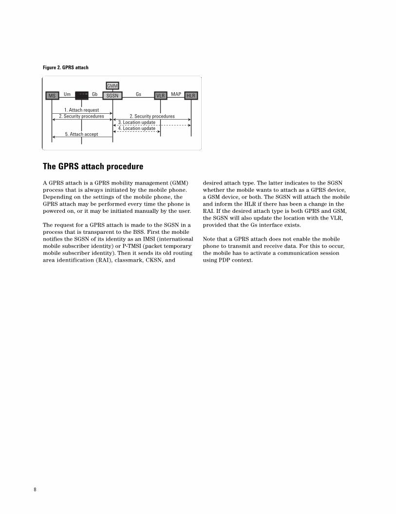
A GPRS attach is a GPRS mobility management (GMM)process that is always initiated by the mobile phone.Depending on the settings of the mobile phone, theGPRS attach may be performed every time the phone ispowered on, or it may be initiated manually by the user.
The request for a GPRS attach is made to the SGSN in aprocess that is transparent to the BSS. First the mobilenotifies the SGSN of its identity as an IMSI (internationalmobile subscriber identity) or P-TMSI (packet temporarymobile subscriber identity). Then it sends its old routingarea identification (RAI), classmark, CKSN, and
desired attach type. The latter indicates to the SGSN whether the mobile wants to attach as a GPRS device, a GSM device, or both. The SGSN will attach the mobileand inform the HLR if there has been a change in theRAI. If the desired attach type is both GPRS and GSM,the SGSN will also update the location with the VLR,provided that the Gs interface exists.
Note that a GPRS attach does not enable the mobilephone to transmit and receive data. For this to occur,the mobile has to activate a communication sessionusing PDP context.
Figure 2. GPRS attach
MS Um Gb Gs MAPBSS VLR HLRSGSN
GMM
1. Attach request2. Security procedures 2. Security procedures
3. Location update
5. Attach accept4. Location update
9
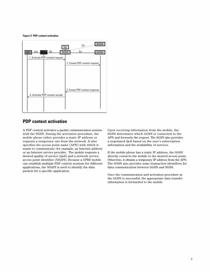
PDP context activation
A PDP context activates a packet communication sessionwith the SGSN. During the activation procedure, themobile phone either provides a static IP address orrequests a temporary one from the network. It also specifies the access point name (APN) with which itwants to communicate—for example, an Internet addressor an Internet service provider. The mobile requests adesired quality of service (QoS) and a network serviceaccess point identifier (NSAPI). Because a GPRS mobilecan establish multiple PDP context sessions for differentapplications, the NSAPI is used to identify the datapackets for a specific application.
Upon receiving information from the mobile, the SGSN determines which GGSN is connected to the APN and forwards the request. The SGSN also provides a negotiated QoS based on the user’s subscriptioninformation and the availability of services.
If the mobile phone has a static IP address, the GGSNdirectly connects the mobile to the desired access point.Otherwise, it obtains a temporary IP address from the APN.The GGSN also provides some transaction identifiers fordata communication between GGSN and SGSN.
Once the communication and activation procedure atthe GGSN is successful, the appropriate data transferinformation is forwarded to the mobile.
Figure 3. PDP context activation
MS Um Gb Gs
Gs
BSS SGSN GGSN
GGSNSM
1. Activate PDP context request
2. Create PDP context request
3. Create PDP context response
4. Activate PDP context accept
10
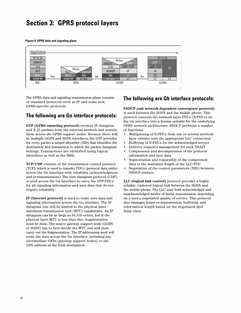
The GPRS data and signaling transmission plane consistsof standard protocols such as IP and some new, GPRS-specific protocols.
The following are Gn interface protocols:
GTP (GPRS tunneling protocol) receives IP datagramand X.25 packets from the external network and tunnelsthem across the GPRS support nodes. Because there willbe multiple GGSN and SGSN interfaces, the GTP providesfor every packet a tunnel identifier (TID) that identifies thedestination and transaction to which the packet/datagrambelongs. Transactions are identified using logical identifiers as well as the IMSI.
TCP/UDP consists of the transmission control protocol(TCP), which is used to transfer PDUs (protocol data units)across the Gn interface with reliability (acknowledgmentand re-transmissions). The user datagram protocol (UDP),is used across the Gn interface to carry the GTP-PDUsfor all signaling information and user data that do notrequire reliability.
IP (Internet protocol) is used to route user data andsignaling information across the Gn interface. The IPdatagram size will be limited to the physical layer - maximum transmission unit (MTU) capabilities. An IPdatagram can be as large as 65,535 octets, but if thephysical layer MTU is less than this, fragmentation must be done. The source gateway support node (GGSN or SGSN) has to first decide the MTU size and thencarry out the fragmentation. The IP addressing used willroute the data across the Gn interface, including anyintermediate GSNs (gateway support nodes), to the GSN address at the final destination.
The following are Gb interface protocols:
SNDCP (sub network dependent convergence protocol)is used between the SGSN and the mobile phone. Thisprotocol converts the network layer PDUs (N-PDUs) onthe Gn interface into a format suitable for the underlyingGPRS network architecture. SNDCP performs a numberof functions:• Multiplexing of N-PDUs from one or several network-
layer entities onto the appropriate LLC connection• Buffering of N-PDUs for the acknowledged service• Delivery sequence management for each NSAPI• Compression and decompression of the protocol
information and user data• Segmentation and reassembly of the compressed
data to the maximum length of the LLC-PDU • Negotiation of the control parameters (XID) between
SNDCP entities.
LLC (logical link control) protocol provides a highlyreliable, ciphered logical link between the SGSN and the mobile phone. The LLC uses both acknowledged andunacknowledged modes of frame transmission, dependingon a user’s negotiated quality of service. This protocolalso manages frame re-transmission, buffering, andinformation length based on the negotiated QoS delay class.
Section 3: GPRS protocol layers
Figure 4. GPRS data and signaling plane
IP/X.25 IP/X.25
IP IP
SNDCP SNDCP
BSSGP BSSGP
UDP/TCP UDP/TCPLLC LLC
RLC RLC
GTPGTP
MAC MAC NS NSL1 bis L1 bis L1 L1 L1
L2 L2
L2
GSM RF GSM RF
Relay
Relay
Um Gb Gn
MS BSS SGSN GGSN
Application
11
BSSGP (base station system GPRS protocol) routesinformation between the SGSN and the BSS. This protocolconveys QoS information but does not carry out any formof error correction. Its primary function is to provideradio-related information for use by the radio link control (RLC) and medium access control (MAC) functions on the air interface.
The LLC layer uses the services of the BSSGP for datatransfer. The relay function at the BSS transfers LLCframes between the RLC/MAC layer and the BSSGPlayer. The BSSGP sends information to the network services layers to determine the transfer destination:• BVCI (BSSGP virtual connection identifier)
is sent to the network services layers for routing signaling and data information to the correct peer functional entities. Each BVCI between two peer entities is unique.
• LSP (link selection parameter) is used in conjunction with the BVCI to aid in selecting a physical link for the load-sharing process.
• NSEI (network service entity identifier) used at the BSS and the SGSN provides the network management functionality required for operation ofthe Gb interface. The NSEI together with the BVCIuniquely identifies a BSSGP virtual connection.
NS (network service) layer uses frame relay across the Gb interface and could be a point-to-point connectionbetween the SGSN and the BSS or a frame relay network. The NS layer uses a DLCI (data link connectionidentifier) look-up table to indicate the routing pathbetween the SGSN and the BSS. The initial value of theDLCI field is derived from the BVCI, NSEI, and LSP supplied by the BSSGP layer. This value changes as the frame passes through the frame relay network and reaches its final destination.
The following are Um interface protocols:
RLC (radio link control) is responsible for a number of functions:• Transferring LLC-PDUs between the LLC layer
and the MAC function• Segmentation of LLC-PDUs into RLC data blocks
and re-assembly of RLC data blocks to fit into TDMA frame blocks
• Segmentation and re-assembly of RLC/MAC control messages into RLC/MAC control blocks
• Backward error correction for selective transmission of RLC data blocks.
The RLC segmentation function is a process of takingone or more LLC-PDUs and dividing them into smallerRLC blocks. The LLC-PDUs are known collectively as a temporary block flow (TBF) and are allocated theresources of one or more packet data channels (PDCH).The TBF is temporary and is maintained only for theduration of the data transfer. Each TBF is assigned atemporary flow identity (TFI) by the network.
The RLC data blocks consist of an RLC header, an RLCdata unit, and spare bits. The RLC data block along witha MAC header may be encoded using one of four definedcoding schemes. The coding scheme is critical in decidingthe segmentation process.
MAC (medium access control) controls the access signaling across the air interface, including the manage-ment of shared transmission resources (assignment ofthe radio block to multiple users on the same timeslot).MAC achieves these functionalities by placing a headerin front of the RLC header in the RLC/MAC data andcontrol blocks. The MAC header contains several elements, some of which are direction-specific, referring to the downlink or uplink.
The key parameters of MAC header are:• Uplink status flag (USF), is sent in all downlink
RLC/MAC blocks and indicates the owner or use of the next uplink radio block on the same timeslot.
• Relative reserved block period (RRBP), identifies a single uplink block in which the mobile phone will transmit control information.
• Payload type (PT), the type of data (control block or data block) contained in the remainder of the RLC/MAC block.
• Countdown value (CV), is sent by the mobile to allow the network to calculate the number of RLC data blocks remaining in the current uplink TBF.
12
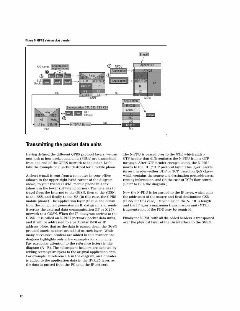
Transmitting the packet data units
Having defined the different GPRS protocol layers, we cannow look at how packet data units (PDUs) are transmittedfrom one end of the GPRS network to the other. Let’stake the example of a packet destined for a mobile phone.
A short e-mail is sent from a computer in your office(shown in the upper right-hand corner of the diagramabove) to your friend’s GPRS mobile phone in a taxi(shown in the lower right-hand corner). The data has totravel from the Internet to the GGSN, then to the SGSN,to the BSS, and finally to the MS (in this case, the GPRSmobile phone). The application layer (that is, the e-mailfrom the computer) generates an IP datagram and sendsit across the external data communication (IP or X.25)network to a GGSN. When the IP datagram arrives at theGGSN, it is called an N-PDU (network packet data unit),and it will be addressed to a particular IMSI or IPaddress. Note, that as the data is passed down the GGSNprotocol stack, headers are added at each layer. Whilemany successive headers are added in this manner, thediagram highlights only a few examples for simplicity.Pay particular attention to the reference letters in thediagram (A - E). The subsequent headers are denoted byadding rectangular layers to the original application data.For example, at reference A in the diagram, an IP headeris added to the application data in the IP/X.25 layer, asthe data is passed from the PC onto the IP network.
The N-PDU is passed over to the GTP, which adds a GTP header that differentiates the N-PDU from a GTPmessage. After GTP header encapsulation, the N-PDUmoves to the UDP/TCP protocol layer. This layer insertsits own header—either UDP or TCP, based on QoS class—which contains the source and destination port addresses,routing information, and (in the case of TCP) flow control.(Refer to B in the diagram.)
Now the N-PDU is forwarded to the IP layer, which addsthe addresses of the source and final destination GSN(SGSN for this case). Depending on the N-PDU’s lengthand the IP layer’s maximum transmission unit (MTU),fragmentation of the PDU may be required.
Finally the N-PDU with all the added headers is transportedover the physical layer of the Gn interface to the SGSN.
Figure 5. GPRS data packet transfer
Application
Application
Application
NPDU
SGSN GGSN
GnGb
MsBSS
RLCBlocks
LLCBlocks
1520 octets Compressionsegmentation
SNDCP
SNDCP
UDP/TCP UDP/TCP
BSSGP
BSSGP
GTPLLC
LLC
NS
NS
IP
L2L1
IP
L2
L2
L1 L1L1 bis
L1 bis
IP/X.25
IP/X.25
GTP
Segmentation CS1, CS2, CS3, CS4
4 TDMA Bursts
RLCMAC
RLC
MACGSM RF GSM RF
Um
A
BC
D
E
Application
Relay
Relay
13
Transmission at the SGSN
At the SGSN, the headers are removed and the N-PDU isrelayed to the SNDCP. This protocol layer will compress(optionally) and segment the packet in order to meet theMTU requirement of 1520 octets for transmission overthe frame-relay network services (NS) layer on the Gbinterface. Then the SNDCP will first classify the N-PDUas either a connection-oriented SN-DATA PDU or a con-nectionless SN-UNITDATA PDU. Finally it will add anSNDCP header containing compression and segmenta-tion information and send the PDU to the LLC layerbelow. (Refer to C in the diagram on page 12.)
The primary function of the LLC layer, as discussed earlier, is to provide a highly reliable logical connectionbetween the SGSN and the mobile phone. The LLC layerhere behaves like the LAPD and LAPDm layers of theGSM Abis and Um interfaces. The layer encapsulates theSN-DATA or SN-UNITDATA PDU in an LLC frame withits own header. The LLC frame containing the SN-PDUnow can be called the LLC block. The LLC header addscontrol information (used for acknowledged-mode frametransfer), frame check sequence, and SAPI values. TheSAPI in this case refers to the service associated withthe LLC frame for this PDP session. The services for thisframe could be mobility management (MM) or user datalevels 1 through 5 (levels of QoS parameters such asdelay, re-transmission, and buffer size). These levels ofservice are decided in the QoS negotiation process.(Refer to D in the diagram on page 12.)
The BSSGP layer below the LLC layer now providessome routing information to the NS layer to route theLLC block over the frame relay physical layer. TheBSSGP also adds a header to the LLC block, which contains some essential information for the RLC/MAClayers of the air interface regarding the block’s transmis-sion including parameters such as priority, TLLI (temporary logical link identifier), etc.
Transmission at the BSS
The data is sent over the physical layer connectionbetween the SGSN and BSS. Next the BSSGP at the BSSsends all of this information to the radio link control(RLC). The most important job of the RLC layer is segmentation of LLC blocks into smaller RLC blocks. A group of LLC blocks, which has been segmented intosmaller blocks, is known as a TBF (temporary blockflow). Each TBF is allocated resources on the air interface on one of more packet data traffic channels(PDTCH). As noted earlier, the TBF is temporary andmaintained only for the duration of the data transfer.The TBF is assigned a TFI (temporary flow identity),and the RLC layer adds a header to the data blocks containing the TFI, RLC block sequence number, lastblock indication, TLLI, and other information. The RLCheader includes direction (downlink/uplink) informa-tion as well. (Refer to E in the diagram on page 12.)
One determination that must be made is the “size” ofinformation inside the RLC data blocks (in other words,the size of the segments of the LLC blocks convertedinto RLC blocks). The LLC data block segment size willdepend on the coding scheme used on the air interface.There are four coding schemes defined for GPRS: CS1,CS2, CS3, and CS4, which contain maximum data of 22,32, 38, and 52 octets correspondingly. The selection ofcoding scheme depends upon trade-off between desiredthroughput and reliability. We will talk more about thesecoding schemes later.
Transmission over the air interface
After the RLC segmentation and header insertions, theRLC blocks are transmitted over the air interface.
It is interesting to note that there is one more layerbefore the physical radio interface—the MAC (mediumaccess control). This layer controls the access signaling,including assignment of uplink and downlink blocks. Itadds its own header, which is monitored by the mobilephones. We’ll discuss this more in a later section onpacket data transfer operations.
The data is transmitted over the air interface to themobile phone (MS) via the physical layer (GSM RF). The data then moves up the MS protocol stack wherethe headers are stripped off at each successive layer.Finally, the original e-mail message is received at theapplication layer by the mobile user.
14
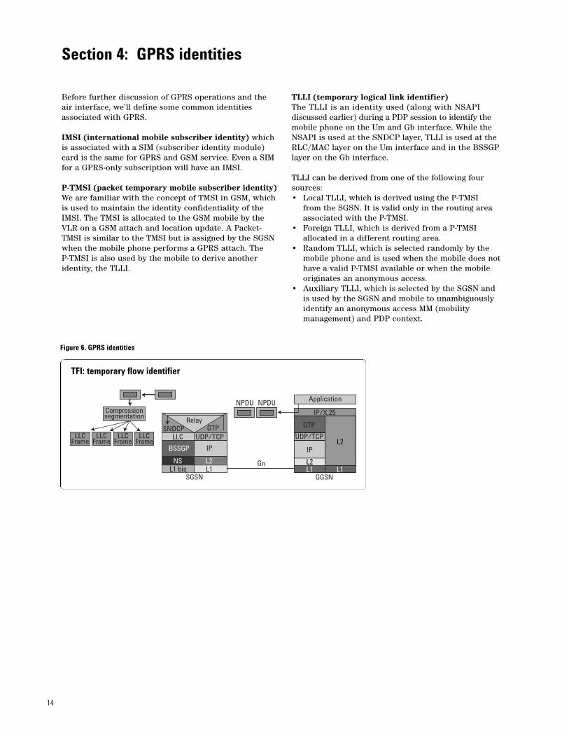
Before further discussion of GPRS operations and theair interface, we’ll define some common identities associated with GPRS.
IMSI (international mobile subscriber identity) whichis associated with a SIM (subscriber identity module)card is the same for GPRS and GSM service. Even a SIMfor a GPRS-only subscription will have an IMSI.
P-TMSI (packet temporary mobile subscriber identity)We are familiar with the concept of TMSI in GSM, whichis used to maintain the identity confidentiality of theIMSI. The TMSI is allocated to the GSM mobile by theVLR on a GSM attach and location update. A Packet-TMSI is similar to the TMSI but is assigned by the SGSNwhen the mobile phone performs a GPRS attach. The P-TMSI is also used by the mobile to derive anotheridentity, the TLLI.
TLLI (temporary logical link identifier) The TLLI is an identity used (along with NSAPI discussed earlier) during a PDP session to identify themobile phone on the Um and Gb interface. While theNSAPI is used at the SNDCP layer, TLLI is used at theRLC/MAC layer on the Um interface and in the BSSGPlayer on the Gb interface.
TLLI can be derived from one of the following foursources:• Local TLLI, which is derived using the P-TMSI
from the SGSN. It is valid only in the routing area associated with the P-TMSI.
• Foreign TLLI, which is derived from a P-TMSI allocated in a different routing area.
• Random TLLI, which is selected randomly by the mobile phone and is used when the mobile does not have a valid P-TMSI available or when the mobile originates an anonymous access.
• Auxiliary TLLI, which is selected by the SGSN and is used by the SGSN and mobile to unambiguously identify an anonymous access MM (mobility management) and PDP context.
Section 4: GPRS identities
Figure 6. GPRS identities
SGSN
SNDCPUDP/TCP
BSSGP
GTPLLC
NS
IP
L2L1L1 bis
Application
GGSN
UDP/TCP
IP
L2
L2
L1 L1
IP/X.25
GTP
Compressionsegmentation
NPDU NPDU
LLCFrame
LLCFrame
LLCFrame
LLCFrame
Gn
Relay
TFI: temporary flow identifier
15
TBF (temporary block flow)The physical connection between the MS and the BSSfor the duration of the link of packet data transfer iscalled the temporary block flow (TBF). The most impor-tant job of the RLC layer is segmentation. As describedearlier, the RLC layer takes one or more LLC blocks andsegments them into smaller RLC blocks. These LLCblocks together are known as a TBF (temporary blockflow). Thus, a TBF is a physical connection used by thetwo radio resource entities to support the unidirectionaltransfer of LLC PDUs on packet data physical channels.All of the LLC frames that have been segmented for oneNPDU (network packet data unit) form one TBF on thelogical link on the air interface. Each TBF is allocatedresources on the air interface on one or more packetdata traffic channels (PDTCH). The TBF is temporaryand is maintained only for the duration of the datatransfer. The TBF is “open” during the data transfer and “closed” when the transfer is discontinued.
TFI (temporary flow identifier)Each TBF is assigned a TFI (temporary flow identity),which is allocated to a mobile for both uplink and downlink packet transfer. This TFI is unique among concurrent TBFs in one direction and is used in place of the MS identity at the RLC/MAC layer. The same TFIvalue can be assigned to concurrent TBFs in the oppositedirection. A resource assignment message containing theTFI precedes the transfer to or from the MS of the LLCframes belonging to one TBF. To address the peer RLCentities, the same TFI is included in every RLC headerbelonging to the TBF as well as in the control messageassociated with the LLC frame transfer (for example,acknowledgments). Since a TFI comprises a five bitfield, values from 0 to 31 are possible.
USF (uplink status flag)The USF, which is transmitted in the RLC/MAC headerof the downlink RLC block, tells the mobile which uplinkresources to use. Multiple users can be multiplexed onthe same timeslot, transmitting only when the USF indi-cates their turn. The mobile monitors the USFs on theallocated PDCHs and transmits radio blocks on thosethat currently bear the USF value reserved for MS usage.
RAI (routing area identity)A subset of a location area, the RAI is a unique identity similar to the LAI (location area identity). When a mobile moves from one routing area to another,it performs routing area updates via the SGSN. An SGSNmay control one or more routing areas. Since a GGSNcan have links to several SGSNs, the SGSN in which themobile currently resides must be identified so that packetscan be routed correctly. For this reason the mobile performs the routing area update when it enters a newrouting area, and if that area belongs to a differentSGSN, a new RAI for the MS is sent to the HLR (homelocation register) for communicating with the GGSN. If aPDP session is active, then PDP update information alsois sent. The routing area identity consists of the MCC(mobile country code), the MNC (mobile network code),the LAC (location area code), and the RAC (routing area code).
16
Now we turn our attention to the GPRS air interface. Itis important to note that GPRS uses the existing GSMresources—spectrum, channels (200 kHz), and timeslots.GPRS users will share the same TDMA frame with GSMvoice users, thus increasing capacity requirements. To acertain extent, GPRS takes care of increased capacitydemand by multiplexing multiple users on the samephysical channels (timeslots). Additionally, the GPRS airinterface will dynamically allocate resources (timeslots)for voice and PDCH (packet data channels). Certainphysical channels will be configured for packet data use,but can be re-configured for voice if needed.
GPRS must allocate resources for signaling and trafficcontrol. Since GPRS has its own set of parameters fornetwork access and call control, it needs separate channelsfor broadcast common control functions (such as paging,random access, and access grant) and associated traffic(similar to SACCH). Some of the signaling channels canbe multiplexed with the GSM channels by using differentpossible channel configurations.
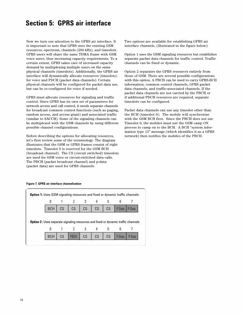
Before describing the options for allocating resources,let’s first review some of the terminology. The diagramillustrates that the GSM or GPRS frames consist of eighttimeslots. Timeslot 0 is reserved for the GSM BCH(broadcast channel). The CS (circuit switched) timeslotsare used for GSM voice or circuit-switched data calls.The PBCH (packet broadcast channel) and p-data (packet data) are used for GPRS channels.
Two options are available for establishing GPRS airinterface channels, (illustrated in the figure below):
Option 1 uses the GSM signaling resources but establishesseparate packet data channels for traffic control. Trafficchannels can be fixed or dynamic.
Option 2 separates the GPRS resources entirely fromthose of GSM. There are several possible configurationswith this option. A PBCH can be used to carry GPRS-BCHinformation, common control channels, GPRS packetdata channels, and traffic-associated channels. If thepacket data channels are not carried by the PBCH or if additional PDCH resources are required, separatetimeslots can be configured.
Packet data channels can use any timeslot other thanthe BCH (timeslot 0). The mobile will synchronize with the GSM BCH first. Since the PBCH does not useTimeslot 0, the mobiles must use the GSM camp ONprocess to camp on to the BCH. A BCH “system infor-mation type 13” message (which identifies it as a GPRSnetwork) then notifies the mobiles of the PBCH.
Section 5: GPRS air interface
Figure 7. GPRS air interface channelization
BCH CS CS CS CS CS P-Data P-Data
BCH CS PBCH CS CS CS P-Data P-Data
0 1 2 3 4 5 6 7
0 1 2 3 4 5 6 7
Option 1: Uses GSM signaling resources and fixed or dynamic traffic channels
Option 2 : Uses separate signaling resources and fixed or dynamic traffic channels
17
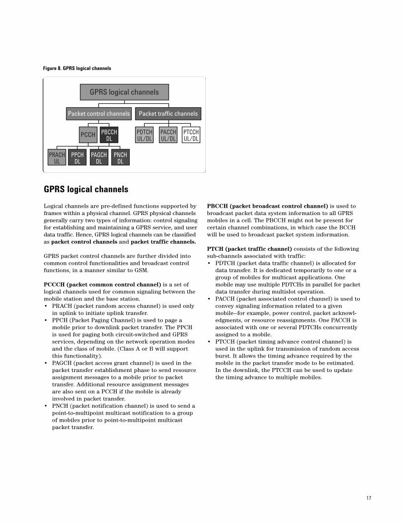
GPRS logical channels
Logical channels are pre-defined functions supported byframes within a physical channel. GPRS physical channelsgenerally carry two types of information: control signalingfor establishing and maintaining a GPRS service, and userdata traffic. Hence, GPRS logical channels can be classifiedas packet control channels and packet traffic channels.
GPRS packet control channels are further divided intocommon control functionalities and broadcast controlfunctions, in a manner similar to GSM.
PCCCH (packet common control channel) is a set oflogical channels used for common signaling between themobile station and the base station.• PRACH (packet random access channel) is used only
in uplink to initiate uplink transfer.• PPCH (Packet Paging Channel) is used to page a
mobile prior to downlink packet transfer. The PPCH is used for paging both circuit-switched and GPRS services, depending on the network operation modes and the class of mobile. (Class A or B will support this functionality).
• PAGCH (packet access grant channel) is used in the packet transfer establishment phase to send resourceassignment messages to a mobile prior to packet transfer. Additional resource assignment messages are also sent on a PCCH if the mobile is already involved in packet transfer.
• PNCH (packet notification channel) is used to send a point-to-multipoint multicast notification to a group of mobiles prior to point-to-multipoint multicast packet transfer.
PBCCH (packet broadcast control channel) is used tobroadcast packet data system information to all GPRSmobiles in a cell. The PBCCH might not be present forcertain channel combinations, in which case the BCCHwill be used to broadcast packet system information.
PTCH (packet traffic channel) consists of the followingsub-channels associated with traffic:• PDTCH (packet data traffic channel) is allocated for
data transfer. It is dedicated temporarily to one or a group of mobiles for multicast applications. One mobile may use multiple PDTCHs in parallel for packetdata transfer during multislot operation.
• PACCH (packet associated control channel) is used toconvey signaling information related to a given mobile—for example, power control, packet acknowl-edgments, or resource reassignments. One PACCH is associated with one or several PDTCHs concurrently assigned to a mobile.
• PTCCH (packet timing advance control channel) is used in the uplink for transmission of random accessburst. It allows the timing advance required by the mobile in the packet transfer mode to be estimated. In the downlink, the PTCCH can be used to update the timing advance to multiple mobiles.
Figure 8. GPRS logical channels
GPRS logical channels
Packet control channels Packet traffic channels
PCCH PBCCHDL
PRACHUL
PAGCHDL
PNCHDL
PPCHDL
PDTCHUL/DL
PACCHUL/DL
PTCCHUL/DL
18
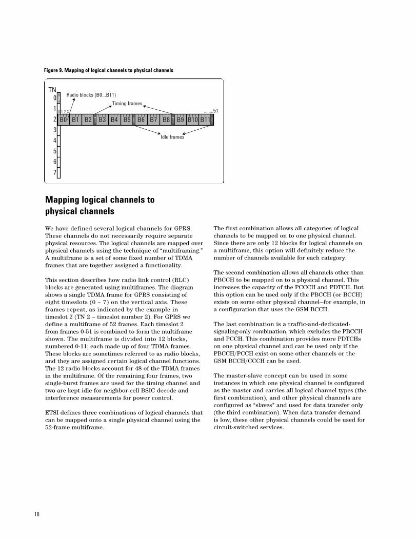
Mapping logical channels to physical channels
We have defined several logical channels for GPRS.These channels do not necessarily require separatephysical resources. The logical channels are mapped overphysical channels using the technique of “multiframing.”A multiframe is a set of some fixed number of TDMAframes that are together assigned a functionality.
This section describes how radio link control (RLC)blocks are generated using multiframes. The diagramshows a single TDMA frame for GPRS consisting of eight timeslots (0 – 7) on the vertical axis. These frames repeat, as indicated by the example in timeslot 2 (TN 2 – timeslot number 2). For GPRS wedefine a multiframe of 52 frames. Each timeslot 2 from frames 0-51 is combined to form the multiframeshown. The multiframe is divided into 12 blocks, numbered 0-11; each made up of four TDMA frames.These blocks are sometimes referred to as radio blocks,and they are assigned certain logical channel functions.The 12 radio blocks account for 48 of the TDMA framesin the multiframe. Of the remaining four frames, twosingle-burst frames are used for the timing channel andtwo are kept idle for neighbor-cell BSIC decode andinterference measurements for power control.
ETSI defines three combinations of logical channels thatcan be mapped onto a single physical channel using the52-frame multiframe.
The first combination allows all categories of logicalchannels to be mapped on to one physical channel.Since there are only 12 blocks for logical channels on a multiframe, this option will definitely reduce the number of channels available for each category.
The second combination allows all channels other thanPBCCH to be mapped on to a physical channel. Thisincreases the capacity of the PCCCH and PDTCH. Butthis option can be used only if the PBCCH (or BCCH)exists on some other physical channel—for example, in a configuration that uses the GSM BCCH.
The last combination is a traffic-and-dedicated-signaling-only combination, which excludes the PBCCHand PCCH. This combination provides more PDTCHs on one physical channel and can be used only if thePBCCH/PCCH exist on some other channels or the GSM BCCH/CCCH can be used.
The master-slave concept can be used in some instances in which one physical channel is configured as the master and carries all logical channel types (thefirst combination), and other physical channels are configured as “slaves” and used for data transfer only(the third combination). When data transfer demand is low, these other physical channels could be used forcircuit-switched services.
Figure 9. Mapping of logical channels to physical channels
B0 B1 B2 B3 B4 B5 B6 B7 B8 B9 B10 B11IT T I
........51
0
1
2
3
4
5
6
7
BCH
0 1 2 3
TNRadio blocks (B0…B11)
Timing frames
Idle frames
19
Coordination of GSM and GPRS functions
There are certain functions that are common to GSMand GPRS. These include paging, location updates, andattach/detach.
Paging is a critical function that must be coordinatedbetween GSM and GPRS. To do this, the network willoperate in one of three modes. This operation mode isbroadcast on the system information message and willbe the same within a routing area.
Network operation mode 1In this mode the mobile phone monitors only one paging channel during the GPRS attach. The network sends the circuit-switched paging either on a GPRS paging channel or on the GSM CCCH (common controlchannel) paging channel (depending on channel combinations). In order to send circuit-switched paging on the GPRS paging channel, the Gs interface must be present.
Network operation mode 2The CCCH paging channel is used for both circuit-switched and GPRS paging. Hence the mobile has to monitor only the CCCH paging channel.
Network operation mode 3In this mode the mobile monitors both the CCCH andthe GPRS paging channel (PPCH). The mobile will receive circuit-switched pages on the CCCH and GPRS pages on a PPCH. In order to monitor both paging channels, the mobile must be Class A or Class B.
Attach and location updates also depend on networkoperation modes and class of mobile. The network oper-ation mode is part of the broadcast system informationtransmitted to the mobiles, and it should be the samefor each cell within a routing area. Upon receiving thisinformation, the mobile determines whether to performa GRPS attach, an IMSI attach, or both. This determina-tion depends not only on the network mode, but also onthe class of mobile, which specifies whether or not themobile can perform simultaneous attach or detach.
In Network Operation Mode 1 with a mobile that is IMSI-and GPRS-attached, combined routing area/locationarea updates must be performed. In network operationmodes 2 or 3, a mobile that can be GPRS- and IMSI-attached must perform a routing area update and eitheraccess the circuit-switched control channel for circuit-switched operation or, if circuit-switched operation isnot required, perform a detach.
20
Multi-slot configurations
A multi-slot configuration consists of multiple circuit-orpacket-switched channels together with their associatedcontrol channels, all allocated to the same mobile phone.The multi-slot configuration occupies up to 8 physicalchannels, with different timeslot numbers (TNs) but thesame frequency parameters and the same trainingsequence.
A mobile may be allocated several PDTCH/Us (packettraffic data channel/uplink) or PDTCH/Ds (packet trafficdata channel/downlink) for a mobile-originated or amobile-terminated communication, respectively. In thiscontext, allocation refers to the list of PDCHs that candynamically carry the PDTCHs for that specific mobile.The PACCH may be mapped onto any of the allocatedPDCHs. If there are m timeslots allocated for receptionand n timeslots allocated for transmission, there shall be Min (m, n) reception and transmission timeslots with the same TN.
Multi-slot configuration depends on the type of mobiles:
• Type 1 mobiles do not transmit and receive simulta-neously. Hence their multi-slot usage is limited by the time required to do neighbor cell measurements.
• Type 2 mobiles can transmit and receive simultane-ously and hence support more slots.
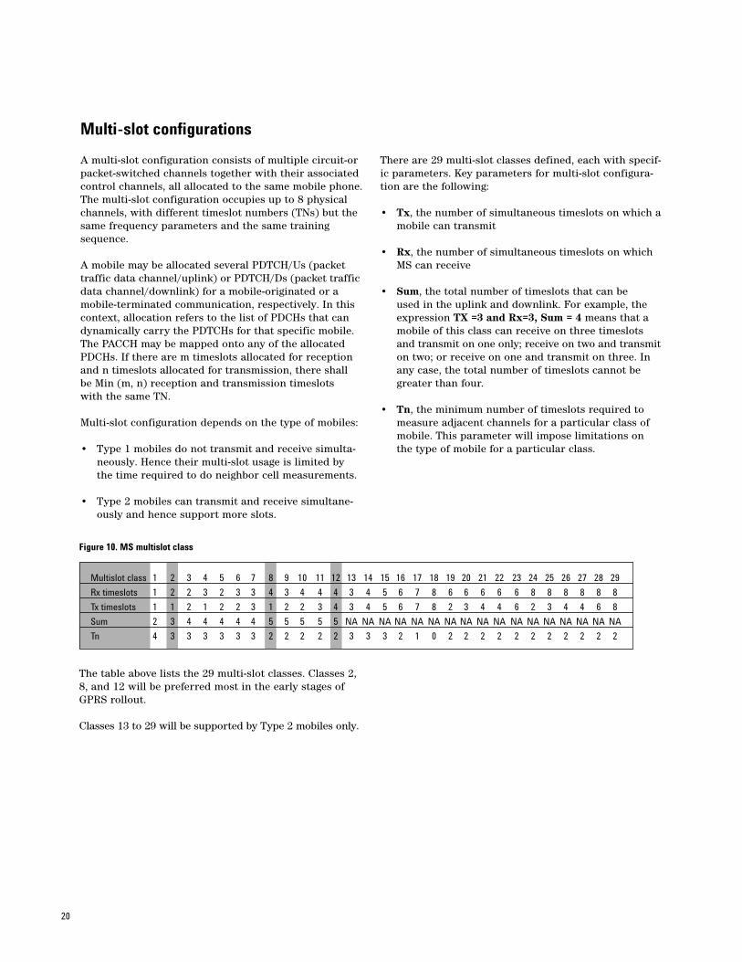
There are 29 multi-slot classes defined, each with specif-ic parameters. Key parameters for multi-slot configura-tion are the following:
• Tx, the number of simultaneous timeslots on which amobile can transmit
• Rx, the number of simultaneous timeslots on which MS can receive
• Sum, the total number of timeslots that can be used in the uplink and downlink. For example, the expression TX =3 and Rx=3, Sum = 4 means that a mobile of this class can receive on three timeslots and transmit on one only; receive on two and transmiton two; or receive on one and transmit on three. In any case, the total number of timeslots cannot be greater than four.
• Tn, the minimum number of timeslots required to measure adjacent channels for a particular class of mobile. This parameter will impose limitations on the type of mobile for a particular class.
Figure 10. MS multislot class
The table above lists the 29 multi-slot classes. Classes 2,8, and 12 will be preferred most in the early stages ofGPRS rollout.
Classes 13 to 29 will be supported by Type 2 mobiles only.
Multislot class 1 2 3 4 5 6 7 8 9 10 11 12 13 14 15 16 17 18 19 20 21 22 23 24 25 26 27 28 29
Rx timeslots 1 2 2 3 2 3 3 4 3 4 4 4 3 4 5 6 7 8 6 6 6 6 6 8 8 8 8 8 8
Tx timeslots 1 1 2 1 2 2 3 1 2 2 3 4 3 4 5 6 7 8 2 3 4 4 6 2 3 4 4 6 8
Sum 2 3 4 4 4 4 4 5 5 5 5 5 NA NA NA NA NA NA NA NA NA NA NA NA NA NA NA NA NA
Tn 4 3 3 3 3 3 3 2 2 2 2 2 3 3 3 2 1 0 2 2 2 2 2 2 2 2 2 2 2
21
RF power control
RF power control is used to minimize the transmitpower required by the mobile or BSS while still main-taining the quality of the radio links. By minimizing thetransmit power levels, interference among co-channelusers can be reduced.
For circuit-switched services, the mobile is commandedby the base station to change its power level. The basestation directs this process with the help of the uplinkRx level and Rx quality measurements. For GPRS, how-ever, the process is controlled by the mobile, since transmission is not continuous.
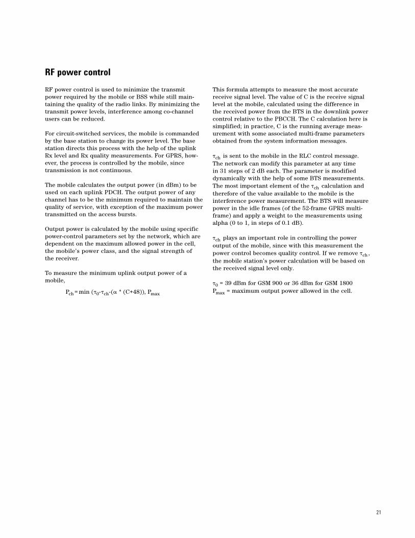
The mobile calculates the output power (in dBm) to beused on each uplink PDCH. The output power of anychannel has to be the minimum required to maintain thequality of service, with exception of the maximum powertransmitted on the access bursts.
Output power is calculated by the mobile using specificpower-control parameters set by the network, which aredependent on the maximum allowed power in the cell,the mobile’s power class, and the signal strength of the receiver.
To measure the minimum uplink output power of amobile,
This formula attempts to measure the most accuratereceive signal level. The value of C is the receive signallevel at the mobile, calculated using the difference in the received power from the BTS in the downlink powercontrol relative to the PBCCH. The C calculation here issimplified; in practice, C is the running average meas-urement with some associated multi-frame parametersobtained from the system information messages.
�ch is sent to the mobile in the RLC control message.The network can modify this parameter at any time in 31 steps of 2 dB each. The parameter is modifieddynamically with the help of some BTS measurements.The most important element of the �ch calculation andtherefore of the value available to the mobile is theinterference power measurement. The BTS will measurepower in the idle frames (of the 52-frame GPRS multi-frame) and apply a weight to the measurements usingalpha (0 to 1, in steps of 0.1 dB).
�ch plays an important role in controlling the power output of the mobile, since with this measurement thepower control becomes quality control. If we remove �ch ,the mobile station’s power calculation will be based onthe received signal level only.
�0 = 39 dBm for GSM 900 or 36 dBm for GSM 1800 Pmax = maximum output power allowed in the cell.Pch = min (�0-�ch-(� * (C+48)), Pmax
22
GPRS-mode timing advance
The main difference between circuit-switched transmissionand packet-switched transmission is that packet-switchedtransmission is not continuous. During circuit-switchedoperation, when the mobile is transmitting continuously,the BTS can easily derive the delay relative to previoustiming values. This would be very difficult in packet-switched applications, since the mobile will be transmittingon assigned radio blocks only and the interval betweentwo blocks could be significant. To avoid inter-timeslotinterference and other possible impairments, GPRSdeploys a new technique for achieving correct burst timing.
This technique, called timing advance, is carried out intwo parts:
• Initial timing advance is made, in a manner similar to circuit switching, whereby the initial delay is measured by the PRACH/RACH reception at the basestation using the extended guard period of 88 bits.
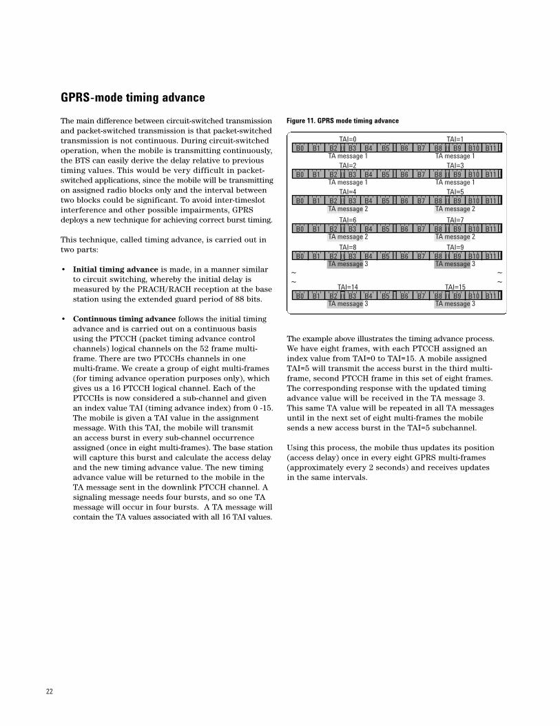
• Continuous timing advance follows the initial timing advance and is carried out on a continuous basis using the PTCCH (packet timing advance control channels) logical channels on the 52 frame multi-frame. There are two PTCCHs channels in one multi-frame. We create a group of eight multi-frames (for timing advance operation purposes only), which gives us a 16 PTCCH logical channel. Each of the PTCCHs is now considered a sub-channel and given an index value TAI (timing advance index) from 0 -15.The mobile is given a TAI value in the assignment message. With this TAI, the mobile will transmit an access burst in every sub-channel occurrence assigned (once in eight multi-frames). The base stationwill capture this burst and calculate the access delay and the new timing advance value. The new timing advance value will be returned to the mobile in the TA message sent in the downlink PTCCH channel. A signaling message needs four bursts, and so one TA message will occur in four bursts. A TA message willcontain the TA values associated with all 16 TAI values.
The example above illustrates the timing advance process.We have eight frames, with each PTCCH assigned anindex value from TAI=0 to TAI=15. A mobile assignedTAI=5 will transmit the access burst in the third multi-frame, second PTCCH frame in this set of eight frames.The corresponding response with the updated timingadvance value will be received in the TA message 3. This same TA value will be repeated in all TA messagesuntil in the next set of eight multi-frames the mobilesends a new access burst in the TAI=5 subchannel.
Using this process, the mobile thus updates its position(access delay) once in every eight GPRS multi-frames(approximately every 2 seconds) and receives updates in the same intervals.
Figure 11. GPRS mode timing advance
B0 B1 B2 B3 B4 B5 B6 B7 B8 B9 B10 B11IT T I
B0 B1 B2 B3 B4 B5 B6 B7 B8 B9 B10 B11IT T I
B0 B1 B2 B3 B4 B5 B6 B7 B8 B9 B10 B11IT T I
B0 B1 B2 B3 B4 B5 B6 B7 B8 B9 B10 B11IT T I
B0 B1 B2 B3 B4 B5 B6 B7 B8 B9 B10 B11IT T I
B0 B1 B2 B3 B4 B5 B6 B7 B8 B9 B10 B11IT T I
TAI=0 TAI=1
TAI=2 TAI=3
TAI=4 TAI=5
TAI=6 TAI=7
TAI=8 TAI=9
TAI=14 TAI=15
TA message 1 TA message 1
TA message 1 TA message 1
TA message 2 TA message 2
TA message 2 TA message 2
TA message 3 TA message 3
TA message 3 TA message 3
~~
~~
23
Coding data on radio blocks
Having defined some common RF processes and operations,we turn again to the information being sent on the airinterface. Earlier we discussed briefly the coding on theradio interface. The radio interface limits the maximumdata transfer rate. One TDMA burst can carry up to 114bits of information; therefore, each radio block of fourbursts can carry only 456 bits of information. The infor-mation carried in those bits is the user data and coding.Coding provides error detection and error correction,and it is essential for managing the impairments on theair interface.
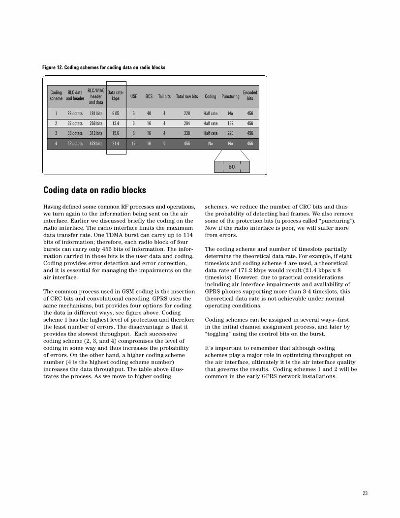
The common process used in GSM coding is the insertionof CRC bits and convolutional encoding. GPRS uses thesame mechanisms, but provides four options for codingthe data in different ways, see figure above. Codingscheme 1 has the highest level of protection and thereforethe least number of errors. The disadvantage is that itprovides the slowest throughput. Each successive coding scheme (2, 3, and 4) compromises the level of coding in some way and thus increases the probabilityof errors. On the other hand, a higher coding schemenumber (4 is the highest coding scheme number)increases the data throughput. The table above illus-trates the process. As we move to higher coding
schemes, we reduce the number of CRC bits and thusthe probability of detecting bad frames. We also removesome of the protection bits (a process called “puncturing”).Now if the radio interface is poor, we will suffer morefrom errors.
The coding scheme and number of timeslots partiallydetermine the theoretical data rate. For example, if eighttimeslots and coding scheme 4 are used, a theoreticaldata rate of 171.2 kbps would result (21.4 kbps x 8timeslots). However, due to practical considerationsincluding air interface impairments and availability ofGPRS phones supporting more than 3-4 timeslots, thistheoretical data rate is not achievable under normaloperating conditions.
Coding schemes can be assigned in several ways—first in the initial channel assignment process, and later by“toggling” using the control bits on the burst.
It’s important to remember that although codingschemes play a major role in optimizing throughput onthe air interface, ultimately it is the air interface qualitythat governs the results. Coding schemes 1 and 2 will becommon in the early GPRS network installations.
Figure 12. Coding schemes for coding data on radio blocks
Coding RLC data RLC/MAC Data rate- Encodedscheme and header header kbps USF BCS Tail bits Total raw bits Coding Puncturing bits
and data
1 22 octets 181 bits 9.05 3 40 4 228 Half rate No 456
2 32 octets 268 bits 13.4 6 16 4 294 Half rate 132 456
3 38 octets 312 bits 15.6 6 16 4 338 Half rate 220 456
4 52 octets 428 bits 21.4 12 16 0 456 No No 456
BO
24
In this final section we examine some of the proceduresassociated with packet data transfer. This is importantbecause the concepts described here will provide valu-able background information for RF engineers who arerequired to troubleshoot GPRS data network problemsusing the layer 3 message protocol decoding capabilityof commercial drive test tools from vendors such asAgilent Technologies.
As we have already seen, to initiate a packet transfer a GPRS mobile first must attach itself to the GPRS net-work, and then perform a GPRS-specific process knownas PDP context activation. The PDP context assigns anIP address to the mobile (if it has no static address).Then the mobile can access the network, requestresources, send data, go into standby mode if no data isbeing transmitted, and repeat the process over again.
Uplink packet data transfer
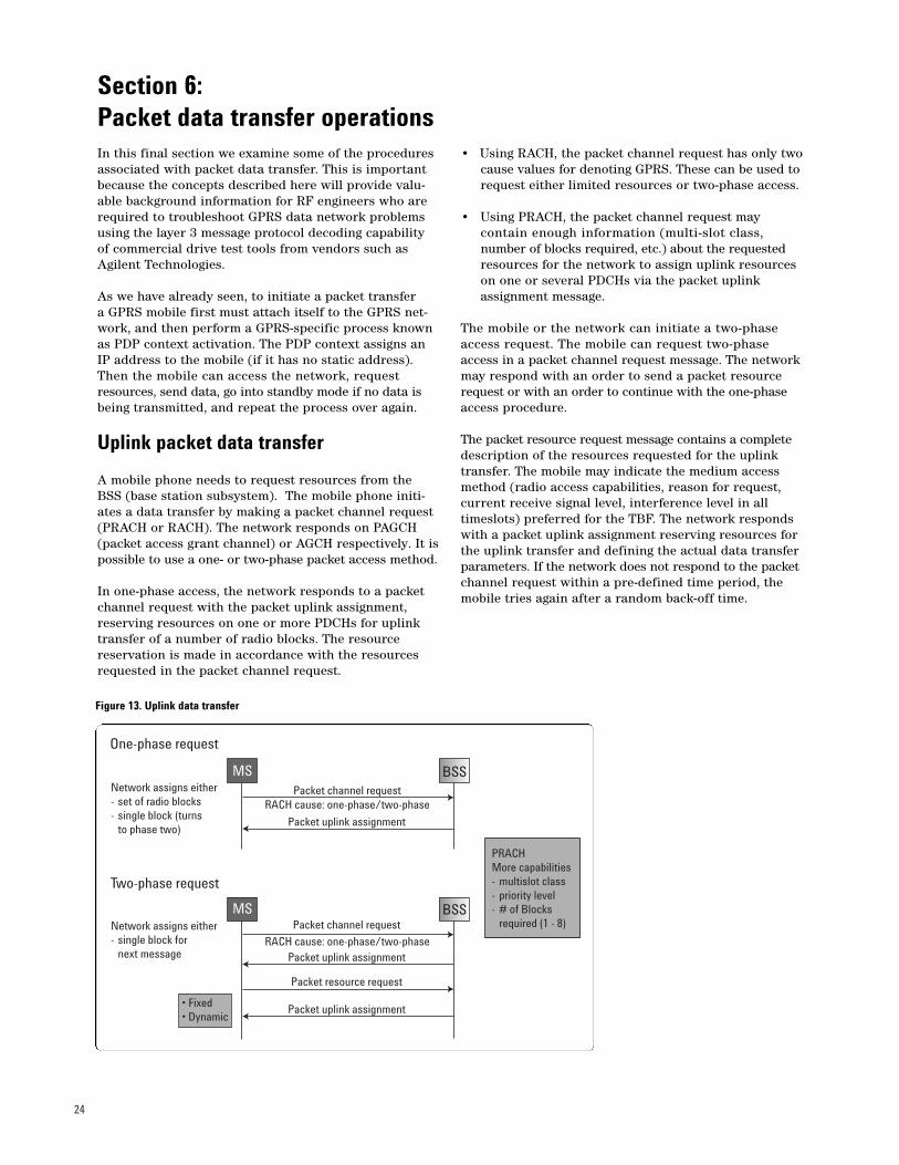
A mobile phone needs to request resources from theBSS (base station subsystem). The mobile phone initi-ates a data transfer by making a packet channel request(PRACH or RACH). The network responds on PAGCH(packet access grant channel) or AGCH respectively. It ispossible to use a one- or two-phase packet access method.
In one-phase access, the network responds to a packetchannel request with the packet uplink assignment,reserving resources on one or more PDCHs for uplink transfer of a number of radio blocks. The resource reservation is made in accordance with the resourcesrequested in the packet channel request.
• Using RACH, the packet channel request has only twocause values for denoting GPRS. These can be used torequest either limited resources or two-phase access.
• Using PRACH, the packet channel request may contain enough information (multi-slot class,number of blocks required, etc.) about the requested resources for the network to assign uplink resources on one or several PDCHs via the packet uplink assignment message.
The mobile or the network can initiate a two-phaseaccess request. The mobile can request two-phase access in a packet channel request message. The networkmay respond with an order to send a packet resourcerequest or with an order to continue with the one-phaseaccess procedure.
The packet resource request message contains a completedescription of the resources requested for the uplinktransfer. The mobile may indicate the medium accessmethod (radio access capabilities, reason for request,current receive signal level, interference level in alltimeslots) preferred for the TBF. The network respondswith a packet uplink assignment reserving resources forthe uplink transfer and defining the actual data transferparameters. If the network does not respond to the packetchannel request within a pre-defined time period, themobile tries again after a random back-off time.
Figure 13. Uplink data transfer
Section 6: Packet data transfer operations
Network assigns either- set of radio blocks- single block (turns
to phase two)
Network assigns either- single block for
next message
One-phase request
Two-phase request
PRACHMore capabilities- multislot class- priority level- # of Blocks
required (1 - 8)
• Fixed• Dynamic
MS BSS
MS BSS
Packet channel requestRACH cause: one-phase/two-phase
RACH cause: one-phase/two-phase
Packet channel request
Packet uplink assignment
Packet uplink assignment
Packet resource request
Packet uplink assignment
25
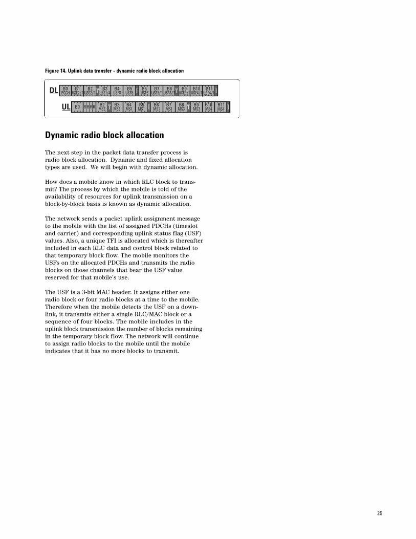
Dynamic radio block allocation
The next step in the packet data transfer process isradio block allocation. Dynamic and fixed allocationtypes are used. We will begin with dynamic allocation.
How does a mobile know in which RLC block to trans-mit? The process by which the mobile is told of theavailability of resources for uplink transmission on ablock-by-block basis is known as dynamic allocation.
The network sends a packet uplink assignment messageto the mobile with the list of assigned PDCHs (timeslotand carrier) and corresponding uplink status flag (USF)values. Also, a unique TFI is allocated which is thereafterincluded in each RLC data and control block related tothat temporary block flow. The mobile monitors theUSFs on the allocated PDCHs and transmits the radioblocks on those channels that bear the USF valuereserved for that mobile’s use.
The USF is a 3-bit MAC header. It assigns either oneradio block or four radio blocks at a time to the mobile.Therefore when the mobile detects the USF on a down-link, it transmits either a single RLC/MAC block or asequence of four blocks. The mobile includes in theuplink block transmission the number of blocks remainingin the temporary block flow. The network will continueto assign radio blocks to the mobile until the mobileindicates that it has no more blocks to transmit.
Figure 14. Uplink data transfer - dynamic radio block allocation
B0 B1 B2 B3 B4 B5 B6 B7 B8 B9 B10 B11IT T IPCCH USF2/1 USF2/1 USF1/4 USF8 USF8 USF8 USF3/1 USF3/1 USF3/1 USF4/1 USF4/1
B0 B2 B3 B4 B5 B6 B7 B8 B9 B10 B11IT T IMS2 MS2 MS1 MS1 MS1 MS1 MS3 MS3 MS4 MS4
DL
UL R R R R
26
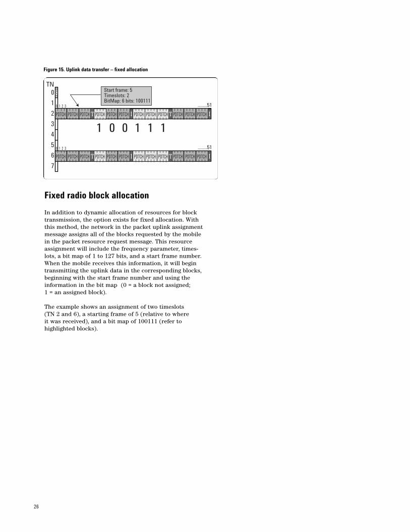
Fixed radio block allocation
In addition to dynamic allocation of resources for blocktransmission, the option exists for fixed allocation. Withthis method, the network in the packet uplink assignmentmessage assigns all of the blocks requested by the mobilein the packet resource request message. This resourceassignment will include the frequency parameter, times-lots, a bit map of 1 to 127 bits, and a start frame number.When the mobile receives this information, it will begintransmitting the uplink data in the corresponding blocks,beginning with the start frame number and using theinformation in the bit map (0 = a block not assigned; 1 = an assigned block).
The example shows an assignment of two timeslots (TN 2 and 6), a starting frame of 5 (relative to where it was received), and a bit map of 100111 (refer to highlighted blocks).
Figure 15. Uplink data transfer – fixed allocation
PDTCH PDTCH PDTCH PDTCH PDTCH PDTCH PDTCH PDTCH PDTCH PDTCH PDTCHIT T I........51
0
1
2
3
4
5
6
7
BCH
0 1 2 3
PDTCH PDTCH PDTCH PDTCH PDTCH PDTCH PDTCH PDTCH PDTCH PDTCH PDTCH PDTCHIT T I........510 1 2 3
TNStart frame: 5Timeslots: 2BitMap: 6 bits: 100111
PDTCH PDTCH PDTCH PDTCHPDTCH PDTCH
PDTCH PDTCH PDTCH PDTCH
1 0 0 1 1 1
27
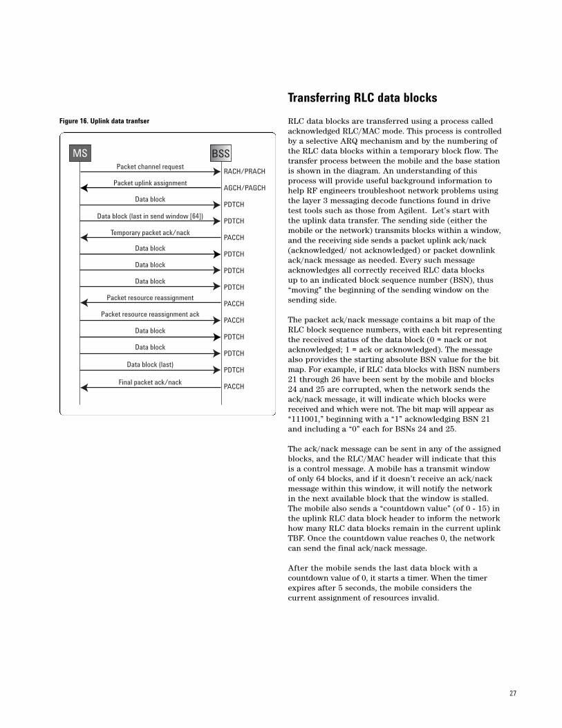
Transferring RLC data blocks
RLC data blocks are transferred using a process calledacknowledged RLC/MAC mode. This process is controlledby a selective ARQ mechanism and by the numbering ofthe RLC data blocks within a temporary block flow. Thetransfer process between the mobile and the base stationis shown in the diagram. An understanding of thisprocess will provide useful background information tohelp RF engineers troubleshoot network problems usingthe layer 3 messaging decode functions found in drivetest tools such as those from Agilent. Let’s start withthe uplink data transfer. The sending side (either themobile or the network) transmits blocks within a window,and the receiving side sends a packet uplink ack/nack(acknowledged/ not acknowledged) or packet downlinkack/nack message as needed. Every such messageacknowledges all correctly received RLC data blocks up to an indicated block sequence number (BSN), thus“moving” the beginning of the sending window on thesending side.
The packet ack/nack message contains a bit map of theRLC block sequence numbers, with each bit representingthe received status of the data block (0 = nack or notacknowledged; 1 = ack or acknowledged). The messagealso provides the starting absolute BSN value for the bitmap. For example, if RLC data blocks with BSN numbers21 through 26 have been sent by the mobile and blocks24 and 25 are corrupted, when the network sends theack/nack message, it will indicate which blocks werereceived and which were not. The bit map will appear as“111001,” beginning with a “1” acknowledging BSN 21and including a “0” each for BSNs 24 and 25.
The ack/nack message can be sent in any of the assignedblocks, and the RLC/MAC header will indicate that thisis a control message. A mobile has a transmit window of only 64 blocks, and if it doesn’t receive an ack/nackmessage within this window, it will notify the networkin the next available block that the window is stalled.The mobile also sends a “countdown value” (of 0 - 15) inthe uplink RLC data block header to inform the networkhow many RLC data blocks remain in the current uplinkTBF. Once the countdown value reaches 0, the networkcan send the final ack/nack message.
After the mobile sends the last data block with a countdown value of 0, it starts a timer. When the timerexpires after 5 seconds, the mobile considers the current assignment of resources invalid.
Figure 16. Uplink data tranfser
MS BSSPacket channel request
Packet uplink assignment
Data block
Data block
Data block
Data block
Data block
Data block
Packet resource reassignment
Final packet ack/nack
Packet resource reassignment ack
Data block (last in send window [64])
Data block (last)
Temporary packet ack/nack
RACH/PRACH
AGCH/PAGCH
PDTCH
PDTCH
PACCH
PDTCH
PDTCH
PDTCH
PACCH
PACCH
PDTCH
PDTCH
PDTCH
PACCH
28
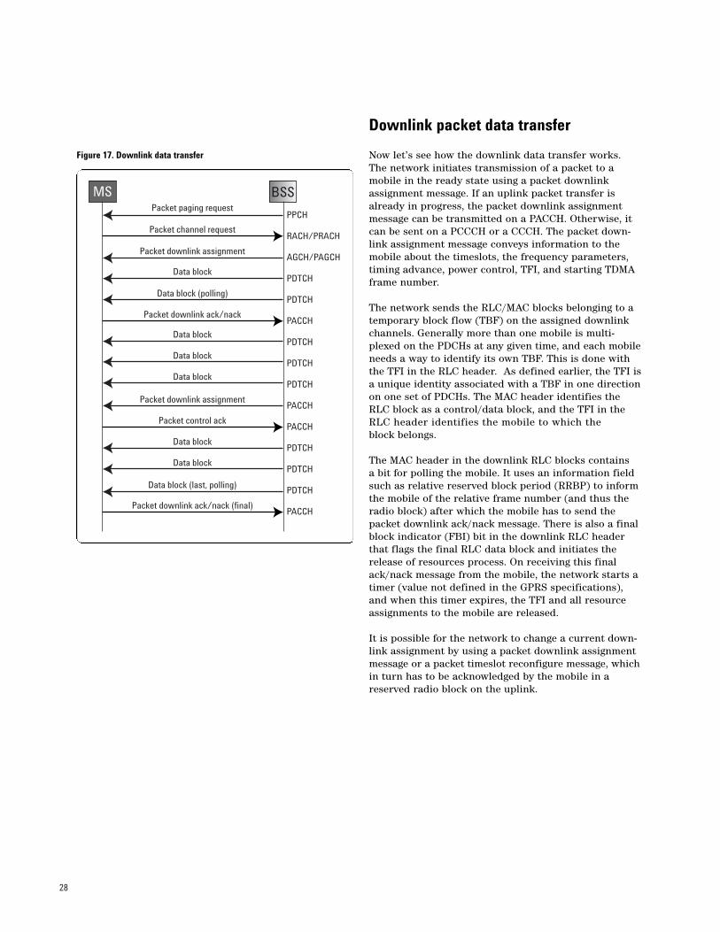
Downlink packet data transfer
Now let’s see how the downlink data transfer works.The network initiates transmission of a packet to amobile in the ready state using a packet downlinkassignment message. If an uplink packet transfer isalready in progress, the packet downlink assignmentmessage can be transmitted on a PACCH. Otherwise, itcan be sent on a PCCCH or a CCCH. The packet down-link assignment message conveys information to themobile about the timeslots, the frequency parameters,timing advance, power control, TFI, and starting TDMAframe number.
The network sends the RLC/MAC blocks belonging to atemporary block flow (TBF) on the assigned downlinkchannels. Generally more than one mobile is multi-plexed on the PDCHs at any given time, and each mobileneeds a way to identify its own TBF. This is done withthe TFI in the RLC header. As defined earlier, the TFI isa unique identity associated with a TBF in one directionon one set of PDCHs. The MAC header identifies theRLC block as a control/data block, and the TFI in theRLC header identifies the mobile to which the block belongs.
The MAC header in the downlink RLC blocks contains a bit for polling the mobile. It uses an information fieldsuch as relative reserved block period (RRBP) to informthe mobile of the relative frame number (and thus theradio block) after which the mobile has to send thepacket downlink ack/nack message. There is also a finalblock indicator (FBI) bit in the downlink RLC headerthat flags the final RLC data block and initiates therelease of resources process. On receiving this finalack/nack message from the mobile, the network starts atimer (value not defined in the GPRS specifications),and when this timer expires, the TFI and all resourceassignments to the mobile are released.
It is possible for the network to change a current down-link assignment by using a packet downlink assignmentmessage or a packet timeslot reconfigure message, whichin turn has to be acknowledged by the mobile in areserved radio block on the uplink.
Figure 17. Downlink data transfer
MS BSSPacket paging request
Packet channel request
Packet downlink assignment
Data block
Data block
Data block
Data block
Data block
Data block
Packet downlink assignment
Packet downlink ack/nack (final)
Packet control ack
Data block (polling)
Data block (last, polling)
Packet downlink ack/nack
PPCH
RACH/PRACH
AGCH/PAGCH
PDTCH
PDTCH
PACCH
PDTCH
PDTCH
PDTCH
PACCH
PACCH
PDTCH
PDTCH
PDTCH
PACCH
29
Cell reselection
The final data transfer process that we will consider is cell reselection. This is useful for understanding howa mobile will hand over a call from cell to cell as themobile moves through the wireless network.
In GSM, cell reselection is an idle-mode procedure in which no dedicated resources are assigned to themobile. Instead the process is accomplished by C1 andC2 calculations.
In GPRS, cell reselection is done in packet transfer mode as well as in idle mode. GPRS also uses the C1 calculation, which is called the path loss criterion, andsettable parameters such as the receive level minimum,access power, and classmark. These parameters usedto calculate C1 are now GPRS-specific.
Optionally GPRS systems can use the C31 calculation,known as the signal level criterion. This calculation provides additional fixed and temporary offsets to C1 for hierarchical cell structures and it is used to prioritize cells for GPRS reselection. That is, if all cellsin a network are not GPRS cells, it is preferable to forcethe GPRS mobiles to attach to a GPRS cell. The C31 calculations enable the process.
In order to further differentiate cells that have the samepriority, GPRS can use the C32 calculations known asthe cell ranking criterion parameter.
The network may control its cell-reselection and requestmeasurement reports from the mobile. The request isindicated by the parameter network_control_order,which has three possible values defined as the following:
• NC0, which is the normal mobile station control mode. In this mode the mobile performs autonomouscell reselection using C1, C31, and C32.
• NC1, which is a mobile station control mode with measurement reports. In this mode the mobile sends measurement reports to the network and performs autonomous cell reselection using C1, C31, and C32.
• NC2, which is a network control mode. In this mode, the mobile sends measurement reports to the networkbut does not perform autonomous reselection. Instead the GPRS network does the packet resource reassignments.
Summary
GPRS technology adds packet-switching capability to GSMthat opens the door for new Internet-based services andother high-speed data applications. However, GPRS alsoadds new protocols and complexity to the network. Anunderstanding of the technology and the changes itbrings will be vital for successful deployment of GPRSand a full realization of the benefits it brings to themobile network.

30

31
Agilent Technologies’ Test andMeasurement Support, Services, and AssistanceAgilent Technologies aims to maximize thevalue you receive, while minimizing yourrisk and problems. We strive to ensurethat you get the test and measurementcapabilities you paid for and obtain thesupport you need. Our extensive supportresources and services can help youchoose the right Agilent products for yourapplications and apply them successfully.Every instrument and system we sell has aglobal warranty. Support is available for atleast five years beyond the production lifeof the product. Two concepts underlieAgilent's overall support policy: “OurPromise” and “Your Advantage.”
Our PromiseOur Promise means your Agilent test andmeasurement equipment will meet itsadvertised performance and functionality.When you are choosing new equipment,we will help you with product information,including realistic performance specifica-tions and practical recommendations fromexperienced test engineers. When you useAgilent equipment, we can verify that itworks properly, help with product operation,and provide basic measurement assistancefor the use of specified capabilities, at noextra cost upon request. Many self-helptools are available.
Your AdvantageYour Advantage means that Agilent offers a wide range of additional experttest and measurement services, whichyou can purchase according to yourunique technical and business needs.Solve problems efficiently and gain a competitive edge by contracting with usfor calibration, extra-cost upgrades, out-of-warranty repairs, and on-site educationand training, as well as design, systemintegration, project management, andother professional engineering services.Experienced Agilent engineers and techni-cians worldwide can help you maximizeyour productivity, optimize the return oninvestment of your Agilent instrumentsand systems, and obtain dependablemeasurement accuracy for the life ofthose products.
By internet, phone, or fax, get assistancewith all your test and measurement needs
Online assistance:www.agilent.com/find/assist
Phone or FaxUnited States:(tel) 1 800 452 4844
Canada:(tel) 1 877 894 4414(fax) (905) 282-6495
China:(tel) 800-810-0189(fax) 1-0800-650-0121
Europe:(tel) (31 20) 547 2323(fax) (31 20) 547 2390
Japan:(tel) (81) 426 56 7832(fax) (81) 426 56 7840
Korea:(tel) (82-2) 2004-5004 (fax) (82-2) 2004-5115
Latin America:(tel) (305) 269 7500(fax) (305) 269 7599
Taiwan:(tel) 080-004-7866 (fax) (886-2) 2545-6723
Other Asia Pacific Countries:(tel) (65) 375-8100 (fax) (65) 836-0252Email: [email protected]
Product specifications and descriptions in this document subject to change without notice.
© Agilent Technologies, Inc. 2001Printed in USA June 28, 20015988-2598EN