Embed Size (px)
Citation preview
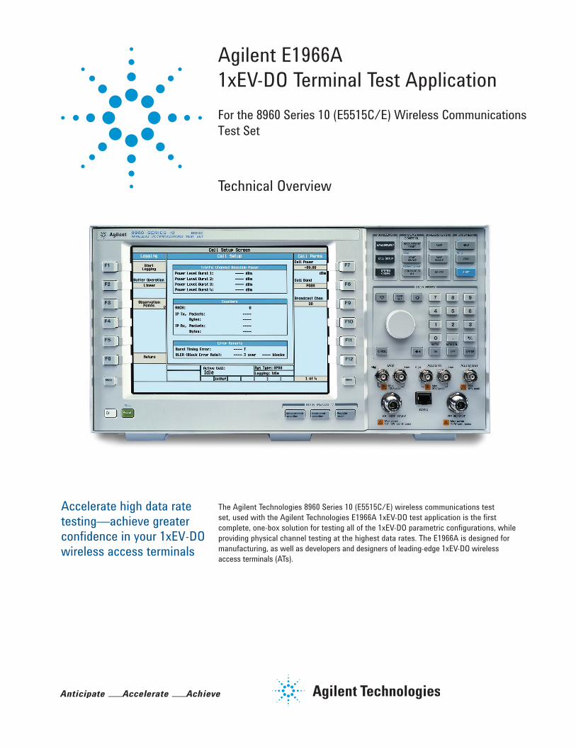
Agilent E1966A 1xEV-DO Terminal Test Application
Accelerate high data rate testing—achieve greater confidence in your 1xEV-DO wireless access terminals
For the 8960 Series 10 (E5515C/E) Wireless Communications Test Set
The Agilent Technologies 8960 Series 10 (E5515C/E) wireless communications test set, used with the Agilent Technologies E1966A 1xEV-DO test application is the first complete, one-box solution for testing all of the 1xEV-DO parametric configurations, while providing physical channel testing at the highest data rates. The E1966A is designed for manufacturing, as well as developers and designers of leading-edge 1xEV-DO wireless access terminals (ATs).
Technical Overview
2
Key Features • Supports 1xEV-DO Release 0 FTAP/RTAP, and optionally 1xEV-DO Release A FETAP/RETAP (Option 102) and Release B FMCTAP/RMCTAP (Option 103) call processing for accurate physical layer performance qualification
• Supports new forward link packet configurations (Option 104) including those using 64QAM that boost the potential data throughput from 3.1 up to 4.9 Mbps with one box or from 9.3 to 14.7 Mbps with three boxes over FMCTAP/RMCTAP
• Supports Release B multi-carrier physical layer test with one box in IS-856 test mode • Reduces the risk of returns and recalls by testing packet error rate at all QPSK, 8PSK, 16QAM, and 64QAM forward link modulation modes supported in the 1xEV-DO Release 0, Release A, and Release B standards. Verifies new reverse link modulation formats including 8PSK supported in the 1xEV-DO Release A standard (Option 102)
• Supports all commercialized bands—0 (including Band subclass 4 for China Telecom), 1, 3, 4, 5, 6, 7, 10, 11, 12, 14, 15, 18, and 19
• Single channel GPS source simulates one satellite for calibration of UE’s built-in GPS receiver (Option E1999A-206)
• IS-856 test mode allows receiver testing without call processing
• E1987A fast switch test application enables rapid switching between the E1966A 1xEV-DO test application and the E1962B cdma2000® test application for dual mode phone test • Options 405, 406, and 407 offer fading, multi-unit synchronization, and protocol logging features for mobile design and verification
3
E1966A Functionality Overview
Flexible network emulation for physical layer test The E1966A 1xEV-DO test application supports flexible call processing for physical layer testing of 1xEV-DO ATs. Establishing sessions with the test set is completely automatic once the test set is configured with the correct frequency band, channel, and sector ID. The test set automatically handles random ATI requests from access terminals, UATI assignment, and session negotiation. Once a session is established, test connections are initiated by a single connect command. When connected, powerful active, closed-loop power control can be used to manipulate the ATs as required for testing. Tests across multiple channels and frequency bands are fast and simple using the one-button handoff commands.
Standardized, call processing-based test mode connections The E1966A supports physical layer testing through the standardized FTAP/RTAP over-the-air protocols (forward and reverse test application protocols). FTAP allows accurate receiver packet error rate measurements by eliminating the dynamic behaviors of the 1xEV-DO system. RTAP provides control of the ATs’ reverse link enabling accurate reverse link measurements. RTAP allows such measurements as channel power, waveform quality, code domain power, and Tx spurious emissions.
Option 102 – 1xEV-DO Release A and B test support The E1966A Option 102 supports testing of the 1xEV-DO Release A physical layer subtype 2 air interface using the enhanced test application protocol. Call processing with this new air interface is simple and easy using one-button commands—just like it is with the existing Release 0 functionality. Option 102 adds support for all of the new forward traffic channel configurations and enables accurate PER testing under realistic condi-tions using the new FETAP protocol (forward enhanced test application protocol). Using the new RETAP protocol (reverse enhanced test application protocol), all of the new subtype 2 reverse channel packet sizes and modulation types are easily tested for such parameters as power, waveform quality, code domain power, and Tx spurious emissions. The option also supports testing of the new 1xEV-DO Release B physical layer subtype 3 air interface using the multi-carrier test application protocol on signal carrier.
Option 103 – 1xEV-DO multi-carrier test support The E1966A Option 103 supports testing of the 1xEV-DO Release B physical subtype 3 air interface that includes multiple carriers using the new multi-carrier test application protocol. Up to three test sets can be interconnected via LAN and clock signals, to generate and analyze devices that support multi-carrier operation. Call processing with this air interface is simple and easy using one button commands from the test set designated as the multi-carrier master unit—the same as it is with the existing Release 0/A functionality. The multi-carrier master controls all main call processing functions and coordinates con-trol with up to two other E5515C/E units designated as auxiliary units. As test standards define all multi-carrier tests to be performed on a per carrier basis, each test set makes independent measurements on each carrier. Option 103 supports all defined FMCTAP and RMCTAP multi-carrier test cases for: waveform quality and frequency accuracy, maximum RF output power, conducted spurious emissions, forward traffic channel performance in AWGN, sensitivity and dynamic range and with an external signal generator, and single tone desensitization.
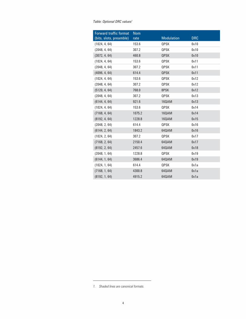
Option 104 – 1xEV-DO optional DRC support The E1966A Option 104 supports testing of the 1xEV-DO Release B physical subtype 3 air interface that includes the optional subtype 3 DRC values (including those forward traffic formats that use 64QAM). Up to 4.9 Mbps physical layer tests can be made with one test set, or 14.7 Mbps with three test sets, via FMCTAP and RMCTAP. The option also supports demodulation testing of these DRC values using FMCTAP.
4
Table: Optional DRC values1
Forward traffic format (bits, slots, preamble)
Nomrate Modulation DRC
(1024, 4, 64) 153.6 QPSK 0x10 (2048, 4, 64) 307.2 QPSK 0x10 (3072, 4, 64) 460.8 QPSK 0x10 (1024, 4, 64) 153.6 QPSK 0x11 (2048, 4, 64) 307.2 QPSK 0x11 (4096, 4, 64) 614.4 QPSK 0x11 (1024, 4, 64) 153.6 QPSK 0x12 (2048, 4, 64) 307.2 QPSK 0x12 (5120, 4, 64) 768.0 8PSK 0x12 (2048, 4, 64) 307.2 QPSK 0x13 (6144, 4, 64) 921.6 16QAM 0x13 (1024, 4, 64) 153.6 QPSK 0x14 (7168, 4, 64) 1075.2 16QAM 0x14 (8192, 4, 64) 1228.8 16QAM 0x15 (2048, 2, 64) 614.4 QPSK 0x16 (6144, 2, 64) 1843.2 64QAM 0x16 (1024, 2, 64) 307.2 QPSK 0x17 (7168, 2, 64) 2150.4 64QAM 0x17 (8192, 2, 64) 2457.6 64QAM 0x18 (2048, 1, 64) 1228.8 QPSK 0x19 (6144, 1, 64) 3686.4 64QAM 0x19 (1024, 1, 64) 614.4 QPSK 0x1a (7168, 1, 64) 4300.8 64QAM 0x1a (8192, 1, 64) 4915.2 64QAM 0x1a
1. Shaded lines are canonical formats.
5
E1966A Functionality Overview (Continued)
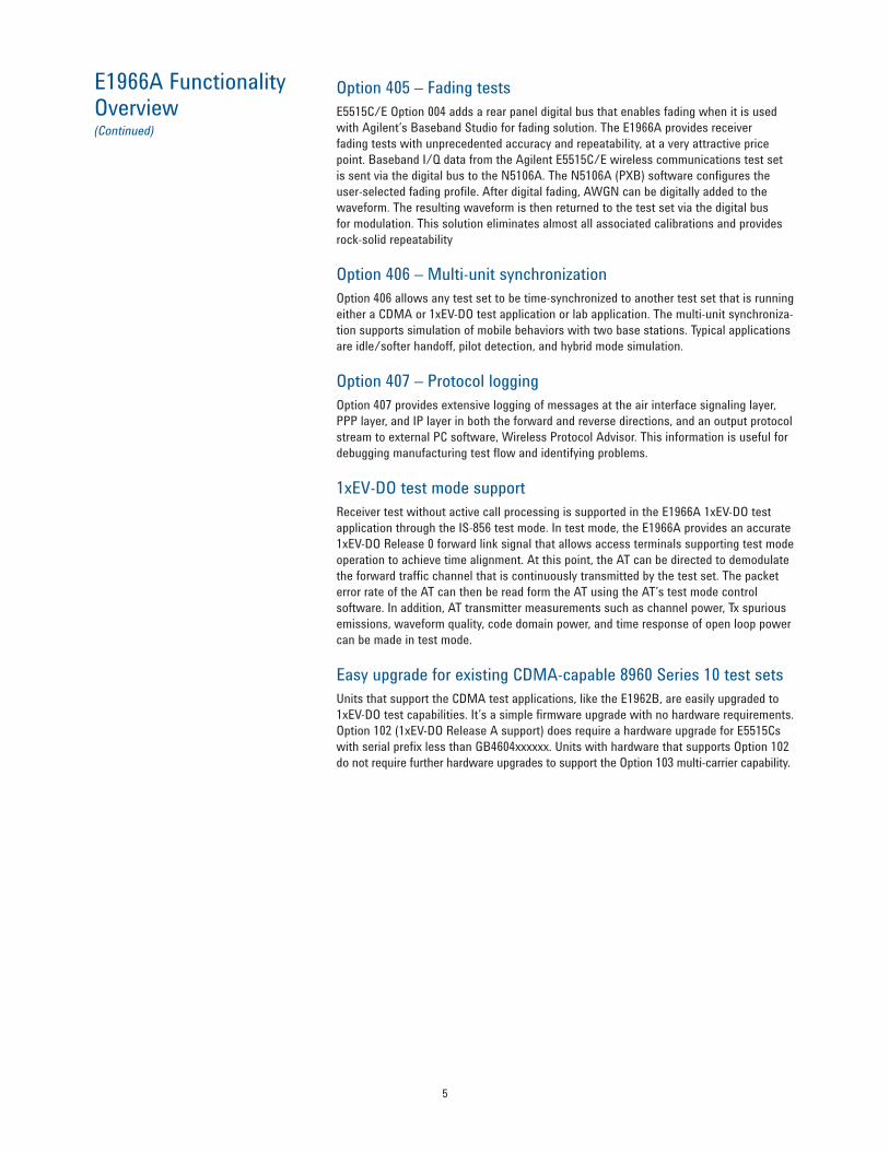
Option 405 – Fading tests E5515C/E Option 004 adds a rear panel digital bus that enables fading when it is used with Agilent’s Baseband Studio for fading solution. The E1966A provides receiver fading tests with unprecedented accuracy and repeatability, at a very attractive price point. Baseband I/Q data from the Agilent E5515C/E wireless communications test set is sent via the digital bus to the N5106A. The N5106A (PXB) software configures the user-selected fading profile. After digital fading, AWGN can be digitally added to the waveform. The resulting waveform is then returned to the test set via the digital bus for modulation. This solution eliminates almost all associated calibrations and provides rock-solid repeatability
Option 406 – Multi-unit synchronization Option 406 allows any test set to be time-synchronized to another test set that is running either a CDMA or 1xEV-DO test application or lab application. The multi-unit synchroniza-tion supports simulation of mobile behaviors with two base stations. Typical applications are idle/softer handoff, pilot detection, and hybrid mode simulation.
Option 407 – Protocol logging Option 407 provides extensive logging of messages at the air interface signaling layer, PPP layer, and IP layer in both the forward and reverse directions, and an output protocol stream to external PC software, Wireless Protocol Advisor. This information is useful for debugging manufacturing test flow and identifying problems.
1xEV-DO test mode support Receiver test without active call processing is supported in the E1966A 1xEV-DO test application through the IS-856 test mode. In test mode, the E1966A provides an accurate 1xEV-DO Release 0 forward link signal that allows access terminals supporting test mode operation to achieve time alignment. At this point, the AT can be directed to demodulate the forward traffic channel that is continuously transmitted by the test set. The packet error rate of the AT can then be read form the AT using the AT’s test mode control software. In addition, AT transmitter measurements such as channel power, Tx spurious emissions, waveform quality, code domain power, and time response of open loop power can be made in test mode.
Easy upgrade for existing CDMA-capable 8960 Series 10 test sets Units that support the CDMA test applications, like the E1962B, are easily upgraded to 1xEV-DO test capabilities. It’s a simple firmware upgrade with no hardware requirements. Option 102 (1xEV-DO Release A support) does require a hardware upgrade for E5515Cs with serial prefix less than GB4604xxxxxx. Units with hardware that supports Option 102 do not require further hardware upgrades to support the Option 103 multi-carrier capability.

6
E1966A Functionality Overview (Continued)
Technical Specifications These specifications apply to all E5515Es, or E5515C mainframe with Option 003, and an E1966A test application of firmware revision A.09.13 or higher.
Specifications describe the test set’s warranted performance and are valid over the entire operation and environmental ranges unless otherwise noted. All specifications are valid after a 30-minute warm-up period of continuous operation.
Supplemental characteristics are intended to provide additional information useful in applying the instrument by giving typical, but non-warranted performance parameters. These characteristics are shown in italics and labeled as typical, or supplemental. All units shipped from the factory meet these typical numbers at 25 °C ambient without including measurement uncertainty.
1xEV-DO call processing • UATI assign • Session negotiation • FTAP and RTAP support • FMCTAP and RMCTAP support (optional)
Tx measurements • Average power • Code domain power • Modulation quality • Spectrum monitor • Tx dynamic power
Rx measurements • FTAP/FETAP/FMCTAP loopback • Dynamic range • Data rate control performance
• Session open • Connect/disconnect • FETAP and RETAP support (optional) • Release B optional DRC (optional)
• Channel power • Access probe power • Time response of open loop power • Tx spurious emissions • Fast device tune (optional)
• Sensitivity • PER with AWGN

7
Analog Specifications CW RF generatorFrequencyAvailable frequency range 292 to 2700 MHzSpecified frequency ranges 421 to 494 MHz, 800 to 960 MHz, and 1700 to 2000 MHzAccuracy and stability Same as timebase referenceTest signal CW, AM (56% depth with 20 kHz rate), or DSB-SC (carrier + upper side-band spaced 20 kHz apart). Requires approximately 3 seconds to switch between test signal selections
AmplitudeAvailable output level range −127 to −10 dBmSpecified output level range −116 to −15 dBmAbsolute output level accuracy < ±1.0 dB, typically < ±0.5 dB (Level accuracy at RF generator output levels > −30 dBm may be degraded by simultaneous reception and transmission when applied Tx power is > 32 dBm)VSWR at RF IN/OUT < 1.14:1, 400 to 1000 MHzNominal ambient test signal < ±1.1 dBlevel accuracy
Spectrum monitorInput frequency ranges 411 to 420 MHz 450 to 484 MHz 821 to 934 MHz 1700 to 1980 MHzReference level Auto or manualManual reference level range +37 to −50 dBmDisplay dB per division 20.0 to 0.1 dB per divisionLevel measurement accuracy Typically < ±1.0 dB 15 to 55 °C (Calibrated against average power and within ±10 degrees of calibration temperature. Calibration must occur between 20 to 55 °C)Display frequency span and resolution bandwidth (coupled)
Span RBW0 Hz 300 kHz125 kHz 300 Hz500 kHz 1 kHz1.25 MHz 1 kHz2.5 MHz 10 kHz4 MHz 30 kHz5 MHz 30 kHz10 MHz 100 kHz12 MHz 100 kHz20 MHz 100 kHz40 MHz 300 kHz80 MHz 1 MHz100 MHz 5 MHz
Trigger RF rise, immediate, protocol, or externalTrigger arm Single or continuousTrigger delay −50 to 50 msDetector Peak detection or sample detectionTrace mode Clear write, max hold, or min holdMarkers Three user markersMarker modes Off, position, or deltaMarker functions Peak search, marker to expected frequency, and marker to expected power

8
Analog Specifications (Continued)
Audio generator FrequencyOperating range 100 Hz to 20 kHz, typically 1 Hz to 20 kHz Accuracy Same as timebase reference Frequency resolution Typically 0.1 Hz
Output level (from Audio Output connector)Ranges 0 to 1 V peak, 1 to 9 V peak (into > 600 Ω) Accuracy < ±(1.5% of setting + resolution) when output is DC coupled Distortion < 0.1% for 0.2 to 9 V peak into > 600 Ω Coupling mode Selectable as DC or AC (5 μF in series with output) Maximum output current Typically 100 mA peak into 8 Ω Output impedance Typically < 1.5 Ω at 1 kHz when output is DC coupled DC offset (when output is DC coupled)
Typically < 1 mV peak for 0 to 1 V peak Typically < 10 mV peak for 1 to 9 V peak
Output level resolution Typically < 0.5 mV for 0 to 1 V peak output, < 5.0 mV for 1 to 9 V peak output
Audio analyzer de-emphasis 750 μs, de-emphasis settable as Off or On Audio analyzer expandor Settable as Off or On with reference level setting of 10 mV to
10 V Audio analyzer filters Settable choices of none, C-message, 50 Hz to 15 kHz band
pass, 300 Hz to 15 kHz band pass, or 100 Hz bandwidth tunable band pass tunable over 300 Hz to 15 kHz
Audio analyzer specifications (All specifications for the audio analyzer apply to signals present at test set’s AUDIO IN ports) Audio level measurementTypes of signals measured Sinusoidal audio signalsMeasurement frequency range 100 Hz to 15 kHz Audio In level range 7.1 mV to 20 V peak (5 mV to 14.1 V rms) Measurement accuracy < ±(2% of reading + resolution) for 100 Hz to 8 kHz,
< ±(3% of reading + resolution) for > 8 to 15 kHz Measurement THD plus noise < 200 μV rms Measurement detector Selectable choices of rms and peak Measurement trigger source Immediate Available result Audio level Multi-measurement capabilities 1 to 999 measurements; average, minimum, maximum, and
standard deviation results Concurrency capabilities Audio level measurements can be made concurrently with all
other measurements External input impedance Typically 100 kΩ in parallel with 105 pF Measurement resolution Typically 0.3% of expected level setting or 0.2 mV, whichever is
greater
9
Analog Specifications (Continued)
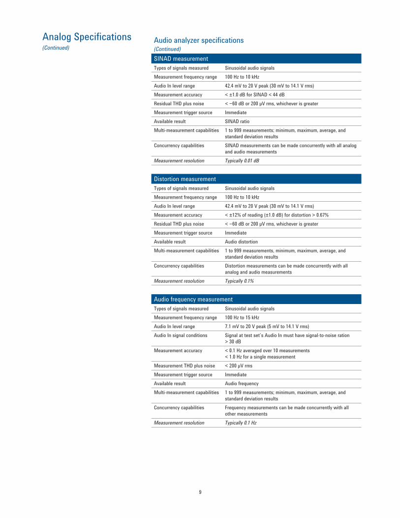
Audio analyzer specifications (Continued) SINAD measurementTypes of signals measured Sinusoidal audio signals Measurement frequency range 100 Hz to 10 kHz Audio In level range 42.4 mV to 20 V peak (30 mV to 14.1 V rms) Measurement accuracy < ±1.0 dB for SINAD < 44 dB Residual THD plus noise < −60 dB or 200 μV rms, whichever is greater Measurement trigger source Immediate Available result SINAD ratio Multi-measurement capabilities 1 to 999 measurements; minimum, maximum, average, and
standard deviation results Concurrency capabilities SINAD measurements can be made concurrently with all analog
and audio measurements Measurement resolution Typically 0.01 dB
Distortion measurementTypes of signals measured Sinusoidal audio signals Measurement frequency range 100 Hz to 10 kHz Audio In level range 42.4 mV to 20 V peak (30 mV to 14.1 V rms) Measurement accuracy < ±12% of reading (±1.0 dB) for distortion > 0.67% Residual THD plus noise < −60 dB or 200 μV rms, whichever is greater Measurement trigger source Immediate Available result Audio distortion Multi-measurement capabilities 1 to 999 measurements, minimum, maximum, average, and
standard deviation results Concurrency capabilities Distortion measurements can be made concurrently with all
analog and audio measurements Measurement resolution Typically 0.1%
Audio frequency measurementTypes of signals measured Sinusoidal audio signals Measurement frequency range 100 Hz to 15 kHz Audio In level range 7.1 mV to 20 V peak (5 mV to 14.1 V rms) Audio In signal conditions Signal at test set’s Audio In must have signal-to-noise ration
> 30 dB Measurement accuracy < 0.1 Hz averaged over 10 measurements
< 1.0 Hz for a single measurement Measurement THD plus noise < 200 μV rms Measurement trigger source Immediate Available result Audio frequency Multi-measurement capabilities 1 to 999 measurements; minimum, maximum, average, and
standard deviation results Concurrency capabilities Frequency measurements can be made concurrently with all
other measurements Measurement resolution Typically 0.1 Hz

10
1xEV-DO Call Processing Functionality
Resident formats 1xEV-DO Call processing timing tolerance Mobile transmissions must be typically within ±6 μs of
test set’s transmitted pilot channel clock timing for proper reverse channel acquisition
Overhead messages Sync message with real-time long code and system time update, quick configuration message, sector parameters message, and access parameters message
Protocol stack 1xEV-DO Release 0 using test application protocol (TAP – includes both FTAP and RTAP)
Base station parameters ACKChannelGain, DRCChannelGain, DataOffsetNom, DataOffset9k6, DataOffset19k2, DataOffset38k4, DataOffset76k8, and DataOffset153k6
Call control (one button commands) Access network open connection Access network close connection Access network close session Access terminal open connection Access terminal close connection
Supported applications FTAP and RTAP only Access parameters OpenLoopAdjust, ProbeInitialAdjust, ProbeNumStep,
PreambleLength, PowerStep, ProbeSequenceMax, and PreferredControlChannelCycle
System parameters ColorCode, CountryCode, SectorID, and SubnetMask Protocol status Idle, UATI request, session negotiation, session open,
session closing, paging, connect request, connection negotiation, connected, connection closing, and handoff
Forward control channel data rate Selectable between 38.4 or 78.6 kbps Session terminal displayed parameters
Session seed, hardware ID, assigned UATI, and assigned MAC index
Hardware ID types supported ESN, MEID, “NNNN” Activity factor 100% only AT directed packets User-adjustable percentage (0 up to 100%) of forward
traffic packets directed to the AT under test. Default value of 50% per AT minimum performance specification. Packets not direct to the AT under test are sent to another MAC address that is not in use
Limited TAP mode On or Off with default of Off. This field is required to be set to On if the AT uses a firmware revision that does not support the full test application protocol as required by standard
ACK channel bit fixed mode attribute
On or Off
FTAP mode Loopback Call limit Selectable On or Off. When On, the test set ignores all
access terminal access attempts Handoff support Hard handoff to new channel or band R-DRC fixed mode attribute On or Off. Default of On. When in the On state, the test
transmits the user-set forward traffic rate. When in the Off state, the test set transmits the forward configuration per the received DRC value transmitted by the AT
DRC length Fixed to 8 slots R-ACK channel mode Fixed to force decoding of each packet over its full number
of slots Session close timer 0 to 3240 minutes Configurable attributes Preferred control channel cycle: AT or AN specified Pilot drop 0 to 63 (0 to −31.5 dB)
11
1xEV-DO Call Processing Functionality (Continued)
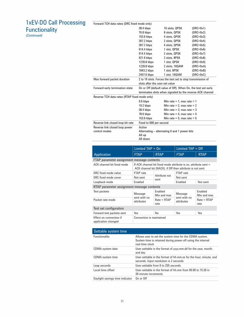
Forward TCH data rates (DRC fixed mode only)38.4 kbps76.8 kbps153.6 kbps307.2 kbps307.2 kbps614.4 kbps614.4 kbps921.6 kbps1228.8 kbps1228.8 kbps1843.2 kbps2457.6 kbps
16 slots, QPSK8 slots, QPSK4 slots, QPSK2 slots, QPSK4 slots, QPSK1 slot, QPSK2 slots, QPSK2 slots, 8PSK1 slot, QPSK2 slots, 16QAM1 slot, 8PSK1 slot, 16QAM
(DRC=0x1)(DRC=0x2)(DRC=0x3)(DRC=0x4)(DRC=0x5)(DRC=0x6)(DRC=0x7)(DRC=0x8)(DRC=0x9)(DRC=0xA)(DRC=0xB)(DRC=0xC)
Max forward packet duration 2 to 16 slots. Forces the test set to stop transmission of slots after the user-set value
Forward early termination state On or Off (default value of Off). When On, the test set early terminates slots when signaled by the reverse ACK channel
Reverse TCH data rates (RTAP fixed mode only) 9.6 kbps19.2 kbps38.4 kbps78.6 kbps153.6 kbps
Min rate = 1, max rate = 1Min rate = 2, max rate = 2Min rate = 3, max rate = 3Min rate = 4, max rate = 4Min rate = 5, max rate = 5
Reverse link closed loop bit rate Fixed to 600 per second Reverse link closed loop power control modes
Active Alternating – alternating 0 and 1 power bits All up All down
Limited TAP = On Limited TAP = OffApplication FTAP RTAP FTAP RTAPFTAP parameter assignment message contents ACK channel bit fixed mode If ACK channel bit fixed mode attribute is on, attribute sent =
ACK channel bit (NACK), if Off then attribute is not sent DRC fixed mode value FTAP rate
Attribute not sent
FTAP rate DRC fixed mode cover Not sent Not sentLoopback mode Enabled Enabled Not sentRTAP parameter assignment message contents Test packets
Message sent with no attributes
Enabled Min and max Message
sent with no attributes
Enabled Min and max
Packet rate mode Rate = RTAPrate
Rate = RTAP rate
Test set configuration Forward test packets sent Yes No Yes Yes Effect on connection if application changed
Connection is maintained
Settable system timeFunctionality Allows user to set the system time for the CDMA system.
System time is retained during power-off using the internal real-time clock
CDMA system date User-settable in the format of yyyy.mm.dd for the year, month, and day
CDMA system time User-settable in the format of hh.mm.ss for the hour, minute, and seconds. Input resolution is 2 seconds
Leap seconds User-settable from 0 to 255 seconds Local time offset User-settable in the format of hh.mm from 00.00 to 15.30 in
30 minute increments Daylight savings time indicator On or Off
12
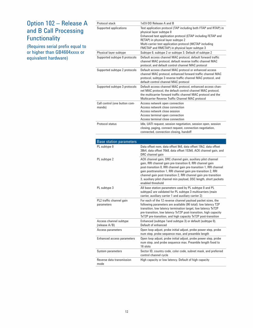
Option 102 – Release A and B Call Processing Functionality (Requires serial prefix equal to or higher than GB4604xxxx or equivalent hardware)
Protocol stack 1xEV-DO Release A and B Supported applications Test application protocol (TAP including both FTAP and RTAP) in
physical layer subtype 0 Enhanced test application protocol (ETAP including FETAP and RETAP) in physical layer subtype 2 Multi-carrier test application protocol (MCTAP including FMCTAP and RMCTAP) in physical layer subtype 3
Physical layer subtype Subtype 0, subtype 2 or subtype 3. Default of subtype 2 Supported subtype 0 protocols Default access channel MAC protocol, default forward traffic
channel MAC protocol, default reverse traffic channel MAC protocol, and default control channel MAC protocol
Supported subtype 2 protocols Default access channel MAC protocol or enhanced access channel MAC protocol, enhanced forward traffic channel MAC protocol, subtype 3 reverse traffic channel MAC protocol, and default control channel MAC protocol
Supported subtype 3 protocols Default access channel MAC protocol, enhanced access chan-nel MAC protocol, the default control channel MAC protocol, the multicarrier forward traffic channel MAC protocol and the Multicarrier Reverse Traffic Channel MAC protocol
Call control (one button com-mands)
Access network open connection Access network close connection Access network close session Access terminal open connection Access terminal close connection
Protocol status Idle, UATI request, session negotiation, session open, session closing, paging, connect request, connection negotiation, connected, connection closing, handoff
Base station parametersPL subtype 0 Data offset nom, data offset 9k6, data offset 19k2, data offset
38k4, data offset 76k8, data offset 153k6, ACK channel gain, and DRC channel gain
PL subtype 2 ACK channel gain, DRC channel gain, auxiliary pilot channel gain, RRI channel gain pre-transition 0, RRI channel gain post-transition 0, RRI channel gain pre-transition 1, RRI channel gain posttransition 1, RRI channel gain pre-transition 2, RRI channel gain post-transition 2, RRI channel gain pre-transition 3, auxiliary pilot channel min payload, DSC length, short packets enabled threshold
PL subtype 3 All base station parameters used by PL subtype 0 and PL subtype2 are validated for PL subtype 3 multicarriers (main carrier, auxiliary carrier 1 and auxiliary carrier 2)
PL2 traffic channel gain parameters
For each of the 12 reverse channel payload packet sizes, the following parameters are available (96 total): low latency T2P transition, low latency termination target, low latency TxT2P pre-transition, low latency TxT2P post-transition, high capacity TxT2P pre-transition, and high capacity TxT2P post-transition
Access channel subtype (release A/B)
Enhanced (subtype 1and subtype 3) or default (subtype 0). Default of enhanced
Access parameters Open loop adjust, probe initial adjust, probe power step, probe num step, probe sequence max, and preamble length
Enhanced access parameters Open loop adjust, probe initial adjust, probe power step, probe num step, and probe sequence max. Preamble length fixed to 16 slots
System parameters Sector ID, country code, color code, subnet mask, and preferred control channel cycle
Reverse data transmission mode
High capacity or low latency. Default of high capacity
13
Option 102 – Release A and B Call Processing Functionality (Continued)
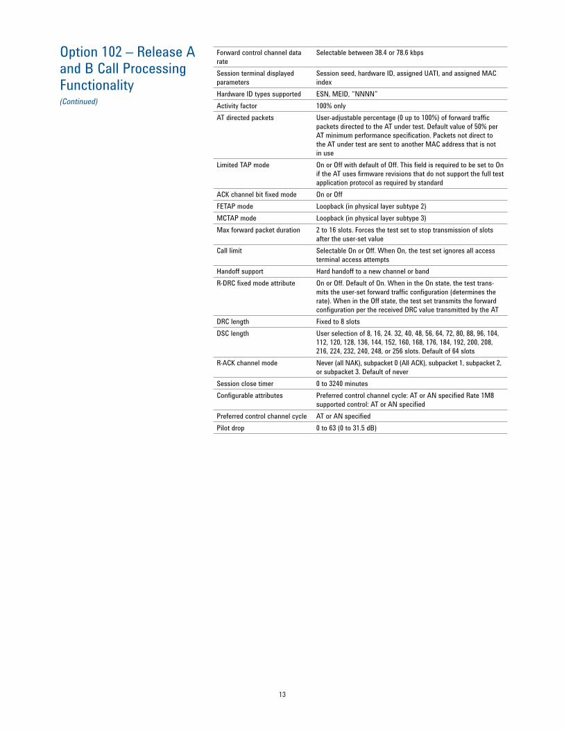
Forward control channel data rate
Selectable between 38.4 or 78.6 kbps
Session terminal displayed parameters
Session seed, hardware ID, assigned UATI, and assigned MAC index
Hardware ID types supported ESN, MEID, “NNNN” Activity factor 100% only AT directed packets User-adjustable percentage (0 up to 100%) of forward traffic
packets directed to the AT under test. Default value of 50% per AT minimum performance specification. Packets not direct to the AT under test are sent to another MAC address that is not in use
Limited TAP mode On or Off with default of Off. This field is required to be set to On if the AT uses firmware revisions that do not support the full test application protocol as required by standard
ACK channel bit fixed mode On or Off FETAP mode Loopback (in physical layer subtype 2) MCTAP mode Loopback (in physical layer subtype 3) Max forward packet duration 2 to 16 slots. Forces the test set to stop transmission of slots
after the user-set value Call limit Selectable On or Off. When On, the test set ignores all access
terminal access attempts Handoff support Hard handoff to a new channel or band R-DRC fixed mode attribute On or Off. Default of On. When in the On state, the test trans-
mits the user-set forward traffic configuration (determines the rate). When in the Off state, the test set transmits the forward configuration per the received DRC value transmitted by the AT
DRC length Fixed to 8 slots DSC length User selection of 8, 16, 24. 32, 40, 48, 56, 64, 72, 80, 88, 96, 104,
112, 120, 128, 136, 144, 152, 160, 168, 176, 184, 192, 200, 208, 216, 224, 232, 240, 248, or 256 slots. Default of 64 slots
R-ACK channel mode Never (all NAK), subpacket 0 (All ACK), subpacket 1, subpacket 2, or subpacket 3. Default of never
Session close timer 0 to 3240 minutes Configurable attributes Preferred control channel cycle: AT or AN specified Rate 1M8
supported control: AT or AN specified Preferred control channel cycle AT or AN specified Pilot drop 0 to 63 (0 to 31.5 dB)
14
Option 102 – Release A and B Call Processing Functionality (Continued)
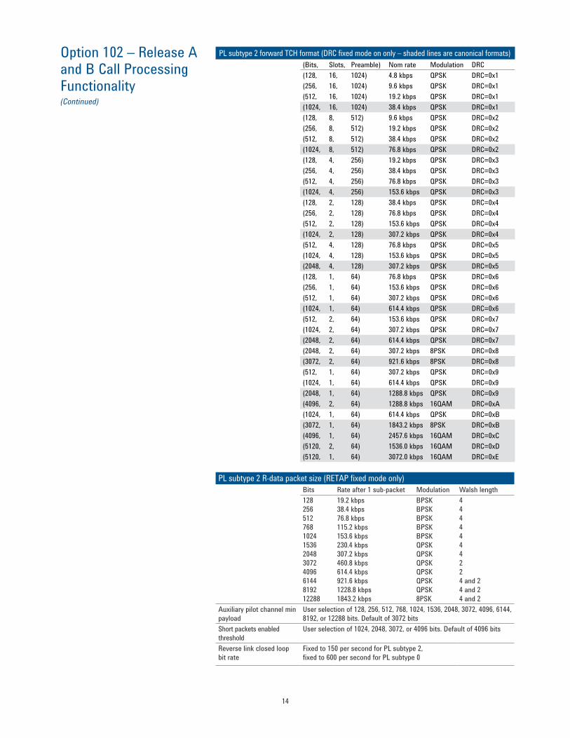
PL subtype 2 forward TCH format (DRC fixed mode on only – shaded lines are canonical formats)(Bits, Slots, Preamble) Nom rate Modulation DRC (128, 16, 1024) 4.8 kbps QPSK DRC=0x1 (256, 16, 1024) 9.6 kbps QPSK DRC=0x1 (512, 16, 1024) 19.2 kbps QPSK DRC=0x1 (1024, 16, 1024) 38.4 kbps QPSK DRC=0x1 (128, 8, 512) 9.6 kbps QPSK DRC=0x2 (256, 8, 512) 19.2 kbps QPSK DRC=0x2 (512, 8, 512) 38.4 kbps QPSK DRC=0x2 (1024, 8, 512) 76.8 kbps QPSK DRC=0x2 (128, 4, 256) 19.2 kbps QPSK DRC=0x3 (256, 4, 256) 38.4 kbps QPSK DRC=0x3 (512, 4, 256) 76.8 kbps QPSK DRC=0x3 (1024, 4, 256) 153.6 kbps QPSK DRC=0x3 (128, 2, 128) 38.4 kbps QPSK DRC=0x4 (256, 2, 128) 76.8 kbps QPSK DRC=0x4 (512, 2, 128) 153.6 kbps QPSK DRC=0x4 (1024, 2, 128) 307.2 kbps QPSK DRC=0x4 (512, 4, 128) 76.8 kbps QPSK DRC=0x5 (1024, 4, 128) 153.6 kbps QPSK DRC=0x5 (2048, 4, 128) 307.2 kbps QPSK DRC=0x5 (128, 1, 64) 76.8 kbps QPSK DRC=0x6 (256, 1, 64) 153.6 kbps QPSK DRC=0x6 (512, 1, 64) 307.2 kbps QPSK DRC=0x6 (1024, 1, 64) 614.4 kbps QPSK DRC=0x6 (512, 2, 64) 153.6 kbps QPSK DRC=0x7 (1024, 2, 64) 307.2 kbps QPSK DRC=0x7 (2048, 2, 64) 614.4 kbps QPSK DRC=0x7 (2048, 2, 64) 307.2 kbps 8PSK DRC=0x8 (3072, 2, 64) 921.6 kbps 8PSK DRC=0x8 (512, 1, 64) 307.2 kbps QPSK DRC=0x9 (1024, 1, 64) 614.4 kbps QPSK DRC=0x9 (2048, 1, 64) 1288.8 kbps QPSK DRC=0x9 (4096, 2, 64) 1288.8 kbps 16QAM DRC=0xA (1024, 1, 64) 614.4 kbps QPSK DRC=0xB (3072, 1, 64) 1843.2 kbps 8PSK DRC=0xB (4096, 1, 64) 2457.6 kbps 16QAM DRC=0xC (5120, 2, 64) 1536.0 kbps 16QAM DRC=0xD (5120, 1, 64) 3072.0 kbps 16QAM DRC=0xE
PL subtype 2 R-data packet size (RETAP fixed mode only)
Bits Rate after 1 sub-packet Modulation Walsh length128 256 512 768 1024 1536 2048 3072 4096 6144 8192 12288
19.2 kbps 38.4 kbps 76.8 kbps 115.2 kbps 153.6 kbps 230.4 kbps 307.2 kbps 460.8 kbps 614.4 kbps 921.6 kbps 1228.8 kbps 1843.2 kbps
BPSKBPSK BPSK BPSK BPSK QPSK QPSK QPSK QPSK QPSK QPSK 8PSK
4 4 4 4 4 4 4 2 2 4 and 2 4 and 2 4 and 2
Auxiliary pilot channel min payload
User selection of 128, 256, 512, 768, 1024, 1536, 2048, 3072, 4096, 6144, 8192, or 12288 bits. Default of 3072 bits
Short packets enabled threshold
User selection of 1024, 2048, 3072, or 4096 bits. Default of 4096 bits
Reverse link closed loop bit rate
Fixed to 150 per second for PL subtype 2, fixed to 600 per second for PL subtype 0

15
Option 102 – Release A and B Call Processing Functionality (Continued)
Reverse link closed loop power control modes
ActiveAlternating – alternating 0 and 1 power bitsAll upAll down
Enhanced test applicationprotocol = FETAP
Enhanced test applicationprotocol = RETAP
FETAP parameter assignment message DRC value fixed mode If DRCValueFixedMode attribute is On, attribute sent:
F-traffic format If DRCValueFixedMode attribute is Off, attribute not sent
DRC cover fixed mode Attribute not sent Ack channel bit fixed mode If Ack channel bit fixed mode attribute is On,
Attribute sent: ACK channel bit (fixed setting) If Ack channel bit fixed mode attribute is Off, attribute not sent
Loopback mode Attribute sent: Enable Attribute not sent Ack channel modulation type fixed mode
Ack channel bit fixed mode attribute is On: Attribute sent: ACK channel modulation (reverse ACK subtype 2) Otherwise: Attribute not sent
RETAP parameter assignment message RETAP test packets enabled
Attribute not sent
Attribute sent: Enable (0x01) Packet rate mode Attribute not sentPacket payload size mode Attribute sent:
min = R-data packet size max = R-data packet size
Enhanced access channel rate mode
Attribute sent: Enhanced access rate
Burst period mode
Attribute not sent
Attribute sent: LinkFlowID based on R-data transmission mode Period = Burst period
Burst size mode
Attribute sent: LinkFlowID based on R-data transmission mode Size = Burst size
16
Option 103 – Multi-carrier Call Processing Functionality(requires E5515E or E5515C with serial prefix equal to or higher than GB4604xxxx or equivalent hardware and a license for Option 102 1xEV-DO Release A and B feature option and Option 406 Multi-Unit Sync feature option)
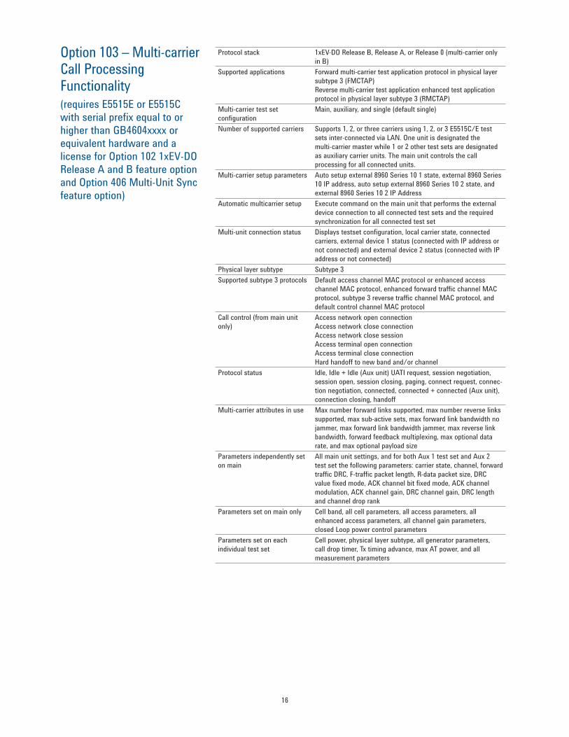
Protocol stack 1xEV-DO Release B, Release A, or Release 0 (multi-carrier only in B)
Supported applications Forward multi-carrier test application protocol in physical layer subtype 3 (FMCTAP) Reverse multi-carrier test application enhanced test application protocol in physical layer subtype 3 (RMCTAP)
Multi-carrier test set configuration
Main, auxiliary, and single (default single)
Number of supported carriers Supports 1, 2, or three carriers using 1, 2, or 3 E5515C/E test sets inter-connected via LAN. One unit is designated the multi-carrier master while 1 or 2 other test sets are designated as auxiliary carrier units. The main unit controls the call processing for all connected units.
Multi-carrier setup parameters Auto setup external 8960 Series 10 1 state, external 8960 Series 10 IP address, auto setup external 8960 Series 10 2 state, and external 8960 Series 10 2 IP Address
Automatic multicarrier setup Execute command on the main unit that performs the external device connection to all connected test sets and the required synchronization for all connected test set
Multi-unit connection status Displays testset configuration, local carrier state, connected carriers, external device 1 status (connected with IP address or not connected) and external device 2 status (connected with IP address or not connected)
Physical layer subtype Subtype 3 Supported subtype 3 protocols Default access channel MAC protocol or enhanced access
channel MAC protocol, enhanced forward traffic channel MAC protocol, subtype 3 reverse traffic channel MAC protocol, and default control channel MAC protocol
Call control (from main unit only)
Access network open connection Access network close connection Access network close session Access terminal open connection Access terminal close connection Hard handoff to new band and/or channel
Protocol status Idle, Idle + Idle (Aux unit) UATI request, session negotiation, session open, session closing, paging, connect request, connec-tion negotiation, connected, connected + connected (Aux unit), connection closing, handoff
Multi-carrier attributes in use Max number forward links supported, max number reverse links supported, max sub-active sets, max forward link bandwidth no jammer, max forward link bandwidth jammer, max reverse link bandwidth, forward feedback multiplexing, max optional data rate, and max optional payload size
Parameters independently set on main
All main unit settings, and for both Aux 1 test set and Aux 2 test set the following parameters: carrier state, channel, forward traffic DRC, F-traffic packet length, R-data packet size, DRC value fixed mode, ACK channel bit fixed mode, ACK channel modulation, ACK channel gain, DRC channel gain, DRC length and channel drop rank
Parameters set on main only Cell band, all cell parameters, all access parameters, all enhanced access parameters, all channel gain parameters, closed Loop power control parameters
Parameters set on each individual test set
Cell power, physical layer subtype, all generator parameters, call drop timer, Tx timing advance, max AT power, and all measurement parameters

17
1xEV-DO Test Mode Functionality
Protocol stack 1xEV-DO Release 0 overhead messages only with fixed traffic channel
Base station parameters ACKChannelGain, DRCChannelGain, DataOffsetNom, DataOffset9k6, DataOffset19k2, DataOffset38k4, DataOffset76k8, and DataOffset153k6
Call control (one button commands)
None
Access parameters OpenLoopAdjust, ProbeInitialAdjust, ProbeNumStep, PreambleLength, PowerStep, ProbeSequenceMax, and PreferredControlChannelCycle
System parameters ColorCode, CountryCode, SectorID, and SubnetMask Protocol status No protocol support other than overhead messages Forward control channel data rate
Selectable between 38.4 or 78.6 kbps
Activity factor 100% only AT directed packets Adjustable percentage (0 to 100%) of forward traffic packets di-
rected to the AT under test. Default value of 50% per AT minimum performance specification. Packets not direct to the AT under test are sent to another MAC address that is not in use
MAC index 5 to 63. Must be set to match AT expected value
Pilot drop 0 to 63 (0 to −31.5 dB) Forward TCH data rates 38.4 kbps
76.8 kbps 153.6 kbps 307.2 kbps 307.2 kbps 614.4 kbps 614.4 kbps 921.6 kbps 1228.8 kbps 1228.8 kbps 1843.2 kbps 2457.6 kbps
16 slots, QPSK8 slots, QPSK4 slots, QPSK2 slots, QPSK4 slots, QPSK1 slot, QPSK2 slots, QPSK2 slots, 8PSK1 slot, QPSK2 slots, 16QAM1 slot, 8PSK1 slot, 16QAM
(DRC=0x1)(DRC=0x2)(DRC=0x3)(DRC=0x4)(DRC=0x5)(DRC=0x6)(DRC=0x7)(DRC=0x8)(DRC=0x9)(DRC=0xA)(DRC=0xB)(DRC=0xC)
Expected reverse TCH data rate
9.6 kbps19.2 kbps38.4 kbps78.6 kbps153.6 kbps
Reverse link closed loop bit rate
Fixed to 600 per second
Reverse link closed loop power control modes
Alternating – alternating 0 and 1 power bits All up All down
Settable system timeFunctionality Allows user to set the system time for the CDMA system. System
time is retained during power-off using the internal real-time clock
CDMA system date Settable in the format yyyy.mm.dd for the year, month, and day CDMA system time Settable in the format of hh.mm.ss for the hour, minute, and
seconds. Input resolution is 2 seconds Leap seconds Settable from 0 to 255 seconds Local time offset Settable in the format of hh.mm from 00.00 to 15.30 in 30 minute
increments Daylight savings time indicator On or Off

18
1xEV-DO RF GeneratorRF generator level accuracy is derived from 99th percentile observationswith 95 percent confidence (corresponds to an expanded uncertainty with a 95 percent confidence (k=2)) at ambient conditions, then qualified to include the environmental effects of temperature and humidity.
ChannelsAdditive white Gaussian noise source
Yes
AWGN bandwidth Typically 1.8 MHz < BW < 2.1 MHz 1xEV-DO cell with the following multiplexed channels
F-Pilot, F-MAC, F-CCH, and F-TCH
PN offset Selectable from 0 to 511
FrequencyFrequency range US cellular band 860.04-893.97 MHz channels
1-799, 991-1023, 1024-1323, 1324-1424 US PCS band 1930-1990 MHz, channels 0-1199 Korean PCS band 1840-1870 MHz, channels 0-599 Japan CDMA band Approx. 832-869.9875 MHz,
channels 1-799, 801-1039, 1041-1199, 1201-1600
IMT-2000 band 2110-2169.950 MHz, channels 0-1199 NMT-450 band Approx. 421-494 MHz, channels 1-300,
539-871, 1039-1473, 1792-2016 Secondary 800 MHz band Approx. 851-869 MHz, and
935-940 MHz, channels 0-719, 720-919 US PCS 1.9 GHz band 1930-1995 MHz, channels 0-1299 AWS band 2110-2155 MHz, channels 0-899Cellular Upper 700 band 776-788 MHz, channels 0-240 400 MHz European PAMR band
420-494 MHz, channels 1-2016
800 MHz PAMR band 915-921 MHz, channels 0-239 700 MHz Public Safety Band
757-769 MHz, channels 0-240
Lower 700 MHz Band 728-746 MHz, channels 0-360 US in-flight band 849.750-850.25 MHz and 894.750-
895.25 MHz, channels 2, 4, 6, 8, 10Frequency setting By channel number
AmplitudeOutput port control User control of RF source routing to either the RF IN/OUT port or
the RF OUT ONLY port RF IN/OUT composite signal level
Sum of the user-set values of the 1xEV-DO cell power and the AWGN source
RF IN/OUT 1xEV-DO cell output level range (AWGN off)
−120 dBm/1.23 MHz to −13 dBm/1.23 MHz
RF IN/OUT AWGN output level range
−120 dBm/1.23 MHz to −20 dBm/1.23 MHz over-range available with reduced performance to −15 dBm/1.23 MHz
RF IN/OUT 1xEV-DO cell absolute output level accuracy (AWGN off)
< ±1.1 dB, −109 to −15 dBm/1.23 MHz typically ±0.62 dB, −109 to −15 dBm/1.23 MHz
RF IN/OUT composite absolute output level accuracy (AWGN on)
< ±1.2 dB, −109 to −20 dBm/1.23 MHz typically ±0.7 dB, −109 to −20 dBm/1.23 MHz
RF IN/OUT reverse power +37 dBm peak (5 W peak) RF IN/OUT VSWR < 1.14:1
< 1.2:1 < 1.32:1
400 to 1000 MHz 1700 to 2000 MHz 2010 to 2180 MHz
RF OUT ONLY composite signal level
Sum of the user-set values of 1xEV-DO cell power and the AWGN source
RF OUT ONLY 1xEV-DO cell output level range (AWGN off)
−115 dBm/1.23 MHz to −5 dBm/1.23 MHz
RF OUT ONLY AWGN output level range
−115 dBm/1.23 MHz to −12 dBm/1.23 MHz over-range available with reduced performance to −7 dBm/1.23 MHz

19
1xEV-DO RF Generator (Continued)
1xEV-DO RF Generator(Option 102 – Release A)
1xEV-DO RF Analyzer(measurements only)
RF out only 1xEV-DO cell absolute output level accuracy (AWGN off)
< ±1.1 dB, −109 to −7 dBm/1.23 MHz typically < ±0.62 dB, −109 to −7 dBm/1.23 MHz
RF out only composite absolute output level accuracy (AWGN on)
< ±1.2 dB, −109 to −12 dBm/1.23 MHz typically < ±0.7 dB, −109 to −12 dBm/1.23 MHz
RF out only reverse power +24 dBm peak (250 mW peak) RF out only VSWR Typically < 1.3:1 for 400 to 500 MHz, < 1.4:1 for 800 to 1000 MHz,
and < 1.45:1 for 1.7 to 2.2 GHzIsolation (from RF out only port to RF in/out when the RF source is routed to the RF out only port
Typically > 40 dB
AWGN channel relative level range
Settable to ±35 dB relative to the total power (user-set 1xEV-DO cell power plus AWGN power) with 0.01 dB resolution
Relative AWGN level accuracy Typically < ±0.2 dB for AWGN levels of less than or equal to ±20 from the total set RF power. Useable to ±35 relative levels from total RF power with degraded relative level accuracy
1xEV-DO modulationModulation type QPSK, 8PSK, or 16QAM depending on F-TCH data rate Modulation quality Residual rho Residual EVM
> 0.99 < 10%, typically < 4%
Carrier feedthrough Typically < −35 dBc
AmplitudeH-ARQ/L-ARQ relative channel level
−6.00 to −30 dB, default of −9 dB
P-ARQ relative channel level −6.00 to −30 dB, default of −9 dB RPC relative channel level −6.00 to −30 dB, default of −9 dB
1xEV-DO modulationH-ARQ modulation type Bi-polar keying or on-off keying, default of bi-polar keying Frequency range (reverse channels)
US cellular band 1-799, 991-1023, 1024-1323, 1324-1424
US PCS band 0-1199 Korean PCS band 0-599 Japan CDMA band 1-799, 801-1039, 1041-1199,
1201-1600 IMT-2000 band 0-1199 NMT-450 band 1-300, 539-871, 1039-1473,
1792-2016 Secondary 800 band 0-719, 720-919 US PCS 1.9 GHz band 0-1299 AWS band 0-899 400 MHz European PAMR band 410-484 MHz, channels 1-2016 800 MHz PAMR band 870-876 MHz, channels 0-239 700 MHz Public Safety Band 787-799 MHz, channels 0-240 Lower 700 MHz Band 698-716 MHz, channels 0-360
Input level range −71 to +35 dBm/1.23 MHz
Receiver rangingAuto mode Autoranges to the ideal RF power level for the nominally
expected open loop response. Provides calibrated results if actual received power is within ±9 dB of the expected open loop power
Manual mode User enters expected power. If the Active mode is selected, the test set uses closed loop power control to drive the mobile to the expected power. Otherwise, the mobile’s Tx power must be within ±9 dB of the expected power to provide calibrated results

20
1xEV-DO Analyzer 1xEV-DO modulationInput frequency ranges 411 to 484 MHz
800 to 1000 MHz 1700 to 2000 MHz
Detector type Thermal detector Maximum input level +37 dBm peak (5 W peak) Measurement range −10 to +30 dBm Measurement level ranging Auto Measurement data capture period
10 ms
Measurement trigger 1.67 ms (slot trigger) Measurement result Average power Concurrency support Average power measurements can be made concurrently with all
1xEV-DO measurements that support concurrency Measurement accuracy (Accuracy with 10 internal averages, all up power control bits
and R-TCH rate set to 153.6 kbps): −10 to +30 dBm 400 to 500 MHz < ±6.9%, typically < ±3.0%
800 to 1000 MHz < ±6.2%, typically < ±3.0%1700 to 2000 MHz < ±7.4%, RF out only port < ±8.2%,
typically < ±3.3%Measurement repeatability Typically < ±0.05 dB Measurement resolution 0.01 dBm Zero function Auto zeroes (no user control)
Access probe power measurementInput frequency ranges 411 to 420 MHz
450 to 484 MHz 821 to 934 MHz 1700 to 1980 MHz
Measurement method Measures the total power in a 1.23 MHz bandwidth centered on the active reverse channel center frequency
Measurement data capture period
1.67 ms
Measurement trigger Amplitude rise only Maximum input level +37 dBm/1.23 MHz peak (5 W peak) Measurement range −54 to +30 dBm Measurement level ranging Auto and manual Measurement accuracy < ±1 dB 15 to 55 °C, typically < ±0.5 dB (Calibrated against
average power and within ±10 degrees of calibration temperature. Calibration must occur between 20 to 55 °C)
Measurement result Access probe power in a 1.23 MHz bandwidth Concurrency capabilities None
Tuned channel power measurementInput frequency ranges 411 to 420 MHz
450 to 484 MHz821 to 934 MHz1700 to 1980 MHz
Measurement method Measures the total power in a 1.23 MHz bandwidth centered on the active reverse channel center frequency
Measurement data capture period
0.3125 ms (very fast mode) and 1.67 ms (fast mode)
Measurement trigger 1.67 ms clock (slot trigger) Maximum input level +37 dBm/1.23 MHz peak (5 W peak)

21
1xEV-DO Analyzer (Continued)
Measurement range −61 to +30 dBm, usable to < −69 dBm/1.23 MHz with reduced accuracy
Measurement level ranging Auto and manualMeasurement accuracy < ±1 dB 15 to 55 °C for the fast mode, typically < ±0.5 dB
< ±1.1 dB for 15 to 55 °C for the very fast mode, typically < ±0.5 dB. (Calibrated against average power and within ±10 degrees of calibration temperature. Calibration must occur between 20 to 55 °C)
Measurement resolution 0.01 dBm/1.23 MHzMeasurement result Channel power in a 1.23 MHz bandwidthConcurrency capabilities Channel power measurements can be made concurrently with all
1xEV-DO measurements that support concurrencyCalibrate function Calibrates the channel power measurement over the entire
operating frequency range of the test set against the average power measurement; no external cabling is required
Calibration time Typically < 120 seconds
Modulation quality measurementInput frequency ranges 411 to 484 MHz
800 to 1000 MHz 1700 to 2000 MHz
Measurement chip rate 1.2288 McpsModulation measurement method
Multi-code rho and EVM with code domain results
Maximum input level +37 dBm/1.23 MHz peak (5 W peak)Input level range −25 to +30 dBm/1.23 MHz for reverse rates of 9.6 kbps, usable
to −50 dBm/1.23 MHz at 9.6 kbps with reduced accuracy; sensitivity reduces with increased reverse data rates
Modulation quality measurement range
1 to 40% EVM (For signals with < ±6 μs time error and < ±1 kHz frequency error)
Measurement interval 1 to 8 slots (1.67 up to 13.33 ms) for PL subtype 0 1 to 4 slots (1.67 up to 6.67 ms) for PL subtype 2
Measurement trigger 27 ms (frame trigger)Modulation quality measurement accuracy
< ±1.25 rms + residual error for 1% < EVM < 20%
Modulation quality measurement residualsResidual rho Residual EVM Residual time error Frequency error sidual code domain power
> 0.999 < 4% rms, typically < 3.1% ±0.11 μs ±15 Hz plus timebase error < −35 dBc
Code domain power relative measurement accuracy
< ±0.005 relative to a total power for linear code domain powers from 0.05 to 1.0
Code domain resultsCode domain power graph Displays the power in all 16 Walsh coded channels (16 bit) for
both the I channel and the Q channel; reported power in each graph is relative to the total combined I and Q channel power; red bars indicate active channels, while yellow bars indicate inactive channels
Code domain table Displays the Walsh code, spread factor, code domain power (at SF=16), total code domain power, and code power relative to the R-Pilot channel for each active reverse channel; possible active channels R-Pilot, R-RRI, R-ACK, R-DRC, and R-TCH
Code domain power and noise graph
Displays the power and noise in all 16 Walsh coded channels (16 bits) for both the I channel and the Q channel; reported power in each graph is relative to the total combined I and Q channel power, red bars indicate active channels, while yellow bars indicate noise in each channel
22
1xEV-DO Analyzer (Continued)
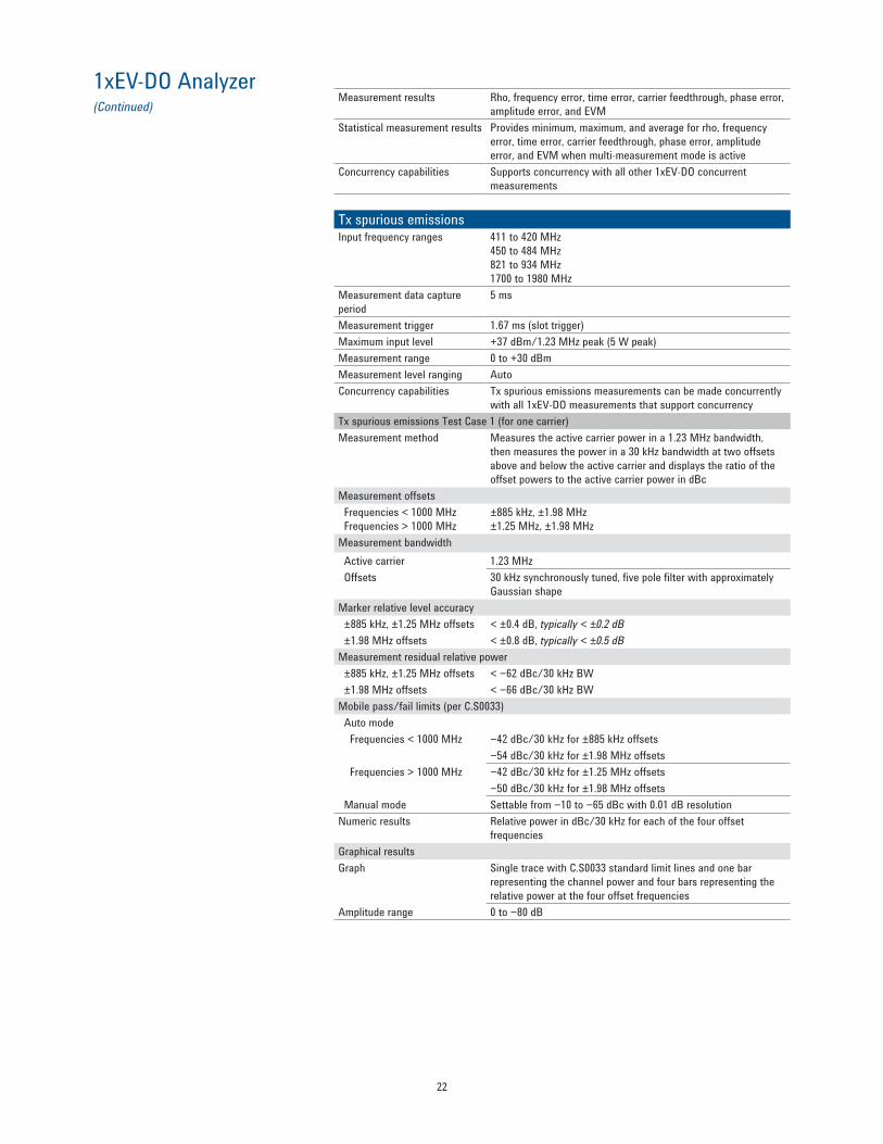
Measurement results Rho, frequency error, time error, carrier feedthrough, phase error, amplitude error, and EVM
Statistical measurement results Provides minimum, maximum, and average for rho, frequency error, time error, carrier feedthrough, phase error, amplitude error, and EVM when multi-measurement mode is active
Concurrency capabilities Supports concurrency with all other 1xEV-DO concurrent measurements
Tx spurious emissionsInput frequency ranges 411 to 420 MHz
450 to 484 MHz 821 to 934 MHz 1700 to 1980 MHz
Measurement data capture period
5 ms
Measurement trigger 1.67 ms (slot trigger)Maximum input level +37 dBm/1.23 MHz peak (5 W peak)Measurement range 0 to +30 dBmMeasurement level ranging AutoConcurrency capabilities Tx spurious emissions measurements can be made concurrently
with all 1xEV-DO measurements that support concurrencyTx spurious emissions Test Case 1 (for one carrier)Measurement method Measures the active carrier power in a 1.23 MHz bandwidth,
then measures the power in a 30 kHz bandwidth at two offsets above and below the active carrier and displays the ratio of the offset powers to the active carrier power in dBc
Measurement offsets Frequencies < 1000 MHz Frequencies > 1000 MHz
±885 kHz, ±1.98 MHz ±1.25 MHz, ±1.98 MHz
Measurement bandwidth Active carrier 1.23 MHz Offsets 30 kHz synchronously tuned, five pole filter with approximately
Gaussian shapeMarker relative level accuracy ±885 kHz, ±1.25 MHz offsets < ±0.4 dB, typically < ±0.2 dB ±1.98 MHz offsets < ±0.8 dB, typically < ±0.5 dBMeasurement residual relative power ±885 kHz, ±1.25 MHz offsets < −62 dBc/30 kHz BW ±1.98 MHz offsets < −66 dBc/30 kHz BWMobile pass/fail limits (per C.S0033) Auto mode Frequencies < 1000 MHz −42 dBc/30 kHz for ±885 kHz offsets
−54 dBc/30 kHz for ±1.98 MHz offsets Frequencies > 1000 MHz −42 dBc/30 kHz for ±1.25 MHz offsets
−50 dBc/30 kHz for ±1.98 MHz offsets Manual mode Settable from −10 to −65 dBc with 0.01 dB resolutionNumeric results Relative power in dBc/30 kHz for each of the four offset
frequenciesGraphical resultsGraph Single trace with C.S0033 standard limit lines and one bar
representing the channel power and four bars representing the relative power at the four offset frequencies
Amplitude range 0 to −80 dB
23
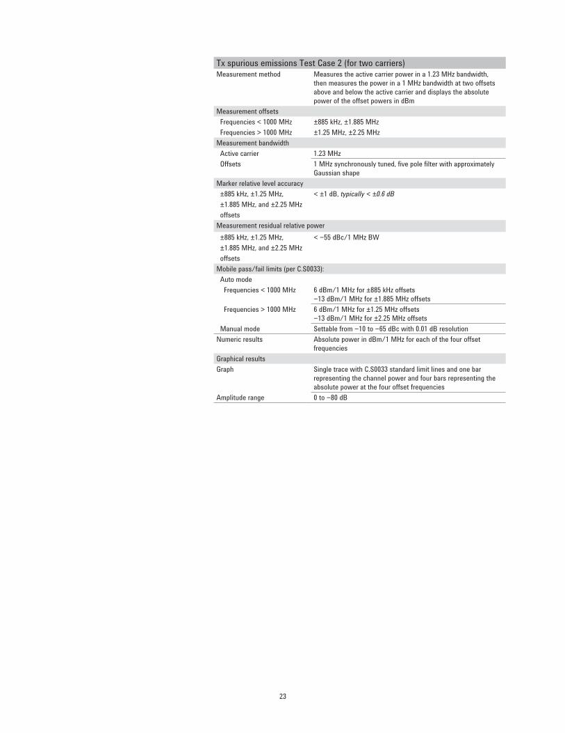
Tx spurious emissions Test Case 2 (for two carriers)Measurement method Measures the active carrier power in a 1.23 MHz bandwidth,
then measures the power in a 1 MHz bandwidth at two offsets above and below the active carrier and displays the absolute power of the offset powers in dBm
Measurement offsets Frequencies < 1000 MHz ±885 kHz, ±1.885 MHz Frequencies > 1000 MHz ±1.25 MHz, ±2.25 MHzMeasurement bandwidth Active carrier 1.23 MHz Offsets 1 MHz synchronously tuned, five pole filter with approximately
Gaussian shapeMarker relative level accuracy ±885 kHz, ±1.25 MHz, < ±1 dB, typically < ±0.6 dB ±1.885 MHz, and ±2.25 MHz offsetsMeasurement residual relative power ±885 kHz, ±1.25 MHz, < −55 dBc/1 MHz BW ±1.885 MHz, and ±2.25 MHz offsetsMobile pass/fail limits (per C.S0033): Auto mode Frequencies < 1000 MHz 6 dBm/1 MHz for ±885 kHz offsets
−13 dBm/1 MHz for ±1.885 MHz offsets Frequencies > 1000 MHz 6 dBm/1 MHz for ±1.25 MHz offsets
−13 dBm/1 MHz for ±2.25 MHz offsets Manual mode Settable from −10 to −65 dBc with 0.01 dB resolutionNumeric results Absolute power in dBm/1 MHz for each of the four offset
frequenciesGraphical resultsGraph Single trace with C.S0033 standard limit lines and one bar
representing the channel power and four bars representing the absolute power at the four offset frequencies
Amplitude range 0 to −80 dB
24
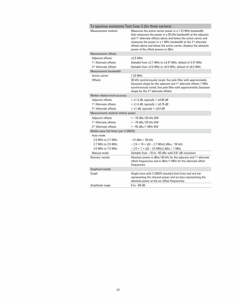
Tx spurious emissions Test Case 3 (for three carriers)Measurement method Measures the active carrier power in a 1.23 MHz bandwidth,
then measures the power in a 30 kHz bandwidth at the adjacent and 1st alternate offsets above and below the active carrier and measures the power in a 1 MHz bandwidth at the 2nd alternate offsets above and below the active carrier, displays the absolute power of the offset powers in dBm
Measurement offsets Adjacent offsets ±2.5 MHz 1st Alternate offsets Settable from ±2.7 MHz to ±3.47 MHz, default of 3.47 MHz 2nd Alternate offsets Settable from ±3.5 MHz to ±6.5 MHz, default of ±6.5 MHzMeasurement bandwidth Active carrier 1.23 MHz Offsets 30 kHz synchronously tuned, five pole filter with approximately
Gaussian shape for the adjacent and 1st alternate offsets 1 MHz synchronously tuned, five pole filter with approximately Gaussian shape for the 2nd alternate offsets
Marker relative level accuracy Adjacent offsets < ±1.3 dB, typically < ±0.65 dB 1st Alternate offsets < ±1.4 dB, typically < ±0.75 dB 2nd Alternate offsets < ±1 dB, typically < ±0.6 dBMeasurement residual relative power Adjacent offsets < −70 dBc/30 kHz BW 1st Alternate offsets < −70 dBc/30 kHz BW 2nd Alternate offsets < −55 dBc/1 MHz BWMobile pass/fail limits (per C.S0033): Auto mode 2.5 MHz to 2.7 MHz −14 dBm / 30 kHz 2.7 MHz to 3.5 MHz − [14 + 15 × (Δf – 2.7 MHz)] dBm / 30 kHz 3.5 MHz to 7.5 MHz − [13 + 1 × (Δf – 3.5 MHz)] dBm / 1 MHz Manual mode Settable from −10 to −65 dBc with 0.01 dB resolutionNumeric results Absolute power in dBm/30 kHz for the adjacent and 1st alternate
offset frequencies and in dBm/1 MHz for the alternate offset frequencies
Graphical resultsGraph Single trace with C.S0033 standard limit lines and one bar
representing the channel power and six bars representing the absolute power at the six offset frequencies
Amplitude range 0 to −80 dB
25
1xEV-DO Analyzer (Continued)
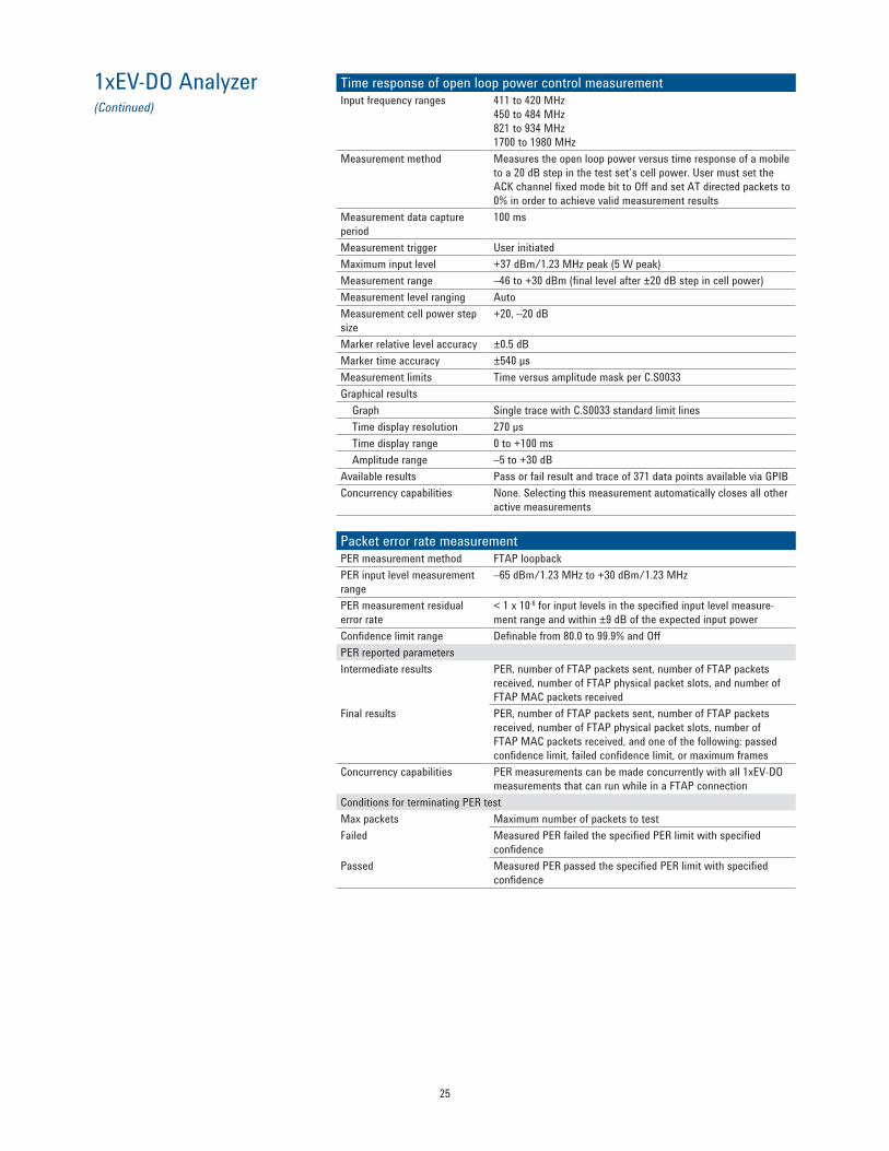
Time response of open loop power control measurement Input frequency ranges 411 to 420 MHz
450 to 484 MHz 821 to 934 MHz 1700 to 1980 MHz
Measurement method Measures the open loop power versus time response of a mobile to a 20 dB step in the test set’s cell power. User must set the ACK channel fixed mode bit to Off and set AT directed packets to 0% in order to achieve valid measurement results
Measurement data capture period
100 ms
Measurement trigger User initiated Maximum input level +37 dBm/1.23 MHz peak (5 W peak) Measurement range –46 to +30 dBm (final level after ±20 dB step in cell power) Measurement level ranging Auto Measurement cell power step size
+20, –20 dB
Marker relative level accuracy ±0.5 dB Marker time accuracy ±540 µs Measurement limits Time versus amplitude mask per C.S0033 Graphical results Graph Single trace with C.S0033 standard limit lines Time display resolution 270 µs Time display range 0 to +100 ms Amplitude range –5 to +30 dB Available results Pass or fail result and trace of 371 data points available via GPIB Concurrency capabilities None. Selecting this measurement automatically closes all other
active measurements
Packet error rate measurement PER measurement method FTAP loopback PER input level measurement range
–65 dBm/1.23 MHz to +30 dBm/1.23 MHz
PER measurement residual error rate
< 1 x 10⁻⁶ for input levels in the specified input level measure-ment range and within ±9 dB of the expected input power
Confidence limit range Definable from 80.0 to 99.9% and Off PER reported parameters Intermediate results PER, number of FTAP packets sent, number of FTAP packets
received, number of FTAP physical packet slots, and number of FTAP MAC packets received
Final results PER, number of FTAP packets sent, number of FTAP packets received, number of FTAP physical packet slots, number of FTAP MAC packets received, and one of the following: passed confidence limit, failed confidence limit, or maximum frames
Concurrency capabilities PER measurements can be made concurrently with all 1xEV-DO measurements that can run while in a FTAP connection
Conditions for terminating PER test Max packets Maximum number of packets to test Failed Measured PER failed the specified PER limit with specified
confidence Passed Measured PER passed the specified PER limit with specified
confidence
26
1xEV-DO Analyzer (Continued)
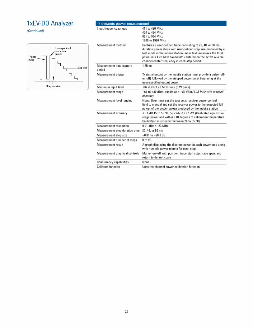
Tx dynamic power measurementInput frequency ranges 411 to 420 MHz
450 to 484 MHz821 to 934 MHz1700 to 1980 MHz
Measurement method Captures a user-defined trace consisting of 20, 40, or 80 ms duration power steps with user-defined step size produced by a test mode in the mobile station under test; measures the total power in a 1.23 MHz bandwidth centered on the active reverse channel center frequency in each step period
Measurement data capture period
1.25 ms
Measurement trigger Tx signal output by the mobile station must provide a pulse (off-on-off) followed by the stepped power burst beginning at the user-specified output power
Maximum input level +37 dBm/1.23 MHz peak (5 W peak) Measurement range −61 to +30 dBm, usable to < −69 dBm/1.23 MHz with reduced
accuracy Measurement level ranging None. User must set the test set’s receiver power control
field to manual and set the receiver power to the expected full power of the power sweep produced by the mobile station
Measurement accuracy < ±1 dB 15 to 55 °C, typically < ±0.5 dB. (Calibrated against av-erage power and within ±10 degrees of calibration temperature. Calibration must occur between 20 to 55 °C)
Measurement resolution 0.01 dBm/1.23 MHz Measurement step duration time 20, 40, or 80 ms Measurement step size −0.01 to −90.0 dB Measurement number of steps 0 to 99 Measurement result A graph displaying the discrete power at each power step along
with numeric power results for each step Measurement graphical controls Marker on/off with position, trace start step, trace span, and
return to default scale Concurrency capabilities None Calibrate function Uses the channel power calibration function

27
Fast Device Tune Measurement E1999A-202 FDT Enhanced
Fast device tune measurementInput frequency ranges 411 to 420 MHz
450 to 484 MHz821 to 934 MHz1700 to 1980 MHz
Measurement method Allows user definition of an RF source power output sequence simultaneously with a Tx power measurement sequence each consisting of 10 or 20 ms duration steps with user-defined step size. Sequence can be defined to repeat over a number of frequencies inside of a single frequency band. This measurement requires a test mode in the mobile station in order to operate. Measures the total power in a 1.23 MHz bandwidth centered on the active reverse channel center frequency in each step period
Measurement data capture period 0.313 μs Maximum input level +37 dBm/1.23 MHz peak (5 W peak) Measurement range −61 to +30 dBm, usable to < −69 dBm/1.23 MHz with
reduced accuracy Measurement capture range Mobile station’s transmit power must be within ±9 dB of the
expected power per the ranging configuration Measurement accuracy < ±1 dB 15 to 55 °C for the fast mode, typically < ±0.5 dB.
(Calibrated against average power and within ±10 degrees of calibration temperature. Calibration must occur between 20 to 55 °C)
Measurement resolution 0.01 dBm/1.23 MHz Measurement step duration (time) 10 or 20 ms Number of frequency steps 1 to 20 Number of amplitude steps 1 to 20 steps at each specified frequency Maximum steps in a sequence Up to 20 out of the possible 40 entries in each table MS Tx frequency step table 1 to 40 entries, with each value in MHz MS Tx power step table 1 to 40 entries, with each value in dBm MS Rx frequency step table 1 to 40 entries, with each value in MHz MS Rx power step table 1 to 40 entries, with each value in dBm MS Tx frequency step start index 0 to 39 MX Tx power step start index 0 to 39 MS Rx frequency step start index 0 to 39 MS Rx power step start index 0 to 39 RF generator settling time < 6.1 ms to be within ±0.1 dB of the final value RF generator modulation accuracy Typically < 3.1% RF generator level accuracy Same as listed under 1xEV-DO RF generator specifications Concurrency capabilities None Calibrate function Calibrates all measurement functions

28
Single Channel GPS SourceE1999A-206 single channel GPS source
Single channel GPS sourceGPS signal output RF IN/OUT or RF OUTPUT only GPS signal frequency 1.57542 GHz GPS signal output level range −70 to −125 dBm GPS signal output level accuracy < ±1.0 dB, −70 to −116 dBm
< ±1.5 dB, −116 to −125 dBm Code type Coarse/Acquisition (C/A) Chip Rate 1.023 Mcps Settable parameters Satellite ID, data patterns and filters

29
Timebase SpecificationsInternal high-stability 10 MHz oven-controlled crystal oscillator (OCXO)
Internal high stability 10 MHz oven-controlled crystal oscillator (OCXO)Aging rates < ±0.1 ppm per year, < ±0.005 ppm peak-to-peak per day during
any 24-hour period starting 24 hours or more after a cold start Temperature stability < ±0.01 ppm frequency variation from 25 °C over the
temperature range 0 to 55 °C Warm-up times 5 minutes to be within ±0.1 ppm of frequency at one hour,
15 minutes to be within ±0.01 ppm of frequency at one hour Accuracy After a 30-minute warm-up period of continuous operation is
derived from typically ±(time since last calibration) x (aging rate) + (temperature stability) + (accuracy of calibration)
Initial adjustment Typically ±0.03 ppm
External reference inputInput frequency 10 MHz Input frequency range Typically < ±5 ppm of nominal reference frequency Input level range Typically 0 to +13 dBm Input impedance Typically 50 Ω
External reference outputOutput frequency Same as timebase (internal 10 MHz OCXO or external reference
input) Output level Typically > 0.5 V rms Output impedance Typically 50 Ω
Trigger outputFrame clock output Selectable output of 1.67 ms, 26.67 ms, 426.67 ms, or 2 s
30
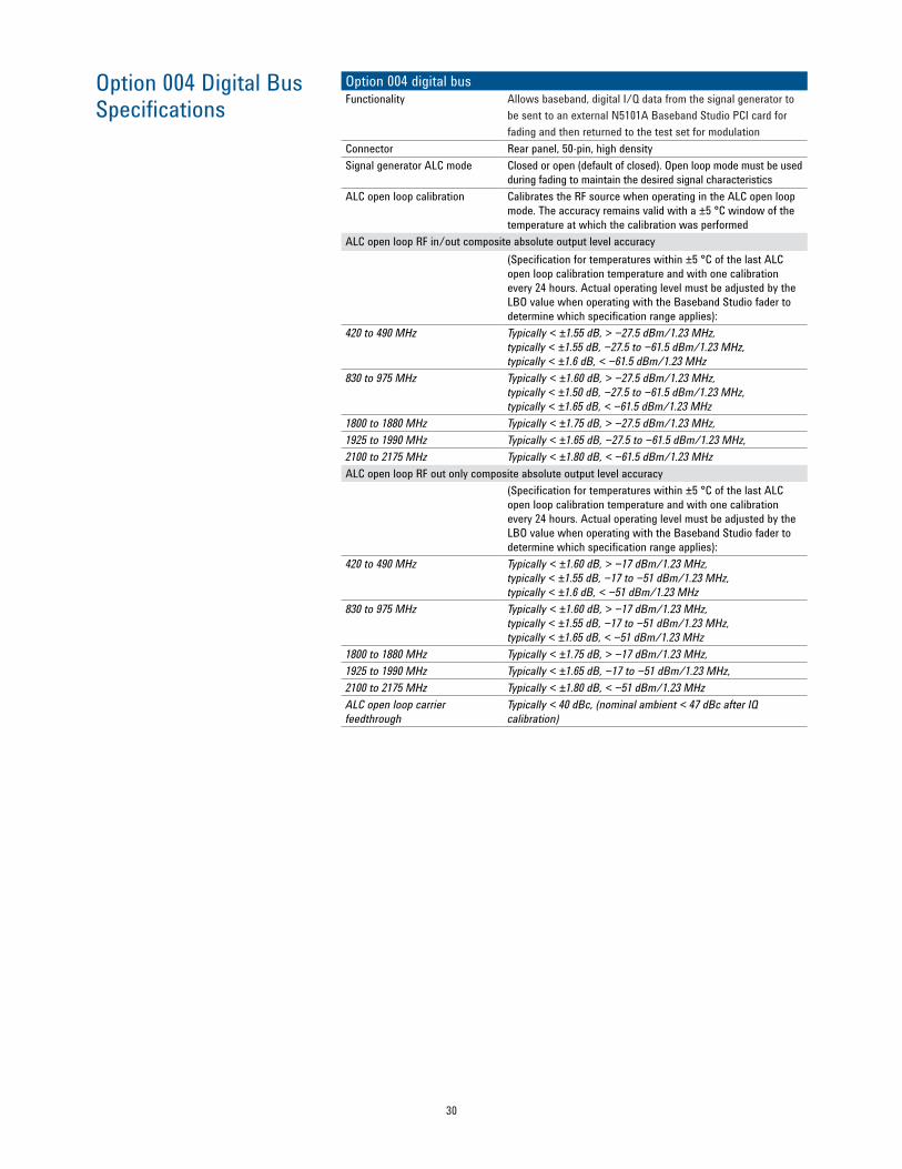
Option 004 Digital Bus Specifications
Option 004 digital busFunctionality Allows baseband, digital I/Q data from the signal generator to
be sent to an external N5101A Baseband Studio PCI card for fading and then returned to the test set for modulation
Connector Rear panel, 50-pin, high densitySignal generator ALC mode Closed or open (default of closed). Open loop mode must be used
during fading to maintain the desired signal characteristicsALC open loop calibration Calibrates the RF source when operating in the ALC open loop
mode. The accuracy remains valid with a ±5 °C window of thetemperature at which the calibration was performed
ALC open loop RF in/out composite absolute output level accuracy(Specification for temperatures within ±5 °C of the last ALCopen loop calibration temperature and with one calibration every 24 hours. Actual operating level must be adjusted by the LBO value when operating with the Baseband Studio fader todetermine which specification range applies):
420 to 490 MHz Typically < ±1.55 dB, > −27.5 dBm/1.23 MHz,typically < ±1.55 dB, −27.5 to −61.5 dBm/1.23 MHz,typically < ±1.6 dB, < −61.5 dBm/1.23 MHz
830 to 975 MHz Typically < ±1.60 dB, > −27.5 dBm/1.23 MHz,typically < ±1.50 dB, −27.5 to −61.5 dBm/1.23 MHz,typically < ±1.65 dB, < −61.5 dBm/1.23 MHz
1800 to 1880 MHz Typically < ±1.75 dB, > −27.5 dBm/1.23 MHz,1925 to 1990 MHz Typically < ±1.65 dB, −27.5 to −61.5 dBm/1.23 MHz,2100 to 2175 MHz Typically < ±1.80 dB, < −61.5 dBm/1.23 MHzALC open loop RF out only composite absolute output level accuracy
(Specification for temperatures within ±5 °C of the last ALCopen loop calibration temperature and with one calibration every 24 hours. Actual operating level must be adjusted by the LBO value when operating with the Baseband Studio fader todetermine which specification range applies):
420 to 490 MHz Typically < ±1.60 dB, > −17 dBm/1.23 MHz,typically < ±1.55 dB, −17 to −51 dBm/1.23 MHz,typically < ±1.6 dB, < −51 dBm/1.23 MHz
830 to 975 MHz Typically < ±1.60 dB, > −17 dBm/1.23 MHz,typically < ±1.55 dB, −17 to −51 dBm/1.23 MHz,typically < ±1.65 dB, < −51 dBm/1.23 MHz
1800 to 1880 MHz Typically < ±1.75 dB, > −17 dBm/1.23 MHz,1925 to 1990 MHz Typically < ±1.65 dB, −17 to −51 dBm/1.23 MHz,2100 to 2175 MHz Typically < ±1.80 dB, < −51 dBm/1.23 MHzALC open loop carrierfeedthrough
Typically < 40 dBc, (nominal ambient < 47 dBc after IQcalibration)

31
General Specifications Remote programmingGPIB IEEE Standard 488.2 Remote front panel lockout Allows remote user to disable the front panel display to
improve GPIB measurement speed Implemented functions T6, TE0, L4, LE0, SH1, AH1, RL1, SR1, PP0, DC1, DT0, C0, and E2
Save/recall registersStorage capacity Five registers that store the complete instrument state except
for active cell call processing status (fixed labels of register 1 to 5); registers are non-volatile
Recall Allows user to recall one of the five stored instrument states
Measurement speedMeasurement name One measurement Ten measurements Channel power (fast mode) 22 ms 157 ms Channel power (very fast mode) 9 ms 34 ms Average power 231 ms 2066 ms Waveform quality (PLO) 1 slot 270 ms 2425 ms Waveform quality (PLO) 8 slots 1752 ms 17088 ms Tx spurious response 303 ms 2299 ms Time response of open loop power 1141 ms NA

myAgilent
myAgilent
www.agilent.com/find/myagilentA personalized view into the information most relevant to you.
Three-Year Warranty
www.agilent.com/find/ThreeYearWarrantyBeyond product specification, changing the ownership experience. Agilent is the only test and measurement company that offers three-year warranty on all instruments, worldwide.
Agilent Assurance Plans
www.agilent.com/find/AssurancePlansFive years of protection and no budgetary surprises to ensure your instruments are operating to specifications and you can continually rely on accurate measurements.
www.agilent.com/quality
Agilent Electronic Measurement GroupDEKRA Certified ISO 9001:2008 Quality Management System
Agilent Channel Partners
www.agilent.com/find/channelpartnersGet the best of both worlds: Agilent’s measurement expertise and product breadth, combined with channel partner convenience.
www.agilent.comwww.agilent.com/find/E1966A
For more information on Agilent Technologies’ products, applications or services, please contact your local Agilent office. The complete list is available at:www.agilent.com/find/contactus
AmericasCanada (877) 894 4414 Brazil (11) 4197 3600Mexico 01800 5064 800 United States (800) 829 4444Asia PacificAustralia 1 800 629 485China 800 810 0189Hong Kong 800 938 693India 1 800 112 929Japan 0120 (421) 345Korea 080 769 0800Malaysia 1 800 888 848Singapore 1 800 375 8100Taiwan 0800 047 866Other AP Countries (65) 375 8100Europe & Middle EastBelgium 32 (0) 2 404 93 40 Denmark 45 45 80 12 15Finland 358 (0) 10 855 2100France 0825 010 700* *0.125 €/minuteGermany 49 (0) 7031 464 6333 Ireland 1890 924 204Israel 972-3-9288-504/544Italy 39 02 92 60 8484Netherlands 31 (0) 20 547 2111Spain 34 (91) 631 3300Sweden 0200-88 22 55United Kingdom 44 (0) 118 927 6201
For other unlisted countries:www.agilent.com/find/contactus(BP-01-15-14)
Product specifications and descriptions in this document subject to change without notice.
© Agilent Technologies, Inc. 2010 - 2014Published in USA,May 19, 20145990-5635EN
cdma2000 is a US registered certification mark of the Telecommunications Industry Association.