Embed Size (px)
Citation preview

__________________________________________________________________________________________________________________________________________
SAE Technical Standards Board Rules provide that: “This report is published by SAE to advance the state of technical and engineering sciences. The use of this report is entirely voluntary, and its applicability and suitability for any particular use, including any patent infringement arising therefrom, is the sole responsibility of the user.”
SAE reviews each technical report at least every five years at which time it may be reaffirmed, revised, or cancelled. SAE invites your written comments and suggestions.
Copyright © 2008 SAE International
All rights reserved. No part of this publication may be reproduced, stored in a retrieval system or transmitted, in any form or by any means, electronic, mechanical, photocopying, recording, or otherwise, without the prior written permission of SAE.
TO PLACE A DOCUMENT ORDER: Tel: 877-606-7323 (inside USA and Canada) Tel: 724-776-4970 (outside USA) Fax: 724-776-0790 Email: [email protected]
SAE WEB ADDRESS: http://www.sae.org
AEROSPACE STANDARD
AS5506/3
Issued 2011-04 Draft
SAE Architecture Analysis and Design Language (AADL) Annex Volume 3: Annex E: Error Model Annex
RATIONALE
The purpose of the Error Model Annex in this document is to enable modeling of different types of faults, fault behavior of individual system components, modeling of fault propagation affecting related components in terms of peer to peer interactions and deployment relationships between software components and their execution platform, modeling of aggregation of fault behavior and propagation in terms of the component hierarchy, as well as specification of fault tolerance strategies expected in the actual system architecture. The objective of the Error Model Annex is to support of qualitative and quantitative assessments of system dependability, i.e., reliability, availability, integrity (safety, security), and survivability, as well as compliance of the system to the specified fault tolerance strategies from an annotated architecture model of the embedded software, computer platform, and physical system.
This Architecture Analysis & Design Language (AADL) standard document was prepared by the SAE AS-2C Architecture Description Language Subcommittee, Embedded Computing Systems Committee, Aerospace Avionics Systems Division.

SAE AS5506/3 - 2 -
TABLE OF CONTENTS
1 REFERENCES ................................................................................................................................................................ 7
1.1 Normative References .............................................................................................................................................. 7
1.2 Informative References............................................................................................................................................. 7
ANNEX DOCUMENT E ERROR MODEL ............................................................................................................................ 8
Annex E.1 Scope ............................................................................................................................................................. 8
Annex E.2 Concepts and Terminology .......................................................................................................................... 10
Annex E.3 Error Model Libraries and Subclauses......................................................................................................... 12
Annex E.4 Error Types .................................................................................................................................................. 13
Annex E.5 Predeclared Error Types .............................................................................................................................. 15
Annex E.6 Error Propagation......................................................................................................................................... 17
E.6.1 Error Propagation and Contained Error Declarations ......................................................................................... 20
E.6.2 Error Flow Declarations ...................................................................................................................................... 20
E.6.3 Error Propagation Paths ..................................................................................................................................... 21
Annex E.7 Error Behavior State Machines .................................................................................................................... 22
E.7.1 Error and Repair Events ..................................................................................................................................... 25
E.7.2 Error Behavior States and Transitions ................................................................................................................ 26
Annex E.8 Component Error Behavior Specification .................................................................................................... 27
E.8.1 Handling of Incoming Propagated Errors ............................................................................................................ 29
E.8.2 Outgoing Propagated Errors ............................................................................................................................... 30
E.8.3 Error Propagation through Connections ............................................................................................................. 31
Annex E.9 Composite Error Behavior ........................................................................................................................... 31
Annex E.10 Error Models & Fault Management .......................................................................................................... 32
Annex E.11 Dual Redundant System Example ........................................................................................................... 32
Annex E.12 A Triple Redundant Network Example ..................................................................................................... 33
Annex E.13 A Large Example (Example from Error Model Annex V1) ....................................................................... 34
Annex E.14 Misc Material ............................................................................................................................................ 39

SAE AS5506/3 - 3 -

SAE AS5506/3 - 4 -
Foreword
(1) The AADL standard was prepared by the SAE Avionics Systems Division (ASD) Embedded Computing Systems Committee (AS-2) Architecture Description Language (AS-2C) subcommittee.
(2) This AADL standard defines x annexes to the SAE AADL standard AS5506A.
(3) This AADL standard includes an Error Model Annex that extends the AADL core language with a state machine-based sublanguage annex notation for specifying different types of faults, fault behavior of individual system components, fault propagation affecting related components in terms of peer to peer interactions and deployment relationship between software components and their execution platform, aggregation of fault behavior and propagation in terms of the component hierarchy, as well as fault tolerance strategies expected in the actual system architecture.
(4) The objective of the Error Model Annex is to support qualitative and quantitative assessments of system dependability, i.e., reliability, availability, integrity (safety, security), and survivability, as well as compliance of the system to the specified fault tolerance strategies from an annotated architecture model of the embedded software, computer platform, and physical system.

SAE AS5506/3 - 5 -
Introduction
(5) The SAE Architecture Analysis & Design Language (referred to in this document as AADL) is a textual and graphical language used to design and analyze the software and hardware architecture of performance-critical real-time systems. These are systems whose operation strongly depends on meeting non-functional system requirements such as reliability, availability, timing, responsiveness, throughput, safety, and security. AADL is used to describe the structure of such systems as an assembly of software components mapped onto an execution platform. It can be used to describe functional interfaces to components (such as data inputs and outputs) and performance-critical aspects of components (such as timing). AADL can also be used to describe how components interact, such as how data inputs and outputs are connected or how application software components are allocated to execution platform components. The language can also be used to describe the dynamic behavior of the runtime architecture by providing support to model operational modes and mode transitions. The language is designed to be extensible to accommodate analyses of the runtime architectures that the core language does not completely support. Extensions can take the form of new properties and analysis specific notations that can be associated with components and are standardized themselves.
(6) AADL was developed to meet the special needs of performance-critical real-time systems, including embedded real-time systems such as avionics, automotive electronics, or robotics systems. The language can describe important performance-critical aspects such as timing requirements, fault and error behaviors, time and space partitioning, and safety and certification properties. Such a description allows a system designer to perform analyses of the composed components and systems such as system schedulability, sizing analysis, and safety analysis. From these analyses, the designer can evaluate architectural tradeoffs and changes.
(7) AADL supports analysis of cross cutting impact of change in the architecture along multiple analysis dimensions in a consistent manner. Consistency is achieved through automatic generation of analysis models from the annotated architecture model. AADL is designed to be used with generation tools that support the automatic generation of the source code needed to integrate the system components and build a system executive from validated models. This architecture-centric approach to model-based engineering permits incremental validation and verification of system models against requirements and implementations against systems models throughout the development lifecycle.
(8) This document consists of x annexes to the SAE AADL standard that
• enables modeling of different types of faults, fault behavior of individual system components, modeling of fault propagation affecting related components in terms of peer to peer interactions and deployment relationships between software components and their execution platform, modeling of aggregation of fault behavior and propagation in terms of the component hierarchy, as well as specification of fault tolerance strategies expected in the actual system architecture. The objective of the Error Model Annex is to support of qualitative and quantitative assessments of system dependability, i.e., reliability, availability, integrity (safety, security), and survivability, as well as compliance of the system to the specified fault tolerance strategies from an annotated architecture model of the embedded software, computer platform, and physical system.

SAE AS5506/3 - 6 -
Information and Feedback
(9) The website at http://www.aadl.info is an information source regarding the SAE AADL standard. The website provides information and a download site for the Open Source AADL Tool Environment. It also provides links to other resources regarding the AADL standard and its use.
(10) The public AAD Wiki (https://wiki.sei.cmu.edu/aadl) maintains a list of AADL related publications by the community, and provides guidance on the use of extension of the open source OSATE tool set for AADL.
(11) Questions and inquiries regarding working versions of annexes and future versions of the standard can be addressed to [email protected].
(12) Informal comments on this standard may be sent via e-mail to [email protected]. If appropriate, the defect correction procedure will be initiated. Comments should use the following format:
!topic Title summarizing comment
!reference AADL-ss.ss(pp)
!from Author Name yy-mm-dd
!keywords keywords related to topic
!discussion
text of discussion
(13) where ss.ss is the section, clause or subclause number, pp is the paragraph or line number where applicable, and yy-mm-dd is the date the comment was sent. The date is optional, as is the !keywords line.
(14) Multiple comments per e-mail message are acceptable. Please use a descriptive “Subject” in your e-mail message.
(15) When correcting typographical errors or making minor wording suggestions, please put the correction directly as the topic of the comment; use square brackets [ ] to indicate text to be omitted and curly braces { } to indicate text to be added, and provide enough context to make the nature of the suggestion self-evident or put additional information in the body of the comment, for example:
!topic [c]{C}haracter
!topic it[']s meaning is not defined

SAE AS5506/3 - 7 -
1 References
1.1 Normative References
(1) The following normative documents contain provisions that, through reference in this text, constitute provisions of this standard.
(2) IEEE/ANSI 610.12-1990 [IEEE/ANSI 610.12-1990], IEEE Standard Glossary of Software Engineering Terminology.
(3) SAE AS-5506A:2009, Architecture Analysis & Design Language (AADL), Jan 2009.
(4) SAE AS-5506/1:2006, Architecture Analysis & Design Language (AADL) Annex Volume 1, June 2006.
(5) SAE ARP-4761 Guidelines and Methods for Conducting the Safety Assessment Process on Civil Airborne Systems and Equipment, December 1996.
(6) DO-178B Software Considerations in Airborne Systems and Equipment Certification, December 1992.
(7) DO-254 Design Assurance Guidance for Airborne Electronic Hardware, April 2000.
(8) MIL-HDBK-217F Reliability Prediction of Electronic Equipment, December 1991.
1.2 Informative References
(1) The following informative references contain background information about the items with the citation.
(2) [LAP 1992] Laprie, J.-C., editor, “Dependability: Basic Concepts and Terminology,” Dependable Computing and Fault Tolerance, volume 5, Springer-Verlag, Wien, New York, 1992. Prepared by IFIP Working Group 10.4 on Dependable Computing and Fault Tolerance.
(3) [IFIP WG10.4-1992] IFIP WG10.4 on Dependable Computing and Fault Tolerance, 1992, J.-C. Laprie, editor, “Dependability: Basic Concepts and Terminology,” Dependable Computing and Fault Tolerance, volume 5, Springer-Verlag, Wien, New York, 1992.
(4) [BNF 1960] Naur, Peter (ed.), "Revised Report on the Algorithmic Language ALGOL 60," Communications of the ACM, Vol. 3 No. 5, pp. 299-314, May 1960.

SAE AS5506/3 - 8 -
Annex Document E Error Model
Normative
Annex E.1 Scope
(1) The purpose of the Error Model Annex is to enable qualitative and quantitative assessments of system dependability, i.e., reliability, availability, integrity (safety, security), and survivability, as well as compliance of the system to specified fault tolerance strategies from an annotated architecture model of the embedded software, computer platform, and physical system.
(2) This annex defines a sublanguage that may be associated with components of an embedded system architecture expressed in core AADL through error annex clauses. The language features defined in this annex enable specification of fault types, fault behavior of individual components, fault propagation affecting related components, aggregation of fault behavior and propagation in terms of the component hierarchy, specification of fault tolerance strategies expected in the actual system architecture.
(3) The purpose of AADL is to model the computer based embedded system, including the runtime architecture of embedded systems. In that context the Error Model Annex defines a sublanguage that can be used to declare error models within an error annex library and associate them with components in an architecture specification.
(4) In this document we use the terms impairment, fault, failure, etc. according to its IFIP WG10.4 definition (see Section Annex E.2). For the description of the language constructs of the Error Model sublanguage and as keyword in the language we use the word error.
(5) The Error Annex sublanguage supports the declaration of collections of error types and their use in specifying error propagations. These error types are associated with interactions point of components (features such as ports as well as deployment bindings) to represent incoming and outgoing error propagations with related components. Users can also specify error types that are expected to not be propagated. For each component we can also specify an error flow, i.e., whether a component is the source or sink of an error propagation, or whether it passes on an incoming propagation as an outgoing propagation of the same or different error type (path).
Figure 1 Error Propagations and Error Propagation Flows
(6) The connection topology of the architecture as well as the deployment binding of software components to platform components determines which components are affected by outgoing error propagations of other components. This allows us to identify hazards and assess the impact of failures across interacting system components.

SAE AS5506/3 - 9 -
Figure 2 Error Propagation Paths Defined by Architecture
(7) The Error Annex sublanguage supports the specification of error behavior in terms of an error behavior state machine with a set of states and transitions that occur under specified conditions, as well as specification error and repair events that are local to a component. They are associated with components to specify how the error state of a component changes due to error events and error propagations as well as due to repair events. The error behavior specification also declares the conditions for an outgoing error propagation in terms of the component error behavior state and incoming error propagations. For example, the error state of a component might change due to an error event of the component itself, and/or due to an error propagated into that component from some other component. This allows us to characterize the error behavior of an individual component in terms it own failures, impact of other component failures on it, and whether it impacts other components.
(8) The Error Annex sublanguage supports the specification of a component’s composite error behavior as error states expressed in terms of the error states of its subcomponents. For example, a component having internal redundancy might be in an erroneous state only when two or more of its subcomponents are in an erroneous state. The resulting composite error behavior of the component must be consistent with an abstracted error behavior specification expressed by an error behavior state machine. This allows us to model error behavior at different levels of architectural abstraction and fidelity and keep these specifications consistent.
(9) The Error Annex sublanguage supports the specification of the impact of errors propagating from the components involved in performing a transfer specified by a connection on the communicated information.
(10) Finally, the Error Annex sublanguage supports the specification of how components detect and mitigate errors in their subcomponents or the components on which they depend through redundancy and voting. In addition constructs are provided to link the specified error behavior with the health monitoring and management elements of a system architecture and its behavior expressed in core AADL and the AADL Behavior Annex published in SAE AS5506-2.
(11) The language features defined in this annex can be used to specify the risk mitigation methods employed in embedded computer system architectures to increase reliability, availability, integrity (safety, security), and survivability. The error behavior of a complete system emerges from the interactions between the individual component error behavior models. This annex defines the overall system error behavior as a composition of the error models of its components, where the composition depends on the structure and properties of the architecture specification. More formally, a component error model is a stochastic automaton, and the rules for composing component stochastic automata error models to form a system error model depend on the potential error propagations and error management behaviors declared in the architecture specification.
(12) The Error Model Annex can be used to annotate the AADL model of an embedded system to support a number of the methods cited in SAE ARP4761, “Guidelines and Methods for Conducting the Safety Assessment Process on Civil Airborne Systems and Equipment.” An architecture specification with error annex annotations may be subjected to a variety of analysis methods ranging from Functional Hazard Assessment (FHA), Failure Mode and Effect Analysis (FMEA), Common Cause Analysis (CCA) and Fault Tree Analysis (FTA) to stochastic reliability and

SAE AS5506/3 - 10 -
availability analysis. For example, fault trees can be generated from such specifications to assess safety; stochastic process models (Markov or Stochastic Petri nets) can be generated to assess reliability and availability.
(13) From the bottom-up, the error models of low-level components typically capture the results of failure modes and effects analysis (e.g. as failure modes and effects analysis is defined in SAE ARP 4761). From the top-down, the error models of the overall system and high-level subsystems typically capture the results of system hazard analysis (e.g. as hazard analysis is defined in SAE ARP 4761). The rules defined in this annex assure that the results of these analyses as captured in an architecture specification are consistent and complete with respect to each other. For example, this enables an integrated approach that insures consistency and completeness between hazard analysis, failure modes and effects analysis, and the safety and reliability analyses that relate the two.
(14) This annex supports a compositional approach to modeling different dependability concerns. This enables reuse of error models and leverages reuse of component specifications in core AADL. Modifications to architecture specifications are propagated into safety and reliability models by automatically regenerating them. Architectural abstraction and composite error behavior specifications support mixed-fidelity modeling, and enable improved traceability and consistency between architecture specifications and models and analysis results.
(15) The Error Model Annex definition is organized into the following sections. Section Annex E.2 introduces concepts and terminology used in this annex document. Section Annex E.3 describes the two major groups of Error Model Annex language constructs, reusable Error Model libraries, and component-specific Error Model subclauses. Section Annex E.4 introduces constructs to define a hierarchy of error types. Section Annex E.5 describes a set of predeclared error types. Section Annex E.6 introduces constructs in support of error propagation specification. Section Annex E.7 introduces constructs to define reusable error behavior state machines with error and repair events, states, and transitions. Section Annex E.8 describes constructs to support specification of error behavior of components in terms of an error behavior state machine, transition trigger conditions in terms of incoming error propagations, conditions for outgoing error propagation in terms of error behavior states and incoming error propagations, and error detection events. Section Annex E.9 describes constructs to support specification of composite error behavior of components based on the error state behavior of a set of subcomponents. Section Annex E.10 discusses the interaction between the error behavior specification expressed by Error Model Annex constructs and the health monitoring and fault management capabilities in the actual system architecture. The document closes with several examples of system architecture models annotated with Error Model Annex specifications.
Annex E.2 Concepts and Terminology
(1) The definitions of this section are based on the concepts and terminology defined by IFIP Working Group 10.4 on Reliable Computing and Fault Tolerance, and the IEEE Computing Society Technical Committee on Fault Tolerant Computing [IFIP WG10.4-1992]. They address impairment to system and component functionality and means of mitigating the impairment. The terms fault, error, failure, and latency of a fault or error are those of [IFIP WG10.4-1992].
(2) The terms fault, fault latency, error, error latency, failure, and error propagation have the same meaning as defined in Section 1.4 of AS5506A, but are restated here in words that relate somewhat more clearly to other terms used in this annex.
(3) A fault is an anomalous undesired change in the structure or data within a component that may cause that component to eventually fail to perform according to its nominal specification. Examples of faults overheating of hardware circuits, or programmers making coding mistakes when producing source text. Faults are the phenomenological cause of a failure. Failures and errors are effects of a fault.
(4) An error is part of a system or component state that differs from that under nominal behavior. The activation of a fault places a component into such an error state (possibly after some delay called the fault latency). An erroneous component may persist in that error state for some period of time before it behaves in a way that violates its nominal specification (called the error latency). For example, a burned out transistor (an activated fault) in an adder circuit does not cause a processor to violate its nominal specification until that circuit is used (after a fault latency) and produces an incorrect output value (erroneous state information).
(5) A failure occurs when a component deviates from its nominal (service) behavior specification as a consequence of an error. The deviation, i.e., the failure, can be characterized by type, persistence, and degree of severity. The degree to which a failure affects nominal behavior is referred to as criticality of the failure.

SAE AS5506/3 - 11 -
(6) This error behavior of a component is specified through an error behavior state machine that consists of states and transitions. The states of this error behavior state machine can represent both error-free (working) states and error (non-working) states. Fault activation is represented as an error event. An error event can cause a change in the error behavior state of a component.
(7) This component failure may affect the nominal behavior other components that the failed component interacts with. We refer to this as error propagation (also called fault propagation) out of the component to related component. This may occur with some error latency after the component first enters an erroneous state. For example, an erroneous component may send an incorrect value in a message or exceed its specified worst-case execution time.
(8) Error propagation is represented in an Error Model specification by specifying outgoing and incoming error propagations for each of the component features and for component bindings to the computer platform. The error propagation path from an outgoing error to an incoming error is determined by the core AADL model through the connections between the respective features and the binding declarations. A component can be an error propagation source, sink, or pass on a propagated error as the same of different type. This role is specified by a error propagation flow, which allows for fault impact analysis without needing to know the internal error behavior of a component.
(9) A propagated error may place the receiving components into error states, exactly like an error event. The components receiving the propagated error need not fail if they are tolerant to errors. In other words, incoming error propagations can be part of a transition trigger condition. Impacted components may remain in a non-working state even though the original component may have returned to a workings state.
(10) A component may also encounter a repair action. For example, the effects of a transient fault may disappear after some interval of time, or a failed component may be replaced. A repair action restores a component to an error-free state. This is expressed in an Error Model specification through repair events that are part of a transition trigger condition in the error behavior state machine.
(11) System components may be composed of subcomponents. The error behavior of the subcomponents affects the error behavior of the enclosing component. For example, a system component with internal redundancy may enter a non-working state if both is its redundant subcomponents are in a non-working state. Similarly, a subcomponent may propagate an error to components outside the enclosing component if it interacts with those components via the enclosing component interface. The Error Model Annex supports a compositional approach to specifying such error behavior. A component may be annotated with an error behavior state machine that characterizes its error behavior abstractly, i.e., independent of whether it contains subcomponents. Separately, the modeler can specify a composite error behavior in terms of subcomponent error behavior, which must be consistent with the abstract error behavior specification.
(12) In the terminology of a failure modes and effects analysis, an error state is a failure mode that, if associated with an outgoing propagated error, can affect other components. A failure effect is resulting error state of a component due to an incoming propagated error. The relationship between the failure mode and the failure effect is determined by the connection between the components or by the deployment binding.
(13) It is common practice to assume that the risk due to generic or design errors introduced by development-time faults (also known as design defects or bugs) has been reduced to an acceptable level prior to the start of system operation through the use of appropriate design assurance methods. For example, RTCA DO-178B and RTCA DO-254 provide guidelines for assuring that fielded avionics software code and hardware circuits have acceptably low risk of consequential design errors. For mechanical components the error behavior specified by the Error Model Annex primarily reflects physical failure of the component in use. In the case of software the error behavior specification reflects the activation of design and coding errors and their impact on the system. In other words, a error event corresponds to a run-time flow of control and data that reveals a design defect (introduced a run-time error due to a design defect), rather than to the development-time introduction of that design defect.
(14) There are many means of mitigating impairment of systems or components. Fault avoidance is to apply techniques that focus on not introducing faults or eliminating them before the system goes into operation. Fault tolerance focuses on fault detection, fault isolation, and fault recovery. Fault recovery elements include fault containment, fault masking, fault repair, and fault correction. The Error Model Annex supports specification of faults that are expected to be avoided, masked, propagated, detected, and recovered from. Fault tolerance support in the actual system is modeled through the AADL language and the Behavior Annex.

SAE AS5506/3 - 12 -
Annex E.3 Error Model Libraries and Subclauses
(1) Error Model libraries contain reusable declarations, such as sets of error types and error behavior state machine specifications that include error and repair events. Error Model libraries are declared in packages. Those reusable declarations can be referenced in annex subclauses by qualifying them with the package name.
(2) Error Model subclauses allow component types and component implementations to be annotated with Error Model specifications. Those component-specific Error Model specifications define incoming and outgoing propagated errors for features, error flows from incoming to outgoing features. They also specify component error behavior in terms of an error behavior state machine augmented with transition conditions based on incoming propagated errors, conditions for outgoing propagation, and event signaling the detection of errors in the system architecture. Finally, they specify the composite error behavior of a component in terms of the error behaviors of its subcomponents.
Syntax
error_model_subclause ::=
annex Error_Model (
( {** error_model_constructs **} )
| none )
[ in_modes ] ;
error_model_library ::=
annex Error_Model (
( {** error_model_reusable_constructs **} )
| none ) ;
error_model_reusable_constructs ::=
( error_type_set | error_behavior_state_machine )+
error_model_constructs ::=
( error_propagations | error_behavior | composite_error_behavior
)+
Naming Rules
(N1) The mode identifiers in the in_modes statement must refer to modes in the component type or component
implementation for which the annex subclause is declared.
Legality Rules
(L1) Annex subclauses can only be declared in component types and component implementations.
Semantics
(3) An Error Model library provides reusable specifications of sets of error types and of error behavior specifications expressed through error behavior state machines. Those reusable declarations can be referenced by annex subclauses by qualifying them with the package name.
(4) An Error Model subclause allows component types and component implementations to be annotated with error events to represent activation of component fault activations, repair events to represent initiation and completion of a repair activity, incoming and outgoing propagation of errors through component features as well as through

SAE AS5506/3 - 13 -
bindings to platform components, error behavior of the component expressed as a state machine in terms of its fault and repair events and incoming error propagations as well as resulting in outgoing error propagations, error behavior of a component as a composite of the error behavior of its subcomponents, and a mapping between the error behavior expressed in the Error Model specification and the behavior of the fault/health management portion of the embedded system architecture expressed in core AADL and the Behavior Annex specifications.
(5) Error Model subclauses can be declared to be applicable to specific modes by specifying them with an in_modes
statement. An Error Model subclause without an in_modes statement contains Error Model statements that are
applicable in all modes. This capability allows users to attach mode specific Error Model annotations to core AADL models.
Discussion: We need to make sure that we explain which constructs can be mode specific and what it means when the system transitions from one mode to the next, e.g., what it means in terms of the current state of the error state machine.
Annex E.4 Error Types
(1) In this section we introduce the concept of error types. An error type identifies the type of fault being activated, the type of error being propagated, or the type of error state of a system or component.
(2) Error types can be organized into a type hierarchy. Error subtypes are acceptable substitutes for error types. Error types can be defined to have alias names that better reflect the application domain. The error type and its alias are considered to be equivalent.
(3) Error type declarations are grouped into error type sets. An error type set provides a name scope for error types. Error types are uniquely identified by their name in the context of an error type set. Error type sets can be defined as extensions of existing error type sets, adding new error types and placing them into the error type hierarchy.
(4) Predeclared sets of error types have been defined with the Error Model Annex standard. They can be extended with user defined error types or renamed with aliases.
Syntax
error_type_set ::=
basic_error_type_set | error_type_set_extension | error_type_set_alias
basic_error_type_set ::=
error type set defining_error_type_set_identifier
{ error_type | error_type_alias }+
end defining_error_type_set_identifier ;
error_type_set_extension ::=
error type set defining_error_types_identifier
extends qualified_error_type_set_reference
{ error_type | error_type_alias }+
end defining_error_type_set_identifier ;
error_type_set_alias ::=
error type set defining_error_types_identifier
renames qualified_error_type_set_reference
{ error_type | error_type_alias }+

SAE AS5506/3 - 14 -
end defining_error_type_set_identifier ;
error_type ::=
error type defining_error_type_identifier
[ extends qualified_error_type_reference ]
[ { { error_property_association }+ } ] ;
error_type_alias ::=
error type defining_error_type_identifier renames qualified_error_type_reference ;
qualified_error_type_reference ::=
( error_type_set_or_alias_identifier . )? error_type_identifier
qualified_error_type_set_reference ::=
[ package_identifier :: ] error_type_set_identifier
Naming Rules
(N1) The defining identifier of an error type set must be unique within the name scope of the package that contains the Error Model library declaration defining the error type set.
(N2) The defining identifier of an error type must be unique within the name scope of the error type set that contains the defining error type declaration.
(N3) An error type set that is an extension of another error type set inherits the namespace of the error type set being extended. In other words, an error type identifier must be unique with respect to the locally declared error types as well as those inherited through the extension.
(N4) The reference to an error type set must be qualified with the name of the package that contains the declaration of the error type set being referenced unless the error type set is located in the same package.
(N5) The package name of a qualified error type set reference must be named in the with clause of the enclosing package.
(N6) An error type set may be declared as a new namespace for aliases to an existing error type set. While the error type aliases are declared in terms of error types of the error type set identified by the renames clause, only the alias identifiers and newly defined error types are part of this error type set.
(N7) The reference to an error type must be qualified with the error type set identifier, unless the referenced error type exists in the error type set containing the reference. The error type set identifier used in the qualification does not itself have to be qualified with a package name, since it has been introduced as an alias by the renames or extends clause for the error type set.
(N8) If an error type declaration in an aliased error type set extends another error type, then that error type reference must be to an error type or alias within the aliased error type set.
Legality Rules
(L2) An error type set can contain more than one root error type, i.e., an error type that is not a subtype of another error type.
(L3) An error type cannot be the subtype of more than one other error type. This is enforced syntactically.

SAE AS5506/3 - 15 -
(L4) An error type set cannot be the extension of more than one error type set. This is enforced syntactically.
(L5) The property associations declared for an error type must only associate properties that apply to error types.
Semantics
(5) An error type set introduces a name scope for a set of error types. Error types are uniquely identified by their name within the context of an error type set.
(6) An error type set can be declared as an extension of another error type set. It inherits all the error type declarations from that error type set. This allows an error type hierarchy to be extended.
(7) An error type may be declared as a subtype of another error type. This establishes a single inheritance error type hierarchy. For example, the error type ValueError has two subtypes BadValue and OutOfRange.
(8) An error subtype is considered to be an acceptable substitute for an error type. For example, an outgoing error propagation of error type BadValue is acceptable for an error propagation path to an incoming error propagation of error type BadValue.
(9) An error type may be declared as an alias (renames) of another error type. The two error types are considered to be equivalent with respect to the type hierarchy. The renames clause allows domain specific names to be introduced without extending the type hierarchy. For example, the alias NoPower may be a more meaningful name for the error type Omission in the context of hardware.
(10) An error type set can be declared as an aliased error type set that introduces a new namespace for aliases. In this case the error types of the original error type set are not inherited into the namespace of the aliased error type set. This allows the names of error types in an error type hierarchy to be mapped into more names more meaningful in the context of specific component categories and component types without making the original error type names visible.
(11) An error type set may contain more than one error type hierarchies.
(12) An error type may have properties that characterize it.
Annex E.5 Predeclared Error Types
(1) The set of predeclared errors provides a common starting point for an error type hierarchy. It contains error types related to platform components as physical resources to software components, related to platform components as physical/mechanical components, and related to software components.
(2) These error types may reflect faults of a component that can be activated (error events). For example, a deadline miss by a periodic thread may manifest itself as an omission that can be observed by the recipient of component output.
(3) These error types may reflect the type of error being propagated between components. In the case of software components that operate in a fault container (process with runtime enforced address space protection, or partition with both space and time partition enforcement), the error propagation is limited to propagation paths along explicit interaction channels (port connections, shared data access, subprogram service calls) and execution platform bindings. This allows us to map a large number of software component faults into a limited number of fault propagation error types. For example, a divide by zero in an arithmetic expression or a deadline miss by a periodic thread may manifest itself as an omission of output that can be observed by the recipient of component output.
(4) Various safety analyses, e.g., HAZOP and SHARD, have developed a set of guide words to help identify hazards to be addressed. The following error types have been identified with respect to the presence or absence of service/data (Service Error), the content/value of the service (Value Error), the time-sensitive nature of the service/data (Timing Error), the fact that the service/data is provided as a sequence over time (Sequence Error).
• Service error: Omission (no service/data when service is expected), Commission (service/data when no service is expected)

SAE AS5506/3 - 16 -
• Value error: Bad value (subtle error due to incorrect or imprecise value), Out of range (coarse error due to inconsistent or out of tolerance values)
• Timing error: Early (early arrival of data or command), Late (late arrival of data or command)
• Sequence error: Bad rate (dropped element, stuck value, old data, low/high rate, rate variation), Out of order (wrong command sequence).
error type set Errors
error type Error;
error type ServiceError extends Error;
error type Omission extends ServiceError;
error type Commission extends ServiceError;
error type TimingError extends Error ;
error type Early extends TimingError ;
error type Late extends TimingError ;
error type ValueError extends Error ;
error type Badvalue extends ValueError ;
error type OutOfRange extends ValueError ;
error type SequenceError extends Error ;
error type BadRate extends SequenceError ;
error type OufOfOrder extends SequenceError ;
end Errors;
(5) These abstract error types can be refined both in terms of providing more meaningful domain specific names, and by introducing sub-categories of error types.
(6) For port-based communication between software components we may refine some of these error types. See Examples below.
(7) For processors as resource to execute threads we may refine the propagation error types as shown in Examples below.
Examples
-- This is an example is extending an existing error type with an additional subtype
error type set MyErrors extends ErrorTypes::Errors
error type Jitter extends TimingError ;
end MyErrors;
-- This example defines error types for use error propagation through ports
-- The namespace includes both the original error type names and the local ones
error type set PortErrors extends ErrorTypes::Errors
error type NoData renames Omission ;
error type ExtraData renames Commission ;
error type WrongValue extends BadValue;
error type EstimatedValue extends BadValue;
end PortErrors;
-- This example defines error types for use error propagation from processors

SAE AS5506/3 - 17 -
-- Only the error type names declared in this error type set are part of the namescope
error type set ProcessorErrors use ErrorTypes::Errors
error type NoResource renames Omission ;
error type NoDispatch extends NoResource;
error type NoCycles extends NoResource;
error type UnexpectedDispatch renames Commission ;
error type MissedDeadline renames Late ;
error type BadDispatchRate renames BadRate ;
error type DispatchJitter extends BadDispatchRate;
error type WrongDispatchRate extends BadDispatchRate;
end ProcessorErrors;
Annex E.6 Error Propagation
(1) In this section we introduce the concept of error propagation. Error propagation occurs when a component fails and the failure can be observed by other components, i.e., an error is propagated from one component to another.
(2) For each component we specify the types of errors that are propagated through its features and bindings or are not to be propagated by the component. We also specify the role of the component in the flow of error propagations, i.e., whether it is the error source, error sink, or error path from incoming propagations to outgoing propagations. The propagation paths between components are determined by the core AADL model, i.e., they follow interactions between components through their features and along software to hardware component binding relations.
Syntax
error_propagations ::=
error propagations
( import_error_type_set )*
{ error_propagation | contained_error }+
( flows
{ error_flow }+
)?
end ;
import_error_type_set ::=
[ defining_alias_identifier ] renames qualified_error_type_set_reference ;
error_propagation ::=
qualified_error_type_reference : [ in | out ] propagation
applies to feature_reference | binding_reference
[ { { error_property_association }+ } ] ;
contained_error ::=
qualified_error_type_reference : not [ in | out ] propagation

SAE AS5506/3 - 18 -
applies to feature_reference | binding_reference
[ { { error_propagation_property_association }+ } ] ;
feature_reference ::=
feature_identifier | access
binding_reference ::=
processor | memory | bus | device | virtual bus | virtual processor
| binding | bindings
error_flow ::=
error_source | error_sink | error_path
error_source ::=
error source error_propagation_reference : [ fault_source ]
[ { { error_flow_property_association }+ } ] ;
error_sink ::=
error sink error_propagation_reference
[ { { error_flow_property_association }+ } ] ;
error_path ::=
error path error_propagation_reference -> error_propagation_reference
[ { { error_flow_property_association }+ } ] ;
error_propagation_reference ::=
feature_reference [ qualified_error_type_reference ]
| binding_reference [ qualified_error_type_reference ]
Discussion: the optional fault source in the error source declaration allows the modeler to indicate which type of fault activation (error event) results in the propagated error. This would mean that the error events would need to be visible as part of the “external error propagation view” of the Error Model specification.
Naming Rules
(N1) The package name of a qualified error type set reference must be named in the with clause of the enclosing package.
(N2) If the error type set reference does not include a package name, then the referenced error type set must be declared in the same package as the reference.
(N3) The renames clause introduces the error type set identifier as alias. If two error type sets with the same name are made accessible, then at least one of the renames must introduce an explicit alias identifier that is different from any conflicting error type set identifiers.

SAE AS5506/3 - 19 -
(N4) The renames clause makes the error types contained in the referenced error type set visible to the error propagations clause. If an error type identifier is contained in more than one referenced error type set, then references to the error type must be qualified by the error type set identifier or alias.
(N5) The error type identifier in a error propagation declaration, contained error declaration or error flow declaration must exist in the namespace of one of the error type sets listed in the renames clauses.
(N6) An error type must not be referenced in both an error propagation declaration and a contained error declaration for the same feature or binding reference.
(N7) The feature identifier in a error propagation declaration, contained error declaration or error flow declaration must exist in the namespace of the component type or implementation that contains the error propagations clause.
(N8) The qualified error type reference in an error flow declaration must refer to an error type identified in the error propagation declaration for the same feature or binding reference.
Legality Rules
(L6) The binding reference of error propagations and error flows for software components must only contain processor, memory, bus, device, virtual bus, virtual processor.
(L7) The binding reference of error propagations and error flows for processor, memory, bus, and device components must only contain bindings.
(L8) The binding reference of error propagations and error flows for virtual bus, virtual processor, and system components may include processor, memory, bus, device, virtual bus, virtual processor, binding, and bindings.
(L9) The direction of the error propagation must be consistent with the direction of the feature being referenced. For an incoming propagated error the feature must support incoming information flow. For an outgoing propagated error the feature must support outgoing information flow. If the propagated error declaration does not indicate a direction the direction of the feature determines the direction of the propagated error.
The following matching rules apply to error propagations on the source and destination of error propagation paths between components:
(L10) The error type of the outgoing error propagation must be the same type or a subtype of the destination error type. Error types and error type aliases are considered to be the same.
(L11) The direction of the error propagation or contained error for the source must be outgoing and for the destination must be incoming.
(L12) For a contained error of a destination the source must have a contained error of the same type.
(L13) For an error propagation of a destination the source must have a contained error or error propagation or missing error propagation or contained error declaration.
(L14) For a missing error propagation or contained error declaration of a destination the source must have a contained error of the same type.
Consistency Rules
(C1) Every error type in a type hierarchy must be covered by error propagation or contained error declarations for a feature or binding.
(C2) All error types referenced in error propagation or contained error declarations for the same feature must be part of the same error type hierarchy.

SAE AS5506/3 - 20 -
Semantics
(3) An error propagations annex subclause consists of error propagation and contained error declarations for each of the features and the bindings of components as well as error flow declarations that indicate the role of the component in error propagations. These declarations for each component are combined with error propagation paths between instances of the components to determine an error propagation flow graph for a system architecture instance.
(4) The renames clause makes the name scope of an error type set accessible to error propagation, contained error, and error flow declarations. Those declarations can reference the error type by name without further qualification. When multiple error type sets are identified through renames clauses in the same error propagations subclause, error types with the same name may exist in more than one error type set. In this case, references to such an error type must be qualified by the error type set identifier or alias introduced as part of the renames clause.
E.6.1 Error Propagation and Contained Error Declarations
(5) An error propagation declaration specifies that errors of the named type are propagated into or out of a component through the feature or binding to which it is applied.
(6) Features may have incoming information flow, e.g., in ports and read-only data access, outgoing information flow, e.g., out ports and write-only data access, or bi-directional information flow, e.g., in out ports and read-write data access. Error propagations follow the same flow direction. Error propagation may occur along bus access connections.
Discussion: subprogram call and error propagation needs to be addressed.
(7) An error propagation declaration indicating direction in specifies expected incoming errors, direction out specifies intended outgoing errors, and without direction indicator specifies propagation of the particular error type in both directions. A bi-directional feature can have different incoming and outgoing error types being propagated by separately declaring the incoming and the outgoing error type for the feature.
(8) In the case of data or bus access connections the data component or bus component may be the source of a connection. In this case, the keyword access is used to identify the access point since no named access feature is specified.
(9) Errors can propagate between software components and execution platform components they are bound to. The keywords processor, bus, virtual processor, virtual bus, memory, and device are used to identify the binding point of a software component with the execution platform component it is bound to. The keyword binding is used for connections and virtual buses to identify their binding to execution platform components. Similarly, the keyword bindings is used in execution platform components to identify the binding point of components bound to them.
(10) Contained error declarations allow the modeler to explicitly specify, which error types are expected not to be propagated. When declared for an outgoing feature (or binding) it is an indication that the component intends to mask the error if it occurs. When declared for an incoming feature it is an indication that the component does not expect an error of this type to be propagated to it.
(11) The purpose of contained error declarations is to complement the error propagation declarations, such that a modeler can provide a complete record of the types of errors explicitly being addressed by the Error Model annotation for a component. This allows a consistency checking tool to determine whether an error of a given type is not intended to be propagated or whether the Error Model specification is incomplete and unspecified error types may be propagated.
(12) Error propagation and contained error declarations on outgoing features and bindings must be consistent with those of incoming features of the target of an error propagation path. See (L10) through (L14) and (C1) through (C2) of Section Annex E.6 for details of this consistency.
E.6.2 Error Flow Declarations
(13) Error flows are intended to be an abstraction of the error flow represented by component error behavior specifications in terms of error behavior state machines, error and repair events, and conditions under which

SAE AS5506/3 - 21 -
transitions and outgoing propagations are initiated. The error flows of a component must be consistent with its component error behavior specification.
(14) By default a component is the source of all its outgoing error propagations and all incoming error propagations can potentially result in outgoing error propagations on all of its outgoing features or bindings.
(15) The purpose of error flow declarations is to indicate the role of a component in the propagation of errors in terms of being an error propagation source (error source), an error propagation sink (error sink), to pass-through incoming error propagations as outgoing errors of the same type, or to transform an incoming error of one type into an outgoing error of a different type (error path).
(16) The type of an outgoing error propagation of a component feature or binding can be an error flow source as well as the destination of an error flow path. The type of an incoming error propagation of a component feature or binding can be an error flow sink, while the same error type may be propagated out due to an error flow source or due to an error flow path specification with a different incoming error propagation from the same component feature or an error flow path from a different feature or binding.
E.6.3 Error Propagation Paths
(17) Error propagation paths represent the flow of error propagations between components. Error propagation paths are determined by the connections between components, both application components and platform components, as well as by the binding of application components to platform components.
(18) The following rules define possible propagations from a component or connection to other components and connections and mode transitions in an architecture. Propagations may occur from
• a processor to every thread bound to that processor (and the other direction?)
• a processor to every virtual processor bound to that processor
• a processor to every connection bound to that processor
• a virtual processor to every virtual processor bound to that virtual processor
• a virtual processor to every thread bound to that virtual processor
• a virtual processor to every connection bound to that virtual processor
• a memory to every software component bound to that memory
• a memory to every connection bound to that memory
• a bus to every connection bound to that bus
• a bus to every virtual bus bound to that bus
• a virtual bus to every connection bound to that virtual bus
• a device to every connection bound to that device
• a component to each of its required and provided subcomponents
• a component to everything that requires or provides it
• a component to every connection from any of its outgoing features
• a connection to every component having an incoming feature to which it connects
• a client subprogram to every server subprogram to which a call is bound
• a server subprogram to every client whose calls are bound to that server
• a subcomponent to every other subcomponent of the same process
• a process to every other process that is bound to any common processor or memory, except for processes that are partitioned from each other on all common resources

SAE AS5506/3 - 22 -
• a connection to every other connection that is routed through any common bus, processor or memory, except for connections that are partitioned from each other on all common resources
• an event connection to every mode transition that is labeled with an in event port that is a destination of that connection.
Properties
(19) Error propagation and error flow declarations can have property associations. These properties further characterize the propagated error in support of different safety and reliability analyses.
(20) An occurrence property indicates the probability with which the error is being propagated.
Discussion: Some people distinguish between occurrence rate (x per time unit), occurrence probability, and occurrence probability distribution. In V1 we specified a probability value and distribution.
(21) A severity property indicates the severity of the hazard represented by the propagated error, e.g., in the context of a Functional Hazard Assessment (FHA) [DO-178B].
(22) A likelihood property indicates the likelihood with which the hazard occurs [DO-178B].
(23) A description property provides a way of textually describing the hazard.
(24) A risk property provides a way of textually describing the potential risk of the hazard.
(25) The occurrence property can be associated with an outgoing error propagation. In this case it represents to probability with which the propagation occurs.
Discussion: What could be the meaning of an occurrence probability associated with an incoming error propagation?
(26) When associated with an error flow the occurrence property represents the probability with which an outgoing error propagation occurs based on the given flow. For example, the outgoing error propagation BadData may originate from within the component based on the occurrence probability of the error source declaration, and may pass on an incoming error propagation with a different probability. In the latter case, the occurrence probability may be inferred from the originator of the incoming error propagation.
Discussion: Some of these properties can be associated with the error type and thus inherited by the propagated error declarations.
Discussion: If the risk occurs in an operational phase we can utilize AADL modes to represent the phases and specify mode specific property values.
Examples
(27) <example of use for FHA. Use of outgoing error propagations to specify hazards to be considered in an FHA.
(28) <example of use for FMEA. Use of error events as representing activated faults (failure mode), error propagations to represent the first level effects, and progression through error propagation paths and flows to determine higher level effects. <add figure with an example from Hecht or SAVI Phase 2>
(29) <Example of use for fault impact analysis
Annex E.7 Error Behavior State Machines
(1) In this section we introduce the concept of an error behavior state machine. An error behavior state machine consists of a set of states and transitions between the states. The trigger conditions for the transitions are expressed in terms of error events and repair events and in terms of incoming propagated errors. The resulting state can affect outgoing error propagations.
(2) An error behavior state machine can be defined as an extension of another error behavior state machine. The elements of the error behavior state machine being extended are inherited into the extension.
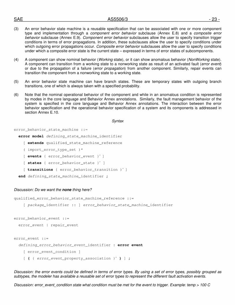
SAE AS5506/3 - 23 -
(3) An error behavior state machine is a reusable specification that can be associated with one or more component type and implementation through a component error behavior subclause (Annex E.8) and a composite error behavior subclause (Annex E.9). Component error behavior subclauses allow the user to specify transition trigger conditions in terms of error propagations. In addition, these subclauses allow the user to specify conditions under which outgoing error propagations occur. Composite error behavior subclauses allow the user to specify conditions under which a composite error state is the current state – expressed in terms of error states of subcomponents.
(4) A component can show nominal behavior (Working state), or it can show anomalous behavior (NonWorking state). A component can transition from a working state to a nonworking state as result of an activated fault (error event) or due to the propagation of a failure (error propagation) from another component. Similarly, repair events can transition the component from a nonworking state to a working state.
(5) An error behavior state machine can have branch states. These are temporary states with outgoing branch transitions, one of which is always taken with a specified probability.
(6) Note that the nominal operational behavior of the component and while in an anomalous condition is represented by modes in the core language and Behavior Annex annotations. Similarly, the fault management behavior of the system is specified in the core language and Behavior Annex annotations. The interaction between the error behavior specification and the operational behavior specification of a system and its components is addressed in section Annex E.10.
Syntax
error_behavior_state_machine ::=
error model defining_state_machine_identifier
[ extends qualified_state_machine_reference
( import_error_type_set )*
[ events { error_behavior_event }+ ]
[ states { error_behavior_state }+ ]
[ transitions { error_behavior_transition )+ ]
end defining_state_machine_identifier ;
Discussion: Do we want the none thing here?
qualified_error_behavior_state_machine_reference ::=
[ package_identifier :: ] error_behavior_state_machine_identifier
error_behavior_event ::=
error_event | repair_event
error_event ::=
defining_error_behavior_event_identifier : error event
[ error_event_condition ]
[ { { error_event_property_association }+ } ] ;
Discussion: the error events could be defined in terms of error types. By using a set of error types, possibly grouped as subtypes, the modeler has available a reusable set of error types to represent the different fault activation events.
Discussion: error_event_condition state what condition must be met for the event to trigger. Example: temp > 100 C

SAE AS5506/3 - 24 -
repair_event ::=
defining_repair_event_identifier : repair event
[ repair_event_initiator ]
[ { { repair_event_property_association }+ } ] ;
Discussion: repair_event_initiator allows the modeler to identify the origin of the repair event in terms of the core AADL model, e.g., in terms of a component deactivation, activation, mode transition.
error_behavior_state ::=
defining_error_behavior_state_identifier : [ initial | branch ] state
[ { { error_behavior_state_property_association }+ } ] ;
-- error behavior state property
state_kind : enumeration ( branch, working, nonworking )
error_behavior_transition ::=
triggered_transition | branch_transition
triggered_transition ::=
defining_error_behavior_transition_identifier :
source_error_behavior_state_identifier –[ [ trigger_events ] ]->
target_error_behavior_state_identifier ;
trigger_events ::=
error_behavior_event_identifier { , error_behavior_event_identifier }*
branch_transition ::=
source_error_behavior_state_identifier –( branch_probability )->
target_error_behavior_state_identifier ;
branch_probability ::=
fixed_probability_value | others
Naming Rules
(N1) The error behavior state machine represents a namespace for error events, repair events, states, and transitions. The defining identifier of an error event, repair event, state, or transition must be unique within the namespace of the error behavior state machine.
(N2) If the error behavior state machine extends another error behavior state machine, then the defining identifiers in that namespace are inherited. In other words, locally defined states, transitions, and events must be unique with respect to both locally declared defining identifiers and inherited defining identifiers.

SAE AS5506/3 - 25 -
(N3) The qualified reference to an error behavior state machine must be qualified with the name of the package that contains the declaration of the error behavior state machine being referenced unless the error behavior state machine is located in the same package.
(N4) The package name of a qualified error behavior state machine reference must be named in the with clause of the enclosing package.
(N5) The import error type set declarations must adhere to the naming rules specified for them in section Annex E.6 rules (N1) through (N5).
(N6) The error type identifier in an error event declaration must exist in the namespace of one of the error type sets listed in the import (renames) clauses. [note: only if we require the error events to be defined in terms of error types.
(N7) The source state reference and target state reference must identify a defining identifier in the namespace of the error behavior state machine.
(N8) The source state reference of a triggered transition must be the identifier of a state that is not a branch state.
(N9) The source state reference of a branch transition must be the identifier of a branch state.
Legality Rules
(L1) All outgoing transitions from an error behavior state must be transitions with trigger conditions.
(L2) All outgoing transitions of a branch state must be branch transitions.
(L3) The probabilities of the outgoing branch transitions must add up to 1, or be less than one if one branch transition is labeled with others.
Consistency Rules
(C1) Every error event and repair event must be named in at least one transition trigger condition.
(C2) Transition trigger conditions must be specified such that at most one outgoing transition from an error behavior state can be triggered.
Semantics
(7) An error behavior state machine declaration consists of a specification of error and repair events, and of a specification of error behavior states and transitions. An error behavior state machine can be declared in terms of another error behavior state machine using the extends mechanism.
(8) An error behavior state machine specification can be reused by associating it with components in component error behavior specifications (Annex E.8) and composite error behavior specifications (Annex E.9). The component error behavior specifications conditions under which incoming propagated errors are masked or trigger a transition, and specify which error behavior states are observable by other components as outgoing propagated errors.
E.7.1 Error and Repair Events
(9) The Error Model Annex distinguishes between error events and repair events. Error events represent fault activation within a component, which can cause the component to transition from a working state to a nonworking state. Error events can result in error propagation, which is reflected in analyses such as FMEA. Repair events represent are used to model repair action on components and the resulting transition of a component back to a working state.
(10) An error event is identified by the name of the error type that identifies the activated fault. An error event may be named in a transition indicating that its occurrence will trigger the transition.

SAE AS5506/3 - 26 -
(11) An error event may be annotated with the system condition that results in the activation of the fault. This condition is specific to the component and may be expressed in terms of properties of the component and its features.
Discussion: We can represent the condition as a string valued property on the error event (a la SysML parametrics) or we can offer an expression sublanguage similar to what would be used for requirements specifications.
(12) Error event properties further characterize the error event. The Occurrence property specifies a probability according to a specified distribution according to which the event is expected to occur. A default Occurrence value may be specified for the event in the state machine declaration. This value may be changed to a component-specific value as part of the component error behavior declaration in the Error Model subclause specified for a component type or component implementation.
(13) A repair event may be used to model transient failure behavior of a component in that it represents the trigger to return from a non-working state to a working state. A repair event can also represent a repair action. In some modeling scenarios it may be sufficient to represent the completion of a repair action as a repair event, while in other modeling scenarios it is useful to distinguish between the initiation of the repair action and the completion.
(14) Repair event properties characterize the repair event. The Occurrence property reflects the distribution of the duration of the transient failure, the duration before the repair action is initiated, or the duration of the repair action, i.e., the time between the initiation event and completion event.
E.7.2 Error Behavior States and Transitions
(15) An error behavior state machine consists of a set of error behavior states and transitions between them. Transitions can be triggered by error events, repair events, and incoming error propagations.
(16) An error behavior state is marked as working state, or non-working state through the StateKind property. A working state indicates that the component is operational, while a non-working state indicates that the state represents a failure state.
(17) A transition can name zero or more error event or repair event as transition trigger. Occurrence of any of the named events can result in the transition. In addition transition trigger conditions in terms of incoming propagated errors can be defined (see section Annex E.8).
(18) If an error event occurs in a given error behavior state and no outgoing transition names the error event then the error event is ignored. This is the equivalent of a transition back to the same state naming the error event as trigger.
Discussion: We may want to consider requiring explicit specification of acceptance of events in states but without requiring loop-back transitions. Such explicit specification allows us to ensure that this is the intended action (e.g., masking by remaining in a working state) and that the specification is complete.
(19) An error behavior state machine may also include branch states and branch transitions. The purpose of these transient branch states and transitions is to allow the modeler to represent a target state for an event-trigger transition out of an error behavior state and then immediately branch to one of several error behavior states according to a given distribution expressed by the fixed probability values of the branch transitions.
(20) A branch state has only outgoing branch transitions. One of these branch transitions is taken immediately according to a specified probability – with the probabilities of all outgoing branch transitions of a given transient state adding up to one. One of the branch transitions may specify others – taking on a probability value that is the difference between the probability value sum of the other outgoing branch transitions and the value one.
(21) An example use of branch states is that an error event may trigger a transition to a branch state, from which one of two branch transitions immediately transitions to an error behavior state representing a permanent error or a state representing a transient error. Failure in a repair action can be modeled in a similar fashion by transitioning the repair completion to a branch state with an outgoing branch transition representing a successful repair and one representing repair action failure.
Discussion: do we allow different state machines for different operational modes? Or is the error behavior of components agnostic of operational modes? What is the state to start in when a mode transition occurs? Initial state, resume the last

SAE AS5506/3 - 27 -
state, or equivalent state in other state machine? Do we require the different state machines to have the same set of states but allow different transitions, events and conditions?
Annex E.8 Component Error Behavior Specification
(1) A component can have two error behavior specifications: a component error behavior specification of the component as a “black-box” abstraction, and a composite error behavior specification of the component in terms of error states of its subcomponents. This section focuses on component error behavior specifications, while section Annex E.9 defines composite error behavior specifications.
(2) A component error behavior specification associates an error behavior state machine with a component type or component implementation and allows for component specific refinement of the component error behavior. The refinement consists of specification of transition conditions in terms of incoming error propagations, the specification of conditions under which outgoing error propagations occur in terms of incoming error propagations and the current error behavior state, the specification of detection of a component failure by the modeled system expressed as a detection event, and properties values on error events, repair events, error propagations, that are component specific and possibly specific to operational modes of the component.
Syntax
error_behavior ::=
component error model
( import_error_type_set )*
use qualified_error_state_machine_reference ;
[ transition conditions { transition_condition }+ ]
[ propagation conditions { error_propagation_condition }+ ]
[ detection events { error_detection_event }+ ]
[ properties { error_model_contained_property_association }+ ]
end ;
qualified_error_state_machine_reference ::=
[ package_identifier :: ] error_state_machine_identifier
transition_condition ::=
( error_behavior_transition_identifier | mask )
when transition_trigger_condition_expression ;
Discussion: Should we allow others as alternative to an expression for one of the transition conditions? This would be a catch-all for remaining error propagations not covered by the other condition declarations.
transition_trigger_condition_expression ::=
transition_trigger_event
| ( trigger_condition_expression )
| trigger_condition_expression and trigger_condition_expression
| trigger_condition_expression or trigger_condition_expression
| numeric_literal ormore
( trigger_condition_expression { , trigger_condition_expression }* )

SAE AS5506/3 - 28 -
| numeric_literal orless
( trigger_condition_expression { , trigger_condition_expression }* )
Discussion: I have excluded the not because it is not clear what not of an error event or propagated error means. Does it mean any of the other error types or that we have no event or an observable working state?
transition_trigger_event ::=
error_or_repair_event_identifier | incoming_error_propagation_reference
| incoming_noerror_condition_reference
Discussion: Should we allow error events here (in combination with error propagations or working conditions)? Or should error events only be part of the transition specification?
noerror_condition_reference ::=
feature_identifier [ noerror ]
| binding_reference [ noerror ]
error_propagation_condition ::=
( outgoing_error_propagation_reference | outgoing_error_mask_reference )
when propagation_trigger_condition_expression
Note: propagation_trigger_condition_expression is the same as transition_trigger_condition_expression with propagation_trigger_event instead of transition_trigger_event.
propagation_trigger_event ::=
error_behavior_state_identifier | incoming_error_propagation_reference
| incoming_noerror_condition_reference
Discussion: in EM V1 error states were specified as self[state]
error_mask_reference ::=
feature_identifier [ mask ]
| binding_reference [ mask ]
error_detection_event ::=
self . event_source_identifier | out_event_port_identifier
when detection_condition
Naming Rules
(N1) The qualified reference to an error behavior state machine must be qualified with the name of the package that contains the declaration of the error behavior state machine being referenced unless the error behavior state machine is located in the same package.

SAE AS5506/3 - 29 -
(N2) The package name of a qualified error behavior state machine reference must be named in the with clause of the enclosing package.
(N3) The import error type set declarations must adhere to the naming rules specified for them in section Annex E.6 rules (N1) through (N5).
(N4) The identifier of a transition reference must exist in the namespace of the error behavior state machine identified in the use clause.
(N5) The identifier of an error event or repair event reference must exist in the namespace of the error behavior state machine identified in the use clause.
(N6) The feature identifier of an error propagation reference must exist as feature in the namespace of the component that contains the component error behavior specification.
(N7) The error type reference of an error propagation reference must exist as error type of an incoming error propagation of the specified feature or binding.
(N8) The error behavior state reference in a propagation trigger event must exist in the namespace of the error behavior state machine identified in the use clause.
(N9) The event port identifier in a detection event must exist in the namespace of the component containing the component error behavior specification.
Legality Rules
(L1) Only one transition trigger condition must be defined for a transition.
(L2) Only one propagation condition must be specified for an outgoing error propagation or contained error specification.
Discussion: Do we allow multiple conditions that are interpreted as disjunctions?
Consistency Rules
(C1) For each transition there must be at most one transition trigger condition specification. If the transition declaration does not name error or repair events, then there must be one transition trigger condition specification for that transition.
(C2) For each outgoing error propagation condition there must be one error propagation condition.
(C3) The trigger condition expression must be well-formed in that each sub-expression of the top-level disjunction must include at least one error event, repair event, or incoming error propagation.
Discussion: Is this an acceptable legality rule? Or is it acceptable to specify as a “repair” condition “no error” on a feature with incoming error propagations?
Semantics
(3) A component error behavior specification associates an error behavior state machine with a component type or component implementation. In addition it specifies conditions under which error events, repair events, and incoming error propagations trigger a transition, conditions under which outgoing error propagations are triggered by error behavior states and incoming error propagations, and conditions under which a failure, i.e., error behavior state or error propagation is detected by a system component.
E.8.1 Handling of Incoming Propagated Errors
(4) Error events, repair events, and incoming error propagations can affect the error behavior state of a component by triggering a transition. Individual error events or repair events may be listed as trigger events in the transition declaration. This list represents a disjunction of trigger events.

SAE AS5506/3 - 30 -
(5) The transition trigger condition expression defined for a transition in the component error behavior specification represents an additional disjunction element. The conditions can be specified in terms of the presence or absence of a propagated error on an incoming error propagation. The presence of an actual propagation is indicated by naming the incoming feature or binding and the error type. The absence of an actual propagation is indicated by naming the incoming feature or binding and the keyword noerror.
(6) The condition under which incoming propagated errors do not affect the error behavior state of a component, i.e., does not trigger a transition, is specified with the keyword mask.
(7) Specifying conditions under which the error behavior state of a component is affected or not affected by incoming error propagations allows us to check for full coverage of incoming propagated errors as well as for consistency with error propagation, error non-propagation, and error flow specifications for the component.
Discussion: Atomicity of events and propagations: Example – error event triggers transition to Failed, while incoming error propagation transitions to TransientFailed. Can both occur simultaneously? If in order, error event causes transition from transient failed to failed, while propagation retains Failed state.
E.8.2 Outgoing Error Propagations
(8) Outgoing error propagations make failure behavior of a component visible to other components that a component relates to. The error propagation specification for a component introduces incoming and outgoing error propagations as well as errors whose propagation is contained. The error flow declarations indicate the role of the component in the error propagation.
(9) The component error behavior specification allows the user to specify under what conditions an error propagation occurs on an outgoing feature or binding, or under what conditions an error is not propagated through an outgoing feature or binding. The conditions are expressed in terms of error behavior states and in terms of the presence o absence of propagated errors on incoming features and bindings.
(10) An outgoing error propagation can be specified to be triggered solely by an error behavior state. In this case, a component failure reflected in the error behavior state becomes observable to other components via the error propagation. An outgoing error propagation can also be specified to be triggered by incoming error propagations independent of an error behavior state, or to occur only if the component is in a particular error behavior state. For example, a component may propagate incoming bad data as bad data only if it is in a working state, while in a non-working state it may propagate an omission error type independent of whether errors are propagated in.
(11) An error behavior state or incoming error propagation can be specified to not result in an outgoing error propagation in a feature or binding by using the keyword mask.
Discussion: consistency between the error flow specifications and the component error behavior specification. Flow source means that an error event results in a change to non-working state which is mapped into an outgoing propagated error. Flow sink means that the incoming propagated errors do not affect the working state of a component. Flow path: incoming condition may or may not cause transition to non-working state and will result in an out propagation. When in working state incoming propagated error may be passed through without changing the error behavior state.
E.8.3 Error Detection Events
(12) The component error behavior specification support the declaration of conditions under which a failure is detected by a system components. This can be a failure of the component itself or the failure of another component that is propagated to the given component. These conditions are expressed as logical expressions in terms of the component error state and incoming error propagations.
Discussion: Can detection also be with respect to an outgoing propagation?
Discussion: If the condition is a disjunction then any occurrence will map into the same event. In other words, it indicates that there is no distinction of the types of failure by the detection mechanism.

SAE AS5506/3 - 31 -
E.8.4 Error Propagation through Connections
Discussion: Do we need error models on connections? Or is it sufficient to represent error contributed to a connection through the virtual bus/bus and other platform components the connections are bound to? If we have error models on connections we need to work out how those error models interact with those for components – the component error models interact via features.
See presentation slides for further discussion.
Annex E.9 Composite Error Behavior
(1) In this section we introduce the concept of composite error behavior of an individual component. The composite error behavior of a component is its error behavior state expressed in terms of error behavior states of its subcomponents. The composite error behavior state is only specified for non-transient error behavior states.
Syntax
composite_error_behavior ::=
composite error behavior
use qualified_error_state_machine_reference ;
composite states { composite_error_behavior_state }+
[ properties { error_model_contained_property_association }+ ]
end ;
composite_error_behavior_state ::=
error_behavior_state_identifier when composite_state_condition_expression ;
composite_state_condition_expression ::=
subcomponent_error_behavior_state_reference
| ( composite_state_condition_expression )
| composite_state_condition_expression and composite_state_condition_expression
| composite_state_condition_expression or composite_state_condition_expression
| numeric_literal ormore
( composite_state_condition_expression { , composite_state_condition_expression }* )
| numeric_literal orless
( composite_state_condition_expression { , composite_state_condition_expression }* )
| others
subcomponent_error_behavior_state_reference ::=
subcomponent_identifier [ ( error_behavior_state_identifier | working ) ]
(2) The same error state machine (set of error states) is expected to be used for both the composite error behavior and the abstracted error behavior of a component.
(3) Composite error behavior states allow us to generate fault trees. They also allow us to define reliability models, e.g., MTTF of a system (subsystem) in terms of its subcomponent probabilistic error behavior. In other words, MTTF is the probability that we enter a non-working state.
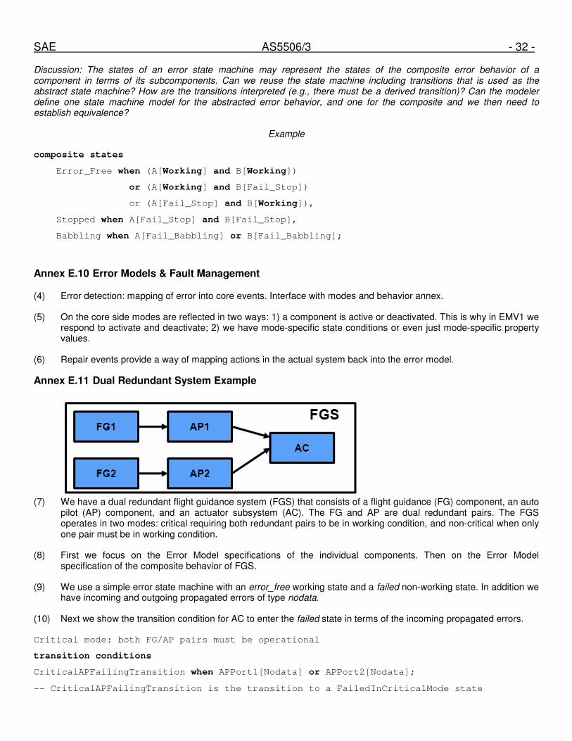
SAE AS5506/3 - 32 -
Discussion: The states of an error state machine may represent the states of the composite error behavior of a component in terms of its subcomponents. Can we reuse the state machine including transitions that is used as the abstract state machine? How are the transitions interpreted (e.g., there must be a derived transition)? Can the modeler define one state machine model for the abstracted error behavior, and one for the composite and we then need to establish equivalence?
Example
composite states
Error_Free when (A[Working] and B[Working])
or (A[Working] and B[Fail_Stop])
or (A[Fail_Stop] and B[Working]),
Stopped when A[Fail_Stop] and B[Fail_Stop],
Babbling when A[Fail_Babbling] or B[Fail_Babbling];
Annex E.10 Error Models & Fault Management
(4) Error detection: mapping of error into core events. Interface with modes and behavior annex.
(5) On the core side modes are reflected in two ways: 1) a component is active or deactivated. This is why in EMV1 we respond to activate and deactivate; 2) we have mode-specific state conditions or even just mode-specific property values.
(6) Repair events provide a way of mapping actions in the actual system back into the error model.
Annex E.11 Dual Redundant System Example
(7) We have a dual redundant flight guidance system (FGS) that consists of a flight guidance (FG) component, an auto
pilot (AP) component, and an actuator subsystem (AC). The FG and AP are dual redundant pairs. The FGS operates in two modes: critical requiring both redundant pairs to be in working condition, and non-critical when only one pair must be in working condition.
(8) First we focus on the Error Model specifications of the individual components. Then on the Error Model specification of the composite behavior of FGS.
(9) We use a simple error state machine with an error_free working state and a failed non-working state. In addition we have incoming and outgoing propagated errors of type nodata.
(10) Next we show the transition condition for AC to enter the failed state in terms of the incoming propagated errors.
Critical mode: both FG/AP pairs must be operational
transition conditions
CriticalAPFailingTransition when APPort1[Nodata] or APPort2[Nodata];
-- CriticalAPFailingTransition is the transition to a FailedInCriticalMode state

SAE AS5506/3 - 33 -
-- Non-critical mode: one operational FG/AP pair is sufficient
NoncriticalAPFailingTransition when APPort1[nodata] and APPort2[nodata];
-- NoncriticalAPFailingTransition is the transition to a FailedInNoncriticalMode state
-- APFailed is used as triggered condition for error state transition
(11) Now the composite error behavior for FGS. First we reflect the fact that the FGS operates in critical mode or non-critical mode by two different non-working error behavior states.
-- Define composite error behavior states of FGS
Annex Error_Model {**
Composite error behavior
Use myEM::ModalEM
Composite states
Noncriticalfailure when (AP1[failed] and AP2[failed]) or (FG1[failed] and AP2[failed]) …
-- failed is an non-working error behavior state in the subcomponent
Criticalfailure when 1 ormore (AP1[failed], AP2[failed], FG1[failed], FG2[failed],
AC[failed])
(12) We can also consider a single non-working error behavior state failure. We then use mode specific declarations to indicate the condition in which FGS is considered to have failed.
-- Define composite error behavior states of FGS in mode noncritical
Annex Error_Model {**
Composite error behavior
Use myEM::SimpleEM
Composite states
Failed when (AP1[failed] and AP2[failed]) or (FG1[failed] and AP2[failed]) …
Error_Free when others;
**} in modes (NonCritical);
-- Define composite error behavior states of FGS in mode critical
Failed when 1 ormore (AP1[failed], AP2[failed], FG1[failed], FG2[failed], AC[failed])
Error_Free when others;
**} in modes (Critical);
(13)
Annex E.12 A Triple Redundant Network Example
(14) This example models a triple redundant network with a voter/guard element that delivers a single result at the destination. This allows us to illustrate the composite error behavior model for the triple redundant network in terms of its individual AADL bus instances and the voter, as well as the component error behavior model of the abstracted triple redundant network as AADL bus. It allows us to illustrate the difference between a working and nonworking voter. It also allows us to explore how the working and non-working state of a bus component affects the error propagation along a connection.
(15)

SAE AS5506/3 - 34 -
Annex E.13 A Large Example (Example from Error Model Annex V1)
(1) This section presents an example high-level specification of a reconfigurable system having redundant subsystems. This system begins operation with three redundant copies of a subsystem operating, and a fourth spare subsystem that is initially powered down. The operating subsystems cross-vote to detect and isolate failures. When a failure of a subsystem is detected, the fourth subsystem can be powered-up and used to replace it. The overall system is considered operational as long as at least two of the powered-up subsystems are error-free, and no more than one subsystem has failed unsafely (is active and produces errors that must be masked).
package packageET
public
annex Error_Model {**
error type set InputOutputDataError
error type DataError;
error type No_Data extends DataError;
error type Bad_Data extends DataError;
end InputOutputDataError;
**};
end packageET;
package packageEM
public
annex Error_Model {**
error model Example
events
-- both events will have mode-specific occurrence values for powered,unpowered
Self_Checked_Fault: error event;
Unpowered_Uncovered_Fault: error event;
states
Error_Free: initial state {stateKind => working;};
Fail_Stopped: state {stateKind => nonworking;};
Fail_Unknown: state {stateKind => nonworking;};
transitions
SelfFail: Error_Free -[Self_Checked_Fault]-> Fail_Stopped;
UncoveredFail: Error_Free -[Uncovered_Fault]-> Fail_Unknown;
end Example;
**};
end packageEM;
(2) A subsystem is assumed to include self-checking algorithms, so that a subsystem is able to detect and fail-stop many but not all of its own failures. The error model declares two types of faults, one that can be successfully detected and still permit a subsystem to fail-stop, the other that produces a subsystem failure that either cannot be self-checked or that prohibits a subsystem from fail-stopping.

SAE AS5506/3 - 35 -
(3) It is also assumed that a subsystem can be dynamically powered up or powered down as a result of a mode switch during operation. Fault rates (e.g. as determined by MIL-HDBK-217F) are significantly different for powered versus unpowered equipment. Mode-specific property values permit different Occurrence rates to be specified
depending on whether a subsystem is powered or unpowered.
(4) A subsystem is initially in the Error_Free error state. A failed system can exist in one of two error states,
Fail_Stopped if self-checking has worked or Fail_Unknown if it has not. A system in the Fail_Unknown state
is assumed to exhibit arbitrarily bad behavior, e.g. it remains active sending misleading data, it cannot be powered-down at a mode switch.
(5) The propagations No_Data and Bad_Data represent different classes of errors propagated from a failed
subsystem. No_Data means it is visible to the receiver that the failed subsystem has fail-stopped. Bad_Data
means the receiver gets erroneous and misleading data from the failed subsystem, and the receiver must vote using other redundant sources of data to detect the failure.
(6) The error model declares transitions between error states depending on the kind of error event (internal fault).
system Subsystem
features
A: in data port;
B: in data port;
O: out data port;
A_Failed: out event port;
B_Failed: out event port;
Modes
Powered: initial mode;
Unpowered: mode;
annex Error_Model {**
error propagations
use packageET::InputOutputDataError;
Bad_Data : in propagation applies to A, B;
No_Data : in propagation applies to A, B;
Bad_Data : out propagation applies to O;
No_Data : out propagation applies to O;
flows
error source O[DataError];
error path A[DataError] -> O[DataError];
error path B[DataError] -> O[DataError];
error sink A[DataError];
error sink B[DataError];
end ;
**};
end Subsystem;
(7) We define component-specific conditions of incoming error propagation via component features and specify the transition they affect.

SAE AS5506/3 - 36 -
(8) The out propagated errors are declared to propagate being in a specific non-working error behavior state. While a subsystem is in the Fail_Unknown state, it sporadically propagates Bad_Data errors according to the
Occurrence model specified for Bad_Data while remaining in the Fail_Unknown state.
(9) The error behavior declaration also specifies a default set of Poisson occurrence rates for each kind of error event. Uncovered faults are 20 times less likely than covered ones (self-testing coverage approximately 95%). Faults in unpowered subsystems occur at 1/10 the rate of faults in powered ones.
(10) An active subsystem produces one output stream (declared as an out port O) and receives the outputs of the two other active subsystems (declared as in ports A and B). Each subsystem votes its own result with that of its sibling subsystems to detect and isolate failures. When a failure in a sibling subsystem is detected and isolated, an event will be raised.
system implementation Subsystem.Notional
annex Error_Model {**
component error behavior
use packageEM::Example;
transition conditions
-- these conditions represent the Guard_In declarations in the EM V1 Example
mask when (A[NoError] and B[No_Data, Bad_Data])
or (A[No_Data, Bad_Data] and B[NoError]),
uncoveredfail when (A[Bad_Data] and B[Bad_Data]);;
selffail when A[No_Data] and B[No_Data];
detection events
A_Failed when (A[No_Data] or A[Bad_Data]) and B[Error_Free];
B_Failed when A[Error_Free] and (B[No_Data] or B[Bad_Data]);
end ;
Properties
Occurrence => (1E-4 poisson in modes (powered),
1E-5 poisson in modes (unpowered))
applies to Self_Checked_Fault;
Occurrence => 0.05E-4 poisson in modes (powered),
0.05E-5 poisson in modes (unpowered))
applies to Uncovered_Fault;
**} ;
end Subsystem.Notional;
(11) The Subsystem implementation declaration models the voting protocols that are to be realized in the final physical system. The behavior of the actual physical subsystem must be verified against this specification. These are specifications of nominal behavior. They are written assuming this subsystem is error-free and typically only name error states of other components. An erroneous subcomponent by definition no longer obeys its nominal specification, and in particular an erroneous subsystem may not exhibit the specified voting behaviors. The voting behaviors of other error-free subsystems will determine how the overall system responds to errors in a given individual subsystem.
(12) A subsystem votes by comparing three values, its two inputs and its own internal result. Among the three values being voted, if two agree and one persistently disagrees, then the one that persistently disagrees is assumed to have failed. If a subsystem believes it has failed then it does not raise an event, it simply attempts to fail-stop and

SAE AS5506/3 - 37 -
relies on the other two subsystems to detect this. Thus, each subsystem only has two outgoing events, one for the other subsystems that it monitors, and does not have a third outgoing event to signal a self-check failure.
(13) In this model, any other pattern of error propagations is conservatively assumed to place a subcomponent in an unknown error state. This is declared by the “Bad_Data when others” term in the transition condition
declarations. For example, if a sibling subsystem has visibly fail-stopped, and the internal result disagrees with the value received from the only other operating subsystem, then the model assumes worst-case behavior. An actual subsystem might attempt to continue operating, or might attempt to fail-stop, but these are both modeled in this specification as unsafe failures of that subsystem.
(14) An actual physical subsystem would likely make a decision only after seeing persistent disagreement, for example n miscompares out of m consecutive values, in order to be robust to transient faults and errors. Transient fault events and transient error states could be included in an error model, but this example only models permanent faults and failures.
(15) The difficulty in modeling this protocol lies in deciding what assumptions to make about its behavior when one of the subsystems is in a Failed_Unknown error state and propagating Bad_Data errors. This specification
assumes that Bad_Data will be detected by an error-free subsystem providing at least one of the other subsystems
is error-free. In an actual system a Byzantine error may occur, which is to say a subsystem in a Failed_Unknown
state may send error-free data to one sibling subsystem (which detects no errors) and erroneous data to the second sibling subsystem (which detects an error). The two error-free subsystems do not have a consensus on whether a failure has occurred. We will return to this issue in a few paragraphs.
system Dependable_System
end Dependable_System;
system implementation Dependable_System.Notional
subcomponents
S1: system Subsystem.Notional in modes (S123, S124, S134);
S2: system Subsystem.Notional in modes (S123, S234, S124);
S3: system Subsystem.Notional in modes (S123, S134, S234);
S4: system Subsystem.Notional in modes (S124, S134, S234);
connections
data port S2.O ->> S1.A in modes (S123);
data port S3.O ->> S1.B in modes (S123);
data port S1.O ->> S2.A in modes (S123);
data port S3.O ->> S2.B in modes (S123);
data port S1.O ->> S3.A in modes (S123);
data port S2.O ->> S3.B in modes (S123);
data port S2.O ->> S4.A in modes (S234);
data port S3.O ->> S4.B in modes (S234);
data port S4.O ->> S2.A in modes (S234);
data port S3.O ->> S2.B in modes (S234);
data port S4.O ->> S3.A in modes (S234);
data port S2.O ->> S3.B in modes (S234);

SAE AS5506/3 - 38 -
data port S4.O ->> S1.A in modes (S134);
data port S3.O ->> S1.B in modes (S134);
data port S1.O ->> S4.A in modes (S134);
data port S3.O ->> S4.B in modes (S134);
data port S1.O ->> S3.A in modes (S134);
data port S4.O ->> S3.B in modes (S134);
data port S2.O ->> S1.A in modes (S124);
data port S4.O ->> S1.B in modes (S124);
data port S1.O ->> S2.A in modes (S124);
data port S4.O ->> S2.B in modes (S124);
data port S1.O ->> S4.A in modes (S124);
data port S2.O ->> S4.B in modes (S124);
modes
S123: initial mode;
S234, S134, S124: mode;
T1_4: S123 -[ S2.A_Failed, S3.A_Failed ]-> S234;
T2_4: S123 -[ S1.A_Failed, S3.B_Failed ]-> S134;
T3_4: S123 -[ S1.B_Failed, S2.B_Failed ]-> S124;
annex Error_Model {**
composite error behavior use model packageEM::Example;
Error_Free when 2 ormore
(S1[Error_Free],
S2[Error_Free],
S3[Error_Free],
S4[Error_Free])
and 1 orless
(S1[Fail_Unknown],
S2[Fail_Unknown],
S3[Fail_Unknown],
S4[Fail_Unknown]),
-- original model did not have a specification for Fail_Stopped state
Fail_Unknown when others;
-- Guard transition => now specified in Behavior Annex
-- T1_4 when
-- (S2.A_Failed[Error_Free] and S3.A_Failed[Error_Free])
-- or (S2.A_Failed[Bad_Data] and S3.A_Failed[Bad_Data]);
-- Guard transition =>
-- T2_4 when

SAE AS5506/3 - 39 -
-- (S1.A_Failed[Error_Free] and S3.A_Failed[Error_Free])
-- or (S1.A_Failed[Bad_Data] and S3.A_Failed[Bad_Data]);
-- Guard transition => now specified in Behavior Annex
-- T3_4 when
-- (S2.A_Failed[Error_Free] and S2.A_Failed[Error_Free])
-- or (S2.A_Failed[Bad_Data] and S2.A_Failed[Bad_Data]);
**} ;
end Dependable_System.Notional;
(16) A dependable system consists of four subsystems and four modes of operation. In each mode of operation, three of the four subsystems are active. The mode names in this example have the form Sxyz, where x, y and z denote the subsystems that are active in that mode.
(17) In each mode of operation, the three subsystems that are supposed to be powered-up and active are cross-connected. Each subsystem listens to both of the other active subsystems on different input ports, and its output is connected to both of the other active subsystems.
(18) Subsystems that detect failures raise events that are ultimately connected to mode transitions. The labeling events of each transition have an associated Guard_Transition property expression that defines the conditions under
which a transition will be taken. This model specifies that a system will only switch modes when two subsystems raise an event requesting the same mode transition. An actual physical system might implement this, for example, by having each processor vote on the incoming error connections, and enter a mode switch consensus protocol only when the two events specified for the current mode of operation occur within a maximum time separation.
(19) The Guard_Transition property expression shows that a false transition might occur if one of the two
subsystems has failed in an unknown state and falsely raises an event. This can take an error-free subsystem off-line and leave a failed subsystem on-line. This does not necessarily lead to immediate failure in the initial mode of operation, since the newly powered-up subsystem together with the remaining error-free subsystem can mask errors from the failed subsystem. However, it makes suboptimal use of redundant resources by wasting an error-free subsystem. The system is now only one fault away from unsafe system failure.
(20) To give an example illustrating the above two paragraphs, if both S1 and S3 are Error_Free and request a mode transition, then that transition will occur. If both S1 and S3 have failed babbling (are in a Bad_Data error state) and request a mode transition, then that transition will occur. The former case is a correct and desired behavior, the latter case is an incorrect and undesired behavior that nevertheless occurs because both S1 and S3 have simultaneously failed babbling and simultaneously erroneously requested a mode change.
(21) As noted earlier, it is also possible that a mode transition would be lost if a Byzantine error occurs and only one of the error-free subsystems detects that subsystem failure. This would be taken into consideration if the modeling and analysis tool considered all possible subsets of consequent in error propagation transitions, in particular
considered the case where a Bad_Data error propagated to one Error_Free subsystem but not the other.
Again, this does not necessarily lead to immediate failure because the two error-free subsystems can mask the errors of the failed one, but it makes suboptimal use of the available resources by failing to bring the available spare on-line. The system is now only one fault away from unsafe system failure.
(22) The error state of the system as a whole is defined as a function of the error states of the subsystems. The system is considered to be operating acceptably when at least two subsystems are active and error-free, and no more than one subsystem has failed unsafe.
Annex E.14 Misc Material
Annex Document E For individual software components we may have a rich set of faults as illustrated in Figure 3 (from Vangelis presentation). Some of the illustrated faults are not intrinsic to the software, but are propagations from interacting components or execution platform resources being used. These faults can get mapped into propagation error types for propagation outside a fault containment unit (process/partition). Within a fault containment unit the effect may be more extensive.

SAE AS5506/3 - 40 -
Figure 3 Software-related Fault Types
(23)

SAE AS5506/3 - 41 -
(24) from Vangelis

SAE AS5506/3 - 42 -
(25)
(26) from Vangelis: need for hierarchy in reusable error models. Possibly with “multiple” inheritance.
(27)