Embed Size (px)
Citation preview

N hi) 2C
c'. p
ocr) 2ä ü£
AERODYNAMIC DESIGN OF A OO.VTIW'O'JS HYPERVELOCITY Y7I,\D Tüi\\\IL
PlVjrtn;/
A
A \ i ,x
~^ f~
22 MARCH 1962
— 2
> SHm
S i ru DO * =
_j %. . ~U|
^ ^^s g^=g O
l^a C\l I
OH«
031
0
C\J
HJ^^a • Ci
~ '——ZtUl —J =i — 'S /—s
U1 'M I L J Oh'ill.0 i * • \ •• 111. U . I U « • i H 11".. Li".:) -J ( u t I U i;. 1 , i i i 11 1 i. Ur.ii, 1 fl rM / 1
1 . i ; '. I 1 !
„OCRTY OF U. S. AIR FQRQI PROPERTY OF ^
AF 40(600)1000
e ,7 T

NOLTR 62-20
Aeroballistics Research Report No, 172
AERODYNAMIC DESIGN OF A CONTINUOUS HYPERVELOCITY WIND TUNNEL
by
K, R„ Enkenhus, E„ L. Harris, W. J. Glowacki, E, F. Maher, and P. A, Cerreta
ABSTRACT: An aerodynamic design study was made of a continuous, hypervelocity wind tunnel for simulating the flight environment of long-range ballistic missiles and glide vehicles at Mach numbers up to 20. Nozzles were designed by the method of characteristics for high-temperature air in dissociative and vibrational equilibrium. Since non-equilibrium flow is expected to occur under many conditions, the effect of a finite oxygen recombination rate on the flow in hypersonic nozzles was determined for a wide range of supply conditions. The nozzle turbulent boundary-layer growth and heat transfer were calcu- lated by a momentum-integral method employing thermodynamic and transport properties appropriate to high-temperature air. The extremely high heat-transfer rates near the nozzle throat create a severe cooling problem. Both convective cooling, using water or liquid metals, and film cooling, with air or water injection, were studied. The application of the electric arc as an air heating device, and the oerformance of a hyper- sonic diffuser were also examined. Conclusions are drawn from the results of this study regarding the range of free-flight conditions which can be simulated in the wind tunnel.
PUBLISHED APRIL 1962
U. S. NAVAL ORDNANCE LABORATORY WHITE OAK. MARYLAND

NOLTR 62-20 22 March 1362
Aerodynamic Design of a Continuous Hypervelocity Wind Tunnel
This report contains the results of a preliminary aerodynamic design study which was carried out at the U. S. Naval Ordnance Laboratory to determine the feasibility of simulating re-entry flight conditions in a continuously operating wind tunnel.
This work was jointly sponsored by the Bureau of Naval Weapons under Task No. PR-10 and by the U. S. Naval Ordnance Laboratory under Task No. FR-61.
W. D. COLEMAN Captain, USN Commander
FLORIAN GEINEDER By direction
ii

NOLTR 62-20
CONTENTS
Page Introduction 1 Nozzle Supply Conditions, Mass Flow, and Power Requirements 2 True-Temperature Operation 2 Condensation-Threshold Operation 3
Air Heaters 4 The Status of Air Heaters ..... 4 Electric Arc Operation at Elevated Supply Conditions 6
Hypervelocity Nozzles 8 Nozzle Design 8 Nozzle Performance 9
Non-Equilibrium Flow in Nozzles . . ... . * . . . .10 Theoretical Procedure .10 Results 11
Nozzle Throat Cooling .... 12 Convective Water Cooling ...... ...12 Film Cooling 12
The Hypervelocity Diffuser and Pusping System .... 13 The Diffuser 13 Pumping Requirements ...... 14
Conclusions 14 References ......... 17
iii
NOLTR 62-20
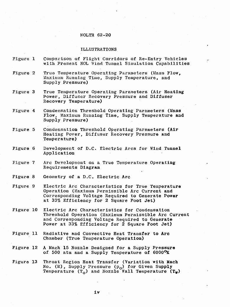
ILLUSTRATIONS
Figure 1 Comparison of Flight Corridors of Re-Entry Vehicles with Present NOL Wind Tunnel Simulation Capabilities
Figure 2 True Temperature Operating Parameters (Mass Flow, Maximum Running Time, Supply Temperature, and Supply Pressure)
Figure 3 True Temperature Operating Parameters (Air Heating Power, Diffuser Recovery Pressure and Diffuser Recovery Temperature)
Figure 4 Condensation Threshold Operating Parameters (Mass Flow, Maximum Running Time, Supply Temperature and Supply Pressure)
Figure 5 Condensation Threshold Operating Parameters (Air Heating Power, Diffuser Recovery Pressure and Temperature)
Figure 6 Development of D.C. Electric Arcs for Wind Tunnel Application
Figure 7 Arc Development on a True Temperature Operating Requirements Diagram
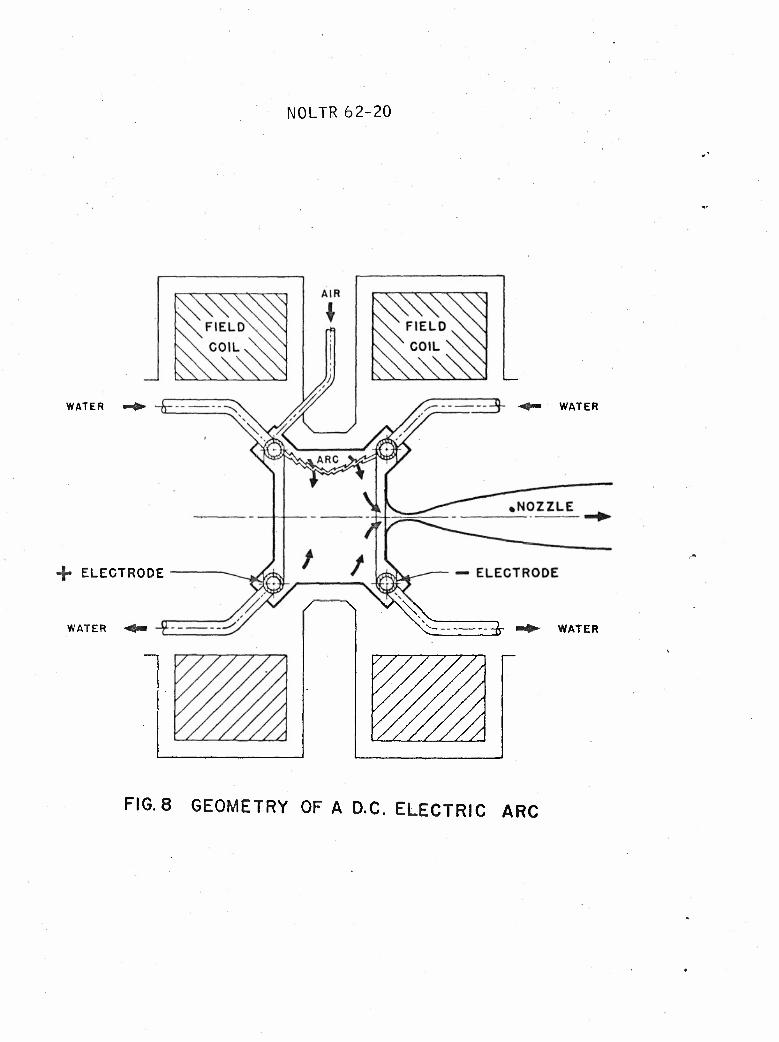
Figure 8 Geometry of a D.C. Electric Arc
Figure 9 Electric Arc Characteristics for True Temperature Operation (Maximum Permissible Arc Current and Corresponding Voltage Required to Generate Power at 33% Efficiency for 2 Square Foot Jet)
Figure 10 Electric Arc Characteristics for Condensation Threshold Operation (Maximum Permissible Arc Current and Corresponding Voltage Required to Generate Power at 33% Efficiency for 2 Square Foot Jet)
Figure 11 Radiative and Convective Heat Transfer to Arc Chamber (True Temperature Operation)
Figure 12 A Mach 15 Nozzle Designed for a Supply Pressure of 500 atm and a Supply Temperature of 6000°K
Figure 13 Throat Region Heat Transfer (Variation with Mach No. (M), Supply Pressure (p0) for Given Supply Temperature (TQ) and Nozzle Wall Temperature (Tw)
iv

NOLTR 62-20
Figure 14 True Temperature Operating Parameters (Peak Nozzle Throat Convective and Radiative Heat Transfer Rates, Pumping Speed and Boundary Layer Displacement Thickness at Nozzle Exit)
Figur© 15 Condensation Threshold Operating Parameters (Paak Nozzle Throat Connective Heat Transfer Rate (Radiation Negligible), Pumping Speed and Boundary Layer Dis- placement Thickness at Nozzle Exit)
Figure 16 Oxygen Recombination in a Conical Mach 15 Nozzle (Parabolic Throat, 6 ft Length)
Figure 17 Fraction of Oxygen by Weight Which Freezes in a Mach 15 Conical Nozzle (Parabolic Throat, 6 ft Length)
Figure 18 Effect of Finite Oxygen Recombination Rate on Mach Number Obtained in a Mach 15 Conical Nozzle (Parabolic Throat, 6 ft Length)
Figure 19 Calculations of Convective Water Cooling of Mach 12 Copper Nozzle Throat
Figure 20 True Temperature Operating Boundaries (2 Square Foot Jet at Nozzle Exit with 400°R Static Tempera- ture)
Figure 21 Condensation Threshold Operating Boundaries (2 Squre Foot Jet at Nozzle Exit)

NOLTR 62-20
SYMBOLS
Ä nozzle cross-sectional area
B magnetic field strength
1 arc current
Kg atom recombination rate constant
M Mach number
p pressure
q connective heat-transfer rate per unit area
Q power supplied to arc electrodes
r nozzle radius
T temperatures
Ü linear speed of arc filament
¥ voltage between arc electrodes
x distance along nozzle axis, measured from throat
ö boundary-layer thickness
6* boundary-layer displacement thickness
r\ arc efficiency
y ratio of specific heats
Subscripts
o supply condition
* throat value
p test-section value
2 diffuser exit value
Vi

NOLTR 62-20
INTRODUCTION
The use of wind tunnels for aerodynamic research and development has so many advantages that the technique has been of basic importance from the time of the Wright brothers to the present day. In recent years, however, performance characteristics have advanced so rapidly that the speed, altitude, and temperature environment of some missiles currently in operation far exceed the simulation capabilities of existing continuously operating hypersonic wind tunnels. Missile and glide vehicle re-entry corridors, as determined in reference (1), are compared with the altitude and Mach number simulation capabilities of continuous wind tunnels at the Naval Ordnance Laboratory in figure 1. It is seen that, in order to cover the complete range of re-entry conditions, a facility is required which will extend operation from Mach 10 to Mach 25 for a wide range of altitudes.
At low Mach numbers, satisfactory results can generally be obtained by reproducing the free-flight Mach and Reynolds numbers without duplicating the thermal environment. Thus, in existing wind tunnels, it is usual to heat the air only sufficiently to avoid liquefaction in the test section. At high Mach numbers, however, the elevated flow temperatures encountered produce significant chemical Changes in the air. These changes include the dissociation" of oxygen and nitrogen and the formation of nitric oxide. Because it is chemical effects which invalidate the extrapolation of low-temperature aerodynamic theories, it is of the greatest interest to duplicate them by operating a hypervelocity facility at the free-flight values of Mach number, temperature, and pressure. Since it is usually necessary to employ a scale model, the Reynolds number will be less than in free flight. Furthermore, if relaxation phenomena are important, the inviscid flow over the model will no longer be completely similar to that in free flight. In the final analysis, the objectives of any investigation must dictate the choice of similarity parameters.
The purpose of this report is to investigate the design and performance of a continuous, hypervelocity wind tunnel duplicating free-flight Mach number, temperature, and pressure, which will hereafter be referred to as "true-temperature opera- tion." Since the running, time required for most investigations is rather indefinite (a period of several minutes, or perhaps only a few seconds being sufficient) the term "continuous" will be taken to mean merely that the facility is capable of opera- ting for an extended period.
There are a variety of facilities with very short operating times which are being used for re-entry testing, including the

NOLTR 62-20
shock tube, the shock tunnel, and the aeroballistics range. The short testing time simplifies the design of these facilities, but it also leads to difficulties in the measureateat and inter- pretation of data« It is therefore worthwhile to examine the capabilities of the conventional wind tunnel as a tool for advanced flight research.
Due to technical problems characteristic of continuously operating wind tunnels, true-temperature operation is only possible in a limited portion of the re-entry spectrum. However, much additional useful information can be obtained by either lowering the air temperature to extend operation to higher Mach numbers, or overheating the air to obtain con- siderably higher velocities but with low Mach numbers. The performance obtainable by what will be termed "condensation- threshold operation" (i.e., heating the air just sufficiently to avoid liquefaction in the test section) was analyzed in detail. The alternative of overheating the air yields very high velocities with modest supply pressures, but results in a partially dissociated gas in the test section which differs in properties from the ambient air encountered in free flight. This mode of operation is, therefore, of little interest to the aerodynamicist.
NOZZLE SUPPLY CONDITIONS, MASS FLOW, AND POWER REQUIREMENTS
True-Temperature Operation
The first consideration in the design of a wind tunnel is the determination of the nozzle air supply temperature and pressure necessary to achieve the desired test section condi- tions. An investigation described in a subsequent section indicated that for the range of conditions for which true- temperature operation would be possible for a representative hyperveloclty facility the departure from equilibrium flow conditions in nozzles is small. It was therefore assumed that the air undergoes an isentropic expansion in the nozzle while remaining in thermodynamic equilibrium. The values of supply temperature and pressure required could then be found from a plot of the properties of high-temperature air on an enthalpy- entropy diagram (Mollier chart) (ref. (2)).
The supply temperature and pressure, mass flow, and running time for true-temperature Operation are shown in figure 2. The test section isentropic core area of the facility was chosen as 2 ft2. The test section static tempera- ture was selected as 222°K (400°R), an average value for the upper atmosphere. The abscissa of figure 2 is the test section Mach number, and the Ordinate is the static pressure with an

NOLTR 62-20
inverted logarithmic scale«, The altitude corresponding to the static pressure, based on the 1956 ARDC model atmosphere, is shown on the right-hand side, of the figure. The supply enthalpy required is indicated along the top of the graph. The running times are based on the choice of 3000 lbs of air stored in the high pressure bottle field supplying the tunnel. The operating boundaries of a particular, representative hypervelocity wind tunnel are also indicated« The right-hand boundary of 500 atmospheres supply pressure, represents, as will be shown later, about.the maximum value feasible in any true-temperature wind tunnel. The upper boundary is fixed at a diffuser recovery pressure of 5 mm Hg, which is about the lower limit for satisfactory operation with a mechanical pumping system. Operation can, of course, be extended to considerably lower pressures by employing a high vacuum pumping system, A limit then results when the boundary layer completely fills the nozzle at very low pressures. The lower boundary corresponds to 5 megawatts of power input to the air. This is approximately the maximum power which can be generated in a single D.C, electric arc»
The air heating power (i,e„, the power required to heat the air to the supply enthalpy at the mass flow rates shown in figure 2) is given in figure 3. The diffuser recovery pressure and temperature, which are also shown, will be dis- cussed later. It can be seen from the figure that the simu- lation of low altitudes leads to large power requirements,
Condensation-Threshold Operation
Condensation-threshold operation is possible at much higher Mach numbers than true-temperature operation, not only because a minimum supply temperature is required, but also because the supply pressures are much lower for a given Mach number. The analysis for condensation-threshold operation is identical to that for true-temperature operation, except that the test section static temperature, instead of being 222°K, is now the temperature at which condensation occurs, as found from reference (3) «,
The supply temperature and pressure, mass flow, and running time for condensation-threshold operation are shown in figure 4» It is seen that a supply temperature of 2800°K and a supply pressure of 700 atmospheres are sufficient to achieve Mach 20, The wind tunnel operating boundaries cor- respond to the same limits discussed above, except that a limit of 10 lb/sec was placed on the mass flow^ and the maximum supply pressure was increased to 1000 atmospheres«. An electric resistance heater should provide the necessary supply temperatures at this pressure. The mass flow rate limit is rather arbitrary; it was selected to provide a

Q , %
NOLTR 62-20
minimum running time of about 4 minutes with a 2500 lb air supply. (500 lbs of the total of 3000 lbs stored is used to fill the heater volume*)
The air heating power for condensation-threshold operation is shown in figure 5„ The diffuser recovery pressure and temperature are also given, but will be discussed later» It will be seen that the power required is less than half that needed for true-temperature operation at the same static pres- sure and Mach number.
AIR HEATERS
The Status of Air Heaters
In recent years, the thermal storage heater has been used with hypersonic wind tunnels. Such a heater consists of a cylindrical container, filled with ceramic pebbles which are preheated before the run. The air is brought to the pebble temperature while passing through the bed. A nearly constant air temperature can be maintained until the pebbles at the downstream end of the bed first begin to cool. An investi- gation of this type of heater employing alumina pebbles reveals that it is satisfactory for providing temperatures of only a little over 0t6ÖQ3K> The use of zirconia pebbles theoreticallyL would allow operation) at temperatures approaching (2500°^ but in practice a great/deal of difficulty has been encountered with the fusing of the bed at the higher temperatures«
Condensation-free operation at Mach 20 could not be achieved with a pebble bed heater, but a graphite resistance heater is an interesting alternative. Such a heater would have to employ nitrogen instead of air to avoid oxidation of the graphite» Since the degree of dissociation of the air is negligible for condensation-threshold operation, it may be expected that an adequate simulation will be obtained using nitrogen» Helium is even easier to use than nitrogen since its condensation temperature is much lower. However, because it is a monatomic gas, the ratio of specific heats equals 5/3 instead of 7/5 characteristic of a diatomic gas, and the flow over the body is not similar to that of air.
The only device currently available which is capable of continuously generating very high temperatures in air at high pressures is the A.C. or D„C. electric arc (refs. (4) and (5)). The electric arc was first used as a wind-tunnel air heater around 1957, when water stabilized arcs were developed for materials testing. These arcs operated near atmospheric pressure and generated very high enthalpies» Another type of arc actually used was the air stabilized arc

NOLTR 62-20
with carbon electrodes, but severe contamination was pro- duced which rendered the device unsatisfactory for aerody- namic tests.
The basic principle which has allowed the development of air arcs with low contamination has been the use of water- cooled copper electrodes with the arc filament rotated by the force exerted by an externally applied magnetic field. The field spins the filament around the periphery of the electrodes at a high enough speed to avoid local melting where the arc "spot" touches the metal« The electrodes are thus able to operate indefinitely without overheating. In the interest pf economy, in most of the arc development work to date, the surrounding arc chamber has been merely a heat sink, without water cooling passages which would have allowed continuous operation» The short running tiroes of a minute or less usually reported are due to the absence of chamber cooling, and do not indicate an actual limitation on operating times« For example, the magnetically dxij?Jfi„.Berkeland_-Eyde..XA«C^^ arc was run continüousiy for periods of weeks without mainte- nanceat a power level of 4 megawatt's "and" a pressure of a few atmospheres fifty years ago in a plant producing commerical nitrogen compounds (rex.(6)).
The increase in the operating pressure and power level of arcs for wind-tunnel applications over the past few years is shown in figure 6. The time scale indicates the date at which the deyices were first tested« The points were plotted from representative information available in references (6) to (9)« While figure 6 indicates a rapid rise in operating pressure over the past few years, the present state of the art is represented by a pressure of 150 atmospheres. Further increases in the operating pressure and power level of electric arcs are severely limited by the associated rise in conduction and radiation losses to the arc chamber and the heating of the electrodes«,
The arc data of figure 6 are plotted on a true-temperature operating diagram in figure 7, The point representing the performance of each arc is plotted on the basis of its operating pressure and temperature. The figure shows that even though the application of the electric arc is still in its infancy, the performance necessary to cover a wide range of re-entry conditions has been achieved.
In designing an electric arc, the first decision must be the selection of either direct or alternating current. The latter may include operation with 3 or more A.C. phases. The cost of the power supply for an A.C. arc is much lower than for the D.C. arc, but the question of introducing enthalpy fluctuations in the flow requires careful consideration. It may be anticipated that if an A.C. arc is used, the enthalpy

NOLTR 62-20
of the air will follow the instantaneous power fluctuations unless the air is stored in a plenum chamber for a period of many A.C. cycles before being fed to the nozzle. The use of such a plenum chamber appears to be rather unsatisfactory in practice due to the large enthalpy losses the gas will experi- ence while in the plenum chamber (ref. (7)). In order to minimize heat losses while avoiding fluctuations in enthalpy, it is therefore desirable to employ a D.C. arc of the most compact configuration possible, with the electrodes placed close to the nozzle throat.
Fluctuations in the instantaneous power can also occur in a D.C. arc due to the fact that the arc filament follows a sinuous path between the electrodes so that arc length may vary in a random manner. The resulting fluctuations in enthalpy, as manifested by velocity variations at the nozzle exit, have been experimentally observed by Jedlicka (ref, (6)). The fluctuations may be made small, however, by using a power supply with a series ballast resistor equal in value to the arc resistance.
Electric Arc Operation at Elevated Supply Conditions
Some theoretical estimates of the degree to which arc performance may be extended have been made based on experi- mental results obtained at the Ames Research Center (ref. (6)) for a D.C. arc having an electrode configuration similar to that shown in figure 8. It was found that in order to avoid electrode melting, an are filament carrying a current I must be spun at a linear speed Ü which is proportional to 1^.
The magnetic field strength B required to spin the arc at this speed is determined from the fact that the driving force, which is proportional to BI, must overcome the aerodynamic drag of the arc filament, which is proportional to p0u*2 at a given operation temperature, where p0 is the supply pressure. From the above considerations, it can be deduced that the maximum permissible arc current will be proportional to
. The constant of proportionality can be estimated (S3 from the experimental data of references (6) and (7).
Once the maximum permissible current is established, the corresponding minimum voltage required to generate a power of Q megawatts in the air with an efficiency n is
Q x 106 ,,v Vmin - * . (1)
*!• imax

NOLTR 62-20
Efficiencies from 50 to 75 percent have been measured in various laboratories, based on the assumption that the enthalpy increase of the air stream may be determined by subtracting the heat passing into the cooling water and arc chamber walls from the total energy supplied. Experiments conducted at Ames indi- cate, however, that a part ojj^jbhe...v.energx,,ÄHPPlied,„to =the_ air goes into the formationi ...of chemical compounds in the very hot coreof the arc so that the energy available for producing E jet with a high velocity is less than normally supposed (ref. X&TT» This phenomenon not only increases power requirements but also introduces extraneous compounds into the air stre,ajn. This effect alters the flow and may possibly cause errors in heat-transfer measurements through catalytic reaction at the model surface. Insufficient experimental data are available to evaluate the seriousness of this problem.
The enthalpy of the gas at the nozzle throat can be cal- culated from measured values of supply pressure and mass flow, if it is assumed that the stagnation enthalpy in the supply chamber is uniform, and also that the flow to the throat remains in thermodynamic equilibrium. By this means, in refer- ence (6), an efficiency of 35 percent was found for a Plasmadyne arc, and only 20 percent for the Winovich arc. However, the efficiency of the latter remained constant up to 100 atmos- pheres«, Although the heat-transfer rate to the arc chamber walls may be expected to increase roughly in proportion to the pressure at a constant temperature, the energy content of the gas is larger in the same proportion. It is therefore reasonable to anticipate that to a first approximation, the efficiency will be independent of pressure at a fixed tempera- ture.
Curves of maximum permissible arc current and the cor- responding minimum voltage required are shown for true-tempera- ture operation in figure 9, based on an arc efficiency of 0.33 and a magnetic field strength of 10,000 gauss. A corresponding plot for condensation-threshold operation is given in figure 10. These figures indicate how the arc operating current and voltage are specified by the necessity of avoiding electrode burnout. At low supply pressures, very large currents are permissible and the voltage required to generate the desired power level is small. In this region, the arc current may be considerably reduced to provide a large safety factor against electrode failure without having to raise the voltage to excessive levels. Conditions are most severe in the lower right-hand corner of the operating regions shown in figures 9 and 10, since the voltage required to generate the desired power is already very high even at the maximum permissible value of current. The problem of insulating the electrodes from the chamber wall at high voltages may be expected to present difficulties. The voltage could be reduced by a factor of 2 by connecting 2 similar arc units to the same

NOLTR 62-20 «
nozzle, but additional enthalpy losses may be anticipated since the electrodes cannot be as close to the throat. The above analysis takes into account the principal factors involved in cooling the arc electrodes. It appears that operation of the electrodes is feasible at considerably higher pressures than those currently in use.
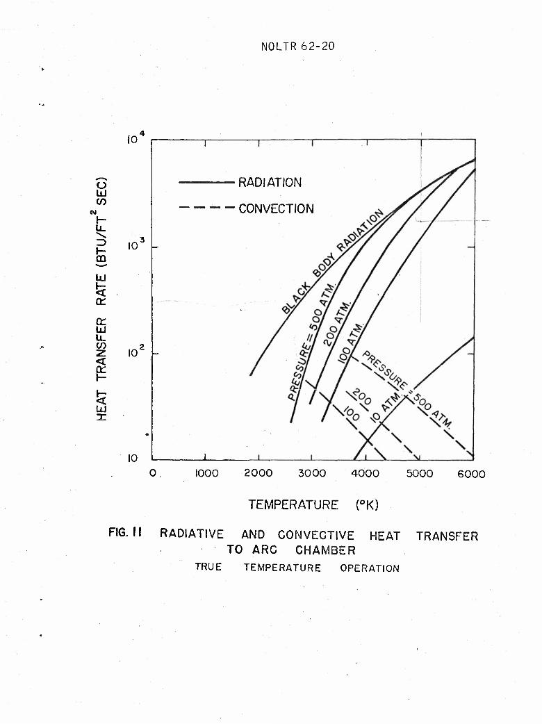
The calculation of the radiative and convective heat- transfer rates to the chamber walls is difficult because the geometry is complex, and because the enthalpy distribution is non-uniform and varying with time due to the spinning of the arc. In order to make some theoretical estimates it was therefore necessary to employ a simplified model. The radiative heat-transfer rate to the chamber wall was estimated assuming a uniform temperature in the arc chamber, and using the erais- sivity data for high-temperature air in reference (10). The direct radiation from the very hot core of the arc filament to the walls was not taken into account. At high operating pressures, however, this radiation will be absorbed by the air. The convective heat-transfer rate was estimated by assuming a fully-developed turbulent pipe flow in the arc chamber.
The radiative and convective heat-transfer rates for true- temperature operation are shown as a function of supply tempera- ture and pressure in figure 11. At high supply pressures and temperatures the radiative heat-transfer rate approaches the black body,limit. It may be seen that the convective heat- transfer rate is very small compared with the radiative heat= transfer rate in the arc chamber. As will be seen later, the opposite is true at the nozzle throat. The total heat-transfer rates shown in figure 11 are within the range for which con- vective water cooling of the wall is still theoretically possible. The power losses are, however, very large at high temperatures and pressure; for example, at p0 - 500 atmos- pheres and T0
m 6000°K the losses in a chamber of one-square- foot area would be about 7 megawatts. It may be concluded that there are no inherent barriers preventing the development of arcs operating at several hundred atmospheres, but the engineering problems become increasingly difficult as the supply conditions are raised.
HYPERVELOCITY NOZZLES
Nozzle Design
Computer programs have been developed at the U.S, Naval Ordnance Laboratory for the design of contoured axially symmetric nozzles for high-temperature air in thermodynamic equilibrium, A complete report on the method will soon fee
8

NOLTR 62-20
published. The supersonic isentropic core contour was first computed by the method of characteristics, using the thermo- dynamic properties of air from reference (11), A smooth sub- sonic contour was added, with the flow parameters along its boundary determined assuming a one-dimensional expansion. The Reynolds number based on the boundary-layer momentum thickness was sufficiently high to suggest that the boundary layer would be turbulent for most operating conditions. The turbulent boundary-layer growth was computed by a numerical integration of the boundary-layer momentum integral equation along the entire contour, starting in the subsonic entrance, employing the transport properties of air as given by Hansen (ref. (12)), The convective heat-transfer rate to the nozzle wall was also determined as part of the boundary-layer calculations. The nozzle wall co-ordinates were obtained by adding a boundary- layer correction, equal to the boundary-layer displacement thickness, to the co-ordinates of the isentropic contour.
Nozzle Performance
The contour of a Mach 15 nozzle designed for true-tempera- ture operation, with a supply pressure of 500 atmospheres and a supply temperature of 6000°K is shown in figure 12, The nozzle has an isentropic core exit area of 2 square feet, and a length of 16,7 feet. The maximum core expansion angle is 10 degrees. The boundary layer at the nozzle exit is about 1.5 feet thick, and only about 0,8 square feet of uniform flow remains after the boundary-layer correction is added.
The turbulent boundary-layer growth in hypervelocity nozzles may be described as follows: In the subsonic entrance section, the acceleration of the air thins the boundary layer so that at the throat the boundary-layer thickness ö is only of the order of a few thousandths of an inch, and the displacement thick- ness o* is about one tenth of this value. The boundary layer then grows almost linearly with distance to the exit, where the displacement thickness is about 80 percent of the total boundary-layer thickness.
The boundary-layer growth calculations in the supersonic part of the nozzle were carried out using the Van Driest turbu- lent skin-friction formula, which was modified for application to a partially dissociated boundary layer with pressure gradient. The heat transfer was found from the skin friction by using Reynolds analogy. To calculate the convective heat-transfer rate near the nozzle throat, the Blasius incompressible skin- friction law was used for the subsonic contour, since this formulation was found to yield the best agreement with the experimentally measured turbulent heat-transfer rates at low Mach numbers in a partially dissociated boundary layer with a highly cooled wall (ref. (13)).

NOLTR 62-20
Typical results for the convective heat-transfer distri- bution along the nozzle axis in the vicinity of the throat, showing the sharp peak, are given in figure 13 for a family of hypervelocity nozzles. The heat-transfer rate falls rapidly from thousands of BTU/ft^sec at the throat, to the order of one BTU/ft^sec at the nozzle exit. It^ was found that the nozzle throat radius of curvature had a^veryminor effect on the peak convective heat-transfer rate, although a larger radius of curvature tends to broaden the region of high heat- transfer rates.
The radiative heat-transfer rate in the vicinity of the nozzle throat was estimated by calculating the energy absorbed by the wall of a long tube of the same diameter as the nozzle throat, filled with air in thermodynamic equilibrium at the throat air temperature, using the radiation data of reference (10).
The nozzle exit boundary-layer displacement thickness, and the radiative and convective heat-transfer rates at the nozzle throat are shown for true-temperature operation in figure 14. Figure 15 shows a similar plot for condensation-threshold operation. In this latter case, the radiative heat-transfer rate is negligible.
NON-EQUILIBRIUM FLOW IN NOZZLES
Theoretical Procedure
An estimate of the departure from dissociative equili- brium in nozzles was made by evaluating the effect of oxygen dissociation and recombination on the one-dimensional flow of a model gas» This model gas was assumed to consist only of the 3 species 0, O2, and N2 with the N2 acting as an inert diluent. The low-temperature composition was matched to that of argon- and carbon-free air. The dissociation of nitrogen was not taken into account since it is very small over the range of conditions for which true-temperature operation would be possible for a representative hypervelocity facility.
Since this gas was not strictly air, its equilibrium flow parameters were first calculated for a wide range of supply conditions in order to provide a standard of comparison for the non-equilibrium calculations. These calculations showed this simplified gas to be an acceptable approximation to equilibrium air over most of the range studied. The method of Heims (ref. (14)) could then be used to calculate the non-equilibrium values of all flow parameters as they vary along the nozzle. By equating the flux of free oxygen atoms across the surfaces of a volume element to the difference between the number of
10

NOLTR 62-20
atoms freed by dissociation and the number bound by recom- bination in the element, an expression was found for the rate of change along the nozzle axis of the mass fraction of oxygen in atomic form. In addition to this equation, the equations expressing the conservation of energy, momentum, and mass, as well as the equation of state, and the defining equations for both enthalpy and the equilibrium constant were employed» In order to obtain the Mach number, the square of the speed of sound was determined from the partial derivative of pressure with respect to density at constant entropy. This assumption did not enter into the solution of the problem but was only used to get an approximately correct value of Mach number afterwards. The following expression was used for the recombi- nation rate constant: (T in °K)
6„25xlCr32 /molecules \~2 , kR(T) ] sec"1 . (2)
/T V cm3 /
Use of this formula, together with the known equilibrium constant for the reaction, gave a dissociation rate constant substantially in agreement with experiment (e.g., see Camac, ref. (15)).
Results
Some results are shown in figures 16 to 18 for conical nozzles with parabolic throat contours. These nozzles were chosen such that the equilibrium flow of the model gas attains Mach 15 at an area of 2 square feet a distance 6 feet from the throat. The equilibrium Mach 15 area ratio determined the throat size. From this information and a specified Mach number gradient at the throat, the radius of curvature at the throat was found. These quantities completely specified the nozzle geometry. The throat size, throat radius of curvature, and mean rate of expansion of the flow in these nozzles were essentially the same as for the contoured nozzles described previously.
Figure 16 shows the variation of the fraction by weight of oxygen in atomic form with the Mach number along the nozzle contour, for a supply temperature of 5000°K, and several supply pressures. The results of the non-equilibrium calcu- lations may be compared with the equilibrium results, which are also shown in the figure. When the finite oxygen recombi- nation rate is taken into account, the oxygen mass ratio "freezes" in each case at some value. These values are plotted versus supply pressure for several supply temperatures in figure 17. The greater the amount of oxygen which freezes, the more pronounced is the departure from equilibrium. Figure 18 shows the effect of a finite oxygen recombination rate on the Mach
11
NOLTR 62-20
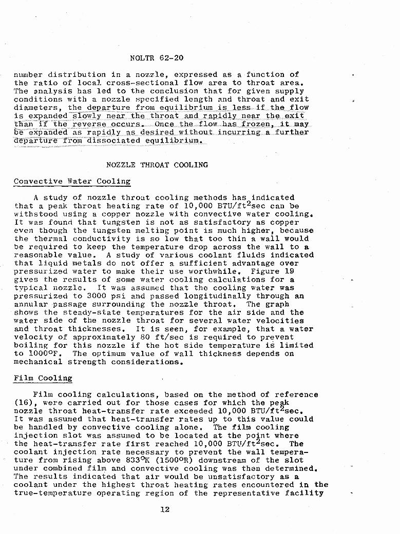
number distribution in a nozzle, expressed as a function of the ratio of local cross-sectional flow area to throat area. The analysis has led to the conclusion that for given supply conditions with a nozzle specified length and throat and exit diameters, the departure from equilibrium is less if the flow is expanded "slowly near the throat and rapidly near the exit than if the reverse occurs* Once the flow has frozen,it may Be"expanded as rapidly as desired, without incurring a further departure from dissociated equilibrium.
NOZZLE THROAT COOLING
Convective Water Cooling
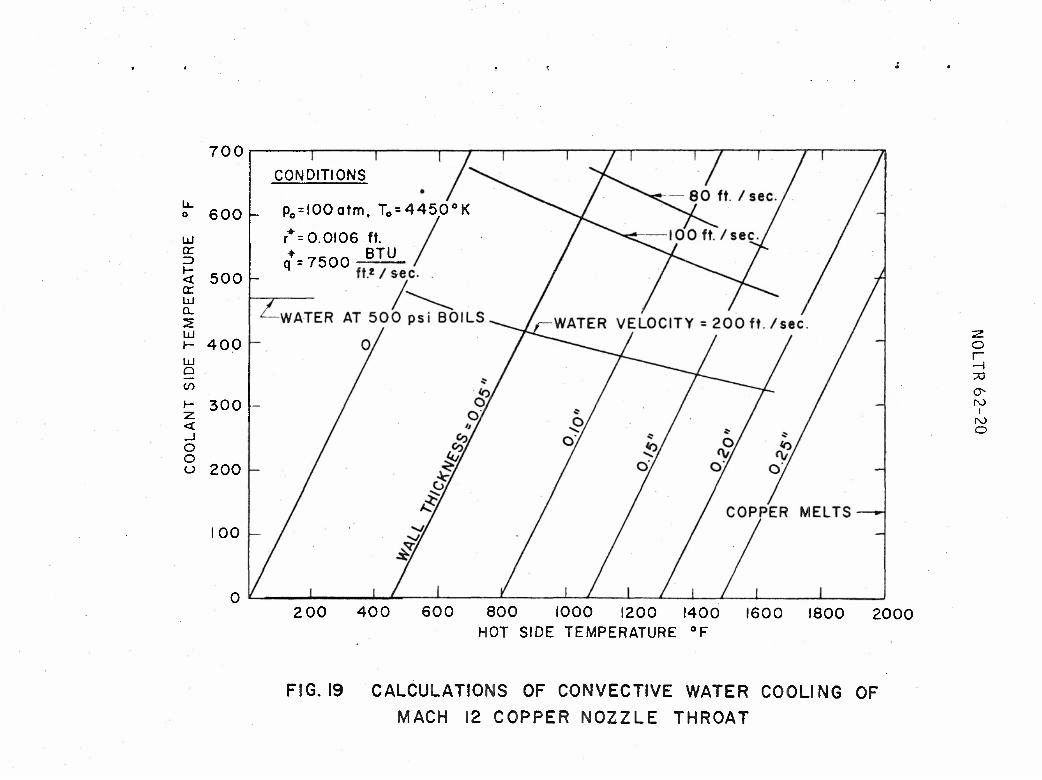
A study of nozzle throat cooling methods has indicated that a peak throat heating rate of 10,000 BTU/ft^sec can be withstood using a copper nozzle with convective water coolings It was found that tungsten is not as satisfactory as copper even though the tungsten melting point is much higher, because the thermal conductivity is so low that too thin a wall would be required to keep the temperature drop across the wall to a reasonable value. A study of various coolant fluids indicated that liquid metals do not offer a sufficient advantage over pressurized water to make their use worthwhile. Figure 19 gives the results of some water cooling calculations for a typica.«. nozzle. It was assumed that the cooling water was pressurized to 3000 psi and passed longitudinally through an annular passage surrounding the nozzle throat. The graph shows the steady-state temperatures for the air side and the water side of the nozzle throat for several water velocities and throat thicknesses. It is seen, for example, that a water velocity of approximately 80 ft/sec is required to prevent boiling for this nozzle if the hot side temperature is limited to 1000°F. The optimum value of wall thickness depends on mechanical strength considerations.
Film Cooling
Film cooling calculations, based on the method of reference (16), were carried out for those cases for which the peak nozzle throat heat-transfer rate exceeded 10,000 BTU/ft^sec. It was assumed that heat-transfer rates up to this value could be handled by convective cooling alone. The film cooling injection slot was assumed to be located at the point where the heat-transfer rate first reached 10,000 BTU/ft2sec. The coolant injection rate necessary to prevent the wall tempera- ture from rising above 833°K (1500°R) downstream of the slot under combined film and convective cooling was then determined. The results indicated that air would be unsatisfactory as a coolant under the highest throat heating rates encountered in the true-temperature operating region of the representative facility
12

NOLTR 62-20
as shown In figure 14, because the required injection rates would be of the same order of magnitude as the normal mass flow rate through the nozzle. Helium has no advantage over air for this application since its heat capacity per unit volume is essentially the same as that of air» The calcu- lations showed, however, that if water was employed, the injection of 12 percent by weight of fluid would cool the throat of a Mach 15 nozzle operating with a supply pressure of 500 atmospheres and a supply temperature of 5000°K. The peak throat heat-transfer rate without film cooling for this case was calculated to be 29,000 BTU/ft2sec.
The operating limitations imposed by the throat-cooling problem on the wind tunnel discussed in this report are shown for true-temperature and condensation-threshold operation in figures 20 and 21, respectively. Convectively cooled nozzles would allow operation up to about Mach 12,5 in the former case and to about Mach 19 in the latter. To operate at a higher Mach number in either case, film cooling would be required,,
THE HYPERVELOCITY DIFFUSER AND PUMPING SYSTEM
The Diffuser
The hypervelocity diffuser is an important element in the wind-tunnel system since it converts the momentum of the high speed, low pressure jet in the test section to a low speed flow with a higher pressure, thereby allowing a great reduction in the size and cost of the pumping plant. The flow in the diffuser is quite complex, so that it is easiest to analyze the problem by applying the equations of continuity, momentum, and energy to the air entering and leaving the diffuser, without inquiring into the details of the internal flow. Calculations were carried out over a wide range of conditions for diffusers consisting of a straight duct, 30 feet long, of the same diameter as the nozzle exit. The following approxi- mations were made: (a) the heat transfer losses to the diffuser wall are small enough so that the total enthalpy of the flow remains constant; (b) the boundary-layer displacement thickness and momentum thickness at the diffuser exit are zero; (c) the friction force along the diffuser duct may be estimated by using the average of the values at the nozzle exit and dif- fuser exit. The flow conditions at the end of the diffuser were found by an iterative procedure using the 3 conservation equations, a low speed turbulent pipe flow formula for the friction at the exit of the diffuser, and a Mollier chart for high-temperature air. A first approximation to the recovery pressure P2 may be obtained by neglecting the friction force and the momentum of the flow at the diffuser exit, and by assuming that the recovery pressure is much larger than the
13

NOLTR 62-20
static pressure pe at the nozzle exit. The resulting equation is
P2 . Xu 2 Ae (3) A
where o is the ratio of specific heats, Me is the test section Mach number, Ae is the nozzle exit isentropic core area, and A is the total nozzle exit area including the boundary-layer correction. It was found that the above equation gave a recovery pressure about 10 percent higher than the final solution in most cases. This equation shows that the diffuser recovery pressure is determined mainly by the thickness of the boundary layer at the nozzle exit.
The diffuser recovery pressure and temperature are shown for true-temperature operation in figure 3 and for condensation- threshold operation in figure 5. It may be noted that the dif- fuser recovery temperature is considerably lower than the nozzle supply temperature. This is so because the air at the rela- tively low recovery pressure is more highly dissociated, so that a greater portion of the total energy is being stored as the chemical energy of dissocation, and less is in the form of the translational energy of random motion of the molecules, which manifests itself as temperature. In the tunnel under study, the minimum operating pressure of 5 mm Hg for the pumping plant sets the boundary for high altitude operation.
Pumping Requirements
After leaving the diffuser, the air is passed through an aftercooler where the air temperature is reduced to ambient conditions before entering the vacuum pumps«, The curves of volumetric pumping speed, shown in figures 14 and 15, were computed from a knowledge of the mass flow, assuming that the air enters the pumps at the diffuser recovery pressure and a temperature of 70°F. If the pressure losses in the aftercooler are not negligible as assumed here, then the required pumping speed will have to be increased by approximately the same per- centage as the diffuser recovery pressure exceeds the inlet pressure to the pumps.
CONCLUSIONS
The simulation of re-entry conditions in a continuous, hypervelocity wind tunnel has been investigated in detail* The testing requirements are much more stringent than at low supersonic speeds since in order to duplicate the chemical effects occurring at high temperature, not only the Mach
14

NOLTR 62-20
number but also the static pressure and temperature of the air in the test section must correspond to free flight.
The very high nozzle supply temperatures required can be generated using an electric arc A direct current arc is preferable to an alternating current device in order to avoid fluctuations in the flow. An analysis of the problem of cooling the arc electrodes and the arc chamber indicates that it should be possible to operate arcs at a pressure of several hundred atmospheres.
The requirement for excessive supply pressures at high Mach number places a limit on the maximum Mach number at which true-temperature operation is possible. For a maximum supply pressure of 500 atmospheres, this limit was found to be Mach 14 when simulating an altitude of 200,000 feet, and less than Mach 10 at a static pressure corresponding to 100,000 feet.
Operation may be extended to Mach 20 if the air is only heated sufficiently to avoid condensation in the test section. For such a partial simulation, nitrogen would be as satis- factory as air and the use of nitrogen would allow the graphite resistance heater, capable of operating up to a pressure of 1000 atmospheres, to be employed. Very high velocities (but low Mach numbers) may be obtained with moderate supply pres- sures by strongly overheating the air. This type of operation is not desirable for aerodynamic testing because it results in "frozen flow," with air rich in oxygen atoms in the test section.
As a part of the analysis, methods were developed for designing contoured axially symmetric nozzles with a turbu- lent boundary-layer correction for high-temperature air in dissociated equilibrium, A study of throat cooling techniques indicated that convective water cooling should be possible for heat-transfer rates up to 10,000 BTU/ft^sec In practice, this means that convective cooling is possible with true- temperature nozzles operating up to about Mach 12. At higher Mach numbers, water film cooling should be feasible.
A study of the effect of a finite oxygen recombination rate in nozzles indicated that if the flow is expanded to low temperatures, it will freeze in a mixture rich in oxygen atoms in all cases. However, for a wide range of test conditions, the fraction of oxygen frozen in atomic form and the resulting departure from equilibrium is small.
As an example of the application of the results, the operating boundaries of a representative hypervelocity wind tunnel are presented. For this facility, the simulation covers a range of altitudes from a little below 150,000 feet to somewhat over 200,000 feet with true temperatures up to
15

NOLTR 62-20
nearly Mach 15, and condensation-free operation to Mach 20. The test section static pressure ranges from about 0.07 mm Hg to 2 mm Hg. Calculations indicate that a hypervelocity dif- fuser would be effective in recovering a pressure of 5 mm Hg or higher, allowing a conventional mechanical pumping system to be used, The diffuser efficiency is governed mainly by the boundary-layer thickness at the nozzle exit. Altitudes above 220,000 feet could be simulated by using a high vacuum pumping system. With sufficient air heating power, an altitude as low as 100,000 feet could be simulated up to Mach 10, but the problems of nozzle and arc chamber heating tend to be very severe even at low Mach numbers.
It may be concluded that the continuously operating hyper- velocity wind tunnel has a capability of simulating a wide range of re-entry conditions. Like any other facility, it is, however, subject to certain fairly well defined operating limitations, as discussed in this report»
16

NOLTR 62-20
REFERENCES
(1) Enkenhus, K. R., "The Flight Environment of Long Range Ballistic Missiles and Glide Vehicles," NAVORD Report 6745, October 1959
(2) Korobkin, I» and Hastings, S. M„, "Mollier Chart for Air in Dissociated Equilibrium at Temperatures of 2000°K to 15,000°K," NAVORD Report 4446, May 1957
(3) Wegener, P., Stollenwerk, E., Reed, S„, and Lundquist, G., "NOL Hyperballistics Tunnel No. 4 Results I: Air Lique- faction," NAVORD Report 1742, January 1951
(4) Cobine, J. D., "Gaseous Conductors - Theory and Engineering Applications," Dover Publications, New York
(5) Finkelburg, W. F. and Maecher, H0, "Electric Arcs and Thermal Plasma," Langley Research Center Translation, October 1958
(6) Jedlicka, J. R., "The Development of Electric Arcs at the Ames Research Center," paper presented at the Ü, S, Naval Ordnance Laboratory, White Oak, Maryland, 15 June 1960
(7) A Symposium on the Electric Arc, Westinghouse Corporation, Pittsburg, Pennsylvania, 20-22 September 1960
(8) G, E. Technical Proposal, "Advanced Facility Requirements for Simulation of Re-entry Conditions," Document No„ 595D6, 1 April 1959
(9) Rose, P., Powers, W., and Hritzay, D„, "The Large High Pressure Arc Plasma Generator: A Facility for Simulating Missile and Satellite Re-entry," AVCO Research Report No. 56, June 1959
(10) Kivel, B. and Bailey, K., "Tables of Radiation from High Temperature Air," AVCO Research Report No« 21, January 1958
(11) Hilsenrath, J, and Beckett, C. W., "Tables of Thermodynamic Properties of Argon-Free Air to 15,000°K," AEDC-TN-56-12, September 1956 and Addendum thereto (undated)
(12) Hansen, C. F,, "Approximations for the Thermodynamic and Transport Properties of High Temperature Air," NACA TN 4150, March 1958
(13) Rose, P. H., Probstein, R. F., and Adams, M. C, "Turbu- lent Heat Transfer Through a Highly Cooled, Partially Dissociated Boundary Layer," AVCO Research Report No. 14, January 1958
(14) Heims, S. P., "Effect of Oxygen Recombination on One- Dimensional Flow at High Mach Numbers," NACA TN 4144, 1958
(15) Camac, M. and Vaughan, A«, "Oxygen Vibration and Dis- sociation Rates in Oxygen-Argon Mixtures," AVCO Research Report No. 84, December 1959
(16) Tribus, M. and Kline, J„, "Forced Convection From Non- Isothermal Surfaces," Heat Transfer Symposium, University of Michigan, pp. 211-233, 1955
17

NOLTR 62-20
300
200 o
H
a
t < 100
/5Ö
•PRESENT N.O.L CAPABILITIES
0 10 15
MACH NUMBER
20 25
FIG. I COMPARISON OF FLIGHT CORRIDORS OF RE-ENTRY VEHICLES WITH PRESENT N.O.L. WIND
TUNNEL SIMULATION CAPABILITIES

NOLTR 62-20
2000
SUPPLY ENTHALPY (BTU/L8)
3000 4000 5000 6000
.01
.02
2 5
.03 -
.04
.05 —
.08 -
Q- 0.2 —
fc 0.3
04 —
05 0.6
0.8
1.0
2.0
250
200
150
12 14
MACH NUMBER
FIG.2 TRUE TEMPERATURE OPERATING PARAMETERS MASS FLOW, MAXIMUM RUNNING TIME,
SUPPLY TEMPERATURE AND SUPPLY PRESSURE

NOLTR 62-20
2000 SUPPLY ENTHALPY (BTU/LB)
3000 4000 5000
•150
MACH NUMBER
FIG.3 TRUE TEMPERATURE OPERATING PARAMETERS AIR HEATING POWER, DIFFUSER RECOVERY PRESSURE
AND DIFFUSER RECOVERY TEMPERATURE

NOLTR 62-20
MACH NUMBER
FIG. 4k CONDENSATION THRESHOLD OPERATING PARAMETERS MASS FLOW, MAXIMUM RUNNING TIME,
SUPPLY TEMPERATURE AND SUPPLY PRESSURE

NOLTR 62-20
>
t200 §
150
MACH NUMBER
FIG. a CONDENSATION THRESHOLD OPERATING PARAMETERS AIR HEATING POWER, DIFFUSER RECOVERY PRESSURE AND TEMPERATURE

NOLTR 62-20
1000
CO ÜJ er ÜJ x Q_ to O
UJ tr to to UJ (T
z
!* CE UJ OL O
100
10
' LEGEND ' ' ' . 1
- O G.E. 100 KW (WATER STABILIZED) A G.E. 100 KW (SHROUDED AIR ARC)
- Q AVCO 150 KW . V AVCO 1400 KW
O WESTINGHOUSE 590 KW (N2) - A G.E. 750 KW
k AMES WINOVICH ARC 900 KW k.
-
A
o
—
-
_ . 1
A -
Ql 1 1 1 1 1
1956 1957 1958 1959
YEAR
I960 1961 1962
FIG. 6 DEVELOPMENT OF D.C. ELECTRIC ARCS FOR WIND TUNNEL APPLICATION

NOLTR 62-20
14
MACH NUMBER
FIG. 7 ARC DEVELOPMENT ON A TRUE TEMPERATURE
OPERATING REQUIREMENTS DIAGRAM
NOLTR 62-20
WATER
+ ELECTRODE
WATER
WATER
/ \ ^ -tV
y////
WA
WATER
FIG. 8 GEOMETRY OF A D.C. ELECTRIC ARC

NOLTR 62-20
X
2 5
UJ IE
m in UJ <r 0.
4 i-
2000
SUPPLY ENTHALPY
3000
(BTU/LB)
4000 5000 6000
Z^> 250
~> 150 _-
12 14
MACH NUMBER
16 IS
FIG. 9 ELECTRIC ARC CHARACTERISTICS FOR TRUE TEMPERATURE OPERATION
MAXIMUM PERMISSIBLE ARC CURRENT AND CORRESPONDING VOLTAGE REQUIRED TO GENERATE POWER AT 33% EFFICIENCY FOR 2 SQUARE FOOT JET

NOLTR 62-20
MACH NUMBER
FIG. 10 ELECTRIC ARC CHARACTERISTICS FOR CONDENSATION THRESHOLD OPERATION
MAXIMUM PERMISSIBLE ARC CURRENT AND CORRESPONDING VOLTAGE REQUIRED
TO GENERATE POWER AT 33 % EFFICIENCY FOR 2 SQUARE FOOT JET
NOLTR 62-20
10
o id w
W
id
CC Id U_ </)
<
5•
< Id
10"
10
10
RADIATION
CONVECTION
1000 2000 3000 4000 5000 6000
TEMPERATURE (°K)
FIG. II RADIATIVE AND GONVECTIVE HEAT TRANSFER TO ARC CHAMBER
TRUE TEMPERATURE OPERATION

NOLTR 62-20
-NOZZLE WALL UNIFORM FLOW
r«
rr
ISENTROPIC CORE BEFORE BOUNDARY
LAYER CORRECTION
FIG. 12 Ä MACH 15 NOZZLE DESIGNED FDR A PRESSURE OF 500 ATM. AND A SUPPLY
TEMPERATURE OF 6000° K
SUPPLY

NOLTR 62-20
T0= 2500*K
Tw* 8308K
O
to eg
£ IO'
I0!
p0 = 500 ATM.
p =200 ATM.
-.2 .8
X (FT)
FIG. 13 THROAT REGION HEAT TRANSFER VARIATION WITH MACH NO. (M),SUPPLY PRESSURE (p0)
FOR GIVEN SUPPLY TEMPERATURE (T0) AND NOZZLE.
WALL TEMPERATURE (Tw)

NOLTR 62-20
s
01
02
03
.04
.05
.06
0.1
02 u
< « 0.3
0.5 0.6
oe
i o
2.0
2000
SUPPLY ENTHALPY (BTU/LB)
3000 4000 5000 6000
250
12 14
MACH NUMBER
"• ZOO
< tn 3 O
150
FIG. 14 TRUE TEMPERATURE OPERATING PARAMETERS PEAK NOZZLE THROAT CONVECTIVE AND RADIATIVE HEAT TRANSFER RATES,
PUMPING SPEED AND BOUNDARY LAYER DISPLACEMENT THICKNESS
AT NOZZLE EXIT

NOLTR 62-20
•250
>200$
• 150
MACH NUMBER
FIG. 15 CONDENSATION THRESHOLD OPERATING PARAMETERS PEAK NOZZLE THROAT CONVECTIVE HEAT TRANSFER RATE (RADIATION NEGLIGIBLE), PUMPING SPEED AND BOUNDARY
LAYER DISPLACEMENT THICKNESS AT NOZZLE EXIT

NOLTR 62-20
1 SUPPLY CONDITIONS 1 1 | | | |i
V-—- 5000° K- 10 ATM- -
ZE -
et o V*OL_ 5000° K-50 ATM. _ u.
o 2 o 1-
—\ \ \ NON-EQUILIBRIUM - <
z
— \ \
5000° K-200 ATM.
co 10""
o 1- <
-
z o 5000°K-500ATM- >- X O -
o 1 -
§ \
•- o io-g
or —
i
1 EQUILIBRIUM
III 1 1 1 I 5 7 9
MACH NUMBER II 13
FIG. 16 OXYGEN RECOMBINATION IN A CONICAL MACH 15 NOZZLE (PARABOLIC THROAT, 6FT. LENGTH)

NOLTR 62-20
o u.
2 O
10 -i
M O
2 LU (D >- X o
g lo H O < a:
-e
i—r
j_L
1 1 1—[ 1 1 1 r~
SUPPLY TEMPERATURE
i i i
10 100 SUPPLY PRESSURE (ATM.)
6000° K
5000°K
4000° K
1000
FIG. 17 FRACTION OF OXYGEN BY WEIGHT WHICH FREEZES IN A MACH 15 CONICAL NOZZLE
(PARABOLIC THROAT, 6 FT LENGTH)

NOLTR 62-20
GG UJ m S
X O <
15
I I
SUPPLY CONDITIONS
TEMPERATURE- 5000» K PRESSURE -10 ATM.
10 10' I04 10"
AREA RATIO
FIG. 18 EFFECT OF FINITE OXYGEN RECOMBINATION RATE ON MÄCH NUMBER OBTAINED IN A MACH 15 CONICAL NOZZLE
(PARABOLIC THROAT, 6 FT. LENGTH )
o
er Z)
<
m a.
UJ J- UJ Q
CO
700
600
500
400
CONDITIONS
_ pe = IOOatm, To=4450°K
r* = 0.0106 ft. • ,K• BTU q = 7500
s- 300 -
o o o 200
00
o r~ —i 73
O- ro
i
ro o
200 400 600 800 1000 1200 1400 1600 1800 2000 HOT SIDE TEMPERATURE °F
FIG. 19 CALCULATIONS OF CONVECTiVE WATER COOLING OF MACH 12 COPPER NOZZLE THROAT

01
.02
2.0
NOLTR 62-20
2000
SUPPLY ENTHALPY (BTU/LB)
3000 4000 5000 6000
250
o z •a <n
«200 2
150
10 12 14 16 18
MACH NUMBER
FIG. 20 TRUE TEMPERATURE OPERATING BOUNDARIES 2 SQUARE FOOT JET AT NOZZLE EXIT WITH 400° R STATIC TEMPERATURE

NOLTR 62-20
.04
.03
OS
aFFUSERSSWI5iLWIs-SyRE"-5 **•-**•
• M&SS FLO* r^t^s£C
CONVECTIVELY COOLED NOZZLES
_ .^FILM COOLED.. / NOZZLES s'
10 *• I 1 I J L
MACH NUMBER
FIG. Z\ CONDENSATION THRESHOLD OPERATING BOUNDARIES 2 SQUARE FOOT JET AT NOZZLE EXIT