Embed Size (px)
Citation preview

Met One Instruments, Inc
1600 Washington Blvd.
Grants Pass, Oregon 97526 Telephone 541-471-7111 Facsimile 541-471-7116
Regional Service 3206 Main St. Suite 106 Rowlett, Texas 75088 Telephone 972-412-4715 Facsimile 972-412-4716
AEROCET 531S MANUAL

AEROCET 531S Manual Rev F Page 2
Copyright Notice AEROCET 531S Manual © Copyright 2014 Met One Instruments, Inc. All Rights Reserved Worldwide. No part of this publication may be reproduced, transmitted, transcribed, stored in a retrieval system, or translated into any other language in any form by any means without the express written permission of Met One Instruments, Inc.
Technical Support
This manual is structured by customer feedback to provide the required information for setup, operation, testing, maintaining, and troubleshooting your GT-521S. Should you still require support after consulting your printed documentation, we encourage you to contact one of our expert Technical Service representatives during normal business hours of 7:00 a.m. to 4:00 p.m. Pacific Standard Time, Monday through Friday. In addition, technical information and service bulletins are often posted on our website. Please contact us and obtain a Return Authorization (RA) number before sending any equipment back to the factory. This allows us to track and schedule service work and to expedite customer service. Please have your instrument serial number available when contacting the manufacturer. Contact Information:
Tel: + 541 471 7111 Fax: + 541 471 7115 Web: http:/www.metone.com Email: [email protected]
Address: Met One Instruments, Inc. 1600 Washington Blvd Grants Pass, Oregon 97526 U.S.A.
NOTICE
CAUTION—Use of controls or adjustments or performance of procedures other than those specified herein may result in hazardous radiation exposure.
WARNING—This product, when properly installed and operated, is considered a Class I laser product. Class I products are not considered to be hazardous.
There are no user serviceable parts located inside the cover of this device.
Do not attempt to remove the cover of this product. Failure to comply with this instruction could cause accidental exposure to laser radiation.

AEROCET 531S Manual Rev F Page 3
Table of Contents
1. Introduction ........................................................................................................... 5
2. Setup ...................................................................................................................... 5
2.1. Unpacking .................................................................................................................................. 5
2.2. Layout ........................................................................................................................................ 8
2.3. Default Settings ......................................................................................................................... 9
2.4. Initial Operation ......................................................................................................................... 9
3. User Interface ........................................................................................................ 9
4. Operation ............................................................................................................. 10
4.1. What’s New and Different ........................................................................................................ 10
4.2. About the Measurement .......................................................................................................... 10
4.3. Power Up ................................................................................................................................. 10
4.4. Operate Screen ....................................................................................................................... 11
4.4.1. Sampling ........................................................................................................................... 12
4.4.2. Sample Status ................................................................................................................... 12
4.4.3. Sample History .................................................................................................................. 12
4.4.4. Warning / Error Messages ................................................................................................ 13
4.5. Sample Related Functions ...................................................................................................... 13
4.5.1. Starting/Stopping ............................................................................................................... 13
4.5.2. Measurement Type ........................................................................................................... 13
4.5.3. Sample Mode .................................................................................................................... 13
4.5.4. Hold Time .......................................................................................................................... 13
4.5.5. Real-Time Serial Report ................................................................................................... 13
4.5.6. Sample Timing .................................................................................................................. 14
5. Menu Selections .................................................................................................. 14
5.1. Edit Menu Items ....................................................................................................................... 15
5.2. Sample Setup Screen .............................................................................................................. 15
5.2.1. Location Number ............................................................................................................... 15
5.2.2. Measure ............................................................................................................................ 15
5.2.3. Sample Mode .................................................................................................................... 16
5.2.4. Hold Time .......................................................................................................................... 16
5.3. Settings Screen ....................................................................................................................... 16
5.3.1. Volume .............................................................................................................................. 16
5.3.2. Temperature ...................................................................................................................... 16
5.3.3. Sensitivity .......................................................................................................................... 16
5.4. Serial Screen ........................................................................................................................... 17
5.4.1. Report ............................................................................................................................... 17
5.4.2. Baud Rate ......................................................................................................................... 17
5.4.3. Serial ................................................................................................................................. 17
5.5. Recall Data Screen .................................................................................................................. 18
5.6. Print Data Screen .................................................................................................................... 18

AEROCET 531S Manual Rev F Page 4
5.7. Memory Screen ....................................................................................................................... 19
5.7.1. View Available Memory ..................................................................................................... 19
5.7.2. Clearing Memory ............................................................................................................... 19
5.8. Set Flow Screen ...................................................................................................................... 20
5.9. Set Clock Screen ..................................................................................................................... 20
5.10. Set Contrast Screen ................................................................................................................ 21
5.11. About Screen ........................................................................................................................... 21
6. Charging the Battery ........................................................................................... 21
7. Serial Communications ...................................................................................... 22
7.1. Serial Interface ........................................................................................................................ 23
7.2. Commands .............................................................................................................................. 24
7.3. Real Time Output .................................................................................................................... 25
7.4. Comma Separated Value (CSV) ............................................................................................. 26
7.4.1. Counts Format .................................................................................................................. 26
7.4.2. Mass Format ..................................................................................................................... 27
7.5. Printer Format .......................................................................................................................... 28
7.5.1. Counts Format .................................................................................................................. 28
7.5.2. Mass Format ..................................................................................................................... 28
8. Maintenance ........................................................................................................ 28
8.1. Service Schedule ..................................................................................................................... 28
8.2. Zero Count Test ....................................................................................................................... 29
8.3. Flow Rate Test......................................................................................................................... 29
8.4. Annual Calibration ................................................................................................................... 29
8.5. Flash Upgrade ......................................................................................................................... 29
9. Troubleshooting .................................................................................................. 30
10. Specifications ...................................................................................................... 31
11. Warranty / Service ............................................................................................... 32
AEROCET 531S Manual Rev F Page 5
1. Introduction
The AEROCET 531S is a full–featured, battery operated, handheld particle counter or mass monitor.
In count mode, the unit will measure particle counts at four fixed sizes (0.5µm, 1.0µm, 5.0µm, and 10.0µm) when set to low sensitivity and five fixed sizes (0.3µm, 0.5µm, 1.0µm, 5.0µm, and 10.0µm) when set to high sensitivity (See Section 5.3.3 for more detail).
In mass mode the unit will measure PM1, PM2.5, PM4, PM7, PM10 and TSP mass concentration levels.
This instrument can store up to 6,000 sample events including data from the optional ambient temperature (AT) / relative humidity (RH) probe (PN G3120). Sample history events can be viewed on the LCD display, printed on the optional printer (PN G3115) and download to a computer.
2. Setup
The following sections cover unpacking, layout and performing a test run to verify operation.
2.1. Unpacking
Unpack and inspect the contents of the shipping container. Standard items (included) are shown in Figure 1 – Standard Accessories. Optional accessories are shown in Figure 2 – Optional Accessories. Contact the supplier if any items are missing. Any damages incurred to the equipment during shipping are the responsibility of the carrier. If any damage to the shipment is noticed before unpacking, a claim must be filed with the commercial carrier immediately. You should follow any special unpacking instructions provided by the carrier as you then carefully remove all items from the containers and inspect each component. It is recommended to document and photograph all damaged packages and items before, during, and after unpacking them. Contact Met One Instruments (see the Technical Support section at the beginning of this manual) to arrange for any replacement items needed.

AEROCET 531S Manual Rev F Page 6
ATTENTION: The included USB drivers must be installed before connecting the AEROCET 531S USB port to your computer. If the supplied drivers are not installed first, Windows may install generic drivers that are not compatible with this product. To install USB drivers: Insert the Comet CD. The install program should run automatically and display the screen below. If an AutoPlay pop-up window appears, select “Run AutoRun.exe”. Finally, select “USB Drivers” to start the install process. You may be prompted to re-boot your computer when the driver installation is complete.
Note: For proper communication, set the virtual COM port baud rate to 9600 32 Bit Operating Systems should install the 32 bit USB drivers. 64 Bit Operating Systems should install the 64 bit USB drivers.

AEROCET 531S Manual Rev F Page 7
Figure 1 – Standard Accessories
Printer PN G3115
Flow Meter PN 9801
Serial Cable PN 3228
T/RH Probe PN G3120
Figure 2 – Optional Accessories
AEROCET 531S Standard Equipment
AEROCET 531S PN AEROCET-531S
Battery Charger PN 390031
Power Cord PN 400113
Carrying Case PN 8517
Calibration Certificate AEROCET-531S-9600
ISO-Kinetic Probe PN G3110
Zero Count Filter PN G3111
USB Cable PN 500787
Comet Software CD
PN 80248
Manual
AEROCET-531S-9800 PN PN
AEROCET 531S Manual Rev F Page 8
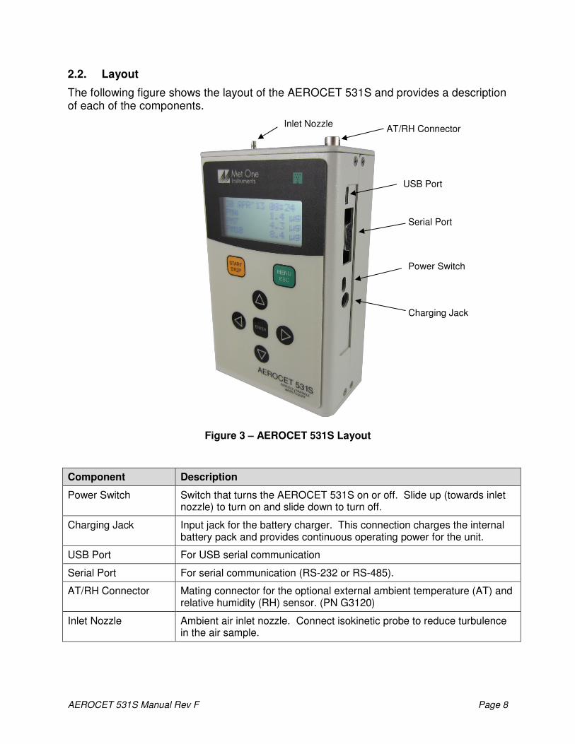
2.2. Layout
The following figure shows the layout of the AEROCET 531S and provides a description of each of the components.
Figure 3 – AEROCET 531S Layout
Component Description
Power Switch Switch that turns the AEROCET 531S on or off. Slide up (towards inlet nozzle) to turn on and slide down to turn off.
Charging Jack Input jack for the battery charger. This connection charges the internal battery pack and provides continuous operating power for the unit.
USB Port For USB serial communication
Serial Port For serial communication (RS-232 or RS-485).
AT/RH Connector Mating connector for the optional external ambient temperature (AT) and relative humidity (RH) sensor. (PN G3120)
Inlet Nozzle Ambient air inlet nozzle. Connect isokinetic probe to reduce turbulence in the air sample.
Charging Jack
Inlet Nozzle AT/RH Connector
USB Port
Serial Port
Power Switch

AEROCET 531S Manual Rev F Page 9
2.3. Default Settings
The AEROCET 531S comes with the user settings configured as follows.
Parameter Value
Sample Location 1 Sample Type Mass (µg/m3) Sensitivity High Sample Mode Manual Sample Hold Time 0 seconds Volume (concentration) CF (particles / ft3) Temperature Units C Baud Rate 9600 Serial Mode RS-232
2.4. Initial Operation
Before operating the AEROCET 531S for the first time, it is recommended that the unit be fully charged. Information regarding charging the battery is found in section 6 of this manual.
Complete the following steps to verify proper operation. 1. Slide the power switch up to turn on the power. 2. Observe the Startup screen for 3 seconds then the Operate screen (Section 4.4) 3. Press START/STOP key. The AEROCET 531S will sample for 1 minute and stop. 4. Observe the PM levels on the display 5. Use the up / down arrows to view other PM levels 6. The unit is ready for use
3. User Interface
The AEROCET 531S user interface is composed of a 7 button keypad and a LCD display. The following table describes keypad functionality. Note some keys have more than one function.
Key Description
• Starts or stops a sample.
• Starts the unit printing when in the PRINT DATA screen.
• Recalls the selected data when in the RECALL DATA screen.
• Loads the Menu screen when not in edit mode.
• Loads the Operate screen when in the Menu screen.
• Cancel edit mode and return the field to the original value.
• Loads the screen associated with menu item.
• Begins editing of the selected item.
• Stops editing a field and saves the changed value.
• Scroll sizes (Operate screen)
• Navigates up/down when not editing (Menu).
• Modifies field when editing.
• Navigates right / left
• Move through history buffer (Operate screen)
MENU
ESC
ENTER
STOP
START

AEROCET 531S Manual Rev F Page 10
4. Operation
The following sections cover the basic operation.
4.1. What’s New and Different
You should be aware of key differences between the AEROCET 531S and 531.
Description 531S 531 Comments
Sensitivity High / Low 0.5µm 0.3µm = High, 0.5µm = Low
Mass Concentration Units µg/m3 mg/m
3
Mass Concentration Precision 0.1 µg /m3 0.001 mg/m
3 Higher precision
Sample Time 1-minute 2-minutes Faster sample time
Hold Time Units Seconds Minutes Shorter hold times
Contrast Adjust Software Mechanical No tools required. See Section 5.10
Battery Lithium-ion NiMh Warning: See Section 6
4.2. About the Measurement
The AEROCET 531S counts and sizes particles in 8 different size ranges then uses a proprietary algorithm to convert count data to mass measurements (µg/m3). Fundamentally, the AEROCET 531S calculates a volume for each detected particle then assigns a standard density for the conversion.
The standard density value is augmented by the K-Factor setting to improve measurement accuracy. The AEROCET 531S provides a separate K-Factor setting for each measurement range (PM1, PM2.5, PM4, PM 7, PM10, and TSP). These K-Factors can be modified with Comet software or with the SK serial port command.
K-Factor values should be empirically derived via comparison with a reference unit. If a reference unit is unavailable, the recommended K-Factor setting is 3.0.
4.3. Power Up
AEROCET 531S power is controlled by a slide switch located on the right hand side of the unit. Move the power switch to the on position (towards the top of the case) to power up the unit.
The first screen shown on power up is the Startup screen (Figure 4). This screen displays the product type and company website for 2 seconds before loading the Operate Screen.
AEROCET 531S
WWW.METONE.COM
Figure 4 – Startup Screen

AEROCET 531S Manual Rev F Page 11
4.4. Operate Screen
The Operate screen can display the count or mass measurement. It is determined by the MEASURE setting. The Operate screen displays the date and time, sample status, current sample data and previous sample data. Figure 5 and Figure 6 shows the Mass and Count screens.
When sampling in mass mode, the size selection represents the upper threshold of your sample. For example, when you read the value for PM10 it contains all mass that is size PM10 and lower. Conversely, when sampling in count mode, the size selections represent the lower threshold of your sample. An example would be that the 1.0u size contains all particulate that are 1.0u and larger.
22 JAN’13 17:56
PM1 1.1 ug
PM2.5 3.3 ug
PM4 4.6 ug
PM7 5.5 ug
PM10 6.7 ug
TSP 10.6 ug
AT 21 C
RH 45 %
LOCATION 001
Figure 5 – Mass Operate Screen with AT and RH
22 JAN’13 17:56
0.5u 24,600 TC
1.0u 2,516 TC
5.0u 44 TC
10 u 21 TC
AT 21 C
RH 45 %
LOCATION 001
Figure 6 – Count Operate Screen with AT and RH
The top line of the Operate screen is reserved for the normal header (date and time) or status/alarm messages depending upon the machine status. The top line remains stationary while the other 3 lines scroll to display the full list. AT and RH data will precede the location number when the AT/RH probe is attached.
Ambient temperature (AT) can be displayed in units of Celsius (C) or Fahrenheit (F).

AEROCET 531S Manual Rev F Page 12
4.4.1. Sampling
The Operate screen displays current sample information when the unit is sampling (real time data). Concentration values (ug/m3) are time dependent so these values may fluctuate early in the sample; however, after several seconds the measurement will stabilize. Figure 7 shows the Operate screen while sampling.
█ 58
PM1 0.0 ug
PM2.5 0.0 ug
PM4 0.0 ug
Figure 7 – Operate Screen Sampling
4.4.2. Sample Status
The top line of the Operate screen displays the status of the AEROCET 531S while the unit is sampling. The following table shows the various status messages:
Status Description
STARTING... AEROCET 531S is starting the sample and is waiting for the count system to initialize.
HOLDING... AEROCET 531S is in auto mode and is waiting for the hold time to finish.
STOPPING... AEROCET 531S is stopping the sample and is waiting for the count system to stop.
█ █ █ █ █ █ 10 AEROCET 531S is sampling. The progress bar moves from left to right as the sample progresses. The time remaining is displayed to the far right.
4.4.3. Sample History
Sample history (previous data) can be viewed on the Operate screen when the unit is stopped (not sampling). To view sample history, press the ENTER key or ◄ from the Operate screen. The unit will display the last sample event (newest record) and display “←←←←” in the upper right corner of the display (see Figure 8) to indicate history data. Press ◄ or ► to move through sample history one record at a time (◄ displays older events, ► displays newer events). Press the ENTER key at any time to return to the Operate screen. Press START at any time to start a new sample.
03 DEC’12 11:23←←←←
PM1 0.0 ug
PM2.5 0.0 ug
PM4 0.0 ug
Figure 8 – History Screen

AEROCET 531S Manual Rev F Page 13
4.4.4. Warning / Error Messages
The AEROCET 531S displays warning/error messages on the top line of the Operate screen. These messages alternate with the normal date/time header. The following table lists the warning/error messages:
Display Message Description
LOW BATTERY! Low battery warning. Less than 15 minutes of normal operation remaining.
SENSOR ERROR! Particle sensor error.
4.5. Sample Related Functions
The following sub-sections cover sample related functions.
4.5.1. Starting/Stopping
To start or stop a sample, press the START/STOP key. A sample event can be manually started or stopped from either the Operate screen or the menu.
4.5.2. Measurement Type
The measurement type determines if the instrument measure mass (ug/m3) or particle concentration (particles/volume). Measurement type is discussed in section 5.2.
4.5.3. Sample Mode
The sample mode controls single sample or continuous sampling. The MANUAL setting
configures the unit for a single sample. The AUTO setting configures the unit for continuous sampling. Sample modes are discussed in section 5.2.
4.5.4. Hold Time
The hold time is used when the sample mode is set to auto (continuous sample). The hold time represents the time from the completion of the last sample to the start of the next sample. The hold time is user settable from 0 – 999 seconds and is discussed in section 5.2.
4.5.5. Real-Time Serial Report
AEROCET 531S provides real-time report out the serial port at the end of each sample. The format of the report is controlled by the REPORT setting (Section 5.4). Section 7.3 covers the real-time output format.
AEROCET 531S Manual Rev F Page 14
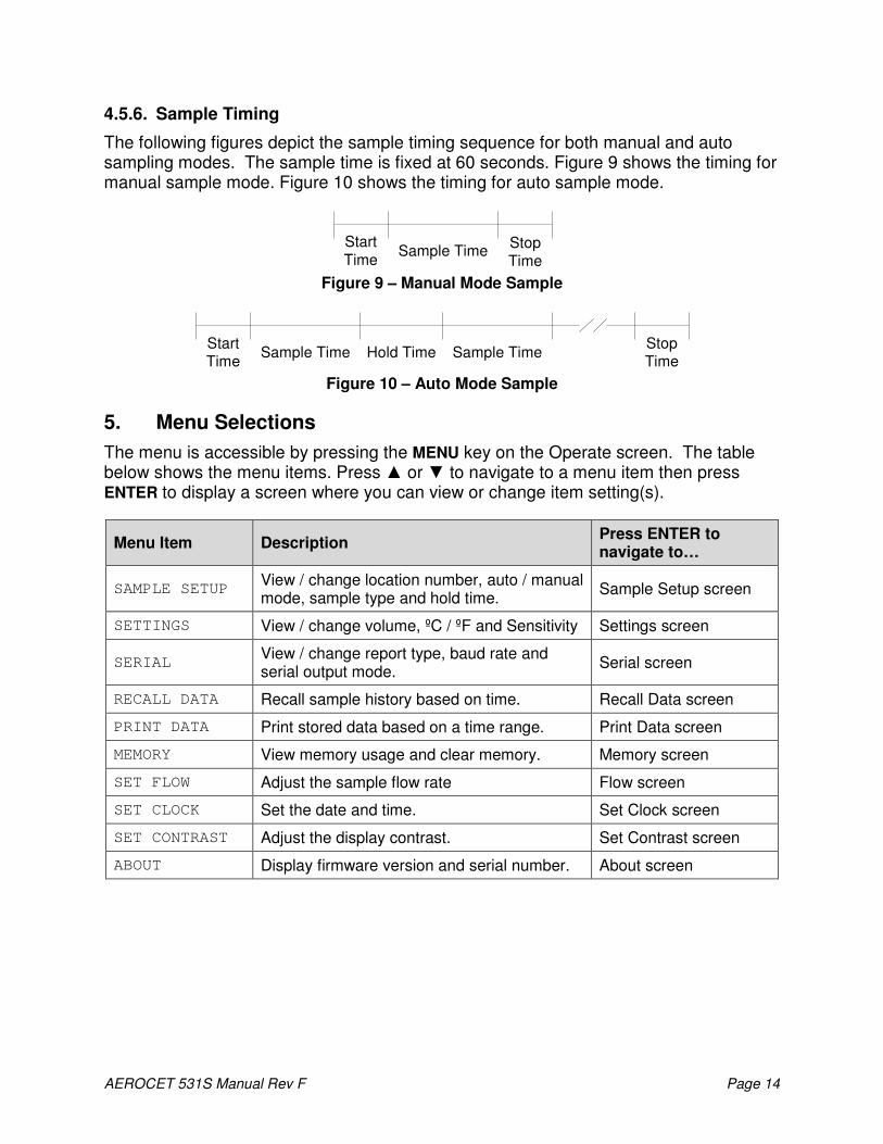
4.5.6. Sample Timing
The following figures depict the sample timing sequence for both manual and auto sampling modes. The sample time is fixed at 60 seconds. Figure 9 shows the timing for manual sample mode. Figure 10 shows the timing for auto sample mode.
Figure 9 – Manual Mode Sample
Figure 10 – Auto Mode Sample
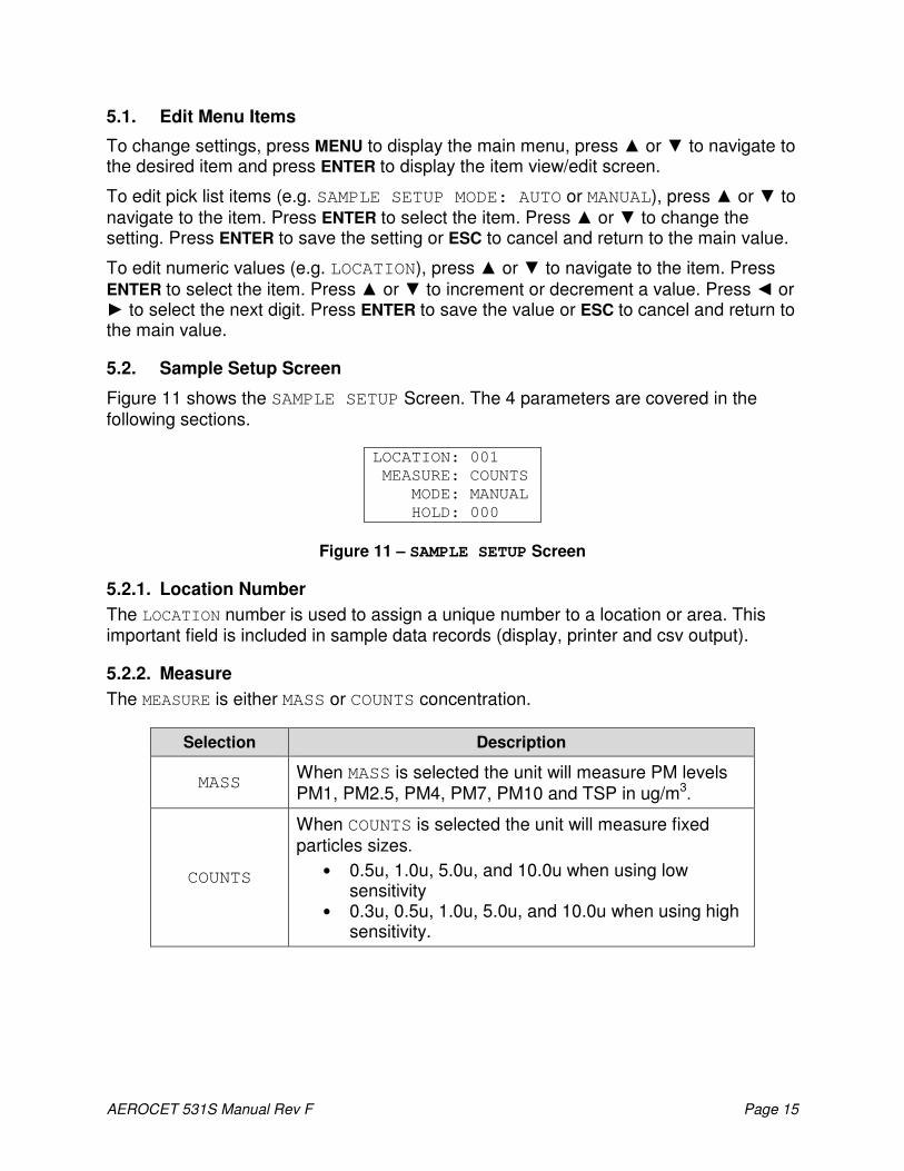
5. Menu Selections
The menu is accessible by pressing the MENU key on the Operate screen. The table below shows the menu items. Press ▲ or ▼ to navigate to a menu item then press ENTER to display a screen where you can view or change item setting(s).
Menu Item Description Press ENTER to navigate to…
SAMPLE SETUP View / change location number, auto / manual mode, sample type and hold time.
Sample Setup screen
SETTINGS View / change volume, ºC / ºF and Sensitivity Settings screen
SERIAL View / change report type, baud rate and serial output mode.
Serial screen
RECALL DATA Recall sample history based on time. Recall Data screen
PRINT DATA Print stored data based on a time range. Print Data screen
MEMORY View memory usage and clear memory. Memory screen
SET FLOW Adjust the sample flow rate Flow screen
SET CLOCK Set the date and time. Set Clock screen
SET CONTRAST Adjust the display contrast. Set Contrast screen
ABOUT Display firmware version and serial number. About screen
Start
TimeSample Time
Stop
Time
StartTime
Sample Time Hold Time Sample TimeStopTime
AEROCET 531S Manual Rev F Page 15
5.1. Edit Menu Items
To change settings, press MENU to display the main menu, press ▲ or ▼ to navigate to the desired item and press ENTER to display the item view/edit screen.
To edit pick list items (e.g. SAMPLE SETUP MODE: AUTO or MANUAL), press ▲ or ▼ to navigate to the item. Press ENTER to select the item. Press ▲ or ▼ to change the setting. Press ENTER to save the setting or ESC to cancel and return to the main value.
To edit numeric values (e.g. LOCATION), press ▲ or ▼ to navigate to the item. Press ENTER to select the item. Press ▲ or ▼ to increment or decrement a value. Press ◄ or ► to select the next digit. Press ENTER to save the value or ESC to cancel and return to the main value.
5.2. Sample Setup Screen
Figure 11 shows the SAMPLE SETUP Screen. The 4 parameters are covered in the following sections.
LOCATION: 001
MEASURE: COUNTS
MODE: MANUAL
HOLD: 000
Figure 11 – SAMPLE SETUP Screen
5.2.1. Location Number
The LOCATION number is used to assign a unique number to a location or area. This important field is included in sample data records (display, printer and csv output).
5.2.2. Measure
The MEASURE is either MASS or COUNTS concentration.
Selection Description
MASS When MASS is selected the unit will measure PM levels PM1, PM2.5, PM4, PM7, PM10 and TSP in ug/m3
.
COUNTS
When COUNTS is selected the unit will measure fixed particles sizes.
• 0.5u, 1.0u, 5.0u, and 10.0u when using low sensitivity
• 0.3u, 0.5u, 1.0u, 5.0u, and 10.0u when using high sensitivity.

AEROCET 531S Manual Rev F Page 16
5.2.3. Sample Mode
The sample MODE controls single sample or continuous sampling as illustrated below.
Selection Description
MANUAL The MANUAL setting configures the unit for a single sample.
AUTO The AUTO setting configures the unit for continuous sampling.
5.2.4. Hold Time
The HOLD time is the time between samples when sampling in AUTO mode (continuous).
The HOLD time is user settable from 0 – 999 seconds. The pump will remain on during
the hold period if the HOLD time is 60 seconds or less. The pump will stop after each
sample, and start a few seconds before the next sample, if the HOLD time is greater
than 60 seconds. HOLD times greater than 60 seconds will increase pump life.
5.3. Settings Screen
Figure 12 shows the SETTINGS screen.
VOLUME CF
TEMPERATURE C
SENSITIVITY LOW
Figure 12 – SETTINGS Screen
5.3.1. Volume
The AEROCET 531S supports total counts (TC), particles per liter (/L), particles per
cubic foot (CF), and particles per cubic meter (M3). Particle count information updates
while the unit is sampling. Concentration values (/L, CF, M3) are time dependent so these values may fluctuate early in the sample; however, after several seconds the measurement will stabilize.
5.3.2. Temperature
The AEROCET 531S displays ambient temperature (AT) in Celsius (C) or Fahrenheit (F).
5.3.3. Sensitivity
Select HIGH (0.3µm) or LOW (0.5µm) sensitivity. The default setting is HIGH. Use this setting for normal operation. Use the Low setting for high concentrations (for example, above 100µg) or when comparing measurements with older AEROCETS.

AEROCET 531S Manual Rev F Page 17
5.4. Serial Screen
Figure 12 shows the SERIAL screen.
REPORT: NONE
BAUD: 38400
SERIAL: RS-232
Figure 13 – SERIAL Screen
5.4.1. Report
The REPORT setting determines the behavior of the AEROCET 531S serial output and
report format. The settings are NONE, CSV or PRINTER. The following table lists the
REPORT settings and describes their meanings. See section 7 for report examples.
Selection Description
NONE No report is sent to the serial port at the end of the sample event. Reports initiated from the user interface or a serial command will be in a CSV style report.
CSV A CVS style report is sent to the serial port at the end of the sample event or when initiated from the user interface or a serial command.
PRINTER
A printer style report is sent to the serial port at the end of the sample event or when initiated from the user interface. Reports initiated by a serial command will be in a CSV style report.
5.4.2. Baud Rate
Use the BAUD rate selection to set the serial communications baud rate. AEROCET 531S communicates at baud rates from 300 – 38400.
5.4.3. Serial
The SERIAL setting controls the behavior of the AEROCET 531S serial output
hardware. The modes are RS-232 or RS-485. The following table lists the SERIAL settings and describes their meanings.
Serial Setting Description
RS-232 Set to RS-232 when communicating with RS-232/USB
hardware.
RS-485 Set to RS-485 when communicating with RS-485 hardware.

AEROCET 531S Manual Rev F Page 18
5.5. Recall Data Screen
Stored sample events can be viewed from the Operate screen but this requires navigating one record at a time to reach a desired record. The RECALL DATA screen provides a way to quickly navigate to a record based on time. Figure 14 shows the RECALL DATA screen.
RECALL DATA
01 JAN’00 00:00
Figure 14 – Recall Data Screen
To recall data, enter the desired date/time string and select the START/STOP button. The unit will recall the data from the date/time entered (if an exact match is found) or the next most recent data available. The screen shown when the data is recalled is the Operate screen. The unit will display “←←←←” on the upper right corner of the display to indicate history data.
5.6. Print Data Screen
Stored sample events can be printed through the serial port within a user selected range. To print selected data, select PRINT DATA from the menu. Figure 15 shows the
PRINT DATA screen. MEASURE: COUNTS
LOCATION: 001
01 JAN’00 00:00
18 AUG’06 13:23
Figure 15 – Print Data Screen
Edit the location and time range to select which sample events to print. The following table describes settings.
Setting Description
MEASURE Print MASS or COUNTS data type events.
LOCATION The location ID of the sample events to print. Setting location to 000 prints all locations. Settable from 0 – 999.
01 JAN’00 00:00 The date/time to begin printing sample events from.
18 AUG’06 13:23 The date/time to stop print samples at.

AEROCET 531S Manual Rev F Page 19
After the print settings have been selected, the PRINTING STATUS screen is displayed.
Figure 16 shows the PRINTING STATUS screen as it would look when finished.
PRINTING STATUS
SCANNING...15
PRINTING...10
FINISHED!
Figure 16 – Printing Status Screen
Pressing the ESC button cancels the data printing and loads the menu. The format of the print is dependent upon the SERIAL setting (Section 5.4).
5.7. Memory Screen
The AEROCET 531S memory is composed of a single file which contains the data from sample events. Every time a sample is completed, the AEROCET 531S stores that data into the memory. The AEROCET 531S memory is circular, meaning when the memory is full, the unit will start overwriting the oldest saved samples with new samples. AEROCET 531S provides the user the ability to view the memory usage as well as clear the memory.
5.7.1. View Available Memory
MEMORY screen is used to view available memory or to clear the memory. The MEMORY
screen is accessed by selecting MEMORY from the menu. Figure 17 shows the MEMORY screen.
FREE: 100%
SAMPLES: 6257
PRESS ENTER TO
CLEAR MEMORY!
Figure 17 – Memory Screen
FREE shows the percent of space available for data storage. When 0% is displayed,
memory is full and the oldest data will be overwritten by new data. SAMPLES shows the number of samples which can be store in memory before the memory is full. When 0% is displayed, memory is full and the oldest data will be overwritten by new data.
5.7.2. Clearing Memory
To clear memory, press the ENTER key while viewing the MEMORY screen. This will delete all the sample events in memory. A warning screen will be displayed to prevent accidental erasure.

AEROCET 531S Manual Rev F Page 20
5.8. Set Flow Screen
The AEROCET 531S has a factory calibrated flow rate of 0.1 CFM (2.83 LPM). Use the following procedure to adjust the flow rate when a periodic flow rate check (Section 8.3) indicates a flow rate error greater than +/- 5%.
SET FLOW
< > TO ADJUST
ENTER TO SAVE
███████
Figure 18 – Set Flow Screen
1. Connect a reference flow meter to the inlet fitting on the top of the unit (PN 9801).
2. Access the SET FLOW screen (Figure 18) by pressing MENU then select SET FLOW.
The pump will start automatically when you enter the SET FLOW screen and stop when you leave the screen.
3. Press ◄ or ► to obtain a reading of 0.1 CFM (2.83 LPM) +/- 5% on the reference flow meter.
4. Press ENTER to save the setting or ESC to cancel the change.
5.9. Set Clock Screen
To set the date and time select SET CLOCK from the menu. Figure 19 shows the SET
CLOCK screen and the following table describes the date / time formats.
SET CLOCK
DATE: 18 AUG’06
TIME: 11:25:36
Figure 19 – Set Clock Screen
Date / Time Formats
DATE dd MMM’yy dd – day, MMM’ – month, yy – year
TIME HH:mm:ss HH – hours, mm – minutes, ss – seconds

AEROCET 531S Manual Rev F Page 21
5.10. Set Contrast Screen
Press ◄ or ► to improve display quality. Press ENTER to save the setting or ESC to cancel the change. Figure 20 shows the SET CONTRAST screen.
SET CONTRAST
< > TO ADJUST
ENTER TO SAVE
███████
Figure 20 – Set Contrast Screen
5.11. About Screen
Figure 21 shows the ABOUT screen. The ABOUT screen shows the firmware version and programmable logic versions on the second line. The third line shows the manufacturer’s serial number. Press ▲ or ▼ to toggle between the two version numbers.
AEROCET-531S
99999-1 R9.9.9
N12345
WWW.METONE.COM
Figure 21 – About Screen
6. Charging the Battery
Caution: The provided battery charger is designed to work safely with this device. Do not attempt to connect any other charger or adapter to this device. Doing so may result in equipment damage.
To charge the battery, connect the battery charger to an AC power outlet and the DC barrel connector to the socket on the right side of the AEROCET 531S. The battery charger is universal and will work with power line voltages of 100 to 240 volts, 50 to 60 Hz. A discharged battery pack will take approximately 2.5 hours to fully charge.
When fully charged the battery inside the AEROCET 531S will power the unit for about 6 hours of continuous sampling. Under normal operation, the battery will power the unit for about 24 hours. For continuous operation, operate the unit with the battery charger attached. Charge the battery before storing the AEROCET 531S. Storing a discharged battery will degrade its performance.

AEROCET 531S Manual Rev F Page 22
7. Serial Communications
AEROCET 531S provides serial communications via the USB and DB9 connectors located on the right hand side of the unit. The following sections discuss the various serial communications available with AEROCET 531S.
ATTENTION: The included USB drivers must be installed before connecting the AEROCET 531S USB port to your computer. If the supplied drivers are not installed first, Windows may install generic drivers that are not compatible with this product. To install USB drivers: Insert the Comet CD. The install program should run automatically and display the screen below. If an AutoPlay pop-up window appears, select “Run AutoRun.exe”. Finally, select “USB Drivers” to start the install process. Users using a 32 bit system will want to run the USB 32bit drivers. Users using a 64 bit system will want to run the USB 64 bit drivers.
WARNING: The optional RS-232 serial cable (PN 3228) is specially wired to function with the AEROCET 531S. The use of any other cable can cause damage!

AEROCET 531S Manual Rev F Page 23
7.1. Serial Interface
The serial interface to the AEROCET 531S is a standard 9 pin (DB-9) connector. It is located on the right hand side of the instrument as shown below. Communication with the AEROCET 531S requires a custom serial cable (PN 3228). Standard serial cables will not work and may cause damage to the instrument if connected. Serial Cable PN 3228 is only for RS-232 communication. Below is a description of the DB-9 connector:
Pin Function Communication Type 1 Not Used 2 TX RS-232 3 RX RS-232 4 Not Used 5 Not Used RS-232 & RS-484 6 Not Used DAC 7 Analog Out 2 DAC 8 A+ RS-484 9 B- RS-484
1 2 3 4 5
6 7 8 9
AEROCET 531S Manual Rev F Page 24
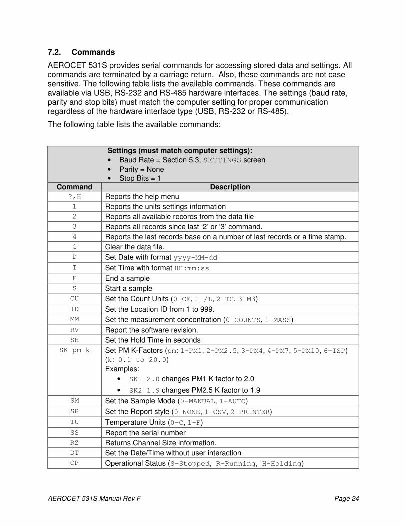
7.2. Commands
AEROCET 531S provides serial commands for accessing stored data and settings. All commands are terminated by a carriage return. Also, these commands are not case sensitive. The following table lists the available commands. These commands are available via USB, RS-232 and RS-485 hardware interfaces. The settings (baud rate, parity and stop bits) must match the computer setting for proper communication regardless of the hardware interface type (USB, RS-232 or RS-485).
The following table lists the available commands:
Settings (must match computer settings):
• Baud Rate = Section 5.3, SETTINGS screen
• Parity = None
• Stop Bits = 1 Command Description
?,H Reports the help menu
1 Reports the units settings information
2 Reports all available records from the data file
3 Reports all records since last ‘2’ or ‘3’ command.
4 Reports the last records base on a number of last records or a time stamp.
C Clear the data file.
D Set Date with format yyyy-MM-dd
T Set Time with format HH:mm:ss
E End a sample
S Start a sample
CU Set the Count Units (0-CF, 1-/L, 2-TC, 3-M3)
ID Set the Location ID from 1 to 999.
MM Set the measurement concentration (0-COUNTS, 1-MASS)
RV Report the software revision.
SH Set the Hold Time in seconds
SK pm k Set PM K-Factors (pm: 1-PM1, 2-PM2.5, 3-PM4, 4-PM7, 5-PM10, 6-TSP)
(k: 0.1 to 20.0)
Examples:
• SK1 2.0 changes PM1 K factor to 2.0
• SK2 1.9 changes PM2.5 K factor to 1.9
SM Set the Sample Mode (0-MANUAL, 1-AUTO)
SR Set the Report style (0-NONE, 1-CSV, 2-PRINTER)
TU Temperature Units (0-C, 1-F)
SS Report the serial number
RZ Returns Channel Size information.
DT Set the Date/Time without user interaction
OP Operational Status (S-Stopped, R-Running, H-Holding)
AEROCET 531S Manual Rev F Page 25
7.3. Real Time Output
The real time output occurs when the unit finishes a sample. The output format is either off (NONE), a comma separated value (CSV) or a printer (PRINTER) depending on the
REPORT style settings (see section 5.4.1)

AEROCET 531S Manual Rev F Page 26
7.4. Comma Separated Value (CSV)
The CSV report will be generated when the REPORT setting is set to CSV. The CSV format for MASS and COUNTS is
determined by the MEASURE setting. Both formats are fixed field length.
7.4.1. Counts Format
Count Data Report
2013-01-17 16:56:26
Serial Number, N12345
Time,0.3(M3),0.5(M3),1.0(M3),5.0(M3),10 (M3),AT(C),RH(%),Location,Seconds,Status
2013-01-17 15:49:06,04620275,03560226,00399152,00013069,00006358,+020,027,001,060,000
CSV Fields
Field Parameter Example Value Notes
1 Date and Time 2013-01-17 15:49:06
2 Channel 1 Size 0.3 (TC, /L, CF, M3) 04620275 Note 2
3 Channel 2 Size 0.5 (TC, /L, CF, M3) 00557753 Note 2
4 Channel 3 Size 1.0 (TC, /L, CF, M3) 00074178 Note 2
5 Channel 4 Size 5.0 (TC, /L, CF, M3) 00007417 Note 2
6 Channel 5 Size 10 (TC, /L, CF, M3) 00005298 Note 2
7 AT (C, F) +020 Note 2 & 3
8 RH (%) 027 Note 3
9 Location 001
10 Seconds 060 Note 4
11 Status 000 Note 5
Status Bits
Bit Value Condition
0 OK (no alarms or errors)
0 1 Not used
1 2 Not used
2 4 Not used
3 8 Not used
4 16 Low battery
5 32 Sensor error
Notes (for table above)
1. CSV header included for multiple record transfers like All Data (2) or New Data (3).
2. Units determined by product setting. 0.3 will be null (,,) if set to low sensitivity.
3. Temperature and RH will be null (,,) if Temp/RH probe is not attached
4. The sample time is fixed at 60 seconds. 5. Status bits combinations are possible. See the Status Bits table.

AEROCET 531S Manual Rev F Page 27
7.4.2. Mass Format
Mass Data Report
2013-01-22 11:59:52
Serial Number, N12345
Time,PM1(ug/m3),PM2.5(ug/m3),PM4(ug/m3),PM7(ug/m3),PM10(ug/m3),TSP(ug/m3),AT(C),RH(%),Location,Seconds,Status
2013-01-22 11:23:27,001.1,003.8,005.2,005.9,006.2,008.2,+020,026,001,060,000
CSV Fields
Field Parameter Example Value Notes
1 Date and Time 2013-01-22 11:23:27
2 PM1 (ug/m3) 001.1
3 PM2.5 (ug/m3) 003.8
4 PM4 (ug/m3) 005.2
5 PM7 (ug/m3) 005.9
5 PM10 (ug/m3) 006.2
6 TSP (ug/m3) 008.2
7 AT (C, F) +021 Note 2 & 3
8 RH (%) 40 Note 3
9 Location 001
10 Seconds 60 Note 4
11 Status 000 Note 5
Status Bits
Bit Value Condition
0 OK (no alarms or errors)
0 1 Not used
1 2 Not used 2 4 Not used
3 8 Not used
4 16 Low battery
5 32 Sensor error
Notes (for table above)
1. CSV header included for multiple record transfers like All Data (2) or New Data (3).
2. Units determined by product setting. 3. Temperature and RH will be null (,,) if Temp/RH probe is not
attached 4. The sample time is fixed at 60 seconds. 5. Status bits combinations are possible. See the Status Bits table.
For example, 48 (00110000B) = Low battery and Sensor error.

AEROCET 531S Manual Rev F Page 28
7.5. Printer Format
The printer report will be generated when the REPORT setting is set to PRINTER. The
printer format for MASS and COUNTS is based on the sample MEASURE setting. AT and RH will be displayed when the AT/RH probe is attached.
7.5.1. Counts Format
2013-01-22 11:40:51
Location 001
0.3u 4,620,275 M3
0.5u 3,560,226 M3
1.0u 888,731 M3
5.0u 15,542 M3
10 u 7,417 M3
AT 20 C
RH 26 %
7.5.2. Mass Format
2013-01-22 11:40:51
Location 001
PM1 1.1 ug/m3
PM2.5 3.3 ug/m3
PM4 4.6 ug/m3
PM7 5.5 ug/m3
PM10 6.7 ug/m3
TSP 10.6 ug/m3
AT 20 C
RH 26 %
8. Maintenance
Due to the nature of the instrument, there are no customer serviceable components in the AEROCET 531S. The case of the AEROCET 531S should never be removed or opened for any reason. Opening or removing the case of the AEROCET 531S voids the warranty and may result in exposure to laser radiation, which can cause eye injury.
8.1. Service Schedule
Although there are no customer serviceable components in the AEROCET 531S, there are service items which ensure the proper operation of the instrument. Table 1 shows the service schedule for the AEROCET 531S.
Time Period Item Manual Section
Weekly Zero Count Test 8.2 Monthly Flow Rate Test 8.3 Yearly Annual Calibration 8.4
Table 1 Service Schedule

AEROCET 531S Manual Rev F Page 29
8.2. Zero Count Test
Air leaks or debris in the particle sensor can cause false counts which may result in significant count errors when sampling clean environments. Perform the following zero count test weekly to ensure proper operation:
1. Attach zero count filter to the inlet nozzle (PN G3111).
2. Configure the unit as follows: Sample Mode = MANUAL, Volume = Total Count (TC), Measure = COUNTS.
3. Start and complete a sample.
4. The smallest particle size should have a count <= 1.
5. Run this test multiple times to flush out particles in the air stream if the goal is not met.
8.3. Flow Rate Test
The flow rate test verifies the sample flow rate is within tolerance. The reference flow meter must be non-loading because the vacuum pump can be loaded down by external restrictions. Met One Instruments sells a suitable flow meter (PN 9801). The flow rate test follows:
1. Connect a ±3% reference flow meter to the sample inlet nozzle.
2. Configure the unit as follows: Mode = AUTO.
3. Start sampling.
4. The flow meter reading after ~3 minutes should be 0.1 CFM (2.831 LPM) ±5%.
5. Adjust the flow rate if the error is > ±5% (see section 5.8).
8.4. Annual Calibration
The AEROCET 531S should be sent back to Met One Instruments yearly for calibration and inspection. The annual calibration cannot be performed by the customer because this calibration requires specialized equipment and a skilled technician. Met One Instruments maintains a calibration facility for calibrating particle counters according to industry accepted methods such as ISO, JIS and NIST. The annual calibration also includes inspection and preventative maintenance to improve product reliability.
8.5. Flash Upgrade
AEROCET 531S is firmware upgradeable via the serial connection using a Met One Instruments flash burn program. Binary files and the flash program must be provided by Met One Instruments.
AEROCET 531S Manual Rev F Page 30
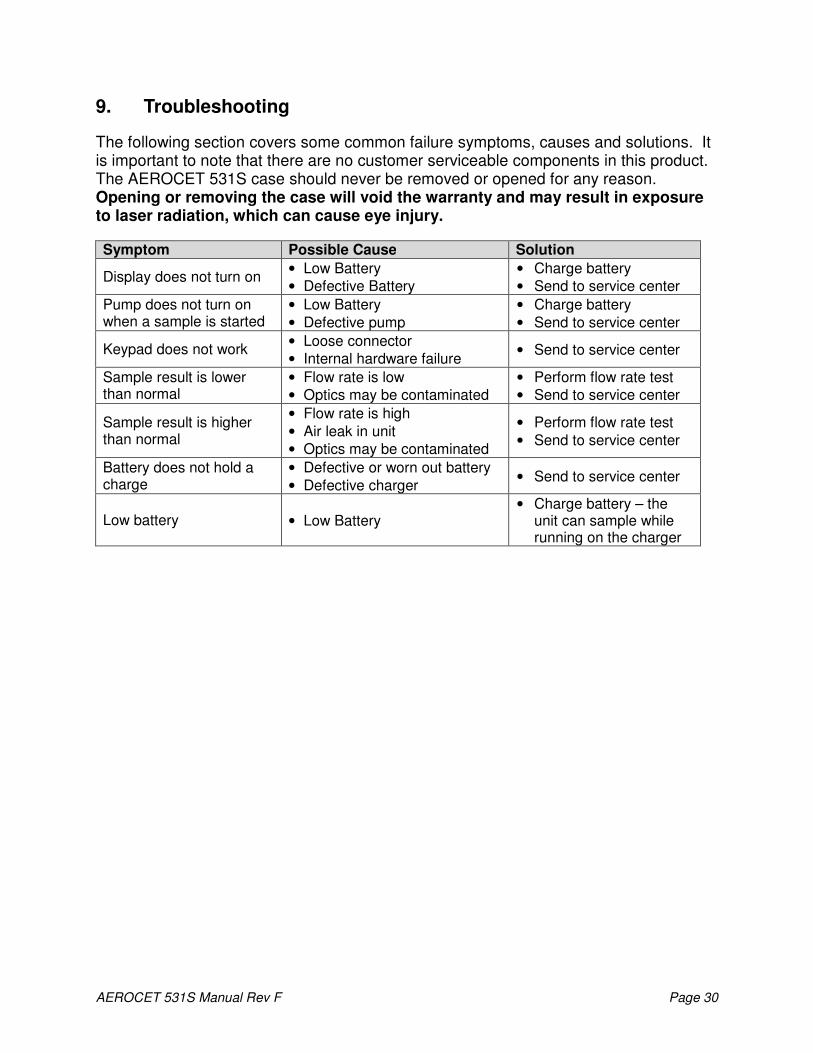
9. Troubleshooting
The following section covers some common failure symptoms, causes and solutions. It is important to note that there are no customer serviceable components in this product. The AEROCET 531S case should never be removed or opened for any reason. Opening or removing the case will void the warranty and may result in exposure to laser radiation, which can cause eye injury.
Symptom Possible Cause Solution
Display does not turn on • Low Battery
• Defective Battery
• Charge battery
• Send to service center
Pump does not turn on when a sample is started
• Low Battery
• Defective pump
• Charge battery
• Send to service center
Keypad does not work • Loose connector
• Internal hardware failure • Send to service center
Sample result is lower than normal
• Flow rate is low
• Optics may be contaminated
• Perform flow rate test
• Send to service center
Sample result is higher than normal
• Flow rate is high
• Air leak in unit
• Optics may be contaminated
• Perform flow rate test
• Send to service center
Battery does not hold a charge
• Defective or worn out battery
• Defective charger • Send to service center
Low battery • Low Battery • Charge battery – the
unit can sample while running on the charger

AEROCET 531S Manual Rev F Page 31
10. Specifications
Performance Particle Counter Sizes 0.3µm, 0.5µm, 1.0µm, 5.0µm, 10µm Mass Ranges PM1, PM2.5, PM4, PM7, PM10, TSP Concentration Range 0 – 3,000,000 particles per cubic foot (105,900 particles/L) Accuracy ± 10% to calibration aerosol Sensitivity High = 0.3 µm, Low = 0.5 µm Flow Rate 0.1 cfm (2.83 lpm) Sample Time 60 seconds Hold Time Adjustable: 0 to 999 seconds
Electrical
Light Source Laser Diode, 90mW, 780 nm Battery 7.4V Li-ion battery pack. Battery Life 6 hours continuous operation Battery Charge Time Fully changed in 2.5 hours AC Adapter/Charger Li-ion battery charger, 100 – 240 VAC, 50/60Hz, 0.2A Communications USB, RS-232 or RS-485
Interface
Display 16 character x 4 line LCD Keyboard 7 key membrane type
Physical
Height 6.25” (15.9 cm) Width 4.00” (10.2 cm) Depth 2.12” (5.4 cm) Weight 2.00 lbs (0.91 kg)
Environmental Operating Temperature 0º C to +50º C Storage Temperature -20º C to +60º C
Accessories
Supplied Operation Manual USB Cable Comet Software AC Adapter / Battery Charger Iso-kinetic Sample Probe Carrying Case Zero Particulate Filter (PN G3111)
Optional RH & Temperature Probe (PN G3120)
Flow Meter (PN 9801) Portable Printer (PN G3115) Custom Serial Cable (PN 3228)

AEROCET 531S Manual Rev F Page 32
11. Warranty / Service