Embed Size (px)
Citation preview

1
The macro element method in crashworthiness calculations - the state-of-the-art and the future
by
Wlodek Abramowicz
Abstract
Successful design of a crashworthy structure involves assessment of several
simulation models at various levels of simplification and accuracy. Typically a design
process starts from numerous analyses of semi-analytical and experimental models.
The more mature is the structure concept the more detailed simulation models are
needed. The macro element models take over the main load of simulation work at the
intermediate level of the design process when basic dimensions of the structure
undergoes frequent modifications.
This paper presents concise overview of the existing macro element technology
presented at the PUCA 2008 meeting in Tokyo. The discussed macro elements were
developed for car, train and ship industries and are implemented in the framework of
novel finite element formulation that is capable of handling both standard finite
elements as well as a variety of macro and user defined elements. Number of
examples is presented to illustrate potential of the new approach and indicate
directions of further research.
Introduction
The macro element method is derived from the kinematic method of plasticity and
energy method of classic elasticity. The leading idea of this method is to assume the
kinematics of deformed continua rather then calculate it from classic equations of
equilibrium. The macro element method is especially successful in the field of large
deformations of thin sheets and thin walled elements made of variety of materials.
The typical deformation pattern of thin elements is apparent in many areas of human
activity.

2
Figure 1 Folding patterns of fabric on Michelangelo tempera Holy Family and folded roof of a car
Perhaps the most spectacular illustration of this fact is noticeable in paintings and
sculptures of Michelangelo. The painting (tempera) in Figure 1 shows typical
configuration of fabric’s folds and wrinkles formed under the gravity forces. This
pattern is compared with plastic folds and wrinkles typical for crashed metallic sheet –
in this case deformed roof of a small passenger car.
It took several centuries before this apparent feature of thin sheets was utilized in
practical engineering calculations. The first kinematic solution directly related to
large distortions of thin shells subjected to crash loading is due to Alexander [1] and
was published in 1960. The leading idea of Alexander’s approach is to assume a class
of shape functions close to the experimentally observed deformation pattern of a shell
(or segment of the shell). Alexander considered progressive folding of cylindrical
shells now widely known as concertina pattern, Figure 2. The solution to the problem
was obtained by postulating inextensibility of the shell in the axial direction and
global minimum condition with respect to the length of the plastic folding wave,
denoted as 2H in Figure 2. The novel approach involved only few lines of elementary
calculations and rendered simple expressions for the length of the plastic folding wave
and energy absorption capacity of the shell.
Figure 2 Concertina folding of cylindrical tube and corresponding kinematic computational model due
to Alexander, [1]
Significant advances in the kinematic method of plasticity were made in early eighties
of the last century. At that time number of papers addressed most of the unresolved
issues present in early solutions. The following short description of milestones of the

3
emerging macro element methodology focuses on important practical results but does
not pretend to give a full review of the relevant literature.
The first key modification to early kinematic solution addressed the problem of
underestimated level of energy absorption. The theoretical solution for effective
crushing distance due to Abramowicz [2] allowed for the estimate of the height of
completely squeezed plastic lobe in axially compressed prismatic elements. The
effective crushing distance concept was then extensively validated experimentally by
Abramowicz and Jones [3], [4]. The next important contribution was the introduction
of the energy equivalent stress measure [5], [6] that allowed for reliable estimate of a
representative stress level in crushed shells.
Works due to Kecman [7] [8] published in late 70 and early 90 of the last century
showed a practical way of deriving semi-empirical solutions to the bending collapse
of rectangular and square sections. Kecman’s solutions required number of empirical
parameters to describe bending crushing characteristic but at the same time showed a
way of seamless connections of classic elastic solutions (up to the point of peak
bending moment) with kinematic results for deep collapse response.
Development of more general approach to the crushing of thin walled structures was
made possible by works of Wierzbicki, Jones and Abramowicz. The important
contribution of these authors was to isolate a typical buckling or folding pattern in
folded structural elements and describe its mechanical response. At that time the
general folding mechanism was referenced as Basic Folding Mechanism (BFM) and is
now considered to be a first prototype of the Super Folding Element [6] [9] [10] [11].
Further advances in the method should be attributed to works done at MIT in middle
eighties of the last century and summarized in eight Volumes of the Manual of
Crashworthiness Engineering, [5]. The manuals summarized the formulation of the
method and documented number of analytical solutions to various crushing
mechanisms in thin shells. The latter research was a starting point for the development
of the Superfolding Element (SFE) concept that was subsequently implemented in
specialized programs for design and calculation of energy absorbing structures,
[12] Error! Reference source not found.]. Since early 90 of the last century the
CAE programs based on the macro element concept are used in routine daily
engineering practice in virtually all branches of transportation industry.
The paper summarizes the current formulation of the macro element method and
presents recent advances in the generalization of the method to complex 3D structures.
The Macro Element Method
The general methods of structural mechanics like beam and shell theories or finite
element method are formulated at the level of differential equations of equilibrium
and are applicable to a wide class of structures subjected to variety of boundary and
loading conditions and constitutive relations. In contrast to these methods the macro
element formulation is dedicated to narrow class of structural elements or even to a
single type of a structural element (or its representative part). Consequently, sharp
restrictions are imposed onto the type of an analyzed structure and type of boundary
and loading conditions.
All the major steps of a typical macro element formulation are illustrated in this
section on the example of Superbeam Element, an essential element of the CAE
computer programs discussed later in this paper. Readers interested in more detailed
discussion of the formulation of the method are referred to the base publication on this
subject, [6] [11].
4
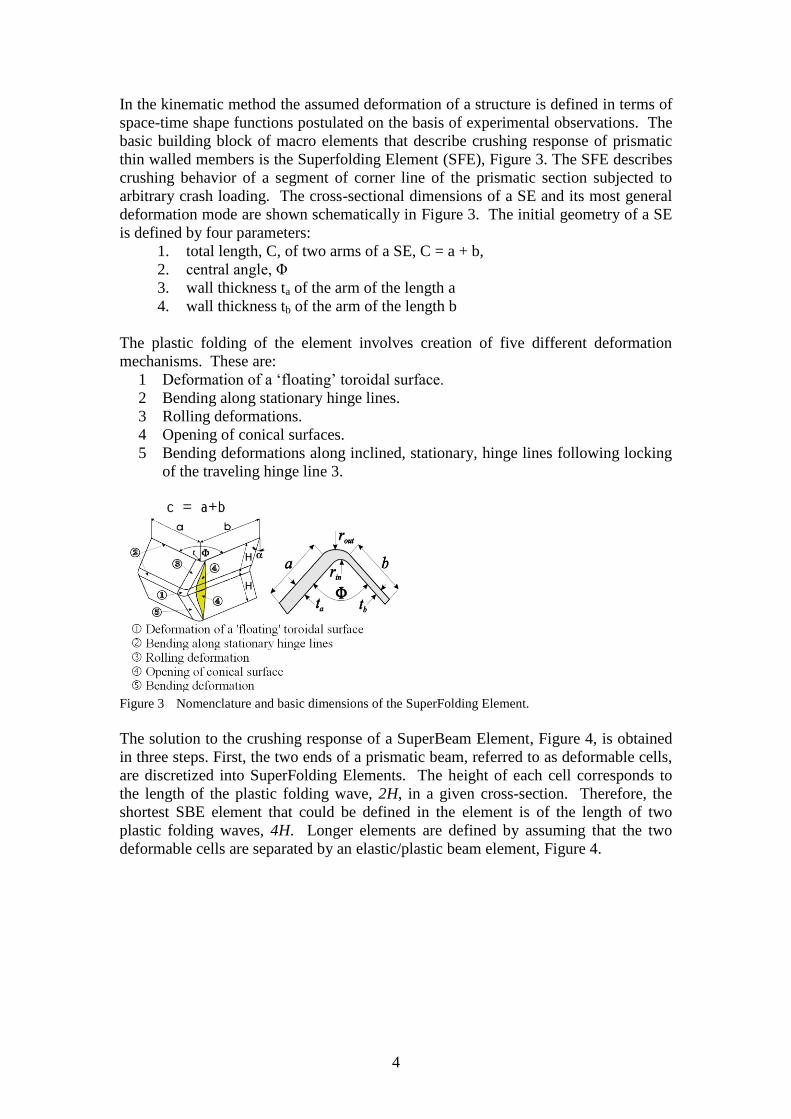
In the kinematic method the assumed deformation of a structure is defined in terms of
space-time shape functions postulated on the basis of experimental observations. The
basic building block of macro elements that describe crushing response of prismatic
thin walled members is the Superfolding Element (SFE), Figure 3. The SFE describes
crushing behavior of a segment of corner line of the prismatic section subjected to
arbitrary crash loading. The cross-sectional dimensions of a SE and its most general
deformation mode are shown schematically in Figure 3. The initial geometry of a SE
is defined by four parameters:
1. total length, C, of two arms of a SE, C = a + b,
2. central angle, Φ
3. wall thickness ta of the arm of the length a
4. wall thickness tb of the arm of the length b
The plastic folding of the element involves creation of five different deformation
mechanisms. These are:
1 Deformation of a ‘floating’ toroidal surface.
2 Bending along stationary hinge lines.
3 Rolling deformations.
4 Opening of conical surfaces.
5 Bending deformations along inclined, stationary, hinge lines following locking
of the traveling hinge line 3.
Figure 3 Nomenclature and basic dimensions of the SuperFolding Element.
The solution to the crushing response of a SuperBeam Element, Figure 4, is obtained
in three steps. First, the two ends of a prismatic beam, referred to as deformable cells,
are discretized into SuperFolding Elements. The height of each cell corresponds to
the length of the plastic folding wave, 2H, in a given cross-section. Therefore, the
shortest SBE element that could be defined in the element is of the length of two
plastic folding waves, 4H. Longer elements are defined by assuming that the two
deformable cells are separated by an elastic/plastic beam element, Figure 4.
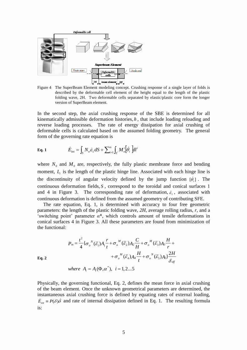
5
Figure 4 The SuperBeam Element modeling concept. Crushing response of a single layer of folds is
described by the deformable cell element of the height equal to the length of the plastic
folding wave, 2H. Two deformable cells separated by elastic/plastic core form the longer
version of SuperBeam element.
In the second step, the axial crushing response of the SBE is determined for all
kinematically admissible deformation histories, , that include loading reloading and
reverse loading processes. The rate of energy dissipation for axial crushing of
deformable cells is calculated based on the assumed folding geometry. The general
form of the governing rate equation is
Eq. 1 in
i Li
i
oS
o dlMdSNEi
11int
where 0N and 0M are, respectively, the fully plastic membrane force and bending
moment, iL is the length of the plastic hinge line. Associated with each hinge line is
the discontinuity of angular velocity defined by the jump function ][ i . The
continuous deformation fields, S , correspond to the toroidal and conical surfaces 1
and 4 in Figure 3. The corresponding rate of deformation,1 , associated with
continuous deformation is defined from the assumed geometry of contributing SFE.
The rate equation, Eq. 1, is determined with accuracy to four free geometric
parameters: the length of the plastic folding wave, 2H, average rolling radius, r, and a
‘switching point’ parameter α*, which controls amount of tensile deformations in
conical surfaces 4 in Figure 3. All these parameters are found from minimization of
the functional:
Eq. 2
5...2,1),,(
2})()(
)()()({4
*
5544
33221 1
2
iAAwhere
HA
t
HA
r
HA
H
CA
t
rA
tP
ii
eff
N
o
M
o
M
o
M
o
N
om
Physically, the governing functional, Eq. 2, defines the mean force in axial crushing
of the beam element. Once the unknown geometrical parameters are determined, the
instantaneous axial crushing force is defined by equating rates of external loading,
)(PEext and rate of internal dissipation defined in Eq. 1. The resulting formula
is:

6
Eq. 3 /),,( intEP
where is the rate of axial crushing and stands for deformation history.
Figure 5 Distribution of normal stresses in a square SBE subjected to axial compression and
bending, [15].
The last step of the solution procedure involves definition of bending and torsion
moments and interaction (hyper) surfaces for deformed end cells of the SBE. The
solution to the bending problem is based on the analysis of normal stresses
distribution at the boundary of deformable cells, [14] [15]. An example of the stress
distribution in the post-collapse range is illustrated in Figure 5 for a square beam bent
along major axis. The distribution shown in Figure 5 is constructed by considering
asymmetric crushing modes of contributing SFE. Once this is done the resulting
bending moment is defined by integrating the stress profile along the cross-section
line, L:
Eq. 4 L
dllM ),,,(),,(
Like in the case of axial crushing the bending moments are determined for all
kinematically admissible bending histories, . Following similar lines the torsion
crushing characteristics of the beam are found. When all crushing characteristics for
all contributing cross-section forces are determined the interaction hyper surface is
constructed. In general the interaction surface has the form, [12]:
Eq. 5 1
4
max
3
max
2
max
1
max
aa
z
z
a
y
y
a
T
T
M
M
M
M
P
P
where Pmax, Mymax, Mxmax and Tmax are, respectively, maximal values of axial force
bending moments and torque. The constants ia are functions of initial geometry,
material properties and deformation history and must be defined separately for each
cross-section. Schematic illustration of a 3D axial force-bending moment-torque
interaction surface is shown in Figure 6.
Figure 6 Schematic illustration of the evolution of the interaction surface in the deep collapse range
maxP
P
maxMy
My
maxT
T
1
1
1
A B
C

7
For each deformation step the position of interaction surface is uniquely defined by
the deformation history, . Actual values of cross-section forces on the other hand
are functions of current rates of deformation and are defined from the standard
normality rule.
Object Oriented Formulation
For many years application of the macro element method was limited to specific
structural elements, like concertina folding of circular tube, or simple structural
elements, like prismatic members subjected to elementary quasi static crushing
loading. The limitation comes from the relative complexity of a solution to the
dynamic response of macro elements and resulting difficulty in implementation of
macro elements in standard FE programs. The desired break-through solution
followed the widespread of Object-Oriented Programming (OOP), which inspired
development of object oriented formulation of the generalized finite element
method, [13]. This section provides for a short overview of the basic concepts of the
new Object Oriented Formulation of the generalized finite element method.
The OOP is an effective way of programming solutions to complex non-linear
problems. Central to the successful OOP is the unambiguous definition of all entities,
referred to as objects, contributing to a given model. In the case of FE-like approach,
intuitive definition of key objects is straightforward. ‘Nodes’ are the objects that
govern global equilibrium of the model while ‘Elements’ are the objects that impose
loading onto nodes as a result of motion of ‘Nodes’. The relation of these two key
objects to the governing Newton equation for a representative node is illustrated in
Figure 7.
Figure 7 Relationship between the equation of motion and Node-by-Node/Element-by-Element
technique.
The mass of the node M represents reduced inertia of all the elements connected to the
node while the vector of internal forces, intf represents a combined action of all the
loadings inserted onto the Node by connected elements. The external forces, either
‘given forces’ or body forces, are defined separately. It should be noted that once the
resultant internal force vector is defined (as either a constant force or a given function
of node’s kinematics) the time stepping solution to the above equation do not require
any knowledge on the type or number of elements connected to the node.
Consequently, the iteration step is performed on the set of nodes only. In the case of
explicit time stepping routine this operation is referred to as a node-by-node method.

8
Once the iteration step is completed, the internal state of all the contributing elements
is updated based on the current kinematics of the node set In FE nomenclature, this
procedure is referred to as a constitutive update. It is obvious that the constitutive
update is performed in the element-by-element manner. The above general description
of the simulation paradigm does not address particulars of the communication
between two key types of objects or particulars of the time stepping routines. Two
additional objects responsible for these tasks: the ‘Interface’ and ‘Iterator’ objects are
defined later in this section.
Node objects
When both forces and moments act on a node, the node equilibrium is governed by
the Newton-Euler equations of motion
Eq. 6 Frm
Eq. 7 JMJ
where F and M are the forces and moments exerted on the node, m is the node mass,
is the angular velocity, J is the inertia tensor, and r is the nodal acceleration in the
global coordinate system. Note that the rotary motion in Eq. 7 is defined in the local
coordinate system. When updating node orientation in space, angular velocity , is
transformed to the global coordinates and the instantaneous increment in angular
position is calculated from Eq. 8:
Eq. 8 t
The updated orientation of the node is defined by three unit vectors of the co-
rotational coordinate system coupled with each node, Eq. 9.
Eq. 9
nnn
nnnnnn
nnnnnn
jik
jaajajj
iaaiaii
)]cos(1)][([2)sin()(
)]cos(1)][([2)sin()(
111
111
Interface objects
The functionality of the interface object is explained in Figure 8 and Figure 9. The
cross-section loading in beams is defined at the centroid by summing forces and
moments parallel and perpendicular to the cross-section plane (bending and torsion
moments, axial and shear forces). The object capable of handling this functionality is
referred to as ‘Interface’.
Figure 8 Two beam elements connected at a Node.

9
Orientation of the interface is defined by the 3D coordinate system }{ i co-rotational
with the interface plane. The origin of the coordinate system, referred to as a node of
the beam element, marks the point of application of cross-section forces. When two
beams meet together at the Node object, marked as J in Figure 8 and defined by its
own co-rotational coordinate system }{ ii , the beam nodes, marked as I in Figure 9, do
not necessarily coincide with each other. The cross-section planes of both elements
have, in general, different orientation in space, and are located at certain distance
apart. However, following the basic assumption of the beam theory they are ‘rigidly’
connected with the Node object. Therefore, the reduction of forces from interfaces to
the Node as well as retrieving of kinematic variables in the interface coordinate
system is done easily by simple vector transformations between two 3D coordinate
systems. This procedure is much simpler then standard method involving matrix
transformations.
Figure 9 The concept of the interface object.
The element concept
The general term ‘element object’ refers to any finite part of a solid or structure. It is
assumed that the response of an element is uniquely defined by the kinematics of
interfaces defined on that element.
Figure 10 The internal mechanics of a beam element is uniquely defined by the kinematics of two
interfaces.
For example, in the case of a beam element in Figure 10 the dynamic response of the
‘element’ is uniquely defined by the kinematics of two interfaces regardless of the
employed beam theory.
In the object oriented formulation elements are divided into two basic groups: Finite
Elements (FE) and Macro Elements (ME). The division is functional rather then
formal. The name Finite Element applies to all classic elements that are defined and
updated following standard FEM matrix paradigm. These elements can be
implemented directly as ‘encapsulated objects’ with only minor re-coding of standard
FE algorithm. All remaining elements are referred to as Macro Elements and can be
defined by any algorithm, expression, separate program and/or any rule that can be
cast into the form of a computer code.

10
The CAE software based on the macro element concept
The number of programs based on the Macro Element concept is rather small in
comparison to large offer of classic FE programs. The most renowned Macro
Element programs are closely related to the crashworthiness of cars (Crash Cad and
Visual Crash Studio) and tanker/ships crashworthiness (DAMAGE). This section
describes basic concepts implemented in the program Visual Crash Studio (VCS) - a
successor of Crash CAD. The VCS is probably the most advanced software for
design of energy absorbing sections and simulation of crushing response of arbitrary
space frames. The VCS is widely used in the automotive industry worldwide.
The Visual Crash Studio program
Design of energy absorbing structures is achieved in several steps, usually in a highly
iterative design/calculation process. Objectives of each design step are achieved by
usage of dedicated computational tools typically different for each step. The selection
of an appropriate tool depends on the complexity of the problem and availability of
suitable software or other predictive techniques such as engineering formulas,
empirical data or handbook - type information. The major problem prohibiting
effective usage of various techniques in a single design/calculation environment is the
lack of compatibility between simulations tools. The difficulty of combining various
discretization/solution techniques into single software is not only a technical problem
of different input/output organization. The primary problem lies deep in the generic
formulation of the FE and semi-analytical or macro element methods. The calculation
algorithms of these methods are frequently inherently different. The first successful
combination of macro element and flexible FE-like simulation environment is
achieved in the program Visual Crash Studio (VCS), [12]. VCS effectively combines
complex macro element solutions at the level of individual elements with object
oriented implementation of the global equilibrium solvers. This section describes two
major areas of application of the VCS. These are design and calculation of thin
walled members for optimal crash performance and flexible crash simulation of
structural sub-assemblies and complete space frame structures. It should be noted that
early predecessor of VCS the CAE program Crash Cad was capable of calculation and
design at the cross-section level only. Now the enhanced functionality of this
program is included as one of several dedicated design modules of VCS.
Crashworthiness analysis at the level of individual members
The design of a structural member at the cross - sectional level is especially important
at the pre - design and early design stages when the proper shape and optimal
dimensions of a member are sought and the design concept undergoes frequent
modifications. The macro elopement approach is especially attractive at this level as
the calculation routines require as input only overall dimensions of the cross – section,
and tensile characteristic of the material while the calculation process takes only few
seconds on a standard PC. Consequently, designer can examine a wide range of
cross - sectional topologies and run several parametric studies within only few hours
of work. The simplicity of cross section modeling by means of macro elements is
illustrated in Figure 11 for a typical hat cross - section made of aluminium alloy.

11
Figure 11 Input data screen of VCS with a discretized cross - section of a hat member defined by major
overall dimensions of the cross section, position of spot-welds and material characteristic.
Design of cross sections for axial crush
Calculations at the cross - sectional level are the first essential step in all Superbeam
calculations. This section shows how basic calculations are used to predict crushing
response of a single prismatic member.
One of the most sensitive parts of the design at the level of a single prismatic section
is concerned with progressive folding during a head - on collision. Among all
possible deformation modes of prismatic sections the progressive folding absorbs
most of the impact energy. At the same time, this folding mode is the one most
difficult to obtain in a real - world design. Development of progressive folding
requires simultaneous completion of several conditions. These are:
The cross - section geometry must be properly designed in order that the local
deformation of a section in each plastic lobe can be accommodated without
internal contacts and penetrations. In addition, the deformation of each plastic
lobe must be compatible with the deformation of it's closest neighbour,
Spot welds (rivets or laser weld - line) must not interfere with the local plastic
deformation of a section,
The section must be properly “triggered” through the introduction of correctly
designed hoop dents which guarantee the development of a proper folding
mode and reduce the peak load to such a level that the potentially unstable
plastic deformations are induced only in the region of triggering dents
and finally
The boundary and loading conditions (stiffness of joints, loading direction) are
kept in the range that guarantees the predominantly axial loading of the section.
The first three conditions, pertinent to the level of a single member, must be met at the
design stage of a given member while the last condition must be checked at the level
of full crash simulation of a car. This task requires an interaction of component level
design routine with simulation of the crash response of complete model of the space
frame.
Typically cross section optimization is done iteratively in several optimization steps.
At each step the program provides the user with information on the design errors at
the level of single Superfolding element (that models crushing behavior of individual
corners of prismatic members) and at the level of the whole cross section. The cross
section analysis module lists necessary corrections to the cross - sectional geometry

12
up to the point when the section can collapse progressively without internal contacts
and/or penetrations. This stage of the design requires fine-tuning of central angles,
widths of side faces and appropriate geometry of spot welding. An example of initial,
bad design of a rocker panel and final, correct design are shown in Figure 12. It
transpires from Figure 12 that both cross-sections are quite similar and the decision on
the correctness of the design is impossible without a detailed analysis of the folding
mechanics.
Figure 12 Initial (bad) and final (correct) geometries of a rocker panel optimized for axial crash
through a proper selection of central angles and widths of side faces. Red bullets on the first
sketch mark flows in the crashworthy design – in this case improper central angles.
The final stage of cross-section design is concerned with appropriate triggering
mechanism. An example of triggering dents, designed on the basis of macro element
folding analysis, is shown in Figure 13 for hexagonal columns with flanges.
Introduction of triggering dents in members designed for axial crash is necessary in
order to promote a desired progressive folding pattern and reduce the peak force
below the level, which is likely to induce global, Euler - type buckling of a column.
A triggering of columns is especially important for complex cross - sections that
develop a large number of natural folding modes. Usually only few of these modes
are likely to converge to the desired progressive folding pattern while other modes
lead to a premature bending of a column.
Figure 13 Paper model shows triggering dents in hexagonal column with flanges designed on the basis
of VCS calculations.

13
The importance of proper triggering is further clarified on the example of laboratory
experiment on a simple cross - sectional geometry, [4]. The first photograph in Figure
14 shows a long square prismatic column made of mild steel. Such a column has a
cross - sectional geometry that guarantees proper folding without internal contacts and
does not contain spot welds that may destroy progressive folding pattern. A properly
triggered square column collapses progressively up to the point when the last plastic
fold is completed.
(a).
(b). Figure 14 Progressive collapse of a properly triggered long square column, top, and global bending or
irregular folding of untriggered columns, bottom.
For example, the 54x54x1.4 mm square column at the top of Figure 14 a was
squeezed over 700 mm and developed 32 symmetric plastic lobes with no sign of any
global bending (the completely squeezed column in this figure was initially one-half
of the size of the longer column and developed 16 lobes). The total energy absorbed
was 25 kJ, which is sufficient to bring to the rest a 1000 kg car traveling with an
initial velocity of 25 km/h. On the other hand much shorter, untriggered, columns in
Figure 14 b collapsed in bending or deteriorated from progressive folding despite of a
carefully controlled loading and boundary conditions at both ends of a column.
Higher order macro elements
The preceding sections discussed several macro elements that describe crushing
response of elementary structural elements. These elements are referred to as first
order macro elements. Successful usage of these elements in an actual design practice
encouraged development of even more complex elements that are capable of
modeling and optimization of complete sub-structures and structural assemblies.
These elements, frequently containing several first order macro elements, are referred
to as higher order macro elements. Currently operational higher order elements are
capable of modeling dynamic response of honeycomb barriers, tapered thin-walled
elements, semi-rigid bodies and thin walled joints, [12]. The latter structure is
discussed in the following paragraph in order to illustrate the growing potential of the
new family of macro elements.
The SuperJoint Element models the connection of several thin-walled beams in a
single structural member. A well known and practically important example of a joint

14
is the connection of rocker panel with B-pillar and floor cross member of an
automobile body. The macro element that models crushing behaviour of a joint is
referred to as SuperJoint Element (SJE) and is developed to address the problem of
optimal joint design and increase modeling potential of macro element models.
The SJE is defined as an assembly of several SuperBeam Elements referred to as legs
of a joint. The joint legs are interconnected by a “core” of a joint. The SuperJoint
Element offers several options of core modeling at various stages of the design of a
structure. The simplest model of a joint assumes infinite rigidity of the core. The rigid
core model offers realistic references point for the optimal joint design where core is
“stronger” then the legs and do not promote premature collapse of the joint.
Elementary examples of “weak” and “strong” joint response are illustrated in Figure
15, which shows that that correctly designed core is “stronger” then connected beams
and therefore do not deform under applied crash loadings.
In the case of perfectly rigid core all the beams meet at one node (with appropriate
offsets) and retain original beam response; i.e. crushing of one beam is not coupled
with the crushing response of remaining beams. In particular this modeling procedure
does not account for local denting and lateral crushing of joints, typical for “weak” -
badly designed core.
Figure 15 “Weak” and “strong” joint response under axial crashing of vertical beam.
The core of a SuperJoint is subjected to combination of axial loading, bending, torsion
and denting deformations. Pre-design of a joint is facilitated in SJE in two steps. In
the first step the connecting shells are designed in such a way that the strength of core
under beam-like combined loading (axial, bending and torsion) is higher then the
strength of contributing legs and consequently local collapse occurs in joint leg(s)
rather then in a core. In the second, “fine-tuning”, design step the shell-like denting
response of connecting shells and SBE(s) is analyzed in order to account for possible
denting deformations and suggest local stiffening of connecting shells and SBE.
The performance of SJE is illustrated on the example of elementary T joint with
square cross-section that is fixed in all 6 d.o.f. in horizontal legs and translational d.o.f.
of the vertical leg. Quasi-static skewed bending loading is applied to the vertical leg
so the leg is bent in a diagonal plane of the square cross section. The slanted
connecting shells were modified up to the point when collapse of the joint occurred in
the vertical leg rather then in the joint core.

15
0
2000
4000
6000
8000
10000
0 10 20 30 40
Time [msec]
Mo
men
t [N
m]
Figure 16 Quasi static bending crushing of elementary T joint. Solid line SJE prediction, broken line
FE results.
The results of macro element calculations are shown in Figure 16 together with FE
calculations that were run for final design of the joint in order to verify the prediction
of calculation/design macro element procedure.
Examples of application
The VCS is relatively new software that integrates complete macro element algorithm
with the FE-like simulation environment. Despite that several benchmarking tests
were already done at universities and automotive R&D departments in order to verify
accuracy of the software and its applicability to the design process. This section
summarizes just few representative examples of the application of the macro element
method in automotive industry.
The target components of the benchmarking study at Honda R&D, [17], are illustrated
in Figure 17.
Figure 17 Target components of body in white tested in this evaluation program, [16]
All macro element models were created semi-automatically by using the CAD–macro
element program interface. Simulations were run in parallel for both macro element
and FE models. The example of simulation results for rear frame assembly is shown
in Figure 18. The exceptionally good agreement of simulation with respect to both
crushing characteristics and deformation shape is evident from the graphs in this
figure.

16
0
20
40
60
80
0 20 40 60 80 100
Stroke [mm]
Fo
rce [
kN
]
Figure 18 Quasi static deformation of rear frame. Undeformed FE model and deformed macro element
model. VCS – red curve, FE black curve
The 56 km/h frontal crash of the Ford Taurus structure was studied by Lasek at
al, [18]. The macro element model consisted of 45 nodes and 56 macro elements and
required 30s CPU on a 2MHz Windows PC. The macro element simulation results
were then compared with standard FE simulation. Results of both simulations are
compared in Figure 20 and Figure 19. Global collision parameters: shortening-time
and c.g. velocity-time histories are compared in Figure 20. Figure 19 shows deformed
configurations of both models in 10 milliseconds intervals.
Figure 19 Velocity- time and shortening-time histories for macro element and FE models.

17
Figure 20 History of deformation in 10 milliseconds intervals. Upper rows – macro element model,
lower rows FE models, [18].
Conclusions
The macro element method, formulated in the 50 and 60 of the last century was used
extensively in the mechanics of elastic shells and plates. This method was then
generalized to describe crushing response of thin walled components. Rapid
development of FE codes significantly limit practical application of the macro
element method in nonlinear elastic analysis. At the same time the macro element
approach is extensively used in the crashworthiness community for fast analysis and
preliminary design of energy absorbing structures. Recent developments in macro
element methodology, described in last sections of this paper, confirm robustness and
accuracy of macro element models in crashworthiness simulations.
Further development of the method will most probably be guided by industry needs.
The effective design/calculations environments are now intensively sought by many
automotive manufacturers and most probably this sector of industry would direct
further development of macro element method toward seamless integration with other
numerical tools. The CAE program VCS is just a first step in this direction and its
further development to include classic FE elements is highly feasible.

18
References [1] Alexander, J. M. An approximate analysis of the collapse of thin cylindrical shells under axial
loading, Q. J. Mech. Appl. Math., 13, 1, 10-15 (1960).
[2] Abramowicz, W., The Effective crushing distance in axially compressed thin-walled metal
columns., Int. J. Impact Engng., 1, 3, 309-317, (1983).
[3] Abramowicz, W., Jones, N., Dynamic progressive buckling of circular and square tubes., Int. J.
Impact Engng., 4, 4, 243-270, (1986).
[4] Abramowicz, W., Jones, N., Transition from Uniform Bending to Progressive Buckling of Tubes
Loaded Statically and Dynamically, Int. J. Impact Engng - Special issue in honour of Professor W.
Johnson's 75th birthday, Int. J. Impact Engng., 19, 5-6, 415-437, 1997.
[5] The Manual of Crashworthiness Engineering, ( Wierzbicki T. Editor.) Center of Transportation
Studies, Massachusetts Institute of Technology, (1988-1991).
[6] Abramowicz, W., Macro element method in crashworthiness of Vehicles in Crashworthiness –
energy management and occupant protection (Ambrosio J. Editor), SpringerWienNewYork, 2001.
[7] Kecman, D., Bending collapse of rectangular and square section tubes in relation to the bus roll
over problem, PhD Thesis, Canfield Institute of Technology, UK, (1979).
[8] Kecman, D., Program West for optimization of rectangular and square section tubes from the safety
point of view, Fourth Int. Conf. on Vehicle structural mechanics, (SAE paper 811312), (1981)
[9] Wierzbicki, T., Abramowicz, W., On the crushing mechanics of thin-walled structures., J. App.
Mech., 50, 727-734, (1983)
[10] Abramowicz, W., Wierzbicki, T., Axial crushing of multicorner sheet metal columns., J. App.
Mech., 56, 1, 113-120, (1989).
[11] Abramowicz, W., Extremal Paths in Progressive Plasticity, Int. J. Impact Engng, 18, 7-8, 753-764,
(1996).
[12] Visual Crash Studio (VCS) User's Manual, Impact Design, Europe, 2006.
[13] Abramowicz, W., An alternative formulation of the FE method for arbitrary discrete/continuous
models, Int. J. Impact Engng., 30, 8-9, 1081-1098, (2004).
[14] Wierzbicki, T., Recke, L., Abramowicz, W., and Gholami, T., Stress Profiles in Thin-Walled
Prismatic Columns Subjected to Crush Loading. Part I. Compression., Computers & Structures, 51,
6, 611-623, (1994)
[15] Wierzbicki, T., Recke, L., Abramowicz, W., and Gholami, T., Stress Profiles in Thin-Walled
Prismatic Columns Subjected to Crush Loading. Part II. Bending., Computers & Structures, 51, 6,
625-641, (1994).
[16] Takada, K., and Abramowicz, W., Fast Crash Analysis of 3D Beam Structures Based on Object
Oriented formulation, SAE 04B-119, (2003)
[17] Takada, K., Abramowicz, W., K., Hosokawa, T., Tatsuda, Eiji., Tomozawa, K., Egawa, Y., Mae,
Development of macro element model of large deformation automotive space frame, JSAE papers
(2006) – in print (in Japanese).
[18] Lasek, L., Bohm, D., Schindler, V., Vehicle layout tools for the early stage of the development
process, Proceedings of the VPD Conference. 24-26 October 2005. Munich, Germany.


![Hunter, P - Finite Element Method & Boundary Element Method [Course Notes 2003]](https://img.dokumen.tips/doc/110x75/55cf9942550346d0339c749a/hunter-p-finite-element-method-boundary-element-method-course-notes-2003.jpg)


![Hunter, P - Finite Element Method & Boundary Element Method [Course Notes 2001]](https://img.dokumen.tips/doc/110x75/552d570e4a7959c6598b4696/hunter-p-finite-element-method-boundary-element-method-course-notes-2001.jpg)

