Embed Size (px)
Citation preview
Advanced Technologies for the Controlof Sulfur Dioxide Emissions from Coal-Fired Boilers
TOPICAL REPORT NUMBER 12 JUNE 1999

TOPICAL REPORT NUMBER 12
A report on three projects conducted under separatecooperative agreements between:
The U.S. Department of Energy and • Pure Air • Southern Company Services • New York State Electric & Gas Corporation
JUNE 1999
Advanced Technologiesfor the Control ofSulfur Dioxide Emissionsfrom Coal-Fired Boilers

Cover image: Plant Views ofBailly, Yates, and Milliken Stations
Executive Summary........................................................................................... 1
Background........................................................................................................ 2
Emission Standards ........................................................................................... 4
Clean Coal Technology Wet FGD Demonstration Projects .............................. 4
Advanced Flue Gas Desulfurization (AFGD) Demonstration Project ........... 5
Demonstration of Innovative Applications of Technology for the CT-121 FGD Process ..................................................................... 11
Milliken Clean Coal Technology Demonstration Project ............................ 19
Conclusions ..................................................................................................... 23
Bibliography .................................................................................................... 24
Contacts ........................................................................................................... 26
List of Acronyms and Abbreviations ............................................................. 27
Advanced Technologiesfor the Control ofSulfur Dioxide Emissionsfrom Coal-Fired Boilers
Executive Summary
The Clean Coal Technology (CCT)Program is a government and industry
cofunded effort to demonstrate a new
generation of innovative coal utilizationprocesses in a series of “showcase” facili-
ties built across the country. These projects
are carried out on a scale sufficiently largeto demonstrate commercial worthiness and
to generate data for design, construction,
operation, and technical/economic evalua-tion of full-scale commercial applications.
The goal of the CCT Program is to fur-
nish the U.S. energy marketplace with a num-ber of advanced, more efficient coal-based
technologies meeting strict environmental
standards. These technologies will mitigatethe economic and environmental impedi-
ments that limit the full utilization of coal
as a continuing viable energy resource.To achieve this goal, beginning in 1985,
a multiphased effort consisting of five
separate solicitations was administeredby the U.S. Department of Energy’s
(DOE) Federal Energy Technology Center
(FETC). Projects selected through thesesolicitations have demonstrated technology
options with the potential to meet the needs
of energy markets while satisfying relevantenvironmental requirements.
Part of this program is the demonstra-
tion of technologies, referred to as flue gasdesulfurization (FGD) processes, designed
to reduce sulfur dioxide (SO2) emissions
from coal-fired power plants. Emissionsof SO2, a precursor of acid rain, are regu-
lated under the provisions of the 1990
Clean Air Act Amendments (CAAA).This Topical Report discusses three com-
pleted CCT projects that successfully dem-
onstrated SO2 emissions reductions viainnovative FGD processes. The goal of all
three projects was to achieve greater than
90% SO2 removal. This goal was achieved,
with SO2 removals as high as 98% being
demonstrated. High particulate removalefficiencies were also achieved. In addition,
these processes demonstrated the capabil-
ity of producing wallboard-quality gypsum,a marketable by-product, thereby eliminat-
ing the need for FGD sludge disposal, a ma-
jor problem for many conventional FGDprocesses.
• Advanced Flue Gas Desulfurization
(AFGD) was demonstrated at NorthernIndiana Public Service Company’s Bailly
Station, near Gary, Indiana. The project
was conducted by Pure Air on the Lake,L.P., a company formed by the process
developer, Pure Air, which is a partnership
between Air Products and Chemicals, Inc.and Mitsubishi Heavy Industries America,
Inc. The scrubber was of unique design,
incorporating cocurrent flow of gas andliquid. Coal sulfur content varied between
2.3% and 4.5%, typical of high-sulfur
bituminous coals. A total of 210,000 tonsof high-quality gypsum was produced
during the demonstration and sold to a
wallboard manufacturer.• Innovative Applications for the
CT-121 FGD Process was demonstrated
at Georgia Power’s Plant Yates, Newnan,Georgia, using a novel scrubber called
a jet bubbling reactor. This single process
vessel replaces the usual spray tower/reaction tank/thickener arrangement.
The fiberglass-reinforced plastic used
as the construction material proved highlycorrosion resistant. Coal sulfur content
ranged from 1.2% to 4.3%. In addition
to SO2 removal, the system also washighly efficient in removing hazardous
air pollutants from the flue gas.
• Milliken Clean Coal Technology
was demonstrated at New York State
Electric & Gas Corporation’s (NYSEG)
Milliken Station at Lansing, New York.On May 14, 1999, NGE Generation, an
affiliate of NYSEG, completed the sale
of its coal-fired power plants in New York
State, including Milliken Station, to
The AES Corporation. The FGD tech-nology demonstrated at Milliken uses
the Saarberg-Holter-Umwelttechnik
(S-H-U) process, which incorporatesa unique cocurrent/countercurrent flow
path plus formic acid for enhanced absorp-
tion of SO2. The Stebbins tile-lined, rein-forced concrete absorber exhibited superior
corrosion and abrasion resistance. FGD
availability during the test period was99.9%. Coal sulfur content averaged 3.2%.
The technologies described in this reportare capable of high levels of SO2 removal
and have proven to be very reliable. Through
the use of efficient, compact absorber equip-ment and the elimination of spare reactors,
these technologies offer costs significantly
lower than those of previous wet FGDprocesses. As a result, higher standards for
FGD performance and economics have
been set. With increasingly stringent airquality regulations, these innovative FGD
technologies should find numerous com-
mercial applications.Through these CCT demonstrations
and related projects, significant experience
has been gained by U.S. suppliers of FGDsystems and system components. This exper-
tise includes operating techniques, equip-
ment designs, and selection of materialsof construction. These CCT projects have
demonstrated advanced features, several
of which have been adopted by commer-cial FGD suppliers, thereby accruing sub-
stantial cost savings to U.S. electric utilities
and their customers. This has led to cost-effective answers to design challenges for
equipment such as reaction vessels, pumps,
and a wide variety of other items.
1
Advanced Technologiesfor the Control ofSulfur Dioxide Emissionsfrom Coal-Fired Boilers
Background
HistoryThe Clean Coal Technology (CCT)
Program, sponsored by the U.S. Depart-
ment of Energy (DOE), is a governmentand industry cofunded technology develop-
ment effort conducted since 1985 to demon-
strate a new generation of innovativecoal-utilization processes.
The CCT Program involves a series
of “showcase” projects, conducted on ascale sufficiently large to demonstrate
commercial worthiness and generate data
for design, construction, operation, andeconomic/technical evaluation of full-scale
commercial applications. The goal of the
CCT Program is to furnish the U.S. energymarketplace with advanced, more efficient
coal-based technologies meeting strict en-
vironmental standards. These technologieswill mitigate some of the economic and en-
vironmental impediments that inhibit the
full utilization of coal as an energy source.
Environmental RegulationsConcurrent with the development of the
CCT Program by DOE, the U.S. Environ-
mental Protection Agency (EPA) has pro-
mulgated regulations under the 1990 CleanAir Act Amendments (CAAA) controlling
emissions from a variety of stationary
sources, including coal-burning boilers.The CCT Program has opened a channel
to policy-making bodies by providing data
from cutting-edge technologies to aid informulating regulatory decisions. For ex-
ample, results from several CCT projects
have been provided to EPA to help estab-lish achievable nitrogen oxides (NOx)
emissions targets for coal-fired boilers
subject to CAAA compliance.
Control of SO2 EmissionsA major goal of the CCT Program is the
demonstration of technologies designed to
reduce emissions of sulfur dioxide (SO2)from coal-fired utility boilers. Many U.S.
coals have a sufficiently high sulfur con-
tent to cause SO2 emissions to exceed airquality regulations. For operators of boilers
2
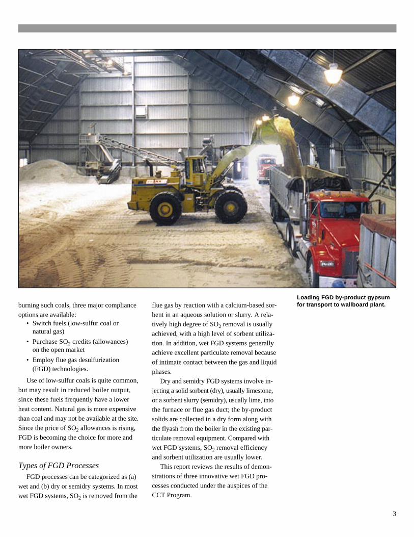
Loading FGD by-product gypsumfor transport to wallboard plant.burning such coals, three major compliance
options are available:• Switch fuels (low-sulfur coal or
natural gas)
• Purchase SO2 credits (allowances)on the open market
• Employ flue gas desulfurization(FGD) technologies.
Use of low-sulfur coals is quite common,
but may result in reduced boiler output,since these fuels frequently have a lower
heat content. Natural gas is more expensive
than coal and may not be available at the site.Since the price of SO2 allowances is rising,
FGD is becoming the choice for more and
more boiler owners.
Types of FGD ProcessesFGD processes can be categorized as (a)
wet and (b) dry or semidry systems. In most
wet FGD systems, SO2 is removed from the
flue gas by reaction with a calcium-based sor-
bent in an aqueous solution or slurry. A rela-tively high degree of SO2 removal is usually
achieved, with a high level of sorbent utiliza-
tion. In addition, wet FGD systems generallyachieve excellent particulate removal because
of intimate contact between the gas and liquid
phases.Dry and semidry FGD systems involve in-
jecting a solid sorbent (dry), usually limestone,
or a sorbent slurry (semidry), usually lime, intothe furnace or flue gas duct; the by-product
solids are collected in a dry form along with
the flyash from the boiler in the existing par-ticulate removal equipment. Compared with
wet FGD systems, SO2 removal efficiency
and sorbent utilization are usually lower.This report reviews the results of demon-
strations of three innovative wet FGD pro-
cesses conducted under the auspices of theCCT Program.
3
Emissions Standards
The Clean Air Act was originally passedin 1970. It was amended in 1977 and most
recently in 1990. The CAAA authorized EPA
to establish new standards for a number ofatmospheric pollutants, including SO2 and
NOx. Periodic review of the emissions
standards every five years is mandated.
SO2 Emissions StandardsUnder Phase II of Title IV, the CAAA
impose significant reductions in SO2 emis-
sions from existing boilers by 2000 andplace an annual cap on emissions beyond
2000. The Phase II allowable SO2 emis-
sions rate is 1.2 lb/million Btu input, downfrom 2.5 lb/million Btu in Phase I.
The CAAA provide for SO2 emissions
allowances (each allowance permits theemission of 1 ton of SO2). As part of a
trading program, allowances can be bought
and sold on the open market. To date,allowance prices have been relatively low,
with the result that many utilities have
opted to purchase allowances insteadof installing FGD systems. However, SO2
allowance prices have been increasing re-
cently, thereby providing the potential fordevelopment of a large-scale retrofit mar-
ket for FGD technologies.
To meet forthcoming emissions regula-tions, especially when burning high-sulfur
coals, it is essential to achieve high levels
of SO2 removal, usually 90% or higher.Even higher levels of SO2 removal can be
beneficial, since this is a way to generate
emissions allowance credits.
Clean Coal TechnologyWet FGDDemonstration Projects
This report discusses three CCT
projects involving innovative wet FGD
technologies:• Advanced Flue Gas Desulfurization
(AFGD) Demonstration Project
• Demonstration of Innovative Applica-tions of Technology for the CT-121
FGD Process
• Milliken Clean Coal TechnologyDemonstration Project
Each of the technologies demonstrated
uses limestone (CaCO3) as a sorbent and iscapable of producing wallboard-grade gyp-
sum as a by-product. A major goal of these
projects was to demonstrate greater than90% SO2 removal at a cost substantially
lower than that of conventional wet FGD
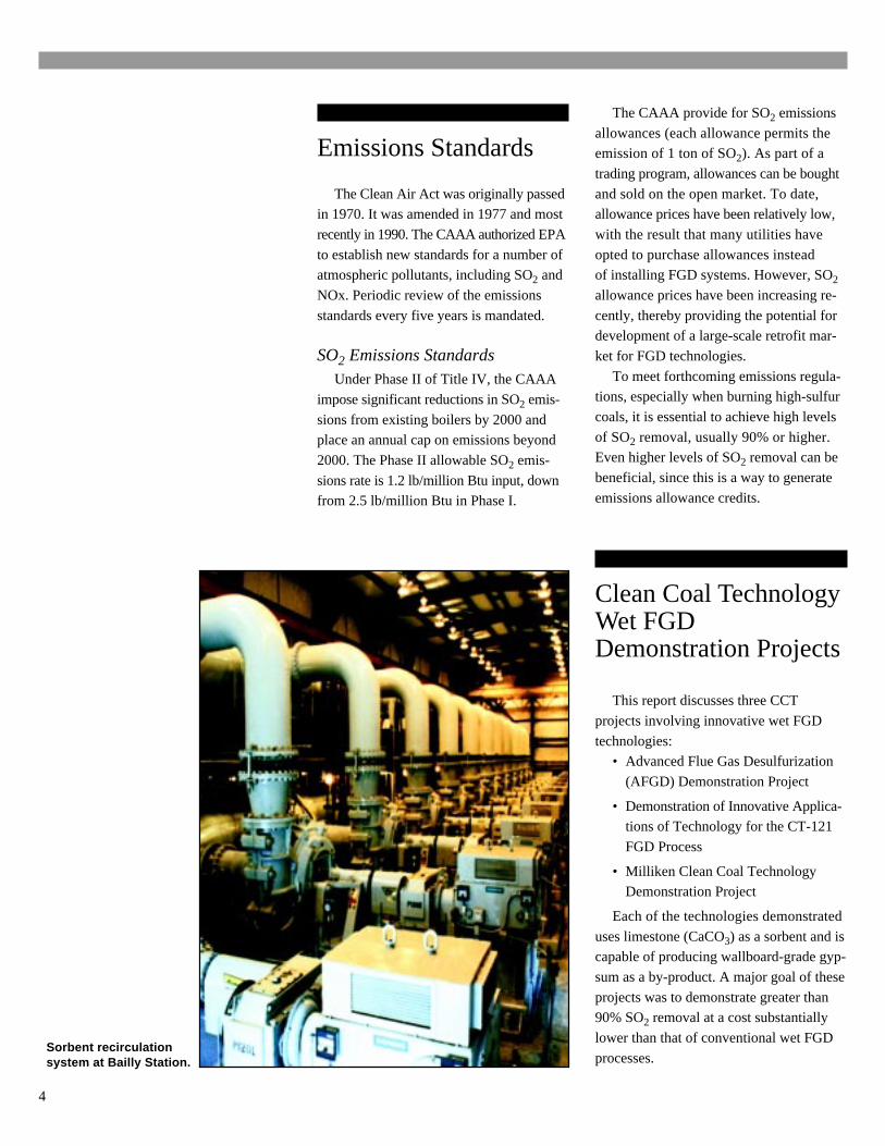
processes.Sorbent recirculationsystem at Bailly Station.
4
Advanced Flue GasDesulfurization (AFGD)Demonstration Project
Project DescriptionThis project was selected during
Round II of DOE’s CCT Program. InDecember 1989, Pure Air on the Lake,
L.P. entered into an agreement to conduct
this demonstration project. Pure Air onthe Lake is a company formed to carry
out this project by Pure Air, a general
partnership between Air Products andChemicals, Inc. and Mitsubishi Heavy
Industries America, Inc.
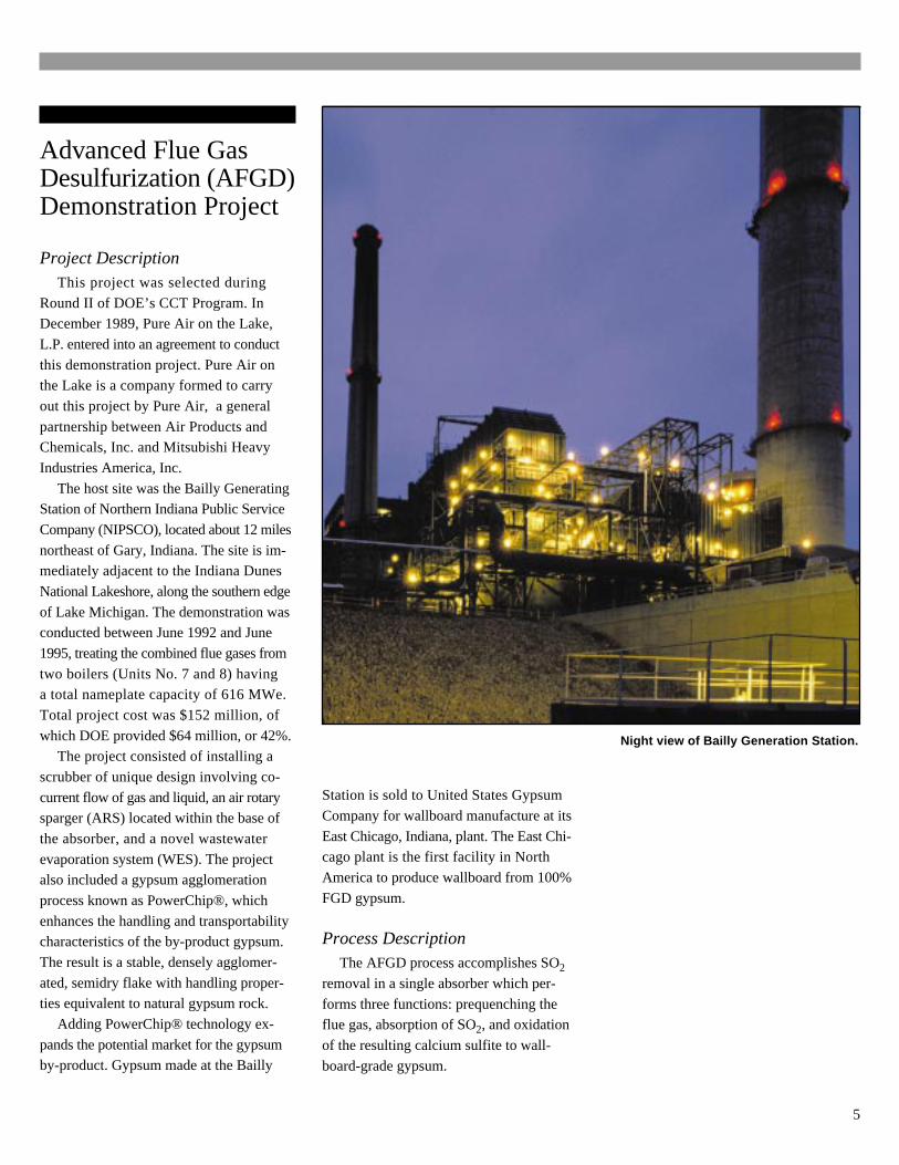
The host site was the Bailly GeneratingStation of Northern Indiana Public Service
Company (NIPSCO), located about 12 miles
northeast of Gary, Indiana. The site is im-mediately adjacent to the Indiana Dunes
National Lakeshore, along the southern edge
of Lake Michigan. The demonstration wasconducted between June 1992 and June
1995, treating the combined flue gases from
two boilers (Units No. 7 and 8) havinga total nameplate capacity of 616 MWe.
Total project cost was $152 million, of
which DOE provided $64 million, or 42%.The project consisted of installing a
scrubber of unique design involving co-
current flow of gas and liquid, an air rotarysparger (ARS) located within the base of
the absorber, and a novel wastewater
evaporation system (WES). The projectalso included a gypsum agglomeration
process known as PowerChip®, which
enhances the handling and transportabilitycharacteristics of the by-product gypsum.
The result is a stable, densely agglomer-
ated, semidry flake with handling proper-ties equivalent to natural gypsum rock.
Adding PowerChip® technology ex-
pands the potential market for the gypsumby-product. Gypsum made at the Bailly
Station is sold to United States Gypsum
Company for wallboard manufacture at its
East Chicago, Indiana, plant. The East Chi-cago plant is the first facility in North
America to produce wallboard from 100%
FGD gypsum.
Process DescriptionThe AFGD process accomplishes SO2
removal in a single absorber which per-
forms three functions: prequenching theflue gas, absorption of SO2, and oxidation
of the resulting calcium sulfite to wall-
board-grade gypsum.
Night view of Bailly Generation Station.
5
Description of theAdvanced Flue Gas Desulfurization (AFGD)
Demonstration Unit at Bailly Station
HotFlueGas
Stack
WastewaterEvaporator Electrostatic
Precipitator
MistEliminator
Water
Water
Air
Air RotarySparger
Dry LimestoneInjection
GypsumCentrifuge
System
Slaked Lime
PolymerGrid
Packing
Gypsum
ToDisposalor Sales
AbsorberRecirculation
DisengagementZone
SlurryReservoir
Absorber
Wastewater
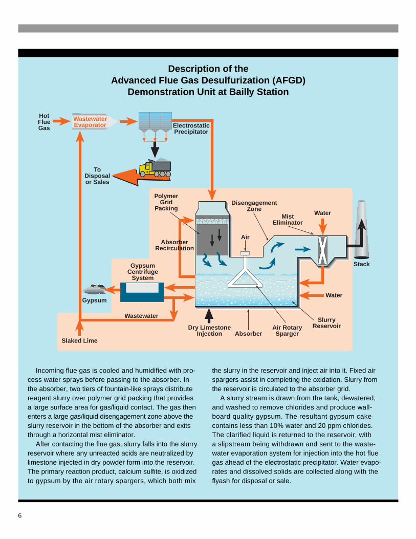
Incoming flue gas is cooled and humidified with pro-cess water sprays before passing to the absorber. Inthe absorber, two tiers of fountain-like sprays distributereagent slurry over polymer grid packing that providesa large surface area for gas/liquid contact. The gas thenenters a large gas/liquid disengagement zone above theslurry reservoir in the bottom of the absorber and exitsthrough a horizontal mist eliminator.
After contacting the flue gas, slurry falls into the slurryreservoir where any unreacted acids are neutralized bylimestone injected in dry powder form into the reservoir.The primary reaction product, calcium sulfite, is oxidizedto gypsum by the air rotary spargers, which both mix
the slurry in the reservoir and inject air into it. Fixed airspargers assist in completing the oxidation. Slurry fromthe reservoir is circulated to the absorber grid.
A slurry stream is drawn from the tank, dewatered,and washed to remove chlorides and produce wall-board quality gypsum. The resultant gypsum cakecontains less than 10% water and 20 ppm chlorides.The clarified liquid is returned to the reservoir, witha slipstream being withdrawn and sent to the waste-water evaporation system for injection into the hot fluegas ahead of the electrostatic precipitator. Water evapo-rates and dissolved solids are collected along with theflyash for disposal or sale.
6
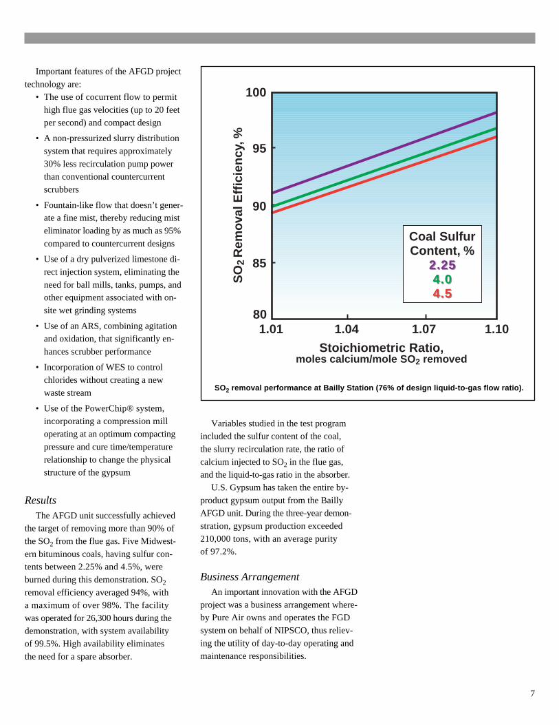
SO2 removal performance at Bailly Station (76% of design liquid-to-gas flow ratio).
Important features of the AFGD project
technology are:• The use of cocurrent flow to permit
high flue gas velocities (up to 20 feet
per second) and compact design
• A non-pressurized slurry distribution
system that requires approximately
30% less recirculation pump powerthan conventional countercurrent
scrubbers
• Fountain-like flow that doesn’t gener-ate a fine mist, thereby reducing mist
eliminator loading by as much as 95%
compared to countercurrent designs
• Use of a dry pulverized limestone di-
rect injection system, eliminating the
need for ball mills, tanks, pumps, andother equipment associated with on-
site wet grinding systems
• Use of an ARS, combining agitationand oxidation, that significantly en-
hances scrubber performance
• Incorporation of WES to controlchlorides without creating a new
waste stream
• Use of the PowerChip® system,incorporating a compression mill
operating at an optimum compacting
pressure and cure time/temperaturerelationship to change the physical
structure of the gypsum
ResultsThe AFGD unit successfully achieved
the target of removing more than 90% of
the SO2 from the flue gas. Five Midwest-
ern bituminous coals, having sulfur con-tents between 2.25% and 4.5%, were
burned during this demonstration. SO2
removal efficiency averaged 94%, witha maximum of over 98%. The facility
was operated for 26,300 hours during the
demonstration, with system availabilityof 99.5%. High availability eliminates
the need for a spare absorber.
Variables studied in the test programincluded the sulfur content of the coal,
the slurry recirculation rate, the ratio of
calcium injected to SO2 in the flue gas,and the liquid-to-gas ratio in the absorber.
U.S. Gypsum has taken the entire by-
product gypsum output from the BaillyAFGD unit. During the three-year demon-
stration, gypsum production exceeded
210,000 tons, with an average purityof 97.2%.
Business ArrangementAn important innovation with the AFGD
project was a business arrangement where-by Pure Air owns and operates the FGD
system on behalf of NIPSCO, thus reliev-
ing the utility of day-to-day operating andmaintenance responsibilities.
100
95
90
85
1.01
SO
2 R
emov
al E
ffici
ency
, %
80
Stoichiometric Ratio,moles calcium/mole SO 2 removed
1.04 1.07 1.10
Inlet SO 2
1000 ppm2500 ppm3500 ppm
Coal SulfurContent, %
2.252.254.04.04.54.5
7
Emissions Standards
History
The Clean Air Act of 1970 estab-lished a major air regulatory role forthe federal government. The Act wasextended by amendments in 1977 andmost recently in 1990. The 1990 CAAAis one of the most complex and com-prehensive pieces of environmentallegislation ever written. It authorizesEPA to establish standards for a num-ber of atmospheric pollutants, includ-ing sulfur dioxide (SO2).
SO2 Emissions Standards
SO2 is formed through the combus-tion of sulfur contained in coal. Burn-ing typical medium- and high-sulfurcoals produces SO2 emissions thatexceed the allowable limits under theCAAA. Two major portions of theCAAA relevant to SO2 control areTitle I and Title IV. Title I establishesNational Ambient Air Quality Stan-dards (NAAQS) for six criteria pol-lutants, including SO2. The 24-houraverage ambient air standard forSO2 under Title I is 0.14 ppm.
Title IV addresses controls for spe-cific types of stationary boilers, includ-ing those found in coal-fired powerplants. Title IV is often referred to asthe Acid Rain Program. The overallgoal of Title IV is to achieve environ-mental and public health benefitsthrough reductions in emissions of SO2
as well as reduced nitrogen oxides(NOx) and particulates emissions.
Title IV uses a two-phase SO2 con-trol strategy. Phase I began in 1995and affects 263 units at 110 mostlycoal-burning electric utility plantslocated in 21 Eastern and Midwestern
states. An additional 182 units joinedthe program as substitution or compen-sating units, bringing the total of PhaseI affected units to 445.
Phase II, which begins January 1,2000, tightens annual emissions limitsand also sets restrictions on smallerplants fired by coal, oil, and gas.The Title IV Phase I SO2 emissionslimit is 2.5 lb/million Btu of heat inputto the boiler. This decreases to 1.2 lb/million Btu in Phase II.
Title IV allows sources to select theirown compliance strategies. To reduceSO2 emissions an affected source mayrepower, use cleaner burning fuel, re-assign some of its energy productionfrom dirtier to cleaner units, or reducefuel consumption by improving effi-ciency. In general, no prior approvalis required, allowing sources to re-spond quickly to market conditions.
The SO2 Trading Allowance Program
The Acid Rain Program representsa dramatic departure from traditionalregulatory methods that establish spe-cific, inflexible, emissions limits withwhich all affected sources must com-ply. Instead, the program introducesan allowance trading system that har-nesses the incentives of the free mar-ket to reduce pollution. Affected utilityunits have been allocated allowancesbased on their historic fuel consump-tion. Each allowance permits a unitto emit one ton of SO2; for eachton of SO2 emitted, one allowanceis retired.
Allowances may be bought, sold,or banked. Anyone may acquire allow-ances and participate in the trading
system. However, regardless of thenumber of allowances held, a sourcemay not emit pollutants at levelsthat would violate federal or statelimits set under Title I of the CAAAto protect public health.
In Phase II, the CAAA set a per-manent ceiling (or cap) of 8.95 mil-lion annual allowances allocatedto utilities. This cap firmly restrictsSO2 emissions and ensures thatenvironmental benefits will beachieved and maintained.
The allowance trading systemcontains an inherent incentive forutilities to reduce pollution, sincefor each ton of SO2 that a utilityavoids emitting, one fewer allowancemust be retired. Utilities that reduceemissions below their allowanceallocation are able to sell, transfer,or bank their surplus allowances.
Title IV includes an optional pro-gram involving voluntary reductionof SO2 emissions. This programallows sources not regulated underTitle IV the opportunity to participateon a voluntary basis, reducing theiremissions and, thereby, receivingSO2 allowances.
EPA invited broad input into thedevelopment of Title IV by consult-ing with representatives from variousstakeholder groups and is maintain-ing this open-door policy as it imple-ments the program. The Acid RainProgram is viewed as a prototype fortackling emerging environmental is-sues. The allowance trading systemcapitalizes on the power of the mar-ketplace to reduce SO2 emissionsin the most cost effective manner.
8
CostsPure Air developed cost estimates for
commercial implementation of the AFGD
technology, covering a range of plant ca-pacities and coal sulfur contents. For a 500-
MWe power plant firing a 3% sulfur coal
and operating at 90% SO2 emissions reduc-tion, the capital cost is estimated at $94/kW.
For a 15-year project life, the levelized cost
on a current dollar basis is 6.5 mills/kWh,which is equivalent to $302/ton of SO2
removed. These costs are about one-half
those of a conventional wet FGD process.The advanced design features of the AFGD
technology result in a comparatively small-
er scrubber, one that requires less plot area,less material to construct, and has much
lower capital and operating costs than con-
ventional scrubbers.
AwardsThe Bailly AFGD project received a 1992
Outstanding Engineering Achievement Award
from the National Society of ProfessionalEngineers and Power magazine’s 1993
Powerplant Award.
ConclusionsThis project shows that a single absorber
can provide flue gas desulfurization for a
power plant of at least 600-MWe capacity
and that no spare absorber is required. It alsoshows that pulverized limestone can be suc-
cessfully injected directly into an absorber.
Wastewater evaporation in the flue gasduct eliminates the need for liquid waste dis-
posal, and use of the gypsum by-product for
wallboard manufacture eliminates the needto dispose of solid waste.
A unique own-and-operate business
arrangement successfully handles theprocessing of flue gas, relieving the host
utility of these responsibilities. The Bailly
AFGD scrubber continues to operatecommercially under a long-term agree-
ment between NIPSCO and Pure Air.
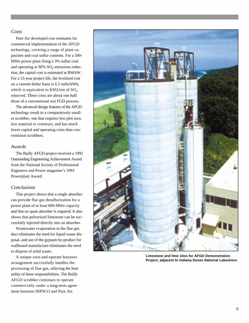
Limestone and lime silos for AFGD DemonstrationProject, adjacent to Indiana Dunes National Lakeshore.
9
The Indiana Dunes
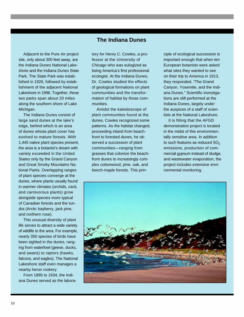
Adjacent to the Pure Air projectsite, only about 300 feet away, arethe Indiana Dunes National Lake-shore and the Indiana Dunes StatePark. The State Park was estab-lished in 1926, followed by estab-lishment of the adjacent NationalLakeshore in 1996. Together, thesetwo parks span about 20 milesalong the southern shore of LakeMichigan.
The Indiana Dunes consist oflarge sand dunes at the lake’sedge, behind which is an areaof dunes whose plant cover hasevolved to mature forests. With1,445 native plant species present,the area is a botanist’s dream withvariety exceeded in the UnitedStates only by the Grand Canyonand Great Smoky Mountains Na-tional Parks. Overlapping rangesof plant species converge at thedunes, where plants usually foundin warmer climates (orchids, cacti,and carnivorous plants) growalongside species more typicalof Canadian forests and the tun-dra (Arctic bayberry, jack pine,and northern rose).
This unusual diversity of plantlife serves to attract a wide varietyof wildlife to the area. For example,nearly 350 species of birds havebeen sighted in the dunes, rang-ing from waterfowl (geese, ducks,and swans) to raptors (hawks,falcons, and eagles). The NationalLakeshore staff even manages anearby heron rookery.
From 1895 to 1934, the Indi-ana Dunes served as the labora-
tory for Henry C. Cowles, a pro-fessor at the University ofChicago who was eulogized asbeing America’s first professionalecologist. At the Indiana Dunes,Dr. Cowles studied the effectsof geological formations on plantcommunities and the transfor-mation of habitat by those com-munities.
Amidst the kaleidoscope ofplant communities found at thedunes, Cowles recognized somepatterns. As the habitat changed,proceeding inland from beach-front to forested dunes, he ob-served a succession of plantcommunities—ranging fromgrasses that colonize the beach-front dunes to increasingly com-plex cottonwood, pine, oak, andbeech-maple forests. This prin-
ciple of ecological succession isimportant enough that when tenEuropean botanists were askedwhat sites they wanted to seeon their trip to America in 1913,they responded, “The GrandCanyon, Yosemite, and the Indi-ana Dunes.” Scientific investiga-tions are still performed at theIndiana Dunes, largely underthe auspices of a staff of scien-tists at the National Lakeshore.
It is fitting that the AFGDdemonstration project is locatedin the midst of this environmen-tally sensitive area. In additionto such features as reduced SO2
emissions, production of com-mercial gypsum instead of sludge,and wastewater evaporation, theproject includes extensive envi-ronmental monitoring.
10
Demonstration ofInnovative Applicationsof Technology for theCT-121 FGD Process
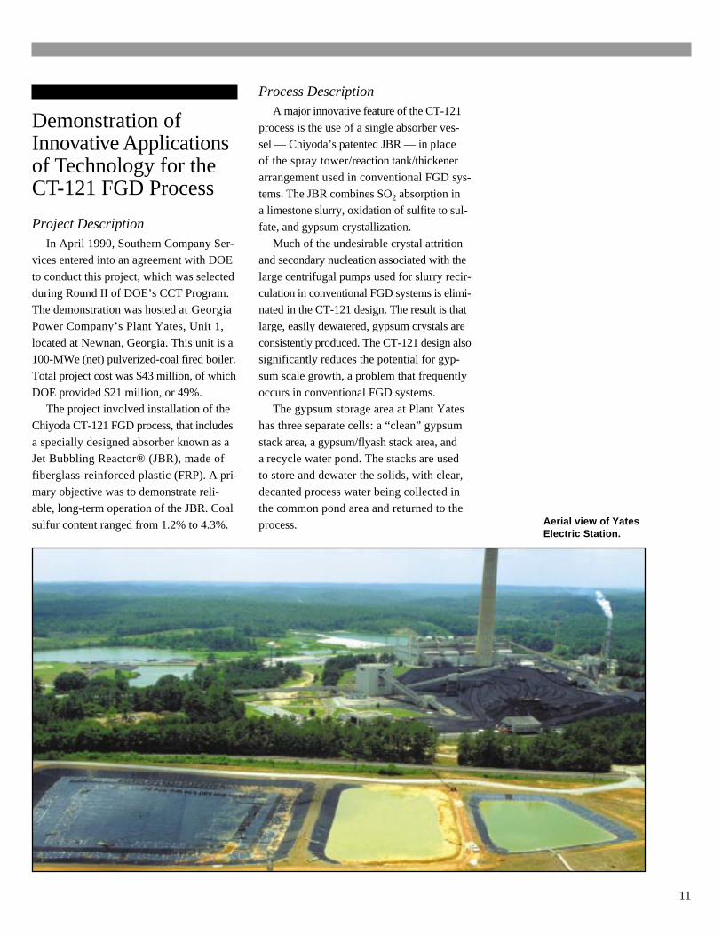
Project DescriptionIn April 1990, Southern Company Ser-
vices entered into an agreement with DOE
to conduct this project, which was selected
during Round II of DOE’s CCT Program.The demonstration was hosted at Georgia
Power Company’s Plant Yates, Unit 1,
located at Newnan, Georgia. This unit is a100-MWe (net) pulverized-coal fired boiler.
Total project cost was $43 million, of which
DOE provided $21 million, or 49%.The project involved installation of the
Chiyoda CT-121 FGD process, that includes
a specially designed absorber known as aJet Bubbling Reactor® (JBR), made of
fiberglass-reinforced plastic (FRP). A pri-
mary objective was to demonstrate reli-able, long-term operation of the JBR. Coal
sulfur content ranged from 1.2% to 4.3%.
Process DescriptionA major innovative feature of the CT-121
process is the use of a single absorber ves-
sel — Chiyoda’s patented JBR — in placeof the spray tower/reaction tank/thickener
arrangement used in conventional FGD sys-
tems. The JBR combines SO2 absorption ina limestone slurry, oxidation of sulfite to sul-
fate, and gypsum crystallization.
Much of the undesirable crystal attritionand secondary nucleation associated with the
large centrifugal pumps used for slurry recir-
culation in conventional FGD systems is elimi-nated in the CT-121 design. The result is that
large, easily dewatered, gypsum crystals are
consistently produced. The CT-121 design alsosignificantly reduces the potential for gyp-
sum scale growth, a problem that frequently
occurs in conventional FGD systems.The gypsum storage area at Plant Yates
has three separate cells: a “clean” gypsum
stack area, a gypsum/flyash stack area, anda recycle water pond. The stacks are used
to store and dewater the solids, with clear,
decanted process water being collected inthe common pond area and returned to the
process. Aerial view of YatesElectric Station.
11
Overview
Most SO2 control technologiesinvolve the addition of a calcium-based sorbent to the system. Underthe proper conditions, this materialreacts with SO2 to form calcium sul-fite (CaSO3), which is then oxidizedto calcium sulfate (CaSO4). Be-cause of their low cost, limestoneand lime are the most frequentlyused sorbents.
In the majority of applications,the sorbent is dissolved in, or slur-ried with, water; flue gas contactsthe solution or slurry in a scrubber.Alternatively, the sorbent is inject-ed directly into the furnace or fluegas duct.
Historical Note
The notion of scrubbing SO2 fromcoal-derived flue gas dates back tothe 1920s and 30s, when the firstscrubbers were built in Great Brit-ain. These facilities were shut downduring World War II so that the Brit-ish power plants would not be de-tected by aircraft that could followthe vapor plumes. Interestingly, eventhese first scrubbers were capableof removing 90% of the SO2. Scrub-ber technology continued to evolvethrough the 1960s, with installationsin Europe, Japan, and the United
States. However, widespread applica-tion in the United States did not occuruntil enactment of the Clean Air Actof 1970.
In the United States, a number ofcoal-fired power plants were equippedwith scrubbers during the 1970s andearly 1980s. These scrubbers were,for the most part, installed at newlyconstructed power plants, becauseexisting plants were exempt underthe law. When domestic power plantconstruction decreased in the 1980s,the market for scrubber technologymoved overseas, where improvementswere made. With the advent of acidrain controls for older units underthe 1990 Clean Air Act Amendments(CAAA), a new market for scrubbertechnology began to emerge in theUnited States. Technology develop-ments continue to improve perfor-mance and reduce costs.
Dry and Semidry Sorbent Injection
A reactive calcium- or sodium-basedsorbent is injected into the economizeror flue gas duct, where the particlesreact with SO2 and are subsequentlyremoved along with flyash by theboiler’s particulate control device. Thetwo most common calcium-based sor-bents are limestone, CaCO3, and slak-ed lime, Ca(OH)2. Limestone, which
generally requires a higher reactiontemperature, is usually injected as adry powder. Lime, on the other hand,is usually handled as a slurry thatdries as soon as it is injected intothe hot flue gas.
This is referred to as semidryscrubbing, which dominates the sor-bent injection market. All commer-cial semidry systems in the U.S.use lime and recycled fly ash assorbent. These systems account for8-10% of the installed FGD capacityin the U.S.
Sulfuric Acid Production
Although less commonly used,another approach is to oxidize theSO2 to SO3 over a catalyst and ab-sorb it in water to form sulfuric acid,which can be sold for a variety ofuses, such as metals pickling.
Conventional Wet FGDTechnology
Conventional wet FGD systemsare typically designed for SO2 re-moval efficiencies of about 90%,a level required to meet air qualitystandards when burning high-sulfurcoals.
The processing scheme for mostwet FGD systems is essentially asfollows. Flue gas from the particulate
SO2 Emissions Control Technologies
12

collector flows to the SO2 absorber,the energy necessary to overcomethe FGD system pressure dropbeing provided by the boiler induceddraft (ID) fans. In the absorber, avariety of technology specific de-vices achieve intimate contact ofthe flue gas with the sorbent slurry.Gas flow per unit cross sectionalarea, which determines scrubberdiameter, must be low enough tominimize entrainment. Mass transfercharacteristics of the system deter-mine absorber height. Absorber ves-sels tend to be quite large in practice.
Following contact with the slurry,the scrubbed flue gas passes throughmist eliminators, which remove en-trained slurry droplets. Periodic wash-ing using fresh water keeps the misteliminators clean and provides make-up water to the FGD system.
In the absorber, SO2 reacts withlimestone, forming calcium sulfite.Limestone is supplied either as adry solid or a slurry. The sulfite issubsequently oxidized in a separatereaction tank to form calcium sul-fate, which crystallizes as gypsum(CaSO4 • 2H2O). The residence timeof solids in the reaction tank is gen-erally in the range of 15 to 25 hours.This extended residence time, coupl-ed with proper reaction tank design
and operation, provides an environ-ment conducive to gypsum crystalgrowth.
In some processes, pumps recircu-late slurry from the reaction tank tothe scrubber to provide the volume ofslurry necessary to maintain good gas/slurry contact and ensure high SO2 re-moval efficiency. The slurry in the re-cycle tank is agitated to maintain thesolids in suspension and prevent sol-ids buildup on the tank bottom.
A small slipstream of slurry is sentto a primary dewatering system,which recovers solids (gypsum andflyash). The dewatering system isdesigned to concentrate the gypsumcrystals to an ultimate solids contentof 85% to 90% (dewatered gypsumhas the consistency of wet sand). Thegypsum is conveyed to an on-sitewaste disposal landfill or shipped toa processing facility where the by-product gypsum is utilized for wall-board or cement manufacture.
Recovered process water is re-turned to the absorption and reagentpreparation systems.
Over its life, a 500-MWe coal-firedpower plant with a conventional wetscrubber produces enough sludge tofill a 500-acre disposal pond 40 feetdeep. Early scrubbers were plaguedby poor reliability, often requiring the
installation of spare modules asback-up to ensure continuous fluegas cleanup.
Innovative Wet FGD Technology
The innovative scrubbers de-scribed in this report are a signifi-cant improvement over 1970s wetscrubber technology, featuringstate-of-the-art designs and materi-als of construction. Highly efficient,compact, and less expensive toconstruct and operate, these scrub-bers eliminate waste disposal prob-lems by incorporating oxidation ofthe calcium sulfite sludge to wall-board-grade gypsum. Because ofhigh process reliability, spare scrub-ber modules are not required.
Advanced features developedin these CCT projects have beenwidely adopted by scrubber ven-dors and, more importantly, theU.S. electric utility industry. Thesedemonstration projects have re-sulted in increased competition,pointing the scrubber market to-ward fewer but larger absorbervessels, salable by-products, andbetter equipment guarantees. Theresultant savings to U.S. electricitycustomers amount to billions ofdollars in reduced costs forCAAA compliance.
13
Description of the CT-121 Process Demonstration Unit at Plant Yates
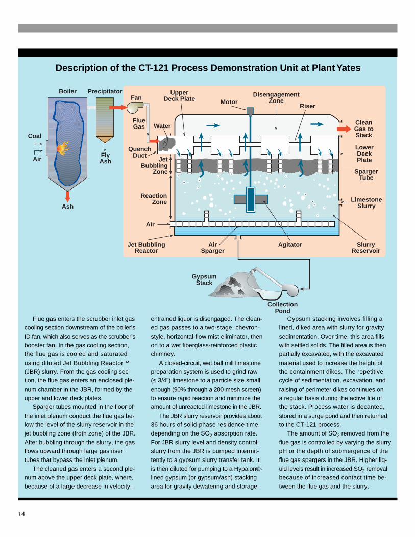
Flue gas enters the scrubber inlet gascooling section downstream of the boiler’s
ID fan, which also serves as the scrubber’sbooster fan. In the gas cooling section,the flue gas is cooled and saturated
using diluted Jet Bubbling Reactor™(JBR) slurry. From the gas cooling sec-tion, the flue gas enters an enclosed ple-
num chamber in the JBR, formed by theupper and lower deck plates.
Sparger tubes mounted in the floor of
the inlet plenum conduct the flue gas be-low the level of the slurry reservoir in thejet bubbling zone (froth zone) of the JBR.
After bubbling through the slurry, the gasflows upward through large gas risertubes that bypass the inlet plenum.
The cleaned gas enters a second ple-num above the upper deck plate, where,because of a large decrease in velocity,
entrained liquor is disengaged. The clean-ed gas passes to a two-stage, chevron-
style, horizontal-flow mist eliminator, thenon to a wet fiberglass-reinforced plasticchimney.
A closed-circuit, wet ball mill limestonepreparation system is used to grind raw(≤ 3/4") limestone to a particle size small
enough (90% through a 200-mesh screen)to ensure rapid reaction and minimize theamount of unreacted limestone in the JBR.
The JBR slurry reservoir provides about36 hours of solid-phase residence time,depending on the SO2 absorption rate.
For JBR slurry level and density control,slurry from the JBR is pumped intermit-tently to a gypsum slurry transfer tank. It
is then diluted for pumping to a Hypalon®-lined gypsum (or gypsum/ash) stackingarea for gravity dewatering and storage.
Gypsum stacking involves filling alined, diked area with slurry for gravity
sedimentation. Over time, this area fillswith settled solids. The filled area is thenpartially excavated, with the excavated
material used to increase the height ofthe containment dikes. The repetitivecycle of sedimentation, excavation, and
raising of perimeter dikes continues ona regular basis during the active life ofthe stack. Process water is decanted,
stored in a surge pond and then returnedto the CT-121 process.
The amount of SO2 removed from the
flue gas is controlled by varying the slurrypH or the depth of submergence of theflue gas spargers in the JBR. Higher liq-
uid levels result in increased SO2 removalbecause of increased contact time be-tween the flue gas and the slurry.
Water
UpperDeck Plate
Riser
CleanGas toStack
Motor
LowerDeckPlate
LimestoneSlurry
AgitatorAirSparger
Air
ReactionZone
JetBubbling
Zone
QuenchDuct
Fan
FlueGas
FlyAsh
PrecipitatorBoiler
Ash
Air
Coal
SpargerTube
CollectionPond
GypsumStack
Jet BubblingReactor
SlurryReservoir
DisengagementZone
14
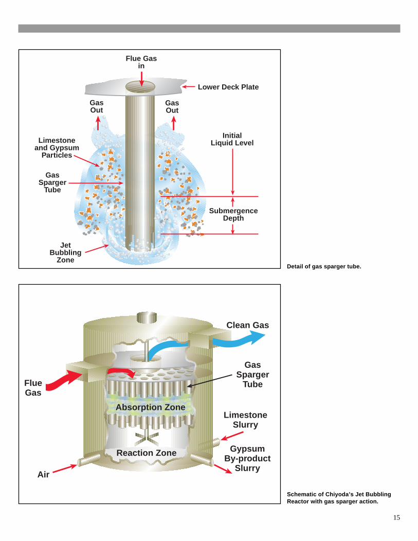
Schematic of Chiyoda’s Jet BubblingReactor with gas sparger action.
Absorption Zone
Reaction Zone
Air
GypsumBy-product
Slurry
LimestoneSlurry
Clean Gas
FlueGas
GasSparger
Tube
Lower Deck Plate
Flue Gasin
GasOut
GasOut
InitialLiquid Level
SubmergenceDepth
GasSparger
Tube
JetBubbling
Zone
Limestoneand Gypsum
Particles
Detail of gas sparger tube.
15
ResultsWhen high-sulfur coal was burned
at maximum boiler load at Plant Yates,
the CT-121 scrubber exceeded the target90% SO2 removal efficiency and dem-
onstrated excellent availability. Lime-
stone utilization was greater than 97%.Maximum SO2 removal was about 98%
when burning 2.2% sulfur coal, and
about 95% with 3.5% sulfur coal. Sinceremoval efficiency is controlled by ad-
justing the depth of submergence of the
flue gas spargers, it is relatively simpleto compensate for the higher sulfur con-
tent, thereby maintaining SO2 removal
efficiency.
Materials of ConstructionAs indicated previously, one of the
novel aspects of the CT-121 design is
the use of fiberglass-reinforced plasticto avoid the corrosion damage associ-
ated with traditional closed-loop FGD
systems. Both the JBR and the inlettransition duct, where flue gas is cooled
prior to contacting the sparger tubes,
are made completely of FRP. A distinctadvantage of this construction is that it
eliminates the need for a flue gas pre-
scrubber, traditionally included in FGDsystems to remove chlorides that cause
serious corrosion in alloys.
Exposed surfaces at Plant Yateswere coated with homogeneous filler
materials (Duromar® and Duromix®)
to protect against erosion. The use ofFRP was very successful; this material
proved to be durable both structurally
and chemically. The chimney resistedcorrosion from condensates in the wet
flue gas, thereby precluding the need
for flue gas reheat. The high reliabilityverified that a spare absorber is not
necessary.
SO2 Formation and Removal
Combustion
All coals contain sulfur. Some of this sulfur, known as organic sulfur, is inti-mately associated with the coal matrix. The rest of the sulfur, in the form ofpyrites or sulfates, is associated with the mineral matter. High-sulfur bitumi-nous coals contain up to about 4% sulfur, whereas low-sulfur Western coalsmay have a sulfur content below 1%.
Upon combustion, most of the sulfur is converted to SO2, with a smallamount being further oxidized to sulfur trioxide (SO3).
S(Coal) + O2 ----> SO2
SO2 + 1/2 O2 ----> SO3
Because, in the absence of a catalyst, the formation of SO3 is slow, over98% of the combusted sulfur is in the form of SO2.
Effective January 1, 2000, the SO2 emissions limit for coal-fired powerplants is 1.2 lb/million Btu. To comply with this regulation without FGD, themaximum sulfur content for a coal having a higher heating value of 12,000Btu/lb is 0.72% by weight, assuming 100% conversion of sulfur to SO2.
Wet FGD
The major reactions occurring in wet FGD processes are shown by the fol-lowing equations:
Absorption
SO2 + H2O ----> H2SO3
SO3 + H2O ----> H2SO4
Neutralization
CaCO3 + H2SO3 ----> CaSO3 + CO2 + H2OCaCO3 + H2SO4 ----> CaSO4 + CO2 + H2O
Oxidation
CaSO3 + 1/2 O2 ----> CaSO4
Crystallization
CaSO4 + 2H2O ----> CaSO4 • 2H2O
16
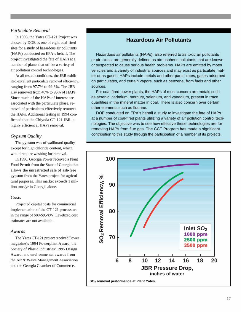
SO2 removal performance at Plant Yates.
Particulate RemovalIn 1993, the Yates CT-121 Project was
chosen by DOE as one of eight coal-fired
sites for a study of hazardous air pollutants(HAPs) conducted on EPA’s behalf. The
project investigated the fate of HAPs at a
number of plants that utilize a variety ofair pollution control technologies.
At all tested conditions, the JBR exhib-
ited excellent particulate removal efficiency,ranging from 97.7% to 99.3%. The JBR
also removed from 40% to 95% of HAPs.
Since much of the HAPs of interest areassociated with the particulate phase, re-
moval of particulates effectively removes
the HAPs. Additional testing in 1994 con-firmed that the Chiyoda CT-121 JBR is
highly efficient at HAPs removal.
Gypsum QualityThe gypsum was of wallboard quality
except for high chloride content, which
would require washing for removal.
In 1996, Georgia Power received a PlantFood Permit from the State of Georgia that
allows the unrestricted sale of ash-free
gypsum from the Yates project for agricul-tural purposes. This market exceeds 1 mil-
lion tons/yr in Georgia alone.
CostsProjected capital costs for commercial
implementation of the CT-121 process are
in the range of $80-$95/kW. Levelized cost
estimates are not available.
AwardsThe Yates CT-121 project received Power
magazine’s 1994 Powerplant Award, the
Society of Plastic Industries’ 1995 DesignAward, and environmental awards from
the Air & Waste Management Association
and the Georgia Chamber of Commerce.
Hazardous Air Pollutants
Hazardous air pollutants (HAPs), also referred to as toxic air pollutantsor air toxics, are generally defined as atmospheric pollutants that are knownor suspected to cause serious health problems. HAPs are emitted by motorvehicles and a variety of industrial sources and may exist as particulate mat-ter or as gases. HAPs include metals and other particulates, gases adsorbedon particulates, and certain vapors, such as benzene, from fuels and othersources.
For coal-fired power plants, the HAPs of most concern are metals suchas arsenic, cadmium, mercury, selenium, and vanadium, present in tracequantities in the mineral matter in coal. There is also concern over certainother elements such as fluorine.
DOE conducted on EPA’s behalf a study to investigate the fate of HAPsat a number of coal-fired plants utilizing a variety of air pollution control tech-nologies. The objective was to see how effective these technologies are forremoving HAPs from flue gas. The CCT Program has made a significantcontribution to this study through the participation of a number of its projects.
100
90
80
70
6 8 10 12 14 16 18 20
Inlet SO 2
1000 ppm2500 ppm3500 ppm
JBR Pressure Drop,inches of water
Inlet SO 21000 ppm1000 ppm2500 ppm2500 ppm3500 ppm3500 ppm
SO
2 R
emov
al E
ffici
ency
, %
17
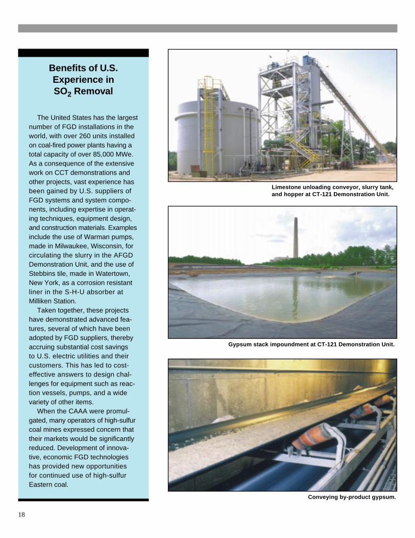
Gypsum stack impoundment at CT-121 Demonstration Unit.
Conveying by-product gypsum.
Benefits of U.S.Experience inSO2 Removal
The United States has the largestnumber of FGD installations in theworld, with over 260 units installedon coal-fired power plants having atotal capacity of over 85,000 MWe.As a consequence of the extensivework on CCT demonstrations andother projects, vast experience hasbeen gained by U.S. suppliers ofFGD systems and system compo-nents, including expertise in operat-ing techniques, equipment design,and construction materials. Examplesinclude the use of Warman pumps,made in Milwaukee, Wisconsin, forcirculating the slurry in the AFGDDemonstration Unit, and the use ofStebbins tile, made in Watertown,New York, as a corrosion resistantliner in the S-H-U absorber atMilliken Station.
Taken together, these projectshave demonstrated advanced fea-tures, several of which have beenadopted by FGD suppliers, therebyaccruing substantial cost savingsto U.S. electric utilities and theircustomers. This has led to cost-effective answers to design chal-lenges for equipment such as reac-tion vessels, pumps, and a widevariety of other items.
When the CAAA were promul-gated, many operators of high-sulfurcoal mines expressed concern thattheir markets would be significantlyreduced. Development of innova-tive, economic FGD technologieshas provided new opportunitiesfor continued use of high-sulfurEastern coal.
Limestone unloading conveyor, slurry tank,and hopper at CT-121 Demonstration Unit.
18
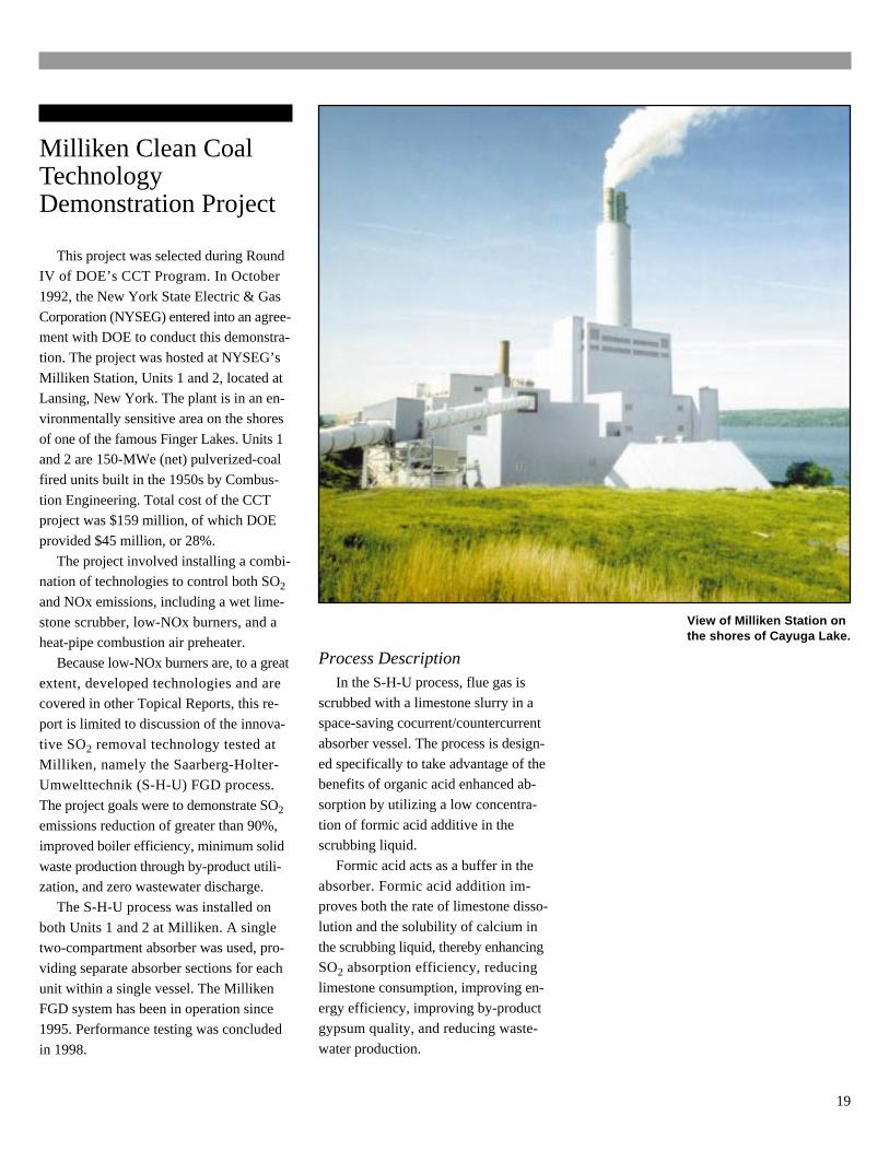
Milliken Clean CoalTechnologyDemonstration Project
This project was selected during RoundIV of DOE’s CCT Program. In October
1992, the New York State Electric & Gas
Corporation (NYSEG) entered into an agree-ment with DOE to conduct this demonstra-
tion. The project was hosted at NYSEG’s
Milliken Station, Units 1 and 2, located atLansing, New York. The plant is in an en-
vironmentally sensitive area on the shores
of one of the famous Finger Lakes. Units 1and 2 are 150-MWe (net) pulverized-coal
fired units built in the 1950s by Combus-
tion Engineering. Total cost of the CCTproject was $159 million, of which DOE
provided $45 million, or 28%.
The project involved installing a combi-nation of technologies to control both SO2
and NOx emissions, including a wet lime-
stone scrubber, low-NOx burners, and aheat-pipe combustion air preheater.
Because low-NOx burners are, to a great
extent, developed technologies and arecovered in other Topical Reports, this re-
port is limited to discussion of the innova-
tive SO2 removal technology tested atMilliken, namely the Saarberg-Holter-
Umwelttechnik (S-H-U) FGD process.
The project goals were to demonstrate SO2
emissions reduction of greater than 90%,
improved boiler efficiency, minimum solid
waste production through by-product utili-zation, and zero wastewater discharge.
The S-H-U process was installed on
both Units 1 and 2 at Milliken. A singletwo-compartment absorber was used, pro-
viding separate absorber sections for each
unit within a single vessel. The MillikenFGD system has been in operation since
1995. Performance testing was concluded
in 1998.
View of Milliken Station onthe shores of Cayuga Lake.
Process DescriptionIn the S-H-U process, flue gas is
scrubbed with a limestone slurry in aspace-saving cocurrent/countercurrent
absorber vessel. The process is design-
ed specifically to take advantage of thebenefits of organic acid enhanced ab-
sorption by utilizing a low concentra-
tion of formic acid additive in thescrubbing liquid.
Formic acid acts as a buffer in the
absorber. Formic acid addition im-proves both the rate of limestone disso-
lution and the solubility of calcium in
the scrubbing liquid, thereby enhancingSO2 absorption efficiency, reducing
limestone consumption, improving en-
ergy efficiency, improving by-productgypsum quality, and reducing waste-
water production.
19
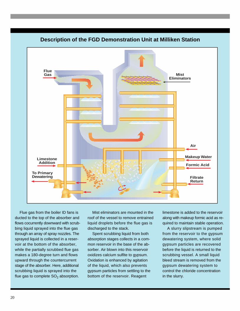
Description of the FGD Demonstration Unit at Milliken Station
Flue gas from the boiler ID fans isducted to the top of the absorber andflows cocurrently downward with scrub-bing liquid sprayed into the flue gasthrough an array of spray nozzles. Thesprayed liquid is collected in a reser-voir at the bottom of the absorber,while the partially scrubbed flue gasmakes a 180-degree turn and flowsupward through the countercurrentstage of the absorber. Here, additionalscrubbing liquid is sprayed into theflue gas to complete SO2 absorption.
Mist eliminators are mounted in theroof of the vessel to remove entrainedliquid droplets before the flue gas isdischarged to the stack.
Spent scrubbing liquid from bothabsorption stages collects in a com-mon reservoir in the base of the ab-sorber. Air blown into this reservoiroxidizes calcium sulfite to gypsum.Oxidation is enhanced by agitationof the liquid, which also preventsgypsum particles from settling to thebottom of the reservoir. Reagent
limestone is added to the reservoiralong with makeup formic acid as re-quired to maintain stable operation.
A slurry slipstream is pumpedfrom the reservoir to the gypsumdewatering system, where solidgypsum particles are recoveredbefore the liquid is returned to thescrubbing vessel. A small liquidbleed stream is removed from thegypsum dewatering system tocontrol the chloride concentrationin the slurry.
FlueGas Mist
Eliminators
Formic Acid
Air
LimestoneAddition
Makeup Water
To PrimaryDewatering Filtrate
Return
20
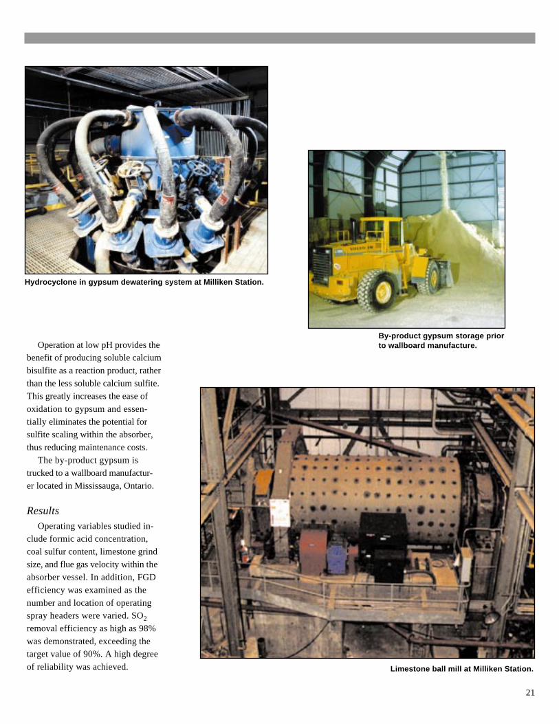
Limestone ball mill at Milliken Station.
Hydrocyclone in gypsum dewatering system at Milliken Station.
Operation at low pH provides thebenefit of producing soluble calcium
bisulfite as a reaction product, rather
than the less soluble calcium sulfite.This greatly increases the ease of
oxidation to gypsum and essen-
tially eliminates the potential forsulfite scaling within the absorber,
thus reducing maintenance costs.
The by-product gypsum istrucked to a wallboard manufactur-
er located in Mississauga, Ontario.
ResultsOperating variables studied in-
clude formic acid concentration,
coal sulfur content, limestone grind
size, and flue gas velocity within theabsorber vessel. In addition, FGD
efficiency was examined as the
number and location of operatingspray headers were varied. SO2
removal efficiency as high as 98%
was demonstrated, exceeding thetarget value of 90%. A high degree
of reliability was achieved.
By-product gypsum storage priorto wallboard manufacture.
21
Performance testing has demonstrated
the beneficial effect of formic acid en-hanced operation. In one series of tests,
SO2 removal efficiency increased from
83% without formic acid to 95% with for-mic acid. At the same removal efficiency,
using formic acid results in a 75% reduc-
tion in energy required for circulating thesorbent slurry.
Materials of ConstructionSpecial consideration was given to the
materials of construction of the absorberto minimize erosion and corrosion, which
have caused problems with some conven-
tional FGD systems. The absorber shell isconstructed of reinforced concrete with an
integral, cast-in-place liner made of Stebbins
ceramic tile. This tile has superior abrasionand corrosion resistance compared to rub-
ber and alloy linings and is expected to last
for the life of the plant.
CostsProjected economics for commercial
implementation of the S-H-U process have
been prepared by NYSEG. For a 300-MWepower plant burning 3.2% sulfur coal, the
total capital requirement for an S-H-U
retrofit with 95% SO2 removal is $300/kW. Assuming a 15-year project life, the
levelized cost on a current dollar basis is
12.0 mills/kWh, which is equivalent to$534/ton of SO2 removed.
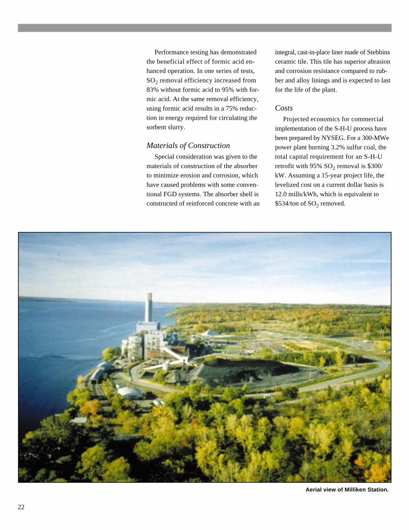
Aerial view of Milliken Station.
22
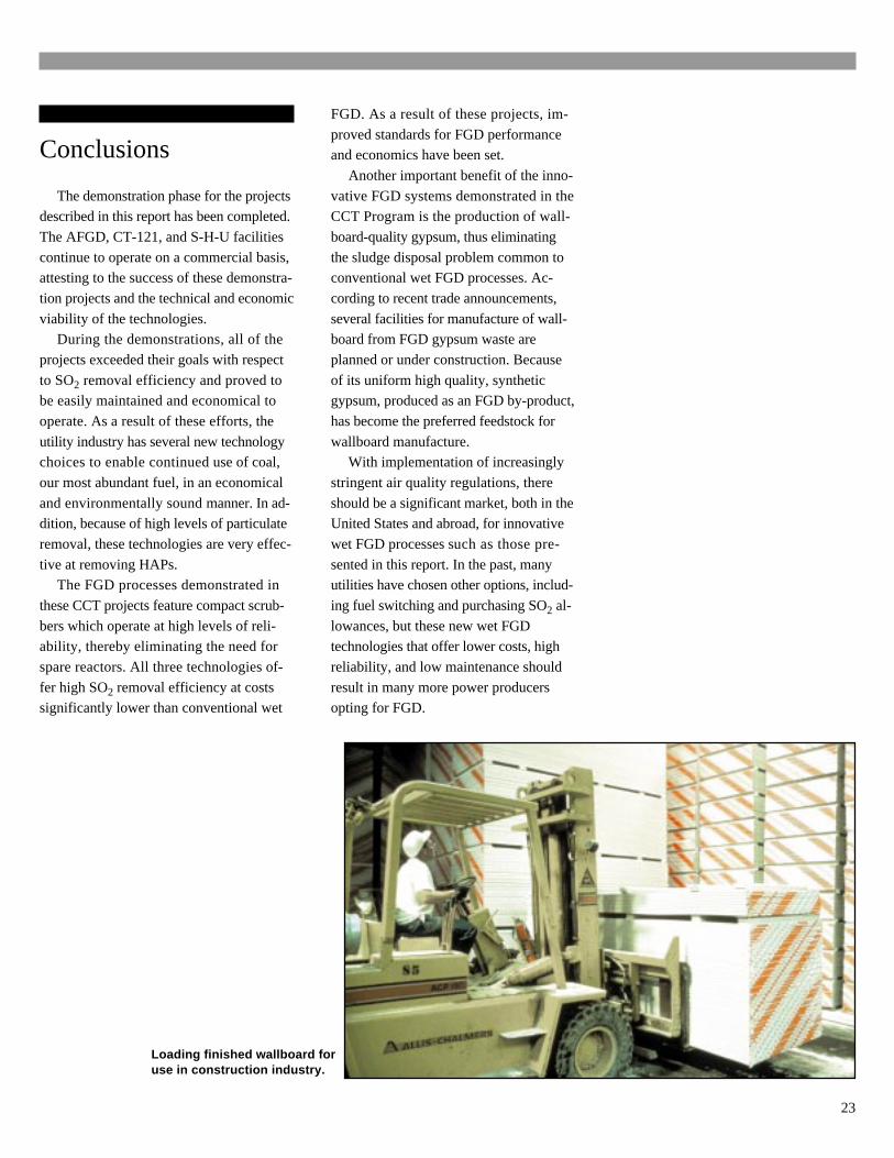
Loading finished wallboard foruse in construction industry.
Conclusions
The demonstration phase for the projectsdescribed in this report has been completed.
The AFGD, CT-121, and S-H-U facilities
continue to operate on a commercial basis,attesting to the success of these demonstra-
tion projects and the technical and economic
viability of the technologies.During the demonstrations, all of the
projects exceeded their goals with respect
to SO2 removal efficiency and proved tobe easily maintained and economical to
operate. As a result of these efforts, the
utility industry has several new technologychoices to enable continued use of coal,
our most abundant fuel, in an economical
and environmentally sound manner. In ad-dition, because of high levels of particulate
removal, these technologies are very effec-
tive at removing HAPs.The FGD processes demonstrated in
these CCT projects feature compact scrub-
bers which operate at high levels of reli-ability, thereby eliminating the need for
spare reactors. All three technologies of-
fer high SO2 removal efficiency at costssignificantly lower than conventional wet
FGD. As a result of these projects, im-
proved standards for FGD performanceand economics have been set.
Another important benefit of the inno-
vative FGD systems demonstrated in theCCT Program is the production of wall-
board-quality gypsum, thus eliminating
the sludge disposal problem common toconventional wet FGD processes. Ac-
cording to recent trade announcements,
several facilities for manufacture of wall-board from FGD gypsum waste are
planned or under construction. Because
of its uniform high quality, syntheticgypsum, produced as an FGD by-product,
has become the preferred feedstock for
wallboard manufacture.With implementation of increasingly
stringent air quality regulations, there
should be a significant market, both in theUnited States and abroad, for innovative
wet FGD processes such as those pre-
sented in this report. In the past, manyutilities have chosen other options, includ-
ing fuel switching and purchasing SO2 al-
lowances, but these new wet FGDtechnologies that offer lower costs, high
reliability, and low maintenance should
result in many more power producersopting for FGD.
23
Bibliography
Pure Air/AFGD
Comprehensive Report to Congress, Clean
Coal Technology Program, “AdvancedFlue Gas Desulfurization (AFGD) Demon-
stration Project,” proposed by Pure Air,
U.S. DOE, November 1989.
R.J. Keeth, P.J. Ireland, and P.T. Radcliffe,
“Economic Evaluation of 28 FGD Pro-cesses,” 1991 EPRI/EPA/DOE SO2 Con-
trol Symposium (Washington DC),
December 1991.
B. Wrobel and D.C. Vymazal, “Acid Rain
Compliance -- Advanced Co-Current WetFGD Design for the Bailly Station,” First
Annual Clean Coal Technology Confer-
ence (Cleveland OH), September 1992.
B. Wrobel and D.C. Vymazal, “Acid Rain
Compliance -- Advanced Co-Current WetFGD Design for the Bailly Station,” AWMA
Annual Meeting (Denver CO), June 1993.
P.M. Ashline, “A Case Study: The Com-
mercial Deployment of Pure Air’s Clean
Coal Technology,” Second Annual Clean
Coal Technology Conference (Atlanta
GA), September 1993.
J. Henderson, D.C. Vymazal, D.A. Stryf,
and T.A. Sarkus, “Two Years of Outstand-
ing AFGD Performance -- Pure Air on theLake’s Bailly Scrubber Facility,” Third
Annual Clean Coal Technology Confer-
ence (Chicago IL), September 1994.
G.B. Manavizadeh, J.J. Lewnard, D.A.
Stryf, and T.A. Sarkus, “Bailly StationAFGD Demonstration Program,” Fourth
Annual Clean Coal Technology Confer-
ence (Denver CO), September 1995.
Radian Corporation, “Plume Opacity Mod-
eling of NIPSCO Bailly Unit 7 and 8 Stackwith May 1995 Data,” November 1995.
D.C. Vymazal, G.B. Manavizadeh, andD.W. Smith, “Economic and Environmen-
tal Benefits of Advanced Flue-Gas Des-
ulfurization Technology -- Three Years ofDOE Test Results,” American Power Con-
ference (Chicago IL), April 1996.
Final Report, “Volume 2, Project Perfor-
mance and Economics,” Pure Air, April
1996.
Chiyoda CT-121
Comprehensive Report to Congress, CleanCoal Technology Program, “Demonstra-
tion of Innovative Applications of Tech-
nology for the CT-121 FGD Process,”proposed by Southern Company Services,
U.S. DOE, February 1990.
D.P. Burford, O.W. Hargrove, and H.J.
Ritz, “Demonstration of Innovative Appli-
cations of Technology for the CT-121FGD Process,” First Annual Clean Coal
Technology Conference (Cleveland OH),
September 1992.
D.P. Burford, “Chiyoda Thoroughbred 121
Innovative Clean Coal Technology Dem-onstration Project -- Initial Testing Re-
sults,” Second Annual Clean Coal
Technology Conference (Atlanta GA),September 1993.
D.P. Burford, I.G. Pearl, and H.J. Ritz,“CT-121 Scrubber Demonstration Mid-
Project Performance Results,” Third An-
nual Clean Coal Technology Conference
(Chicago IL), September 1994.
I.G. Pearl, “Chiyoda Thoroughbred 121Phase II Demonstration Results,” Fourth
Annual Clean Coal Technology Confer-
ence (Denver CO), September 1995.
D.P. Burford, “Chiyoda Thoroughbred CT-
121 Clean Coal Project at Georgia Power’sPlant Yates -- Phase II Results,” Fifth An-
nual Clean Coal Technology Conference
(Tampa FL), January 1997.
Milliken/S-H-U
Comprehensive Report to Congress, CleanCoal Technology Program, “Milliken
Clean Coal Technology Demonstration
Project,” proposed by New York StateElectric & Gas Corporation, U.S. DOE,
September 1992.
M.E. Mahlmeister, J.E. Hofman, R.M.
Statnick, C.E. Jackson, G.G. Elia, J.
Glamser, and R.E. Aliasso, “Overviewof the Milliken Clean Coal Technology
Demonstration Project,” First Annual
Clean Coal Technology Conference
(Cleveland OH), September 1992.
D.T. O’Dea, C.E. Jackson, and G.G. Elia,“Milliken Station Demonstration Project
FGD Retrofit Update,” Third Annual
Clean Coal Technology Conference (Chi-cago IL), September 1994.
E.S. Baron, G. Gaufillet, and C.E. Jackson,“Milliken Station Demonstration Project
FGD Retrofit Update - 1995,” Fourth An-
nual Clean Coal Technology Conference
(Denver CO), September 1995.
James Harvilla, Sharon Burns, WalterSavichky, Mark Mahlmeister, and James
Watts, “Milliken Clean Coal Technology
Demonstration Project,” Sixth Clean Coal
Technology Conference (Reno NV), April
1998.
Final Report, “Project Performance and
Economics Report,” New York State Elec-
tric & Gas Corporation, April 1999.
24
The Clean Coal Technology Program
The Clean Coal Technology (CCT)Program is a unique partnership be-tween the federal government andindustry that has as its primary goalthe successful introduction of newclean coal utilization technologiesinto the energy marketplace. Withits roots in the acid rain debate ofthe 1980s, the program has met itsobjective of broadening the rangeof technological solutions availableto eliminate acid rain concernsassociated with coal use.
Moreover, the CCT Programhas evolved and been expandedto address the need for new, high-efficiency power-generating tech-nologies that will allow coal to con-tinue to be a fuel option well intothe 21st century.
Begun in 1985 and expanded in1987 consistent with the recommen-dation of the U.S. and Canadian
Special Envoys on Acid Rain, theCCT Program has been implement-ed through a series of five nation-wide competitive solicitations. Eachsolicitation has been associatedwith specific government fundingand program objectives. After fivesolicitations, the CCT Programcomprises a total of 40 projectslocated in 18 states with a capitalinvestment value of nearly $6 bil-lion. DOE’s share of the total pro-ject costs is about $2 billion, orapproximately 34% of the total.The projects’ industrial participants(i.e., the non-DOE participants) areproviding the remainder — nearly$4 billion.
Technologies being demonstrat-ed under the CCT Program are es-tablishing a technology base that willenable the nation to meet more strin-gent energy and environmental
goals. Most of the demonstrationsare being conducted at commercialscale, in actual user environments,and under circumstances typicalof commercial operations. Thesefeatures allow the potential of thetechnologies to be evaluated intheir intended commercial applica-tions. Each application addressesone of the following four marketsectors:
• Advanced electric powergeneration
• Environmental control devices• Coal processing for clean
fuels• Industrial applicationsGiven its programmatic success,
the CCT Program serves as a modelfor other cooperative government/industry programs aimed at introduc-ing new technologies into the com-mercial marketplace.
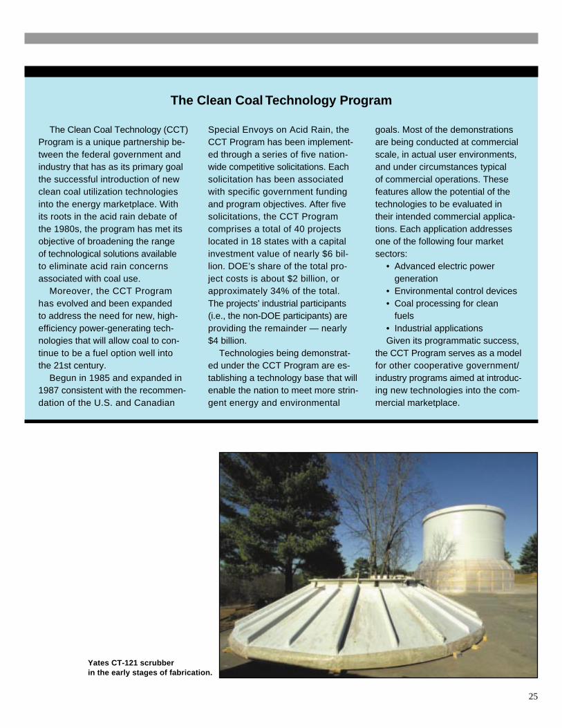
Yates CT-121 scrubberin the early stages of fabrication.
25
This report is available on the Internetat U.S. DOE, Office of Fossil Energy’s home page: www.fe.doe.gov
To ReceiveAdditional
Information
To be placed on the Department ofEnergy’s distribution list for future in-formation on the Clean Coal Tech-nology Program, the demonstrationprojects it is financing, or other Fos-sil Energy Programs, contact:
Robert C. Porter, DirectorOffice of CommunicationU.S. Department of EnergyFE-51000 Independence Ave SWWashington DC 20585(202) 586-6503(202) 586-5146 [email protected]
Otis MillsPublic Information OfficeU.S. Department of EnergyFederal Energy Technology CenterP.O. Box 10940Pittsburgh PA 15236-0940(412) 386-5890(412) 386-6195 [email protected]
Contacts for CCT Projectand U.S. DOE CCT Program
Southern Company Services, Inc.
ContactDavid P. BurfordProject ManagerSouthern Company Services, Inc.P.O. Box 2625Birmingham AL 35202-2625(205) 992-6329(205) 992-7535 [email protected]
Pure Air on the Lake, L.P.
ContactTim RothAsset ManagerPure Air on the Lake, L.P.7201 Hamilton Blvd.Allentown PA 18195-1501(610) 481-6257(610) 481-5444 [email protected]
New York State Electric & GasCorporation
ContactJames HarvillaProject ManagerNew York State Electric & Gas CorporationCorporate Drive - Kirkwood Industrial ParkP.O. Box 5224Binghamton NY 13902-2551(607) 762-8630(607) 762-8457 [email protected]
U.S. Department of Energy
ContactsDavid J. BeecyDirector, Office of Environmental Systems TechnologyFE 23, GTN, Room D-212Germantown MD 20874-1290(301) 903-2787(301) 903-8350 [email protected]
James U. WattsProject ManagerFederal Energy Technology CenterP.O. Box 10940Pittsburgh PA 15236-0940(412) 386-5991(412) 386-4775 [email protected]
26
List of Acronyms and Abbreviations
AFGD ........................................................................ Advanced Flue Gas Desulfurization
ARS ........................................................................................................ Air rotary sparger
Btu ........................................................................................................British thermal unit
CAAA ....................................................................... Clean Air Act Amendments of 1990
CaCO3...........................................................................................................Calcium carbonate (limestone)
CaO ....................................................................................................Calcium oxide (lime)
Ca(OH)2...................................................................................................Calcium hydroxide (slaked lime)
CaSO3 .............................................................................................................................................Calcium sulfite
CaSO4 ............................................................................................................................................Calcium sulfate
CaSO4•2H2O .......................................................................................................... gypsum
CCT ............................................................................................... Clean Coal Technology
CO2 .................................................................................................................................................Carbon dioxide
DOE ......................................................................................... U.S. Department of Energy
EPA ...................................................................... U.S. Environmental Protection Agency
ESP .............................................................................................. Electrostatic precipitator
FETC .......................................................................... Federal Energy Technology Center
FGD .............................................................................................. Flue gas desulfurization
FRP ........................................................................................ Fiberglass-reinforced plastic
HAPs ............................................................................................Hazardous air pollutants
ID .................................................................................................................... Induced draft
JBR ................................................................................................. Jet Bubbling Reactor®
H2SO4 ..................................................................................................................................................Sulfuric acid
kW .......................................................................................................................... kilowatt
kWh ................................................................................................................ kilowatt hour
MWe ...................................................................................... Megawatts of electric power
NAAQS ..............................................................National Ambient Air Quality Standards
NIPSCO .......................................................... Northern Indiana Public Service Company
NOx ........................................................................................................... Nitrogen oxides
NSPS ......................................................................... New Source Performance Standards
NYSEG .........................................................New York State Electric & Gas Corporation
ppm ........................................................................................................... parts per million
S-H-U .............................................................................. Saarberg-Holter-Umwelttechnik
SO2 .....................................................................................................................................................Sulfur dioxide
SO3 ....................................................................................................................................................Sulfur trioxide
SR ........................................................................................................ Stoichiometric ratio
WES.................................................................................. Wastewater evaporation system
27