Embed Size (px)
Citation preview
Advanced Routing
FortiOS™ Handbook v3
for FortiOS 4.0 MR3
FortiOS™ Handbook Advanced Routing
v3
4 January 2013
01-433-98043-20120116
Copyright© 2012 Fortinet, Inc. All rights reserved. Fortinet®, FortiGate®, and
FortGuard®, are registered trademarks of Fortinet, Inc., and other Fortinet names herein
may also be trademarks of Fortinet. All other product or company names may be
trademarks of their respective owners. Performance metrics contained herein were
attained in internal lab tests under ideal conditions, and performance may vary. Network
variables, different network environments and other conditions may affect performance
results. Nothing herein represents any binding commitment by Fortinet, and Fortinet
disclaims all warranties, whether express or implied, except to the extent Fortinet enters
a binding written contract, signed by Fortinet’s General Counsel, with a purchaser that
expressly warrants that the identified product will perform according to the performance
metrics herein. For absolute clarity, any such warranty will be limited to performance in
the same ideal conditions as in Fortinet’s internal lab tests. Fortinet disclaims in full any
guarantees. Fortinet reserves the right to change, modify, transfer, or otherwise revise this
publication without notice, and the most current version of the publication shall be
applicable.
Visit these links for more information and documentation for your Fortinet products:
Fortinet Knowledge Base - http://kb.fortinet.com
Technical Documentation - http://docs.fortinet.com
Training Services - http://campus.training.fortinet.com
Technical Support - http://support.fortinet.com
You can report errors or omissions in this or any Fortinet technical document to
F o r t i O S H a n d b o o k
F
0
h
Contents
Introduction 11
Before you begin . . . . . . . . . . . . . . . . . . . . . . . . . . . . . . . . . . . . 11
How this guide is organized . . . . . . . . . . . . . . . . . . . . . . . . . . . . . . 11
Advanced Static routing 13
Routing concepts. . . . . . . . . . . . . . . . . . . . . . . . . . . . . . . . . . . . 13
Routing in VDOMs . . . . . . . . . . . . . . . . . . . . . . . . . . . . . . . . . 13
Default route . . . . . . . . . . . . . . . . . . . . . . . . . . . . . . . . . . . . 14
Routing table . . . . . . . . . . . . . . . . . . . . . . . . . . . . . . . . . . . . 14
Viewing the routing table in the web-based manager . . . . . . . . . . . . . 15
Viewing the routing table in the CLI . . . . . . . . . . . . . . . . . . . . . . 18
Searching the routing table . . . . . . . . . . . . . . . . . . . . . . . . . . 19
Building the routing table . . . . . . . . . . . . . . . . . . . . . . . . . . . . . 20
Static routing security . . . . . . . . . . . . . . . . . . . . . . . . . . . . . . . 21
Network Address Translation (NAT) . . . . . . . . . . . . . . . . . . . . . . 21
Access Control List (ACL) . . . . . . . . . . . . . . . . . . . . . . . . . . . 22
Blackhole Route . . . . . . . . . . . . . . . . . . . . . . . . . . . . . . . . 22
Reverse path lookup . . . . . . . . . . . . . . . . . . . . . . . . . . . . . . 23
Multipath routing and determining the best route . . . . . . . . . . . . . . . . . 23
Route priority . . . . . . . . . . . . . . . . . . . . . . . . . . . . . . . . . . . 24
Troubleshooting static routing . . . . . . . . . . . . . . . . . . . . . . . . . . . 25
Ping . . . . . . . . . . . . . . . . . . . . . . . . . . . . . . . . . . . . . . 25
Traceroute . . . . . . . . . . . . . . . . . . . . . . . . . . . . . . . . . . . 26
Examine routing table contents . . . . . . . . . . . . . . . . . . . . . . . . 26
ECMP route failover and load balancing . . . . . . . . . . . . . . . . . . . . . . . . 27
Equal-Cost Multi-Path (ECMP) . . . . . . . . . . . . . . . . . . . . . . . . . . . 27
ECMP routing of simultaneous sessions to the same destination IP address 28
Priority and ECMP . . . . . . . . . . . . . . . . . . . . . . . . . . . . . . . . . 28
Configuring interface status detection for gateway load balancing . . . . . . . . 29
Configuring spillover or usage-based ECMP . . . . . . . . . . . . . . . . . . . 31
Detailed description of how spill-over ECMP selects routes . . . . . . . . . 32
Determining if an interface has exceeded its Spillover Threshold . . . . . . . 33
Configuring weighted static route load balancing . . . . . . . . . . . . . . . . . 33
Static routing tips. . . . . . . . . . . . . . . . . . . . . . . . . . . . . . . . . . . . 34
Policy routing . . . . . . . . . . . . . . . . . . . . . . . . . . . . . . . . . . . . . . 35
Adding a policy route. . . . . . . . . . . . . . . . . . . . . . . . . . . . . . . . 36
Example policy route. . . . . . . . . . . . . . . . . . . . . . . . . . . . . . 37
Type of Service . . . . . . . . . . . . . . . . . . . . . . . . . . . . . . . . 37
Moving a policy route . . . . . . . . . . . . . . . . . . . . . . . . . . . . . . . 38
ortiOS™ Handbook v3: Advanced Routing
1-433-98043-20120116 3
ttp://docs.fortinet.com/
Contents
Transparent mode static routing . . . . . . . . . . . . . . . . . . . . . . . . . . . . 38
Dynamic Routing Overview 41
What is dynamic routing? . . . . . . . . . . . . . . . . . . . . . . . . . . . . . . . 41
Comparing static and dynamic routing . . . . . . . . . . . . . . . . . . . . . . 41
Dynamic routing protocols . . . . . . . . . . . . . . . . . . . . . . . . . . . . . 42
Classful versus classless routing protocols . . . . . . . . . . . . . . . . . . 42
Interior versus exterior routing protocols . . . . . . . . . . . . . . . . . . . 43
Distance vector versus link-state protocols . . . . . . . . . . . . . . . . . . 43
Minimum configuration for dynamic routing . . . . . . . . . . . . . . . . . . . . 44
Comparison of dynamic routing protocols . . . . . . . . . . . . . . . . . . . . . . . 44
Features of dynamic routing protocols. . . . . . . . . . . . . . . . . . . . . . . 44
Routing protocols . . . . . . . . . . . . . . . . . . . . . . . . . . . . . . . 45
Routing algorithm . . . . . . . . . . . . . . . . . . . . . . . . . . . . . . . 45
Authentication . . . . . . . . . . . . . . . . . . . . . . . . . . . . . . . . . 46
Convergence. . . . . . . . . . . . . . . . . . . . . . . . . . . . . . . . . . 46
IPv6 Support . . . . . . . . . . . . . . . . . . . . . . . . . . . . . . . . . . 46
When to adopt dynamic routing . . . . . . . . . . . . . . . . . . . . . . . . . . 47
Budget . . . . . . . . . . . . . . . . . . . . . . . . . . . . . . . . . . . . . 47
Current network size and topology . . . . . . . . . . . . . . . . . . . . . . 47
Expected network growth . . . . . . . . . . . . . . . . . . . . . . . . . . . 48
Available resources for ongoing maintenance. . . . . . . . . . . . . . . . . 48
Choosing a routing protocol . . . . . . . . . . . . . . . . . . . . . . . . . . . . 49
Answer questions about your network . . . . . . . . . . . . . . . . . . . . 49
Evaluate your chosen protocol . . . . . . . . . . . . . . . . . . . . . . . . 50
Implement your dynamic routing protocol . . . . . . . . . . . . . . . . . . . 50
Dynamic routing terminology . . . . . . . . . . . . . . . . . . . . . . . . . . . . . . 50
Aggregated routes and addresses. . . . . . . . . . . . . . . . . . . . . . . 50
Autonomous system (AS) . . . . . . . . . . . . . . . . . . . . . . . . . . . 51
Area border router (ABR). . . . . . . . . . . . . . . . . . . . . . . . . . . . 53
Neighbor routers . . . . . . . . . . . . . . . . . . . . . . . . . . . . . . . . 53
Route maps . . . . . . . . . . . . . . . . . . . . . . . . . . . . . . . . . . 53
Access lists . . . . . . . . . . . . . . . . . . . . . . . . . . . . . . . . . . 54
Bi-directional forwarding detection (BFD) . . . . . . . . . . . . . . . . . . . 54
IPv6 in dynamic routing . . . . . . . . . . . . . . . . . . . . . . . . . . . . . . . . 55
Routing Information Protocol (RIP) 57
RIP background and concepts . . . . . . . . . . . . . . . . . . . . . . . . . . . . . 57
Background . . . . . . . . . . . . . . . . . . . . . . . . . . . . . . . . . . . . 57
RIP v1 . . . . . . . . . . . . . . . . . . . . . . . . . . . . . . . . . . . . . 57
RIP v2 . . . . . . . . . . . . . . . . . . . . . . . . . . . . . . . . . . . . . 58
RIPng . . . . . . . . . . . . . . . . . . . . . . . . . . . . . . . . . . . . . 58
Parts and terminology of RIP. . . . . . . . . . . . . . . . . . . . . . . . . . . . 58
RIP and IPv6 . . . . . . . . . . . . . . . . . . . . . . . . . . . . . . . . . . 58
Default information originate option . . . . . . . . . . . . . . . . . . . . . . 59
Advanced Routing for FortiOS 4.0 MR3
4 01-433-98043-20120116
http://docs.fortinet.com/
Contents
F
0
h
Garbage, timeout, and update timers . . . . . . . . . . . . . . . . . . . . . 59
Authentication and key-chain . . . . . . . . . . . . . . . . . . . . . . . . . 60
Access Lists . . . . . . . . . . . . . . . . . . . . . . . . . . . . . . . . . . 61
How RIP works . . . . . . . . . . . . . . . . . . . . . . . . . . . . . . . . . . . 63
RIP versus static routing . . . . . . . . . . . . . . . . . . . . . . . . . . . . 63
RIP metric — hop count . . . . . . . . . . . . . . . . . . . . . . . . . . . . 63
The Bellman–Ford routing algorithm. . . . . . . . . . . . . . . . . . . . . . 64
Passive versus active RIP interfaces . . . . . . . . . . . . . . . . . . . . . 66
RIP packet structure . . . . . . . . . . . . . . . . . . . . . . . . . . . . . . 67
Troubleshooting RIP . . . . . . . . . . . . . . . . . . . . . . . . . . . . . . . . . . 68
Routing Loops . . . . . . . . . . . . . . . . . . . . . . . . . . . . . . . . . . . 68
Routing loops’ effect on the network . . . . . . . . . . . . . . . . . . . . . 68
How can you spot a routing loop . . . . . . . . . . . . . . . . . . . . . . . 68
Action to take on discovering a routing loop . . . . . . . . . . . . . . . . . 71
Split horizon and Poison reverse updates . . . . . . . . . . . . . . . . . . . . . 71
Debugging IPv6 on RIPng . . . . . . . . . . . . . . . . . . . . . . . . . . . . . 71
RIP routing examples. . . . . . . . . . . . . . . . . . . . . . . . . . . . . . . . . . 72
Simple RIP example . . . . . . . . . . . . . . . . . . . . . . . . . . . . . . . . . . 72
Network layout and assumptions . . . . . . . . . . . . . . . . . . . . . . . . . 72
Basic network layout. . . . . . . . . . . . . . . . . . . . . . . . . . . . . . 72
Assumptions . . . . . . . . . . . . . . . . . . . . . . . . . . . . . . . . . . 74
General configuration steps . . . . . . . . . . . . . . . . . . . . . . . . . . . . 74
Configuring the FortiGate units system information . . . . . . . . . . . . . . . . 74
Configure the hostname, interfaces, and default route . . . . . . . . . . . . 75
Configuring FortiGate unit RIP router information . . . . . . . . . . . . . . . . . 82
Configuring other networking devices . . . . . . . . . . . . . . . . . . . . . . . 86
Testing network configuration . . . . . . . . . . . . . . . . . . . . . . . . . . . 86
RIPng — RIP and IPv6 . . . . . . . . . . . . . . . . . . . . . . . . . . . . . . . . . 86
Network layout and assumptions . . . . . . . . . . . . . . . . . . . . . . . . . 87
Basic network layout. . . . . . . . . . . . . . . . . . . . . . . . . . . . . . 87
Assumptions . . . . . . . . . . . . . . . . . . . . . . . . . . . . . . . . . . 88
General configuration steps . . . . . . . . . . . . . . . . . . . . . . . . . . . . 88
Configuring the FortiGate units system information . . . . . . . . . . . . . . . . 88
Configuring RIPng on FortiGate units . . . . . . . . . . . . . . . . . . . . . . . 91
Configuring other network devices. . . . . . . . . . . . . . . . . . . . . . . . . 92
Testing the configuration. . . . . . . . . . . . . . . . . . . . . . . . . . . . . . 92
Testing the IPv6 RIPng information . . . . . . . . . . . . . . . . . . . . . . 92
Border Gateway Protocol (BGP) 93
BGP background and concepts . . . . . . . . . . . . . . . . . . . . . . . . . . . . 93
Background. . . . . . . . . . . . . . . . . . . . . . . . . . . . . . . . . . . . . . . 93
Parts and terminology of BGP . . . . . . . . . . . . . . . . . . . . . . . . . . . . . 93
BGP and IPv6 . . . . . . . . . . . . . . . . . . . . . . . . . . . . . . . . . . . 94
Roles of routers in BGP networks . . . . . . . . . . . . . . . . . . . . . . . . . 94
ortiOS™ Handbook v3: Advanced Routing
1-433-98043-20120116 5
ttp://docs.fortinet.com/
Contents
Speaker routers . . . . . . . . . . . . . . . . . . . . . . . . . . . . . . . . 95
Peer routers or neighbors . . . . . . . . . . . . . . . . . . . . . . . . . . . 95
Route reflectors (RR). . . . . . . . . . . . . . . . . . . . . . . . . . . . . . 97
Confederations . . . . . . . . . . . . . . . . . . . . . . . . . . . . . . . . . . . 98
Network Layer Reachability Information (NLRI) . . . . . . . . . . . . . . . . . . 99
BGP attributes . . . . . . . . . . . . . . . . . . . . . . . . . . . . . . . . . . . 99
AS_PATH . . . . . . . . . . . . . . . . . . . . . . . . . . . . . . . . . . . 99
MULTI_EXIT_DESC (MED) . . . . . . . . . . . . . . . . . . . . . . . . . . . 100
COMMUNITY . . . . . . . . . . . . . . . . . . . . . . . . . . . . . . . . . 100
NEXT_HOP. . . . . . . . . . . . . . . . . . . . . . . . . . . . . . . . . . . 101
ATOMIC_AGGREGATE . . . . . . . . . . . . . . . . . . . . . . . . . . . . 101
ORIGIN. . . . . . . . . . . . . . . . . . . . . . . . . . . . . . . . . . . . . 101
How BGP works . . . . . . . . . . . . . . . . . . . . . . . . . . . . . . . . . . . . 102
IBGP versus EBGP . . . . . . . . . . . . . . . . . . . . . . . . . . . . . . . . . 102
BGP path determination — which route to use . . . . . . . . . . . . . . . . . . 102
Decision phase 1. . . . . . . . . . . . . . . . . . . . . . . . . . . . . . . . 103
Decision phase 2. . . . . . . . . . . . . . . . . . . . . . . . . . . . . . . . 104
Decision phase 3. . . . . . . . . . . . . . . . . . . . . . . . . . . . . . . . 104
Aggregate routes and addresses . . . . . . . . . . . . . . . . . . . . . . . 104
Troubleshooting BGP. . . . . . . . . . . . . . . . . . . . . . . . . . . . . . . . . . 105
Clearing routing table entries . . . . . . . . . . . . . . . . . . . . . . . . . . . 105
Route flap . . . . . . . . . . . . . . . . . . . . . . . . . . . . . . . . . . . . . 105
Holddown timer . . . . . . . . . . . . . . . . . . . . . . . . . . . . . . . . 106
Dampening. . . . . . . . . . . . . . . . . . . . . . . . . . . . . . . . . . . 107
Graceful restart . . . . . . . . . . . . . . . . . . . . . . . . . . . . . . . . 107
Bi-directional forwarding detection (BFD) . . . . . . . . . . . . . . . . . . . 108
BGP routing examples . . . . . . . . . . . . . . . . . . . . . . . . . . . . . . . . . 109
Dual-homed BGP example . . . . . . . . . . . . . . . . . . . . . . . . . . . . . . . 109
Why dual home? . . . . . . . . . . . . . . . . . . . . . . . . . . . . . . . . 110
Potential dual homing issues . . . . . . . . . . . . . . . . . . . . . . . . . 110
Network layout and assumptions . . . . . . . . . . . . . . . . . . . . . . . . . 111
Network layout . . . . . . . . . . . . . . . . . . . . . . . . . . . . . . . . . 111
Assumptions . . . . . . . . . . . . . . . . . . . . . . . . . . . . . . . . . . 112
General configuration steps . . . . . . . . . . . . . . . . . . . . . . . . . . . . 112
Configuring the FortiGate unit . . . . . . . . . . . . . . . . . . . . . . . . . . . 113
Configure interfaces and default routes . . . . . . . . . . . . . . . . . . . . 113
Configure firewall services, addresses, and policies . . . . . . . . . . . . . 115
Set the FortiGate BGP information . . . . . . . . . . . . . . . . . . . . . . 119
Add the internal network to the AS . . . . . . . . . . . . . . . . . . . . . . 119
Additional FortiGate BGP configuration . . . . . . . . . . . . . . . . . . . . 120
Configuring other networking devices . . . . . . . . . . . . . . . . . . . . . . . 121
Testing this configuration . . . . . . . . . . . . . . . . . . . . . . . . . . . . . 121
Testing network connectivity . . . . . . . . . . . . . . . . . . . . . . . . . 121
Verifying the FortiGate unit’s routing tables . . . . . . . . . . . . . . . . . . 122
Verifying traffic routing . . . . . . . . . . . . . . . . . . . . . . . . . . . . . 122
Advanced Routing for FortiOS 4.0 MR3
6 01-433-98043-20120116
http://docs.fortinet.com/
Contents
F
0
h
Verifying the dual-homed side of the configuration . . . . . . . . . . . . . . 122
Redistributing and blocking routes in BGP. . . . . . . . . . . . . . . . . . . . . . . 123
Network layout and assumptions . . . . . . . . . . . . . . . . . . . . . . . . . 123
Network layout . . . . . . . . . . . . . . . . . . . . . . . . . . . . . . . . . 123
Assumptions . . . . . . . . . . . . . . . . . . . . . . . . . . . . . . . . . . 124
General Configuration Steps. . . . . . . . . . . . . . . . . . . . . . . . . . 124
Configuring the FortiGate unit — networks and firewalls . . . . . . . . . . . 124
Configuring the FortiGate unit - BGP . . . . . . . . . . . . . . . . . . . . . 127
Configuring the FortiGate unit - OSPF. . . . . . . . . . . . . . . . . . . . . 128
Configuring other networking devices . . . . . . . . . . . . . . . . . . . . . 129
Testing network configuration . . . . . . . . . . . . . . . . . . . . . . . . . 129
Open Shortest Path First (OSPF) 131
OSPF Background and concepts . . . . . . . . . . . . . . . . . . . . . . . . . . . 131
Background . . . . . . . . . . . . . . . . . . . . . . . . . . . . . . . . . . . . 131
The parts and terminology of OSPF . . . . . . . . . . . . . . . . . . . . . . . . 131
OSPF and IPv6. . . . . . . . . . . . . . . . . . . . . . . . . . . . . . . . . 132
Router ID . . . . . . . . . . . . . . . . . . . . . . . . . . . . . . . . . . . . 132
Adjacency . . . . . . . . . . . . . . . . . . . . . . . . . . . . . . . . . . . 132
Designated router (DR) and backup router (BDR) . . . . . . . . . . . . . . . 133
Area . . . . . . . . . . . . . . . . . . . . . . . . . . . . . . . . . . . . . . 134
Authentication . . . . . . . . . . . . . . . . . . . . . . . . . . . . . . . . . 135
Hello and dead intervals . . . . . . . . . . . . . . . . . . . . . . . . . . . . 136
Access Lists . . . . . . . . . . . . . . . . . . . . . . . . . . . . . . . . . . 137
How OSPF works . . . . . . . . . . . . . . . . . . . . . . . . . . . . . . . . . 138
OSPF router discovery. . . . . . . . . . . . . . . . . . . . . . . . . . . . . 138
How OSPF works on FortiGate units . . . . . . . . . . . . . . . . . . . . . 139
External routes . . . . . . . . . . . . . . . . . . . . . . . . . . . . . . . . . 139
Link-state Database (LSDB) and route updates . . . . . . . . . . . . . . . . 140
OSPF packets . . . . . . . . . . . . . . . . . . . . . . . . . . . . . . . . . 142
Troubleshooting OSPF . . . . . . . . . . . . . . . . . . . . . . . . . . . . . . . . . 143
Clearing OSPF routes from the routing table . . . . . . . . . . . . . . . . . . . 143
Checking the state of OSPF neighbors . . . . . . . . . . . . . . . . . . . . . . 144
Passive interface problems . . . . . . . . . . . . . . . . . . . . . . . . . . . . 144
Timer problems. . . . . . . . . . . . . . . . . . . . . . . . . . . . . . . . . . . 144
Bi-directional Forwarding Detection (BFD). . . . . . . . . . . . . . . . . . . . . 145
Authentication issues . . . . . . . . . . . . . . . . . . . . . . . . . . . . . . . 145
DR and BDR election issues . . . . . . . . . . . . . . . . . . . . . . . . . . . . 145
OSPF routing examples . . . . . . . . . . . . . . . . . . . . . . . . . . . . . . . . 145
Basic OSPF example . . . . . . . . . . . . . . . . . . . . . . . . . . . . . . . . . . 146
Network layout and assumptions . . . . . . . . . . . . . . . . . . . . . . . . . 146
Network layout . . . . . . . . . . . . . . . . . . . . . . . . . . . . . . . . . 146
Assumptions . . . . . . . . . . . . . . . . . . . . . . . . . . . . . . . . . . 147
General configuration steps . . . . . . . . . . . . . . . . . . . . . . . . . . . . 147
Configuring the FortiGate units . . . . . . . . . . . . . . . . . . . . . . . . . . 148
ortiOS™ Handbook v3: Advanced Routing
1-433-98043-20120116 7
ttp://docs.fortinet.com/
Contents
Configuring Router1 . . . . . . . . . . . . . . . . . . . . . . . . . . . . . . 148
Configuring Router2 . . . . . . . . . . . . . . . . . . . . . . . . . . . . . . 149
Configuring Router3 . . . . . . . . . . . . . . . . . . . . . . . . . . . . . . 150
Configuring OSPF on the FortiGate units . . . . . . . . . . . . . . . . . . . . . 150
Configuring OSPF on Router1 . . . . . . . . . . . . . . . . . . . . . . . . . 151
Configuring OSPF on Router2 . . . . . . . . . . . . . . . . . . . . . . . . . 152
Configuring OSPF on Router3 . . . . . . . . . . . . . . . . . . . . . . . . . 154
Configuring other networking devices . . . . . . . . . . . . . . . . . . . . . . . 157
Testing network configuration . . . . . . . . . . . . . . . . . . . . . . . . . . . 157
Advanced inter-area OSPF example . . . . . . . . . . . . . . . . . . . . . . . . . . 157
Network layout and assumptions . . . . . . . . . . . . . . . . . . . . . . . . . 157
Network layout . . . . . . . . . . . . . . . . . . . . . . . . . . . . . . . . . 158
Assumptions . . . . . . . . . . . . . . . . . . . . . . . . . . . . . . . . . . 159
General configuration steps . . . . . . . . . . . . . . . . . . . . . . . . . . . . 159
Configuring the FortiGate units . . . . . . . . . . . . . . . . . . . . . . . . . . 160
Configuring Router1 . . . . . . . . . . . . . . . . . . . . . . . . . . . . . . 160
Configuring Router2 . . . . . . . . . . . . . . . . . . . . . . . . . . . . . . 161
Configuring Router3 . . . . . . . . . . . . . . . . . . . . . . . . . . . . . . 161
Configuring Router4 . . . . . . . . . . . . . . . . . . . . . . . . . . . . . . 162
Configuring OSPF on the FortiGate units . . . . . . . . . . . . . . . . . . . . . 163
Configuring other networking devices . . . . . . . . . . . . . . . . . . . . . . . 167
Testing network configuration . . . . . . . . . . . . . . . . . . . . . . . . . . . 167
Controlling redundant links by cost . . . . . . . . . . . . . . . . . . . . . . . . . . 167
Adjusting the route costs. . . . . . . . . . . . . . . . . . . . . . . . . . . . . . 168
Verifying route redundancy. . . . . . . . . . . . . . . . . . . . . . . . . . . . . 170
Intermediate System To Intermediate System Protocol (IS-IS) 171
IS-IS background and concepts . . . . . . . . . . . . . . . . . . . . . . . . . . . . 171
Background . . . . . . . . . . . . . . . . . . . . . . . . . . . . . . . . . . . . 171
How IS-IS works . . . . . . . . . . . . . . . . . . . . . . . . . . . . . . . . . . 171
IS-IS versus static routing . . . . . . . . . . . . . . . . . . . . . . . . . . . 172
IS-IS packet structure . . . . . . . . . . . . . . . . . . . . . . . . . . . . . 172
Troubleshooting IS-IS . . . . . . . . . . . . . . . . . . . . . . . . . . . . . . . . . 173
Routing Loops . . . . . . . . . . . . . . . . . . . . . . . . . . . . . . . . . . . 173
Routing loops’ effect on the network . . . . . . . . . . . . . . . . . . . . . 173
How can you spot a routing loop . . . . . . . . . . . . . . . . . . . . . . . 174
Action to take on discovering a routing loop . . . . . . . . . . . . . . . . . 175
Split horizon and Poison reverse updates . . . . . . . . . . . . . . . . . . . . . 176
Simple IS-IS example. . . . . . . . . . . . . . . . . . . . . . . . . . . . . . . . . . 176
Basic network layout. . . . . . . . . . . . . . . . . . . . . . . . . . . . . . 176
Advanced Routing for FortiOS 4.0 MR3
8 01-433-98043-20120116
http://docs.fortinet.com/
Contents
F
0
h
Assumptions . . . . . . . . . . . . . . . . . . . . . . . . . . . . . . . . . . 177
General configuration steps . . . . . . . . . . . . . . . . . . . . . . . . . . . . 178
Configuring FortiGate hostnames, interfaces, and default routes . . . . . . . . . 178
Configuring FortiGate unit IS-IS router information . . . . . . . . . . . . . . . . 182
Configuring other networking devices . . . . . . . . . . . . . . . . . . . . . . . 184
Testing network configuration . . . . . . . . . . . . . . . . . . . . . . . . . . . 184
Router Reference 185
Static . . . . . . . . . . . . . . . . . . . . . . . . . . . . . . . . . . . . . . . . . . 185
Static Route . . . . . . . . . . . . . . . . . . . . . . . . . . . . . . . . . . . . 185
Static routing configuration settings . . . . . . . . . . . . . . . . . . . . . . 187
Default route and default gateway . . . . . . . . . . . . . . . . . . . . . . . . 188
Changing the gateway for the default route . . . . . . . . . . . . . . . . . . 188
Adding a static route to the routing table . . . . . . . . . . . . . . . . . . . 189
Policy Route . . . . . . . . . . . . . . . . . . . . . . . . . . . . . . . . . . . . 189
Settings. . . . . . . . . . . . . . . . . . . . . . . . . . . . . . . . . . . . . . . 191
Dynamic . . . . . . . . . . . . . . . . . . . . . . . . . . . . . . . . . . . . . . . . 193
RIP . . . . . . . . . . . . . . . . . . . . . . . . . . . . . . . . . . . . . . . . . 193
RIP configuration settings . . . . . . . . . . . . . . . . . . . . . . . . . . . 194
Advanced RIP options . . . . . . . . . . . . . . . . . . . . . . . . . . . . . 195
RIP-enabled interface . . . . . . . . . . . . . . . . . . . . . . . . . . . . . 197
RIP-enabled interface configuration settings . . . . . . . . . . . . . . . . . 197
OSPF . . . . . . . . . . . . . . . . . . . . . . . . . . . . . . . . . . . . . . . . 198
Basic OSPF configuration settings . . . . . . . . . . . . . . . . . . . . . . 198
Advanced OSPF options. . . . . . . . . . . . . . . . . . . . . . . . . . . . 200
Defining OSPF areas. . . . . . . . . . . . . . . . . . . . . . . . . . . . . . 201
OSPF networks . . . . . . . . . . . . . . . . . . . . . . . . . . . . . . . . 202
Operating parameters for an OSPF interface . . . . . . . . . . . . . . . . . 203
BGP . . . . . . . . . . . . . . . . . . . . . . . . . . . . . . . . . . . . . . . . 204
BGP configuration settings . . . . . . . . . . . . . . . . . . . . . . . . . . 206
Multicast . . . . . . . . . . . . . . . . . . . . . . . . . . . . . . . . . . . . . . 207
Sparse mode. . . . . . . . . . . . . . . . . . . . . . . . . . . . . . . . . . 208
Dense mode . . . . . . . . . . . . . . . . . . . . . . . . . . . . . . . . . . 208
Multicast configuration settings . . . . . . . . . . . . . . . . . . . . . . . . 209
Multicast destination NAT . . . . . . . . . . . . . . . . . . . . . . . . . . . 210
Bi-directional Forwarding Detection (BFD). . . . . . . . . . . . . . . . . . . . . 211
Configuring BFD . . . . . . . . . . . . . . . . . . . . . . . . . . . . . . . . 211
Disabling BFD for a specific interface . . . . . . . . . . . . . . . . . . . . . 212
Access List. . . . . . . . . . . . . . . . . . . . . . . . . . . . . . . . . . . 212
Monitor . . . . . . . . . . . . . . . . . . . . . . . . . . . . . . . . . . . . . . . . . 213
Viewing routing information . . . . . . . . . . . . . . . . . . . . . . . . . . . . 213
Searching the routing monitor table . . . . . . . . . . . . . . . . . . . . . . . . 215
Index 217
ortiOS™ Handbook v3: Advanced Routing
1-433-98043-20120116 9
ttp://docs.fortinet.com/

Contents
Advanced Routing for FortiOS 4.0 MR3
10 01-433-98043-20120116
http://docs.fortinet.com/
F o r t i O S H a n d b o o k
F
0
h
IntroductionDynamic routing is required in complex and changing network configurations where
static routing does not provide sufficient convergence, redundancy, or other extended
functionality.
This guide provides detailed information about FortiGate dynamic routing including
common dynamic routing features, troubleshooting, and each of the protocols including
RIP, BGP, and OSPF.
This chapter contains the following sections:
• Before you begin
• How this guide is organized
Before you begin
Before you begin using this guide, take a moment to note the following:
• This guide is based on the assumption that you are a FortiGate administrator.
• The configuration examples show steps for both the web-based manager (GUI) and
the CLI. For more information about using the CLI, see the FortiGate CLI Reference:
At this stage, the following installation and configuration conditions are assumed:
• You have administrative access to the web-based manager and CLI.
How this guide is organized
This chapter describes advanced static routing concepts and how to implement dynamic
routing on FortiGate units.
This FortiOS Handbook chapter contains the following sections:
Advanced Static routing explains routing concepts, equal cost multipath (ECMP) and
load balancing, policy routing, and routing in transparent mode.
Dynamic Routing Overview provides some basic routing concepts needed to explain
dynamic routing, compares static and dynamic routing, and walks you through deciding
which dynamic routing protocol is best for you.
Routing Information Protocol (RIP), Border Gateway Protocol (BGP), Open Shortest Path
First (OSPF), and Intermediate System To Intermediate System Protocol (IS-IS) provide
background on the protocol, explains the terms used, how the protocol works, looks at
some troubleshooting, and examples on configuring the protocols in different situations.
Router Reference describes the web-based manager Router pages, providing
explanations for each field.
ortiOS™ Handbook v3: Advanced Routing
1-435-99686-20120313 11
ttp://docs.fortinet.com/

How this guide is organized Introduction
Advanced Routing for FortiOS 4.0 MR3
12 01-435-99686-20120313
http://docs.fortinet.com/
F o r t i O S H a n d b o o k
F
0
h
Advanced Static routingAdvanced static routing includes features and concepts that are used in more complex
networks. Dynamic routing is not addressed in this section.
This section includes:
• Routing concepts
• ECMP route failover and load balancing
• Static routing tips
• Policy routing
• Transparent mode static routing
Routing concepts
Many routing concepts apply to static routing. However without first understanding these
basic concepts, it is difficult to understand the more complex dynamic routing.
This section includes:
• Routing in VDOMs
• Default route
• Routing table
• Building the routing table
• Static routing security
• Multipath routing and determining the best route
• Route priority
• Troubleshooting static routing
Routing in VDOMs
Routing on FortiGate units is configured per-VDOM. This means if VDOMs are enabled,
you must enter a VDOM to do any routing configuration. This allows each VDOM to
operate independently, with its own default routes and routing configuration.
In this guide, the procedures assume your FortiGate unit has VDOMs disabled. This is
stated in the assumptions for the examples. If you have VDOMs enabled you will need to
perform the following steps in addition to the procedure’s steps.
To route in VDOMs - web-based manager
Select the VDOM that you want to view or configure at the bottom of the main menu.
To route in VDOMs - CLI
Before following any CLI routing procedures with VDOMs enabled, enter the following
commands. For this example, it is assumed you will be working in the root VDOM.
Change root to the name of your selected VDOM as needed.
config vdomedit root
ortiOS™ Handbook v3: Advanced Routing
1-435-99686-20120313 13
ttp://docs.fortinet.com/
Routing concepts Advanced Static routing
Following these commands, you can enter any routing CLI commands as normal.
Default route
The default route is used if either there are no other routes in the routing table or if none of
the other routes apply to a destination. Including the gateway in the default route gives all
traffic a next-hop address to use when leaving the local network. The gateway address is
normally another router on the edge of the local network.
All routers, including FortiGate units, are shipped with default routes in place. This allows
customers to set up and become operational more quickly. Beginner administrators can
use the default route settings until a more advanced configuration is warranted.
FortiGate units come with a default static route with an IPv4 address of 0.0.0.0, an
administration distance of 10, and a gateway IPv4 address.
Routing table
When two computers are directly connected, there is no need for routing because each
computer knows exactly where to find the other computer. They communicate directly.
Networking computers allows many computers to communicate with each other. This
requires each computer to have an IP address to identify its location to the other
computers. This is much like a mailing address - you will not receive your postal mail at
home if you do not have an address for people to send mail to. The routing table on a
computer is much like an address book used to mail letters to people in that the routing
table maintains a list of how to reach computers. Routing tables may also include
information about the quality of service (QoS) of the route, and the interface associated
with the route if the device has multiple interfaces.
Routing tables are also used in unicast reverse path forwarding (uRPF). In uRPF, the
router not only looks up the destination information, but also the source information to
ensure that it exists. If there is no source to be found, then that packet is dropped
because the router assumes it to be an error or an attack on the network.
Looking at routing as delivering letters is more simple than reality. In reality, routers loose
power or have bad cabling, network equipment is moved without warning, and other
such events happen that prevent static routes from reaching their destinations. When any
changes such as these happen along a static route, traffic can no longer reach the
destination — the route goes down. Dynamic routing can address these changes to
ensure traffic still reaches its destination. The process of realizing there is a problem,
backtracking and finding a route that is operational is called convergence. If there is fast
convergence in a network, users won’t even know that re-routing is taking place.
The routing table for any device on the network has a limited size. For this reason, routes
that aren’t used are replaced by new routes. This method ensures the routing table is
always populated with the most current and most used routes—the routes that have the
best chance of being reused. Another method used to maintain the routing table’s size is
if a route in the table and a new route are to the same destination, one of the routes is
selected as the best route to that destination and the other route is discarded.
Routing tables are also used in unicast reverse path forwarding (uRPF). In uRPF, the
router not only looks up the destination information, but also the source information to
ensure that it exists. If there is no source to be found, then that packet is dropped
because the router assumes it to be an error or an attack on the network.
Advanced Routing for FortiOS 4.0 MR3
14 01-435-99686-20120313
http://docs.fortinet.com/
Advanced Static routing Routing concepts
F
0
h
The routing table is used to store routes that are learned. The routing table for any device
on the network has a limited size. For this reason, routes that aren’t used are replaced by
new routes. This method ensures the routing table is always populated with the most
current and most used routes — the routes that have the best chance of being reused.
Another method used to maintain the routing table’s size is if a route in the table and a
new route are to the same destination, one of the routes is selected as the best route to
that destination and the other route is discarded.
Some actions you can perform on the routing table include:
• Viewing the routing table in the web-based manager
• Viewing the routing table in the CLI
• Searching the routing table
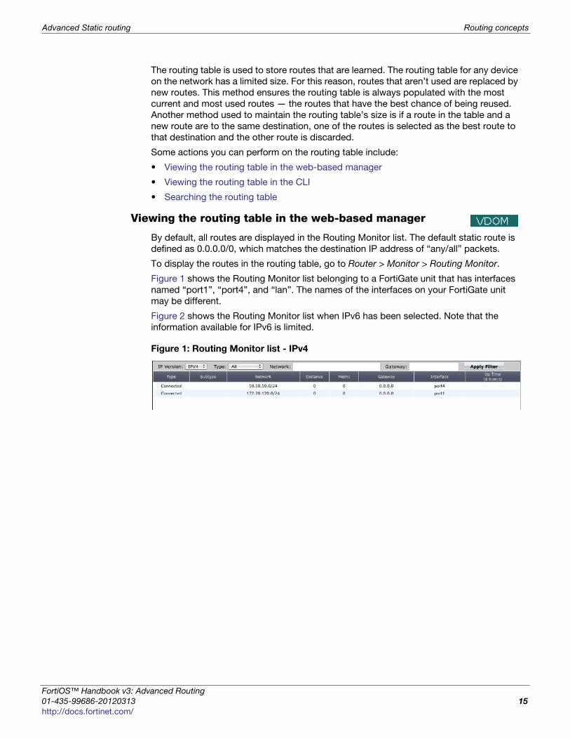
Viewing the routing table in the web-based manager
By default, all routes are displayed in the Routing Monitor list. The default static route is
defined as 0.0.0.0/0, which matches the destination IP address of “any/all” packets.
To display the routes in the routing table, go to Router > Monitor > Routing Monitor.
Figure 1 shows the Routing Monitor list belonging to a FortiGate unit that has interfaces
named “port1”, “port4”, and “lan”. The names of the interfaces on your FortiGate unit
may be different.
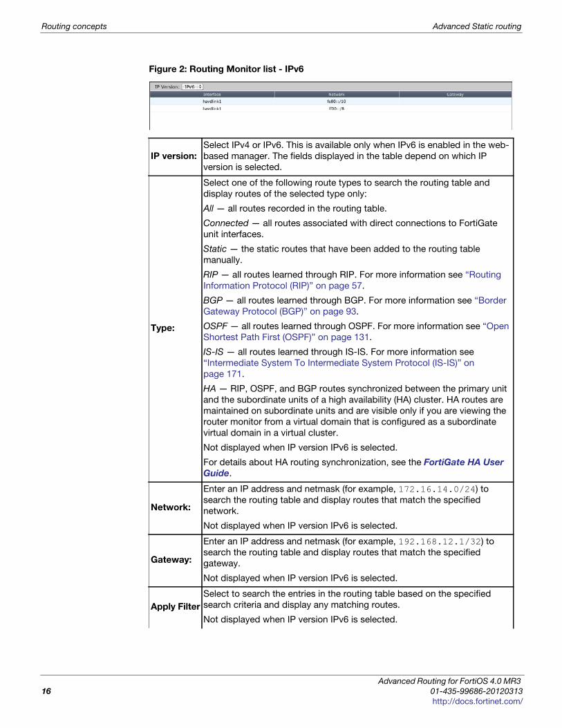
Figure 2 shows the Routing Monitor list when IPv6 has been selected. Note that the
information available for IPv6 is limited.
Figure 1: Routing Monitor list - IPv4
ortiOS™ Handbook v3: Advanced Routing
1-435-99686-20120313 15
ttp://docs.fortinet.com/
Routing concepts Advanced Static routing
Figure 2: Routing Monitor list - IPv6
IP version:
Select IPv4 or IPv6. This is available only when IPv6 is enabled in the web-
based manager. The fields displayed in the table depend on which IP
version is selected.
Type:
Select one of the following route types to search the routing table and
display routes of the selected type only:
All — all routes recorded in the routing table.
Connected — all routes associated with direct connections to FortiGate
unit interfaces.
Static — the static routes that have been added to the routing table
manually.
RIP — all routes learned through RIP. For more information see “Routing
Information Protocol (RIP)” on page 57.
BGP — all routes learned through BGP. For more information see “Border
Gateway Protocol (BGP)” on page 93.
OSPF — all routes learned through OSPF. For more information see “Open
Shortest Path First (OSPF)” on page 131.
IS-IS — all routes learned through IS-IS. For more information see
“Intermediate System To Intermediate System Protocol (IS-IS)” on
page 171.
HA — RIP, OSPF, and BGP routes synchronized between the primary unit
and the subordinate units of a high availability (HA) cluster. HA routes are
maintained on subordinate units and are visible only if you are viewing the
router monitor from a virtual domain that is configured as a subordinate
virtual domain in a virtual cluster.
Not displayed when IP version IPv6 is selected.
For details about HA routing synchronization, see the FortiGate HA User
Guide.
Network:
Enter an IP address and netmask (for example, 172.16.14.0/24) to
search the routing table and display routes that match the specified
network.
Not displayed when IP version IPv6 is selected.
Gateway:
Enter an IP address and netmask (for example, 192.168.12.1/32) to
search the routing table and display routes that match the specified
gateway.
Not displayed when IP version IPv6 is selected.
Apply Filter
Select to search the entries in the routing table based on the specified
search criteria and display any matching routes.
Not displayed when IP version IPv6 is selected.
Advanced Routing for FortiOS 4.0 MR3
16 01-435-99686-20120313
http://docs.fortinet.com/
Advanced Static routing Routing concepts
F
0
h
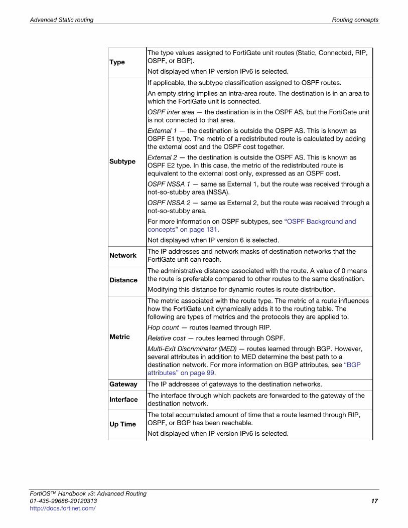
Type
The type values assigned to FortiGate unit routes (Static, Connected, RIP,
OSPF, or BGP).
Not displayed when IP version IPv6 is selected.
Subtype
If applicable, the subtype classification assigned to OSPF routes.
An empty string implies an intra-area route. The destination is in an area to
which the FortiGate unit is connected.
OSPF inter area — the destination is in the OSPF AS, but the FortiGate unit
is not connected to that area.
External 1 — the destination is outside the OSPF AS. This is known as
OSPF E1 type. The metric of a redistributed route is calculated by adding
the external cost and the OSPF cost together.
External 2 — the destination is outside the OSPF AS. This is known as
OSPF E2 type. In this case, the metric of the redistributed route is
equivalent to the external cost only, expressed as an OSPF cost.
OSPF NSSA 1 — same as External 1, but the route was received through a
not-so-stubby area (NSSA).
OSPF NSSA 2 — same as External 2, but the route was received through a
not-so-stubby area.
For more information on OSPF subtypes, see “OSPF Background and
concepts” on page 131.
Not displayed when IP version 6 is selected.
NetworkThe IP addresses and network masks of destination networks that the
FortiGate unit can reach.
Distance
The administrative distance associated with the route. A value of 0 means
the route is preferable compared to other routes to the same destination.
Modifying this distance for dynamic routes is route distribution.
Metric
The metric associated with the route type. The metric of a route influences
how the FortiGate unit dynamically adds it to the routing table. The
following are types of metrics and the protocols they are applied to.
Hop count — routes learned through RIP.
Relative cost — routes learned through OSPF.
Multi-Exit Discriminator (MED) — routes learned through BGP. However,
several attributes in addition to MED determine the best path to a
destination network. For more information on BGP attributes, see “BGP
attributes” on page 99.
Gateway The IP addresses of gateways to the destination networks.
InterfaceThe interface through which packets are forwarded to the gateway of the
destination network.
Up Time
The total accumulated amount of time that a route learned through RIP,
OSPF, or BGP has been reachable.
Not displayed when IP version IPv6 is selected.
ortiOS™ Handbook v3: Advanced Routing
1-435-99686-20120313 17
ttp://docs.fortinet.com/
Routing concepts Advanced Static routing
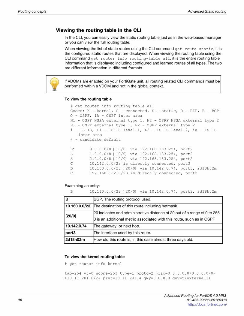
Viewing the routing table in the CLIIn the CLI, you can easily view the static routing table just as in the web-based manager
or you can view the full routing table.
When viewing the list of static routes using the CLI command get route static, it is
the configured static routes that are displayed. When viewing the routing table using the
CLI command get router info routing-table all, it is the entire routing table
information that is displayed including configured and learned routes of all types. The two
are different information in different formats.
To view the routing table
# get router info routing-table allCodes: K - kernel, C - connected, S - static, R - RIP, B - BGPO - OSPF, IA - OSPF inter areaN1 - OSPF NSSA external type 1, N2 - OSPF NSSA external type 2E1 - OSPF external type 1, E2 - OSPF external type 2i - IS-IS, L1 - IS-IS level-1, L2 - IS-IS level-2, ia - IS-IS
inter area* - candidate default
S* 0.0.0.0/0 [10/0] via 192.168.183.254, port2S 1.0.0.0/8 [10/0] via 192.168.183.254, port2S 2.0.0.0/8 [10/0] via 192.168.183.254, port2C 10.142.0.0/23 is directly connected, port3B 10.160.0.0/23 [20/0] via 10.142.0.74, port3, 2d18h02mC 192.168.182.0/23 is directly connected, port2
Examining an entry:
B 10.160.0.0/23 [20/0] via 10.142.0.74, port3, 2d18h02m
To view the kernel routing table
# get router info kernel
tab=254 vf=0 scope=253 type=1 proto=2 prio=0 0.0.0.0/0.0.0.0/0->10.11.201.0/24 pref=10.11.201.4 gwy=0.0.0.0 dev=5(external1)
If VDOMs are enabled on your FortiGate unit, all routing related CLI commands must be
performed within a VDOM and not in the global context.
B BGP. The routing protocol used.
10.160.0.0/23 The destination of this route including netmask.
[20/0]20 indicates and administrative distance of 20 out of a range of 0 to 255.
0 is an additional metric associated with this route, such as in OSPF
10.142.0.74 The gateway, or next hop.
port3 The interface used by this route.
2d18h02m How old this route is, in this case almost three days old.
Advanced Routing for FortiOS 4.0 MR3
18 01-435-99686-20120313
http://docs.fortinet.com/
Advanced Static routing Routing concepts
F
0
h
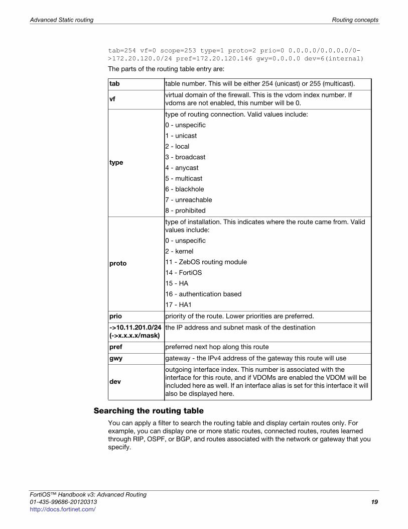
tab=254 vf=0 scope=253 type=1 proto=2 prio=0 0.0.0.0/0.0.0.0/0->172.20.120.0/24 pref=172.20.120.146 gwy=0.0.0.0 dev=6(internal)
The parts of the routing table entry are:
Searching the routing tableYou can apply a filter to search the routing table and display certain routes only. For
example, you can display one or more static routes, connected routes, routes learned
through RIP, OSPF, or BGP, and routes associated with the network or gateway that you
specify.
tab table number. This will be either 254 (unicast) or 255 (multicast).
vfvirtual domain of the firewall. This is the vdom index number. If
vdoms are not enabled, this number will be 0.
type
type of routing connection. Valid values include:
0 - unspecific
1 - unicast
2 - local
3 - broadcast
4 - anycast
5 - multicast
6 - blackhole
7 - unreachable
8 - prohibited
proto
type of installation. This indicates where the route came from. Valid
values include:
0 - unspecific
2 - kernel
11 - ZebOS routing module
14 - FortiOS
15 - HA
16 - authentication based
17 - HA1
prio priority of the route. Lower priorities are preferred.
->10.11.201.0/24
(->x.x.x.x/mask)
the IP address and subnet mask of the destination
pref preferred next hop along this route
gwy gateway - the IPv4 address of the gateway this route will use
dev
outgoing interface index. This number is associated with the
interface for this route, and if VDOMs are enabled the VDOM will be
included here as well. If an interface alias is set for this interface it will
also be displayed here.
ortiOS™ Handbook v3: Advanced Routing
1-435-99686-20120313 19
ttp://docs.fortinet.com/
Routing concepts Advanced Static routing
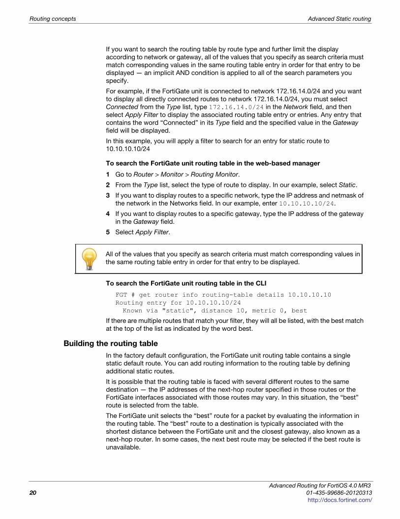
If you want to search the routing table by route type and further limit the display
according to network or gateway, all of the values that you specify as search criteria must
match corresponding values in the same routing table entry in order for that entry to be
displayed — an implicit AND condition is applied to all of the search parameters you
specify.
For example, if the FortiGate unit is connected to network 172.16.14.0/24 and you want
to display all directly connected routes to network 172.16.14.0/24, you must select
Connected from the Type list, type 172.16.14.0/24 in the Network field, and then
select Apply Filter to display the associated routing table entry or entries. Any entry that
contains the word “Connected” in its Type field and the specified value in the Gateway
field will be displayed.
In this example, you will apply a filter to search for an entry for static route to
10.10.10.10/24
To search the FortiGate unit routing table in the web-based manager
1 Go to Router > Monitor > Routing Monitor.
2 From the Type list, select the type of route to display. In our example, select Static.
3 If you want to display routes to a specific network, type the IP address and netmask of
the network in the Networks field. In our example, enter 10.10.10.10/24.
4 If you want to display routes to a specific gateway, type the IP address of the gateway
in the Gateway field.
5 Select Apply Filter.
To search the FortiGate unit routing table in the CLI
FGT # get router info routing-table details 10.10.10.10Routing entry for 10.10.10.10/24Known via "static", distance 10, metric 0, best
If there are multiple routes that match your filter, they will all be listed, with the best match
at the top of the list as indicated by the word best.
Building the routing table
In the factory default configuration, the FortiGate unit routing table contains a single
static default route. You can add routing information to the routing table by defining
additional static routes.
It is possible that the routing table is faced with several different routes to the same
destination — the IP addresses of the next-hop router specified in those routes or the
FortiGate interfaces associated with those routes may vary. In this situation, the “best”
route is selected from the table.
The FortiGate unit selects the “best” route for a packet by evaluating the information in
the routing table. The “best” route to a destination is typically associated with the
shortest distance between the FortiGate unit and the closest gateway, also known as a
next-hop router. In some cases, the next best route may be selected if the best route is
unavailable.
All of the values that you specify as search criteria must match corresponding values in
the same routing table entry in order for that entry to be displayed.
Advanced Routing for FortiOS 4.0 MR3
20 01-435-99686-20120313
http://docs.fortinet.com/
Advanced Static routing Routing concepts
F
0
h
The FortiGate unit installs the best available routes in the unit’s forwarding table, which is
a subset of the unit’s routing table. Packets are forwarded according to the information in
the forwarding table.
Static routing security
Securing the information on your company network is a top priority for network
administrators. Security is also required as the routing protocols used are internationally
known standards that typically provide little or no inherent security by themselves.
The two reasons for securing your network are the sensitive and proprietary information
on your network, and also your external bandwidth. Hackers not only can steal your
information, but they can also steal your bandwidth. Routing is a good low level way to
secure your network, even before UTM features are applied.
Routing provides security to your network in a number of ways including obscuring
internal network addresses with NAT and blackhole routing, using RPF to validate traffic
sources, and maintaining an access control list (ACL) to limit access to the network.
This section includes:
• Network Address Translation (NAT)
• Access Control List (ACL)
• Blackhole Route
• Reverse path lookup
Network Address Translation (NAT)Network address translation (NAT) is a method of changing the address traffic appears to
originate from. This practice is used to hide the IP address on company’s internal
networks, and helps prevent malicious attacks that use those specific addresses.
This is accomplished by the router connected to that local network changing all the IP
addresses to its externally connected IP address before sending the traffic out to the
other networks, such as the Internet. Incoming traffic uses the established sessions to
determine which traffic goes to which internal IP address. This also has the benefit of
requiring only the router to be very secure against external attacks, instead of the whole
internal network as would be the case without NAT. Securing one computer is much
cheaper and easier to maintain.
Configuring NAT on your FortiGate unit includes the following steps.
1 Configure your internal network. For example use the 10.11.101.0 subnet.
2 Connect your internal subnet to an interface on your FortiGate unit. For example use
port1.
3 Connect your external connection, for example an ISP gateway of 172.20.120.2, to
another interface on your Fortigate unit, for example port2.
4 Configure security policies to allow traffic between port1 and port2 on your FortiGate
unit, ensuring that the NAT feature is enabled.
The above steps show that traffic from your internal network will originate on the
10.11.101.0 subnet and pass on to the 172.20.120.0 network. The FortiGate unit moves
the traffic to the proper subnet. In doing that, the traffic appears to originate from the
FortiGate unit interface on that subnet — it does not appear to originate from where it
actually came from.
ortiOS™ Handbook v3: Advanced Routing
1-435-99686-20120313 21
ttp://docs.fortinet.com/
Routing concepts Advanced Static routing
NAT “hides” the internal network from the external network. This provides security
through obscurity. If a hacker tries to directly access your network, they will find the
Fortigate unit, but will not know about your internal network. The hacker would have to
get past the security-hardened FortiGate unit to gain access to your internal network.
NAT will not prevent hacking attempts that piggy back on valid connections between the
internal network and the outside world. However other UTM security measures can deal
with these attempts.
Another security aspect of NAT is that many programs and services have problems with
NAT. Consider if someone on the Internet tries to initiate a chat with someone on the
internal network. The outsider only can access the FortiGate unit’s external interface
unless the security policy allows the traffic through to the internal network. If allowed in,
the proper internal user would respond to the chat. However if its not allowed, the
request to chat will be refused or time-out. This is accomplished in the security policy by
allowing or denying different protocols.
Access Control List (ACL)An access control list (ACL) is a table of addresses that have permission to send and
receive data over a router’s interface or interfaces. The router maintains an ACL, and
when traffic comes in on a particular interface it is buffered, while the router looks up in
the ACL if that traffic is allowed over that port or not. If it is allowed on that incoming
interface, then the next step is to check the ACL for the destination interface. If the traffic
passes that check as well the buffered traffic is delivered to its accentuation. If either of
those steps fail the ACL check, the traffic is dropped and an error message may be sent
to the sender. The ACL ensures that traffic follows expected paths, and any unexpected
traffic is not delivered. This stops many network attacks. However, to be effective the
ACL must be kept up to date —when employees or computers are removed from the
internal network their IP addresses must also be removed from the ACL. For more
information on the ACL, see the router chapter of the FortiGate CLI Reference.
Blackhole RouteA blackhole route is a route that drops all traffic sent to it. It is very much like /dev/null in
Linux programming.
Blackhole routes are used to dispose of packets instead of responding to suspicious
inquiries. This provides added security since the originator will not discover any
information from the target network.
Blackhole routes can also limit traffic on a subnet. If some subnet addresses are not in
use, traffic to those addresses (traffic which may be valid or malicious) can be directed to
a blackhole for added security and to reduce traffic on the subnet.
The loopback interface, a virtual interface that does not forward traffic, was added to
enable easier configuration of blackhole routing. Similar to a normal interface, this
loopback interface has fewer parameters to configure, and all traffic sent to it stops there.
Since it cannot have hardware connection or link status problems, it is always available,
making it useful for other dynamic routing roles. Once configured, you can use a
loopback interface in security policies, routing, and other places that refer to interfaces.
You configure this feature only from the CLI. For more information, see the system
chapter of the FortiGate CLI Reference.
Advanced Routing for FortiOS 4.0 MR3
22 01-435-99686-20120313
http://docs.fortinet.com/
Advanced Static routing Routing concepts
F
0
h
Reverse path lookupWhenever a packet arrives at one of the FortiGate unit’s interfaces, the unit determines
whether the packet was received on a legitimate interface by doing a reverse lookup
using the source IP address in the packet header. This is also called anti-spoofing. If the
FortiGate unit cannot communicate with the computer at the source IP address through
the interface on which the packet was received, the FortiGate unit drops the packet as it
is likely a hacking attempt.
If the destination address can be matched to a local address (and the local configuration
permits delivery), the FortiGate unit delivers the packet to the local network. If the packet
is destined for another network, the Fortigate unit forwards the packet to a next-hop
router according to a policy route and the information stored in the FortiGate forwarding
table.
Multipath routing and determining the best route
Multipath routing occurs when more than one entry to the same destination is present in
the routing table. When multipath routing happens, the FortiGate unit may have several
possible destinations for an incoming packet, forcing the FortiGate unit to decide which
next-hop is the best one.
It should be noted that some IP addresses will be rejected by routing protocols. These
are called Martian addresses. They are typically IP addresses that are invalid and not
routable because they have been assigned an address by a misconfigured system, or are
spoofed addresses.
Two methods to manually resolve multiple routes to the same destination are to lower the
administrative distance of one route or to set the priority of both routes. For the FortiGate
unit to select a primary (preferred) route, manually lower the administrative distance
associated with one of the possible routes. Setting the priority on the routes is a
FortiGate unit feature and may not be supported by non-Fortinet routers.
Administrative distance is based on the expected reliability of a given route. It is
determined through a combination of the number of hops from the source and the
protocol used. A hop is when traffic moves from one router to the next. More hops from
the source means more possible points of failure. The administrative distance can be
from 1 to 255, with lower numbers being preferred. A distance of 255 is seen as infinite
and will not be installed in the routing table.
Here is an example to illustrate how administration distance works — if there are two
possible routes traffic can take between two destinations with administration distances of
5 (always up) and 31 (sometimes not available), the traffic will use the route with an
administrative distance of 5. If for some reasons the preferred route (admin distance of 5)
is not available, the other route will be used as a backup.
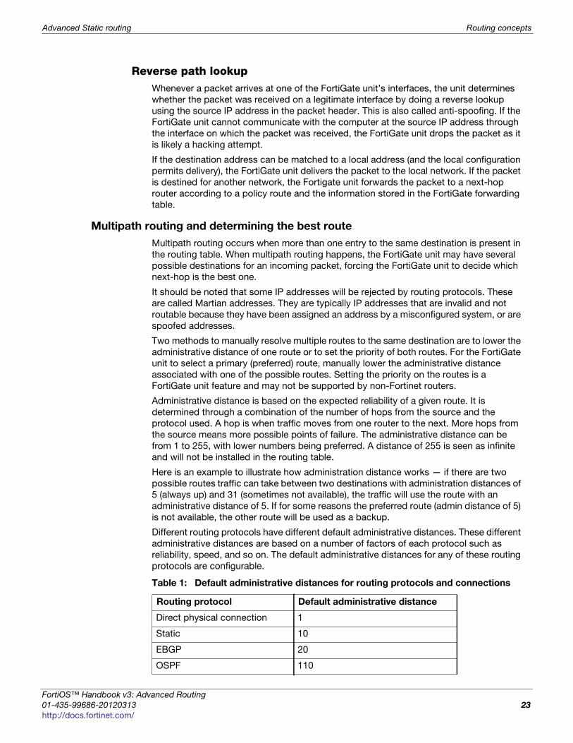
Different routing protocols have different default administrative distances. These different
administrative distances are based on a number of factors of each protocol such as
reliability, speed, and so on. The default administrative distances for any of these routing
protocols are configurable.
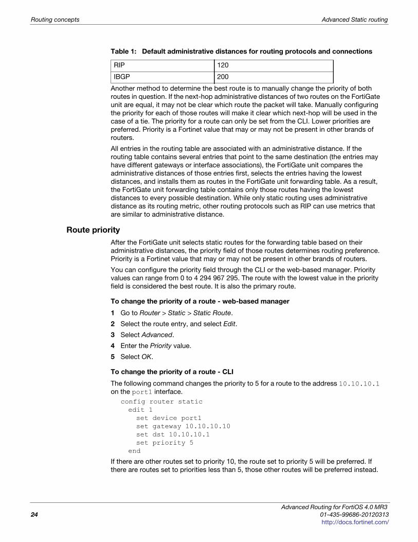
Table 1: Default administrative distances for routing protocols and connections
Routing protocol Default administrative distance
Direct physical connection 1
Static 10
EBGP 20
OSPF 110
ortiOS™ Handbook v3: Advanced Routing
1-435-99686-20120313 23
ttp://docs.fortinet.com/
Routing concepts Advanced Static routing
Another method to determine the best route is to manually change the priority of both
routes in question. If the next-hop administrative distances of two routes on the FortiGate
unit are equal, it may not be clear which route the packet will take. Manually configuring
the priority for each of those routes will make it clear which next-hop will be used in the
case of a tie. The priority for a route can only be set from the CLI. Lower priorities are
preferred. Priority is a Fortinet value that may or may not be present in other brands of
routers.
All entries in the routing table are associated with an administrative distance. If the
routing table contains several entries that point to the same destination (the entries may
have different gateways or interface associations), the FortiGate unit compares the
administrative distances of those entries first, selects the entries having the lowest
distances, and installs them as routes in the FortiGate unit forwarding table. As a result,
the FortiGate unit forwarding table contains only those routes having the lowest
distances to every possible destination. While only static routing uses administrative
distance as its routing metric, other routing protocols such as RIP can use metrics that
are similar to administrative distance.
Route priority
After the FortiGate unit selects static routes for the forwarding table based on their
administrative distances, the priority field of those routes determines routing preference.
Priority is a Fortinet value that may or may not be present in other brands of routers.
You can configure the priority field through the CLI or the web-based manager. Priority
values can range from 0 to 4 294 967 295. The route with the lowest value in the priority
field is considered the best route. It is also the primary route.
To change the priority of a route - web-based manager
1 Go to Router > Static > Static Route.
2 Select the route entry, and select Edit.
3 Select Advanced.
4 Enter the Priority value.
5 Select OK.
To change the priority of a route - CLI
The following command changes the priority to 5 for a route to the address 10.10.10.1
on the port1 interface.
config router staticedit 1set device port1set gateway 10.10.10.10set dst 10.10.10.1set priority 5
end
If there are other routes set to priority 10, the route set to priority 5 will be preferred. If
there are routes set to priorities less than 5, those other routes will be preferred instead.
RIP 120
IBGP 200
Table 1: Default administrative distances for routing protocols and connections
Advanced Routing for FortiOS 4.0 MR3
24 01-435-99686-20120313
http://docs.fortinet.com/
Advanced Static routing Routing concepts
F
0
h
In summary, because you can use the CLI to specify which sequence numbers or priority
field settings to use when defining static routes, you can prioritize routes to the same
destination according to their priority field settings. For a static route to be the preferred
route, you must create the route using the config router static CLI command and
specify a low priority for the route. If two routes have the same administrative distance
and the same priority, then they are equal cost multipath (ECMP) routes.
Since this means there is more than one route to the same destination, it can be
confusing which route or routes to install and use. However, if you have enabled load
balancing with ECMP routes, then different sessions will resolve this problem by using
different routes to the same address.
Troubleshooting static routing
When there are problems with your network that you believe to be static routing related,
there are a few basic tools available to locate the problem.
These tools include:
• Ping
• Traceroute
• Examine routing table contents
PingBeyond the basic connectivity information, ping can tell you the amount of packet loss (if
any), how long it takes the packet to make the round trip, and the variation in that time
from packet to packet.
If there is no packet loss detected, your basic network connectivity is OK.
If there is some packet loss detected, you should investigate:
• possible ECMP, split horizon, network loops
• cabling to ensure no loose connections
If there is total packet loss, you should investigate:
• hardware - ensure cabling is correct, and all equipment between the two locations is
accounted for
• addresses and routes - ensure all IP addresses and routing information along the
route is configured as expected
• firewalls - ensure all firewalls are set to allow PING to pass through
To ping from a Windows PC
1 Go to a DOS prompt. Typically you go to Start > Run, enter cmd and select OK.
2 Enter ping 10.11.101.100 to ping the default internal interface of the FortiGate
unit with four packets.
To ping from a Linux PC
1 Go to a command line prompt.
2 Enter “/bin/etc/ping 10.11.101.101”.
ortiOS™ Handbook v3: Advanced Routing
1-435-99686-20120313 25
ttp://docs.fortinet.com/
Routing concepts Advanced Static routing
TracerouteWhere ping will only tell you if it reached its destination and came back successfully,
traceroute will show each step of its journey to its destination and how long each step
takes. If ping finds an outage between two points, traceroute can be used to locate
exactly where the problem is.
To use traceroute on an MS Windows PC
1 Go to a DOS prompt. Typically you go to Start > Run, enter “cmd” and select OK.
2 Enter “tracert fortinet.com” to trace the route from the PC to the Fortinet
website.
To perform a traceroute on a Linux PC
1 Go to a command line prompt.
2 Enter “/bin/etc/traceroute fortinet.com”.
The Linux traceroute output is very similar to the MS Windows traceroute output.
Examine routing table contentsThe first place to look for information is the routing table.
The routing table is where all the currently used routes are stored for both static and
dynamic protocols. If a route is in the routing table, it saves the time and resources of a
lookup. If a route isn’t used for a while and a new route needs to be added, the oldest
least used route is bumped if the routing table is full. This ensures the most recently used
routes stay in the table. Note that if your FortiGate unit is in Transparent mode, you are
unable to perform this step.
If the FortiGate is running in NAT mode, verify that all desired routes are in the routing
table: local subnets, default routes, specific static routes, and dynamic routing protocols.
To check the routing table in the web-based manager, use the Routing Monitor — go to
Router > Monitor > Routing Monitor. In the CLI, use the command get router info routing-table all.
To examine the firewall session list in the web-based manager
1 Go to System > Dashboard > Status > Top Sessions.
2 Select Detach, and then Details.
3 Expand the session window to full screen to display the information.
4 Change filters, view associated security policy, column ordering, and so on to analyze
the sessions in the table.
5 Select the delete icon to terminate the session.
Advanced Routing for FortiOS 4.0 MR3
26 01-435-99686-20120313
http://docs.fortinet.com/
Advanced Static routing ECMP route failover and load balancing
F
0
h
ECMP route failover and load balancing
Equal Cost Multi-Path (ECMP) load balancing and failover are methods that extend basic
static routing. They allow you to use your network bandwidth more effectively and with
less down time than if you used basic static routing alone.
The concepts in this section include:
• Equal-Cost Multi-Path (ECMP)
• Priority and ECMP
• Configuring interface status detection for gateway load balancing
• Configuring spillover or usage-based ECMP
• Configuring weighted static route load balancing
Equal-Cost Multi-Path (ECMP)
FortiOS uses equal-cost multi-path (ECMP) to distribute traffic to the same destination
such as the Internet or another network. Using ECMP you can add multiple routes to the
destination and give each of those routes the same distance and priority.
Using ECMP, if more than one ECMP route is available you can configure how the
FortiGate unit selects the route to be used for a communication session. If only one
ECMP route is available (for example, because an interface cannot process traffic
because interface status detection does not receive a reply from the configured server)
then all traffic uses this route.
Previous versions of FortiOS provided source IP-based load balancing for ECMP routes,
but now FortiOS includes three configuration options for ECMP route failover and load
balancing:
If multiple routes to the same destination have the same priority but different distances,
the route with the lowest distance is used. If multiple routes to the same destination
have the same distance but different priorities, the route with the lowest priority is used.
Distance takes precedence over priority. If multiple routes to the same destination have
different distances and different priorities, the route with the lowest distance is always
used even if it has the highest priority.
Source based
(also called source IP
based)
The FortiGate unit load balances sessions among ECMP
routes based on the source IP address of the sessions to be
load balanced. This is the default load balancing method. No
configuration changes are required to support source IP load
balancing.
ortiOS™ Handbook v3: Advanced Routing
1-435-99686-20120313 27
ttp://docs.fortinet.com/
ECMP route failover and load balancing Advanced Static routing
You can configure only one of these ECMP route failover and load balancing methods in a
single VDOM. If your FortiGate unit is configured for multiple VDOM operation, each
VDOM can have its own ECMP route failover and load balancing configuration.
To configure the ECMP load balancing method from the web-based manager
1 Go to Router > Static > Settings.
2 Set ECMP Load Balance Method to Source IP based, Weighted Load Balance, or
Spillover.
To configure the ECMP load balancing method from the CLI
For example, to set the load balancing method to usage-based, enter the following:
config system settingsset v4-ecmp-mode usage-based
end
ECMP routing of simultaneous sessions to the same destination IP addressWhen the FortiGate unit selects an ECMP route for a session, a route cache is created
that matches the route with the destination IP address of the session. All new sessions to
the same destination IP address use the same route until the route is flushed from the
cache. Routes are flushed from the cache after a period of time when no new sessions to
the destination IP address are received.
The route cache improves FortiGate unit routing performance by reducing how often the
FortiGate unit looks up routes in the routing table.
If the FortiGate unit receives a large number of sessions with the same destination IP
address, because all of these sessions will be processed by the same route, it may
appear that sessions are not distributed according to the ECMP route failover and load
balancing configuration.
Priority and ECMP
Priority is used in determining the structure of ECMP load balancing. For an overview of
priority, see “Route priority” on page 24.
Weighted Load
Balance (also called
weight-based)
The FortiGate unit load balances sessions among ECMP
routes based on weights added to ECMP routes. More traffic
is directed to routes with higher weights. After selecting
weight-based you must add weights to static routes.
Spillover (also called
usage-based)
The FortiGate unit distributes sessions among ECMP routes
based on how busy the FortiGate interfaces added to the
routes are.
After selecting spill-over you add route Spillover Thresholds to
interfaces added to ECMP routes. The FortiGate unit sends all
ECMP-routed sessions to the lowest numbered interface until
the bandwidth being processed by this interface reaches its
spillover threshold. The FortiGate unit then spills additional
sessions over to the next lowest numbered interface.
The Spillover Thresholds range is 0-2097000 KBps.
Advanced Routing for FortiOS 4.0 MR3
28 01-435-99686-20120313
http://docs.fortinet.com/
Advanced Static routing ECMP route failover and load balancing
F
0
h
Because you can use the CLI to specify which sequence numbers or priority field settings
to use when defining static routes, you can prioritize routes to the same destination
according to their priority field settings. For a static route to be the preferred route, you
must create the route using the config router static CLI command and specify a
low priority for the route. If two routes have the same administrative distance and the
same priority, then they are equal cost multipath (ECMP) routes.
Since this means there is more than one route to the same destination, it can be
confusing which route or routes to install and use. However, if you have enabled load
balancing with ECMP routes, then different sessions will resolve this problem by using
different routes to the same address.
Configuring interface status detection for gateway load balancing
Interface status detection is used for ECMP route failover and load balancing. Interface
status detection consists of the unit confirming that packets sent from an interface result
in a response from a server. You can use up to three different protocols to confirm that an
interface can connect to the server. Usually the server is the next-hop router that leads to
an external network or the Internet. Interface status detection sends a packet using the
configured protocols. If a response is received from the server, the unit assumes the
interface can connect to the network. If a response is not received, the unit assumes that
the interface cannot connect to the network.
Since it is possible that a response may not be received, even if the server and the
network are operating normally, the dead gateway detection configuration controls the
time interval between testing the connection to the server and the number of times the
test can fail before the unit assumes that the interface cannot connect to the server.
To configure gateway failover detection for an interface
1 Go to Router > Static > Settings.
2 Under Dead Gateway Detection, select Create New.
As long as the unit receives responses for at least one of the protocols that you select,
the unit assumes the server is operating and can forward packets. Responding to more
than one protocol does not enhance the status of the server or interface.
ortiOS™ Handbook v3: Advanced Routing
1-435-99686-20120313 29
ttp://docs.fortinet.com/
ECMP route failover and load balancing Advanced Static routing
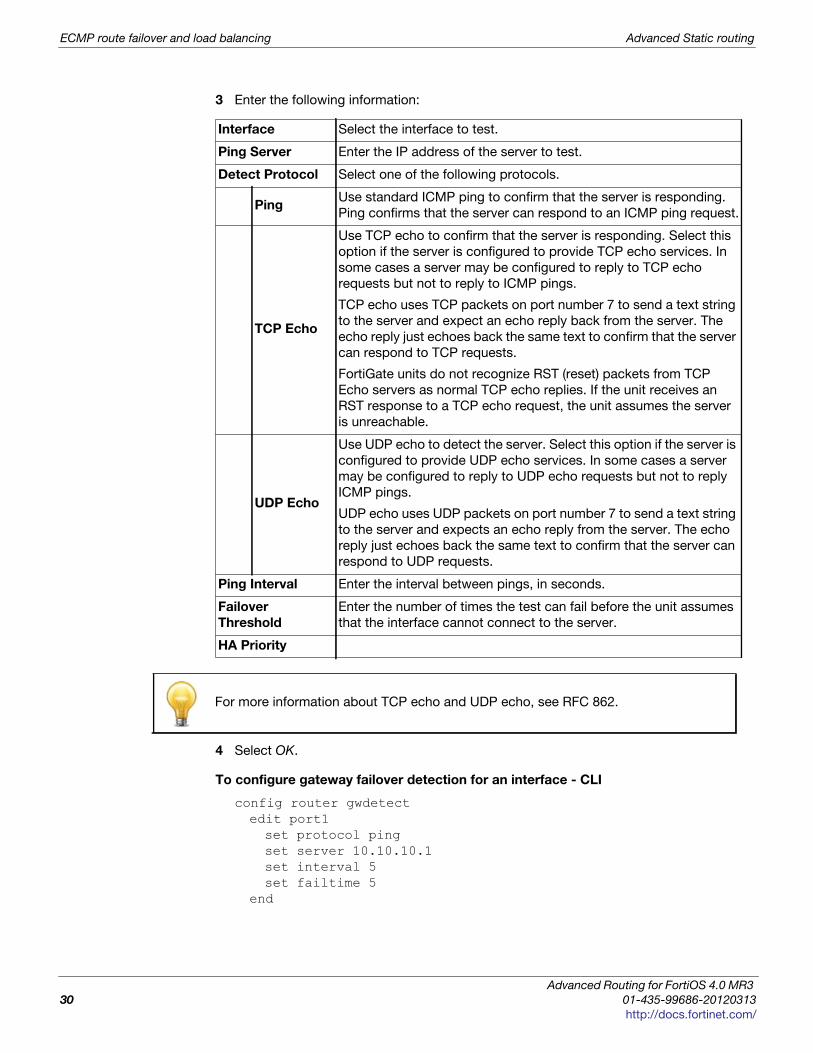
3 Enter the following information:
4 Select OK.
To configure gateway failover detection for an interface - CLI
config router gwdetectedit port1set protocol pingset server 10.10.10.1set interval 5set failtime 5
end
Interface Select the interface to test.
Ping Server Enter the IP address of the server to test.
Detect Protocol Select one of the following protocols.
PingUse standard ICMP ping to confirm that the server is responding.
Ping confirms that the server can respond to an ICMP ping request.
TCP Echo
Use TCP echo to confirm that the server is responding. Select this
option if the server is configured to provide TCP echo services. In
some cases a server may be configured to reply to TCP echo
requests but not to reply to ICMP pings.
TCP echo uses TCP packets on port number 7 to send a text string
to the server and expect an echo reply back from the server. The
echo reply just echoes back the same text to confirm that the server
can respond to TCP requests.
FortiGate units do not recognize RST (reset) packets from TCP
Echo servers as normal TCP echo replies. If the unit receives an
RST response to a TCP echo request, the unit assumes the server
is unreachable.
UDP Echo
Use UDP echo to detect the server. Select this option if the server is
configured to provide UDP echo services. In some cases a server
may be configured to reply to UDP echo requests but not to reply
ICMP pings.
UDP echo uses UDP packets on port number 7 to send a text string
to the server and expects an echo reply from the server. The echo
reply just echoes back the same text to confirm that the server can
respond to UDP requests.
Ping Interval Enter the interval between pings, in seconds.
Failover
Threshold
Enter the number of times the test can fail before the unit assumes
that the interface cannot connect to the server.
HA Priority
For more information about TCP echo and UDP echo, see RFC 862.
Advanced Routing for FortiOS 4.0 MR3
30 01-435-99686-20120313
http://docs.fortinet.com/
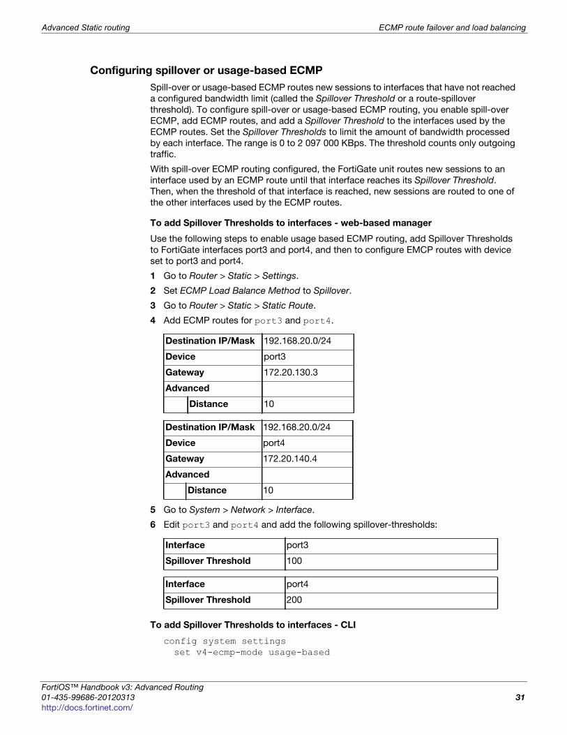
Advanced Static routing ECMP route failover and load balancing
F
0
h
Configuring spillover or usage-based ECMP
Spill-over or usage-based ECMP routes new sessions to interfaces that have not reached
a configured bandwidth limit (called the Spillover Threshold or a route-spillover
threshold). To configure spill-over or usage-based ECMP routing, you enable spill-over
ECMP, add ECMP routes, and add a Spillover Threshold to the interfaces used by the
ECMP routes. Set the Spillover Thresholds to limit the amount of bandwidth processed
by each interface. The range is 0 to 2 097 000 KBps. The threshold counts only outgoing
traffic.
With spill-over ECMP routing configured, the FortiGate unit routes new sessions to an
interface used by an ECMP route until that interface reaches its Spillover Threshold.
Then, when the threshold of that interface is reached, new sessions are routed to one of
the other interfaces used by the ECMP routes.
To add Spillover Thresholds to interfaces - web-based manager
Use the following steps to enable usage based ECMP routing, add Spillover Thresholds
to FortiGate interfaces port3 and port4, and then to configure EMCP routes with device
set to port3 and port4.
1 Go to Router > Static > Settings.
2 Set ECMP Load Balance Method to Spillover.
3 Go to Router > Static > Static Route.
4 Add ECMP routes for port3 and port4.
5 Go to System > Network > Interface.
6 Edit port3 and port4 and add the following spillover-thresholds:
To add Spillover Thresholds to interfaces - CLI
config system settingsset v4-ecmp-mode usage-based
Destination IP/Mask 192.168.20.0/24
Device port3
Gateway 172.20.130.3
Advanced
Distance 10
Destination IP/Mask 192.168.20.0/24
Device port4
Gateway 172.20.140.4
Advanced
Distance 10
Interface port3
Spillover Threshold 100
Interface port4
Spillover Threshold 200
ortiOS™ Handbook v3: Advanced Routing
1-435-99686-20120313 31
ttp://docs.fortinet.com/
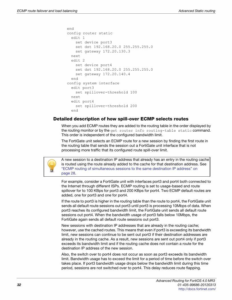
ECMP route failover and load balancing Advanced Static routing
endconfig router staticedit 1set device port3set dst 192.168.20.0 255.255.255.0set gateway 172.20.130.3
nextedit 2set device port4set dst 192.168.20.0 255.255.255.0set gateway 172.20.140.4
endconfig system interfaceedit port3set spillover-threshold 100
nextedit port4set spillover-threshold 200
end
Detailed description of how spill-over ECMP selects routesWhen you add ECMP routes they are added to the routing table in the order displayed by
the routing monitor or by the get router info routing-table static command.
This order is independent of the configured bandwidth limit.
The FortiGate unit selects an ECMP route for a new session by finding the first route in
the routing table that sends the session out a FortiGate unit interface that is not
processing more traffic that its configured route spill-over limit.
For example, consider a FortiGate unit with interfaces port3 and port4 both connected to
the Internet through different ISPs. ECMP routing is set to usage-based and route
spillover for to 100 KBps for port3 and 200 KBps for port4. Two ECMP default routes are
added, one for port3 and one for port4.
If the route to port3 is higher in the routing table than the route to port4, the FortiGate unit
sends all default route sessions out port3 until port3 is processing 10Mbps of data. When
port3 reaches its configured bandwidth limit, the FortiGate unit sends all default route
sessions out port4. When the bandwidth usage of port3 falls below 10Mbps, the
FortiGate again sends all default route sessions out port3.
New sessions with destination IP addresses that are already in the routing cache;
however, use the cached routes. This means that even if port3 is exceeding its bandwidth
limit, new sessions can continue to be sent out port3 if their destination addresses are
already in the routing cache. As a result, new sessions are sent out port4 only if port3
exceeds its bandwidth limit and if the routing cache does not contain a route for the
destination IP address of the new session.
Also, the switch over to port4 does not occur as soon as port3 exceeds its bandwidth
limit. Bandwidth usage has to exceed the limit for a period of time before the switch over
takes place. If port3 bandwidth usage drops below the bandwidth limit during this time
period, sessions are not switched over to port4. This delay reduces route flapping.
A new session to a destination IP address that already has an entry in the routing cache
is routed using the route already added to the cache for that destination address. See
“ECMP routing of simultaneous sessions to the same destination IP address” on
page 28.
Advanced Routing for FortiOS 4.0 MR3
32 01-435-99686-20120313
http://docs.fortinet.com/
Advanced Static routing ECMP route failover and load balancing
F
0
h
FortiGate usage-based ECMP routing is not actually load balancing, since routes are not
distributed evenly among FortiGate interfaces. Depending on traffic volumes, most traffic
would usually be processed by the first interface with only spillover traffic being
processed by other interfaces.
If you are configuring usage-based ECMP in most cases you should add spillover
thresholds to all of the interfaces with ECMP routes. The default spillover threshold is 0
which means no bandwidth limiting. If any interface has a spillover threshold of 0, no
sessions will be routed to interfaces lower in the list unless the interface goes down or is
disconnected. An interface can go down if Detect interface status for Gateway Load
Balancing does not receive a response from the configured server.
Determining if an interface has exceeded its Spillover ThresholdYou can use the diagnose netlink dstmac list CLI command to determine if an
interface is exceeding its Spillover Threshold. If the command displays over_bps=1 the
interface is exceeding its threshold. If over_bps=0 the interface has not exceeded its
threshold.
Configuring weighted static route load balancing
Configure weighted load balancing to control how the FortiGate unit distributes sessions
among ECMP routes by adding weights for each route. Add higher weights to routes that
you want to load balance more sessions to.
With the ECMP load balancing method set to weighted, the FortiGate unit distributes
sessions with different destination IPs by generating a random value to determine the
route to select. The probability of selecting one route over another is based on the weight
value of each route. Routes with higher weights are more likely to be selected.
Large numbers of sessions are evenly distributed among ECMP routes according to the
route weight values. If all weights are the same, sessions are distributed evenly. The
distribution of a small number of sessions; however, may not be even. For example, its
possible that if there are two ECMP routes with the same weight; two sessions to
different IP addresses could use the same route. On the other hand, 10,000 sessions with
different destination IPs should be load balanced evenly between two routes with equal
rates. The distribution could be 5000:5000 or 50001:4999. Also, 10 000 sessions with
different destination IP addresses should be load balanced as 3333:6667 if the weights
for the two routes are 100 and 200.
Weights only affect how routes are selected for sessions to new destination IP addresses.
New sessions to IP addresses already in the routing cache are routed using the route for
the session already in the cache. So in practice sessions will not always be distributed
according to the routing weight distribution.
To add weights to static routes from the web-based manager
1 Go to Router > Static > Settings.
2 Set ECMP Load Balance Method to Weighted Load Balance.
3 Go to Router > Static > Static Route.
ortiOS™ Handbook v3: Advanced Routing
1-435-99686-20120313 33
ttp://docs.fortinet.com/
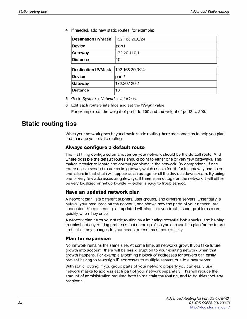
Static routing tips Advanced Static routing
4 If needed, add new static routes, for example:
5 Go to System > Network > Interface.
6 Edit each route’s interface and set the Weight value.
For example, set the weight of port1 to 100 and the weight of port2 to 200.
Static routing tips
When your network goes beyond basic static routing, here are some tips to help you plan
and manage your static routing.
Always configure a default routeThe first thing configured on a router on your network should be the default route. And
where possible the default routes should point to either one or very few gateways. This
makes it easier to locate and correct problems in the network. By comparison, if one
router uses a second router as its gateway which uses a fourth for its gateway and so on,
one failure in that chain will appear as an outage for all the devices downstream. By using
one or very few addresses as gateways, if there is an outage on the network it will either
be very localized or network-wide — either is easy to troubleshoot.
Have an updated network planA network plan lists different subnets, user groups, and different servers. Essentially is
puts all your resources on the network, and shows how the parts of your network are
connected. Keeping your plan updated will also help you troubleshoot problems more
quickly when they arise.
A network plan helps your static routing by eliminating potential bottlenecks, and helping
troubleshoot any routing problems that come up. Also you can use it to plan for the future
and act on any changes to your needs or resources more quickly.
Plan for expansionNo network remains the same size. At some time, all networks grow. If you take future
growth into account, there will be less disruption to your existing network when that
growth happens. For example allocating a block of addresses for servers can easily
prevent having to re-assign IP addresses to multiple servers due to a new server.
With static routing, if you group parts of your network properly you can easily use
network masks to address each part of your network separately. This will reduce the
amount of administration required both to maintain the routing, and to troubleshoot any
problems.
Destination IP/Mask 192.168.20.0/24
Device port1
Gateway 172.20.110.1
Distance 10
Destination IP/Mask 192.168.20.0/24
Device port2
Gateway 172.20.120.2
Distance 10
Advanced Routing for FortiOS 4.0 MR3
34 01-435-99686-20120313
http://docs.fortinet.com/
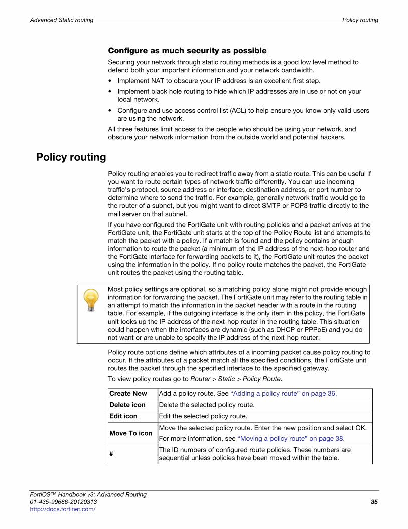
Advanced Static routing Policy routing
F
0
h
Configure as much security as possibleSecuring your network through static routing methods is a good low level method to
defend both your important information and your network bandwidth.
• Implement NAT to obscure your IP address is an excellent first step.
• Implement black hole routing to hide which IP addresses are in use or not on your
local network.
• Configure and use access control list (ACL) to help ensure you know only valid users
are using the network.
All three features limit access to the people who should be using your network, and
obscure your network information from the outside world and potential hackers.
Policy routing
Policy routing enables you to redirect traffic away from a static route. This can be useful if
you want to route certain types of network traffic differently. You can use incoming
traffic’s protocol, source address or interface, destination address, or port number to
determine where to send the traffic. For example, generally network traffic would go to
the router of a subnet, but you might want to direct SMTP or POP3 traffic directly to the
mail server on that subnet.
If you have configured the FortiGate unit with routing policies and a packet arrives at the
FortiGate unit, the FortiGate unit starts at the top of the Policy Route list and attempts to
match the packet with a policy. If a match is found and the policy contains enough
information to route the packet (a minimum of the IP address of the next-hop router and
the FortiGate interface for forwarding packets to it), the FortiGate unit routes the packet
using the information in the policy. If no policy route matches the packet, the FortiGate
unit routes the packet using the routing table.
Policy route options define which attributes of a incoming packet cause policy routing to
occur. If the attributes of a packet match all the specified conditions, the FortiGate unit
routes the packet through the specified interface to the specified gateway.
To view policy routes go to Router > Static > Policy Route.
Most policy settings are optional, so a matching policy alone might not provide enough
information for forwarding the packet. The FortiGate unit may refer to the routing table in
an attempt to match the information in the packet header with a route in the routing
table. For example, if the outgoing interface is the only item in the policy, the FortiGate
unit looks up the IP address of the next-hop router in the routing table. This situation
could happen when the interfaces are dynamic (such as DHCP or PPPoE) and you do
not want or are unable to specify the IP address of the next-hop router.
Create New Add a policy route. See “Adding a policy route” on page 36.
Delete icon Delete the selected policy route.
Edit icon Edit the selected policy route.
Move To iconMove the selected policy route. Enter the new position and select OK.
For more information, see “Moving a policy route” on page 38.
#The ID numbers of configured route policies. These numbers are
sequential unless policies have been moved within the table.
ortiOS™ Handbook v3: Advanced Routing
1-435-99686-20120313 35
ttp://docs.fortinet.com/
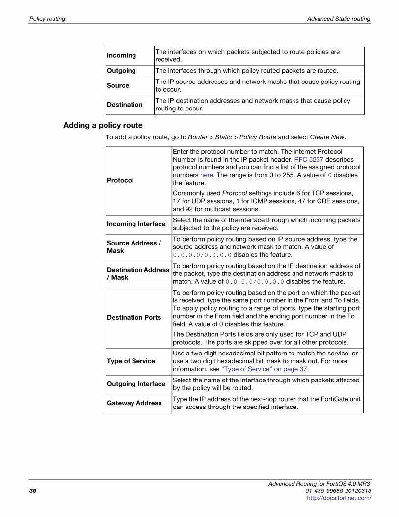
Policy routing Advanced Static routing
Adding a policy route
To add a policy route, go to Router > Static > Policy Route and select Create New.
IncomingThe interfaces on which packets subjected to route policies are
received.
Outgoing The interfaces through which policy routed packets are routed.
SourceThe IP source addresses and network masks that cause policy routing
to occur.
DestinationThe IP destination addresses and network masks that cause policy
routing to occur.
Protocol
Enter the protocol number to match. The Internet Protocol
Number is found in the IP packet header. RFC 5237 describes
protocol numbers and you can find a list of the assigned protocol
numbers here. The range is from 0 to 255. A value of 0 disables
the feature.
Commonly used Protocol settings include 6 for TCP sessions,
17 for UDP sessions, 1 for ICMP sessions, 47 for GRE sessions,
and 92 for multicast sessions.
Incoming InterfaceSelect the name of the interface through which incoming packets
subjected to the policy are received.
Source Address /
Mask
To perform policy routing based on IP source address, type the
source address and network mask to match. A value of
0.0.0.0/0.0.0.0 disables the feature.
Destination Address
/ Mask
To perform policy routing based on the IP destination address of
the packet, type the destination address and network mask to
match. A value of 0.0.0.0/0.0.0.0 disables the feature.
Destination Ports
To perform policy routing based on the port on which the packet
is received, type the same port number in the From and To fields.
To apply policy routing to a range of ports, type the starting port
number in the From field and the ending port number in the To
field. A value of 0 disables this feature.
The Destination Ports fields are only used for TCP and UDP
protocols. The ports are skipped over for all other protocols.
Type of Service
Use a two digit hexadecimal bit pattern to match the service, or
use a two digit hexadecimal bit mask to mask out. For more
information, see “Type of Service” on page 37.
Outgoing InterfaceSelect the name of the interface through which packets affected
by the policy will be routed.
Gateway AddressType the IP address of the next-hop router that the FortiGate unit
can access through the specified interface.
Advanced Routing for FortiOS 4.0 MR3
36 01-435-99686-20120313
http://docs.fortinet.com/
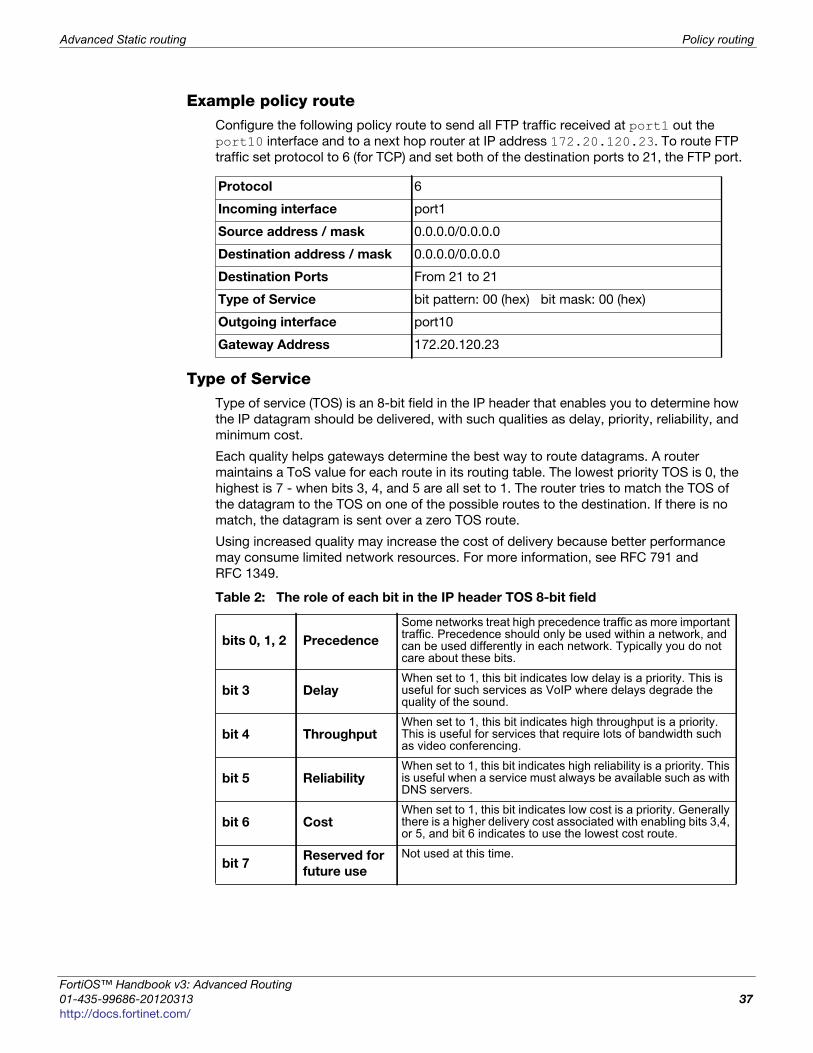
Advanced Static routing Policy routing
F
0
h
Example policy routeConfigure the following policy route to send all FTP traffic received at port1 out the
port10 interface and to a next hop router at IP address 172.20.120.23. To route FTP
traffic set protocol to 6 (for TCP) and set both of the destination ports to 21, the FTP port.
Type of ServiceType of service (TOS) is an 8-bit field in the IP header that enables you to determine how
the IP datagram should be delivered, with such qualities as delay, priority, reliability, and
minimum cost.
Each quality helps gateways determine the best way to route datagrams. A router
maintains a ToS value for each route in its routing table. The lowest priority TOS is 0, the
highest is 7 - when bits 3, 4, and 5 are all set to 1. The router tries to match the TOS of
the datagram to the TOS on one of the possible routes to the destination. If there is no
match, the datagram is sent over a zero TOS route.
Using increased quality may increase the cost of delivery because better performance
may consume limited network resources. For more information, see RFC 791 and
RFC 1349.
Protocol 6
Incoming interface port1
Source address / mask 0.0.0.0/0.0.0.0
Destination address / mask 0.0.0.0/0.0.0.0
Destination Ports From 21 to 21
Type of Service bit pattern: 00 (hex) bit mask: 00 (hex)
Outgoing interface port10
Gateway Address 172.20.120.23
Table 2: The role of each bit in the IP header TOS 8-bit field
bits 0, 1, 2 Precedence
Some networks treat high precedence traffic as more important traffic. Precedence should only be used within a network, and can be used differently in each network. Typically you do not care about these bits.
bit 3 DelayWhen set to 1, this bit indicates low delay is a priority. This is useful for such services as VoIP where delays degrade the quality of the sound.
bit 4 ThroughputWhen set to 1, this bit indicates high throughput is a priority. This is useful for services that require lots of bandwidth such as video conferencing.
bit 5 ReliabilityWhen set to 1, this bit indicates high reliability is a priority. This is useful when a service must always be available such as with DNS servers.
bit 6 CostWhen set to 1, this bit indicates low cost is a priority. Generally there is a higher delivery cost associated with enabling bits 3,4, or 5, and bit 6 indicates to use the lowest cost route.
bit 7Reserved for
future use
Not used at this time.
ortiOS™ Handbook v3: Advanced Routing
1-435-99686-20120313 37
ttp://docs.fortinet.com/
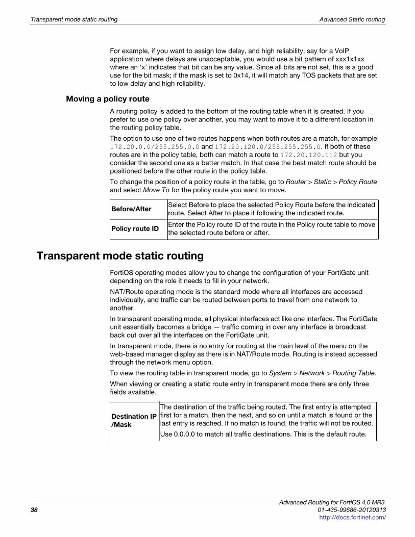
Transparent mode static routing Advanced Static routing
For example, if you want to assign low delay, and high reliability, say for a VoIP
application where delays are unacceptable, you would use a bit pattern of xxx1x1xx
where an ‘x’ indicates that bit can be any value. Since all bits are not set, this is a good
use for the bit mask; if the mask is set to 0x14, it will match any TOS packets that are set
to low delay and high reliability.
Moving a policy route
A routing policy is added to the bottom of the routing table when it is created. If you
prefer to use one policy over another, you may want to move it to a different location in
the routing policy table.
The option to use one of two routes happens when both routes are a match, for example
172.20.0.0/255.255.0.0 and 172.20.120.0/255.255.255.0. If both of these
routes are in the policy table, both can match a route to 172.20.120.112 but you
consider the second one as a better match. In that case the best match route should be
positioned before the other route in the policy table.
To change the position of a policy route in the table, go to Router > Static > Policy Route
and select Move To for the policy route you want to move.
Transparent mode static routing
FortiOS operating modes allow you to change the configuration of your FortiGate unit
depending on the role it needs to fill in your network.
NAT/Route operating mode is the standard mode where all interfaces are accessed
individually, and traffic can be routed between ports to travel from one network to
another.
In transparent operating mode, all physical interfaces act like one interface. The FortiGate
unit essentially becomes a bridge — traffic coming in over any interface is broadcast
back out over all the interfaces on the FortiGate unit.
In transparent mode, there is no entry for routing at the main level of the menu on the
web-based manager display as there is in NAT/Route mode. Routing is instead accessed
through the network menu option.
To view the routing table in transparent mode, go to System > Network > Routing Table.
When viewing or creating a static route entry in transparent mode there are only three
fields available.
Before/AfterSelect Before to place the selected Policy Route before the indicated
route. Select After to place it following the indicated route.
Policy route IDEnter the Policy route ID of the route in the Policy route table to move
the selected route before or after.
Destination IP
/Mask
The destination of the traffic being routed. The first entry is attempted
first for a match, then the next, and so on until a match is found or the
last entry is reached. If no match is found, the traffic will not be routed.
Use 0.0.0.0 to match all traffic destinations. This is the default route.
Advanced Routing for FortiOS 4.0 MR3
38 01-435-99686-20120313
http://docs.fortinet.com/
Advanced Static routing Transparent mode static routing
F
0
h
When configuring routing on a FortiGate unit in transparent mode, remember that all
interfaces must be connected to the same subnet. That means all traffic will be coming
from and leaving on the same subnet. This is important because it limits your static
routing options to only the gateways attached to this subnet. For example, if you only
have one router connecting your network to the Internet then all static routing on the
FortiGate unit will use that gateway. For this reason static routing on FortiGate units in
transparent mode may be a bit different, but it is not as complex as routing in NAT/Route
mode.
GatewaySpecifies the next hop for the traffic. Generally the gateway is the
address of a router on the edge of your network.
Priority
The priority is used if there is more than one match for a route. This
allows multiple routes to be used, with one preferred. If the preferred
route is unavailable the other routes can be used instead.
Valid range of priority can be from 0 to 4 294 967 295.
If more than one route matches and they have the same priority it
becomes an ECMP situation and traffic is shared among those routes.
See “Priority and ECMP” on page 28.
ortiOS™ Handbook v3: Advanced Routing
1-435-99686-20120313 39
ttp://docs.fortinet.com/

Transparent mode static routing Advanced Static routing
Advanced Routing for FortiOS 4.0 MR3
40 01-435-99686-20120313
http://docs.fortinet.com/
F o r t i O S H a n d b o o k
F
0
h
Dynamic Routing OverviewThis section provides an overview of dynamic routing, and how it compares to static
routing. For details on various dynamic routing protocols, see the following chapters for
detailed information.
The following topics are included in this section:
• What is dynamic routing?
• Comparison of dynamic routing protocols
• Choosing a routing protocol
• Dynamic routing terminology
• IPv6 in dynamic routing
What is dynamic routing?
Dynamic routing uses a dynamic routing protocol to automatically select the best route to
put into the routing table. So instead of manually entering static routes in the routing
table, dynamic routing automatically receives routing updates, and dynamically decides
which routes are best to go into the routing table. Its this intelligent and hands-off
approach that makes dynamic routing so useful.
Dynamic routing protocols vary in many ways and this is reflected in the various
administrative distances assigned to routes learned from dynamic routing. These
variations take into account differences in reliability, speed of convergence, and other
similar factors. For more information on these administrative distances, see “Multipath
routing and determining the best route” on page 23.
This section includes:
• Comparing static and dynamic routing
• Dynamic routing protocols
• Minimum configuration for dynamic routing
Comparing static and dynamic routing
A common term used to describe dynamic routing is convergence. Convergence is the
ability to work around a network problems and outages — for the routing to come
together despite obstacles. For example if the main router between two end points goes
down, convergence is the ability to find a way around that failed router and reach the
destination. Static routing has zero convergence beyond trying the next route in its
limited local routing table — if a network administrator doesn’t fix a routing problem
manually, it will never be fixed resulting in a downed network. Dynamic routing solves this
problem by involving routers along the route to the destination in decision making about
the route, and using the routing tables of these routes for potential routes around the
outage. In general dynamic routing has better scalability, robustness, and convergence.
However, the cost of these added benefits include more complexity and some overhead
— bandwidth that is used by the routing protocol for its own administration.
ortiOS™ Handbook v3: Advanced Routing
1-433-98043-20120608 41
ttp://docs.fortinet.com/
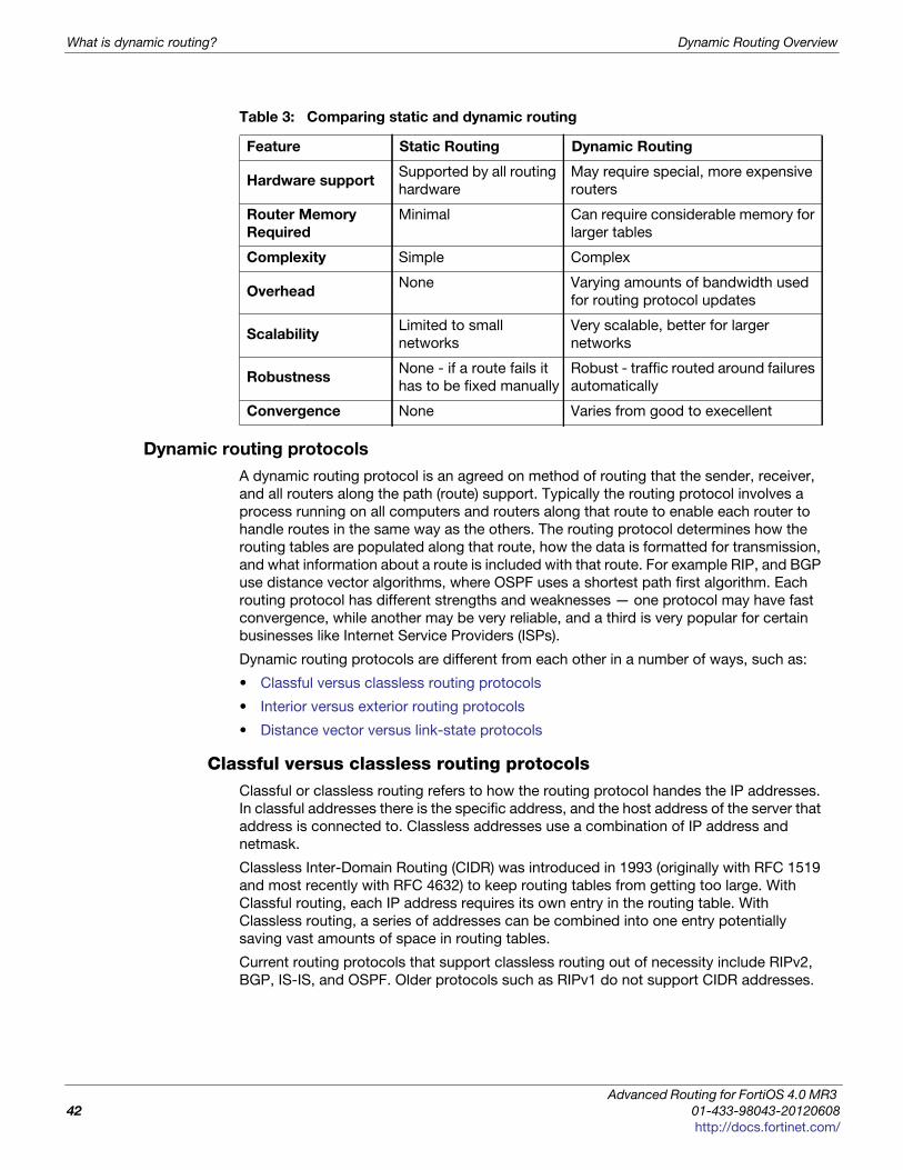
What is dynamic routing? Dynamic Routing Overview
Dynamic routing protocols
A dynamic routing protocol is an agreed on method of routing that the sender, receiver,
and all routers along the path (route) support. Typically the routing protocol involves a
process running on all computers and routers along that route to enable each router to
handle routes in the same way as the others. The routing protocol determines how the
routing tables are populated along that route, how the data is formatted for transmission,
and what information about a route is included with that route. For example RIP, and BGP
use distance vector algorithms, where OSPF uses a shortest path first algorithm. Each
routing protocol has different strengths and weaknesses — one protocol may have fast
convergence, while another may be very reliable, and a third is very popular for certain
businesses like Internet Service Providers (ISPs).
Dynamic routing protocols are different from each other in a number of ways, such as:
• Classful versus classless routing protocols
• Interior versus exterior routing protocols
• Distance vector versus link-state protocols
Classful versus classless routing protocolsClassful or classless routing refers to how the routing protocol handes the IP addresses.
In classful addresses there is the specific address, and the host address of the server that
address is connected to. Classless addresses use a combination of IP address and
netmask.
Classless Inter-Domain Routing (CIDR) was introduced in 1993 (originally with RFC 1519
and most recently with RFC 4632) to keep routing tables from getting too large. With
Classful routing, each IP address requires its own entry in the routing table. With
Classless routing, a series of addresses can be combined into one entry potentially
saving vast amounts of space in routing tables.
Current routing protocols that support classless routing out of necessity include RIPv2,
BGP, IS-IS, and OSPF. Older protocols such as RIPv1 do not support CIDR addresses.
Table 3: Comparing static and dynamic routing
Feature Static Routing Dynamic Routing
Hardware supportSupported by all routing
hardware
May require special, more expensive
routers
Router Memory
Required
Minimal Can require considerable memory for
larger tables
Complexity Simple Complex
OverheadNone Varying amounts of bandwidth used
for routing protocol updates
ScalabilityLimited to small
networks
Very scalable, better for larger
networks
RobustnessNone - if a route fails it
has to be fixed manually
Robust - traffic routed around failures
automatically
Convergence None Varies from good to execellent
Advanced Routing for FortiOS 4.0 MR3
42 01-433-98043-20120608
http://docs.fortinet.com/
Dynamic Routing Overview What is dynamic routing?
F
0
h
Interior versus exterior routing protocolsThe names interior and exterior are very descriptive. Interior routing protocols are
designed for use within a contained network of limited size, where exterior routing
protocols are designed to link multiple networks together. For example, only border
routers of a network run the exterior routing protocol, where all the routers on the network
run the interior protocol. This overlap is required for the exterior routers to communicate
with the interior routers — border routers almost always run multiple routing protocols.
Nearly all routing protocols are interior routing protocols. Only BGP is commonly used as
an exterior routing protocol.
You may see interior gateway protocol (IGP) used to refer to interior routing protocols,
and exterior gateway protocol (EGP) used to refer to interior routing protocols.
Distance vector versus link-state protocolsEvery routing protocol determines the best route between two addresses using a different
method. However, there are two main algorithms for determining the best route —
Distance vector and Link-state.
Distance vector protocolsIn distance vector protocols, routers are told about remote networks through neighboring
routers. The distance part refers to the number of hops to the destination, and in more
advanced routing protocols these hops can be weighted by factors such as available
bandwidth and delay. The vector part determines which router is the next step along the
path for this route. This information is passed along from neighboring routers with routing
update packets that keep the routing tables up to date. Using this method, an outage
along a route is reported back along to the start of that route, ideally before the outage is
encountered.
On distance vector protocols, RFC 1058 which defines RIP v1 states the following:
Distance vector algorithms are based on the exchange of only a small amount of
information. Each entity (gateway or host) that participates in the routing protocol is
assumed to keep information about all of the destinations within the system.
Generally, information about all entities connected to one network is summarized by a
single entry, which describes the route to all destinations on that network.
There are four main weaknesses inherent in the distance vector method. Firstly, the
routing information is not discovered by the router itself, but is instead reported
information that must be relied on to be accurate and up-to-date. The second weakness
is that it can take a while for the information to make its way to all the routers who need
the information — in other words it can have slow convergence. The third weakness is
the amount of overhead involved in passing these updates all the time. The number of
updates between routers in a larger network can significantly reduce the available
bandwidth. The fourth weakness is that distance vector protocols can end up with
routing-loops. Routing loops are when packets are routed for ever around a network, and
often occur with slow convergence. The bandwidth required by these infinite loops will
slow your network to a halt. There are methods of preventing these loops however, so
this weakness is not as serious as it may first appear.
Link-state protocolsLink-state protocols are also known as shortest path first protocols. Where distance
vector uses information passed along that may or may not be current and accurate, in
link-state protocols each router passes along only information about networks and
devices directly connected to it. This results in a more accurate picture of the network
topology around your router, allowing it to make better routing decisions. This information
ortiOS™ Handbook v3: Advanced Routing
1-433-98043-20120608 43
ttp://docs.fortinet.com/
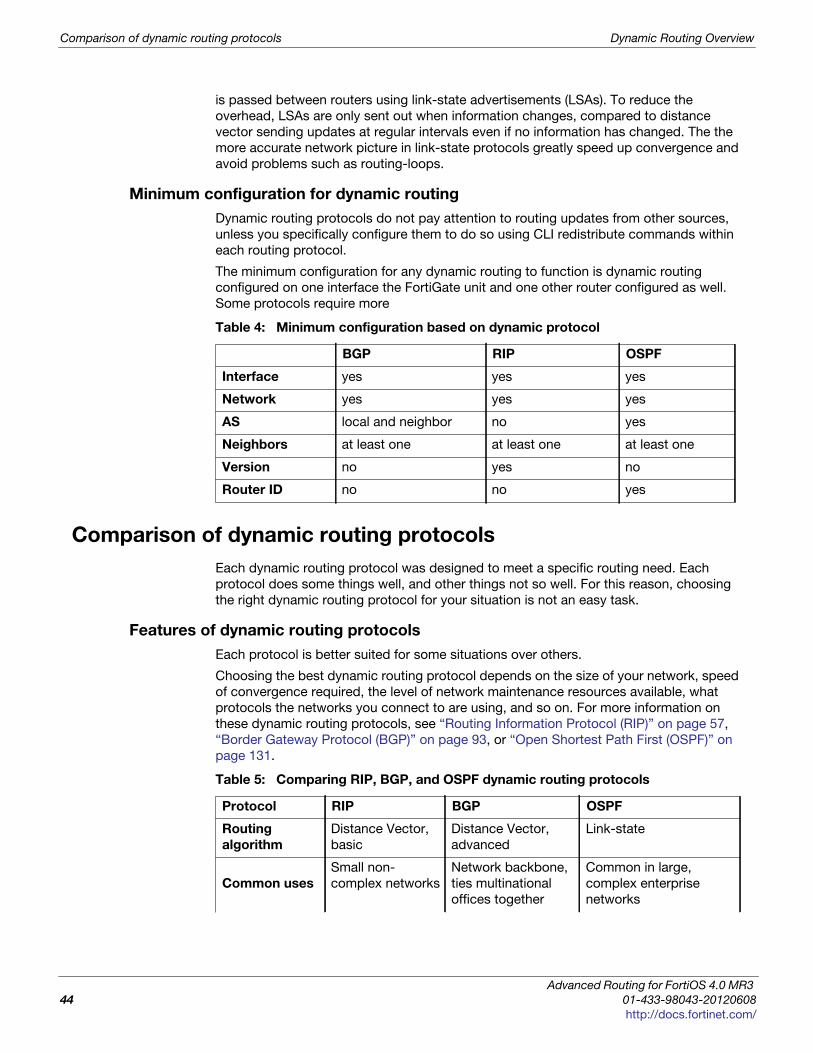
Comparison of dynamic routing protocols Dynamic Routing Overview
is passed between routers using link-state advertisements (LSAs). To reduce the
overhead, LSAs are only sent out when information changes, compared to distance
vector sending updates at regular intervals even if no information has changed. The the
more accurate network picture in link-state protocols greatly speed up convergence and
avoid problems such as routing-loops.
Minimum configuration for dynamic routing
Dynamic routing protocols do not pay attention to routing updates from other sources,
unless you specifically configure them to do so using CLI redistribute commands within
each routing protocol.
The minimum configuration for any dynamic routing to function is dynamic routing
configured on one interface the FortiGate unit and one other router configured as well.
Some protocols require more
Comparison of dynamic routing protocols
Each dynamic routing protocol was designed to meet a specific routing need. Each
protocol does some things well, and other things not so well. For this reason, choosing
the right dynamic routing protocol for your situation is not an easy task.
Features of dynamic routing protocols
Each protocol is better suited for some situations over others.
Choosing the best dynamic routing protocol depends on the size of your network, speed
of convergence required, the level of network maintenance resources available, what
protocols the networks you connect to are using, and so on. For more information on
these dynamic routing protocols, see “Routing Information Protocol (RIP)” on page 57,
“Border Gateway Protocol (BGP)” on page 93, or “Open Shortest Path First (OSPF)” on
page 131.
Table 4: Minimum configuration based on dynamic protocol
BGP RIP OSPF
Interface yes yes yes
Network yes yes yes
AS local and neighbor no yes
Neighbors at least one at least one at least one
Version no yes no
Router ID no no yes
Table 5: Comparing RIP, BGP, and OSPF dynamic routing protocols
Protocol RIP BGP OSPF
Routing
algorithm
Distance Vector,
basic
Distance Vector,
advanced
Link-state
Common uses
Small non-
complex networks
Network backbone,
ties multinational
offices together
Common in large,
complex enterprise
networks
Advanced Routing for FortiOS 4.0 MR3
44 01-433-98043-20120608
http://docs.fortinet.com/
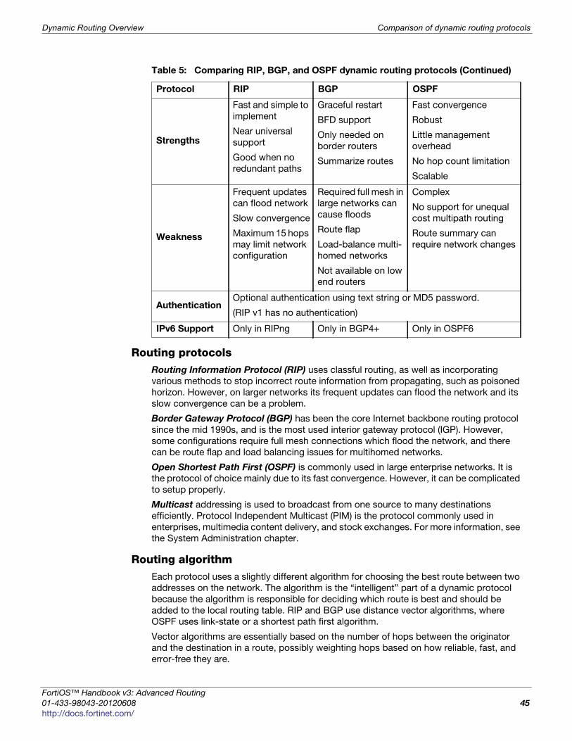
Dynamic Routing Overview Comparison of dynamic routing protocols
F
0
h
Routing protocolsRouting Information Protocol (RIP) uses classful routing, as well as incorporating
various methods to stop incorrect route information from propagating, such as poisoned
horizon. However, on larger networks its frequent updates can flood the network and its
slow convergence can be a problem.
Border Gateway Protocol (BGP) has been the core Internet backbone routing protocol
since the mid 1990s, and is the most used interior gateway protocol (IGP). However,
some configurations require full mesh connections which flood the network, and there
can be route flap and load balancing issues for multihomed networks.
Open Shortest Path First (OSPF) is commonly used in large enterprise networks. It is
the protocol of choice mainly due to its fast convergence. However, it can be complicated
to setup properly.
Multicast addressing is used to broadcast from one source to many destinations
efficiently. Protocol Independent Multicast (PIM) is the protocol commonly used in
enterprises, multimedia content delivery, and stock exchanges. For more information, see
the System Administration chapter.
Routing algorithmEach protocol uses a slightly different algorithm for choosing the best route between two
addresses on the network. The algorithm is the “intelligent” part of a dynamic protocol
because the algorithm is responsible for deciding which route is best and should be
added to the local routing table. RIP and BGP use distance vector algorithms, where
OSPF uses link-state or a shortest path first algorithm.
Vector algorithms are essentially based on the number of hops between the originator
and the destination in a route, possibly weighting hops based on how reliable, fast, and
error-free they are.
Strengths
Fast and simple to
implement
Near universal
support
Good when no
redundant paths
Graceful restart
BFD support
Only needed on
border routers
Summarize routes
Fast convergence
Robust
Little management
overhead
No hop count limitation
Scalable
Weakness
Frequent updates
can flood network
Slow convergence
Maximum 15 hops
may limit network
configuration
Required full mesh in
large networks can
cause floods
Route flap
Load-balance multi-
homed networks
Not available on low
end routers
Complex
No support for unequal
cost multipath routing
Route summary can
require network changes
AuthenticationOptional authentication using text string or MD5 password.
(RIP v1 has no authentication)
IPv6 Support Only in RIPng Only in BGP4+ Only in OSPF6
Table 5: Comparing RIP, BGP, and OSPF dynamic routing protocols (Continued)
Protocol RIP BGP OSPF
ortiOS™ Handbook v3: Advanced Routing
1-433-98043-20120608 45
ttp://docs.fortinet.com/
Comparison of dynamic routing protocols Dynamic Routing Overview
The link-state algorithm used by OSPF is called the Dijkstra algorithm. Link-state treats
each interface as a link, and records information about the state of the interface. The
Dijkstra algorithm creates trees to find the shortest paths to the routes it needs based on
the total cost of the parts of the routes in the tree.
For more information on the routing algorithm used, see “Distance vector versus link-
state protocols” on page 43.
AuthenticationIf an attacker gains access to your network, they can masquerade as a router on your
network to either gain information about your network or disrupt network traffic. If you
have a high quality firewall configured, it will help your network security and stop many of
this type of threat. However, the main method for protecting your routing information is to
use authentication in your routing protocol. Using authentication on your FortiGate unit
and other routers prevents access by attackers — all routers must authenticate with
passwords, such as MD5 hash passwords, to ensure they are legitimate routers.
When configuring authentication on your network, ensure you configure it the same on all
devices on the network. Failure to do so will create errors and outages as those forgotten
devices fail to connect to the rest of the network.
For example, to configure an MD5 key of 123 on an OSPF interface called ospf_test,
enter the following CLI command:
config router ospfconfig ospf-interfaceedit ospf_testset authentication md5set md5-key 123
endend
ConvergenceConvergence is the ability of a networking protocol to re-route around network outages.
Static routing cannot do this. Dynamic routing protocols can all converge, but take
various amounts of time to do this. Slow convergence can cause problems such as
network loops which degrade network performance.
You may also hear robustness and redundancy used to describe networking protocols. In
many ways they are the same thing as convergence. Robustness is the ability to keep
working even though there are problems, including configuration problems as well as
network outages. Redundancy involves having duplicate parts that can continue to
function in the event of some malfunction, error, or outage. It is relatively easy to
configure dynamic routing protocols to have backup routers and configurations that will
continue to function no matter the network problem short of a total network failure.
IPv6 SupportIPv4 addressing is in common use everywhere around the world. IPv6 has much larger
addresses and it is used by many large companies and government departments. IPv6 is
not as common as IPv4 yet, but more companies are adopting it.
If your network uses IPv6, your dynamic routing protocol must support it. None of the
dynamic routing protocols originally supported IPv6, but they all have additions,
expansions, or new versions that do support IPv6. For more information, see “RIP and
IPv6” on page 58, “BGP and IPv6” on page 94, or “OSPF and IPv6” on page 132.
Advanced Routing for FortiOS 4.0 MR3
46 01-433-98043-20120608
http://docs.fortinet.com/
Dynamic Routing Overview Comparison of dynamic routing protocols
F
0
h
When to adopt dynamic routing
Static routing is more than enough to meet your networking needs when you have a small
network. However, as your network grows, the question you need to answer is at what
point do you adopt dynamic routing in your networking plan and start using it in your
network? The main factors in this decision are typically:
• Budget
• Current network size and topology
• Expected network growth
• Available resources for ongoing maintenance
BudgetWhen making any business decision, the budget must always be considered. Static
routing does not involve special hardware, fancy software, or expensive training courses.
Dynamic routing can include all of these extra expenses. Any new routing hardware such
as routers and switches need to support your chosen protocols. Network management
software to help configure and maintain your more complex network, and routing
protocol drivers may be necessary as well. If the network administrators are not well
versed in dynamic routing, either a training course or some hands on learning time must
be budgeted so they can administer the new network with confidence. Together, these
factors will use up your budget quickly.
Additionally people account for network starting costs in the budgets, but usually leave
out the ongoing cost of network maintenance. Any budget must provide for the hours
that will be spent on updating the network routing equipment, and fixing any problems.
Without that money in the budget, you may end up back at static routing before you
know it.
Current network size and topologyAs stated earlier static routing works well on small networks. At those networks get larger,
routing takes longer, routing tables get very large, and general performance isn’t what it
could be.
Topology is a concern as well. If all your computers are in one building, its much easier to
stay with static routing longer. However, connecting a number of locations will be easier
with the move to dynamic routing.
If you have a network of 20 computers, you can still likely use static routing. If those
computers are in two or three locations, static routing will still be a good choice for
connecting them. Also, if you just connect to your ISP and don’t worry about any special
routing to do that, you are likely safe with just static routing.
If you have a network of 100 computers in one location, you can use static routing but it
will be getting slower, more complex, and there won’t be much room for expansion. If
those 100 computers are spread across three or more locations, dynamic routing is the
way to go.
If you have 1000 comptuers, you definitely need to use dynamic routing no matter how
many locations you have.
Hopefully this section has given you an idea of what results you will likely experience from
different sized networks using different routing protocols. Your choice of which dynamic
routing protocol to use is partly determined by the network size, and topology.
ortiOS™ Handbook v3: Advanced Routing
1-433-98043-20120608 47
ttp://docs.fortinet.com/
Comparison of dynamic routing protocols Dynamic Routing Overview
Expected network growthYou may not be sure if your current network is ready for dynamic routing. However, if you
are expecting rapid growth in the near future, it is a good idea to start planning for that
growth now so you are ready for the coming expansion.
Static routing is very labor intensive. Each network device’s routing table needs to be
configured and maintained manually. If there is a large number of new computers being
added to the network, they each need to have the static routing table configured and
maintained. If devices are being moved around the network frequently, they must also be
updated each time.
Instead, consider putting dynamic routing in place before those new computers are
installed on the network. The installation issues can be worked out with a smaller and
less complex network, and when those new computers or routers are added to the
network there will be nowhere near the level of manual configuration required. Depending
on the level of growth, this labor savings can be significant. For example, in an
emergency you can drop a new router into a network or AS wait for it to receive the
routing updates from its neighbors, and then remove one of the neighbors. While the
routes will not be the most effective possible, this method is much less work than static
routing in the same situation with less chance of mistakes.
Also as your network grows and you add more routers, those new routers can help share
the load in most dynamic routing configurations. For example if you have 4 OSPF routers
and 20,000 external routes those few routers will be overwhelmed. But in a network with
15 OSPF routers they will better be able to handle that number of routes. Be aware
though that adding more routers to your network will increase the amount of updates
sent between the routers, which will take up some of your bandwidth.
Available resources for ongoing maintenanceAs touched on in the budget section, there must be resources dedicated to ongoing
network maintenance, upgrades, and troubleshooting. These resources include
administrator hours to configure and maintain the network, training for the administrator if
needed, extra hardware and software as needed, and possible extra staff to help the
administrator in emergencies. Without these resources, you will quickly find the network
reverting to static routing out of necessity. This is because:
• Routing software updates will require time.
• Routing hardware updates will require time.
• Office reorganizations or significant personnel movement will require time from a
networking point of view.
• Networking problems that occur, such as failed hardware, require time to locate and
fix the problem.
If the resources to accomplish these tasks are not budgeted, they will either not happen
or not happen at the required level to continue operation. This will result in both the
network administration staff and the network users being very frustrated.
A lack of maintenance budget will also result in increasingly heavy reliance on static
routing as the network administrators are forced to use quick fixes for problems that
come up. This invariably involves going to static routing, and dropping the more complex
and time consuming dynamic routing.
Advanced Routing for FortiOS 4.0 MR3
48 01-433-98043-20120608
http://docs.fortinet.com/
Dynamic Routing Overview Comparison of dynamic routing protocols
F
0
h
Choosing a routing protocol
One of that hardest decisions in routing can be choosing which routing protocol to use on
your network. It can be easy to decide when static routing will not meet your needs, but
how can you tell which dynamic routing protocol is best for your network and situation?
Here is a brief look at the routing protocols including their strongest and weakest points.
The steps to choosing your routing protocol are:
1 Answer questions about your network
2 Dynamic routing terminology
3 Evaluate your chosen protocol
4 Implement your dynamic routing protocol
Answer questions about your networkBefore you can decide what is best for your situation, you need to examine what the
details of your situation are such as what you have for budget, equipment, and users.
The following questions will help you form a clear idea of your routing needs:
How many computers or devices are on your network?
It matters if you only have a few computers, or if you have many and if they are all at one
location or not as well. All routing protocols can be run on any sized network, however it
can be inefficient to run some on very small networks. However, routers and network
hardware that support dynamic routing can be more expensive than more generic routers
for static routing.
What applications typically run over the network?
Finding out what application your users are running will help you determine their
needs and the needs of the network regarding bandwidth, quality of service, and other
such issues.
What level of service to the users expect from the network?
Different network users have different expectations of the network. Its not critical for
someone surfing the Internet to have 100% uptime, but it is required for a stock
exchange network or a hospital.
Is there network expansion in your near future?
You may have a small network now, but if it will be growing quickly, you should plan
for the expected size so you don’t have to chance technologies again down the road.
What routing protocols do your networks connect to?
This is most often how routing protocol decisions are made. You need to be able to
communicate easily with your service provider and neighbors, so often people simply
use what everyone else is using.
Is security a major concern?
Some routing protocols have levels of authentication and other security features built
in. Others do not. If security is important to you, be aware of this.
What is your budget — both initial and maintenance?
More robust and feature laden routing protocols generally mean more resources are
required to keep them working well. Also more secure configurations require still more
resources. This includes both set up costs, as well as ongoing maintenance costs.
Ignore these costs at the risk of having to drop the adoption of the new routing
protocol mid-change.
ortiOS™ Handbook v3: Advanced Routing
1-433-98043-20120608 49
ttp://docs.fortinet.com/
Dynamic routing terminology Dynamic Routing Overview
Evaluate your chosen protocolOnce you have examined the features of the routing protocols listed above and chosen
the one that best meets your needs, you can set up an evaluation or test install of that
protocol.
The test install is generally set up in a sandbox configuration so it will not affect critical
network traffic. The aim of the test install is to prove that it will work on a larger scale on
your network. So be sure that the test install mirrors your larger network well enough for
you to discover any problems. If its too simplistic, these problems may not appear.
If your chosen protocol does not meet your goals choose a different protocol and repeat
the evaluation process until either a protocol meets your needs, or you change your
criteria.
Implement your dynamic routing protocolYou have examined your needs, selected the best matching dynamic routing protocol,
tested it, and now you are ready to implement it with confidence.
This guide will help you configure your FortiGate unit to support your chosen dynamic
routing protocol. Refer to the various sections in this guide as needed during your
implementation to help ensure a smooth transition. Examples for each protocol have
been included to show proper configurations for different types of networks.
Dynamic routing terminology
Dynamic routing is a complex subject. There are many routers on different networks and
all can be configured differently. It become even more complicated when you add to this
each routing protocol having slightly different names for similar features, and many
configurable features for each protocol.
To better understand dynamic routing, here are some explanations of common dynamic
routing terms.
• Aggregated routes and addresses
• Autonomous system (AS)
• Area border router (ABR)
• Neighbor routers
• Route maps
• Access lists
• Bi-directional forwarding detection (BFD)
For more details on a term as it applies to a dynamic routing protocol, see one of “Border
Gateway Protocol (BGP)” on page 93, “Routing Information Protocol (RIP)” on page 57,
or “Open Shortest Path First (OSPF)” on page 131.
Aggregated routes and addressesJust as an aggregate interface combines multiple interfaces into one virtual interface, an
aggregate route combines multiple routes into one. This reduces the amount of space
those routes require in the routing tables of the routers along that route. The trade-off is a
small amount of processing to aggregate and de-aggregate the routes at either end.
Advanced Routing for FortiOS 4.0 MR3
50 01-433-98043-20120608
http://docs.fortinet.com/
Dynamic Routing Overview Dynamic routing terminology
F
0
h
The benefit of this method is that you can combine many addresses into one, potentially
reducing the routing table size immensely. The weakness of this method is if there are
holes in the address range you are aggregating you need to decide if its better to break it
into multiple ranges, or accept the possibility of failed routes to the missing addresses.
To manually aggregate the range of IP addresses from 192.168.1.100 to
192.168.1.103
1 Convert the addresses to binary
192.168.1.100 = 11000000 10101000 00000001 01100100192.168.1.101 = 11000000 10101000 00000001 01100101192.168.1.102 = 11000000 10101000 00000001 01100110192.168.1.103 = 11000000 10101000 00000001 01100111
2 Determine the maximum number of matching bits common to the addresses.
There are 30-bits in common, with only the last 2-bits being different.
3 Record the common part of the address.
11000000 10101000 00000001 0110010X = 192.168.1.100
4 For the netmask, assume all the bits in the netmask are 1 except those that are
different which are 0.
11111111 11111111 11111111 11111100 = 255.255.255.252
5 Combine the common address bits and the netmask.
192.168.1.100/255.255.255.252
Alternately the IP mask may be written as a single number:
192.168.1.100/2
6 As required, set variables and attributes to declare the routes have been aggregated,
and what router did the aggregating.
Autonomous system (AS)An Autonomous System (AS) is one or more connected networks that use the same
routing protocol, and appear to be a single unit to any externally connected networks. For
example an ISP may have a number of customer networks connected to it, but to any
networks connected externally to the ISP it appears as one system or AS. An AS may
also be referred to as a routing domain.
It should be noted that while OSPF routing takes place within one AS, the only part of
OSPF that deals with the AS is the AS border router (ASBR).
There are multiple types of AS defined by how they are connected to other ASes. A
multihomed AS is connected to at least two other ASes and has the benefit of
redundancy — if one of those ASes goes down, your AS can still reach the Internet
through its other connection. A stub AS only has one connection, and can be useful in
specific configurations where limited access is desirable.
Each AS has a number assigned to it, known as an ASN. In an internal network, you can
assign any ASN you like (a private AS number), but for networks connected to the
Internet (public AS) you need to have an officially registered ASN from Internet Assigned
Numbers Authority (IANA). ASNs from 1 to 64,511 are designated for public use.
As of January 2010, AS numbers are 4 bytes long instead of the former 2 bytes.
RFC 4893 introduced 32-bit ASNs, which FortiGate units support for BGP and OSPF.
ortiOS™ Handbook v3: Advanced Routing
1-433-98043-20120608 51
ttp://docs.fortinet.com/
Dynamic routing terminology Dynamic Routing Overview
Do you need your own AS?The main factors in deciding if you need your own AS or if you should be part of someone
else’s are:
• exchanging external routing information
• many prefixes should exist in one AS as long as they use the same routing policy
• when you use a different routing protocol than your border gateway peers (for
example your ISP uses BGP, and you use OSPF)
• connected to multiple other AS (multi-homed)
You should not create an AS for each prefix on your network. Neither should you be
forced into an AS just so someone else can make AS-based policy decisions on your
traffic.
There can be only one AS for any prefix on the Internet. This is to prevent routing issues.
What AS number to use?In addition to overseeing IP address allocation and Domain Name Systems (DNS), the
Internet Assigned Numbers Authority (IANA) assigns public AS numbers. The public AS
numbers are from 1 to 64,511. The ASNs 0, 54272–64511, and 65535 are reserved by the
IANA. These ASNs should not be used.
ASNs are assigned in blocks by the Internet Assigned Numbers Authority (IANA) to
Regional Internet Registries (RIRs) who then assign ASNs to companies within that RIRs
geographic area. Usually these companies are ISPs, and to receive an ASN you must
complete the application process of the local RIR and be approved before being
assigned an ASN. The RIRs names and regions are:
AS numbers from 64512 to 65534 are reserved for private use. Private AS numbers can
be used for any internal networks with no outside connections to the Internet such as test
networks, classroom labs, or other internal-only networks that do not access the outside
world. You can also configure border routers to filter out any private ASNs before routing
traffic to the outside world. If you must use private ASNs with public networks, this is the
only way to configure them. However, it is risky because many other private networks
could be using the same ASNs and conflicts will happen. It would be very much like your
local 192.168.0.0 network being made public — the resulting problems would be
widespread.
In 1996, when RFC 1930 was written only 5,100 ASes had been allocated and a little
under 600 ASes were actively routed in the global Internet. Since that time many more
public ASNs have been assigned, leaving only a small number. For this reason 32-bit
ASNs (four-octet ASNs) were defined to provide more public ASNs. RFC 4893 defines
32-bit ASNs, and FortiGate units support these larger ASNs as of FortiOS version 4.2
AFRINIC Serves the African continent
APNIC Asia-Pacific including China, India, and Japan
ARIN American registry including Canada and United States
LACNIC Latin America, including Mexico, Caribbean, Central and South America
RIPE NCC Europe, the Middle East, former USSR, and parts of Central Asia
Advanced Routing for FortiOS 4.0 MR3
52 01-433-98043-20120608
http://docs.fortinet.com/
Dynamic Routing Overview Dynamic routing terminology
F
0
h
Area border router (ABR)Routers within an AS advertise updates internally and only to each other. However,
routers on the edge of the AS must communicate both with routers inside their AS and
with routers external to their AS, often running a different routing protocol. These routers
are called Area Border Routers (ABRs) or edge routers. Often ABRs run multiple routing
protocols to be able to redistribute traffic between different ASes that are running
different protocols, such as the edge between an ISP’s IS-IS routing network and an large
company’s OSPF network.
OSPF defines ABRs differently from other routers. In OSPF, an ABR is an OSPF router
that connects another AS to the backbone AS, and is a member of all the areas it
connects to. An OSPF ABR maintains a LSA database for each area that it is connected
to. The concept of the edge router is present, but its the edge of the backbone instead of
the edge of the OSPF supported ASes.
Neighbor routersRouting involves routers communicating with each other. To do this, routers need to know
information about each other. These routers are called neighbor routers, and are
configured in each routing protocol. Each neighbor has custom settings since some
routers may have functionality others routers lack. Neighbour routers are sometimes
called peers.
Generally neighbor routers must be configured, and discovered by the rest of the network
before they can be integrated to the routing calculations. This is a combination of the
network administrator configuring the new router with its neighbor router addresses, and
the routing network discovering the new router, such as the hello packets in OSPF. That
discovery initiates communication between the new router and the rest of the network.
Route mapsRoute maps are a way for the FortiGate unit to evaluate optimum routes for forwarding
packets or suppressing the routing of packets to particular destinations. Compared to
access lists, route maps support enhanced packet-matching criteria. In addition, route
maps can be configured to permit or deny the addition of routes to the FortiGate unit
routing table and make changes to routing information dynamically as defined through
route-map rules.
Route maps can be used for limiting both received route updates, and sent route
updates. This can include the redistribution of routes learned from other types of routing.
For example if you don’t want to advertise local static routes to external networks, you
could use a route map to accomplish this.
The FortiGate unit compares the rules in a route map to the attributes of a route. The
rules are examined in ascending order until one or more of the rules in the route map are
found to match one or more of the route attributes.
As an administrator, route maps allow you to group a set of addresses together and
assign them a meaningful name. Then during your configuration, you can use these
route-maps to speed up configuration. The meaningful names ensure fewer mistakes
during configuration as well.
The default rule in the route map (which the FortiGate unit applies last) denies all routes.
For a route map to take effect, it must be called by a FortiGate unit routing process.
The syntax for route maps are:
config router route-mapedit <route_map_name>set comments
ortiOS™ Handbook v3: Advanced Routing
1-433-98043-20120608 53
ttp://docs.fortinet.com/
Dynamic routing terminology Dynamic Routing Overview
config ruleedit <route_map_rule_id>set action set match-*set set-*
The match-* commands allow you to match various parts of a route. The set-*
commands allow you to set routing information once a route is matched.
For an example of how route maps can be used to create receiving or sending “groups”
in routing, see “Redistributing and blocking routes in BGP” on page 123.
Access listsUse this command to add, edit, or delete access lists. Access lists are filters used by
FortiGate unit routing processes. For an access list to take effect, it must be called by a
FortiGate unit routing process (for example, a process that supports RIP or OSPF). Use
access-list6 for IPv6 routing.
Access lists can be used to filter which updates are passed between routers, or which
routes are redistributed to different networks and routing protocols. You can create lists
of rules that will match all routes for a specific router or group of routers.
Each rule in an access list consists of a prefix (IP address and netmask), the action to
take for this prefix (permit or deny), and whether to match the prefix exactly or to match
the prefix and any more specific prefix.
The FortiGate unit attempts to match a packet against the rules in an access list starting
at the top of the list. If it finds a match for the prefix, it takes the action specified for that
prefix. If no match is found the default action is deny.
The syntax for access lists is:
config router access-list, access-list6edit <access_list_name>set commentsconfig ruleedit <access_list_id>set actionset exact-matchset prefixset prefix6set wildcard
For an example of how access lists can be used to create receiving or sending “groups”
in routing, see “Redistributing and blocking routes in BGP” on page 123.
Bi-directional forwarding detection (BFD)Bi-directional Forwarding Detection (BFD) is a protocol used to quickly locate hardware
failures in the network. Routers running BFD send packets to each other at a negotiated
rate. If packets from a BFD-protected router fail to arrive, then that router is declared
down. BFD communicates this information to the routing protocol and the routing
information is updated.
If you are setting a prefix of 128.0.0.0, use the format 128.0.0.0/1. The default route,
0.0.0.0/0 can not be exactly matched with an access-list. A prefix-list must be used for
this purpose.
Advanced Routing for FortiOS 4.0 MR3
54 01-433-98043-20120608
http://docs.fortinet.com/
Dynamic Routing Overview IPv6 in dynamic routing
F
0
h
BFD neighbors establish if BFD is enabled in OSPF or BFP routers that establish as
neighbors.
The CLI commands associated with BFD include:
config router bgpconfig neighborset bfd
config router ospfset bfd
Per-VDOM configuration:
config system settingsset bfd set bfd-desired-min-tx set bfd-required-min-rx set bfd-detect-mult set bfd-dont-enforce-src-port
Per-interface (override) configuration:
config system interfaceedit <interface_name>set bfd enableset bfd-desired-min-tx set bfd-detect-mult set bfd-required-min-rx
For more information about BFD in BGP, see “Bi-directional forwarding detection (BFD)”
on page 108.
IPv6 in dynamic routing
Unless otherwise stated, routing protocols apply to IPv4 addressing. This is the standard
address format used. However, IPv6 is becoming popular and new versions of the
dynamic routing protocols have been introduced.
As of FortiOS v4.1, dynamic routing supports IPv6 on your FortiGate unit. The new
versions of these protocols and the corresponding RFCs are:
• BGP4+ — RFC 2545, and RFC 2858 Multiprotocol Extensions for IPv6 Inter-Domain
Routing, and Multiprotocol Extensions for BGP-4 (MP-BGP) respectively. See “BGP
and IPv6” on page 94
• RIP next generation (RIPng) — RFC 2080 - Routing Information Protocol next
generation (RIPng). See “RIP and IPv6” on page 58.
• OSPFv3 — RFC 2740 Open Shortest Path First version 3 (OSPFv3) for IPv6 support.
See “OSPF and IPv6” on page 132.
As with most advanced routing features on your Fortigate unit, IPv6 settings for dynamic
routing protocols are CLI-only. To configure IPv6 for RIP, BGP, or OSPF protocols you
must use the CLI commands.
ortiOS™ Handbook v3: Advanced Routing
1-433-98043-20120608 55
ttp://docs.fortinet.com/

IPv6 in dynamic routing Dynamic Routing Overview
Advanced Routing for FortiOS 4.0 MR3
56 01-433-98043-20120608
http://docs.fortinet.com/
F o r t i O S H a n d b o o k
F
0
h
Routing Information Protocol (RIP)This section describes the Routing Information Protocol (RIP).
The following topics are included in this section:
• RIP background and concepts
• Troubleshooting RIP
• RIP routing examples
RIP background and concepts
This section contains:
• Background
• Parts and terminology of RIP
• How RIP works
Background
Routing Information Protocol (RIP) is a distance-vector routing protocol intended for
small, relatively homogeneous networks. Its widespread use started when an early
version of RIP was included with BSD v4.3 Linux as the routed daemon. The routing
algorithm used by RIP, the Bellman–Ford algorithm, first saw widespread use as the initial
routing algorithm of the ARPANET.
RIP benefits include being well suited to smaller networks, is in widespread use, near
universal support on routing hardware, quick to configure, and works well if there are no
redundant paths. However, RIP updates are sent out node-by-node so it can be slow to
find a path around network outages. RIP also lacks good authentication, can not choose
routes based on different quality of service methods, and can create network loops if you
are not careful.
The FortiGate implementation of RIP supports RIP version 1 (see RFC 1058), RIP version
2 (see RFC 2453), and the IPv6 version RIPng (see RFC 2080).
RIP v1In 1988 RIP version 1, defined in RFC 1058, was released. The RFC even states that RIP
v1 is based on Linux routed due to it being a “defacto standard”.
It uses classful addressing and uses broadcasting to send out updates to router
neighbors. There is no subnet information included in the routing updates in classful
routing, and it does not support CIDR addressing — subnets must all be the same size.
Also, route summarization is not possible.
RIP v1 has no router authentication method, so it is vulnerable to attacks through packet
sniffing, and spoofing.
ortiOS™ Handbook v3: Advanced Routing
1-435-99686-20120313 57
ttp://docs.fortinet.com/
RIP background and concepts Routing Information Protocol (RIP)
RIP v2In 1993, RIP version 2 was developed to deal with the limitations of RIP v1. It was not
standardized until 1998. This new version supports classless routing, and subnets of
various sizes.
Router authentication was added in RIP v2 — it supports MD5. MD5 hashes are an older
encryption method, but this is much improved over no security at all.
In RIP v2 the hop count limit remained at 15 to be backwards compatible with RIP v1.
RIP v2 uses multicasting to send the entire routing table to router neighbors, thereby
reducing the traffic for devices that are not participating in RIP routing.
Routing tags were added as well, which allow internal routes or redistributed routes to be
identified as such.
RIPngRIPng, defined in RFC 2080, is an extension of RIP2 designed to support IPv6. However,
RIPng varies from RIPv2 in that it is not fully backwards compatible with RIPv1.
• RIPng does not support RIPv1 update authentication, it relies on IPsec
• RIPng does not allow attaching tags to routes as in RIPv2
• RIPng requires specific encoding of the next hop for a set of route entries, unlike
RIPv2 that encodes the next-hop into each route entry .
Parts and terminology of RIP
Before you can understand how RIP functions, you need to understand some of the main
concepts and parts of RIP.
This section includes:
• RIP and IPv6
• Default information originate option
• Garbage, timeout, and update timers
• Authentication and key-chain
• Access Lists
RIP and IPv6RIP Next Generation (RIPng) is a new version of RIP was released that includes support
for IPv6.
The FortiGate unit command config router ripng is almost the same as config router rip, except that IPv6 addresses are used. Also if you are going to use prefix or
access lists with RIPng, you must use the config router access-list6 or config prefix-list6 versions of those commands.
If you want to troubleshoot RIPng, it is the same as with RIP but specify the different
protocol, and use IPv6 addresses. This applies to commands such as get router info6 when you want to see the routing table, or other related information.
If you want to route IPv4 traffic over an IPv6 network, you can use the command config
system ip6-tunnel to configure the FortiGate unit to do this. The IPv6 interface is
configured under config system interface. All subnets between the source and
destination addresses must support IPv6. This command is not supported in Transparent
mode.
Advanced Routing for FortiOS 4.0 MR3
58 01-435-99686-20120313
http://docs.fortinet.com/
Routing Information Protocol (RIP) RIP background and concepts
F
0
h
For example, you want to set up a tunnel on the port1 interface starting at
2002:C0A8:3201:: on your local network and tunnel it to address 2002:A0A:A01:: where it
will need access to an IPv4 network again. Use the following command:
config system ipv6-tunneledit test_tunnelset destination 2002:A0A:A01::set interface port1set source 2002:C0A8:3201::
endend
The CLI commands associated with RIPng include:
config router ripngconfig router access-list6config router prefix-list6config system ipv6-tunnelget router info6 *
Default information originate optionThis is the second advanced option for RIP in the web-based manager, right after metric.
Enabling default-information-originate will generate and advertise a default route into the
FortiGate unit’s RIP-enabled networks. The generated route may be based on routes
learned through a dynamic routing protocol, routes in the routing table, or both. RIP does
not create the default route unless you use the always option.
Select Disable if you experience any issues or if you wish to advertise your own static
routes into RIP updates.
The CLI commands associated with default information originate include:
config router ripset default-information-originate
end
Garbage, timeout, and update timersRIP uses various timers to regulate its performance including a garbage timer, timeout
timer, and update timer. The FortiGate unit default timer settings (30, 180, and 120
seconds respectively) are effective in most configurations — if you change these settings,
ensure that the new settings are compatible with local routers and access servers.
The CLI commands associated with garbage, timeout, and update timers include:
config router ripset garbage-timerset timeout-timerset update-timer
end
The Timeout period should be at least three times longer than the Update period. If the
Update timer is smaller than Timeout or Garbage timers, you will experience an error.
ortiOS™ Handbook v3: Advanced Routing
1-435-99686-20120313 59
ttp://docs.fortinet.com/
RIP background and concepts Routing Information Protocol (RIP)
Garbage timerThe garbage timer is the amount of time (in seconds) that the FortiGate unit will advertise
a route as being unreachable before deleting the route from the routing table. If this timer
is shorter, it will keep more up-to-date routes in the routing table and remove old ones
faster. This will result in a smaller routing table which is useful if you have a very large
network, or if your network changes frequently.
Update timerThe update timer determines the interval between routing updates. Generally, this value is
set to 30 seconds. There is some randomness added to help prevent network traffic
congestion, which could result from all routers simultaneously attempting to update their
neighbors. The update timer should be at least three times smaller than the timeout timer,
otherwise you will experience an error.
If you are experiencing significant RIP traffic on your network, you can increase this
interval to send fewer updates per minute. However, ensure you increase the interval for
all the routers on your network or you will experience time outs that will degrade your
network speed.
Timeout timerThe timeout timer is the maximum amount of time (in seconds) that a route is considered
reachable while no updates are received for the route. This is the maximum time the
FortiGate unit will keep a reachable route in the routing table while no updates for that
route are received. If the FortiGate unit receives an update for the route before the
timeout period expires, the timer is restarted. The timeout period should be at least three
times longer than the depute period, otherwise you will experience an error.
If you are experiencing problems with routers not responding in time to updates, increase
this timer. However, remember that longer timeout intervals result in longer overall update
periods — it may be considerable time before the time the FortiGate unit is done waiting
for all the timers to expire on unresponsive routes.
Authentication and key-chainRIP version 2 uses authentication keys to ensure that the routing information exchanged
between routers is reliable. RIP version 1 has no authentication. For authentication to
work both the sending and receiving routers must be set to use authentication, and must
be configured with the same keys.
The sending and receiving routers need to have their system dates and times
synchronized to ensure both ends are using the same keys at the proper times. However,
you can overlap the key lifetimes to ensure that a key is always available even if there is
some difference in the system times.
A key chain is a list of one or more authentication keys including the send and receive
lifetimes for each key. Keys are used for authenticating routing packets only during the
specified lifetimes. The FortiGate unit migrates from one key to the next according to the
scheduled send and receive lifetimes.
Key-chain is a CLI router command. You use this command to manage RIP version 2
authentication keys. You can add, edit or delete keys identified by the specified key
number.
Advanced Routing for FortiOS 4.0 MR3
60 01-435-99686-20120313
http://docs.fortinet.com/
Routing Information Protocol (RIP) RIP background and concepts
F
0
h
This example shows how to configure a key-chain with two keys that are valid
sequentially in time. This example creates a key-chain called “rip_key” that has a
password of “fortinet”. The accepted and send lifetimes are both set to the same values
— a start time of 9:00am February 23, 2010 and an end time of 9:00am March 17, 2010.
A second key is configured with a password of “my_fortigate” that is valid from March 17,
2010 9:01am to April 1 2010 9:00am. This “rip_key” keychain is then used on the port1
interface in RIP.
config router key-chainedit "rip_key"config keyedit 1set accept-lifetime 09:00:00 23 02 2010 09:00:00 17 03 2010set key-string "fortinet"set send-lifetime 09:00:00 23 02 2010 09:00:00 17 03 2010
nextedit 2set accept-lifetime 09:01:00 17 03 2010 09:00:00 1 04 2010set key-string "my_fortigate"set send-lifetime 09:01:00 17 03 2010 09:00:00 1 04 2010
nextend
endconfig router rip
config interfaceedit port1set auth-keychain “rip_key”
endend
The CLI commands associated with authentication keys include:
config router key-chain
config router ripconfig interfaceedit <interface>set auth-keychainset auth-modeset auth-string
endend
Access ListsAccess lists are filters used by FortiGate unit RIP and OSPF routing. An access list
provides a list of IP addresses and the action to take for them — essentially an access list
makes it easy to group addresses that will be treated the same into the same group,
independent of their subnets or other matching qualities. You add a rule for each address
or subnet that you want to include, specifying the action to take for it. For example if you
wanted all traffic from one department to be routed a particular way, even in different
buildings, you can add all the addresses to an access list and then handle that list all at
once.
ortiOS™ Handbook v3: Advanced Routing
1-435-99686-20120313 61
ttp://docs.fortinet.com/
RIP background and concepts Routing Information Protocol (RIP)
Each rule in an access list consists of a prefix (IP address and netmask), the action to
take for this prefix (permit or deny), and whether to match the prefix exactly or to match
the prefix and any more specific prefix.
The FortiGate unit attempts to match a packet against the rules in an access list starting
at the top of the list. If it finds a match for the prefix, it takes the action specified for that
prefix. If no match is found the default action is deny.
Access lists greatly speed up configuration and network management. When there is a
problem, you can check each list instead of individual addresses. Also its easier to
troubleshoot since if all addresses on one list have problems, it eliminates many possible
causes right away.
If you are using the RIPng or OSPF+ IPv6 protocols you will need to use access-list6, the
IPv6 version of access list. The only difference is that access-list6 uses IPv6 addresses.
For example, if you want to create an access list called test_list that only allows an
exact match of 10.10.10.10 and 11.11.11.11, enter the command:
config router access-listedit test_listconfig rule edit 1set prefix 10.10.10.10 255.255.255.255set action allowset exact-match enable
nextedit 2set prefix 11.11.11.11 255.255.255.255set action allowset exact-match enable
endend
Another example is if you want to deny ranges of addresses in IPv6 that start with the
IPv6 equivalents of 10.10.10.10 and 11.11.11.11, enter the command access-list6 as
follows:
config router access-list6edit test_list_ip6config ruleedit 1set prefix6 2002:A0A:A0A:0:0:0:0:0:/48set action deny
nextedit 2set prefix6 2002:B0B:B0B:0:0:0:0:0/48set action deny
endend
To use an access_list, you must call it from a routing protocol such as RIP. The following
example uses the access_list from the earlier example called test_list to match routes
coming in on the port1 interface. When there is a match, it will add 3 to the hop count
metric for those routes to artificially increase . Enter the following command:
config router ripconfig offset-listedit 5set access-list test_list
Advanced Routing for FortiOS 4.0 MR3
62 01-435-99686-20120313
http://docs.fortinet.com/
Routing Information Protocol (RIP) RIP background and concepts
F
0
h
set direction inset interface port1set offset 3set status enable
end
If you are setting a prefix of 128.0.0.0, use the format 128.0.0.0/1. The default route,
0.0.0.0/0 can not be exactly matched with an access-list. A prefix-list must be used for
this purpose
How RIP works
As one of the original modern dynamic routing protocols, RIP is straight forward. It’s
routing algorithm is not complex, there are some options to allow fine tuning, and its
straight forward to configure RIP on FortiGate units.
From RFC 1058:
Distance vector algorithms are based on the exchange of only a small amount of
information. Each entity (gateway or host) that participates in the routing protocol is
assumed to keep information about all of the destinations within the system.
Generally, information about all entities connected to one network is summarized by a
single entry, which describes the route to all destinations on that network.
This section includes:
• RIP versus static routing
• RIP metric — hop count
• The Bellman–Ford routing algorithm
• Passive versus active RIP interfaces
• RIP packet structure
RIP versus static routingRIP was one of the earliest dynamic routing protocols to work with IP addresses. As
such, it is not as complex as more recent protocols. However, RIP is a big step forward
from simple static routing.
While RIP may be slow in response to network outages, static routing has zero response.
The same is true for convergence — static routing has zero convergence. Both RIP and
static routing have the limited hop count, so its not a strength or a weakness. Count to
infinity can be a problem, but typically can be fixed as it happens or is the result of a
network outage that would cause even worse problems on static routing network.
Overall, RIP is a large step forward when compared to static routing.
RIP metric — hop countRIP uses hop count as the metric for choosing the best route. A hop count of 1
represents a network that is connected directly to the FortiGate unit, while a hop count of
16 represents a network that cannot be reached. Each network that a packet travels
through to reach its destination usually counts as one hop. When the FortiGate unit
compares two routes to the same destination, it adds the route having the lowest hop
count to the routing table. As you can see in “RIP packet structure” on page 67, the hop
count is part of a RIP v2 packet making it very important.
ortiOS™ Handbook v3: Advanced Routing
1-435-99686-20120313 63
ttp://docs.fortinet.com/
RIP background and concepts Routing Information Protocol (RIP)
Similarly, when RIP is enabled on an interface, the FortiGate unit sends RIP responses to
neighboring routers on a regular basis. The updates provide information about the routes
in the FortiGate unit’s routing table, subject to the rules that you specify for advertising
those routes. You can specify how often the FortiGate unit sends updates, the period of
time a route can be kept in the routing table without being updated, and for routes that
are not updated regularly you can specify the period of time that the unit advertises a
route as unreachable before it is removed from the routing table.
If hops are weighted higher than one, it becomes very easy to reach the upper limit. This
higher weighting will effectively limit the size of your network depending on the numbers
used. Merely changing from the default of 1.0 to 1.5 will lower the effective hop count
from 15 to 10. This is acceptable for smaller networks, but can be a problem as your
network expands over time.
In RIP, you can use the offset command to artificially increase the hop count of a route.
Doing this will make this route less preferred, and in turn it will get less traffic. Offsetting
routes is useful when you have network connections of different bandwidths, different
levels of reliability, or different costs. In each of these situations you still want the
redundancy of multiple route access, but you don’t want the bulk of your traffic using
these less preferred routes. For an example of RIP offset, see “Access Lists” on page 61.
The Bellman–Ford routing algorithmThe routing algorithm used by RIP was first used in 1967 as the initial routing algorithm of
the ARPANET. The Bellman–Ford algorithm is distributed because it involves a number of
nodes (routers) within an Autonomous system, and consists of the following steps:
1 Each node calculates the distances between itself and all other nodes within the AS
and stores this information as a table.
2 Each node sends its table to all neighboring nodes.
3 When a node receives distance tables from its neighbors, it calculates the shortest
routes to all other nodes and updates its own table to reflect any changes.
To examine how this algorithm functions let’s look at a network with 4 routers — routers 1
through 4. The distance from router1 to router2 is 2 hops, 1 to 3 is 3 hops, and 2 to 3 is 4
hops. Router4 is only connected to routers 2 and 3, each distance being 2 hops.
1 Router1 finds all the distance to the other three routers — router 2 is 2, router 3 is 3.
Router1 doesn’t have a route to router 4.
2 Routers 2 through 4 do the same calculations from their point of views.
3 Once router 1 gets an update from router 2 or 3, it will get their route to router 4. At
that point it now has a route to router 4 and installs that in its local table.
4 If router1 gets an update from router3 first, it has a hop count of 5 to reach router4.
But when router2 sends its update, router1 will go with router2’s shorter 4 hops to
reach router4. Future updates don’t change this unless they are shorter than 4 hops,
or the routing table route goes down.
Advanced Routing for FortiOS 4.0 MR3
64 01-435-99686-20120313
http://docs.fortinet.com/
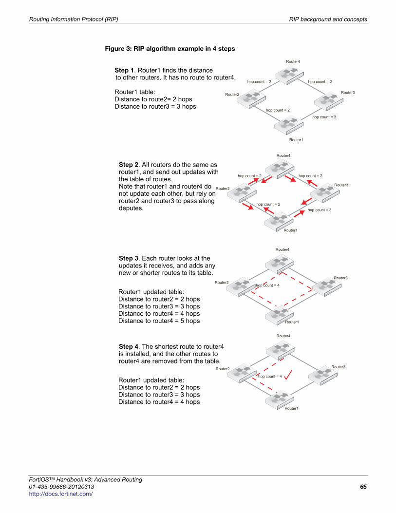
Routing Information Protocol (RIP) RIP background and concepts
F
0
h
Figure 3: RIP algorithm example in 4 steps
Router1
Router2 Router3
Router4
hop count = 2
hop count = 2 hop count = 2
hop count = 3
Step 1. Router1 finds the distance
Router1 table:Distance to route2= 2 hopsDistance to router3 = 3 hops
to other routers. It has no route to router4.
Router1
Router2 Router3
Router4
hop count = 2
hop count = 2 hop count = 2
hop count = 3
Step 2. All routers do the same as router1, and send out updates withthe table of routes.Note that router1 and router4 donot update each other, but rely onrouter2 and router3 to pass alongdeputes.
Router1
Router2 Router3
Router4
hop count = 4
Step 3. Each router looks at the updates it receives, and adds any new or shorter routes to its table.
Router1 updated table:Distance to router2 = 2 hopsDistance to router3 = 3 hopsDistance to router4 = 4 hopsDistance to router4 = 5 hops
Router1
Router2 Router3
Router4
hop count = 4
Step 4. The shortest route to router4
Router1 updated table:Distance to router2 = 2 hopsDistance to router3 = 3 hopsDistance to router4 = 4 hops
is installed, and the other routes torouter4 are removed from the table.
ortiOS™ Handbook v3: Advanced Routing
1-435-99686-20120313 65
ttp://docs.fortinet.com/
RIP background and concepts Routing Information Protocol (RIP)
The good part about the Bellman-Ford algorithm in RIP is that the router only uses the
information it needs from the update. If there are no newer, better routes than the ones
the router already has in its routing table, there is no need to change its routing table. And
no change means no additional update, so less traffic. But even when there is update
traffic, the RIP packets are very small so it takes many updates to affect overall network
bandwidth. For more information about RIP packets, see “RIP packet structure” on
page 67.
The main disadvantage of the Bellman–Ford algorithm in RIP is that it doesn’t take
weightings into consideration. While it is possible to assign different weights to routes in
RIP, doing so severely limits the effective network size by reducing the hop count limit.
Also other dynamic routing protocols can take route qualities, such as reliability or delay,
into consideration to provide not only the physically shortest but also the fastest or more
reliable routes as you choose.
Another disadvantage of the Bellman-Ford algorithm is due to the slow updates passed
from one RIP router to the next. This results in a slow response to changes in the network
topology, which in turn results in more attempts to use routes that are down which
wastes time and network resources.
Passive versus active RIP interfacesNormally the FortiGate unit’s routing table is kept up to date by periodically asking the
neighbors for routes, and sending your routing updates out. This has the downside of
generating a lot of extra traffic for large networks. The solution to this problem is passive
interfaces.
An standard interface that supports RIP is active by default — it both sends and receives
updates by actively communicating with its neighbors. A passive RIP interface does not
send out updates — it just listens to the updates of other routers. This is useful in
reducing network traffic, and if there are redundant routers in the network that would be
sending out essentially the same updates all the time.
The following example shows how to create a passive RIP v2 interface on port1, using
MD5 authentication and a key-chain called passiveRIPv2 that has already been
configured. Note that in the CLI, you enable passive by disabling send-version2-broadcast.
To create a passive RIP interface - web-based manager
1 Go to Router > Dynamic > RIP.
2 Under Interfaces, select Create New.
3 Select port1 as the Interface.
4 Select 2 as both the Send Version and Receive Version.
5 Select MD5 for Authentication.
6 Select the passiveRIPv2 Key-chain.
7 Select Passive Interface.
8 Select OK to accept this configuration, and return to the main RIP display page.
To create a passive RIP v2 interface on port1 using MD5 authentication- CLI
config router ripconfig interfaceedit port1set send-version2-broadcast disableset auth-keychain “passiveRIPv2”
Advanced Routing for FortiOS 4.0 MR3
66 01-435-99686-20120313
http://docs.fortinet.com/
Routing Information Protocol (RIP) RIP background and concepts
F
0
h
set auth-mode md5set receive-version 2set send-version 2
endend
RIP packet structureIt is hard to fully understand a routing protocol without knowing what information is
carried in its packets. Knowing what information is exchanged between routers and how
will help you better understand the RIP protocol, and better configure your network for it.
This section provides information on the contents of RIP 1 and RIP 2 packets.
RIP version 1RIP version 1, or RIP IP packets are 24 bytes in length. The empty areas were left for
future expansion.
The following descriptions summarize the RIP version 1 packet fields.
Command — Indicates whether the packet is a request or a response. The request asks
that a router send all or part of its routing table. The response can be an unsolicited
regular routing update or a reply to a request. Responses contain routing table entries.
Multiple RIP packets are used to convey information from large routing tables.
Version — Specifies the RIP version used. This field can signal different potentially
incompatible versions.
Zero field — This field defaults to zero, and is not used by RFC 1058 RIP.
Address-family identifier (AFI) — Specifies the address family used. RIP is designed to
carry routing information for several different protocols. Each entry has an address-family
identifier to indicate the type of address being specified. The AFI for IP is 2.
IP Address — Specifies the IP address for the entry.
Metric — This is the number of hops or routers traversed along the route on its trip to the
destination. The metric is between 1 and 15 for that number of hops. If the route is
unreachable the metric is 16.
RIP version 2RIP version 2 has more features that RIP 1 and this is reflected in its packets. RIP 2
packets are similar in format to RIP 1, but carry more information. All but one of the
empty zero fields in RIP 1 packets now contain information.
Table 6: RIP IP packets
1-byte
command
1-byte version 2-byte zero
field
2-byte AFI 2-byte zero
field
4-byte IP
address
4-byte zero
field
4-byte zero
field
4-byte metric
Table 7: RIP 2 packets
1-byte
command
1-byte
version
2-byte
unused
2-byte
AFI
2-byte
route
tag
4-byte IP
address
4-byte
subnet
4-byte
next
hop
4-byte
metric
ortiOS™ Handbook v3: Advanced Routing
1-435-99686-20120313 67
ttp://docs.fortinet.com/
Troubleshooting RIP Routing Information Protocol (RIP)
The following descriptions summarize the fields RIP 2 adds to the RIP IP header. The
other fields have been described above for RIP 1.
Unused — Has a value set to zero, and is intended for future use
Route tag — Provides a method for distinguishing between internal routes learned by
RIP and external routes learned from other protocols.
Subnet mask — Contains the subnet mask for the entry. If this field is zero, no subnet
mask has been specified for the entry.
Next hop — Indicates the IP address of the next hop to which packets for the entry
should be forwarded.
Troubleshooting RIP
This section is about troubleshooting RIP. For general troubleshooting information, see
the FortiOS Handbook Troubleshooting chapter.
This section includes:
• Routing Loops
• Split horizon and Poison reverse updates
• Debugging IPv6 on RIPng
Routing Loops
Normally in routing, a path between two addresses is chosen and traffic is routed along
that path from one address to the other. When there is a routing loop, that normal path
doubles back on itself creating a loop. When there are loops, the network has problems.
A routing loop happens when a normally functioning network has an outage, and one or
more routers are offline. When packets encounter this, an alternate route is attempted to
maneuver around the outage. During this phase it is possible for a route to be attempted
that involves going back a hop, and trying a different hop forward. If that hop forward is
blocked by the outage as well, a hop back and possibly the original hop forward may be
selected. You can see if this continues, how it can consume not only network bandwidth
but also many resources on those routers affected. The worst part is this situation will
continue until the network administrator changes the router settings, or the downed
routers come back online.
Routing loops’ effect on the networkIn addition to this “traffic jam” of routed packets, every time the routing table for a router
changes that router sends an update out to all of the RIP routers connected to it. In a
network loop, its possible for a router to change its routes very quickly as it tries and fails
along these new routes. This can quickly result in a flood of updates being sent out,
which can effectively grind the network to a halt until the problem is fixed.
How can you spot a routing loopAny time network traffic slows down, you will be asking yourself if it is a network loop or
not. Often slowdowns are normal, they are not a full stoppage, and normal traffic resumes
in a short period of time.
If the slow down is a full halt of traffic or a major slowdown does not return to normal
quickly, you need to do serious troubleshooting quickly.
Some methods to troubleshoot your outage include:
• Check your logs
Advanced Routing for FortiOS 4.0 MR3
68 01-435-99686-20120313
http://docs.fortinet.com/
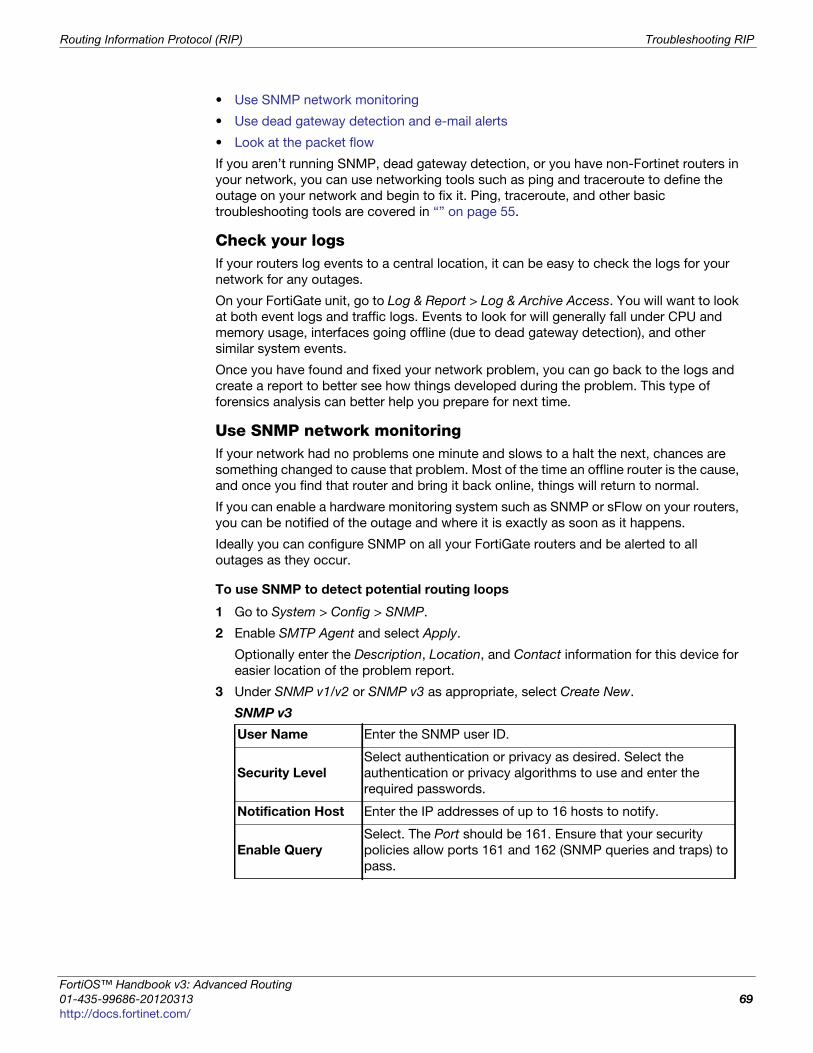
Routing Information Protocol (RIP) Troubleshooting RIP
F
0
h
• Use SNMP network monitoring
• Use dead gateway detection and e-mail alerts
• Look at the packet flow
If you aren’t running SNMP, dead gateway detection, or you have non-Fortinet routers in
your network, you can use networking tools such as ping and traceroute to define the
outage on your network and begin to fix it. Ping, traceroute, and other basic
troubleshooting tools are covered in “” on page 55.
Check your logsIf your routers log events to a central location, it can be easy to check the logs for your
network for any outages.
On your FortiGate unit, go to Log & Report > Log & Archive Access. You will want to look
at both event logs and traffic logs. Events to look for will generally fall under CPU and
memory usage, interfaces going offline (due to dead gateway detection), and other
similar system events.
Once you have found and fixed your network problem, you can go back to the logs and
create a report to better see how things developed during the problem. This type of
forensics analysis can better help you prepare for next time.
Use SNMP network monitoringIf your network had no problems one minute and slows to a halt the next, chances are
something changed to cause that problem. Most of the time an offline router is the cause,
and once you find that router and bring it back online, things will return to normal.
If you can enable a hardware monitoring system such as SNMP or sFlow on your routers,
you can be notified of the outage and where it is exactly as soon as it happens.
Ideally you can configure SNMP on all your FortiGate routers and be alerted to all
outages as they occur.
To use SNMP to detect potential routing loops
1 Go to System > Config > SNMP.
2 Enable SMTP Agent and select Apply.
Optionally enter the Description, Location, and Contact information for this device for
easier location of the problem report.
3 Under SNMP v1/v2 or SNMP v3 as appropriate, select Create New.
SNMP v3
User Name Enter the SNMP user ID.
Security Level
Select authentication or privacy as desired. Select the
authentication or privacy algorithms to use and enter the
required passwords.
Notification Host Enter the IP addresses of up to 16 hosts to notify.
Enable Query
Select. The Port should be 161. Ensure that your security
policies allow ports 161 and 162 (SNMP queries and traps) to
pass.
ortiOS™ Handbook v3: Advanced Routing
1-435-99686-20120313 69
ttp://docs.fortinet.com/
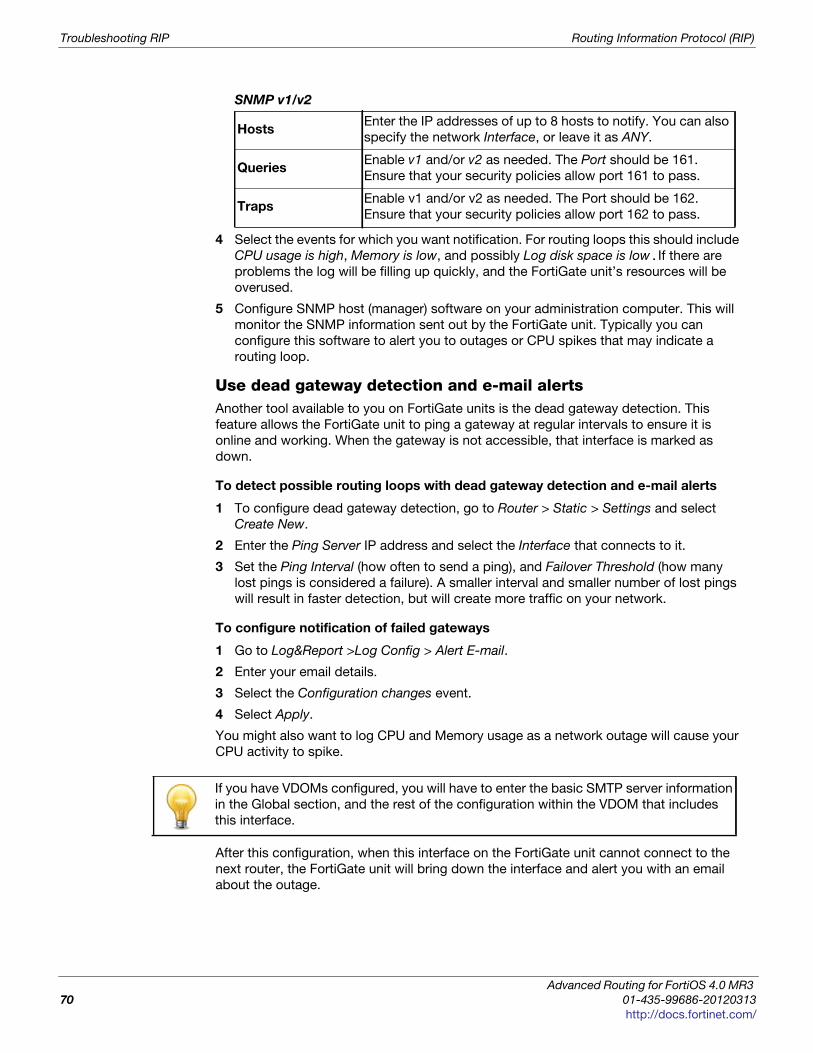
Troubleshooting RIP Routing Information Protocol (RIP)
SNMP v1/v2
4 Select the events for which you want notification. For routing loops this should include
CPU usage is high, Memory is low, and possibly Log disk space is low.If there are
problems the log will be filling up quickly, and the FortiGate unit’s resources will be
overused.
5 Configure SNMP host (manager) software on your administration computer. This will
monitor the SNMP information sent out by the FortiGate unit. Typically you can
configure this software to alert you to outages or CPU spikes that may indicate a
routing loop.
Use dead gateway detection and e-mail alertsAnother tool available to you on FortiGate units is the dead gateway detection. This
feature allows the FortiGate unit to ping a gateway at regular intervals to ensure it is
online and working. When the gateway is not accessible, that interface is marked as
down.
To detect possible routing loops with dead gateway detection and e-mail alerts
1 To configure dead gateway detection, go to Router > Static > Settings and select
Create New.
2 Enter the Ping Server IP address and select the Interface that connects to it.
3 Set the Ping Interval (how often to send a ping), and Failover Threshold (how many
lost pings is considered a failure). A smaller interval and smaller number of lost pings
will result in faster detection, but will create more traffic on your network.
To configure notification of failed gateways
1 Go to Log&Report >Log Config > Alert E-mail.
2 Enter your email details.
3 Select the Configuration changes event.
4 Select Apply.
You might also want to log CPU and Memory usage as a network outage will cause your
CPU activity to spike.
After this configuration, when this interface on the FortiGate unit cannot connect to the
next router, the FortiGate unit will bring down the interface and alert you with an email
about the outage.
HostsEnter the IP addresses of up to 8 hosts to notify. You can also
specify the network Interface, or leave it as ANY.
QueriesEnable v1 and/or v2 as needed. The Port should be 161.
Ensure that your security policies allow port 161 to pass.
TrapsEnable v1 and/or v2 as needed. The Port should be 162.
Ensure that your security policies allow port 162 to pass.
If you have VDOMs configured, you will have to enter the basic SMTP server information
in the Global section, and the rest of the configuration within the VDOM that includes
this interface.
Advanced Routing for FortiOS 4.0 MR3
70 01-435-99686-20120313
http://docs.fortinet.com/
Routing Information Protocol (RIP) Troubleshooting RIP
F
0
h
Look at the packet flowIf you want to see what is happening on your network, look at the packets travelling on
the network. This is same idea as police pulling over a car and asking the driver where
they have been, and what the conditions were like.
The method used in the troubleshooting sections “Debugging IPv6 on RIPng” on page 71
and on debugging the packet flow apply here as well. In this situation, you are looking for
routes that have metrics higher than 15 as that indicates they are unreachable.
Ideally if you debug the flow of the packets, and record the routes that are unreachable,
you can create an accurate picture of the network outage.
Action to take on discovering a routing loopOnce you have mapped the problem on your network, and determined it is in fact a
routing loop there are a number of steps to take in correcting it.
1 Get any offline routers back online. This may be a simple reboot, or you may have to
replace hardware. Often this first step will restore your network to its normal
operation, once the routing tables finish being updated.
2 Change your routing configuration on the edges of the outage. Even if step 1 brought
your network back online, you should consider making changes to improve your
network before the next outage occurs. These changes can include configuring
features like holddowns and triggers for updates, split horizon, and poison reverse
updates.
Split horizon and Poison reverse updates
Split horizon is best explained with an example. You have three routers linked serially,
let’s call them A, B, and C. A is only linked to B, C is only linked to B, and B is linked to
both A and C. To get to C, A must go through B. If the link to C goes down, it is possible
that B will try to use A’s route to get to C. This route is A-B-C, so it will not work. However,
if B tries to use it this begins an endless loop.
This situation is called a split horizon because from B’s point of view the horizon
stretches out in each direction, but in reality it only is on one side.
Poison reverse is the method used to prevent routes from running into split horizon
problems. Poison reverse “poisons” routes away from the destination that use the current
router in their route to the destination. This “poisoned” route is marked as unreachable
for routers that cannot use it. In RIP this means that route is marked with a distance of 16.
Debugging IPv6 on RIPng
The debug commands are very useful to see what is happening on the network at the
packet level. There are a few changes to debugging the packet flow when debugging
IPv6.
The following CLI commands specify both IPv6 and RIP, so only RIPng packets will be
reported. The output from these commands will show you the RIPng traffic on your
FortiGate unit including RECV, SEND, and UPDATE actions.
The addresses are in IPv6 format.
FGT# diagnose debug enableFGT# diagnose ipv6 router rip level infoFGT# diagnose ipv6 router rip all enable
These three commands will:
• turn on debugging in general
ortiOS™ Handbook v3: Advanced Routing
1-435-99686-20120313 71
ttp://docs.fortinet.com/
RIP routing examples Routing Information Protocol (RIP)
• set the debug level to information, a verbose reporting level
• turn on all rip router settings
Part of the information displayed from the debugging is the metric (hop count). If the
metric is 16, then that destination is unreachable since the maximum hop count is 15.
In general, you should see an update announcement, followed by the routing table being
sent out, and a received reply in response.
For more information, see “Testing the IPv6 RIPng information” on page 92
RIP routing examples
The following examples for RIP:
• Simple RIP example
• RIPng — RIP and IPv6
Simple RIP example
This is an example of a typical medium sized network configuration using RIP routing.
Your company has 3 small local networks, one for each department. These networks are
connected by RIP, and then connected to the Internet. Each subnet has more than one
route, for redundancy. There are two central routers that are both connected to the
internet, and to the other networks. If one of those routers goes down, the whole network
can continue to function normally.
The ISP is running RIP, so no importing or exporting routes is required on the side of the
network. However, since the internal networks have static networking running those will
need to be redistributed through the RIP network.
To keep the example simple, there will be no authentication of router traffic.
With RIP properly configured, if the device fails or temporarily goes offline, the routes will
change and traffic will continue to flow. RIP is good for a smaller network due to its lack
of complex configurations.
This section includes the following topics:
• Network layout and assumptions
• General configuration steps
• Configuring the FortiGate units system information
• Configuring other networking devices
• Testing network configuration
Network layout and assumptions
Basic network layoutYour company has 3 departments each with their own network — Sales, R&D, and
Accounting. Each network has routers that are not running RIP as well as FortiGate units
running RIP.
The R&D network has two RIP routers, and each is connected to both other departments
as well as being connected to the Internet through the ISP router. The links to the Internet
are indicated in black.
Advanced Routing for FortiOS 4.0 MR3
72 01-435-99686-20120313
http://docs.fortinet.com/

Routing Information Protocol (RIP) Simple RIP example
F
0
h
The three internal networks do not run RIP. They use static routing because they are small
networks. This means the FortiGate units have to redistribute any static routes they learn
so that the internal networks can communicate with each other.
Where possible in this example, the default values will be used or the most general
settings. This is intended to provide an easier configuration that will require less
troubleshooting.
In this example the routers, networks, interfaces used, and IP addresses are as follows.
Note that the Interfaces that connect Router2 and Router3 also connect to the R&D
network.
Table 8: Rip example network topology
Network Router Interface & Alias IP address
Sales
Router1 port1 (internal) 10.11.101.101
port2 (router2) 10.11.201.101
port3 (router3) 10.11.202.101
R&D
Router2 port1 (internal) 10.12.101.102
port2 (router1) 10.11.201.102
port3 (router4) 10.14.201.102
port4 (ISP) 172.20.120.102
Router3 port1 (internal) 10.12.101.103
port2 (router1) 10.11.201.103
port3 (router4) 10.14.202.103
port4 (ISP) 172.20.120.103
Accounting
Router4 port1 (internal) 10.14.101.104
port2 (router2) 10.14.201.104
port3 (router3) 10.14.202.104
ortiOS™ Handbook v3: Advanced Routing
1-435-99686-20120313 73
ttp://docs.fortinet.com/
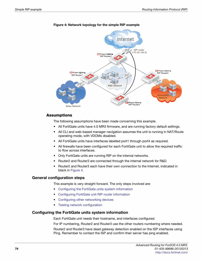
Simple RIP example Routing Information Protocol (RIP)
Figure 4: Network topology for the simple RIP example
AssumptionsThe following assumptions have been made concerning this example.
• All FortiGate units have 4.0 MR3 firmware, and are running factory default settings.
• All CLI and web-based manager navigation assumes the unit is running in NAT/Route
operating mode, with VDOMs disabled.
• All FortiGate units have interfaces labelled port1 through port4 as required.
• All firewalls have been configured for each FortiGate unit to allow the required traffic
to flow across interfaces.
• Only FortiGate units are running RIP on the internal networks.
• Router2 and Router3 are connected through the internal network for R&D.
• Router2 and Router3 each have their own connection to the Internet, indicated in
black in Figure 4.
General configuration steps
This example is very straight forward. The only steps involved are:
• Configuring the FortiGate units system information
• Configuring FortiGate unit RIP router information
• Configuring other networking devices
• Testing network configuration
Configuring the FortiGate units system information
Each FortiGate unit needs their hostname, and interfaces configured.
For IP numbering, Router2 and Router3 use the other routers numbering where needed.
Router2 and Router3 have dead gateway detection enabled on the ISP interfaces using
Ping. Remember to contact the ISP and confirm their server has ping enabled.
ISP router (172.20.120.5)
RIP Router1
RIP Router2
Sales Network
RIP Router4
AccountingNetwork
R&D Network
RIP Router3RI
uter1RIP
uter2
Advanced Routing for FortiOS 4.0 MR3
74 01-435-99686-20120313
http://docs.fortinet.com/
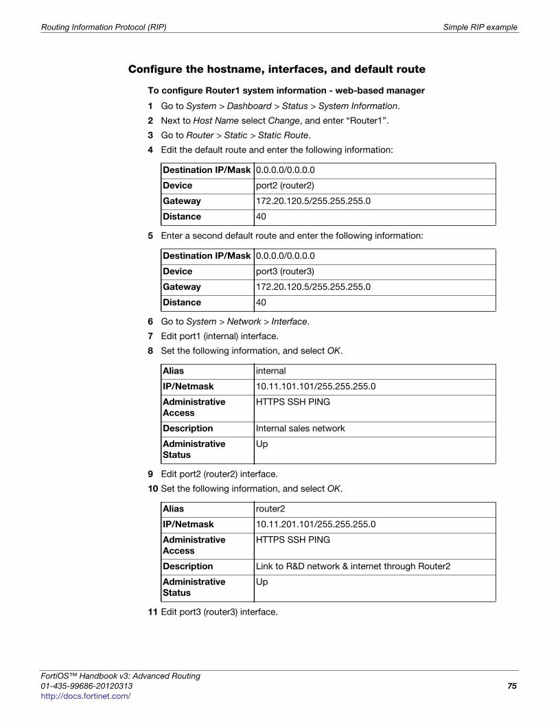
Routing Information Protocol (RIP) Simple RIP example
F
0
h
Configure the hostname, interfaces, and default route
To configure Router1 system information - web-based manager
1 Go to System > Dashboard > Status > System Information.
2 Next to Host Name select Change, and enter “Router1”.
3 Go to Router > Static > Static Route.
4 Edit the default route and enter the following information:
5 Enter a second default route and enter the following information:
6 Go to System > Network > Interface.
7 Edit port1 (internal) interface.
8 Set the following information, and select OK.
9 Edit port2 (router2) interface.
10 Set the following information, and select OK.
11 Edit port3 (router3) interface.
Destination IP/Mask 0.0.0.0/0.0.0.0
Device port2 (router2)
Gateway 172.20.120.5/255.255.255.0
Distance 40
Destination IP/Mask 0.0.0.0/0.0.0.0
Device port3 (router3)
Gateway 172.20.120.5/255.255.255.0
Distance 40
Alias internal
IP/Netmask 10.11.101.101/255.255.255.0
Administrative
Access
HTTPS SSH PING
Description Internal sales network
Administrative
Status
Up
Alias router2
IP/Netmask 10.11.201.101/255.255.255.0
Administrative
Access
HTTPS SSH PING
Description Link to R&D network & internet through Router2
Administrative
Status
Up
ortiOS™ Handbook v3: Advanced Routing
1-435-99686-20120313 75
ttp://docs.fortinet.com/
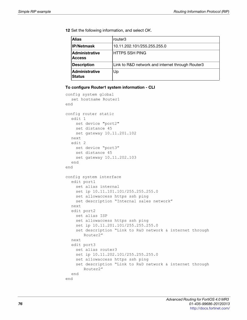
Simple RIP example Routing Information Protocol (RIP)
12 Set the following information, and select OK.
To configure Router1 system information - CLI
config system globalset hostname Router1
end
config router staticedit 1set device "port2"set distance 45set gateway 10.11.201.102
nextedit 2set device “port3”set distance 45set gateway 10.11.202.103
endend
config system interfaceedit port1set alias internalset ip 10.11.101.101/255.255.255.0set allowaccess https ssh pingset description “Internal sales network”
nextedit port2set alias ISPset allowaccess https ssh pingset ip 10.11.201.101/255.255.255.0set description “Link to R&D network & internet through
Router2”nextedit port3set alias router3set ip 10.11.202.101/255.255.255.0set allowaccess https ssh pingset description “Link to R&D network & internet through
Router2”end
end
Alias router3
IP/Netmask 10.11.202.101/255.255.255.0
Administrative
Access
HTTPS SSH PING
Description Link to R&D network and internet through Router3
Administrative
Status
Up
Advanced Routing for FortiOS 4.0 MR3
76 01-435-99686-20120313
http://docs.fortinet.com/
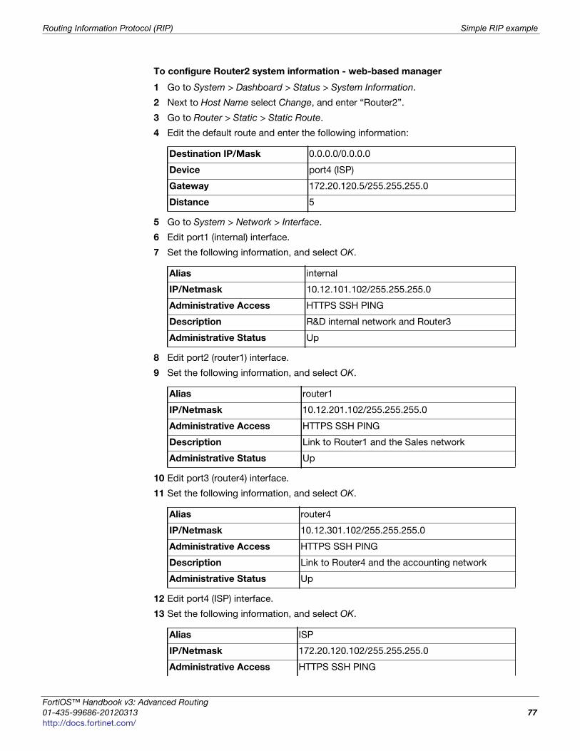
Routing Information Protocol (RIP) Simple RIP example
F
0
h
To configure Router2 system information - web-based manager
1 Go to System > Dashboard > Status > System Information.
2 Next to Host Name select Change, and enter “Router2”.
3 Go to Router > Static > Static Route.
4 Edit the default route and enter the following information:
5 Go to System > Network > Interface.
6 Edit port1 (internal) interface.
7 Set the following information, and select OK.
8 Edit port2 (router1) interface.
9 Set the following information, and select OK.
10 Edit port3 (router4) interface.
11 Set the following information, and select OK.
12 Edit port4 (ISP) interface.
13 Set the following information, and select OK.
Destination IP/Mask 0.0.0.0/0.0.0.0
Device port4 (ISP)
Gateway 172.20.120.5/255.255.255.0
Distance 5
Alias internal
IP/Netmask 10.12.101.102/255.255.255.0
Administrative Access HTTPS SSH PING
Description R&D internal network and Router3
Administrative Status Up
Alias router1
IP/Netmask 10.12.201.102/255.255.255.0
Administrative Access HTTPS SSH PING
Description Link to Router1 and the Sales network
Administrative Status Up
Alias router4
IP/Netmask 10.12.301.102/255.255.255.0
Administrative Access HTTPS SSH PING
Description Link to Router4 and the accounting network
Administrative Status Up
Alias ISP
IP/Netmask 172.20.120.102/255.255.255.0
Administrative Access HTTPS SSH PING
ortiOS™ Handbook v3: Advanced Routing
1-435-99686-20120313 77
ttp://docs.fortinet.com/
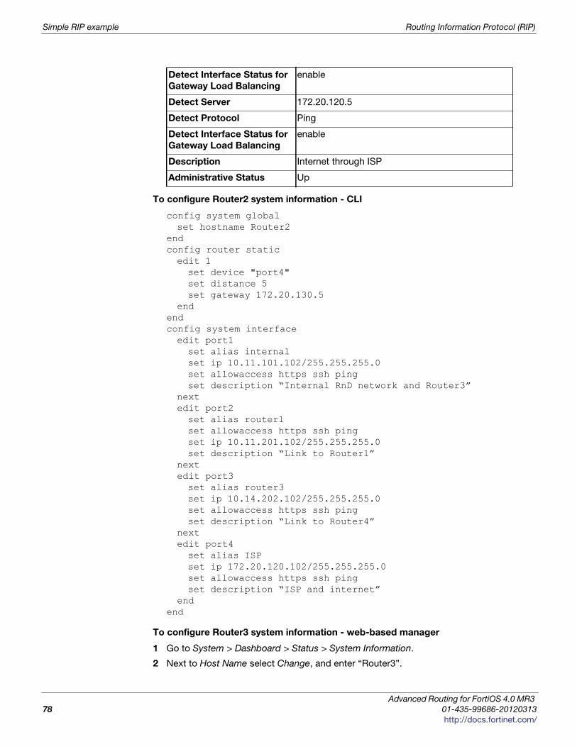
Simple RIP example Routing Information Protocol (RIP)
To configure Router2 system information - CLI
config system globalset hostname Router2
endconfig router staticedit 1set device "port4"set distance 5set gateway 172.20.130.5
endendconfig system interfaceedit port1set alias internalset ip 10.11.101.102/255.255.255.0set allowaccess https ssh pingset description “Internal RnD network and Router3”
nextedit port2set alias router1set allowaccess https ssh pingset ip 10.11.201.102/255.255.255.0set description “Link to Router1”
nextedit port3set alias router3set ip 10.14.202.102/255.255.255.0set allowaccess https ssh pingset description “Link to Router4”
nextedit port4set alias ISPset ip 172.20.120.102/255.255.255.0set allowaccess https ssh pingset description “ISP and internet”
endend
To configure Router3 system information - web-based manager
1 Go to System > Dashboard > Status > System Information.
2 Next to Host Name select Change, and enter “Router3”.
Detect Interface Status for
Gateway Load Balancing
enable
Detect Server 172.20.120.5
Detect Protocol Ping
Detect Interface Status for
Gateway Load Balancing
enable
Description Internet through ISP
Administrative Status Up
Advanced Routing for FortiOS 4.0 MR3
78 01-435-99686-20120313
http://docs.fortinet.com/
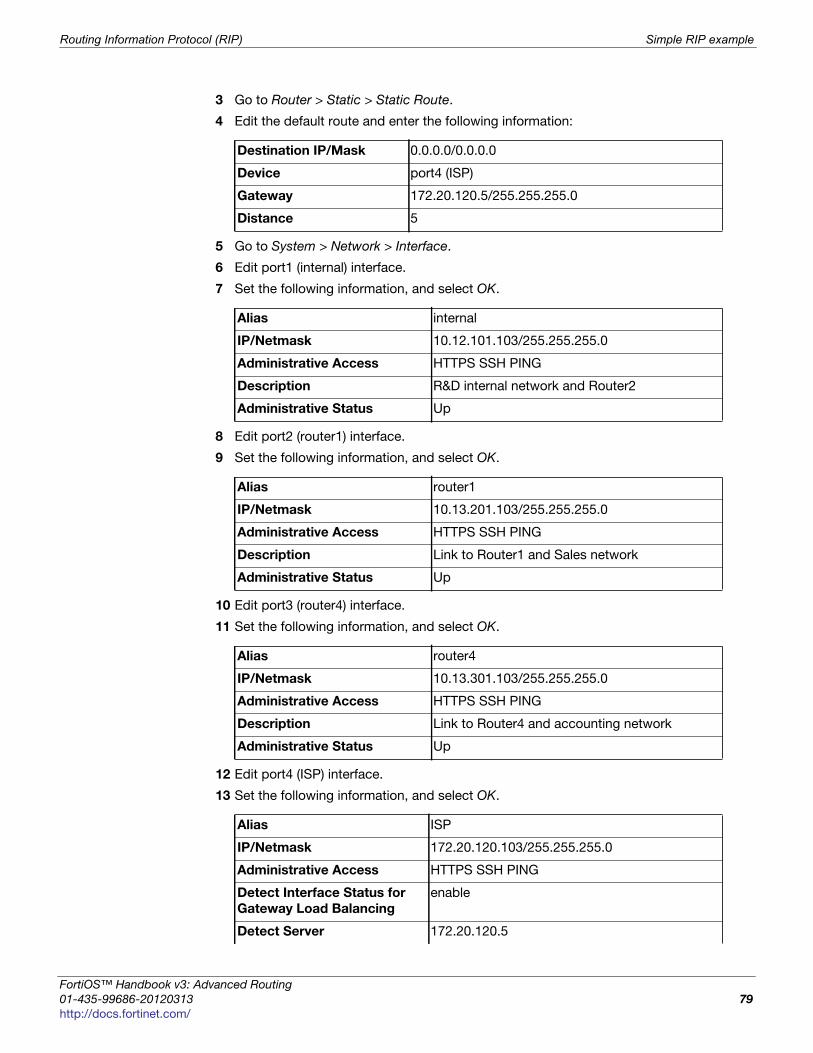
Routing Information Protocol (RIP) Simple RIP example
F
0
h
3 Go to Router > Static > Static Route.
4 Edit the default route and enter the following information:
5 Go to System > Network > Interface.
6 Edit port1 (internal) interface.
7 Set the following information, and select OK.
8 Edit port2 (router1) interface.
9 Set the following information, and select OK.
10 Edit port3 (router4) interface.
11 Set the following information, and select OK.
12 Edit port4 (ISP) interface.
13 Set the following information, and select OK.
Destination IP/Mask 0.0.0.0/0.0.0.0
Device port4 (ISP)
Gateway 172.20.120.5/255.255.255.0
Distance 5
Alias internal
IP/Netmask 10.12.101.103/255.255.255.0
Administrative Access HTTPS SSH PING
Description R&D internal network and Router2
Administrative Status Up
Alias router1
IP/Netmask 10.13.201.103/255.255.255.0
Administrative Access HTTPS SSH PING
Description Link to Router1 and Sales network
Administrative Status Up
Alias router4
IP/Netmask 10.13.301.103/255.255.255.0
Administrative Access HTTPS SSH PING
Description Link to Router4 and accounting network
Administrative Status Up
Alias ISP
IP/Netmask 172.20.120.103/255.255.255.0
Administrative Access HTTPS SSH PING
Detect Interface Status for
Gateway Load Balancing
enable
Detect Server 172.20.120.5
ortiOS™ Handbook v3: Advanced Routing
1-435-99686-20120313 79
ttp://docs.fortinet.com/
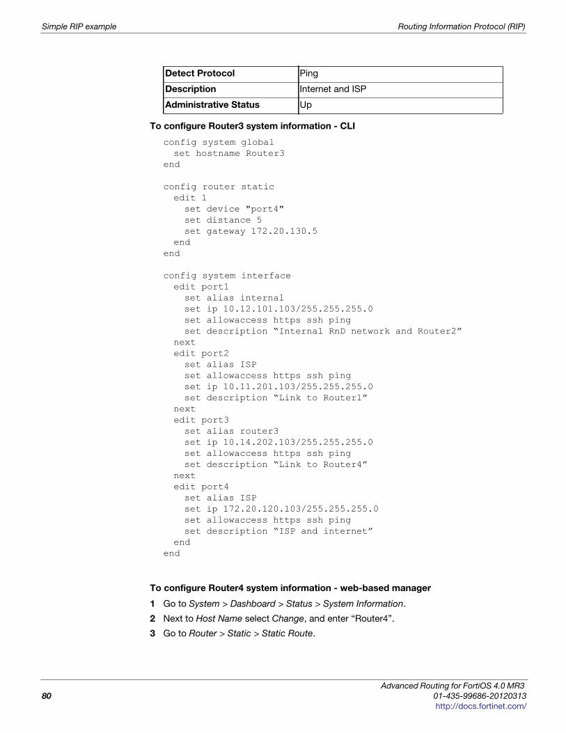
Simple RIP example Routing Information Protocol (RIP)
To configure Router3 system information - CLI
config system globalset hostname Router3
end
config router staticedit 1set device "port4"set distance 5set gateway 172.20.130.5
endend
config system interfaceedit port1set alias internalset ip 10.12.101.103/255.255.255.0set allowaccess https ssh pingset description “Internal RnD network and Router2”
nextedit port2set alias ISPset allowaccess https ssh pingset ip 10.11.201.103/255.255.255.0set description “Link to Router1”
nextedit port3set alias router3set ip 10.14.202.103/255.255.255.0set allowaccess https ssh pingset description “Link to Router4”
nextedit port4set alias ISPset ip 172.20.120.103/255.255.255.0set allowaccess https ssh pingset description “ISP and internet”
endend
To configure Router4 system information - web-based manager
1 Go to System > Dashboard > Status > System Information.
2 Next to Host Name select Change, and enter “Router4”.
3 Go to Router > Static > Static Route.
Detect Protocol Ping
Description Internet and ISP
Administrative Status Up
Advanced Routing for FortiOS 4.0 MR3
80 01-435-99686-20120313
http://docs.fortinet.com/
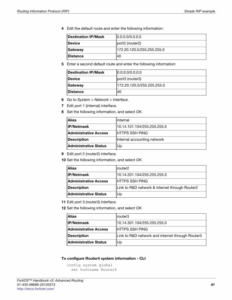
Routing Information Protocol (RIP) Simple RIP example
F
0
h
4 Edit the default route and enter the following information:
5 Enter a second default route and enter the following information:
6 Go to System > Network > Interface.
7 Edit port 1 (internal) interface.
8 Set the following information, and select OK.
9 Edit port 2 (router2) interface.
10 Set the following information, and select OK.
11 Edit port 3 (router3) interface.
12 Set the following information, and select OK.
To configure Router4 system information - CLI
config system globalset hostname Router4
Destination IP/Mask 0.0.0.0/0.0.0.0
Device port2 (router2)
Gateway 172.20.120.5/255.255.255.0
Distance 40
Destination IP/Mask 0.0.0.0/0.0.0.0
Device port3 (router3)
Gateway 172.20.120.5/255.255.255.0
Distance 40
Alias internal
IP/Netmask 10.14.101.104/255.255.255.0
Administrative Access HTTPS SSH PING
Description Internal accounting network
Administrative Status Up
Alias router2
IP/Netmask 10.14.201.104/255.255.255.0
Administrative Access HTTPS SSH PING
Description Link to R&D network & internet through Router2
Administrative Status Up
Alias router3
IP/Netmask 10.14.301.104/255.255.255.0
Administrative Access HTTPS SSH PING
Description Link to R&D network and internet through Router3
Administrative Status Up
ortiOS™ Handbook v3: Advanced Routing
1-435-99686-20120313 81
ttp://docs.fortinet.com/
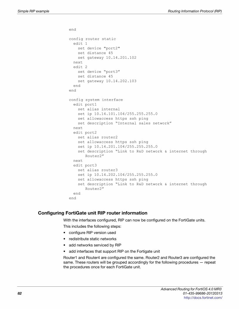
Simple RIP example Routing Information Protocol (RIP)
end
config router staticedit 1set device "port2"set distance 45set gateway 10.14.201.102
nextedit 2set device “port3”set distance 45set gateway 10.14.202.103
endend
config system interfaceedit port1set alias internalset ip 10.14.101.104/255.255.255.0set allowaccess https ssh pingset description “Internal sales network”
nextedit port2set alias router2set allowaccess https ssh pingset ip 10.14.201.104/255.255.255.0set description “Link to R&D network & internet through
Router2”nextedit port3set alias router3set ip 10.14.202.104/255.255.255.0set allowaccess https ssh pingset description “Link to R&D network & internet through
Router2”end
end
Configuring FortiGate unit RIP router information
With the interfaces configured, RIP can now be configured on the FortiGate units.
This includes the following steps:
• configure RIP version used
• redistribute static networks
• add networks serviced by RIP
• add interfaces that support RIP on the Fortigate unit
Router1 and Router4 are configured the same. Router2 and Router3 are configured the
same. These routers will be grouped accordingly for the following procedures — repeat
the procedures once for each FortiGate unit.
Advanced Routing for FortiOS 4.0 MR3
82 01-435-99686-20120313
http://docs.fortinet.com/
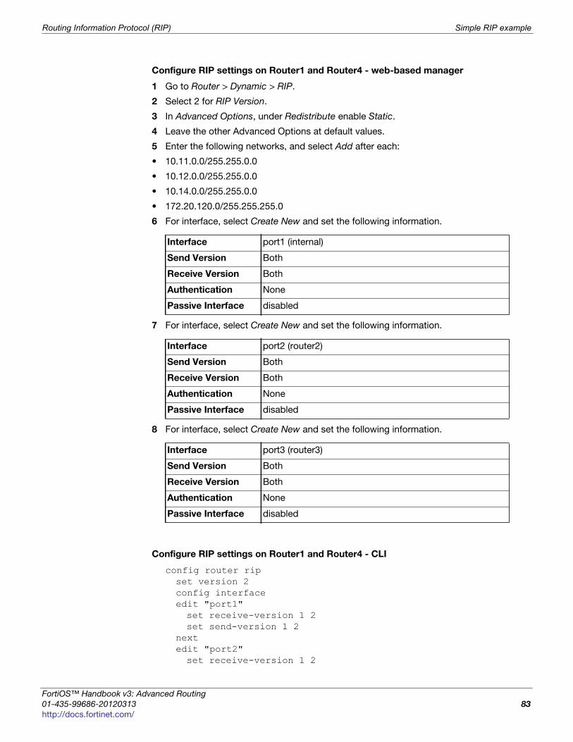
Routing Information Protocol (RIP) Simple RIP example
F
0
h
Configure RIP settings on Router1 and Router4 - web-based manager
1 Go to Router > Dynamic > RIP.
2 Select 2 for RIP Version.
3 In Advanced Options, under Redistribute enable Static.
4 Leave the other Advanced Options at default values.
5 Enter the following networks, and select Add after each:
• 10.11.0.0/255.255.0.0
• 10.12.0.0/255.255.0.0
• 10.14.0.0/255.255.0.0
• 172.20.120.0/255.255.255.0
6 For interface, select Create New and set the following information.
7 For interface, select Create New and set the following information.
8 For interface, select Create New and set the following information.
Configure RIP settings on Router1 and Router4 - CLI
config router ripset version 2config interfaceedit "port1"set receive-version 1 2set send-version 1 2
nextedit "port2"set receive-version 1 2
Interface port1 (internal)
Send Version Both
Receive Version Both
Authentication None
Passive Interface disabled
Interface port2 (router2)
Send Version Both
Receive Version Both
Authentication None
Passive Interface disabled
Interface port3 (router3)
Send Version Both
Receive Version Both
Authentication None
Passive Interface disabled
ortiOS™ Handbook v3: Advanced Routing
1-435-99686-20120313 83
ttp://docs.fortinet.com/
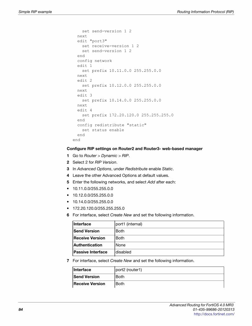
Simple RIP example Routing Information Protocol (RIP)
set send-version 1 2nextedit "port3"set receive-version 1 2set send-version 1 2
endconfig networkedit 1set prefix 10.11.0.0 255.255.0.0
nextedit 2set prefix 10.12.0.0 255.255.0.0
nextedit 3set prefix 10.14.0.0 255.255.0.0
nextedit 4set prefix 172.20.120.0 255.255.255.0
endconfig redistribute "static"set status enable
endend
Configure RIP settings on Router2 and Router3- web-based manager
1 Go to Router > Dynamic > RIP.
2 Select 2 for RIP Version.
3 In Advanced Options, under Redistribute enable Static.
4 Leave the other Advanced Options at default values.
5 Enter the following networks, and select Add after each:
• 10.11.0.0/255.255.0.0
• 10.12.0.0/255.255.0.0
• 10.14.0.0/255.255.0.0
• 172.20.120.0/255.255.255.0
6 For interface, select Create New and set the following information.
7 For interface, select Create New and set the following information.
Interface port1 (internal)
Send Version Both
Receive Version Both
Authentication None
Passive Interface disabled
Interface port2 (router1)
Send Version Both
Receive Version Both
Advanced Routing for FortiOS 4.0 MR3
84 01-435-99686-20120313
http://docs.fortinet.com/
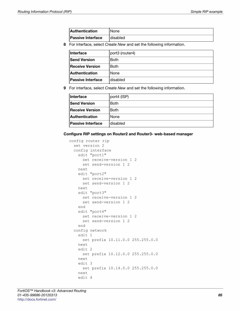
Routing Information Protocol (RIP) Simple RIP example
F
0
h
8 For interface, select Create New and set the following information.
9 For interface, select Create New and set the following information.
Configure RIP settings on Router2 and Router3- web-based manager
config router ripset version 2config interfaceedit "port1"set receive-version 1 2set send-version 1 2
nextedit "port2"set receive-version 1 2set send-version 1 2
nextedit "port3"set receive-version 1 2set send-version 1 2
endedit "port4"set receive-version 1 2set send-version 1 2
endconfig networkedit 1set prefix 10.11.0.0 255.255.0.0
nextedit 2set prefix 10.12.0.0 255.255.0.0
nextedit 3set prefix 10.14.0.0 255.255.0.0
nextedit 4
Authentication None
Passive Interface disabled
Interface port3 (router4)
Send Version Both
Receive Version Both
Authentication None
Passive Interface disabled
Interface port4 (ISP)
Send Version Both
Receive Version Both
Authentication None
Passive Interface disabled
ortiOS™ Handbook v3: Advanced Routing
1-435-99686-20120313 85
ttp://docs.fortinet.com/
RIPng — RIP and IPv6 Routing Information Protocol (RIP)
set prefix 172.20.120.0 255.255.255.0end
config redistribute "static"set status enable
endend
Configuring other networking devices
In this example there are two groups of other devices on the the network — internal
devices, and the ISP.
The first is the internal network devices on the Sales, R&D, and Accounting networks.
This includes simple static routers, computers, printers and other network devices. Once
the FortiGate units are configured, the internal static routers need to be configured using
the internal network IP addresses. Otherwise there should be no configuration required.
The second group of devices is the ISP. This consists of the RIP router the FortiGate
routers 2 and 3 connect to. You need to contact your ISP and ensure they have your
information for your network such as the IP addresses of the connecting RIP routers,
what version of RIP your network supports, and what authentication (if any) is used.
Testing network configuration
Once the network has been configured, you need to test that it works as expected.
The two series of tests you need to run are to test the internal networks can communicate
with each other, and that the internal networks can reach the internet.
Use ping, traceroute, and other networking tools to run these tests.
If you encounter problems, for troubleshooting help consult “Troubleshooting RIP” on
page 68, and the general “” on page 55.
RIPng — RIP and IPv6
RIP next generation, or RIPng, is the version of RIP that supports IPv6.
This is an example of a typical small network configuration using RIPng routing.
Your internal R&D network is working on a project for a large international telecom
company that uses IPv6. For this reason, you have to run IPv6 on your internal network
and you have decided to use only IPv6 addresses.
Your network has two FortiGate units running the RIPng dynamic routing protocol. Both
FortiGate units are connected to the ISP router and the internal network. This
configuration provides some redundancy for the R&D internal network enabling it to
reach the internet at all times.
This section includes the following topics:
• Network layout and assumptions
• General configuration steps
• Configuring the FortiGate units system information
• Configuring other networking devices
• Testing network configuration
Advanced Routing for FortiOS 4.0 MR3
86 01-435-99686-20120313
http://docs.fortinet.com/
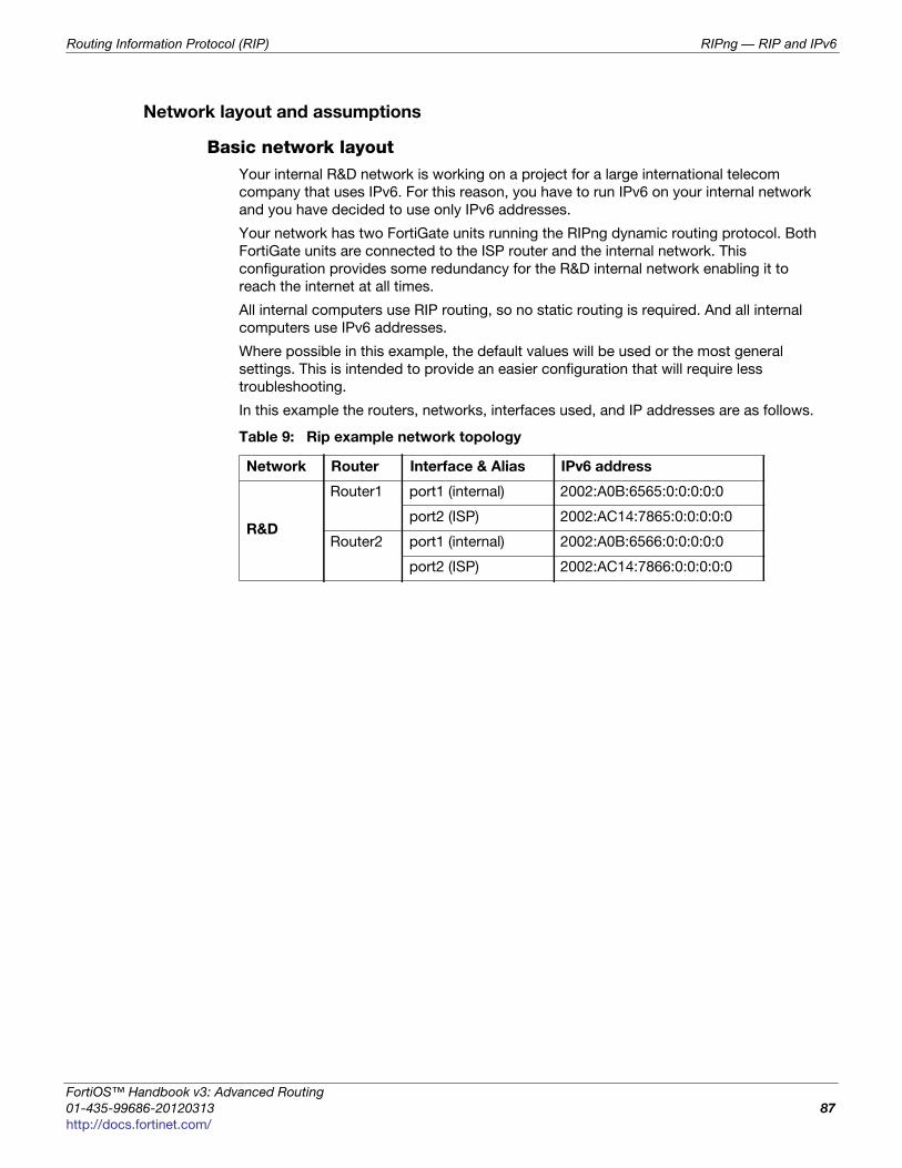
Routing Information Protocol (RIP) RIPng — RIP and IPv6
F
0
h
Network layout and assumptions
Basic network layoutYour internal R&D network is working on a project for a large international telecom
company that uses IPv6. For this reason, you have to run IPv6 on your internal network
and you have decided to use only IPv6 addresses.
Your network has two FortiGate units running the RIPng dynamic routing protocol. Both
FortiGate units are connected to the ISP router and the internal network. This
configuration provides some redundancy for the R&D internal network enabling it to
reach the internet at all times.
All internal computers use RIP routing, so no static routing is required. And all internal
computers use IPv6 addresses.
Where possible in this example, the default values will be used or the most general
settings. This is intended to provide an easier configuration that will require less
troubleshooting.
In this example the routers, networks, interfaces used, and IP addresses are as follows.
Table 9: Rip example network topology
Network Router Interface & Alias IPv6 address
R&D
Router1 port1 (internal) 2002:A0B:6565:0:0:0:0:0
port2 (ISP) 2002:AC14:7865:0:0:0:0:0
Router2 port1 (internal) 2002:A0B:6566:0:0:0:0:0
port2 (ISP) 2002:AC14:7866:0:0:0:0:0
ortiOS™ Handbook v3: Advanced Routing
1-435-99686-20120313 87
ttp://docs.fortinet.com/
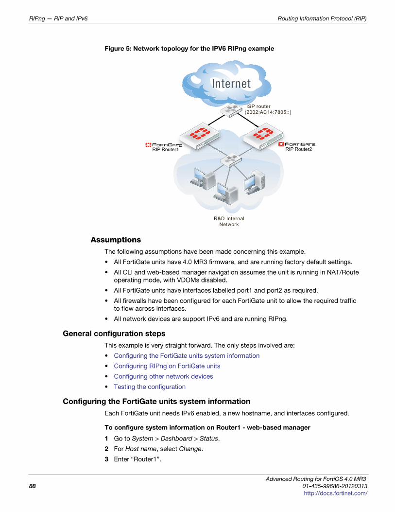
RIPng — RIP and IPv6 Routing Information Protocol (RIP)
Figure 5: Network topology for the IPV6 RIPng example
AssumptionsThe following assumptions have been made concerning this example.
• All FortiGate units have 4.0 MR3 firmware, and are running factory default settings.
• All CLI and web-based manager navigation assumes the unit is running in NAT/Route
operating mode, with VDOMs disabled.
• All FortiGate units have interfaces labelled port1 and port2 as required.
• All firewalls have been configured for each FortiGate unit to allow the required traffic
to flow across interfaces.
• All network devices are support IPv6 and are running RIPng.
General configuration steps
This example is very straight forward. The only steps involved are:
• Configuring the FortiGate units system information
• Configuring RIPng on FortiGate units
• Configuring other network devices
• Testing the configuration
Configuring the FortiGate units system information
Each FortiGate unit needs IPv6 enabled, a new hostname, and interfaces configured.
To configure system information on Router1 - web-based manager
1 Go to System > Dashboard > Status.
2 For Host name, select Change.
3 Enter “Router1”.
RIP Router2
R&D InternalNetwork
RIP Router1
ISP router (2002:AC14:7805::)
r1 R
Advanced Routing for FortiOS 4.0 MR3
88 01-435-99686-20120313
http://docs.fortinet.com/
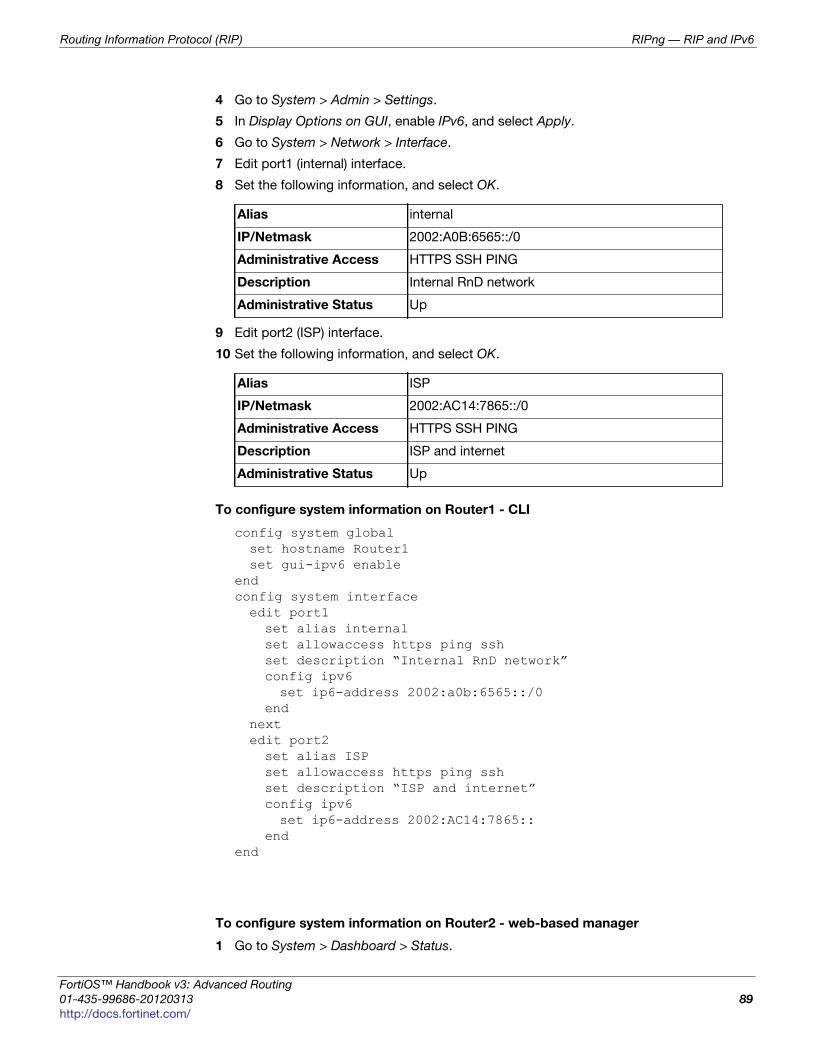
Routing Information Protocol (RIP) RIPng — RIP and IPv6
F
0
h
4 Go to System > Admin > Settings.
5 In Display Options on GUI, enable IPv6, and select Apply.
6 Go to System > Network > Interface.
7 Edit port1 (internal) interface.
8 Set the following information, and select OK.
9 Edit port2 (ISP) interface.
10 Set the following information, and select OK.
To configure system information on Router1 - CLI
config system globalset hostname Router1set gui-ipv6 enable
endconfig system interfaceedit port1set alias internalset allowaccess https ping sshset description “Internal RnD network”config ipv6set ip6-address 2002:a0b:6565::/0
endnextedit port2set alias ISPset allowaccess https ping sshset description “ISP and internet”config ipv6set ip6-address 2002:AC14:7865::
endend
To configure system information on Router2 - web-based manager
1 Go to System > Dashboard > Status.
Alias internal
IP/Netmask 2002:A0B:6565::/0
Administrative Access HTTPS SSH PING
Description Internal RnD network
Administrative Status Up
Alias ISP
IP/Netmask 2002:AC14:7865::/0
Administrative Access HTTPS SSH PING
Description ISP and internet
Administrative Status Up
ortiOS™ Handbook v3: Advanced Routing
1-435-99686-20120313 89
ttp://docs.fortinet.com/
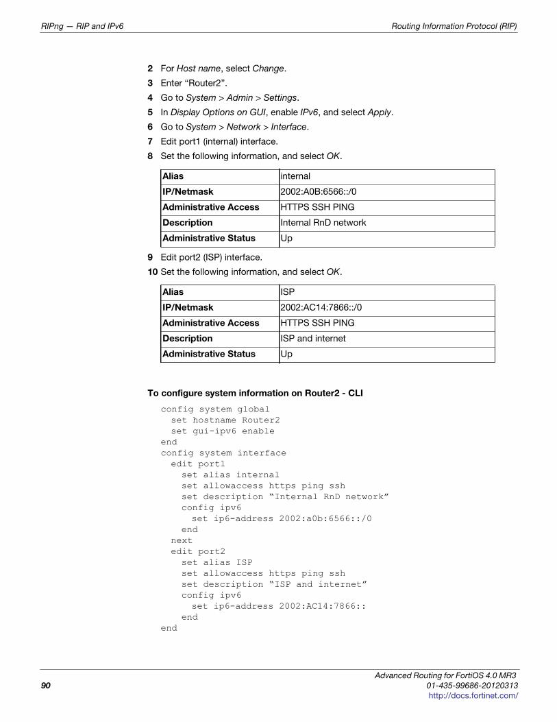
RIPng — RIP and IPv6 Routing Information Protocol (RIP)
2 For Host name, select Change.
3 Enter “Router2”.
4 Go to System > Admin > Settings.
5 In Display Options on GUI, enable IPv6, and select Apply.
6 Go to System > Network > Interface.
7 Edit port1 (internal) interface.
8 Set the following information, and select OK.
9 Edit port2 (ISP) interface.
10 Set the following information, and select OK.
To configure system information on Router2 - CLI
config system globalset hostname Router2set gui-ipv6 enable
endconfig system interfaceedit port1set alias internalset allowaccess https ping sshset description “Internal RnD network”config ipv6set ip6-address 2002:a0b:6566::/0
endnextedit port2set alias ISPset allowaccess https ping sshset description “ISP and internet”config ipv6set ip6-address 2002:AC14:7866::
endend
Alias internal
IP/Netmask 2002:A0B:6566::/0
Administrative Access HTTPS SSH PING
Description Internal RnD network
Administrative Status Up
Alias ISP
IP/Netmask 2002:AC14:7866::/0
Administrative Access HTTPS SSH PING
Description ISP and internet
Administrative Status Up
Advanced Routing for FortiOS 4.0 MR3
90 01-435-99686-20120313
http://docs.fortinet.com/
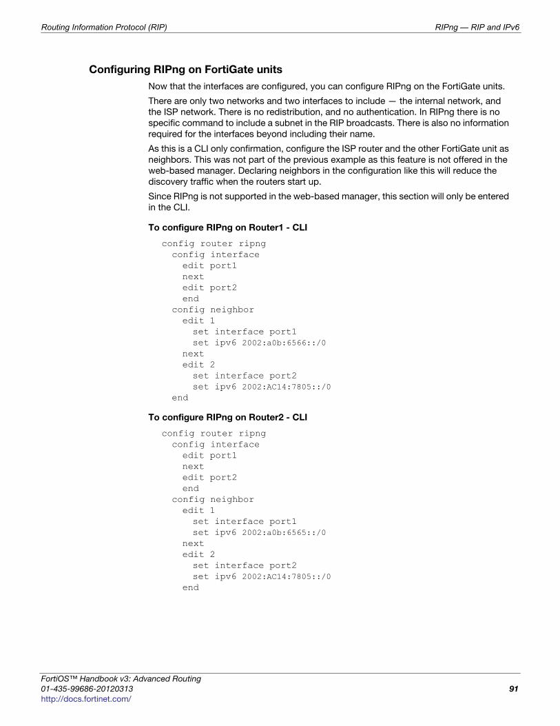
Routing Information Protocol (RIP) RIPng — RIP and IPv6
F
0
h
Configuring RIPng on FortiGate units
Now that the interfaces are configured, you can configure RIPng on the FortiGate units.
There are only two networks and two interfaces to include — the internal network, and
the ISP network. There is no redistribution, and no authentication. In RIPng there is no
specific command to include a subnet in the RIP broadcasts. There is also no information
required for the interfaces beyond including their name.
As this is a CLI only confirmation, configure the ISP router and the other FortiGate unit as
neighbors. This was not part of the previous example as this feature is not offered in the
web-based manager. Declaring neighbors in the configuration like this will reduce the
discovery traffic when the routers start up.
Since RIPng is not supported in the web-based manager, this section will only be entered
in the CLI.
To configure RIPng on Router1 - CLI
config router ripngconfig interfaceedit port1nextedit port2end
config neighboredit 1set interface port1set ipv6 2002:a0b:6566::/0
nextedit 2set interface port2set ipv6 2002:AC14:7805::/0
end
To configure RIPng on Router2 - CLI
config router ripngconfig interfaceedit port1nextedit port2end
config neighboredit 1set interface port1set ipv6 2002:a0b:6565::/0
nextedit 2set interface port2set ipv6 2002:AC14:7805::/0
end
ortiOS™ Handbook v3: Advanced Routing
1-435-99686-20120313 91
ttp://docs.fortinet.com/
RIPng — RIP and IPv6 Routing Information Protocol (RIP)
Configuring other network devices
The other devices on the internal network all support IPv6, and are running RIPng where
applicable. They only need to know the internal interface network addresses of the
FortiGate units.
The ISP routers need to know the FortiGate unit information such as IPv6 addresses.
Testing the configuration
In addition to normal testing of your network configuration, you must also test the IPv6
part of this example.
For troubleshooting problems with your network, see the FortiOS Handbook
Troubleshooting chapter.
For troubleshooting problems with RIP, see“Troubleshooting RIP” on page 68.
Use the following section for testing and troubleshooting RIPng.
Testing the IPv6 RIPng informationThere are some commands to use when checking that your RIPng information is correct
on your network. These are useful to check on your RIPng FortiGate units on your
network. Comparing the output between devices will help you understand your network
better, and also track down any problems.
FGT# diagnose ipv6 address list
View the local scope IPv6 addresses used as next-hops by RIPng on the FortiGate
unit.
FGT# diagnose ipv6 route list
View ipv6 addresses that are installed in the routing table.
FGT# get router info6 routing-table
View the routing table. This information is almost the same as the previous command
(diagnose ipv6 route list) however it is presented in an easier to read format.
FGT# get router info6 rip interface external
View brief output on the RIP information for the interface listed. The information
includes if the interface is up or down, what routing protocol is being used, and
whether passive interface or split horizon are enabled.
FGT# get router info6 neighbor-cache list
View the IPv6/MAC address mapping. This also displays the interface index and name
associated with the address.
Advanced Routing for FortiOS 4.0 MR3
92 01-435-99686-20120313
http://docs.fortinet.com/
F o r t i O S H a n d b o o k
F
0
h
Border Gateway Protocol (BGP)This section describes Border Gateway Protocol (BGP).
The following topics are included in this section:
• BGP background and concepts
• Troubleshooting BGP
• BGP routing examples
BGP background and concepts
The border gateway protocol contains two distinct subsets — internal BGP (iBGP) and
external BGP (eBGP). iBGP is intended for use within your own networks. eBGP is used
to connect many different networks together, and is the main routing protocol for the
Internet backbone. FortiGate units support iBGP, and eBGP only for communities.
The following topics are included in this section:
• Background
• Parts and terminology of BGP
• How BGP works
Background
BGP was first used in 1989. The current version, BGP-4, was released in 1995 and is
defined in RFC 1771. That RFC has since been replaced by the more recent RFC 4271.
The main benefits of BGP-4 are classless inter-domain routing, and aggregate routes.
BGP is the only routing protocol to use TCP for a transport protocol. Other routing
protocols use UDP.
BGP makes routing decisions based on path, network policies and rulesets instead of the
hop-count metric as RIP does, or cost-factor metrics as OSPF does.
BGP-4+ supports IPv6. It was introduced in RFC 2858 and RFC 2545. BGP-4+ also
supports
BGP is the routing protocol used on the Internet. It was designed to replace the old
Exterior Gateway Protocol (EGP) which had been around since 1982, and was very
limited. In doing so, BGP enabled more networks to take part in the Internet backbone to
effectively decentralize it and make the Internet more robust, and less dependent on a
single ISP or backbone network.
Parts and terminology of BGP
In a BGP network, there are some terms that need to be explained before going ahead.
Some parts of BGP are not explained here as they are common to other dynamic routing
protocols as well. For more information on parts of BGP that are not listed here, see
“Dynamic routing terminology” on page 50.
The following topics are included in this section:
ortiOS™ Handbook v3: Advanced Routing
1-433-98043-20120608 93
ttp://docs.fortinet.com/
Parts and terminology of BGP Border Gateway Protocol (BGP)
• BGP and IPv6
• Roles of routers in BGP networks
• Network Layer Reachability Information (NLRI)
• BGP attributes
• Confederations
BGP and IPv6
FortiGate units support IPv6 over BGP using the same config router bgp command
as IPv4, but different subcommands.
The main CLI keywords have IPv6 equivalents that are identified by the “6” on the end of
the keyword, such as with config netowrk6 or set allowas-in6. For more
information about IPv6 BGP keywords, see the FortiGate CLI Reference.
IPv6 BGP commands include:
config bgpset allowas-in6 <max_num_AS_integer>set allowas-in-enable6 {enable | disable}set attribute-unchanged6 [as-path] [med] [next-hop]set capability-default-originate6 {enable | disable}set capability-graceful-restart6 {enable | disable}set capability-orf6 {both | none | receive | send}set default-originate-route-map6 <routemap_str>set distribute-list-in6 <access-list-name_str>set distribute-list-out6 <access-list-name_str>set filter-list-in6 <aspath-list-name_str>set filter-list-out6 <aspath-list-name_str>set maximum-prefix6 <prefix_integer>set maximum-prefix-threshold6 <percentage_integer>set maximum-prefix-warning-only6 {enable | disable}set next-hop-self6 {enable | disable}set prefix-list-in6 <prefix-list-name_str>set prefix-list-out6 <prefix-list-name_str>set remove-private-as6 {enable | disable}set route-map-in6 <routemap-name_str>set route-map-out6 <routemap-name_str>set route-reflector-client6 {enable | disable}set route-server-client6 {enable | disable}set send-community6 {both | disable | extended | standard}set soft-reconfiguration6 {enable | disable}set unsuppress-map6 <route-map-name_str>config network6config redistribute6
end
Roles of routers in BGP networks
Dynamic routing has a number of different roles routers can fill such as those covered in
“Dynamic routing terminology” on page 50. BGP has a number of custom roles that
routers can fill. These include:
• Speaker routers
• Peer routers or neighbors
• Route reflectors (RR)
Advanced Routing for FortiOS 4.0 MR3
94 01-433-98043-20120608
http://docs.fortinet.com/
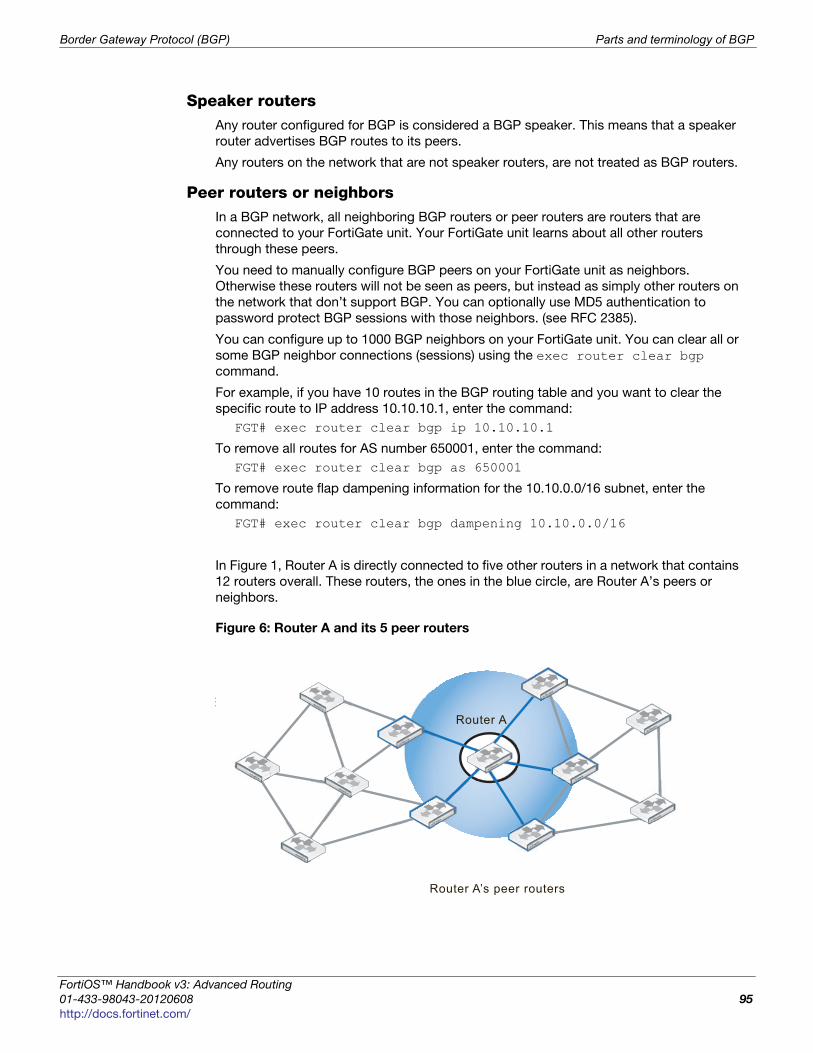
Border Gateway Protocol (BGP) Parts and terminology of BGP
F
0
h
Speaker routersAny router configured for BGP is considered a BGP speaker. This means that a speaker
router advertises BGP routes to its peers.
Any routers on the network that are not speaker routers, are not treated as BGP routers.
Peer routers or neighborsIn a BGP network, all neighboring BGP routers or peer routers are routers that are
connected to your FortiGate unit. Your FortiGate unit learns about all other routers
through these peers.
You need to manually configure BGP peers on your FortiGate unit as neighbors.
Otherwise these routers will not be seen as peers, but instead as simply other routers on
the network that don’t support BGP. You can optionally use MD5 authentication to
password protect BGP sessions with those neighbors. (see RFC 2385).
You can configure up to 1000 BGP neighbors on your FortiGate unit. You can clear all or
some BGP neighbor connections (sessions) using the exec router clear bgp
command.
For example, if you have 10 routes in the BGP routing table and you want to clear the
specific route to IP address 10.10.10.1, enter the command:
FGT# exec router clear bgp ip 10.10.10.1
To remove all routes for AS number 650001, enter the command:
FGT# exec router clear bgp as 650001
To remove route flap dampening information for the 10.10.0.0/16 subnet, enter the
command:
FGT# exec router clear bgp dampening 10.10.0.0/16
In Figure 1, Router A is directly connected to five other routers in a network that contains
12 routers overall. These routers, the ones in the blue circle, are Router A’s peers or
neighbors.
Figure 6: Router A and its 5 peer routers
Border Router
Router A’s peer routers
Router A
ortiOS™ Handbook v3: Advanced Routing
1-433-98043-20120608 95
ttp://docs.fortinet.com/
Parts and terminology of BGP Border Gateway Protocol (BGP)
As a minimum, when configuring BGP neighbors you must enter their IP address, and the
AS number (remote-as). This is all the information the web-based manager interface
allows you to enter for a neighbor.
The BGP commands related to neighbors are quite extensive and include:
config router bgpconfig neighboredit <neighbor_address_ipv4>set activate {enable | disable}set advertisement-interval <seconds_integer>set allowas-in <max_num_AS_integer>set allowas-in-enable {enable | disable}set attribute-unchanged [as-path] [med] [next-hop]set bfd {enable | disable}set capability-default-originate {enable | disable}set capability-dynamic {enable | disable}set capability-graceful-restart {enable | disable}set capability-orf {both | none | receive | send}set capability-route-refresh {enable | disable}set connect-timer <seconds_integer>set description <text_str>set distribute-list-in <access-list-name_str>set distribute-list-out <access-list-name_str>set dont-capability-negotiate {enable | disable}set ebgp-enforce-multihop {enable | disable}set ebgp-multihop {enable | disable}set ebgp-multihop-ttl <seconds_integer>set filter-list-in <aspath-list-name_str>set filter-list-out <aspath-list-name_str>set holdtime-timer <seconds_integer>set interface <interface-name_str>set keep-alive-timer <seconds_integer>set maximum-prefix <prefix_integer>set maximum-prefix-threshold <percentage_integer>set maximum-prefix-warning-only {enable | disable}set next-hop-self {enable | disable}set override-capability {enable | disable}set passive {enable | disable}set password <string>set prefix-list-in <prefix-list-name_str>set prefix-list-out <prefix-list-name_str>set remote-as <id_integer>set remove-private-as {enable | disable}set retain-stale-time <seconds_integer>set route-map-in <routemap-name_str>set route-map-out <routemap-name_str>set route-reflector-client {enable | disable}set route-server-client {enable | disable}set send-community {both | disable | extended | standard}set shutdown {enable | disable}set soft-reconfiguration {enable | disable}set strict-capability-match {enable | disable}set unsuppress-map <route-map-name_str>set update-source <interface-name_str>
Advanced Routing for FortiOS 4.0 MR3
96 01-433-98043-20120608
http://docs.fortinet.com/
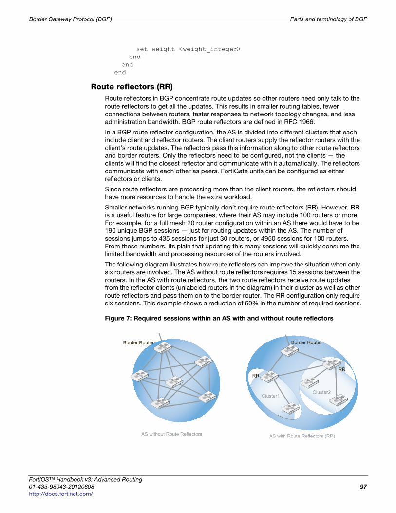
Border Gateway Protocol (BGP) Parts and terminology of BGP
F
0
h
set weight <weight_integer>end
endend
Route reflectors (RR)Route reflectors in BGP concentrate route updates so other routers need only talk to the
route reflectors to get all the updates. This results in smaller routing tables, fewer
connections between routers, faster responses to network topology changes, and less
administration bandwidth. BGP route reflectors are defined in RFC 1966.
In a BGP route reflector configuration, the AS is divided into different clusters that each
include client and reflector routers. The client routers supply the reflector routers with the
client’s route updates. The reflectors pass this information along to other route reflectors
and border routers. Only the reflectors need to be configured, not the clients — the
clients will find the closest reflector and communicate with it automatically. The reflectors
communicate with each other as peers. FortiGate units can be configured as either
reflectors or clients.
Since route reflectors are processing more than the client routers, the reflectors should
have more resources to handle the extra workload.
Smaller networks running BGP typically don’t require route reflectors (RR). However, RR
is a useful feature for large companies, where their AS may include 100 routers or more.
For example, for a full mesh 20 router configuration within an AS there would have to be
190 unique BGP sessions — just for routing updates within the AS. The number of
sessions jumps to 435 sessions for just 30 routers, or 4950 sessions for 100 routers.
From these numbers, its plain that updating this many sessions will quickly consume the
limited bandwidth and processing resources of the routers involved.
The following diagram illustrates how route reflectors can improve the situation when only
six routers are involved. The AS without route reflectors requires 15 sessions between the
routers. In the AS with route reflectors, the two route reflectors receive route updates
from the reflector clients (unlabeled routers in the diagram) in their cluster as well as other
route reflectors and pass them on to the border router. The RR configuration only require
six sessions. This example shows a reduction of 60% in the number of required sessions.
Figure 7: Required sessions within an AS with and without route reflectors
AS with Route Reflectors (RR)
Border Router Border Router
RR
AS without Route Reflectors
RR
Cluster1Cluster2
ortiOS™ Handbook v3: Advanced Routing
1-433-98043-20120608 97
ttp://docs.fortinet.com/
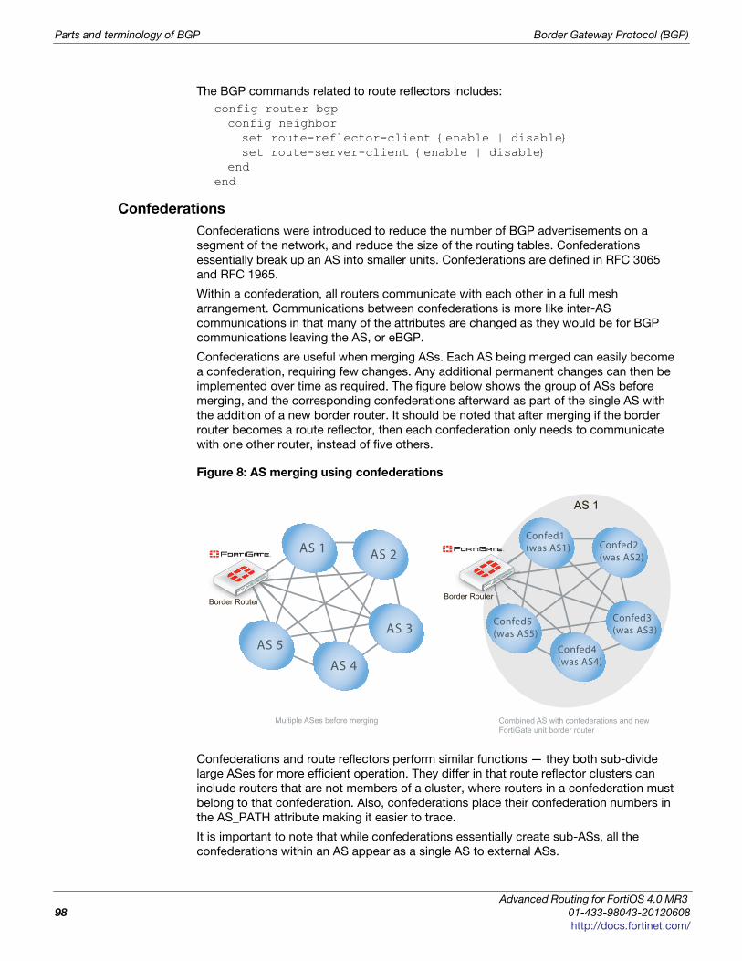
Parts and terminology of BGP Border Gateway Protocol (BGP)
The BGP commands related to route reflectors includes:
config router bgpconfig neighborset route-reflector-client {enable | disable}set route-server-client {enable | disable}
endend
Confederations
Confederations were introduced to reduce the number of BGP advertisements on a
segment of the network, and reduce the size of the routing tables. Confederations
essentially break up an AS into smaller units. Confederations are defined in RFC 3065
and RFC 1965.
Within a confederation, all routers communicate with each other in a full mesh
arrangement. Communications between confederations is more like inter-AS
communications in that many of the attributes are changed as they would be for BGP
communications leaving the AS, or eBGP.
Confederations are useful when merging ASs. Each AS being merged can easily become
a confederation, requiring few changes. Any additional permanent changes can then be
implemented over time as required. The figure below shows the group of ASs before
merging, and the corresponding confederations afterward as part of the single AS with
the addition of a new border router. It should be noted that after merging if the border
router becomes a route reflector, then each confederation only needs to communicate
with one other router, instead of five others.
Figure 8: AS merging using confederations
Confederations and route reflectors perform similar functions — they both sub-divide
large ASes for more efficient operation. They differ in that route reflector clusters can
include routers that are not members of a cluster, where routers in a confederation must
belong to that confederation. Also, confederations place their confederation numbers in
the AS_PATH attribute making it easier to trace.
It is important to note that while confederations essentially create sub-ASs, all the
confederations within an AS appear as a single AS to external ASs.
Combined AS with confederations and new FortiGate unit border router
Border Router
AS 1
Multiple ASes before merging
Confed1(was AS1)
Border Router
AS 1AS 1 AS 2
AS 3
AS 4
AS 5
Confed1(was AS1) Confed2
(was AS2)
Confed3(was AS3)
Confed4(was AS4)
Confed5(was AS5)
B dd RRR trder RRouttttttttter
Advanced Routing for FortiOS 4.0 MR3
98 01-433-98043-20120608
http://docs.fortinet.com/
Border Gateway Protocol (BGP) Parts and terminology of BGP
F
0
h
Confederation related BGP commands include:
config router bgpset confederation-identifier <peerid_integer>
end
Network Layer Reachability Information (NLRI)
Network Layer Reachability Information (NLRI) is unique to BGP-4. It is sent as part of the
update messages sent between BGP routers, and contains information necessary to
supernet, or aggregate route, information. The NLRI includes the length and prefix that
when combined are the address of the aggregated routes referred to.
There is only one NLRI entry per BGP update message.
BGP attributes
Each route in a BGP network has a set of attributes associated with it. These attributes
define the route, and are modified as required along the route.
BGP can work well with mostly default settings, but if you are going to change settings
you need to understand the roles of each attribute and how they affect those settings.
The BGP attributes include:
AS_PATHAS_PATH is the BGP attribute that keeps track of each AS a route advertisement has
passed through. AS_PATH is used by confederations and by exterior BGP (EBGP) to help
prevent routing loops. A router knows there is a loop if it receives an AS_PATH with that
routers AS in it. The figure below shows the route between router A and router B. The
AS_PATH from A to B would read 701,702,703 for each AS the route passes through.
AS_PATHA list of ASes a route has passed through. See “AS_PATH”
on page 99.
MULTI_EXIT_DESC (MED)
Which router to use to exit an AS with more than one
external connection. See “MULTI_EXIT_DESC (MED)” on
page 100.
COMMUNITYUsed to apply attributes to a group of routes. See
“COMMUNITY” on page 100.
NEXT_HOPWhere the IP packets should be forwarded to, like a
gateway in static routing. See “NEXT_HOP” on page 101.
ATOMIC_AGGREGATE
Used when routes have been summarized to tell
downstream routers not to de-aggregate the route. See
“ATOMIC_AGGREGATE” on page 101.
ORIGINUsed to determine if the route is from the local AS or not.
See“ORIGIN” on page 101.
LOCAL_PREFUsed only within an AS to select the best route to a
location (like MED)
Inbound policies on FortiGate units can change the NEXT-HOP,LOCAL-PREF, MED and
AS-PATH attributes of an internal BGP (iBGP) route for its local route selection purposes.
However, outbound policies on the unit cannot affect these attributes.
ortiOS™ Handbook v3: Advanced Routing
1-433-98043-20120608 99
ttp://docs.fortinet.com/
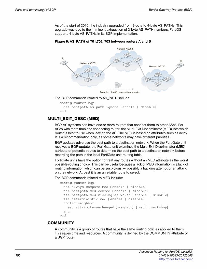
Parts and terminology of BGP Border Gateway Protocol (BGP)
As of the start of 2010, the industry upgraded from 2-byte to 4-byte AS_PATHs. This
upgrade was due to the imminent exhaustion of 2-byte AS_PATH numbers. FortiOS
supports 4-byte AS_PATHs in its BGP implementation.
Figure 9: AS_PATH of 701,702, 703 between routers A and B
The BGP commands related to AS_PATH include:
config router bgpset bestpath-as-path-ignore {enable | disable}
end
MULTI_EXIT_DESC (MED)BGP AS systems can have one or more routers that connect them to other ASes. For
ASes with more than one connecting router, the Multi-Exit Discriminator (MED) lists which
router is best to use when leaving the AS. The MED is based on attributes such as delay.
It is a recommendation only, as some networks may have different priorities.
BGP updates advertise the best path to a destination network. When the FortiGate unit
receives a BGP update, the FortiGate unit examines the Multi-Exit Discriminator (MED)
attribute of potential routes to determine the best path to a destination network before
recording the path in the local FortiGate unit routing table.
FortiGate units have the option to treat any routes without an MED attribute as the worst
possible routing choice. This can be useful because a lack of MED information is a lack of
routing information which can be suspicious — possibly a hacking attempt or an attack
on the network. At best it is an unreliable route to select.
The BGP commands related to MED include:
config router bgpset always-compare-med {enable | disable}set bestpath-med-confed {enable | disable}set bestpath-med-missing-as-worst {enable | disable}set deterministic-med {enable | disable}config neighborset attribute-unchanged [as-path] [med] [next-hop]
endend
COMMUNITYA community is a group of routes that have the same routing policies applied to them.
This saves time and resources. A community is defined by the COMMUNITY attribute of
a BGP route.
A
Network AS701Network AS703
Network AS702
B
3 12
Direction of traffic across the networks
Advanced Routing for FortiOS 4.0 MR3
100 01-433-98043-20120608
http://docs.fortinet.com/
Border Gateway Protocol (BGP) Parts and terminology of BGP
F
0
h
The FortiGate unit can set the COMMUNITY attribute of a route to assign the route to
predefined paths (see RFC 1997). The FortiGate unit can examine the COMMUNITY
attribute of learned routes to perform local filtering and/or redistribution.
The BGP commands related to COMMUNITY include:
config router bgpset send-community {both | disable | extended | standard}
end
NEXT_HOPThe NEXT_HOP attribute says what IP address the packets should be forwarded to next.
Each time the route is advertised, this value is updated. The NEXT_HOP attribute is much
like a gateway in static routing.
FortiGate units allow you to to change the advertising of the FortiGate unit’s IP address
(instead of the neighbor’s IP address) in the NEXT_HOP information that is sent to IBGP
peers. This is changed with the config neighbor, set next-hop-self command.
The BGP commands related to NEXT_HOP include:
config router bgpconfig neighborset attribute-unchanged [as-path] [med] [next-hop]set next-hop-self {enable | disable}
endend
ATOMIC_AGGREGATEThe ATOMIC_AGGREGATE attribute is used when routes have been summarized. It
indicates which AS and which router summarize the routes. It also tells downstream
routers not to de-aggregate the route. Summarized routes are routes with similar
information that have been combined, or aggregated, into one route that is easier to send
in updates. When it reaches its destination, the summarized routes are split back up into
the individual routes.
Your FortiGate unit doesn’t specifically set this attribute in the BGP router command, but
it is used in the route map command.
The commands related to ATOMIC_AGGREGATE include:
config router route-mapedit <route_map_name>config ruleedit <route_map_rule_id>set set-aggregator-as <id_integer>set set-aggregator-ip <address_ipv4>set set-atomic-aggregate {enable | disable}
endend
end
ORIGINThe ORIGIN attribute records where the route came from. The options can be IBGP,
EBGP, or incomplete. This information is important because internal routes (IBGP) are
higher priority than external routes (EBGP). However incomplete ORIGINs are the lowest
priority of the three.
ortiOS™ Handbook v3: Advanced Routing
1-433-98043-20120608 101
ttp://docs.fortinet.com/
How BGP works Border Gateway Protocol (BGP)
The commands related to ORIGIN include:
config router route-mapedit <route_map_name>set comments <string>config ruleedit <route_map_rule_id>set match-origin {egp | igp | incomplete | none}
endend
end
How BGP works
BGP is a link-state routing protocol and keeps link-state information about the status of
each network link it has connected. A BGP router receives information from its peer
routers that have been defined as neighbors. BGP routers listen for updates from these
configured neighboring routers on TCP port 179.
A BGP router is a finite state machine with six various states for each connection. As two
BGP routers discover each other, and establish a connection they go from the idle state,
through the various states until they reach the established state. An error cancan cause
the connection to be dropped and the state of the router to be reset to either active or
idle. These errors can be caused by: TCP port 179 not being open, a random TCP port
above port 1023 not being open, the peer address being incorrect, or the AS number
being incorrect.
When BGP routers start a connection, they negotiate which (if any) optional features will
be used such as multiprotocol extensions that can include IPv6 and VPNs.
IBGP versus EBGP
When you read about BGP, often you see EBGP or IBGP mentioned. These are both BGP
routing, but BGP used in different roles. Exterior BGP (EBGP) involves packets crossing
multiple autonomous systems (ASes) where interior BGP (IBGP) involves packets that
stay within a single AS. For example the AS_PATH attribute is only useful for EBGP where
routes pass through multiple ASes.
These two modes are important because some features of BGP are only used for one of
EBGP or IBGP. For example confederations are used in EBGP, and route reflectors are
only used in IBGP. Also routes learned from IBGP have priority over EBGP learned routes.
FortiGate units have some commands specific to EBGP. These include:
• automatically resetting the session information to external peers if the connection
goes down — set fast-external-failover {enable | disable}
• setting an administrative distance for all routes learned from external peers (must also
configure local and internal distances if this is set) — set distance-external <distance_integer>
• enforcing EBGP multihops and their TTL (number of hops) — set ebgp-enforce-multihop {enable | disable} and set ebgp-multihop-ttl <seconds_integer>
BGP path determination — which route to use
All learned routes and their attributes come into the BGP router in raw form. Before
routes are installed in the routing table or are advertised to other routers, three levels of
decisions must be made.
Advanced Routing for FortiOS 4.0 MR3
102 01-433-98043-20120608
http://docs.fortinet.com/
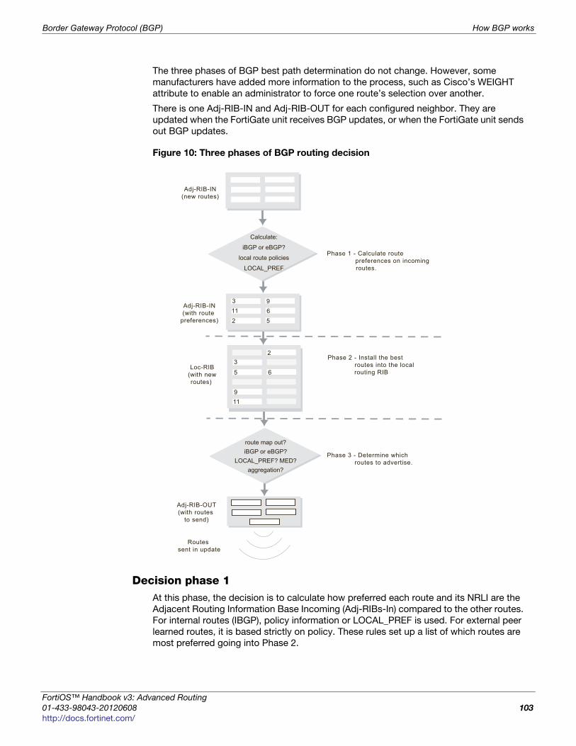
Border Gateway Protocol (BGP) How BGP works
F
0
h
The three phases of BGP best path determination do not change. However, some
manufacturers have added more information to the process, such as Cisco’s WEIGHT
attribute to enable an administrator to force one route’s selection over another.
There is one Adj-RIB-IN and Adj-RIB-OUT for each configured neighbor. They are
updated when the FortiGate unit receives BGP updates, or when the FortiGate unit sends
out BGP updates.
Figure 10: Three phases of BGP routing decision
Decision phase 1At this phase, the decision is to calculate how preferred each route and its NRLI are the
Adjacent Routing Information Base Incoming (Adj-RIBs-In) compared to the other routes.
For internal routes (IBGP), policy information or LOCAL_PREF is used. For external peer
learned routes, it is based strictly on policy. These rules set up a list of which routes are
most preferred going into Phase 2.
Calculate:
iBGP or eBGP?
local route policies
LOCAL_PREF
Phase 1 - Calculate route preferences on incoming
routes.
Adj-RIB-IN(new routes)
3
2
9
5611
Adj-RIB-IN(with route
preferences)
Phase 2 - Install the best routes into the local
routing RIB Loc-RIB
(with newroutes)
2
35 6
911
Phase 3 - Determine which routes to advertise.
Adj-RIB-OUT(with routes
to send)
Routes sent in update
route map out?iBGP or eBGP?
LOCAL_PREF? MED?aggregation?
23
5 6
ortiOS™ Handbook v3: Advanced Routing
1-433-98043-20120608 103
ttp://docs.fortinet.com/
How BGP works Border Gateway Protocol (BGP)
Decision phase 2Phase 2 involves installing the best route to each destination into the local Routing
Information Base (Loc-RIB). Effectively, the Loc-RIB is the master routing table. Each
route from Phase 1 has their NEXT_HOP checked to ensure the destination is reachable.
If it is reachable, the AS_PATH is checked for loops. After that, routes are installed based
on the following decision process:
• If there is only one route to a location, it is installed.
• If multiple routes to the same location, use the most preferred route from Level 1.
• If there is a tie, break the tie based on the following in descending order of
importance: shortest AS_PATH, smallest ORIGIN number, smallest MED, EBGP over
IBGP, smallest metric or cost for reaching the NEXT_HOP, BGP identifier, and lowest
IP address.
Note that the new routes that are installed into the Loc-RIB are in addition to any existing
routes in the table. Once Phase 2 is completed the Loc-RIB will consist of the best of
both the new and older routes.
Decision phase 3Phase 3 is route distribution or dissemination. This is the process of deciding which
routes the router will advertise. If there is any route aggregation or summarizing, it
happens here. Also any route filtering from route maps happens here.
Once Phase 3 is complete, an update can be sent out to update the neighbor of new
routes.
Aggregate routes and addressesBGP4 allows classless routing, which uses netmasks as well as IP addresses. This
classless routing enables the configuration of aggregate routes by stating the address
bits the aggregated addresses have in common. For more information, see “Aggregated
routes and addresses” on page 50.
In BGP there is an ATOMIC_AGGREGATE attribute that when set informs routers that the
route has been aggregated, and should not be de-aggregated. An associated
AGGREGATOR attribute include the information about the router that did the aggregating
including its AS.
The BGP commands associated with aggregate routes and addresses are:
config router bgpconfig aggregate-addressedit <aggr_addr_id>set as-set {enable | disable}set prefix <address_ipv4mask>set summary-only {enable | disable}
endconfig aggregate-address6edit <aggr_addr_id>set as-set {enable | disable}set prefix6 <address_ipv6mask>set summary-only {enable | disable}
endend
Advanced Routing for FortiOS 4.0 MR3
104 01-433-98043-20120608
http://docs.fortinet.com/
Border Gateway Protocol (BGP) Troubleshooting BGP
F
0
h
Troubleshooting BGP
There are some features in BGP that are used to deal with problems that may arise.
Typically the problems with a BGP network that has been configured, involve routes
going offline frequently. This is called route flap and causes problems for the routers
using that route.
This section includes:
• Clearing routing table entries
• Route flap
Clearing routing table entries
To see if a new route is being properly added to the routing table, you can clear all or
some BGP neighbor connections (sessions) using the exec router clear bgp
command.
For example, if you have 10 routes in the BGP routing table and you want to clear the
specific route to IP address 10.10.10.1, enter the command:
FGT# exec router clear bgp ip 10.10.10.1
To remove all routes for AS number 650001, enter the command:
FGT# exec router clear bgp as 650001
Route flap
When routers or hardware along a route go offline and back online that is called a route
flap. Flapping is the term if these outages continue, especially if they occur frequently.
Route flap is a problem in BGP because each time a peer or a route goes down, all the
peer routers that are connected to that out-of-service router advertise the change in their
routing tables which creates a lot of administration traffic on the network. And the same
traffic happens again when that router comes back online. If the problem is something
like a faulty network cable that wobbles on and offline every 10 seconds, there could
easily be overwhelming amounts of routing updates sent out unnecessarily.
Another possible reason for route flap occurs with multiple FortiGate units in HA mode.
When an HA cluster fails over to the secondary unit, other routers on the network may
see the HA cluster as being offline resulting in route flap. While this doesn’t occur often,
or more than once at a time, it can still result in an interruption in traffic which is
unpleasant for network users. The easy solution for this problem is to increase the timers
on the HA cluster, such as TTL timers, so they do not expire during the failover process.
Also configuring graceful restart on the HA cluster will help with a smooth failover.
The first method of dealing with router flap should be to check your hardware. If a cable is
loose or bad, it can easily be replaced and eliminate the problem. If an interface on the
router is bad, either don’t use that interface or swap in a good router. If the power source
is bad on a router either replace the power supply or use a power conditioning backup
power supply. These quick and easy fixes can save you from configuring more complex
BGP options. However if the route flap is from another source, configuring BGP to deal
with the outages will ensure your network users uninterrupted service.
Some methods of dealing with route flap in BGP include:
• Holddown timer
• Dampening
• Graceful restart
• Bi-directional forwarding detection (BFD)
ortiOS™ Handbook v3: Advanced Routing
1-433-98043-20120608 105
ttp://docs.fortinet.com/
Troubleshooting BGP Border Gateway Protocol (BGP)
Holddown timerThe first line of defence to a flapping route is the hold down timer. This timer reduces how
frequently a route going down will cause a routing update to be broadcast.
Once activated, the holddown timer won’t allow the FortiGate unit to accept any changes
to that route for the duration of the timer. If the route flaps five times during the timer
period, only the first outage will be recognized by the FortiGate unit — for the duration of
the other outages there will be no changes because the Fortigate unit is essentially
treating this router as down. After the timer expires, if the route is still flapping it will
happen all over again.
Even if the route isn’t flapping — if it goes down, comes up, and stays back up — the
timer still counts down and the route is ignored for the duration of the timer. In this
situation the route will be seen as down longer than it really is, but there will be only the
one set of route updates. This is not a problem in normal operation because updates are
not frequent.
Also the potential for a route to be treated as down when it is really up can be viewed as
a robustness feature. Typically you do not want most of your traffic being routed over an
unreliable route. So if there is route flap going on, it is best to avoid that route if you can.
This is enforced by the holddown timer.
How to configure the holddown timer
There are three different route flapping situations that can occur: the route goes up and
down frequently, the route goes down and back up once over a long period of time, or the
route goes down and stays down for a long period of time. These can all be handled
using the holddown timer.
For example, your network has two routes that you want to set the holddown timer for.
One is your main route ( to 10.12.101.4) that all your Internet traffic goes through, and it
can’t be down for long if its down. The second is a low speed connection to a custom
network that is used infrequently ( to 10.13.101.4). The holddown timer for the main route
should be fairly short, lets say 60 seconds instead of the default 180 seconds. The
second route timer can be left at the default or even longer since it is rarely used. In your
BGP configuration this looks like:
config router bgpconfig neighboredit 10.12.101.4set holddown-timer 60
nextedit 10.13.101.4set holddown-timer 180
nextend
end
Advanced Routing for FortiOS 4.0 MR3
106 01-433-98043-20120608
http://docs.fortinet.com/
Border Gateway Protocol (BGP) Troubleshooting BGP
F
0
h
DampeningDampening is a method used to limit the amount of network problems due to flapping
routes. With dampening the flapping still occurs, but the peer routers pay less and less
attention to that route as it flaps more often. One flap doesn’t start dampening, but the
second starts a timer where the router will not use that route — it is considered unstable.
If the route flaps again before the timer expires, the timer continues to increase. There is a
period of time called the reachability half-life after which a route flap will only be
suppressed for half the time. This half-life comes into effect when a route has been stable
for a while but not long enough to clear all the dampening completely. For the flapping
route to be included in the routing table again, the suppression time must expire.
If the route flapping was temporary, you can clear the flapping or dampening from the
FortiGate units cache by using one of the execute router clear bgp commands:
execute router clear bgp dampening {<ip_address> | <ip/netmask>}
or
execute router clear bgp flap-statistics {<ip_address> | <ip/netmask>}
For example, to remove route flap dampening information for the 10.10.0.0/16 subnet,
enter the command:
FGT# exec router clear bgp dampening 10.10.0.0/16
The BGP commands related to route dampening are:
config router bgpset dampening {enable | disable}set dampening-max-suppress-time <minutes_integer>set dampening-reachability-half-life <minutes_integer>set dampening-reuse <reuse_integer>set dampening-route-map <routemap-name_str>set dampening-suppress <limit_integer>set dampening-unreachability-half-life <minutes_integer>end
end
Graceful restartBGP4 has the capability to gracefully restart.
In some situations, route flap is caused by routers that appear to be offline but the
hardware portion of the router (control plane) can continue to function normally. One
example of this is when some software is restarting or being upgraded, but the hardware
can still function normally.
Graceful restart is best used for these situations where routing will not be interrupted, but
the router is unresponsive to routing update advertisements. Graceful restart does not
have to be supported by all routers in a network, but the network will benefit when more
routers support it.
FortiGate HA clusters can benefit from graceful restart. When a failover takes place, the
HA cluster will advertise it is going offline, and will not appear as a route flap. It will also
enable the new HA main unit to come online with an updated and usable routing table —
if there is a flap the HA cluster routing table will be out of date.
ortiOS™ Handbook v3: Advanced Routing
1-433-98043-20120608 107
ttp://docs.fortinet.com/
Troubleshooting BGP Border Gateway Protocol (BGP)
Scheduled time offlineGraceful restart is a means for a router to advertise it is going to have a scheduled
shutdown for a very short period of time. When neighboring routers receive this notice,
they will not remove that router from their routing table until after a set time elapses.
During that time if the router comes back online, everything continues to function as
normal. If that router remains offline longer than expected, then the neighboring routers
will update their routing tables as they assume that router will be offline for a long time.
FortiGate units support both graceful restart of their own BGP routing software, and also
neighboring BGP routers.
For example, if a neighbor of your FortiGate unit, with an IP address of 172.20.120.120,
supports graceful restart, enter the command:
config router bgpconfig neighbor edit 172.20.120.120set capapbility-graceful-restart enable
end end
If you want to configure graceful restart on your FortiGate unit where you expect the
Fortigate unit to be offline for no more than 2 minutes, and after 3 minutes the BGP
network should consider the FortiGate unit offline, enter the command:
config router bgpset graceful-restart enableset graceful-restart-time 120set graceful-stalepath-time 180
end
The BGP commands related to BGP graceful restart are:
config router bgpset graceful-restart { disable| enable}set graceful-restart-time <seconds_integer>set graceful-stalepath-time <seconds_integer>config neighborset capability-graceful-restart {enable | disable}
endend
execute router restart
Bi-directional forwarding detection (BFD)Bi-directional Forwarding Detection (BFD) is a protocol used to quickly locate hardware
failures in the network. Routers running BFD communicate with each other, and if a timer
runs out on a connection then that router is declared down. BFD then communicates this
information to the routing protocol and the routing information is updated.
You can configure graceful restarting and other advanced settings only through CLI
commands. For more information on advanced BGP settings, see the “router” chapter
of the FortiGate CLI Reference.
Advanced Routing for FortiOS 4.0 MR3
108 01-433-98043-20120608
http://docs.fortinet.com/
Border Gateway Protocol (BGP) BGP routing examples
F
0
h
While BGP can detect route failures, BFD can be configured to detect these failures more
quickly allowing faster responses and improved convergence. This can be balanced with
the bandwidth BFD uses in its frequent route checking.
Configurable granularityBFD can run on the entire FortiGate unit, selected interfaces, or on BGP for all configured
interfaces. The hierarchy allows each lower level to override the upper level’s BFD setting.
For example, if BFD was enabled for the FortiGate unit, it could be disabled only for a
single interface or for BGP. For information about FortiGate-wide BFD options, see config
system settings in the FortiGate CLI Reference.
BFD support was added in FortiOS v3.0 MR4, and can only be configured through the
CLI.
The BGP commands related to BFD are:
config router bgpconfig neighboredit <neighbor_address_ipv4>set bfd {enable | disable}
endend
execute router clear bfd session <src_ipv4> <dst_ipv4> <interface>
BGP routing examples
BGP is a complex dynamic routing protocol. There are many BGP configurations and
features that can benefit from in-depth examples.
This section includes:
• Dual-homed BGP example
• Redistributing and blocking routes in BGP
Dual-homed BGP example
This is an example of a small network that uses BGP routing connections to two ISPs.
This is a common configuration for companies that need redundant connections to the
Internet for their business.
This configuration is for a small company connected to two ISPs. The company has one
main office, the Head Office, and uses static routing for internal routing on that network.
Both ISPs use BGP routing, and connect to the Internet directly. They want the company
to connect to the ISP networks using BGP. They also use graceful restart to prevent
unneeded updates, and use smaller timer values to detect network failures faster.
As can be expected, the company wants to keep their BGP configuration relatively
simple and easy to manage. The current configuration has only 3 routers to worry about
— the 2 ISP border routers, and the FortiGate unit. This means the FortiGate unit will
only have two neighbour routers to configure.
This configuration has the added benefit of being easy to expand if the Company wants
to add a remote office in the future.
ortiOS™ Handbook v3: Advanced Routing
1-433-98043-20120608 109
ttp://docs.fortinet.com/
Dual-homed BGP example Border Gateway Protocol (BGP)
To keep the configuration simple, the Company is allowing only HTTP, HTTPS, FTP, and
DNS traffic out of the local network. This will allow employees access to the Internet and
their web-mail.
This section includes the following topics:
• Network layout and assumptions
• General configuration steps
• Configuring the FortiGate unit
• Configuring other networking devices
• Testing this configuration
Why dual home?Dual homing means having two separate independent connections to the Internet.
Servers in this configuration have also been called bastion hosts and can include DNS
servers which require multiple connections.
Benefits of dual homing can include:
• redundant Internet connection that essentially never fails
• faster connections through one ISP or the other for some destinations, such as other
clients of those ISPs
• load balancing traffic to your Company network
• easier to enable more traffic through two connections than upgrading one connection
to bigger bandwidth
• easier to create protection policies for different traffic through a specific ISP
Some companies require reliable internet access at all times as part of their business.
Consider a doctor operating remotely who has their Internet connection fail — the
consequences could easily be life or death.
Dual homing is extra expense for the second ISP connection, and more work to configure
and maintain the more complex network topology.
Potential dual homing issuesBGP comes with load balancing issues, and dual homing is the same category. BGP
does not inherently deal well with load balancing, or getting default routes through BGP.
Ideally one connect may be best for certain destinations, but it may not have that traffic
routed to it making the load balancing less than perfect. This kind of fine tuning can be
very time consuming, and usually results in a best effort situation.
When dual coming is not configured properly, your network may become a link between
your ISPs and result in very high traffic between the ISPs that does not originate from
your network. The problems with this situation are that your traffic may not have the
bandwidth it needs, and you will be paying for a large volume of traffic that is not yours.
This problem can be solved by not broadcasting or redistributing BGP routes between
the ISPs.
Advanced Routing for FortiOS 4.0 MR3
110 01-433-98043-20120608
http://docs.fortinet.com/
Border Gateway Protocol (BGP) Dual-homed BGP example
F
0
h
If you learn your default routes from the ISPs in this example, you may run into an
asymmetric routing problem where your traffic loops out one ISP and back to you
through the other ISP. If you think this may be happening you can turn on asymmetric
routing on the FortiGate unit (config system settings, set asymmetric enable) to verify that
really is the problem. Turn this feature off once this is established since it disables many
features on the FortiGate by disabling stateful inspection. Solutions for this problem can
include using static routes for default routes instead of learning them through BGP, or
configuring VDOMs on your FortiGate unit to provide a slightly different path back that is
not a true loop.
Network layout and assumptions
This section includes:
• Network layout
• Assumptions
Network layoutThe network layout for the basic BGP example involves the company network being
connected to both ISPs as shown below. In this configuration the FortiGate unit is the
BGP border router between the Company AS, ISP1’s AS, and ISP2’s AS.
The components of the layout include:
• The Company AS (AS number 1) is connected to ISP1 and ISP2 through the FortiGate
unit.
• The Company has one internal network — the Head Office network at 10.11.101.0/24.
• The FortiGate unit internal interface is on the the Company internal network with an IP
address of 10.11.101.110.
• The FortiGate unit external1 interface is connected to ISP1’s network with an IP
address of 172.21.111.5, an address supplied by the ISP.
• ISP1 AS has an AS number of 6501, and ISP2 has an AS number of 6502
• Both ISPs are connected to the Internet.
• The ISP1 border router is a neighbor (peer) of the FortiGate unit. It has an address of
172.21.111.4.
• The ISP2 border router is a neighbor (peer) of the FortiGate unit. It has an address of
172.22.222.4.
• Apart from graceful restart, and shorter timers (holdtimer, and keepalive) default
settings are to be used whenever possible.
ortiOS™ Handbook v3: Advanced Routing
1-433-98043-20120608 111
ttp://docs.fortinet.com/
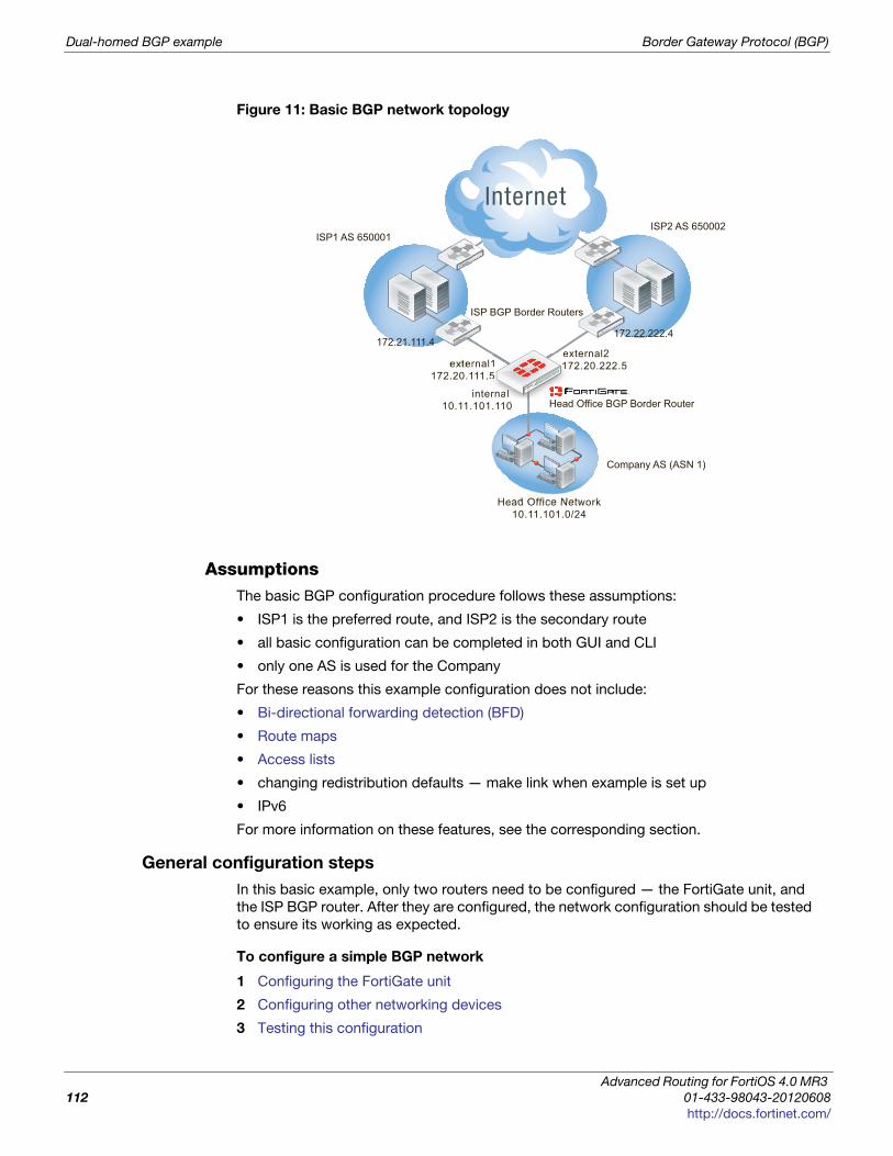
Dual-homed BGP example Border Gateway Protocol (BGP)
Figure 11: Basic BGP network topology
AssumptionsThe basic BGP configuration procedure follows these assumptions:
• ISP1 is the preferred route, and ISP2 is the secondary route
• all basic configuration can be completed in both GUI and CLI
• only one AS is used for the Company
For these reasons this example configuration does not include:
• Bi-directional forwarding detection (BFD)
• Route maps
• Access lists
• changing redistribution defaults — make link when example is set up
• IPv6
For more information on these features, see the corresponding section.
General configuration steps
In this basic example, only two routers need to be configured — the FortiGate unit, and
the ISP BGP router. After they are configured, the network configuration should be tested
to ensure its working as expected.
To configure a simple BGP network
1 Configuring the FortiGate unit
2 Configuring other networking devices
3 Testing this configuration
Company AS (ASN 1)
external1172.20.111.5
Head Office BGP Border Router internal
10.11.101.110
Head Office Network10.11.101.0/24
ISP BGP Border Routers
172.22.222.4
ISP2 AS 650002
172.21.111.4 external2 172.20.222.5 1
555
rnanalllllll
e11
ISP1 AS 650001
Advanced Routing for FortiOS 4.0 MR3
112 01-433-98043-20120608
http://docs.fortinet.com/
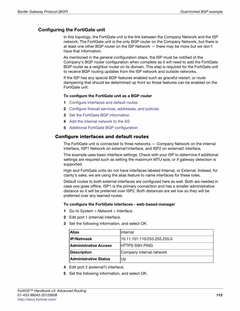
Border Gateway Protocol (BGP) Dual-homed BGP example
F
0
h
Configuring the FortiGate unit
In this topology, the FortiGate unit is the link between the Company Network and the ISP
network. The FortiGate unit is the only BGP router on the Company Network, but there is
at least one other BGP router on the ISP Network — there may be more but we don’t
have that information.
As mentioned in the general configuration steps, the ISP must be notified of the
Company’s BGP router configuration when complete as it will need to add the FortiGate
BGP router as a neighbor router on its domain. This step is required for the FortiGate unit
to receive BGP routing updates from the ISP network and outside networks.
If the ISP has any special BGP features enabled such as graceful restart, or route
dampening that should be determined up front so those features can be enabled on the
FortiGate unit.
To configure the FortiGate unit as a BGP router
1 Configure interfaces and default routes
2 Configure firewall services, addresses, and policies
3 Set the FortiGate BGP information
4 Add the internal network to the AS
5 Additional FortiGate BGP configuration
Configure interfaces and default routesThe FortiGate unit is connected to three networks — Company Network on the internal
interface, ISP1 Network on external1interface, and ISP2 on external2 interface.
This example uses basic interface settings. Check with your ISP to determine if additional
settings are required such as setting the maximum MTU size, or if gateway detection is
supported.
High end FortiGate units do not have interfaces labeled Internal, or External. Instead, for
clarity’s sake, we are using the alias feature to name interfaces for these roles.
Default routes to both external interfaces are configured here as well. Both are needed in
case one goes offline. ISP1 is the primary connection and has a smaller administrative
distance so it will be preferred over ISP2. Both distances are set low so they will be
preferred over any learned routes.
To configure the FortiGate interfaces - web-based manager
1 Go to System > Network > Interface.
2 Edit port 1 (internal) interface.
3 Set the following information, and select OK.
4 Edit port 2 (external1) interface.
5 Set the following information, and select OK.
Alias internal
IP/Netmask 10.11.101.110/255.255.255.0
Administrative Access HTTPS SSH PING
Description Company internal network
Administrative Status Up
ortiOS™ Handbook v3: Advanced Routing
1-433-98043-20120608 113
ttp://docs.fortinet.com/
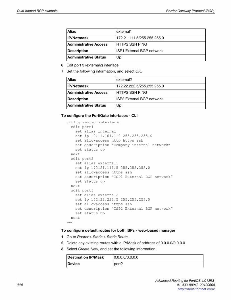
Dual-homed BGP example Border Gateway Protocol (BGP)
6 Edit port 3 (external2) interface.
7 Set the following information, and select OK.
To configure the FortiGate interfaces - CLI
config system interfaceedit port1set alias internalset ip 10.11.101.110 255.255.255.0set allowaccess http https sshset description “Company internal network”set status up
nextedit port2set alias external1set ip 172.21.111.5 255.255.255.0set allowaccess https sshset description “ISP1 External BGP network”set status up
nextedit port3set alias external2set ip 172.22.222.5 255.255.255.0set allowaccess https sshset description “ISP2 External BGP network”set status up
nextend
To configure default routes for both ISPs - web-based manager
1 Go to Router > Static > Static Route.
2 Delete any existing routes with a IP/Mask of address of 0.0.0.0/0.0.0.0
3 Select Create New, and set the following information.
Alias external1
IP/Netmask 172.21.111.5/255.255.255.0
Administrative Access HTTPS SSH PING
Description ISP1 External BGP network
Administrative Status Up
Alias external2
IP/Netmask 172.22.222.5/255.255.255.0
Administrative Access HTTPS SSH PING
Description ISP2 External BGP network
Administrative Status Up
Destination IP/Mask 0.0.0.0/0.0.0.0
Device port2
Advanced Routing for FortiOS 4.0 MR3
114 01-433-98043-20120608
http://docs.fortinet.com/
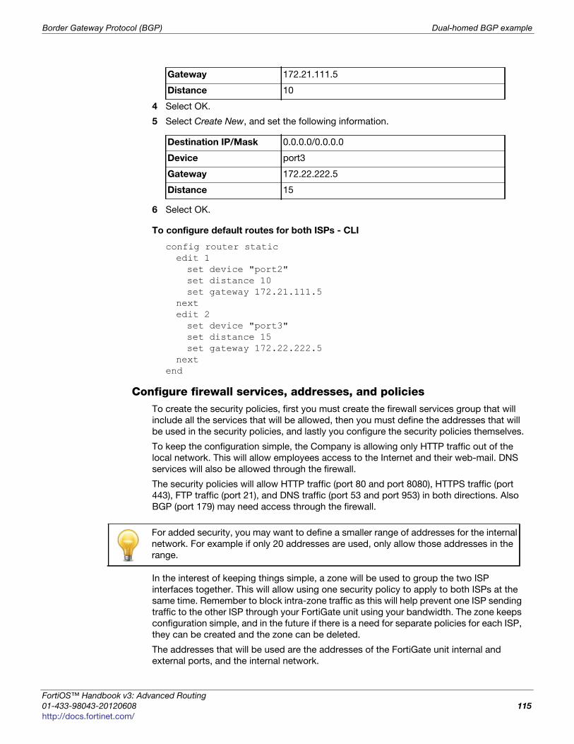
Border Gateway Protocol (BGP) Dual-homed BGP example
F
0
h
4 Select OK.
5 Select Create New, and set the following information.
6 Select OK.
To configure default routes for both ISPs - CLI
config router staticedit 1set device "port2"set distance 10set gateway 172.21.111.5
nextedit 2set device "port3"set distance 15set gateway 172.22.222.5
nextend
Configure firewall services, addresses, and policiesTo create the security policies, first you must create the firewall services group that will
include all the services that will be allowed, then you must define the addresses that will
be used in the security policies, and lastly you configure the security policies themselves.
To keep the configuration simple, the Company is allowing only HTTP traffic out of the
local network. This will allow employees access to the Internet and their web-mail. DNS
services will also be allowed through the firewall.
The security policies will allow HTTP traffic (port 80 and port 8080), HTTPS traffic (port
443), FTP traffic (port 21), and DNS traffic (port 53 and port 953) in both directions. Also
BGP (port 179) may need access through the firewall.
In the interest of keeping things simple, a zone will be used to group the two ISP
interfaces together. This will allow using one security policy to apply to both ISPs at the
same time. Remember to block intra-zone traffic as this will help prevent one ISP sending
traffic to the other ISP through your FortiGate unit using your bandwidth. The zone keeps
configuration simple, and in the future if there is a need for separate policies for each ISP,
they can be created and the zone can be deleted.
The addresses that will be used are the addresses of the FortiGate unit internal and
external ports, and the internal network.
Gateway 172.21.111.5
Distance 10
Destination IP/Mask 0.0.0.0/0.0.0.0
Device port3
Gateway 172.22.222.5
Distance 15
For added security, you may want to define a smaller range of addresses for the internal
network. For example if only 20 addresses are used, only allow those addresses in the
range.
ortiOS™ Handbook v3: Advanced Routing
1-433-98043-20120608 115
ttp://docs.fortinet.com/
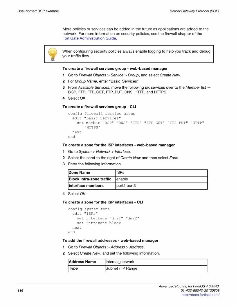
Dual-homed BGP example Border Gateway Protocol (BGP)
More policies or services can be added in the future as applications are added to the
network. For more information on security policies, see the firewall chapter of the
FortiGate Administration Guide.
To create a firewall services group - web-based manager
1 Go to Firewall Objects > Service > Group, and select Create New.
2 For Group Name, enter “Basic_Services”.
3 From Available Services, move the following six services over to the Member list —
BGP, FTP, FTP_GET, FTP_PUT, DNS, HTTP, and HTTPS.
4 Select OK.
To create a firewall services group - CLI
config firewall service groupedit "Basic_Services"set member "BGP" "DNS" "FTP" "FTP_GET" "FTP_PUT" "HTTP"
"HTTPS" next
end
To create a zone for the ISP interfaces - web-based manager
1 Go to System > Network > Interface.
2 Select the caret to the right of Create New and then select Zone.
3 Enter the following information.
4 Select OK.
To create a zone for the ISP interfaces - CLI
config system zoneedit "ISPs"set interface "dmz1" "dmz2" set intrazone block
nextend
To add the firewall addresses - web-based manager
1 Go to Firewall Objects > Address > Address.
2 Select Create New, and set the following information.
When configuring security policies always enable logging to help you track and debug
your traffic flow.
Zone Name ISPs
Block Intra-zone traffic enable
interface members port2 port3
Address Name Internal_network
Type Subnet / IP Range
Advanced Routing for FortiOS 4.0 MR3
116 01-433-98043-20120608
http://docs.fortinet.com/
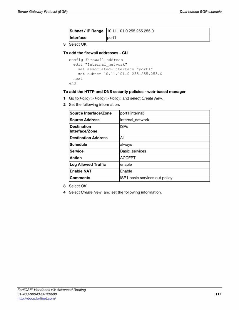
Border Gateway Protocol (BGP) Dual-homed BGP example
F
0
h
3 Select OK.
To add the firewall addresses - CLI
config firewall addressedit "Internal_network"set associated-interface "port1"set subnet 10.11.101.0 255.255.255.0
nextend
To add the HTTP and DNS security policies - web-based manager
1 Go to Policy > Policy > Policy, and select Create New.
2 Set the following information.
3 Select OK.
4 Select Create New, and set the following information.
Subnet / IP Range 10.11.101.0 255.255.255.0
Interface port1
Source Interface/Zone port1(internal)
Source Address Internal_network
Destination
Interface/Zone
ISPs
Destination Address All
Schedule always
Service Basic_services
Action ACCEPT
Log Allowed Traffic enable
Enable NAT Enable
Comments ISP1 basic services out policy
ortiOS™ Handbook v3: Advanced Routing
1-433-98043-20120608 117
ttp://docs.fortinet.com/
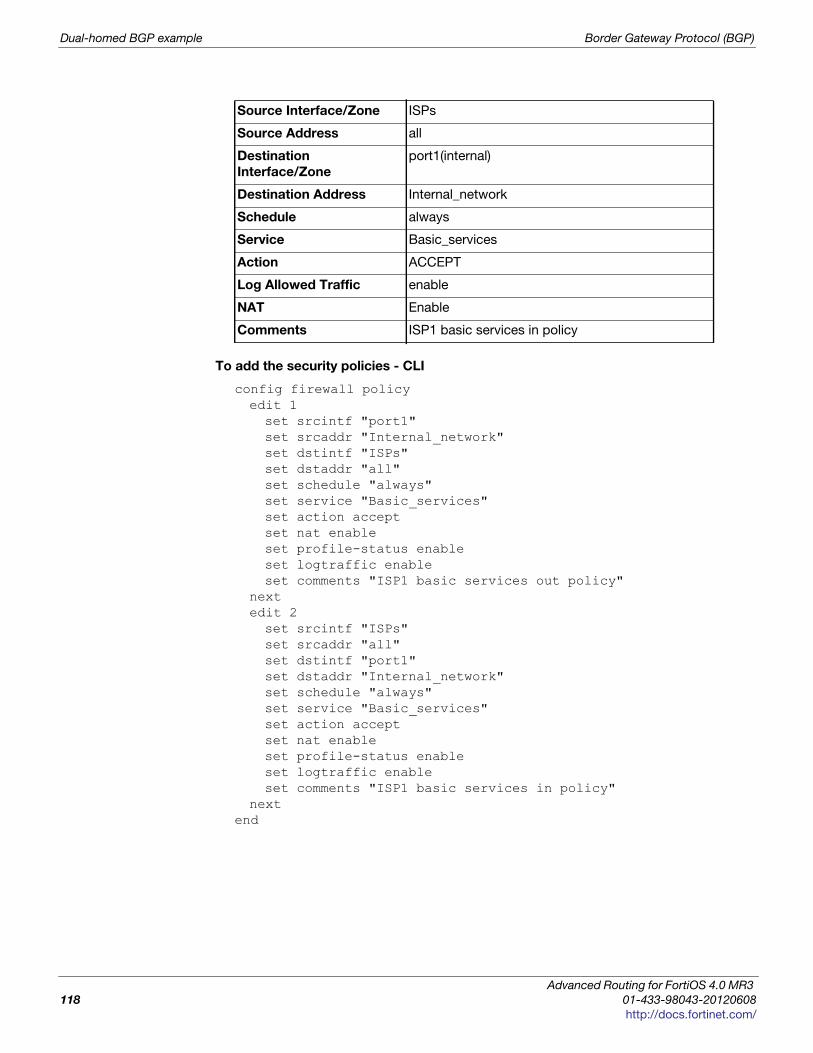
Dual-homed BGP example Border Gateway Protocol (BGP)
To add the security policies - CLI
config firewall policyedit 1set srcintf "port1"set srcaddr "Internal_network" set dstintf "ISPs"set dstaddr "all" set schedule "always"set service "Basic_services" set action acceptset nat enableset profile-status enableset logtraffic enableset comments "ISP1 basic services out policy"
nextedit 2set srcintf "ISPs"set srcaddr "all" set dstintf "port1"set dstaddr "Internal_network" set schedule "always"set service "Basic_services" set action acceptset nat enableset profile-status enableset logtraffic enableset comments "ISP1 basic services in policy"
nextend
Source Interface/Zone ISPs
Source Address all
Destination
Interface/Zone
port1(internal)
Destination Address Internal_network
Schedule always
Service Basic_services
Action ACCEPT
Log Allowed Traffic enable
NAT Enable
Comments ISP1 basic services in policy
Advanced Routing for FortiOS 4.0 MR3
118 01-433-98043-20120608
http://docs.fortinet.com/
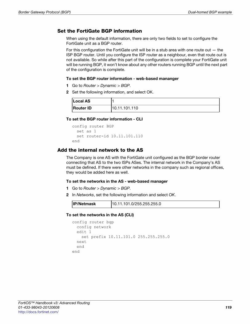
Border Gateway Protocol (BGP) Dual-homed BGP example
F
0
h
Set the FortiGate BGP informationWhen using the default information, there are only two fields to set to configure the
FortiGate unit as a BGP router.
For this configuration the FortiGate unit will be in a stub area with one route out — the
ISP BGP router. Until you configure the ISP router as a neighbour, even that route out is
not available. So while after this part of the configuration is complete your FortiGate unit
will be running BGP, it won’t know about any other routers running BGP until the next part
of the configuration is complete.
To set the BGP router information - web-based mananger
1 Go to Router > Dynamic > BGP.
2 Set the following information, and select OK.
To set the BGP router information - CLI
config router BGPset as 1set router-id 10.11.101.110
end
Add the internal network to the ASThe Company is one AS with the FortiGate unit configured as the BGP border router
connecting that AS to the two ISPs ASes. The internal network in the Company’s AS
must be defined. If there were other networks in the company such as regional offices,
they would be added here as well.
To set the networks in the AS - web-based manager
1 Go to Router > Dynamic > BGP.
2 In Networks, set the following information and select OK.
To set the networks in the AS (CLI)
config router bgpconfig networkedit 1set prefix 10.11.101.0 255.255.255.0
nextend
end
Local AS 1
Router ID 10.11.101.110
IP/Netmask 10.11.101.0/255.255.255.0
ortiOS™ Handbook v3: Advanced Routing
1-433-98043-20120608 119
ttp://docs.fortinet.com/
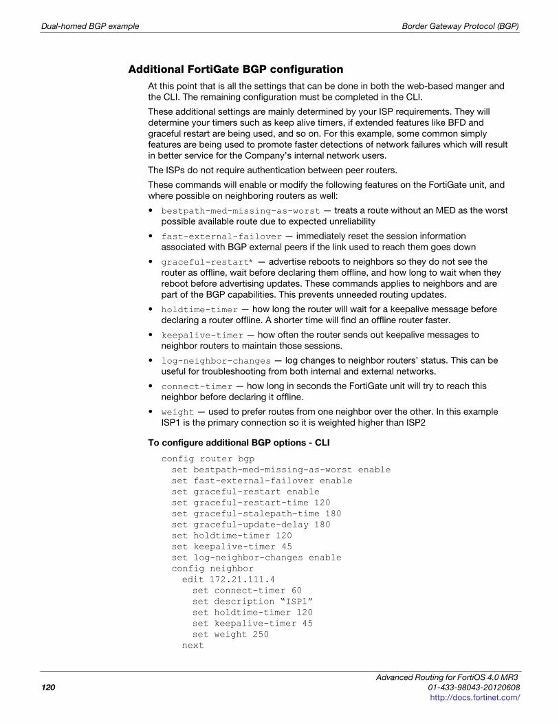
Dual-homed BGP example Border Gateway Protocol (BGP)
Additional FortiGate BGP configurationAt this point that is all the settings that can be done in both the web-based manger and
the CLI. The remaining configuration must be completed in the CLI.
These additional settings are mainly determined by your ISP requirements. They will
determine your timers such as keep alive timers, if extended features like BFD and
graceful restart are being used, and so on. For this example, some common simply
features are being used to promote faster detections of network failures which will result
in better service for the Company’s internal network users.
The ISPs do not require authentication between peer routers.
These commands will enable or modify the following features on the FortiGate unit, and
where possible on neighboring routers as well:
• bestpath-med-missing-as-worst — treats a route without an MED as the worst
possible available route due to expected unreliability
• fast-external-failover — immediately reset the session information
associated with BGP external peers if the link used to reach them goes down
• graceful-restart* — advertise reboots to neighbors so they do not see the
router as offline, wait before declaring them offline, and how long to wait when they
reboot before advertising updates. These commands applies to neighbors and are
part of the BGP capabilities. This prevents unneeded routing updates.
• holdtime-timer — how long the router will wait for a keepalive message before
declaring a router offline. A shorter time will find an offline router faster.
• keepalive-timer — how often the router sends out keepalive messages to
neighbor routers to maintain those sessions.
• log-neighbor-changes — log changes to neighbor routers’ status. This can be
useful for troubleshooting from both internal and external networks.
• connect-timer — how long in seconds the FortiGate unit will try to reach this
neighbor before declaring it offline.
• weight — used to prefer routes from one neighbor over the other. In this example
ISP1 is the primary connection so it is weighted higher than ISP2
To configure additional BGP options - CLI
config router bgpset bestpath-med-missing-as-worst enableset fast-external-failover enableset graceful-restart enableset graceful-restart-time 120 set graceful-stalepath-time 180set graceful-update-delay 180set holdtime-timer 120set keepalive-timer 45set log-neighbor-changes enableconfig neighboredit 172.21.111.4set connect-timer 60set description “ISP1”set holdtime-timer 120set keepalive-timer 45set weight 250
next
Advanced Routing for FortiOS 4.0 MR3
120 01-433-98043-20120608
http://docs.fortinet.com/
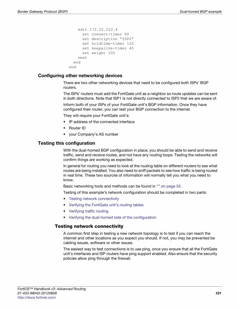
Border Gateway Protocol (BGP) Dual-homed BGP example
F
0
h
edit 172.22.222.4set connect-timer 60set description “ISP2”set holdtime-timer 120set keepalive-timer 45set weight 100
nextend
end
Configuring other networking devices
There are two other networking devices that need to be configured both ISPs’ BGP
routers.
The ISPs’ routers must add the FortiGate unit as a neighbor so route updates can be sent
in both directions. Note that ISP1 is not directly connected to ISP2 that we are aware of.
Inform both of your ISPs of your FortiGate unit’s BGP information. Once they have
configured their router, you can test your BGP connection to the internet.
They will require your FortiGate unit’s:
• IP address of the connected interface
• Router ID
• your Company’s AS number
Testing this configuration
With the dual-homed BGP configuration in place, you should be able to send and receive
traffic, send and receive routes, and not have any routing loops. Testing the networks will
confirm things are working as expected.
In general for routing you need to look at the routing table on different routers to see what
routes are being installed. You also need to sniff packets to see how traffic is being routed
in real time. These two sources of information will normally tell you what you need to
know.
Basic networking tools and methods can be found in “” on page 55.
Testing of this example’s network configuration should be completed in two parts:
• Testing network connectivity
• Verifying the FortiGate unit’s routing tables
• Verifying traffic routing
• Verifying the dual-homed side of the configuration
Testing network connectivityA common first step in testing a new network topology is to test if you can reach the
internet and other locations as you expect you should. If not, you may be prevented be
cabling issues, software or other issues.
The easiest way to test connections is to use ping, once you ensure that all the FortiGate
unit’s interfaces and ISP routers have ping support enabled. Also ensure that the security
policies allow ping through the firewall.
ortiOS™ Handbook v3: Advanced Routing
1-433-98043-20120608 121
ttp://docs.fortinet.com/
Dual-homed BGP example Border Gateway Protocol (BGP)
Connections to test in this example are the internal network to ISP1’s router or the
internet, and the same for ISP2. If you can connect on the external side of the Fortinet
unit, try to ping the internal network. Those three tests should prove your basic network
connections are working.
Verifying the FortiGate unit’s routing tablesThe FortiGate routing table contains the routes stored for future use. If you are expecting
certain routes to be there and they are not, that is a good indicator that your configuration
is not what you expected.
The CLI command get router info routing-table details will provide you
with every route’s routing protocol, destination address, gateway address, interface,
weighting, and if the address is directly connected or not.
If you want to limit the display to BGP routes only, use the CLI command get router info routing-table bgp. If there are no BGP routes in the routing table, nothing will
be displayed. In the CLI command you can replace BGP with static, or other routing
protocols to only display those routes.
If you want to see the contents of the routing information database (RIB), use the CLI
command get router info routing-table database. This will display the
incoming routes that may or may not make it into the routing table.
Verifying traffic routingTraffic may be reaching the internal network, but it may be using a different route than
you think to get there.
Use a browser to try and access the Internet.
If needed, allow traceroute and other diag ports to be opened until things are working
properly. Then remove access for them again.
Look for slow hops on the traceroute, or pings to a location, as they may indicate network
loops that need to be fixed.
Any locations that have an unresolved traceroute or ping must be examined and fixed.
Use network packet sniffing to ensure traffic is being routed as you expect.
Verifying the dual-homed side of the configurationSince there are two connections to the internet in this example, theoretically you can pull
the plug on one of the ISP connections, and all traffic will go through the other
connection. Alternately, you may choose to remove a default route to one ISP, remove
that ISP’s neighbor settings, or change the weightings to prefer other other ISP. These
alternate ways to test dual-homing do not change physical cabling, which may be
preferred in some situations.
If this does not work as expected, things to check include:
• default static routes — if these are wrong or don’t exist, the traffic can’t get out.
• BGP neighbor information — If the ISP router information is incorrect, the FortiGate
unit won’t be able to talk to it.
Once you have completed testing the network connectivity, turn off ping support on the
external interfaces for additional security.
Advanced Routing for FortiOS 4.0 MR3
122 01-433-98043-20120608
http://docs.fortinet.com/
Border Gateway Protocol (BGP) Redistributing and blocking routes in BGP
F
0
h
Redistributing and blocking routes in BGP
During normal BGP operation, peer routers redistribute routes from each other. However,
in some specific situations it may be best to not advertise routes from one peer for
various reasons. Some reasons may be the peer is redundant with another peer (they
share the same routes exactly), it might be unreliable in some way, or some other reason.
The FortiGate can also take routes it learns from other protocols and advertise them in
BGP, for example OSPF or RIP. If your Company hosts its own web or email servers,
external locations will require routes to your networks to reach those services.
In this example the Company has a internal networks in an OSPF area, and is connected
to a BGP AS and two BGP peers. Company goes through these two peers to reach the
Internet. However, Peer 1 routes will not be advertised to Peer 2. The Company internal
user and server networks are running OSPF, and will redistribute those routes to BGP so
external locations can reach the web and email servers.
This section includes the following topics:
• Network layout and assumptions
• General configuration steps
• Configuring the FortiGate unit
• Configuring other networking devices
• Testing this configuration
Network layout and assumptions
This section includes:
• Network layout
• Assumptions
Network layoutThe network layout for the BGP redistributing routes example involves the company
network being connected to two BGP peers as shown below. In this configuration the
FortiGate unit is the BGP border router between the Company AS, and the peer routers.
The components of the layout include:
• There is only one BGP AS in this example — AS 65001, shared by the FortiGate unit
and both peers.
• The Company’s FortiGate unit connects to the Internet through two BGP peers.
• The Company internal networks on the dmz interface of the FortiGate unit with an IP
of 10.11.201.0/24.
• The FortiGate units’ interfaces are connected as follows:
• port1 (dmz) has IP 10.11.201.110 and is the internal user and server network
• port2 (external1) has IP 172.21.111.4 and is connected to Peer 1’s network
• port3 (external2) has IP 172.22.222.4 and is connected to Peer 2’s network
• Peer 1 has IP 172.21.111.5, and Peer 2 has IP 172.22.222.5.
• OSPF Area 1 is configured on the dmz interface of the FortiGate unit, and is the
routing protocol used by the internal users and servers.
ortiOS™ Handbook v3: Advanced Routing
1-433-98043-20120608 123
ttp://docs.fortinet.com/
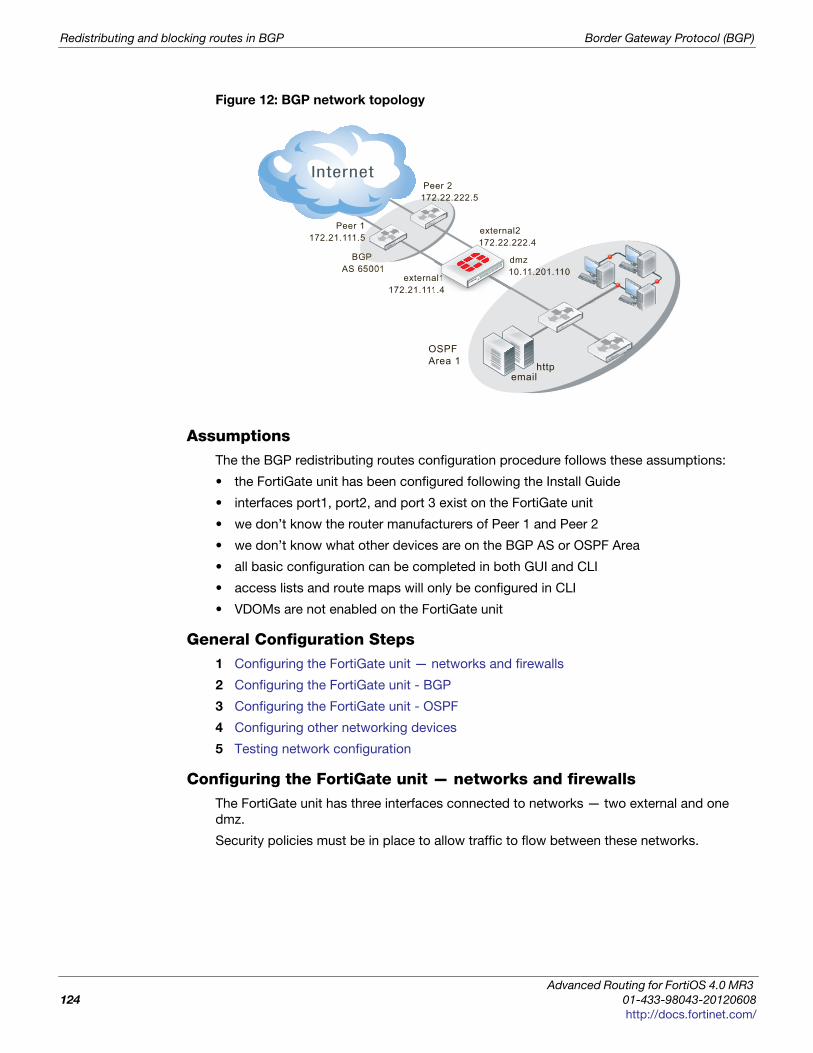
Redistributing and blocking routes in BGP Border Gateway Protocol (BGP)
Figure 12: BGP network topology
AssumptionsThe the BGP redistributing routes configuration procedure follows these assumptions:
• the FortiGate unit has been configured following the Install Guide
• interfaces port1, port2, and port 3 exist on the FortiGate unit
• we don’t know the router manufacturers of Peer 1 and Peer 2
• we don’t know what other devices are on the BGP AS or OSPF Area
• all basic configuration can be completed in both GUI and CLI
• access lists and route maps will only be configured in CLI
• VDOMs are not enabled on the FortiGate unit
General Configuration Steps1 Configuring the FortiGate unit — networks and firewalls
2 Configuring the FortiGate unit - BGP
3 Configuring the FortiGate unit - OSPF
4 Configuring other networking devices
5 Testing network configuration
Configuring the FortiGate unit — networks and firewallsThe FortiGate unit has three interfaces connected to networks — two external and one
dmz.
Security policies must be in place to allow traffic to flow between these networks.
external1172.21.111.4
httpemail
dmz 10.11.201.110
Peer 2 172.22.222.5
BGP AS 65001
OSPF Area 1
Peer 1172.21.111.5
external2 172.22.222.4
ala 11111111.44
dd11
Advanced Routing for FortiOS 4.0 MR3
124 01-433-98043-20120608
http://docs.fortinet.com/
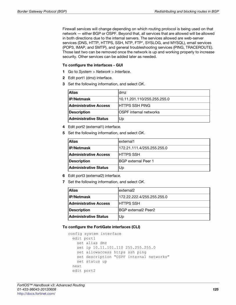
Border Gateway Protocol (BGP) Redistributing and blocking routes in BGP
F
0
h
Firewall services will change depending on which routing protocol is being used on that
network — either BGP or OSPF. Beyond that, all services that are allowed will be allowed
in both directions due to the internal servers. The services allowed are web-server
services (DNS, HTTP, HTTPS, SSH, NTP, FTP*, SYSLOG, and MYSQL), email services
(POP3, IMAP, and SMTP), and general troubleshooting services (PING, TRACEROUTE).
Those last two can be removed once the network is up and working properly to increase
security. Other services can be added later as needed.
To configure the interfaces - GUI
1 Go to System > Network > Interface.
2 Edit port1 (dmz) interface.
3 Set the following information, and select OK.
4 Edit port2 (external1) interface.
5 Set the following information, and select OK.
6 Edit port3 (external2) interface.
7 Set the following information, and select OK.
To configure the FortiGate interfaces (CLI)
config system interfaceedit port1set alias dmzset ip 10.11.101.110 255.255.255.0set allowaccess https ssh pingset description “OSPF internal networks”set status up
nextedit port2
Alias dmz
IP/Netmask 10.11.201.110/255.255.255.0
Administrative Access HTTPS SSH PING
Description OSPF internal networks
Administrative Status Up
Alias external1
IP/Netmask 172.21.111.4/255.255.255.0
Administrative Access HTTPS SSH
Description BGP external Peer 1
Administrative Status Up
Alias external2
IP/Netmask 172.22.222.4/255.255.255.0
Administrative Access HTTPS SSH
Description BGP external2 Peer2
Administrative Status Up
ortiOS™ Handbook v3: Advanced Routing
1-433-98043-20120608 125
ttp://docs.fortinet.com/
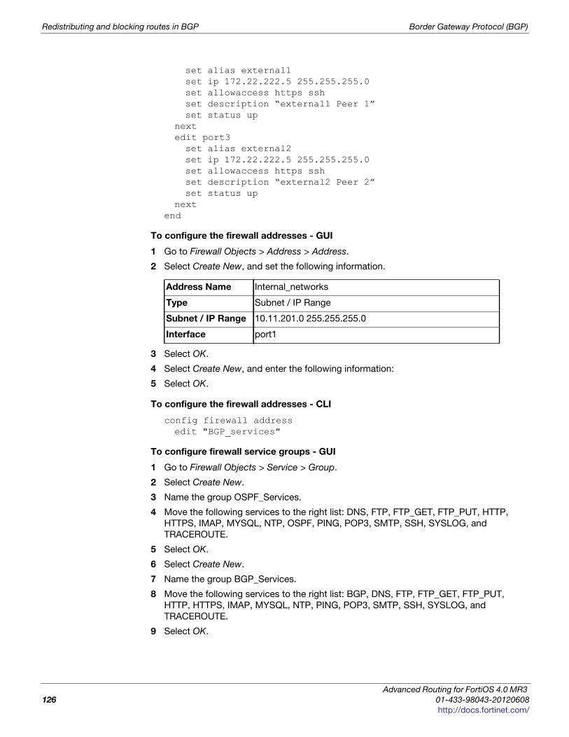
Redistributing and blocking routes in BGP Border Gateway Protocol (BGP)
set alias external1set ip 172.22.222.5 255.255.255.0set allowaccess https sshset description “external1 Peer 1”set status up
nextedit port3set alias external2set ip 172.22.222.5 255.255.255.0set allowaccess https sshset description “external2 Peer 2”set status up
nextend
To configure the firewall addresses - GUI
1 Go to Firewall Objects > Address > Address.
2 Select Create New, and set the following information.
3 Select OK.
4 Select Create New, and enter the following information:
5 Select OK.
To configure the firewall addresses - CLI
config firewall addressedit "BGP_services"
To configure firewall service groups - GUI
1 Go to Firewall Objects > Service > Group.
2 Select Create New.
3 Name the group OSPF_Services.
4 Move the following services to the right list: DNS, FTP, FTP_GET, FTP_PUT, HTTP,
HTTPS, IMAP, MYSQL, NTP, OSPF, PING, POP3, SMTP, SSH, SYSLOG, and
TRACEROUTE.
5 Select OK.
6 Select Create New.
7 Name the group BGP_Services.
8 Move the following services to the right list: BGP, DNS, FTP, FTP_GET, FTP_PUT,
HTTP, HTTPS, IMAP, MYSQL, NTP, PING, POP3, SMTP, SSH, SYSLOG, and
TRACEROUTE.
9 Select OK.
Address Name Internal_networks
Type Subnet / IP Range
Subnet / IP Range 10.11.201.0 255.255.255.0
Interface port1
Advanced Routing for FortiOS 4.0 MR3
126 01-433-98043-20120608
http://docs.fortinet.com/
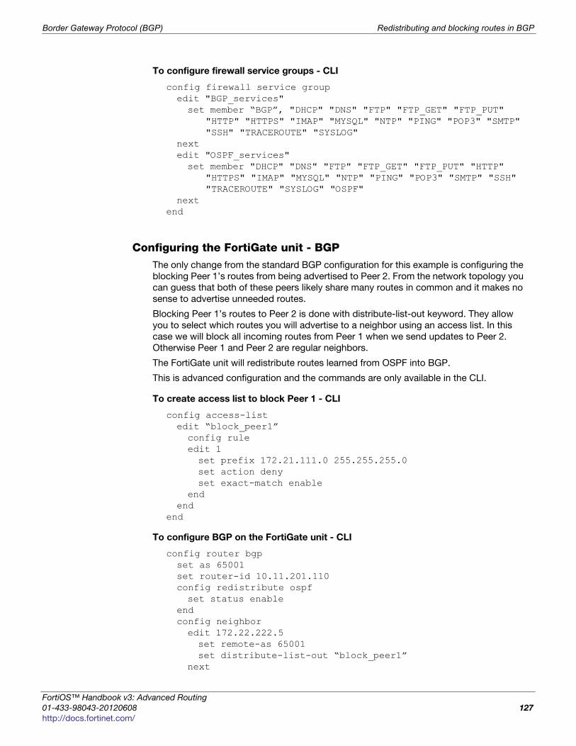
Border Gateway Protocol (BGP) Redistributing and blocking routes in BGP
F
0
h
To configure firewall service groups - CLI
config firewall service groupedit "BGP_services"set member “BGP”, "DHCP" "DNS" "FTP" "FTP_GET" "FTP_PUT"
"HTTP" "HTTPS" "IMAP" "MYSQL" "NTP" "PING" "POP3" "SMTP" "SSH" "TRACEROUTE" "SYSLOG"
nextedit "OSPF_services"set member "DHCP" "DNS" "FTP" "FTP_GET" "FTP_PUT" "HTTP"
"HTTPS" "IMAP" "MYSQL" "NTP" "PING" "POP3" "SMTP" "SSH" "TRACEROUTE" "SYSLOG" "OSPF"
nextend
Configuring the FortiGate unit - BGPThe only change from the standard BGP configuration for this example is configuring the
blocking Peer 1’s routes from being advertised to Peer 2. From the network topology you
can guess that both of these peers likely share many routes in common and it makes no
sense to advertise unneeded routes.
Blocking Peer 1’s routes to Peer 2 is done with distribute-list-out keyword. They allow
you to select which routes you will advertise to a neighbor using an access list. In this
case we will block all incoming routes from Peer 1 when we send updates to Peer 2.
Otherwise Peer 1 and Peer 2 are regular neighbors.
The FortiGate unit will redistribute routes learned from OSPF into BGP.
This is advanced configuration and the commands are only available in the CLI.
To create access list to block Peer 1 - CLI
config access-listedit “block_peer1”config ruleedit 1set prefix 172.21.111.0 255.255.255.0set action denyset exact-match enable
endend
end
To configure BGP on the FortiGate unit - CLI
config router bgpset as 65001set router-id 10.11.201.110config redistribute ospfset status enable
endconfig neighboredit 172.22.222.5set remote-as 65001set distribute-list-out “block_peer1”
next
ortiOS™ Handbook v3: Advanced Routing
1-433-98043-20120608 127
ttp://docs.fortinet.com/
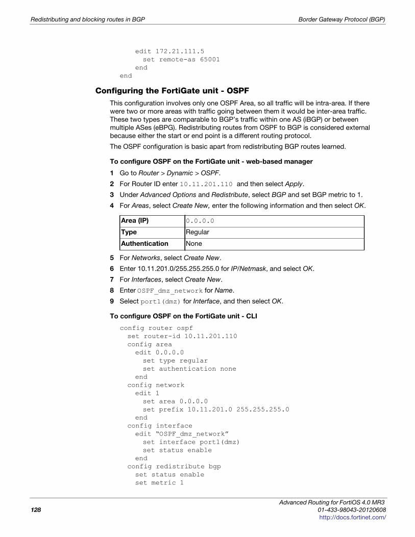
Redistributing and blocking routes in BGP Border Gateway Protocol (BGP)
edit 172.21.111.5set remote-as 65001
endend
Configuring the FortiGate unit - OSPFThis configuration involves only one OSPF Area, so all traffic will be intra-area. If there
were two or more areas with traffic going between them it would be inter-area traffic.
These two types are comparable to BGP’s traffic within one AS (iBGP) or between
multiple ASes (eBPG). Redistributing routes from OSPF to BGP is considered external
because either the start or end point is a different routing protocol.
The OSPF configuration is basic apart from redistributing BGP routes learned.
To configure OSPF on the FortiGate unit - web-based manager
1 Go to Router > Dynamic > OSPF.
2 For Router ID enter 10.11.201.110 and then select Apply.
3 Under Advanced Options and Redistribute, select BGP and set BGP metric to 1.
4 For Areas, select Create New, enter the following information and then select OK.
5 For Networks, select Create New.
6 Enter 10.11.201.0/255.255.255.0 for IP/Netmask, and select OK.
7 For Interfaces, select Create New.
8 Enter OSPF_dmz_network for Name.
9 Select port1(dmz) for Interface, and then select OK.
To configure OSPF on the FortiGate unit - CLI
config router ospfset router-id 10.11.201.110config areaedit 0.0.0.0set type regularset authentication none
endconfig networkedit 1set area 0.0.0.0set prefix 10.11.201.0 255.255.255.0
endconfig interfaceedit “OSPF_dmz_network”set interface port1(dmz)set status enable
endconfig redistribute bgpset status enableset metric 1
Area (IP) 0.0.0.0
Type Regular
Authentication None
Advanced Routing for FortiOS 4.0 MR3
128 01-433-98043-20120608
http://docs.fortinet.com/
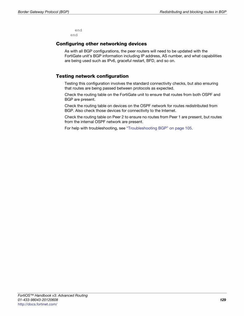
Border Gateway Protocol (BGP) Redistributing and blocking routes in BGP
F
0
h
endend
Configuring other networking devicesAs with all BGP configurations, the peer routers will need to be updated with the
FortiGate unit’s BGP information including IP address, AS number, and what capabilities
are being used such as IPv6, graceful restart, BFD, and so on.
Testing network configurationTesting this configuration involves the standard connectivity checks, but also ensuring
that routes are being passed between protocols as expected.
Check the routing table on the FortiGate unit to ensure that routes from both OSPF and
BGP are present.
Check the routing table on devices on the OSPF network for routes redistributed from
BGP. Also check those devices for connectivity to the Internet.
Check the routing table on Peer 2 to ensure no routes from Peer 1 are present, but routes
from the internal OSPF network are present.
For help with troubleshooting, see “Troubleshooting BGP” on page 105.
ortiOS™ Handbook v3: Advanced Routing
1-433-98043-20120608 129
ttp://docs.fortinet.com/

Redistributing and blocking routes in BGP Border Gateway Protocol (BGP)
Advanced Routing for FortiOS 4.0 MR3
130 01-433-98043-20120608
http://docs.fortinet.com/
F o r t i O S H a n d b o o k
F
0
h
Open Shortest Path First (OSPF)This section describes OSPF routing.
The following topics are included in this section:
• OSPF Background and concepts
• Troubleshooting OSPF
• OSPF routing examples
OSPF Background and concepts
This section includes:
• Background
• The parts and terminology of OSPF
• How OSPF works
Background
OSPF is a link-state interior routing protocol, that is widely used in large enterprise
organizations. It only routes packets within a single autonomous system (AS). This is
different from BGP as BGP can communicate between ASes.
The main benefit of OSPF is that it detects link failures in the network quickly and within
seconds has converged network traffic successfully without any networking loops. Also
OSPF has many features to control which routes are propagated and which are not,
maintaining smaller routing tables. OSPF can also provide better load-balancing on
external links than other interior routing protocols.
OSPF version 2 was defined in 1998 in RFC 2328. OSPF was designed to support
classless IP addressing, and variable subnet masks. This was a shortcoming of the earlier
RIP protocols.
Updates to OSPF version 2 are included in OSPF version 3 defined in 2008 in RFC 5340.
OSPF3 includes support for IPv6 addressing where previously OSPF2 only supports IPv4
addressing.
The parts and terminology of OSPF
Parts and terminology of OSPF includes:
• OSPF and IPv6
• Router ID
• Adjacency
• Designated router (DR) and backup router (BDR)
• Area
• Authentication
• Hello and dead intervals
ortiOS™ Handbook v3: Advanced Routing
1-435-99686-20120313 131
ttp://docs.fortinet.com/
OSPF Background and concepts Open Shortest Path First (OSPF)
OSPF and IPv6OSPF version 3 includes support for IPv6. Generally all IP addresses are in IPv6 format
instead of IPv4.
OSPF3 area numbers use the same 32-bit numbering system as OSPF2.
Router IDIn OSPF, each router has a unique 32-bit number called its Router ID. Often this 32-bit
number is written the same as a 32-bit IPv4 address would be written in dotted decimal
notation. However some brands of routers, such as Cisco routers, support a router ID
entered as an integer instead of an IP address.
It is a good idea to not use IP address in use on the router for the router ID number. The
router ID does not have to be a particular IP address on the router. By choosing a
different number, it will be harder to get confused which number you are looking at. A
good idea can be to use the as much of the area's number as possible. For example if
you have 15 routers in area 0.0.0.0 they could be numbered from 0.0.0.1 to 0.0.0.15. If
you have an area 1.1.1.1, then routers in that area could start at 1.1.1.10 for example.
You can manually set the router ID on your FortiGate unit.
To manually set an OSPF router ID of 0.0.1.1 - web-based manager
1 Go to Router > Dynamic > OSPF.
2 For Router ID, enter 0.0.1.1.
3 Select OK.
To manually set an OSPF router ID of 0.0.1.1 - CLI
config router ospfset router-id 0.0.1.1
end
AdjacencyIn an OSPF routing network, when an OSPF router boots up it sends out OSPF Hello
packets to find any neighbors, or routers that have access to the same network as the
router booting up. Once neighbors are discovered and Hello packets are exchanged,
updates are sent, and the Link State databases of both neighbors are synchronized. At
this point these neighbors are said to be adjacent.
For two OSPF routers to become neighbors, the following conditions must be met.
• The subnet mask used on both routers must be the same subnet.
• The subnet number derived using the subnet mask and each router's interface IP
address must match.
• The Hello interval & The Dead interval must match.
• The routers must have the same OSPF area ID. If they are in different areas, they are
not neighbors.
• If authentication is used, they must pass authentication checks.
If any of these parameters are different between the two routers, the routers do not
become OSPF neighbors and cannot be adjacent. If the routers become neighbors, they
are adjacent.
Advanced Routing for FortiOS 4.0 MR3
132 01-435-99686-20120313
http://docs.fortinet.com/
Open Shortest Path First (OSPF) OSPF Background and concepts
F
0
h
Adjacency and neighborsNeighbor routers can be in a Two-Way state, and not be adjacent. Adjacent routers
normally have a neighbour state of FULL. Neighbors only exchange Hello packets, and
do not exchange routing updates. Adjacent routers exchange LSAs (LSDB information)
as well as Hello packets. A good example of an adjacent pair of routers is the DR and
BDR.
You can check on the state of an OSPF neighbor using the CLI command get router info ospf neighbor all. See “Checking the state of OSPF neighbors” on page 144.
Why adjacency is importantIt is important to have adjacent pairs of routers in the OSPF routing domain because
routing protocol packets are only passed between adjacent routers. This means
adjacency is required for two OSPF routers to exchange routes. If there is no adjacency
between two routers, such as one on the 172.20.120.0 network and another on the
10.11.101.0 network, the routers do not exchange routes. This makes sense because if
all OSPF routers on the OSPF domain exchanged updates it would flood the network.
Also its better for updates to progress through adjacent routers to ensure there are no
outages along the way. Otherwise updates could skip over routers that are potentially
offline, causing longer routing outages and delays while the OSPF domain learns of this
outage later on.
If the OSPF network has multiple border routers and multiple connections to external
networks, the designated router (DR) determines which router pairs become adjacent.
The DR can accomplish this because it maintains the complete topology of the OSPF
domain, including which router pairs are adjacent. The BDR also has this information in
case the DR goes offline.
Designated router (DR) and backup router (BDR)In OSPF a router can have a number of different roles to play.
A designated router (DR) is the designated broadcasting router interface for an AS. It
looks after all the initial contact and other routing administration traffic. Having only one
router do all this greatly reduces the network traffic and collisions.
If something happens and the designated router goes offline, the backup designated
router (BDR) takes over. An OSPF FortiGate unit interface can become either a DR or
BDR. Both the DR and the BDR cover the same area, and are elected at the same time.
The election process doesn’t have many rules, but the exceptions can become complex.
BenefitsThe OSPF concept of the designated router is a big step above RIP. With all RIP routers
doing their own updates all the time, RIP suffers from frequent and sometimes
unnecessary updates that can slow down your network. With OSPF, not only do routing
changes only happen when a link-state changes instead of any tiny change to the routing
table, but the designated router reduces this overhead traffic even more.
However, smaller network topologies may only have a couple routers besides the
designated router. This may seem excessive, but it maintains the proper OSPF form and
it will still reduce the administration traffic but to a lesser extent than on a large network.
Also your network topology is ready for when you expand your network.
ortiOS™ Handbook v3: Advanced Routing
1-435-99686-20120313 133
ttp://docs.fortinet.com/
OSPF Background and concepts Open Shortest Path First (OSPF)
DR and BDR electionAn election chooses the DR and BDR from all the available routers. The election is
primarily based on the priority setting of the routers—the highest priority becomes the
DR, and the second highest becomes BDR. To resolve any ties, the router with the
highest router ID wins. For example 192.168.0.1 would win over 10.1.1.2.
The router priority can vary from 0 to 255, but at 0 a router will never become a DR or
BDR. If a router with a higher priority comes on line after the election, it must wait until
after the DR and BDR go offline before it would become the DR.
If the original DR goes offline, but then is available when the BDR goes offline later on, the
original DR will be promoted back to DR without an election leaving the new BDR as it is.
With your FortiGate unit, to configure the port1 interface to be a potential OSPF
designated router or backup designed router called ospf_DR on the network, you need
to raise the priority of the router to a very high number such as 250 out of 255. This will
ensure the interface has a chance to be a DR, but will not guarantee that it will be one.
Give the interface a low numbered IP address—such as 10.1.1.1 instead of
192.168.1.1—to help ensure it becomes a DR, but that is not part of this example. Enter
the following command:
config router ospfconfig ospf-interfaceedit “ospf_DR”set priority 250
endend
Area An OSPF area is a smaller part of the larger OSPF AS. Areas are used to limit the link-
state updates that are sent out. The flooding used for these updates would overwhelm a
large network, so it is divided into these smaller areas for manageability.
Within an area if there are two or more routers that are viable, there will always be a
designated router (DR) and a backup DR (BDR). For more on these router roles, see
“Designated router (DR) and backup router (BDR)” on page 133.
Defining a private OSPF area, involves:
• assigning a 32-bit number to the area that is unique on your network
• defining the characteristics of one or more OSPF areas
• creating associations between the OSPF areas that you defined and the local
networks to include in the OSPF area
• if required, adjusting the settings of OSPF-enabled interfaces.
If you are using the web-based manager to perform these tasks, follow the procedures
summarized below.
FortiGate units support the four main types of OSPF area:
• Backbone area
• NSSA
• Stub area
IPv6 OSPF area numbers use the same 32-bit number notation as IPv4 OSPF
Advanced Routing for FortiOS 4.0 MR3
134 01-435-99686-20120313
http://docs.fortinet.com/
Open Shortest Path First (OSPF) OSPF Background and concepts
F
0
h
• Regular area
Backbone areaEvery OSPF network has at least one AS, and every OSPF network has a backbone area.
The backbone is the main area, or possibly the only area. All other OSPF areas are
connected to a backbone area. This means if two areas want to pass routing information
back and forth, that routing information will go through the backbone on its way between
those areas. For this reason the backbone not only has to connect to all other areas in the
network, but also be uninterrupted to be able to pass traffic to all points of the network.
The backbone area is referred to as area 0 because it has an IP address of 0.0.0.0.
Stub areaA stub area is an OSPF area that receives no outside routes advertised into it, and all
routing in it is based on a default route. This essentially isolates it from outside areas.
Stub areas are useful for small networks that are part of a larger organization, especially if
the networking equipment can’t handle routing large amounts of traffic passing through,
or there are other reasons to prevent outside traffic, such as security. For example most
organizations don’t want their accounting department to be the center of their network
with everyone’s traffic passing through there. It would increase the security risks, slow
down their network, and it generally doesn’t make sense.
A variation on the stub area is the totally stubby area. It is a stub area that does not allow
summarized routes.
NSSAA not-so-stubby-area (NSSA) is a stub area that allows for external routes to be injected
into it. While it still does not allow routes from external areas, it is not limited to only using
he default route for internal routing.
Regular areaA regular area is what all the other ASes are, all the non-backbone, non-stub, non-NSSA
areas. A regular area generally has a connection to the backbone, does receive
advertisements of outside routes, and does not have an area number of 0.0.0.0.
AuthenticationIn the OSPF packet header are two authentication related fields —AuType, and
Authentication.
All OSPF packet traffic is authenticated. Multiple types of authentication are supported in
OSPFv2. However in OSPFv3, there is no authentication built-in but it is assumed that
IPsec will be used for authentication instead.
Packets that fail authentication are discarded.
Null authenticationNull authentication indicates there is no authentication being used. In this case the 16-
byte Authentication field is not checked, and can be any value. However checksumming
is still used to locate errors. On your FortiGate this is the none option for authentication.
ortiOS™ Handbook v3: Advanced Routing
1-435-99686-20120313 135
ttp://docs.fortinet.com/
OSPF Background and concepts Open Shortest Path First (OSPF)
Simple Password authenticationSimple password refers to a standard plain text string of characters. The same password
is used for all transactions on a network. The main use of this type of authentication is to
prevent routers from accidently joining the network. Simple password authentication is
vulnerable to many forms of attack, and is not recommended as a secure form of
authentication.
Cryptographic authenticationCryptographic authentication involves the use of a shared secret key to authenticate all
router traffic on a network. The key is never sent over the network in the clear—a packet
is sent and a condensed and encrypted form of the packet is appended to the end of the
packet. A non-repeating sequence number is included in the OSPF packet to protect
against replay attacks that could try to use already sent packets to disrupt the network.
When a packet is accepted as authentic the authentication sequence number is set to
the packet sequence number. If a replay attack is attempted, the packet sent will be out
of sequence and ignored.
Your FortiGate unit supports all three levels of authentication through the authentication
keyword associated with creating an OSPF interface .
For example to create an OSPF interface called Accounting on the port1 interface that
is a broadcast interface, has a hello interval of 10 seconds, has a dead interval of 40
seconds, uses text authentication (simple password) with a password of “ospf_test”,
enter the command:
config router ospfconfig ospf-interfaceedit Accountingset interface port1set network-type broadcastset hello-interval 10set dead-interval 40set authentication textset authentication-key “ospf_test”
endend
Hello and dead intervalsThe OSPF Hello protocol is used to discover and maintain communications with
neighboring routers.
Hello packets are sent out at a regular interval for this purpose. The DR sends out the
Hello packets. In a broadcast network, the multicast address of 224.0.0.5 is used to send
out Hello packets. New routers on the network listen for and reply to these packets to join
the OSPF area. If a new router never receives a Hello packet, other routers will not know
it is there and will not communicate with it. However, once a new router is discovered the
DR adds it to the list of routers in that area and it is integrated into the routing
calculations.
Dead interval is the time it takes when a router doesn’t respond before it is declared
dead, or offline. If this interval is too short routers will be declared offline when they aren’t
and the link-state updates will happen more than they need to. If the dead interval is too
long, it will slow down network traffic while that router it attempted to be contacted when
it is already offline.
Advanced Routing for FortiOS 4.0 MR3
136 01-435-99686-20120313
http://docs.fortinet.com/
Open Shortest Path First (OSPF) OSPF Background and concepts
F
0
h
Access ListsAccess lists are filters used by FortiGate unit OSPF routing. An access list provides a list
of IP addresses and the action to take for them — essentially an access list makes it easy
to group addresses that will be treated the same into the same group, independent of
their subnets or other matching qualities. You add a rule for each address or subnet that
you want to include, specifying the action to take for it. For example if you wanted all
traffic from one department to be routed a particular way, even in different buildings, you
can add all the addresses to an access list and then handle that list all at once.
Each rule in an access list consists of a prefix (IP address and netmask), the action to
take for this prefix (permit or deny), and whether to match the prefix exactly or to match
the prefix and any more specific prefix.
The FortiGate unit attempts to match a packet against the rules in an access list starting
at the top of the list. If it finds a match for the prefix, it takes the action specified for that
prefix. If no match is found the default action is deny.
Access lists greatly speed up configuration and network management. When there is a
problem, you can check each list instead of individual addresses. Also its easier to
troubleshoot since if all addresses on one list have problems, it eliminates many possible
causes right away.
If you are using the OSPF+ IPv6 protocols you will need to use access-list6, the IPv6
version of access list. The only difference is that access-list6 uses IPv6 addresses.
For example, if you want to create an access list called test_list that only allows an
exact match of 10.10.10.10 and 11.11.11.11, enter the command:
config router access-listedit test_listconfig rule edit 1set prefix 10.10.10.10 255.255.255.255set action allowset exact-match enable
nextedit 2set prefix 11.11.11.11 255.255.255.255set action allowset exact-match enable
endend
Another example is if you want to deny ranges of addresses in IPv6 that start with the
IPv6 equivalents of 10.10.10.10 and 11.11.11.11, enter the command access-list6 as
follows:
config router access-list6edit test_list_ip6config ruleedit 1set prefix6 2002:A0A:A0A:0:0:0:0:0:/48set action deny
nextedit 2set prefix6 2002:B0B:B0B:0:0:0:0:0/48set action deny
end
ortiOS™ Handbook v3: Advanced Routing
1-435-99686-20120313 137
ttp://docs.fortinet.com/
OSPF Background and concepts Open Shortest Path First (OSPF)
To use an access_list, you must call it from a routing protocol such as RIP. The following
example uses the access_list from the earlier example called test_list to match routes
coming in on the port1 interface. When there is a match, it will add 3 to the hop count
metric for those routes to artificially increase. Enter the following command:
config router ospfconfig distribute-listedit 5set access-list test_listset protocol connected
end
If you are setting a prefix of 128.0.0.0, use the format 128.0.0.0/1. The default route,
0.0.0.0/0 can not be exactly matched with an access-list. A prefix-list must be used for
this purpose
How OSPF works
An OSPF network one or more areas. An OSPF area is typically divided into logical areas
linked by Area Border Routers. A group of contiguous networks form an area. An Area
Border Router (ABR) links one or more areas to the OSPF network backbone (area ID 0).
See “Area border router (ABR)” on page 53.
OSPF is an interior routing protocol. It includes a backbone AS, and possibly additional
ASes. The DR and BDR are elected from potential routers with the highest priorities. The
DR handles much of the administration to lower the network traffic required. New routers
are discovered through hello packets sent from the DR using the multicast address of
224.0.0.5. If the DR goes offline at any time, the BDR has a complete table of routes that
is uses when it takes over as the DR router.
OSPF does not use UDP or TCP, but is encapsulated directly in IP datagrams as protocol
89. This is in contrast to RIP, or BGP. OSPF handles its own error detection and correction
functions.
The OSPF protocol, when running on IPv4, can operate securely between routers,
optionally using a variety of authentication methods to allow only trusted routers to
participate in routing. OSPFv3, running on IPv6, no longer supports protocol-internal
authentication. Instead, it relies on IPv6 protocol security (IPsec).
Other important parts of how OSPF works includes:
• OSPF router discovery
• How OSPF works on FortiGate units
• External routes
• Link-state Database (LSDB) and route updates
• OSPF packets
OSPF router discoveryOSPF-enabled routers generate Link-State Advertisements (LSA) and send them to their
neighbors whenever the status of a neighbor changes or a new neighbor comes online.
As long as the OSPF network is stable, LSAs between OSPF neighbors do not occur. An
LSA identifies the interfaces of all OSPF-enabled routers in an area, and provides
information that enables OSPF-enabled routers to select the shortest path to a
destination. All LSA exchanges between OSPF-enabled routers are authenticated.
When a network of OSPF routers comes online, the follow steps occur.
1 When OSPF routers come online, they send out Hello packets to find other OSPF
routers on their network segment.
Advanced Routing for FortiOS 4.0 MR3
138 01-435-99686-20120313
http://docs.fortinet.com/
Open Shortest Path First (OSPF) OSPF Background and concepts
F
0
h
2 When they discover other routers on their network segment, generally they become
adjacent. Adjacent routers can exchange routing updates. See “Adjacency” on
page 132.
3 A DR and BDR are elected from the available routers using priority settings, and router
ID. See “Designated router (DR) and backup router (BDR)” on page 133, and “DR and
BDR election issues” on page 145.
4 Link state updates are sent between adjacent routers to map the topology of the
OSPF area.
5 Once complete, the DR floods the network with the updates to ensure all OSPF
routers in the area have the same OSPF route database. After the initial update, there
are very few required updates if the network is stable.
How OSPF works on FortiGate unitsWhen a FortiGate unit interface is connected to an OSPF area, that unit can participate in
OSPF communications. FortiGate units use the OSPF Hello protocol to acquire neighbors
in an area. A neighbor is any router that is directly connected to the same area as the
FortiGate unit, and ideally is adjacent with a state of Full. After initial contact, the
FortiGate unit exchanges Hello packets with its OSPF neighbors regularly to confirm that
the neighbors can be reached.
The number of routes that a FortiGate unit can learn through OSPF depends on the
network topology. A single unit can support tens of thousands of routes if the OSPF
network is configured properly.
External routesOSPF is an internal routing protocol. OSPF external routes are routes with the destination
of the connection using a routing protocol other than OSPF. OSPF handles external
routes by adjusting the cost of the route to include the cost of the other routing protocol.
There are two methods of calculating this cost, used for OSPF E1 and OSPF E2.
OSPF external1 (E1) In OSPF E1 the destination is outside of the OSPF domain. This requires a different
metric to be used beyond the normal OSPF metrics. The new metric of a redistributed
route is calculated by adding the external cost and the OSPF cost together.
OSPF external2 (E2)OSPF E2 is the default external type when routes are redistributed outside of OSPF.
OSPF E2 is similar to E1, except in this case, the metric of the redistributed route is
equivalent to the external cost only, expressed as an OSPF cost. Dropping the OSPF
portion can be useful in a number of situations, on border routers that have no OSPF
portion for example or where the OSPF routing cost is negligible compared to the
external routing cost.
Comparing E1 and E2The best way to understand OSPF E1 and E2 routes is to check routing tables on OSPF
routers. If you look at the routes on an OSPF border router, the redistributed routes will
have an associated cost that represents only the external route, as there is no OSPF cost
to the route due to it already being on the edge of the OSPF domain. However, if you look
at that same route on a different OSPF router inside the OSPF routing domain, it will have
a higher associated cost - essentially the external cost plus the cost over the OSPF
domain to that border router. The border router uses OSPF E2, where the internal OSPF
router uses OSPF E2 for the same route.
ortiOS™ Handbook v3: Advanced Routing
1-435-99686-20120313 139
ttp://docs.fortinet.com/
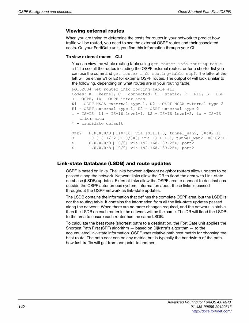
OSPF Background and concepts Open Shortest Path First (OSPF)
Viewing external routesWhen you are trying to determine the costs for routes in your network to predict how
traffic will be routed, you need to see the external OSPF routes and their associated
costs. On your FortiGate unit, you find this information through your CLI.
To view external routes - CLI
You can view the whole routing table using get router info routing-table all to see all the routes including the OSPF external routes, or for a shorter list you
can use the command get router info routing-table ospf. The letter at the
left will be either E1 or E2 for external OSPF routes. The output of will look similar to
the following, depending on what routes are in your routing table.
FGT620B# get router info routing-table allCodes: K - kernel, C - connected, S - static, R - RIP, B - BGPO - OSPF, IA - OSPF inter areaN1 - OSPF NSSA external type 1, N2 - OSPF NSSA external type 2E1 - OSPF external type 1, E2 - OSPF external type 2i - IS-IS, L1 - IS-IS level-1, L2 - IS-IS level-2, ia - IS-IS
inter area* - candidate default
O*E2 0.0.0.0/0 [110/10] via 10.1.1.3, tunnel_wan2, 00:02:11O 10.0.0.1/32 [110/300] via 10.1.1.3, tunnel_wan2, 00:02:11S 0.0.0.0/0 [10/0] via 192.168.183.254, port2S 1.0.0.0/8 [10/0] via 192.168.183.254, port2
Link-state Database (LSDB) and route updatesOSPF is based on links. The links between adjacent neighbor routers allow updates to be
passed along the network. Network links allow the DR to flood the area with Link-state
database (LSDB) updates. External links allow the OSPF area to connect to destinations
outside the OSPF autonomous system. Information about these links is passed
throughout the OSPF network as link-state updates.
The LSDB contains the information that defines the complete OSPF area, but the LSDB is
not the routing table. It contains the information from all the link-state updates passed
along the network. When there are no more changes required, and the network is stable
then the LSDB on each router in the network will be the same. The DR will flood the LSDB
to the area to ensure each router has the same LSDB.
To calculate the best route (shortest path) to a destination, the FortiGate unit applies the
Shortest Path First (SPF) algorithm — based on Dijkstra’s algorithm — to the
accumulated link-state information. OSPF uses relative path cost metric for choosing the
best route. The path cost can be any metric, but is typically the bandwidth of the path—
how fast traffic will get from one point to another.
Advanced Routing for FortiOS 4.0 MR3
140 01-435-99686-20120313
http://docs.fortinet.com/
Open Shortest Path First (OSPF) OSPF Background and concepts
F
0
h
The path cost, similar to “distance” for RIP, imposes a penalty on the outgoing direction
of a FortiGate unit interface. The path cost of a route is calculated by adding together all
of the costs associated with the outgoing interfaces along the path to the destination.
The lowest overall path cost indicates the best route, and generally the fastest route.
Some brands of OSPF routers, such as Cisco, implement cost as a direct result of
bandwidth between the routers. Generally this is a good cost metric because larger
bandwidth means more traffic can travel without slowing down. To achieve this type of
cost metric on FortiGate units, you need to set the cost for each interface manually in the
CLI.
The FortiGate unit dynamically updates its routing table based on the results of the SPF
calculation to ensure that an OSPF packet will be routed using the shortest path to its
destination. Depending on the network topology, the entries in the FortiGate unit routing
table may include:
• the addresses of networks in the local OSPF area (to which packets are sent directly)
• routes to OSPF area border routers (to which packets destined for another area are
sent)
• if the network contains OSPF areas and non-OSPF domains, routes to area boundary
routers, which reside on the OSPF network backbone and are configured to forward
packets to destinations outside the OSPF AS.
OSPF Route updatesOnce the OSPF domain is established, there should be few updates required on a stable
network. When updates occur and a decision is required concerning a new route, this is
the general procedure.
1 Our router gets a new route, and needs to decide if it should go in the routing table.
2 The router has an up to date LSDB of the entire area, containing information about
each router, the next hop to it, and most importantly the cost to get there.
3 Our router, turns the LSDB into a shortest path first (SPF) tree using Dijkstra’s
algorithm. It doesn’t matter if there is more than one path to a router on the network,
the SPF tree only cares about the shortest path to that router.
4 Once the SPF tree has been created, and shows the shortest paths to all the OSPF
routers on the network, the work is done. If the new route is the best route, it will be
part of that tree. If it is not the shortest route, it will not be included in the LSDB.
5 If there has been a change from the initial LSDB to the new SPF tree, a link state
update will be sent out to let the other routers know about the change so they can
update their LSDBs as well. This is vital since all routers on the OSPF area must have
the same LSDB.
6 If there was no change between the LSDB and the SPF tree, no action is taken.
The inter-area routes may not be calculated when a Cisco type ABR has no fully
adjacent neighbor in the backbone area. In this situation, the router considers summary-
LSAs from all Actively summary-LSAs from all Actively Attached areas (RFC 3509).
ortiOS™ Handbook v3: Advanced Routing
1-435-99686-20120313 141
ttp://docs.fortinet.com/
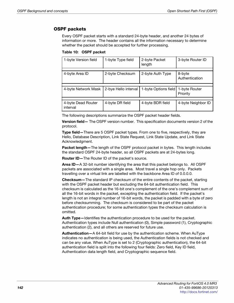
OSPF Background and concepts Open Shortest Path First (OSPF)
OSPF packetsEvery OSPF packet starts with a standard 24-byte header, and another 24 bytes of
information or more. The header contains all the information necessary to determine
whether the packet should be accepted for further processing.
The following descriptions summarize the OSPF packet header fields.
Version field— The OSPF version number. This specification documents version 2 of the
protocol.
Type field—There are 5 OSPF packet types. From one to five, respectively, they are
Hello, Database Description, Link State Request, Link State Update, and Link State
Acknowledgment.
Packet length—The length of the OSPF protocol packet in bytes. This length includes
the standard OSPF 24-byte header, so all OSPF packets are at 24-bytes long.
Router ID—The Router ID of the packet's source.
Area ID—A 32-bit number identifying the area that this packet belongs to. All OSPF
packets are associated with a single area. Most travel a single hop only. Packets
travelling over a virtual link are labelled with the backbone Area ID of 0.0.0.0.
Checksum—The standard IP checksum of the entire contents of the packet, starting
with the OSPF packet header but excluding the 64-bit authentication field. This
checksum is calculated as the 16-bit one's complement of the one's complement sum of
all the 16-bit words in the packet, excepting the authentication field. If the packet's
length is not an integral number of 16-bit words, the packet is padded with a byte of zero
before checksumming. The checksum is considered to be part of the packet
authentication procedure; for some authentication types the checksum calculation is
omitted.
Auth Type—Identifies the authentication procedure to be used for the packet.
Authentication types include Null authentication (0), Simple password (1), Cryptographic
authentication (2), and all others are reserved for future use.
Authentication—A 64-bit field for use by the authentication scheme. When AuType
indicates no authentication is being used, the Authentication fields is not checked and
can be any value. When AuType is set to 2 (Cryptographic authentication), the 64-bit
authentication field is split into the following four fields: Zero field, Key ID field,
Authentication data length field, and Cryptographic sequence field.
Table 10: OSPF packet
1-byte Version field 1-byte Type field 2-byte Packet
length
3-byte Router ID
4-byte Area ID 2-byte Checksum 2-byte Auth Type 8-byte
Authentication
4-byte Network Mask 2-bye Hello interval 1-byte Options field 1-byte Router
Priority
4-byte Dead Router
interval
4-byte DR field 4-byte BDR field 4-byte Neighbor ID
Advanced Routing for FortiOS 4.0 MR3
142 01-435-99686-20120313
http://docs.fortinet.com/
Open Shortest Path First (OSPF) Troubleshooting OSPF
F
0
h
The Key ID field indicates the key and algorithm used to create the message digest
appended to the packet. The authentication data length field indicates how many bytes
long the message digest is, and the cryptographic sequence number is at non-
decreasing number that is set when the packet is received and authenticated to prevent
replay attacks.
Network Mask—The subnet where this packet is valid.
Hello interval—The period of time between sending out Hello packets. See “Hello and
dead intervals” on page 136.
Options field— The OSPF protocol defines several optional capabilities. A router
indicates the optional capabilities that it supports in its OSPF Hello packets, Database
Description packets and in its LSAs. This enables routers supporting a mix of optional
capabilities to coexist in a single Autonomous System.
Router priority—The priority between 0 and 255 that determines which routers become
the DR and BDR. See “Designated router (DR) and backup router (BDR)” on page 133.
Dead router interval—The period of time when there is no response from a router before it
is declared dead. See “Hello and dead intervals” on page 136.
DR and BDR fields—The DR and BDR fields each list the router that fills that role on this
network, generally the routers with the highest priorities. See “Designated router (DR) and
backup router (BDR)” on page 133.
Neighbor ID—The ID number of a neighboring router. This ID is used to discover new
routers and respond to them.
Troubleshooting OSPF
As with other dynamic routing protocols, OSPF has some issues that may need
troubleshooting from time to time. For basic troubleshooting, see the FortiOS Handbook
Troubleshooting chapter.
The more common issues include:
• Clearing OSPF routes from the routing table
• Checking the state of OSPF neighbors
• Passive interface problems
• Timer problems
• Authentication issues
• DR and BDR election issues
Clearing OSPF routes from the routing table
If you think the wrong route has been added to your routing table and you want to check
it out, you first have to remove that route from your table before seeing if it is added back
in or not. You can clear all or some OSPF neighbor connections (sessions) using the
exec router clear OSPF command. The exec router clear command is much more
limiting for OSPF than it is for BGP. See “Clearing routing table entries” on page 105.
For example, if you have routes in the OSPF routing table and you want to clear the
specific route to IP address 10.10.10.1, you will have to clear all the OSPF entries. Enter
the command:
FGT# exec router clear ospf process
ortiOS™ Handbook v3: Advanced Routing
1-435-99686-20120313 143
ttp://docs.fortinet.com/
Troubleshooting OSPF Open Shortest Path First (OSPF)
Checking the state of OSPF neighbors
In OSPF each router sends out link state advertisements to find other routers on its
network segment, and to create adjacencies with some of those routers. This is important
because routing updates are only passed between adjacent routers. If two routers you
believe to be adjacent are not, that can be the source of routing failures.
To identify this problem, you need to check the state of the OSPF neighbors of your
FortiGate unit. Use the CLI command get router info ospf neighbor all to see
all the neighbors for your FortiGate unit. You will see output in the form of:
FGT1 # get router info ospf neighborOSPF process 0:Neighbor ID Pri State Dead Time Address Interface10.0.0.2 1 Full/ - 00:00:39 10.1.1.2 tunnel_wan110.0.0.2 1 Full/ - 00:00:34 10.1.1.4 tunnel_wan2
The important information here is the State column. Any neighbors that are not adjacent
to your FortiGate unit will be reported in this column as something other than Full. If the
state is Down, that router is offline.
Passive interface problems
A passive OSPF interface doesn’t send out any updates. This means it can’t be a DR,
BDR, or an area border router among other things. It will depend on other neighbor
routers to update its link-state table.
Passive interfaces can cause problems when they aren’t receiving the routing updates
you expect from their neighbors. This will result in the passive OSPF FortiGate unit
interface having an incomplete or out of date link-state database, and it will not be able to
properly route its traffic. It is possible that the passive interface is causing a hole in the
network where no routers are passing updates to each other, however this is a rare
situation.
If a passive interface is causing problems, there are some easy methods to determine it is
the cause. The easiest method is to make it an active interface, and if the issues
disappear that was the cause. Another method is to examine the OSPF routing table and
related information to see if it is incomplete compared to other neighbor routers. If this is
the case.
If you cannot make the interface active for some reason, you will have to change your
network to fix the “hole” by adding more routers, or changing the relationship between
the passive router’s neighbors to provide better coverage.
Timer problems
A timer mismatch is when two routers have different values set for the same timer. For
example if one router declares a router dead after 45 seconds and another waits for 4
minutes that difference in time will result in those two routers being out of synch for that
period of time—one will still see that offline router as being online.
The easiest method to check the timers is to check the configuration on each router.
Another method is to sniff some packets, and read the timer values in the packets
themselves from different routers. Each packet contains the hello interval, and dead
interval periods, so you can compare them easily enough.
Advanced Routing for FortiOS 4.0 MR3
144 01-435-99686-20120313
http://docs.fortinet.com/
Open Shortest Path First (OSPF) OSPF routing examples
F
0
h
Bi-directional Forwarding Detection (BFD)
Bi-directional Forwarding Detection (BFD) is a protocol used to quickly locate hardware
failures in the network. Routers running BFD communicate with each other, and if a timer
runs out on a connection then that router is declared down. BFD then communicates this
information to the routing protocol and the routing information is updated.
Authentication issues
OSPF has a number of authentication methods you can choose from. You may encounter
problems with routers not authenticating as you expect. This will likely appear simply as
one or more routers that have a blind spot in their routing - they won’t acknowledge a
router. This can be a problem if that router connects areas to the backbone as it will
appear to be offline and unusable.
To confirm this is the issue, the easiest method is to turn off authentication on the
neighboring routers. With no authentication between any routers, everything should flow
normally.
Another method to confirm that authentication is the problem is to sniff packets, and look
at their contents. The authentication type and password are right in the packets which
makes it easy to confirm they are what you expect during real time. Its possible one or
more routers is not configured as you expect and may be using the wrong authentication.
This method is especially useful if there are a group of routers with these problems—it
may only be one router causing the problem that is seen in multiple routers.
Once you have confirmed the problem is authentication related, you can decide how to
handle it. You can turn off authentication and take your time to determine how to get your
preferred authentication type back online. You can try another type of authentication, text
instead of md5 for example, which may have more success and still provide some level of
protection. The important part is that once you confirm the problem, you can decide how
to fix it properly.
DR and BDR election issues
You can force a particular router to become the DR and BDR by setting their priorities
higher than any other OSPF routers in the area. This is a good idea when those routers
have more resources to handle the traffic and extra work of the DR and BDR roles, since
not all routers may be able to handle all that traffic.
However, if you set all the other routers to not have a chance at being elected, a priority
of zero, you can run into problems if the DR and BDR go offline. The good part is that you
will have some warning generally as the DR goes offline and the BDR is promoted to the
DR position. But if the network segment with both the DR and BDR goes down, your
network will have no way to send hello packets, send updates, or the other tasks the DR
performs.
The solution to this is to always allow routers to have a chance at being promoted, even if
you set their priority to one. In that case they would be the last choice, but if there are no
other candidates you want that router to become the DR. Most networks would have
already alerted you to the equipment problems, so this would be a temporary measure to
keep the network traffic moving until you can find and fix the problem to get the real DR
back online.
OSPF routing examples
This section includes:
• Basic OSPF example
ortiOS™ Handbook v3: Advanced Routing
1-435-99686-20120313 145
ttp://docs.fortinet.com/
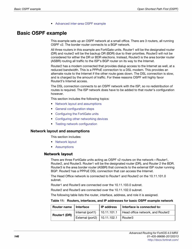
Basic OSPF example Open Shortest Path First (OSPF)
• Advanced inter-area OSPF example
Basic OSPF example
This example sets up an OSPF network at a small office. There are 3 routers, all running
OSPF v2. The border router connects to a BGP network.
All three routers in this example are FortiGate units. Router1 will be the designated router
(DR) and router2 will be the backup DR (BDR) due to their priorities. Router3 will not be
considered for either the DR or BDR elections. Instead, Router3 is the area border router
(ASBR) routing all traffic to the ISP’s BGP router on its way to the Internet.
Router2 has a modem connected that provides dialup access to the Internet as well, at a
reduced bandwidth. This is a PPPoE connection to a DSL modem. This provides an
alternate route to the Internet if the other route goes down. The DSL connection is slow,
and is charged by the amount of traffic. For these reasons OSPF will highly favor
Router3’s Internet access.
The DSL connection connects to an OSPF network with the ISP, so no redistribution of
routes is required. The ISP network does have to be added to that router’s configuration
however.
This section includes the following topics:
• Network layout and assumptions
• General configuration steps
• Configuring the FortiGate units
• Configuring other networking devices
• Testing network configuration
Network layout and assumptions
This section includes:
• Network layout
• Assumptions
Network layoutThere are three FortiGate units acting as OSPF v2 routers on the network—Router1,
Router2, and Router3. Router1 will be the designated router (DR), and Router 2 the BDR.
Router3 is the area border router (ASBR) that connects to the external ISP router running
BGP. Router2 has a PPPoE DSL connection that can access the Internet.
The Head Office network is connected to Router1 and Router2 on the 10.11.101.0
subnet.
Router1 and Router3 are connected over the 10.11.103.0 subnet.
Router2 and Router3 are connected over the 10.11.102.0 subnet.
The following table lists the router, interface, address, and role it is assigned.
Table 11: Routers, interfaces, and IP addresses for basic OSPF example network
Router name Interface IP address Interface is connected to:
Router1 (DR)Internal (port1) 10.11.101.1 Head office network, and Router2
External (port2) 10.11.102.1 Router3
Advanced Routing for FortiOS 4.0 MR3
146 01-435-99686-20120313
http://docs.fortinet.com/
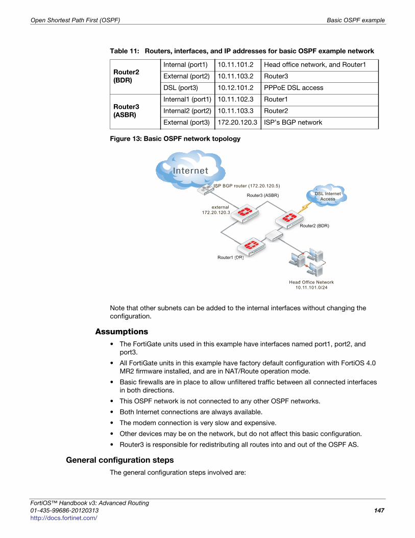
Open Shortest Path First (OSPF) Basic OSPF example
F
0
h
Figure 13: Basic OSPF network topology
Note that other subnets can be added to the internal interfaces without changing the
configuration.
Assumptions• The FortiGate units used in this example have interfaces named port1, port2, and
port3.
• All FortiGate units in this example have factory default configuration with FortiOS 4.0
MR2 firmware installed, and are in NAT/Route operation mode.
• Basic firewalls are in place to allow unfiltered traffic between all connected interfaces
in both directions.
• This OSPF network is not connected to any other OSPF networks.
• Both Internet connections are always available.
• The modem connection is very slow and expensive.
• Other devices may be on the network, but do not affect this basic configuration.
• Router3 is responsible for redistributing all routes into and out of the OSPF AS.
General configuration steps
The general configuration steps involved are:
Router2
(BDR)
Internal (port1) 10.11.101.2 Head office network, and Router1
External (port2) 10.11.103.2 Router3
DSL (port3) 10.12.101.2 PPPoE DSL access
Router3
(ASBR)
Internal1 (port1) 10.11.102.3 Router1
Internal2 (port2) 10.11.103.3 Router2
External (port3) 172.20.120.3 ISP’s BGP network
Table 11: Routers, interfaces, and IP addresses for basic OSPF example network
Router3 (ASBR)
Head Office Network10.11.101.0/24
Router1 (DR)
Router2 (BDR)
ISP BGP router (172.20.120.5)
external 172.20.120.3
l 33
DSL InternetAccess
RoRRou
(DR)R))R)
ortiOS™ Handbook v3: Advanced Routing
1-435-99686-20120313 147
ttp://docs.fortinet.com/
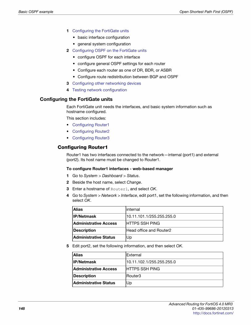
Basic OSPF example Open Shortest Path First (OSPF)
1 Configuring the FortiGate units
• basic interface configuration
• general system configuration
2 Configuring OSPF on the FortiGate units
• configure OSPF for each interface
• configure general OSPF settings for each router
• Configure each router as one of DR, BDR, or ASBR
• Configure route redistribution between BGP and OSPF
3 Configuring other networking devices
4 Testing network configuration
Configuring the FortiGate units
Each FortiGate unit needs the interfaces, and basic system information such as
hostname configured.
This section includes:
• Configuring Router1
• Configuring Router2
• Configuring Router3
Configuring Router1Router1 has two interfaces connected to the network—internal (port1) and external
(port2). Its host name must be changed to Router1.
To configure Router1 interfaces - web-based manager
1 Go to System > Dashboard > Status.
2 Beside the host name, select Change.
3 Enter a hostname of Router1, and select OK.
4 Go to System > Network > Interface, edit port1, set the following information, and then
select OK.
5 Edit port2, set the following information, and then select OK.
Alias internal
IP/Netmask 10.11.101.1/255.255.255.0
Administrative Access HTTPS SSH PING
Description Head office and Router2
Administrative Status Up
Alias External
IP/Netmask 10.11.102.1/255.255.255.0
Administrative Access HTTPS SSH PING
Description Router3
Administrative Status Up
Advanced Routing for FortiOS 4.0 MR3
148 01-435-99686-20120313
http://docs.fortinet.com/
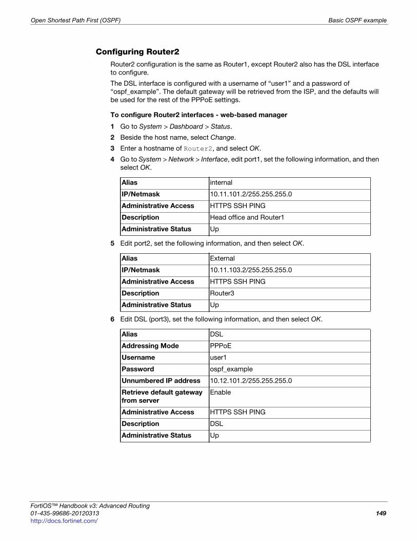
Open Shortest Path First (OSPF) Basic OSPF example
F
0
h
Configuring Router2Router2 configuration is the same as Router1, except Router2 also has the DSL interface
to configure.
The DSL interface is configured with a username of “user1” and a password of
“ospf_example”. The default gateway will be retrieved from the ISP, and the defaults will
be used for the rest of the PPPoE settings.
To configure Router2 interfaces - web-based manager
1 Go to System > Dashboard > Status.
2 Beside the host name, select Change.
3 Enter a hostname of Router2, and select OK.
4 Go to System > Network > Interface, edit port1, set the following information, and then
select OK.
5 Edit port2, set the following information, and then select OK.
6 Edit DSL (port3), set the following information, and then select OK.
Alias internal
IP/Netmask 10.11.101.2/255.255.255.0
Administrative Access HTTPS SSH PING
Description Head office and Router1
Administrative Status Up
Alias External
IP/Netmask 10.11.103.2/255.255.255.0
Administrative Access HTTPS SSH PING
Description Router3
Administrative Status Up
Alias DSL
Addressing Mode PPPoE
Username user1
Password ospf_example
Unnumbered IP address 10.12.101.2/255.255.255.0
Retrieve default gateway
from server
Enable
Administrative Access HTTPS SSH PING
Description DSL
Administrative Status Up
ortiOS™ Handbook v3: Advanced Routing
1-435-99686-20120313 149
ttp://docs.fortinet.com/
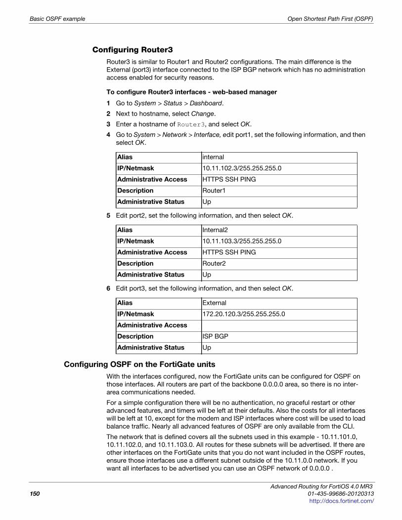
Basic OSPF example Open Shortest Path First (OSPF)
Configuring Router3Router3 is similar to Router1 and Router2 configurations. The main difference is the
External (port3) interface connected to the ISP BGP network which has no administration
access enabled for security reasons.
To configure Router3 interfaces - web-based manager
1 Go to System > Status > Dashboard.
2 Next to hostname, select Change.
3 Enter a hostname of Router3, and select OK.
4 Go to System > Network > Interface, edit port1, set the following information, and then
select OK.
5 Edit port2, set the following information, and then select OK.
6 Edit port3, set the following information, and then select OK.
Configuring OSPF on the FortiGate units
With the interfaces configured, now the FortiGate units can be configured for OSPF on
those interfaces. All routers are part of the backbone 0.0.0.0 area, so there is no inter-
area communications needed.
For a simple configuration there will be no authentication, no graceful restart or other
advanced features, and timers will be left at their defaults. Also the costs for all interfaces
will be left at 10, except for the modem and ISP interfaces where cost will be used to load
balance traffic. Nearly all advanced features of OSPF are only available from the CLI.
The network that is defined covers all the subnets used in this example - 10.11.101.0,
10.11.102.0, and 10.11.103.0. All routes for these subnets will be advertised. If there are
other interfaces on the FortiGate units that you do not want included in the OSPF routes,
ensure those interfaces use a different subnet outside of the 10.11.0.0 network. If you
want all interfaces to be advertised you can use an OSPF network of 0.0.0.0 .
Alias internal
IP/Netmask 10.11.102.3/255.255.255.0
Administrative Access HTTPS SSH PING
Description Router1
Administrative Status Up
Alias Internal2
IP/Netmask 10.11.103.3/255.255.255.0
Administrative Access HTTPS SSH PING
Description Router2
Administrative Status Up
Alias External
IP/Netmask 172.20.120.3/255.255.255.0
Administrative Access
Description ISP BGP
Administrative Status Up
Advanced Routing for FortiOS 4.0 MR3
150 01-435-99686-20120313
http://docs.fortinet.com/
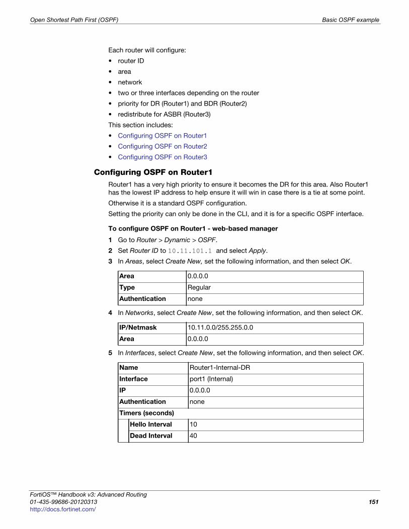
Open Shortest Path First (OSPF) Basic OSPF example
F
0
h
Each router will configure:
• router ID
• area
• network
• two or three interfaces depending on the router
• priority for DR (Router1) and BDR (Router2)
• redistribute for ASBR (Router3)
This section includes:
• Configuring OSPF on Router1
• Configuring OSPF on Router2
• Configuring OSPF on Router3
Configuring OSPF on Router1Router1 has a very high priority to ensure it becomes the DR for this area. Also Router1
has the lowest IP address to help ensure it will win in case there is a tie at some point.
Otherwise it is a standard OSPF configuration.
Setting the priority can only be done in the CLI, and it is for a specific OSPF interface.
To configure OSPF on Router1 - web-based manager
1 Go to Router > Dynamic > OSPF.
2 Set Router ID to 10.11.101.1 and select Apply.
3 In Areas, select Create New, set the following information, and then select OK.
4 In Networks, select Create New, set the following information, and then select OK.
5 In Interfaces, select Create New, set the following information, and then select OK.
Area 0.0.0.0
Type Regular
Authentication none
IP/Netmask 10.11.0.0/255.255.0.0
Area 0.0.0.0
Name Router1-Internal-DR
Interface port1 (Internal)
IP 0.0.0.0
Authentication none
Timers (seconds)
Hello Interval 10
Dead Interval 40
ortiOS™ Handbook v3: Advanced Routing
1-435-99686-20120313 151
ttp://docs.fortinet.com/
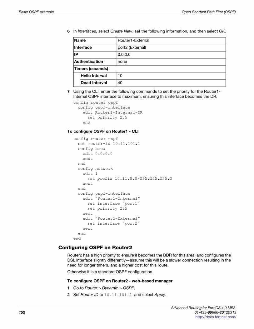
Basic OSPF example Open Shortest Path First (OSPF)
6 In Interfaces, select Create New, set the following information, and then select OK.
7 Using the CLI, enter the following commands to set the priority for the Router1-
Internal OSPF interface to maximum, ensuring this interface becomes the DR.
config router ospf config ospf-interfaceedit Router1-Internal-DRset priority 255
end
To configure OSPF on Router1 - CLI
config router ospfset router-id 10.11.101.1config areaedit 0.0.0.0next
endconfig networkedit 1set prefix 10.11.0.0/255.255.255.0
nextendconfig ospf-interfaceedit "Router1-Internal"set interface "port1"set priority 255
nextedit "Router1-External"set interface "port2"
nextend
end
Configuring OSPF on Router2Router2 has a high priority to ensure it becomes the BDR for this area, and configures the
DSL interface slightly differently—assume this will be a slower connection resulting in the
need for longer timers, and a higher cost for this route.
Otherwise it is a standard OSPF configuration.
To configure OSPF on Router2 - web-based manager
1 Go to Router > Dynamic > OSPF.
2 Set Router ID to 10.11.101.2 and select Apply.
Name Router1-External
Interface port2 (External)
IP 0.0.0.0
Authentication none
Timers (seconds)
Hello Interval 10
Dead Interval 40
Advanced Routing for FortiOS 4.0 MR3
152 01-435-99686-20120313
http://docs.fortinet.com/
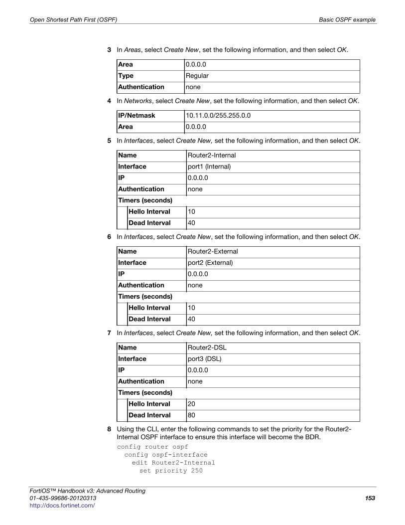
Open Shortest Path First (OSPF) Basic OSPF example
F
0
h
3 In Areas, select Create New, set the following information, and then select OK.
4 In Networks, select Create New, set the following information, and then select OK.
5 In Interfaces, select Create New, set the following information, and then select OK.
6 In Interfaces, select Create New, set the following information, and then select OK.
7 In Interfaces, select Create New, set the following information, and then select OK.
8 Using the CLI, enter the following commands to set the priority for the Router2-
Internal OSPF interface to ensure this interface will become the BDR.
config router ospf config ospf-interfaceedit Router2-Internalset priority 250
Area 0.0.0.0
Type Regular
Authentication none
IP/Netmask 10.11.0.0/255.255.0.0
Area 0.0.0.0
Name Router2-Internal
Interface port1 (Internal)
IP 0.0.0.0
Authentication none
Timers (seconds)
Hello Interval 10
Dead Interval 40
Name Router2-External
Interface port2 (External)
IP 0.0.0.0
Authentication none
Timers (seconds)
Hello Interval 10
Dead Interval 40
Name Router2-DSL
Interface port3 (DSL)
IP 0.0.0.0
Authentication none
Timers (seconds)
Hello Interval 20
Dead Interval 80
ortiOS™ Handbook v3: Advanced Routing
1-435-99686-20120313 153
ttp://docs.fortinet.com/
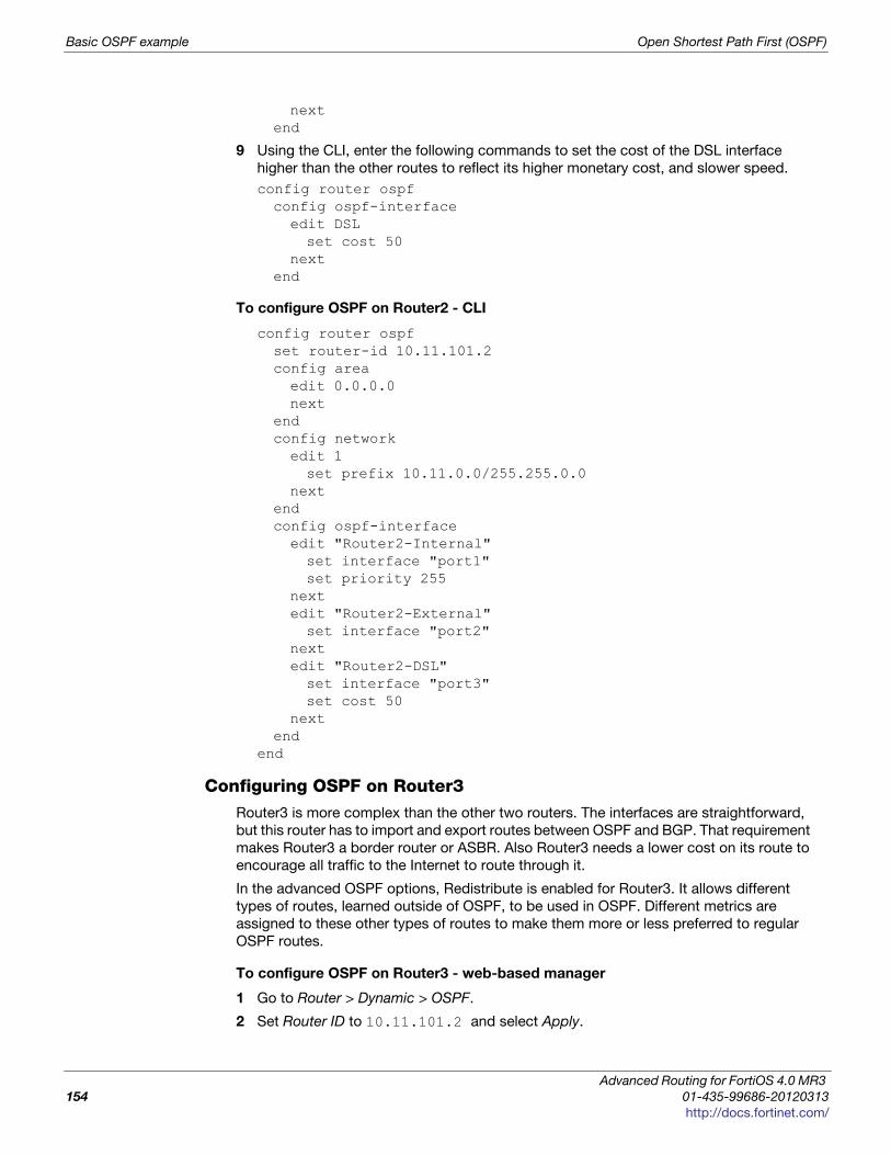
Basic OSPF example Open Shortest Path First (OSPF)
nextend
9 Using the CLI, enter the following commands to set the cost of the DSL interface
higher than the other routes to reflect its higher monetary cost, and slower speed.
config router ospf config ospf-interfaceedit DSLset cost 50
nextend
To configure OSPF on Router2 - CLI
config router ospfset router-id 10.11.101.2config areaedit 0.0.0.0next
endconfig networkedit 1set prefix 10.11.0.0/255.255.0.0
nextendconfig ospf-interfaceedit "Router2-Internal"set interface "port1"set priority 255
nextedit "Router2-External"set interface "port2"
nextedit "Router2-DSL"set interface "port3"set cost 50
nextend
end
Configuring OSPF on Router3Router3 is more complex than the other two routers. The interfaces are straightforward,
but this router has to import and export routes between OSPF and BGP. That requirement
makes Router3 a border router or ASBR. Also Router3 needs a lower cost on its route to
encourage all traffic to the Internet to route through it.
In the advanced OSPF options, Redistribute is enabled for Router3. It allows different
types of routes, learned outside of OSPF, to be used in OSPF. Different metrics are
assigned to these other types of routes to make them more or less preferred to regular
OSPF routes.
To configure OSPF on Router3 - web-based manager
1 Go to Router > Dynamic > OSPF.
2 Set Router ID to 10.11.101.2 and select Apply.
Advanced Routing for FortiOS 4.0 MR3
154 01-435-99686-20120313
http://docs.fortinet.com/
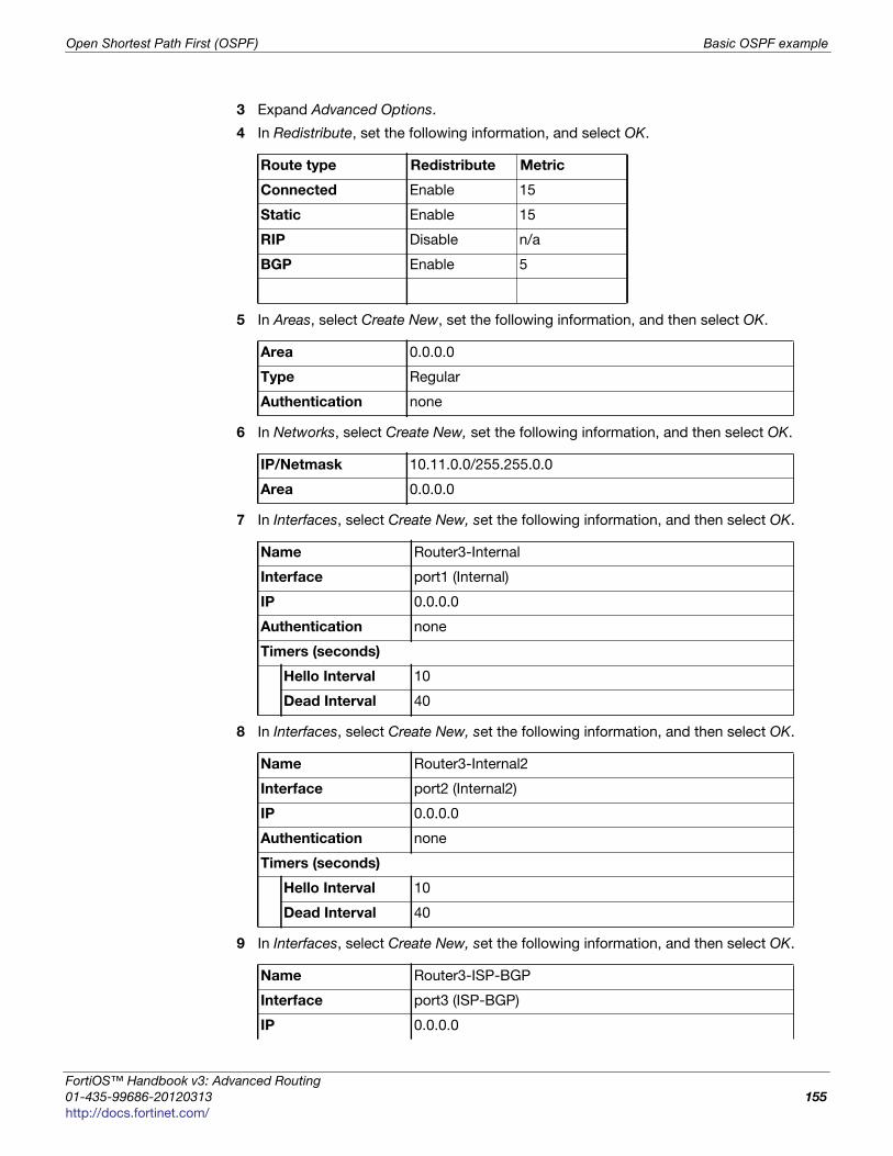
Open Shortest Path First (OSPF) Basic OSPF example
F
0
h
3 Expand Advanced Options.
4 In Redistribute, set the following information, and select OK.
5 In Areas, select Create New, set the following information, and then select OK.
6 In Networks, select Create New, set the following information, and then select OK.
7 In Interfaces, select Create New, set the following information, and then select OK.
8 In Interfaces, select Create New, set the following information, and then select OK.
9 In Interfaces, select Create New, set the following information, and then select OK.
Route type Redistribute Metric
Connected Enable 15
Static Enable 15
RIP Disable n/a
BGP Enable 5
Area 0.0.0.0
Type Regular
Authentication none
IP/Netmask 10.11.0.0/255.255.0.0
Area 0.0.0.0
Name Router3-Internal
Interface port1 (Internal)
IP 0.0.0.0
Authentication none
Timers (seconds)
Hello Interval 10
Dead Interval 40
Name Router3-Internal2
Interface port2 (Internal2)
IP 0.0.0.0
Authentication none
Timers (seconds)
Hello Interval 10
Dead Interval 40
Name Router3-ISP-BGP
Interface port3 (ISP-BGP)
IP 0.0.0.0
ortiOS™ Handbook v3: Advanced Routing
1-435-99686-20120313 155
ttp://docs.fortinet.com/
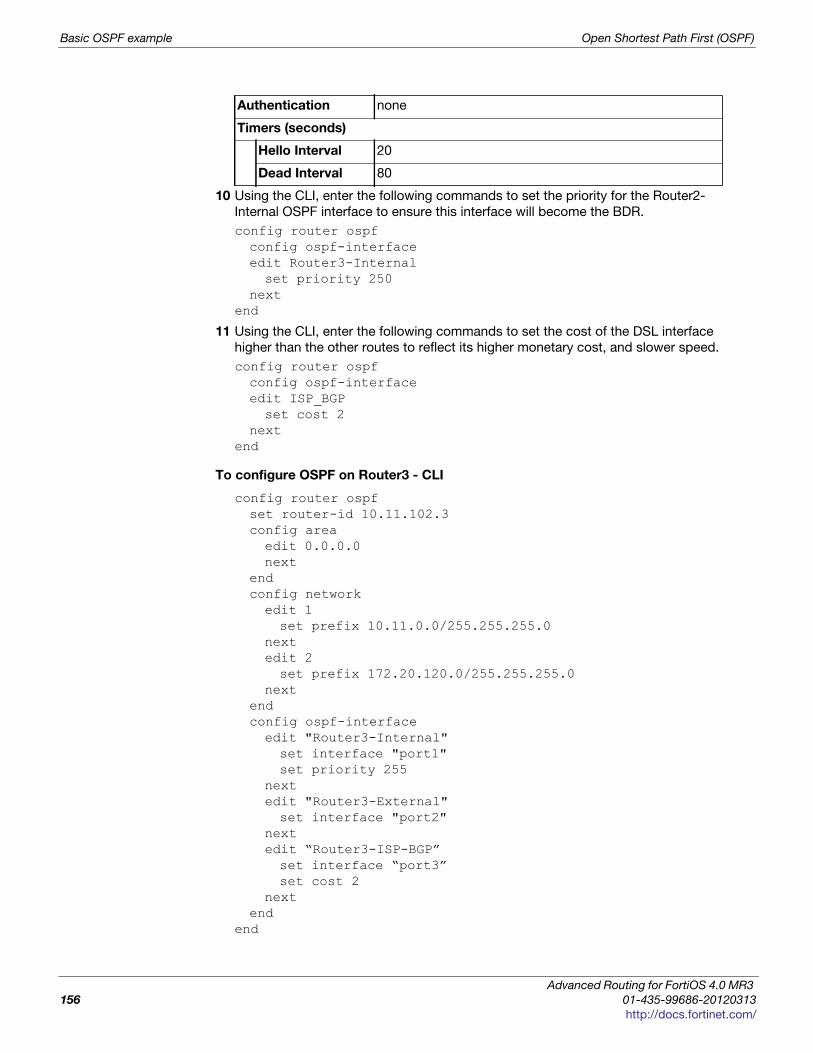
Basic OSPF example Open Shortest Path First (OSPF)
10 Using the CLI, enter the following commands to set the priority for the Router2-
Internal OSPF interface to ensure this interface will become the BDR.
config router ospf config ospf-interfaceedit Router3-Internalset priority 250
nextend
11 Using the CLI, enter the following commands to set the cost of the DSL interface
higher than the other routes to reflect its higher monetary cost, and slower speed.
config router ospf config ospf-interfaceedit ISP_BGPset cost 2
nextend
To configure OSPF on Router3 - CLI
config router ospfset router-id 10.11.102.3config areaedit 0.0.0.0next
endconfig networkedit 1set prefix 10.11.0.0/255.255.255.0
nextedit 2set prefix 172.20.120.0/255.255.255.0
nextendconfig ospf-interfaceedit "Router3-Internal"set interface "port1"set priority 255
nextedit "Router3-External"set interface "port2"
nextedit “Router3-ISP-BGP”set interface “port3”set cost 2
nextend
end
Authentication none
Timers (seconds)
Hello Interval 20
Dead Interval 80
Advanced Routing for FortiOS 4.0 MR3
156 01-435-99686-20120313
http://docs.fortinet.com/
Open Shortest Path First (OSPF) Advanced inter-area OSPF example
F
0
h
Configuring other networking devices
The other networking devices required in this configuration are on the two ISP networks -
the BGP network for the main Internet connection, and the DSL backup connection.
In both cases, the ISPs need to be notified of the OSPF network settings including router
IP addresses, timer settings, and so on. The ISP will use this information to configure its
routers that connect to this OSPF network.
Testing network configuration
Testing the network configuration involves two parts —testing the network connectivity,
and testing the OSPF routing.
To test the network connectivity use ping, traceroute, and other network tools.
To test the OSPF routing in this example, refer to the troubleshooting outlined in
“Troubleshooting OSPF” on page 143.
Advanced inter-area OSPF example
This example sets up an OSPF network at a large office. There are 3 areas, each with 2
routers. Typically OSPF areas would not be this small, and if they were the areas would
be combined into one bigger area. However, the stub area services the accounting
department which is very sensitive about their network and do not want any of their
network information broadcast through the rest of the company. The backbone area
contains the bulk of the company network devices. The regular area was established by
IT for various reasons such as hosting the company servers on a separate area with extra
security
One area is a small stub area that has no independent Internet connection, and only one
connection to the backbone area. That connection between the stub area and the
backbone area is only through a default route - no routes outside the stub area are
advertised into that area.
Another area is the backbone, which is connected to the other two areas. The third area
has the Internet connection, and all traffic to and from the Internet must use that area’s
connection. If that traffic comes from the stub area, then that traffic is treating the
backbone like a transit area - an area it only uses to get to another area.
In the stub area, a subnet of computers is running the RIP routing protocol and those
routes must be redistributed into the OSPF areas.
This section includes the following topics:
• Network layout and assumptions
• General configuration steps
• Configuring the FortiGate units
• Configuring other networking devices
• Testing network configuration
Network layout and assumptions
This section includes:
• Network layout
• Assumptions
ortiOS™ Handbook v3: Advanced Routing
1-435-99686-20120313 157
ttp://docs.fortinet.com/
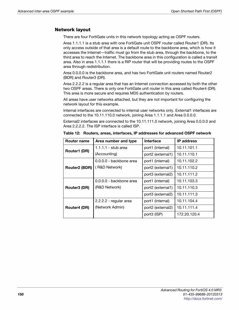
Advanced inter-area OSPF example Open Shortest Path First (OSPF)
Network layoutThere are four FortiGate units in this network topology acting as OSPF routers.
Area 1.1.1.1 is a stub area with one FortiGate unit OSPF router called Router1 (DR). Its
only access outside of that area is a default route to the backbone area, which is how it
accesses the Internet—traffic must go from the stub area, through the backbone, to the
third area to reach the Internet. The backbone area in this configuration is called a transit
area. Also in area 1.1.1.1 there is a RIP router that will be providing routes to the OSPF
area through redistribution.
Area 0.0.0.0 is the backbone area, and has two FortiGate unit routers named Router2
(BDR) and Router3 (DR).
Area 2.2.2.2 is a regular area that has an Internet connection accessed by both the other
two OSPF areas. There is only one FortiGate unit router in this area called Router4 (DR).
This area is more secure and requires MD5 authentication by routers.
All areas have user networks attached, but they are not important for configuring the
network layout for this example.
Internal interfaces are connected to internal user networks only. External1 interfaces are
connected to the 10.11.110.0 network, joining Area 1.1.1.1 and Area 0.0.0.0.
External2 interfaces are connected to the 10.11.111.0 network, joining Area 0.0.0.0 and
Area 2.2.2.2. The ISP interface is called ISP.
Table 12: Routers, areas, interfaces, IP addresses for advanced OSPF network
Router name Area number and type Interface IP address
Router1 (DR)1.1.1.1 - stub area
(Accounting)
port1 (internal) 10.11.101.1
port2 (external1) 10.11.110.1
Router2 (BDR)
0.0.0.0 - backbone area
( R&D Network)
port1 (internal) 10.11.102.2
port2 (external1) 10.11.110.2
port3 (external2) 10.11.111.2
Router3 (DR)
0.0.0.0 - backbone area
(R&D Network)
port1 (internal) 10.11.103.3
port2 (external1) 10.11.110.3
port3 (external2) 10.11.111.3
Router4 (DR)
2.2.2.2 - regular area
(Network Admin)
port1 (internal) 10.11.104.4
port2 (external2) 10.11.111.4
port3 (ISP) 172.20.120.4
Advanced Routing for FortiOS 4.0 MR3
158 01-435-99686-20120313
http://docs.fortinet.com/
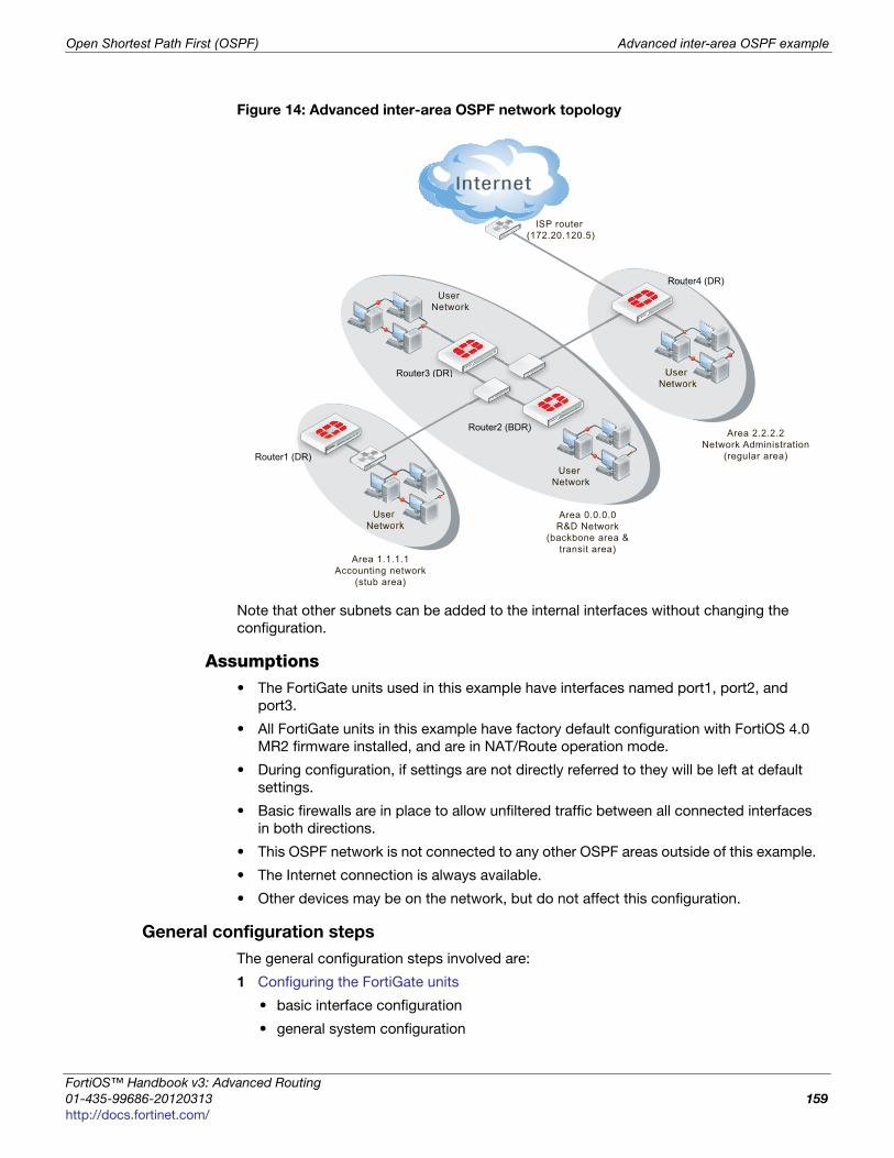
Open Shortest Path First (OSPF) Advanced inter-area OSPF example
F
0
h
Figure 14: Advanced inter-area OSPF network topology
Note that other subnets can be added to the internal interfaces without changing the
configuration.
Assumptions• The FortiGate units used in this example have interfaces named port1, port2, and
port3.
• All FortiGate units in this example have factory default configuration with FortiOS 4.0
MR2 firmware installed, and are in NAT/Route operation mode.
• During configuration, if settings are not directly referred to they will be left at default
settings.
• Basic firewalls are in place to allow unfiltered traffic between all connected interfaces
in both directions.
• This OSPF network is not connected to any other OSPF areas outside of this example.
• The Internet connection is always available.
• Other devices may be on the network, but do not affect this configuration.
General configuration steps
The general configuration steps involved are:
1 Configuring the FortiGate units
• basic interface configuration
• general system configuration
Router3 (DR)
ISP router (172.20.120.5)
Router2 (BDR)
Area 0.0.0.0R&D Network
(backbone area &transit area)
User Network
User Network
Router1 (DR)
User Network
Area 1.1.1.1Accounting network
(stub area)
DDR)R)
Router4 (DR)
Area 2.2.2.2Network Administration
(regular area)
User Network
(DDDR)R)R)))R)R)
DRR)))
ortiOS™ Handbook v3: Advanced Routing
1-435-99686-20120313 159
ttp://docs.fortinet.com/
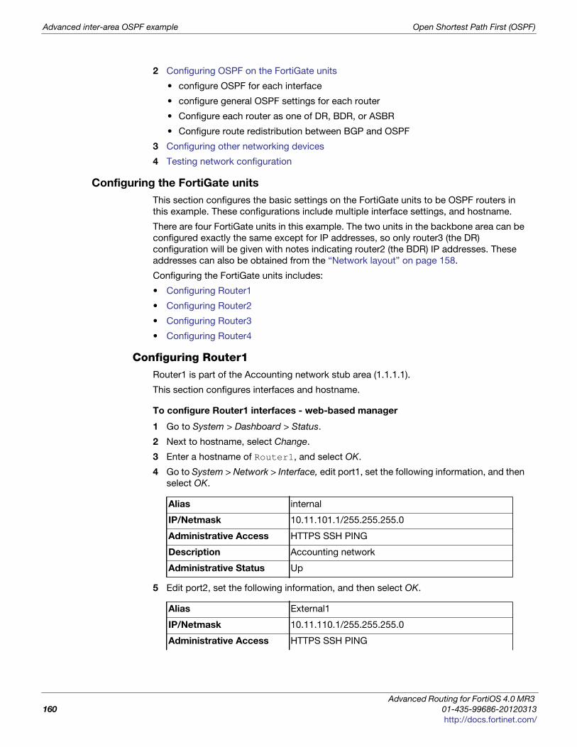
Advanced inter-area OSPF example Open Shortest Path First (OSPF)
2 Configuring OSPF on the FortiGate units
• configure OSPF for each interface
• configure general OSPF settings for each router
• Configure each router as one of DR, BDR, or ASBR
• Configure route redistribution between BGP and OSPF
3 Configuring other networking devices
4 Testing network configuration
Configuring the FortiGate units
This section configures the basic settings on the FortiGate units to be OSPF routers in
this example. These configurations include multiple interface settings, and hostname.
There are four FortiGate units in this example. The two units in the backbone area can be
configured exactly the same except for IP addresses, so only router3 (the DR)
configuration will be given with notes indicating router2 (the BDR) IP addresses. These
addresses can also be obtained from the “Network layout” on page 158.
Configuring the FortiGate units includes:
• Configuring Router1
• Configuring Router2
• Configuring Router3
• Configuring Router4
Configuring Router1Router1 is part of the Accounting network stub area (1.1.1.1).
This section configures interfaces and hostname.
To configure Router1 interfaces - web-based manager
1 Go to System > Dashboard > Status.
2 Next to hostname, select Change.
3 Enter a hostname of Router1, and select OK.
4 Go to System > Network > Interface, edit port1, set the following information, and then
select OK.
5 Edit port2, set the following information, and then select OK.
Alias internal
IP/Netmask 10.11.101.1/255.255.255.0
Administrative Access HTTPS SSH PING
Description Accounting network
Administrative Status Up
Alias External1
IP/Netmask 10.11.110.1/255.255.255.0
Administrative Access HTTPS SSH PING
Advanced Routing for FortiOS 4.0 MR3
160 01-435-99686-20120313
http://docs.fortinet.com/
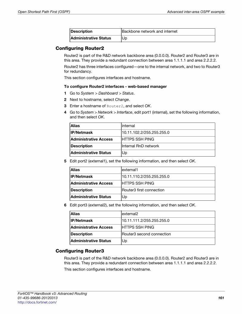
Open Shortest Path First (OSPF) Advanced inter-area OSPF example
F
0
h
Configuring Router2Router2 is part of the R&D network backbone area (0.0.0.0). Router2 and Router3 are in
this area. They provide a redundant connection between area 1.1.1.1 and area 2.2.2.2.
Router2 has three interfaces configured—one to the internal network, and two to Router3
for redundancy.
This section configures interfaces and hostname.
To configure Router2 interfaces - web-based manager
1 Go to System > Dashboard > Status.
2 Next to hostname, select Change.
3 Enter a hostname of Router2, and select OK.
4 Go to System > Network > Interface, edit port1 (internal), set the following information,
and then select OK.
5 Edit port2 (external1), set the following information, and then select OK.
6 Edit port3 (external2), set the following information, and then select OK.
Configuring Router3Router3 is part of the R&D network backbone area (0.0.0.0). Router2 and Router3 are in
this area. They provide a redundant connection between area 1.1.1.1 and area 2.2.2.2.
This section configures interfaces and hostname.
Description Backbone network and internet
Administrative Status Up
Alias internal
IP/Netmask 10.11.102.2/255.255.255.0
Administrative Access HTTPS SSH PING
Description Internal RnD network
Administrative Status Up
Alias external1
IP/Netmask 10.11.110.2/255.255.255.0
Administrative Access HTTPS SSH PING
Description Router3 first connection
Administrative Status Up
Alias external2
IP/Netmask 10.11.111.2/255.255.255.0
Administrative Access HTTPS SSH PING
Description Router3 second connection
Administrative Status Up
ortiOS™ Handbook v3: Advanced Routing
1-435-99686-20120313 161
ttp://docs.fortinet.com/
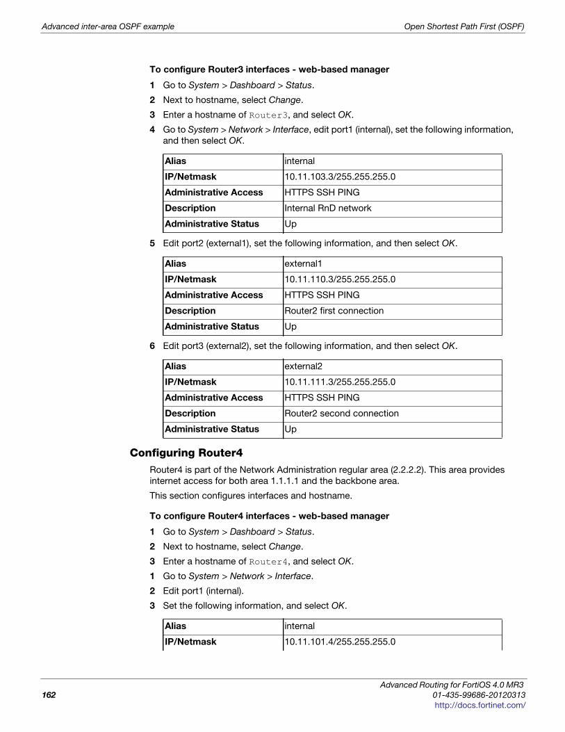
Advanced inter-area OSPF example Open Shortest Path First (OSPF)
To configure Router3 interfaces - web-based manager
1 Go to System > Dashboard > Status.
2 Next to hostname, select Change.
3 Enter a hostname of Router3, and select OK.
4 Go to System > Network > Interface, edit port1 (internal), set the following information,
and then select OK.
5 Edit port2 (external1), set the following information, and then select OK.
6 Edit port3 (external2), set the following information, and then select OK.
Configuring Router4Router4 is part of the Network Administration regular area (2.2.2.2). This area provides
internet access for both area 1.1.1.1 and the backbone area.
This section configures interfaces and hostname.
To configure Router4 interfaces - web-based manager
1 Go to System > Dashboard > Status.
2 Next to hostname, select Change.
3 Enter a hostname of Router4, and select OK.
1 Go to System > Network > Interface.
2 Edit port1 (internal).
3 Set the following information, and select OK.
Alias internal
IP/Netmask 10.11.103.3/255.255.255.0
Administrative Access HTTPS SSH PING
Description Internal RnD network
Administrative Status Up
Alias external1
IP/Netmask 10.11.110.3/255.255.255.0
Administrative Access HTTPS SSH PING
Description Router2 first connection
Administrative Status Up
Alias external2
IP/Netmask 10.11.111.3/255.255.255.0
Administrative Access HTTPS SSH PING
Description Router2 second connection
Administrative Status Up
Alias internal
IP/Netmask 10.11.101.4/255.255.255.0
Advanced Routing for FortiOS 4.0 MR3
162 01-435-99686-20120313
http://docs.fortinet.com/
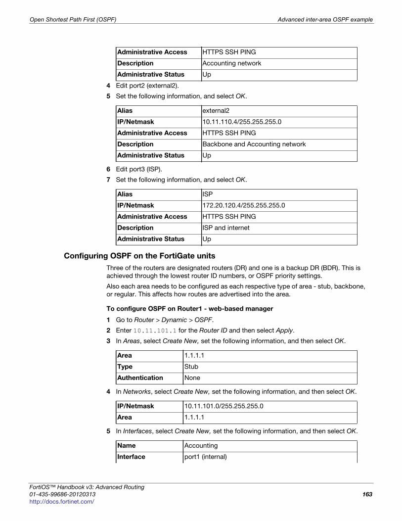
Open Shortest Path First (OSPF) Advanced inter-area OSPF example
F
0
h
4 Edit port2 (external2).
5 Set the following information, and select OK.
6 Edit port3 (ISP).
7 Set the following information, and select OK.
Configuring OSPF on the FortiGate units
Three of the routers are designated routers (DR) and one is a backup DR (BDR). This is
achieved through the lowest router ID numbers, or OSPF priority settings.
Also each area needs to be configured as each respective type of area - stub, backbone,
or regular. This affects how routes are advertised into the area.
To configure OSPF on Router1 - web-based manager
1 Go to Router > Dynamic > OSPF.
2 Enter 10.11.101.1 for the Router ID and then select Apply.
3 In Areas, select Create New, set the following information, and then select OK.
4 In Networks, select Create New, set the following information, and then select OK.
5 In Interfaces, select Create New, set the following information, and then select OK.
Administrative Access HTTPS SSH PING
Description Accounting network
Administrative Status Up
Alias external2
IP/Netmask 10.11.110.4/255.255.255.0
Administrative Access HTTPS SSH PING
Description Backbone and Accounting network
Administrative Status Up
Alias ISP
IP/Netmask 172.20.120.4/255.255.255.0
Administrative Access HTTPS SSH PING
Description ISP and internet
Administrative Status Up
Area 1.1.1.1
Type Stub
Authentication None
IP/Netmask 10.11.101.0/255.255.255.0
Area 1.1.1.1
Name Accounting
Interface port1 (internal)
ortiOS™ Handbook v3: Advanced Routing
1-435-99686-20120313 163
ttp://docs.fortinet.com/
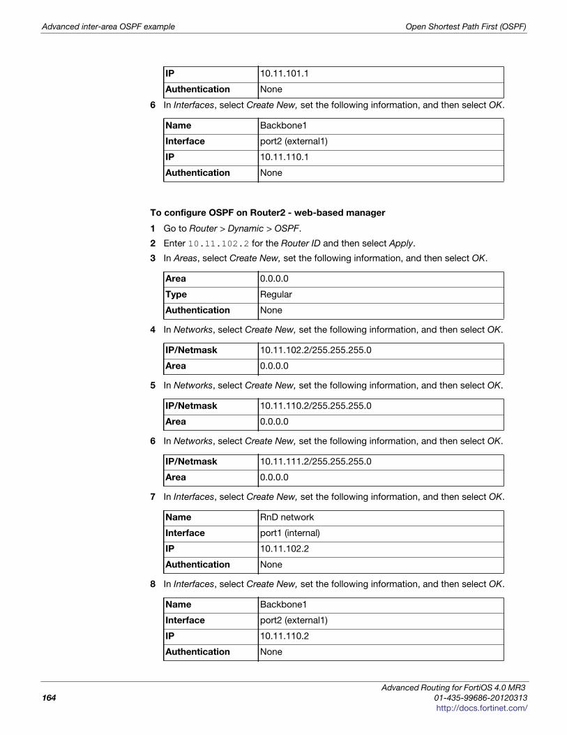
Advanced inter-area OSPF example Open Shortest Path First (OSPF)
6 In Interfaces, select Create New, set the following information, and then select OK.
To configure OSPF on Router2 - web-based manager
1 Go to Router > Dynamic > OSPF.
2 Enter 10.11.102.2 for the Router ID and then select Apply.
3 In Areas, select Create New, set the following information, and then select OK.
4 In Networks, select Create New, set the following information, and then select OK.
5 In Networks, select Create New, set the following information, and then select OK.
6 In Networks, select Create New, set the following information, and then select OK.
7 In Interfaces, select Create New, set the following information, and then select OK.
8 In Interfaces, select Create New, set the following information, and then select OK.
IP 10.11.101.1
Authentication None
Name Backbone1
Interface port2 (external1)
IP 10.11.110.1
Authentication None
Area 0.0.0.0
Type Regular
Authentication None
IP/Netmask 10.11.102.2/255.255.255.0
Area 0.0.0.0
IP/Netmask 10.11.110.2/255.255.255.0
Area 0.0.0.0
IP/Netmask 10.11.111.2/255.255.255.0
Area 0.0.0.0
Name RnD network
Interface port1 (internal)
IP 10.11.102.2
Authentication None
Name Backbone1
Interface port2 (external1)
IP 10.11.110.2
Authentication None
Advanced Routing for FortiOS 4.0 MR3
164 01-435-99686-20120313
http://docs.fortinet.com/
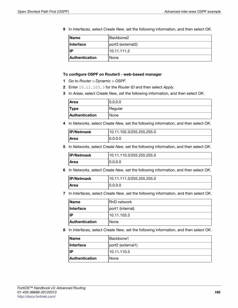
Open Shortest Path First (OSPF) Advanced inter-area OSPF example
F
0
h
9 In Interfaces, select Create New, set the following information, and then select OK.
To configure OSPF on Router3 - web-based manager
1 Go to Router > Dynamic > OSPF.
2 Enter 10.11.103.3 for the Router ID and then select Apply.
3 In Areas, select Create New, set the following information, and then select OK.
4 In Networks, select Create New, set the following information, and then select OK.
5 In Networks, select Create New, set the following information, and then select OK.
6 In Networks, select Create New, set the following information, and then select OK.
7 In Interfaces, select Create New, set the following information, and then select OK.
8 In Interfaces, select Create New, set the following information, and then select OK.
Name Backbone2
Interface port3 (external2)
IP 10.11.111.2
Authentication None
Area 0.0.0.0
Type Regular
Authentication None
IP/Netmask 10.11.102.3/255.255.255.0
Area 0.0.0.0
IP/Netmask 10.11.110.3/255.255.255.0
Area 0.0.0.0
IP/Netmask 10.11.111.3/255.255.255.0
Area 0.0.0.0
Name RnD network
Interface port1 (internal)
IP 10.11.103.3
Authentication None
Name Backbone1
Interface port2 (external1)
IP 10.11.110.3
Authentication None
ortiOS™ Handbook v3: Advanced Routing
1-435-99686-20120313 165
ttp://docs.fortinet.com/
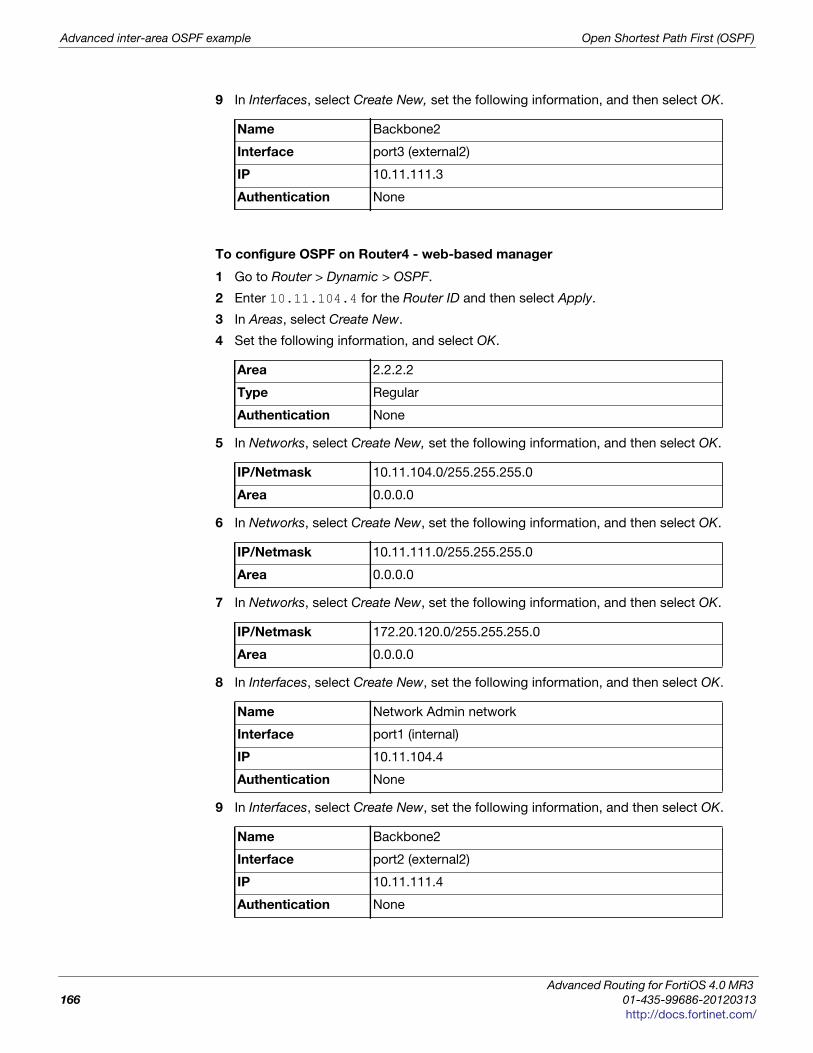
Advanced inter-area OSPF example Open Shortest Path First (OSPF)
9 In Interfaces, select Create New, set the following information, and then select OK.
To configure OSPF on Router4 - web-based manager
1 Go to Router > Dynamic > OSPF.
2 Enter 10.11.104.4 for the Router ID and then select Apply.
3 In Areas, select Create New.
4 Set the following information, and select OK.
5 In Networks, select Create New, set the following information, and then select OK.
6 In Networks, select Create New, set the following information, and then select OK.
7 In Networks, select Create New, set the following information, and then select OK.
8 In Interfaces, select Create New, set the following information, and then select OK.
9 In Interfaces, select Create New, set the following information, and then select OK.
Name Backbone2
Interface port3 (external2)
IP 10.11.111.3
Authentication None
Area 2.2.2.2
Type Regular
Authentication None
IP/Netmask 10.11.104.0/255.255.255.0
Area 0.0.0.0
IP/Netmask 10.11.111.0/255.255.255.0
Area 0.0.0.0
IP/Netmask 172.20.120.0/255.255.255.0
Area 0.0.0.0
Name Network Admin network
Interface port1 (internal)
IP 10.11.104.4
Authentication None
Name Backbone2
Interface port2 (external2)
IP 10.11.111.4
Authentication None
Advanced Routing for FortiOS 4.0 MR3
166 01-435-99686-20120313
http://docs.fortinet.com/
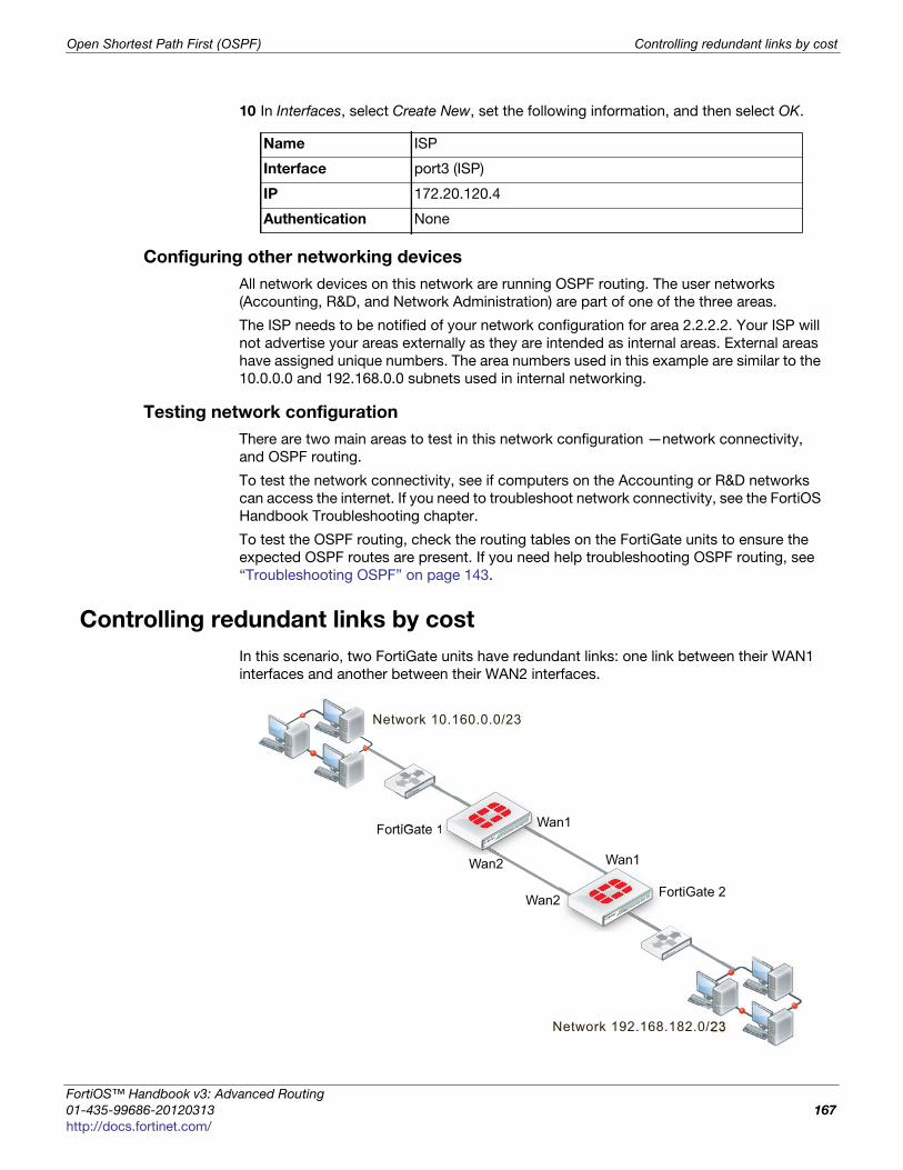
Open Shortest Path First (OSPF) Controlling redundant links by cost
F
0
h
10 In Interfaces, select Create New, set the following information, and then select OK.
Configuring other networking devices
All network devices on this network are running OSPF routing. The user networks
(Accounting, R&D, and Network Administration) are part of one of the three areas.
The ISP needs to be notified of your network configuration for area 2.2.2.2. Your ISP will
not advertise your areas externally as they are intended as internal areas. External areas
have assigned unique numbers. The area numbers used in this example are similar to the
10.0.0.0 and 192.168.0.0 subnets used in internal networking.
Testing network configuration
There are two main areas to test in this network configuration —network connectivity,
and OSPF routing.
To test the network connectivity, see if computers on the Accounting or R&D networks
can access the internet. If you need to troubleshoot network connectivity, see the FortiOS
Handbook Troubleshooting chapter.
To test the OSPF routing, check the routing tables on the FortiGate units to ensure the
expected OSPF routes are present. If you need help troubleshooting OSPF routing, see
“Troubleshooting OSPF” on page 143.
Controlling redundant links by cost
In this scenario, two FortiGate units have redundant links: one link between their WAN1
interfaces and another between their WAN2 interfaces.
Name ISP
Interface port3 (ISP)
IP 172.20.120.4
Authentication None
FortiGate 1
FortiGate 2
Network 10.160.0.0/23
Wan1
111
FFF
Wan1
Wan2
Wan2
Network 192.168.182.0/23
ortiOS™ Handbook v3: Advanced Routing
1-435-99686-20120313 167
ttp://docs.fortinet.com/
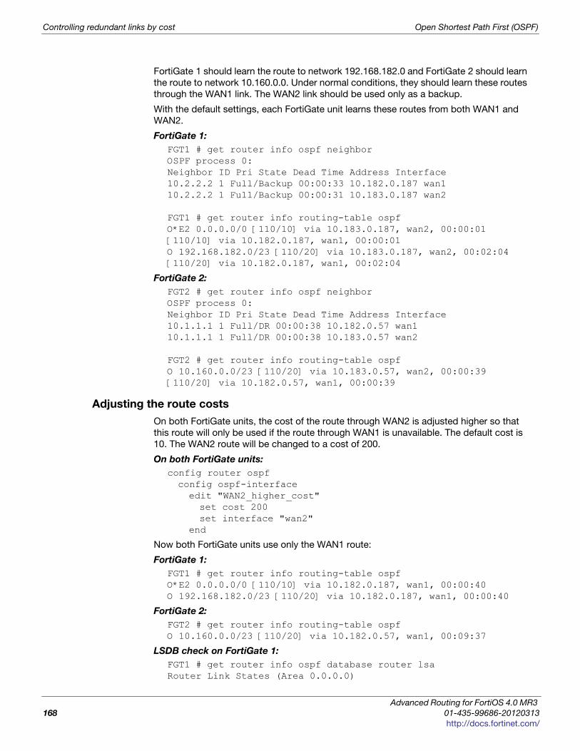
Controlling redundant links by cost Open Shortest Path First (OSPF)
FortiGate 1 should learn the route to network 192.168.182.0 and FortiGate 2 should learn
the route to network 10.160.0.0. Under normal conditions, they should learn these routes
through the WAN1 link. The WAN2 link should be used only as a backup.
With the default settings, each FortiGate unit learns these routes from both WAN1 and
WAN2.
FortiGate 1:
FGT1 # get router info ospf neighborOSPF process 0:Neighbor ID Pri State Dead Time Address Interface10.2.2.2 1 Full/Backup 00:00:33 10.182.0.187 wan110.2.2.2 1 Full/Backup 00:00:31 10.183.0.187 wan2
FGT1 # get router info routing-table ospfO*E2 0.0.0.0/0 [110/10] via 10.183.0.187, wan2, 00:00:01[110/10] via 10.182.0.187, wan1, 00:00:01O 192.168.182.0/23 [110/20] via 10.183.0.187, wan2, 00:02:04[110/20] via 10.182.0.187, wan1, 00:02:04
FortiGate 2:
FGT2 # get router info ospf neighborOSPF process 0:Neighbor ID Pri State Dead Time Address Interface10.1.1.1 1 Full/DR 00:00:38 10.182.0.57 wan110.1.1.1 1 Full/DR 00:00:38 10.183.0.57 wan2
FGT2 # get router info routing-table ospfO 10.160.0.0/23 [110/20] via 10.183.0.57, wan2, 00:00:39[110/20] via 10.182.0.57, wan1, 00:00:39
Adjusting the route costs
On both FortiGate units, the cost of the route through WAN2 is adjusted higher so that
this route will only be used if the route through WAN1 is unavailable. The default cost is
10. The WAN2 route will be changed to a cost of 200.
On both FortiGate units:
config router ospfconfig ospf-interfaceedit "WAN2_higher_cost"set cost 200set interface "wan2"
end
Now both FortiGate units use only the WAN1 route:
FortiGate 1:
FGT1 # get router info routing-table ospfO*E2 0.0.0.0/0 [110/10] via 10.182.0.187, wan1, 00:00:40O 192.168.182.0/23 [110/20] via 10.182.0.187, wan1, 00:00:40
FortiGate 2:
FGT2 # get router info routing-table ospfO 10.160.0.0/23 [110/20] via 10.182.0.57, wan1, 00:09:37
LSDB check on FortiGate 1:
FGT1 # get router info ospf database router lsaRouter Link States (Area 0.0.0.0)
Advanced Routing for FortiOS 4.0 MR3
168 01-435-99686-20120313
http://docs.fortinet.com/
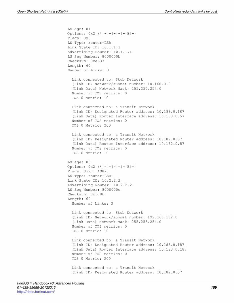
Open Shortest Path First (OSPF) Controlling redundant links by cost
F
0
h
LS age: 81Options: 0x2 (*|-|-|-|-|-|E|-)Flags: 0x0LS Type: router-LSALink State ID: 10.1.1.1Advertising Router: 10.1.1.1LS Seq Number: 8000000bChecksum: 0xe637Length: 60Number of Links: 3
Link connected to: Stub Network(Link ID) Network/subnet number: 10.160.0.0(Link Data) Network Mask: 255.255.254.0Number of TOS metrics: 0TOS 0 Metric: 10
Link connected to: a Transit Network(Link ID) Designated Router address: 10.183.0.187(Link Data) Router Interface address: 10.183.0.57Number of TOS metrics: 0TOS 0 Metric: 200
Link connected to: a Transit Network(Link ID) Designated Router address: 10.182.0.57(Link Data) Router Interface address: 10.182.0.57Number of TOS metrics: 0TOS 0 Metric: 10
LS age: 83Options: 0x2 (*|-|-|-|-|-|E|-)Flags: 0x2 : ASBRLS Type: router-LSALink State ID: 10.2.2.2Advertising Router: 10.2.2.2LS Seq Number: 8000000eChecksum: 0xfc9bLength: 60Number of Links: 3
Link connected to: Stub Network(Link ID) Network/subnet number: 192.168.182.0(Link Data) Network Mask: 255.255.254.0Number of TOS metrics: 0TOS 0 Metric: 10
Link connected to: a Transit Network(Link ID) Designated Router address: 10.183.0.187(Link Data) Router Interface address: 10.183.0.187Number of TOS metrics: 0TOS 0 Metric: 200
Link connected to: a Transit Network(Link ID) Designated Router address: 10.182.0.57
ortiOS™ Handbook v3: Advanced Routing
1-435-99686-20120313 169
ttp://docs.fortinet.com/
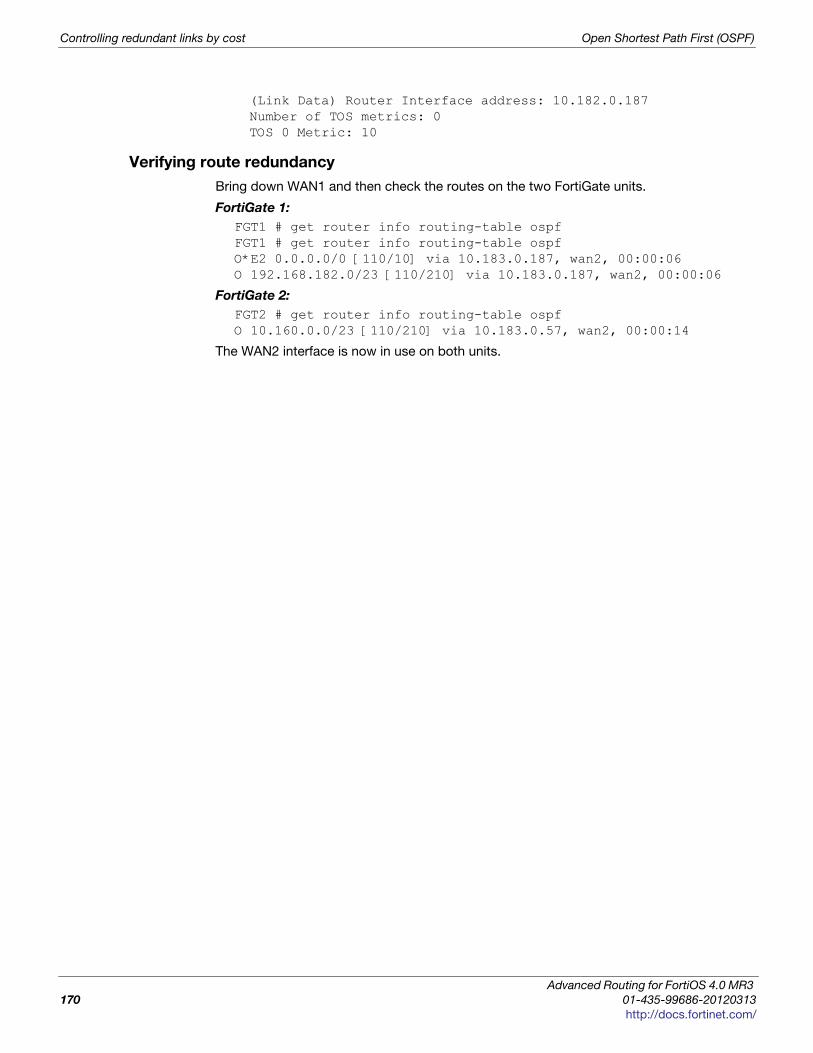
Controlling redundant links by cost Open Shortest Path First (OSPF)
(Link Data) Router Interface address: 10.182.0.187Number of TOS metrics: 0TOS 0 Metric: 10
Verifying route redundancy
Bring down WAN1 and then check the routes on the two FortiGate units.
FortiGate 1:
FGT1 # get router info routing-table ospfFGT1 # get router info routing-table ospfO*E2 0.0.0.0/0 [110/10] via 10.183.0.187, wan2, 00:00:06O 192.168.182.0/23 [110/210] via 10.183.0.187, wan2, 00:00:06
FortiGate 2:
FGT2 # get router info routing-table ospfO 10.160.0.0/23 [110/210] via 10.183.0.57, wan2, 00:00:14
The WAN2 interface is now in use on both units.
Advanced Routing for FortiOS 4.0 MR3
170 01-435-99686-20120313
http://docs.fortinet.com/
F o r t i O S H a n d b o o k
F
0
h
Intermediate System To Intermediate System Protocol (IS-IS)
This section describes the Intermediate System To Intermediate System Protocol (IS-IS).
The following topics are included in this section:
• IS-IS background and concepts
• Troubleshooting IS-IS
• Simple IS-IS example
IS-IS background and concepts
This section contains:
• Background
• How IS-IS works
Background
Intermediate System To Intermediate System Protocol (IS-IS) allows routing of ISO’s OSI
protocol stack Connectionless Network Service (CLNS).
IS-IS is an Interior Gateway Protocol (IGP). It it not intended to be used between
Autonomous Systems (ASes). IS-IS is a link state protocol and uses Dijstra’s algorithm to
find the best path, as does OSPF.
IS-IS was developed by Digital Equipment Corporation and later standardized by ISO in
1992 as ISO 19589 (see RFC 1142—note this RFC is different from the ISO version). At
roughly the same time the Internet Engineering Task Force developed OSPF. After the
initial version, IP support was added to IS-IS and this version is called Integrated IS-IS
(see RFC 1195).
While OSPF is more widely known, IS-IS is a viable alternative to OSPF in enterprise
networks and ISP infrastructures.
How IS-IS works
As one of the original modern dynamic routing protocols, IS-IS is straight forward. It’s
routing algorithm is not complex, there are some options to allow fine tuning, and its
straight forward to configure IS-IS on FortiGate units.
From RFC 1058:
Distance vector algorithms are based on the exchange of only a small amount of
information. Each entity (gateway or host) that participates in the routing protocol is
assumed to keep information about all of the destinations within the system.
Generally, information about all entities connected to one network is summarized by a
single entry, which describes the route to all destinations on that network.
ortiOS™ Handbook v3: Advanced Routing
1-435-99686-20120313 171
ttp://docs.fortinet.com/
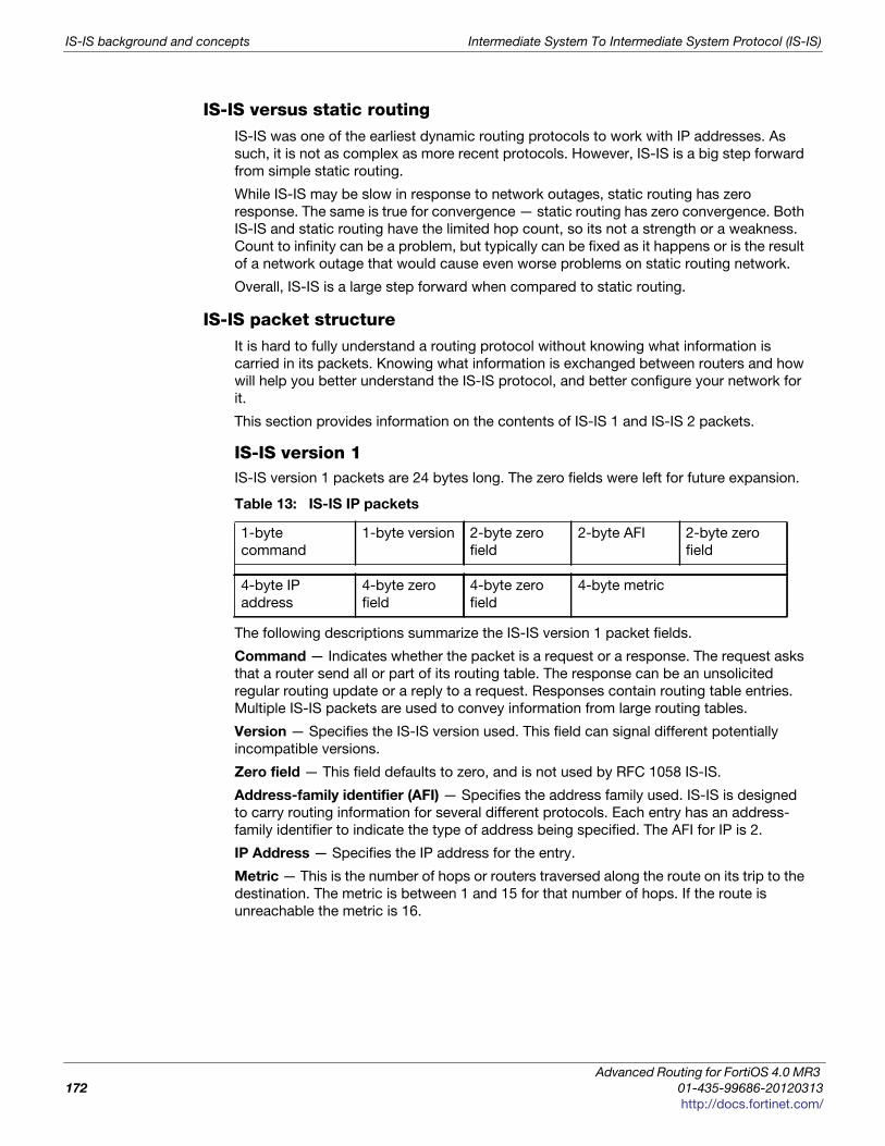
IS-IS background and concepts Intermediate System To Intermediate System Protocol (IS-IS)
IS-IS versus static routingIS-IS was one of the earliest dynamic routing protocols to work with IP addresses. As
such, it is not as complex as more recent protocols. However, IS-IS is a big step forward
from simple static routing.
While IS-IS may be slow in response to network outages, static routing has zero
response. The same is true for convergence — static routing has zero convergence. Both
IS-IS and static routing have the limited hop count, so its not a strength or a weakness.
Count to infinity can be a problem, but typically can be fixed as it happens or is the result
of a network outage that would cause even worse problems on static routing network.
Overall, IS-IS is a large step forward when compared to static routing.
IS-IS packet structureIt is hard to fully understand a routing protocol without knowing what information is
carried in its packets. Knowing what information is exchanged between routers and how
will help you better understand the IS-IS protocol, and better configure your network for
it.
This section provides information on the contents of IS-IS 1 and IS-IS 2 packets.
IS-IS version 1IS-IS version 1 packets are 24 bytes long. The zero fields were left for future expansion.
The following descriptions summarize the IS-IS version 1 packet fields.
Command — Indicates whether the packet is a request or a response. The request asks
that a router send all or part of its routing table. The response can be an unsolicited
regular routing update or a reply to a request. Responses contain routing table entries.
Multiple IS-IS packets are used to convey information from large routing tables.
Version — Specifies the IS-IS version used. This field can signal different potentially
incompatible versions.
Zero field — This field defaults to zero, and is not used by RFC 1058 IS-IS.
Address-family identifier (AFI) — Specifies the address family used. IS-IS is designed
to carry routing information for several different protocols. Each entry has an address-
family identifier to indicate the type of address being specified. The AFI for IP is 2.
IP Address — Specifies the IP address for the entry.
Metric — This is the number of hops or routers traversed along the route on its trip to the
destination. The metric is between 1 and 15 for that number of hops. If the route is
unreachable the metric is 16.
Table 13: IS-IS IP packets
1-byte
command
1-byte version 2-byte zero
field
2-byte AFI 2-byte zero
field
4-byte IP
address
4-byte zero
field
4-byte zero
field
4-byte metric
Advanced Routing for FortiOS 4.0 MR3
172 01-435-99686-20120313
http://docs.fortinet.com/

Intermediate System To Intermediate System Protocol (IS-IS) Troubleshooting IS-IS
F
0
h
IS-IS version 2IS-IS version 2 has more features that IS-IS 1 and this is reflected in its packets. IS-IS 2
packets are similar in format to IS-IS 1, but carry more information. Only one zero field
remains.
The following descriptions summarize the fields IS-IS 2 adds to the IS-IS IP header. The
other fields have been described above for IS-IS 1.
Unused — Has a value set to zero, and is intended for future use
Route tag — Provides a method for distinguishing between internal routes learned by IS-
IS and external routes learned from other protocols.
Subnet mask — Contains the subnet mask for the entry. If this field is zero, no subnet
mask has been specified for the entry.
Next hop — Indicates the IP address of the next hop to which packets for the entry
should be forwarded.
Troubleshooting IS-IS
This section is about troubleshooting IS-IS. For general troubleshooting information, see
the FortiOS Handbook Troubleshooting chapter.
This section includes:
• Routing Loops
• Split horizon and Poison reverse updates
Routing Loops
Normally in routing, a path between two addresses is chosen and traffic is routed along
that path from one address to the other. When there is a routing loop, that normal path
doubles back on itself creating a loop. When there are loops, the network has problems.
A routing loop happens when a normally functioning network has an outage, and one or
more routers are offline. When packets encounter this, an alternate route is attempted to
maneuver around the outage. During this phase it is possible for a route to be attempted
that involves going back a hop, and trying a different hop forward. If that hop forward is
blocked by the outage as well, a hop back and possibly the original hop forward may be
selected. You can see if this continues, how it can consume not only network bandwidth
but also many resources on those routers affected. The worst part is this situation will
continue until the network administrator changes the router settings, or the downed
routers come back online.
Routing loops’ effect on the networkIn addition to this “traffic jam” of routed packets, every time the routing table for a router
changes that router sends an update out to all of the IS-IS routers connected to it. In a
network loop, its possible for a router to change its routes very quickly as it tries and fails
along these new routes. This can quickly result in a flood of updates being sent out,
which can effectively grind the network to a halt until the problem is fixed.
Table 14: IS-IS 2 packets
1-byte
command
1-byte
version
2-byte
unused
2-byte
AFI
2-byte
route
tag
4-byte IP
address
4-byte
subnet
4-byte
next
hop
4-byte
metric
ortiOS™ Handbook v3: Advanced Routing
1-435-99686-20120313 173
ttp://docs.fortinet.com/
Troubleshooting IS-IS Intermediate System To Intermediate System Protocol (IS-IS)
How can you spot a routing loopAny time network traffic slows down, you will be asking yourself if it is a network loop or
not. Often slowdowns are normal, they are not a full stoppage, and normal traffic resumes
in a short period of time.
If the slow down is a full halt of traffic or a major slowdown does not return to normal
quickly, you need to do serious troubleshooting quickly.
Some methods to troubleshoot your outage include:
• Check your logs
• Use SNMP network monitoring
• Use dead gateway detection and e-mail alerts
• Look at the packet flow
If you aren’t running SNMP, dead gateway detection, or you have non-Fortinet routers in
your network, you can use networking tools such as ping and traceroute to define the
outage on your network and begin to fix it.
Check your logsIf your routers log events to a central location, it can be easy to check the logs for your
network for any outages.
On your FortiGate unit, go to Log & Report > Log & Archive Access. You will want to look
at both event logs and traffic logs. Events to look for will generally fall under CPU and
memory usage, interfaces going offline (due to dead gateway detection), and other
similar system events.
Once you have found and fixed your network problem, you can go back to the logs and
create a report to better see how things developed during the problem. This type of
forensics analysis can better help you prepare for next time.
Use SNMP network monitoringIf your network had no problems one minute and slows to a halt the next, chances are
something changed to cause that problem. Most of the time an offline router is the cause,
and once you find that router and bring it back online, things will return to normal.
If you can enable a hardware monitoring system such as SNMP or sFlow on your routers,
you can be notified of the outage and where it is exactly as soon as it happens.
Ideally you can configure SNMP on all your FortiGate routers and be alerted to all
outages as they occur.
To use SNMP to detect potential routing loops
1 Go to System > Config > SNMP.
2 Enable SNMP Agent.
3 Optionally enter the Description, Location, and Contact information for this device for
easier location of the problem report.
4 In either SNMP v1/v2c section or SNMP v3 section, as appropriate, select Create
New.
5 Enter the Community Name that you want to use.
6 In Hosts, select Add to add an IP address where you will be monitoring the FortiGate
unit. You can add up to 8 different addresses.
7 Ensure that ports 161 and 162 (SNMP queries and traps) are allowed through your
security policies.
Advanced Routing for FortiOS 4.0 MR3
174 01-435-99686-20120313
http://docs.fortinet.com/
Intermediate System To Intermediate System Protocol (IS-IS) Troubleshooting IS-IS
F
0
h
8 In SNMP Event, select the events you want to be notified of. For routing loops this
should include CPU Overusage, Memory Low, and possibly Log disk space low. If
there are problems, the log will be filling up quickly, and the FortiGate unit’s resources
will be overused.
9 Select OK.
10 Configure SNMP host (manager) software on your administration computer. This will
monitor the SNMP information sent out by the FortiGate unit. Typically you can
configure this software to alert you to outages or CPU spikes that may indicate a
routing loop.
Use dead gateway detection and e-mail alertsAnother tool available to you on FortiGate units is the dead gateway detection. This
feature allows the FortiGate unit to ping a gateway at regular intervals to ensure it is
online and working. When the gateway is not accessible, that interface is marked as
down.
To detect possible routing loops with dead gateway detection and e-mail alerts
1 To configure dead gateway detection, go to Router > Static > Settings and select
Create New.
2 Set the Ping Interval (how often to send a ping), and Failover Threshold (how many
lost pings is considered a failure). A smaller interval and smaller number of lost pings
will result in faster detection, but will create more traffic on your network.
3 To configure interface status change notification, go to Log&Report >Log Config >
Alert E-mail.
4 After you enter your email details, select the events you want to be alerted about — in
our case Configuration changes. You may also want to log CPU and Memory usage as
a network outage will cause your CPU activity to spike.
After this configuration, when this interface on the FortiGate unit cannot connect to the
next router, the FortiGate unit will bring down the interface and alert you with an email to
the outage.
Look at the packet flowIf you want to see what is happening on your network, look at the packets travelling on
the network. In this situation, you are looking for routes that have metrics higher than 15
as that indicates they are unreachable. Ideally if you debug the flow of the packets, and
record the routes that are unreachable, you can create an accurate picture of the network
outage.
Action to take on discovering a routing loopOnce you have mapped the problem on your network, and determined it is in fact a
routing loop there are a number of steps to take in correcting it.
1 Get any offline routers back online. This may be a simple reboot, or you may have to
replace hardware. Often this first step will restore your network to its normal
operation, once the routing tables finish being updated.
If you have VDOMs configured, you will have to enter the basic SMTP server information
in the Global section, and the rest of the configuration within the VDOM that includes
this interface.
ortiOS™ Handbook v3: Advanced Routing
1-435-99686-20120313 175
ttp://docs.fortinet.com/
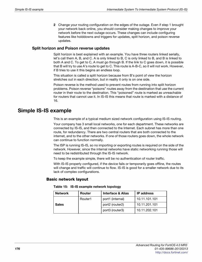
Simple IS-IS example Intermediate System To Intermediate System Protocol (IS-IS)
2 Change your routing configuration on the edges of the outage. Even if step 1 brought
your network back online, you should consider making changes to improve your
network before the next outage occurs. These changes can include configuring
features like holddowns and triggers for updates, split horizon, and poison reverse
updates.
Split horizon and Poison reverse updates
Split horizon is best explained with an example. You have three routers linked serially,
let’s call them A, B, and C. A is only linked to B, C is only linked to B, and B is linked to
both A and C. To get to C, A must go through B. If the link to C goes down, it is possible
that B will try to use A’s route to get to C. This route is A-B-C, so it will not work. However,
if B tries to use it this begins an endless loop.
This situation is called a split horizon because from B’s point of view the horizon
stretches out in each direction, but in reality it only is on one side.
Poison reverse is the method used to prevent routes from running into split horizon
problems. Poison reverse “poisons” routes away from the destination that use the current
router in their route to the destination. This “poisoned” route is marked as unreachable
for routers that cannot use it. In IS-IS this means that route is marked with a distance of
16.
Simple IS-IS example
This is an example of a typical medium sized network configuration using IS-IS routing.
Your company has 3 small local networks, one for each department. These networks are
connected by IS-IS, and then connected to the Internet. Each subnet has more than one
route, for redundancy. There are two central routers that are both connected to the
internet, and to the other networks. If one of those routers goes down, the whole network
can continue to function normally.
The ISP is running IS-IS, so no importing or exporting routes is required on the side of the
network. However, since the internal networks have static networking running those will
need to be redistributed through the IS-IS network.
To keep the example simple, there will be no authentication of router traffic.
With IS-IS properly configured, if the device fails or temporarily goes offline, the routes
will change and traffic will continue to flow. IS-IS is good for a smaller network due to its
lack of complex configurations.
Basic network layout
Table 15: IS-IS example network topology
Network Router Interface & Alias IP address
Sales
Router1 port1 (internal) 10.11.101.101
port2 (router2) 10.11.201.101
port3 (router3) 10.11.202.101
Advanced Routing for FortiOS 4.0 MR3
176 01-435-99686-20120313
http://docs.fortinet.com/
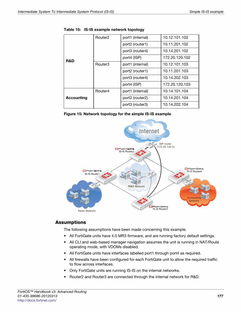
Intermediate System To Intermediate System Protocol (IS-IS) Simple IS-IS example
F
0
h
Figure 15: Network topology for the simple IS-IS example
AssumptionsThe following assumptions have been made concerning this example.
• All FortiGate units have 4.0 MR3 firmware, and are running factory default settings.
• All CLI and web-based manager navigation assumes the unit is running in NAT/Route
operating mode, with VDOMs disabled.
• All FortiGate units have interfaces labelled port1 through port4 as required.
• All firewalls have been configured for each FortiGate unit to allow the required traffic
to flow across interfaces.
• Only FortiGate units are running IS-IS on the internal networks.
• Router2 and Router3 are connected through the internal network for R&D.
R&D
Router2 port1 (internal) 10.12.101.102
port2 (router1) 10.11.201.102
port3 (router4) 10.14.201.102
port4 (ISP) 172.20.120.102
Router3 port1 (internal) 10.12.101.103
port2 (router1) 10.11.201.103
port3 (router4) 10.14.202.103
port4 (ISP) 172.20.120.103
Accounting
Router4 port1 (internal) 10.14.101.104
port2 (router2) 10.14.201.104
port3 (router3) 10.14.202.104
Table 15: IS-IS example network topology
ISP router (172.20.120.5)
IS-IS Router1
IS-IS Router2
Sales Network
IS-IS Router4
AccountingNetwork
R&D Network
IS-IS Router3IS
outer1IS-IS
outer2
ortiOS™ Handbook v3: Advanced Routing
1-435-99686-20120313 177
ttp://docs.fortinet.com/
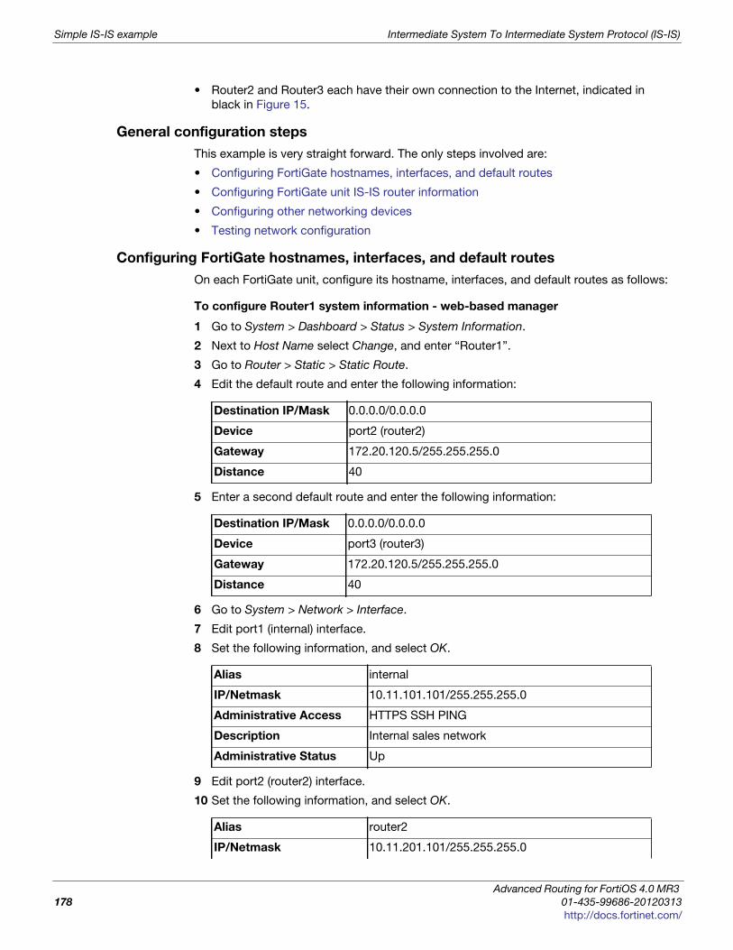
Simple IS-IS example Intermediate System To Intermediate System Protocol (IS-IS)
• Router2 and Router3 each have their own connection to the Internet, indicated in
black in Figure 15.
General configuration steps
This example is very straight forward. The only steps involved are:
• Configuring FortiGate hostnames, interfaces, and default routes
• Configuring FortiGate unit IS-IS router information
• Configuring other networking devices
• Testing network configuration
Configuring FortiGate hostnames, interfaces, and default routes
On each FortiGate unit, configure its hostname, interfaces, and default routes as follows:
To configure Router1 system information - web-based manager
1 Go to System > Dashboard > Status > System Information.
2 Next to Host Name select Change, and enter “Router1”.
3 Go to Router > Static > Static Route.
4 Edit the default route and enter the following information:
5 Enter a second default route and enter the following information:
6 Go to System > Network > Interface.
7 Edit port1 (internal) interface.
8 Set the following information, and select OK.
9 Edit port2 (router2) interface.
10 Set the following information, and select OK.
Destination IP/Mask 0.0.0.0/0.0.0.0
Device port2 (router2)
Gateway 172.20.120.5/255.255.255.0
Distance 40
Destination IP/Mask 0.0.0.0/0.0.0.0
Device port3 (router3)
Gateway 172.20.120.5/255.255.255.0
Distance 40
Alias internal
IP/Netmask 10.11.101.101/255.255.255.0
Administrative Access HTTPS SSH PING
Description Internal sales network
Administrative Status Up
Alias router2
IP/Netmask 10.11.201.101/255.255.255.0
Advanced Routing for FortiOS 4.0 MR3
178 01-435-99686-20120313
http://docs.fortinet.com/
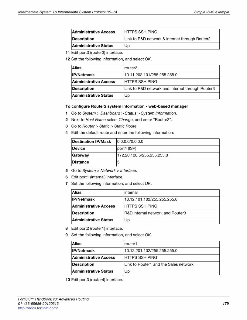
Intermediate System To Intermediate System Protocol (IS-IS) Simple IS-IS example
F
0
h
11 Edit port3 (router3) interface.
12 Set the following information, and select OK.
To configure Router2 system information - web-based manager
1 Go to System > Dashboard > Status > System Information.
2 Next to Host Name select Change, and enter “Router2”.
3 Go to Router > Static > Static Route.
4 Edit the default route and enter the following information:
5 Go to System > Network > Interface.
6 Edit port1 (internal) interface.
7 Set the following information, and select OK.
8 Edit port2 (router1) interface.
9 Set the following information, and select OK.
10 Edit port3 (router4) interface.
Administrative Access HTTPS SSH PING
Description Link to R&D network & internet through Router2
Administrative Status Up
Alias router3
IP/Netmask 10.11.202.101/255.255.255.0
Administrative Access HTTPS SSH PING
Description Link to R&D network and internet through Router3
Administrative Status Up
Destination IP/Mask 0.0.0.0/0.0.0.0
Device port4 (ISP)
Gateway 172.20.120.5/255.255.255.0
Distance 5
Alias internal
IP/Netmask 10.12.101.102/255.255.255.0
Administrative Access HTTPS SSH PING
Description R&D internal network and Router3
Administrative Status Up
Alias router1
IP/Netmask 10.12.201.102/255.255.255.0
Administrative Access HTTPS SSH PING
Description Link to Router1 and the Sales network
Administrative Status Up
ortiOS™ Handbook v3: Advanced Routing
1-435-99686-20120313 179
ttp://docs.fortinet.com/
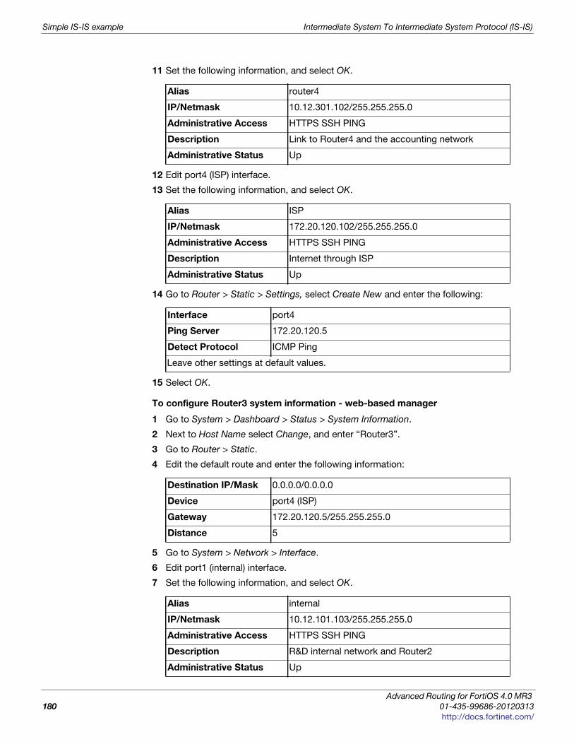
Simple IS-IS example Intermediate System To Intermediate System Protocol (IS-IS)
11 Set the following information, and select OK.
12 Edit port4 (ISP) interface.
13 Set the following information, and select OK.
14 Go to Router > Static > Settings, select Create New and enter the following:
15 Select OK.
To configure Router3 system information - web-based manager
1 Go to System > Dashboard > Status > System Information.
2 Next to Host Name select Change, and enter “Router3”.
3 Go to Router > Static.
4 Edit the default route and enter the following information:
5 Go to System > Network > Interface.
6 Edit port1 (internal) interface.
7 Set the following information, and select OK.
Alias router4
IP/Netmask 10.12.301.102/255.255.255.0
Administrative Access HTTPS SSH PING
Description Link to Router4 and the accounting network
Administrative Status Up
Alias ISP
IP/Netmask 172.20.120.102/255.255.255.0
Administrative Access HTTPS SSH PING
Description Internet through ISP
Administrative Status Up
Interface port4
Ping Server 172.20.120.5
Detect Protocol ICMP Ping
Leave other settings at default values.
Destination IP/Mask 0.0.0.0/0.0.0.0
Device port4 (ISP)
Gateway 172.20.120.5/255.255.255.0
Distance 5
Alias internal
IP/Netmask 10.12.101.103/255.255.255.0
Administrative Access HTTPS SSH PING
Description R&D internal network and Router2
Administrative Status Up
Advanced Routing for FortiOS 4.0 MR3
180 01-435-99686-20120313
http://docs.fortinet.com/
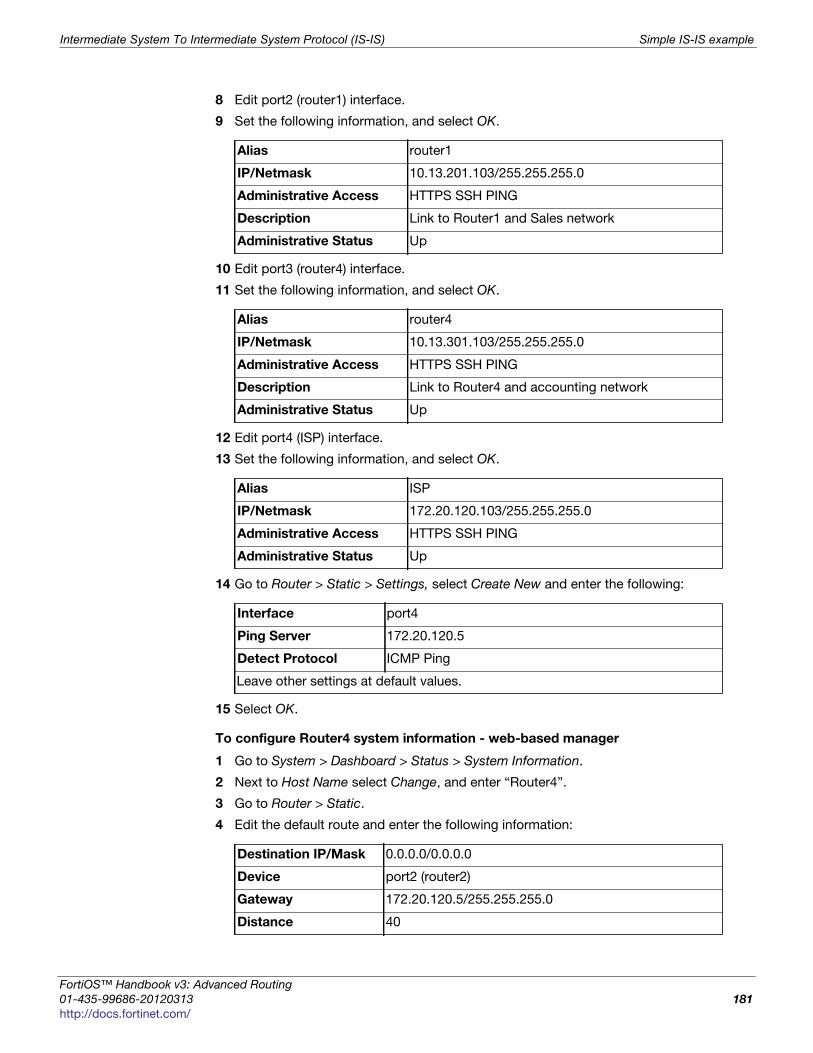
Intermediate System To Intermediate System Protocol (IS-IS) Simple IS-IS example
F
0
h
8 Edit port2 (router1) interface.
9 Set the following information, and select OK.
10 Edit port3 (router4) interface.
11 Set the following information, and select OK.
12 Edit port4 (ISP) interface.
13 Set the following information, and select OK.
14 Go to Router > Static > Settings, select Create New and enter the following:
15 Select OK.
To configure Router4 system information - web-based manager
1 Go to System > Dashboard > Status > System Information.
2 Next to Host Name select Change, and enter “Router4”.
3 Go to Router > Static.
4 Edit the default route and enter the following information:
Alias router1
IP/Netmask 10.13.201.103/255.255.255.0
Administrative Access HTTPS SSH PING
Description Link to Router1 and Sales network
Administrative Status Up
Alias router4
IP/Netmask 10.13.301.103/255.255.255.0
Administrative Access HTTPS SSH PING
Description Link to Router4 and accounting network
Administrative Status Up
Alias ISP
IP/Netmask 172.20.120.103/255.255.255.0
Administrative Access HTTPS SSH PING
Administrative Status Up
Interface port4
Ping Server 172.20.120.5
Detect Protocol ICMP Ping
Leave other settings at default values.
Destination IP/Mask 0.0.0.0/0.0.0.0
Device port2 (router2)
Gateway 172.20.120.5/255.255.255.0
Distance 40
ortiOS™ Handbook v3: Advanced Routing
1-435-99686-20120313 181
ttp://docs.fortinet.com/
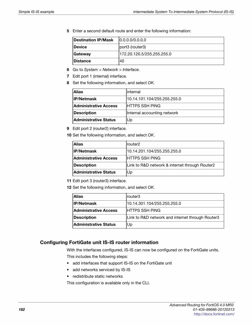
Simple IS-IS example Intermediate System To Intermediate System Protocol (IS-IS)
5 Enter a second default route and enter the following information:
6 Go to System > Network > Interface.
7 Edit port 1 (internal) interface.
8 Set the following information, and select OK.
9 Edit port 2 (router2) interface.
10 Set the following information, and select OK.
11 Edit port 3 (router3) interface.
12 Set the following information, and select OK.
Configuring FortiGate unit IS-IS router information
With the interfaces configured, IS-IS can now be configured on the FortiGate units.
This includes the following steps:
• add interfaces that support IS-IS on the FortiGate unit
• add networks serviced by IS-IS
• redistribute static networks
This configuration is available only in the CLI.
Destination IP/Mask 0.0.0.0/0.0.0.0
Device port3 (router3)
Gateway 172.20.120.5/255.255.255.0
Distance 40
Alias internal
IP/Netmask 10.14.101.104/255.255.255.0
Administrative Access HTTPS SSH PING
Description Internal accounting network
Administrative Status Up
Alias router2
IP/Netmask 10.14.201.104/255.255.255.0
Administrative Access HTTPS SSH PING
Description Link to R&D network & internet through Router2
Administrative Status Up
Alias router3
IP/Netmask 10.14.301.104/255.255.255.0
Administrative Access HTTPS SSH PING
Description Link to R&D network and internet through Router3
Administrative Status Up
Advanced Routing for FortiOS 4.0 MR3
182 01-435-99686-20120313
http://docs.fortinet.com/
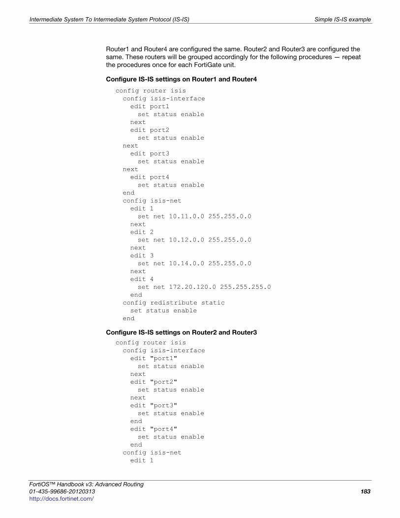
Intermediate System To Intermediate System Protocol (IS-IS) Simple IS-IS example
F
0
h
Router1 and Router4 are configured the same. Router2 and Router3 are configured the
same. These routers will be grouped accordingly for the following procedures — repeat
the procedures once for each FortiGate unit.
Configure IS-IS settings on Router1 and Router4
config router isisconfig isis-interfaceedit port1set status enable
nextedit port2set status enable
nextedit port3set status enable
nextedit port4set status enable
endconfig isis-netedit 1set net 10.11.0.0 255.255.0.0
nextedit 2set net 10.12.0.0 255.255.0.0
nextedit 3set net 10.14.0.0 255.255.0.0
nextedit 4set net 172.20.120.0 255.255.255.0
endconfig redistribute staticset status enable
end
Configure IS-IS settings on Router2 and Router3
config router isisconfig isis-interfaceedit "port1"set status enable
nextedit "port2"set status enable
nextedit "port3"set status enable
endedit "port4"set status enable
endconfig isis-netedit 1
ortiOS™ Handbook v3: Advanced Routing
1-435-99686-20120313 183
ttp://docs.fortinet.com/
Simple IS-IS example Intermediate System To Intermediate System Protocol (IS-IS)
set net 10.11.0.0 255.255.0.0nextedit 2set net 10.12.0.0 255.255.0.0
nextedit 3set net 10.14.0.0 255.255.0.0
nextedit 4set net 172.20.120.0 255.255.255.0
endconfig redistribute "static"set status enable
end
Configuring other networking devices
In this example there are two groups of other devices on the the network — internal
devices, and the ISP.
The first is the internal network devices on the Sales, R&D, and Accounting networks.
This includes simple static routers, computers, printers and other network devices. Once
the FortiGate units are configured, the internal static routers need to be configured using
the internal network IP addresses. Otherwise there should be no configuration required.
The second group of devices is the ISP. This consists of the IS-IS router the FortiGate
routers 2 and 3 connect to. You need to contact your ISP and ensure they have your
information for your network such as the IP addresses of the connecting IS-IS routers,
what version of IS-IS your network supports, and what authentication (if any) is used.
Testing network configuration
Once the network has been configured, you need to test that it works as expected.
The two series of tests you need to run are to test the internal networks can communicate
with each other, and that the internal networks can reach the internet.
Use ping, traceroute, and other networking tools to run these tests.
If you encounter problems, for troubleshooting help consult “Troubleshooting IS-IS” on
page 173.
Advanced Routing for FortiOS 4.0 MR3
184 01-435-99686-20120313
http://docs.fortinet.com/
F o r t i O S H a n d b o o k
F
0
h
Router ReferenceThis section introduces you to the web-based manager Router menu.
This section contains the following topics:
• Static
• Dynamic
• Monitor
Static
The Static menu provides settings for configuring both static and policy routes. A static
route causes packets to be forwarded to a destination other than the factory configured
default gateway. A policy route allows you to redirect traffic away from a static route, and
can be useful when you want to route certain type of network traffic differently.
The factory configured static default route provides you with a starting point to configure
the default gateway. You must either edit the factory configured static default route to
specify a different default gateway for the unit, or delete the factory configured route and
specify your own static default route that points to the default gateway for the unit.
Static routes are defined manually and control traffic exiting from the unit—you can
specify through which interface the packet will leave and to which device the packet
should be routed.
Route policies or policy routes, specify additional criteria for examining the properties of
incoming packets. By using route policies, you can configure the unit to route packets
based on the IP source and destination addresses in packet headers and other criteria
such as on which interface the packet was received and which protocol (service) and port
are being used to transport the packet.
The following topics are included in this section:
• Static Route
• Policy Route
• Settings
Static Route
Static routes are configured by defining the destination IP address and netmask of
packets that you intend the unit to intercept, and by specifying a (gateway) IP address for
those packets. The gateway address specifies the next-hop router to which traffic will be
routed.
The word “unit” refers to the FortiGate unit. The words “FortiGate unit” are used when
talking about different Fortinet products in one sentence. For example, “The Central
Management menu provides the option of remotely managing your FortiGate unit by a
FortiManager unit.”
ortiOS™ Handbook v3: Advanced Routing
1-435-99686-20120313 185
ttp://docs.fortinet.com/
Static Router Reference
The Static Route page displays a list of routes that the unit compares to packet headers
in order to route packets. Initially, the list contains the factory configured static default
route. For more information, see “Default route and default gateway” on page 188. You
can add new entries manually.
When you add a static route to the Static Route list, the unit performs a check to
determine whether a matching route and destination already exist in the FortiGate routing
table. If no match is found, the unit adds the route to the routing table.
When IPv6 is enabled in the web-based manager, IPv6 routes are visible on the Static
Route list and you can select IPv6 when creating a new static route. Otherwise, IPv6
routes are not displayed.
Advanced Routing for FortiOS 4.0 MR3
186 01-435-99686-20120313
http://docs.fortinet.com/
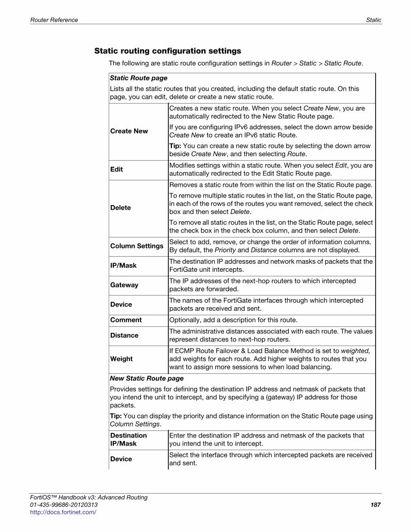
Router Reference Static
F
0
h
Static routing configuration settingsThe following are static route configuration settings in Router > Static > Static Route.
Static Route page
Lists all the static routes that you created, including the default static route. On this
page, you can edit, delete or create a new static route.
Create New
Creates a new static route. When you select Create New, you are
automatically redirected to the New Static Route page.
If you are configuring IPv6 addresses, select the down arrow beside
Create New to create an IPv6 static Route.
Tip: You can create a new static route by selecting the down arrow
beside Create New, and then selecting Route.
Edit Modifies settings within a static route. When you select Edit, you are
automatically redirected to the Edit Static Route page.
Delete
Removes a static route from within the list on the Static Route page.
To remove multiple static routes in the list, on the Static Route page,
in each of the rows of the routes you want removed, select the check
box and then select Delete.
To remove all static routes in the list, on the Static Route page, select
the check box in the check box column, and then select Delete.
Column SettingsSelect to add, remove, or change the order of information columns.
By default, the Priority and Distance columns are not displayed.
IP/MaskThe destination IP addresses and network masks of packets that the
FortiGate unit intercepts.
GatewayThe IP addresses of the next-hop routers to which intercepted
packets are forwarded.
DeviceThe names of the FortiGate interfaces through which intercepted
packets are received and sent.
Comment Optionally, add a description for this route.
DistanceThe administrative distances associated with each route. The values
represent distances to next-hop routers.
Weight
If ECMP Route Failover & Load Balance Method is set to weighted,
add weights for each route. Add higher weights to routes that you
want to assign more sessions to when load balancing.
New Static Route page
Provides settings for defining the destination IP address and netmask of packets that
you intend the unit to intercept, and by specifying a (gateway) IP address for those
packets.
Tip: You can display the priority and distance information on the Static Route page using
Column Settings.
Destination
IP/Mask
Enter the destination IP address and netmask of the packets that
you intend the unit to intercept.
DeviceSelect the interface through which intercepted packets are received
and sent.
ortiOS™ Handbook v3: Advanced Routing
1-435-99686-20120313 187
ttp://docs.fortinet.com/
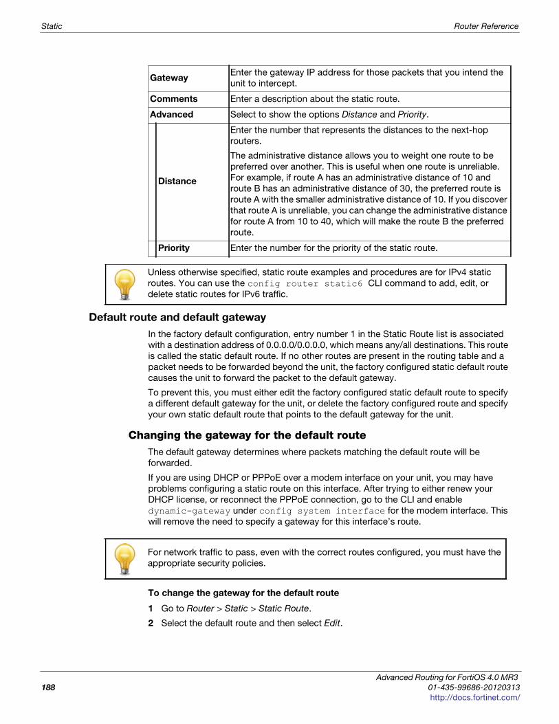
Static Router Reference
Default route and default gateway
In the factory default configuration, entry number 1 in the Static Route list is associated
with a destination address of 0.0.0.0/0.0.0.0, which means any/all destinations. This route
is called the static default route. If no other routes are present in the routing table and a
packet needs to be forwarded beyond the unit, the factory configured static default route
causes the unit to forward the packet to the default gateway.
To prevent this, you must either edit the factory configured static default route to specify
a different default gateway for the unit, or delete the factory configured route and specify
your own static default route that points to the default gateway for the unit.
Changing the gateway for the default routeThe default gateway determines where packets matching the default route will be
forwarded.
If you are using DHCP or PPPoE over a modem interface on your unit, you may have
problems configuring a static route on this interface. After trying to either renew your
DHCP license, or reconnect the PPPoE connection, go to the CLI and enable
dynamic-gateway under config system interface for the modem interface. This
will remove the need to specify a gateway for this interface’s route.
To change the gateway for the default route
1 Go to Router > Static > Static Route.
2 Select the default route and then select Edit.
GatewayEnter the gateway IP address for those packets that you intend the
unit to intercept.
Comments Enter a description about the static route.
Advanced Select to show the options Distance and Priority.
Distance
Enter the number that represents the distances to the next-hop
routers.
The administrative distance allows you to weight one route to be
preferred over another. This is useful when one route is unreliable.
For example, if route A has an administrative distance of 10 and
route B has an administrative distance of 30, the preferred route is
route A with the smaller administrative distance of 10. If you discover
that route A is unreliable, you can change the administrative distance
for route A from 10 to 40, which will make the route B the preferred
route.
Priority Enter the number for the priority of the static route.
Unless otherwise specified, static route examples and procedures are for IPv4 static
routes. You can use the config router static6 CLI command to add, edit, or
delete static routes for IPv6 traffic.
For network traffic to pass, even with the correct routes configured, you must have the
appropriate security policies.
Advanced Routing for FortiOS 4.0 MR3
188 01-435-99686-20120313
http://docs.fortinet.com/
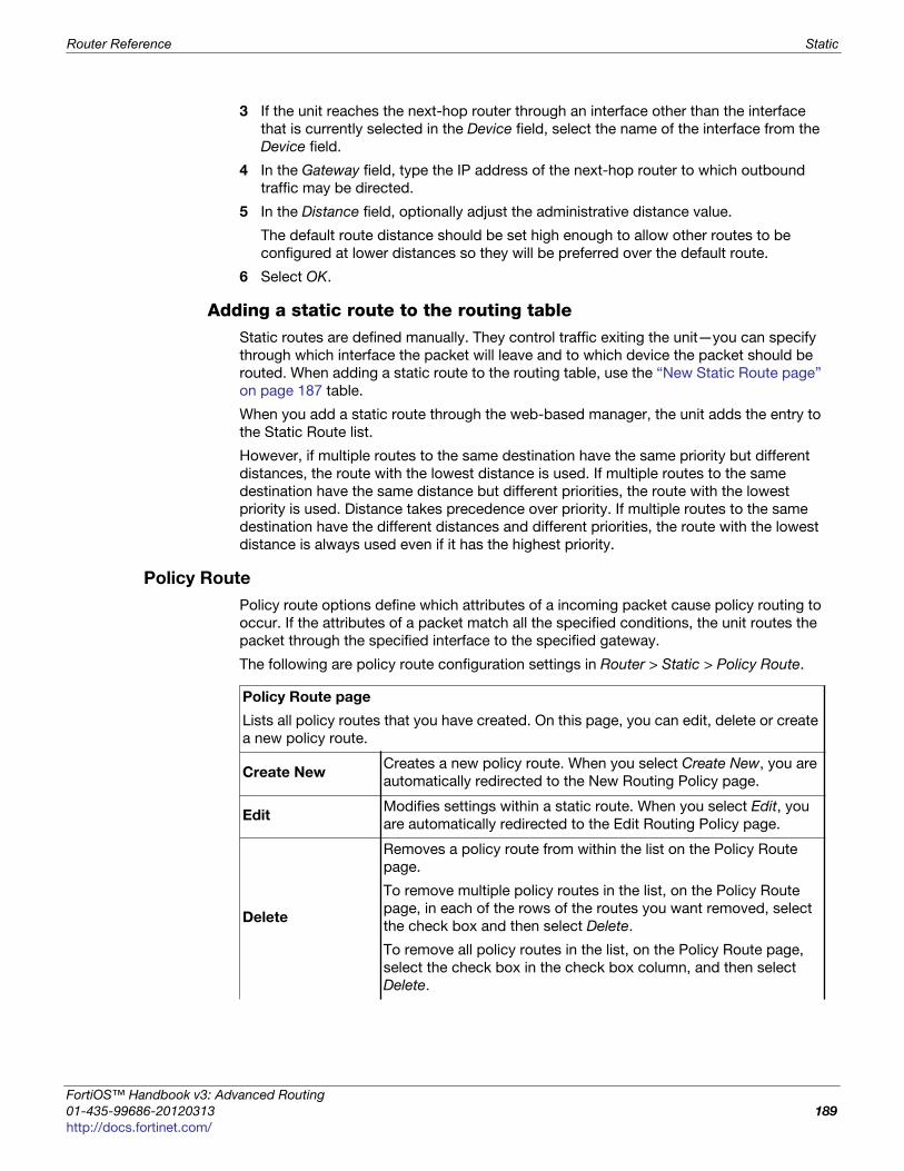
Router Reference Static
F
0
h
3 If the unit reaches the next-hop router through an interface other than the interface
that is currently selected in the Device field, select the name of the interface from the
Device field.
4 In the Gateway field, type the IP address of the next-hop router to which outbound
traffic may be directed.
5 In the Distance field, optionally adjust the administrative distance value.
The default route distance should be set high enough to allow other routes to be
configured at lower distances so they will be preferred over the default route.
6 Select OK.
Adding a static route to the routing table Static routes are defined manually. They control traffic exiting the unit—you can specify
through which interface the packet will leave and to which device the packet should be
routed. When adding a static route to the routing table, use the “New Static Route page”
on page 187 table.
When you add a static route through the web-based manager, the unit adds the entry to
the Static Route list.
However, if multiple routes to the same destination have the same priority but different
distances, the route with the lowest distance is used. If multiple routes to the same
destination have the same distance but different priorities, the route with the lowest
priority is used. Distance takes precedence over priority. If multiple routes to the same
destination have the different distances and different priorities, the route with the lowest
distance is always used even if it has the highest priority.
Policy Route
Policy route options define which attributes of a incoming packet cause policy routing to
occur. If the attributes of a packet match all the specified conditions, the unit routes the
packet through the specified interface to the specified gateway.
The following are policy route configuration settings in Router > Static > Policy Route.
Policy Route page
Lists all policy routes that you have created. On this page, you can edit, delete or create
a new policy route.
Create NewCreates a new policy route. When you select Create New, you are
automatically redirected to the New Routing Policy page.
EditModifies settings within a static route. When you select Edit, you
are automatically redirected to the Edit Routing Policy page.
Delete
Removes a policy route from within the list on the Policy Route
page.
To remove multiple policy routes in the list, on the Policy Route
page, in each of the rows of the routes you want removed, select
the check box and then select Delete.
To remove all policy routes in the list, on the Policy Route page,
select the check box in the check box column, and then select
Delete.
ortiOS™ Handbook v3: Advanced Routing
1-435-99686-20120313 189
ttp://docs.fortinet.com/
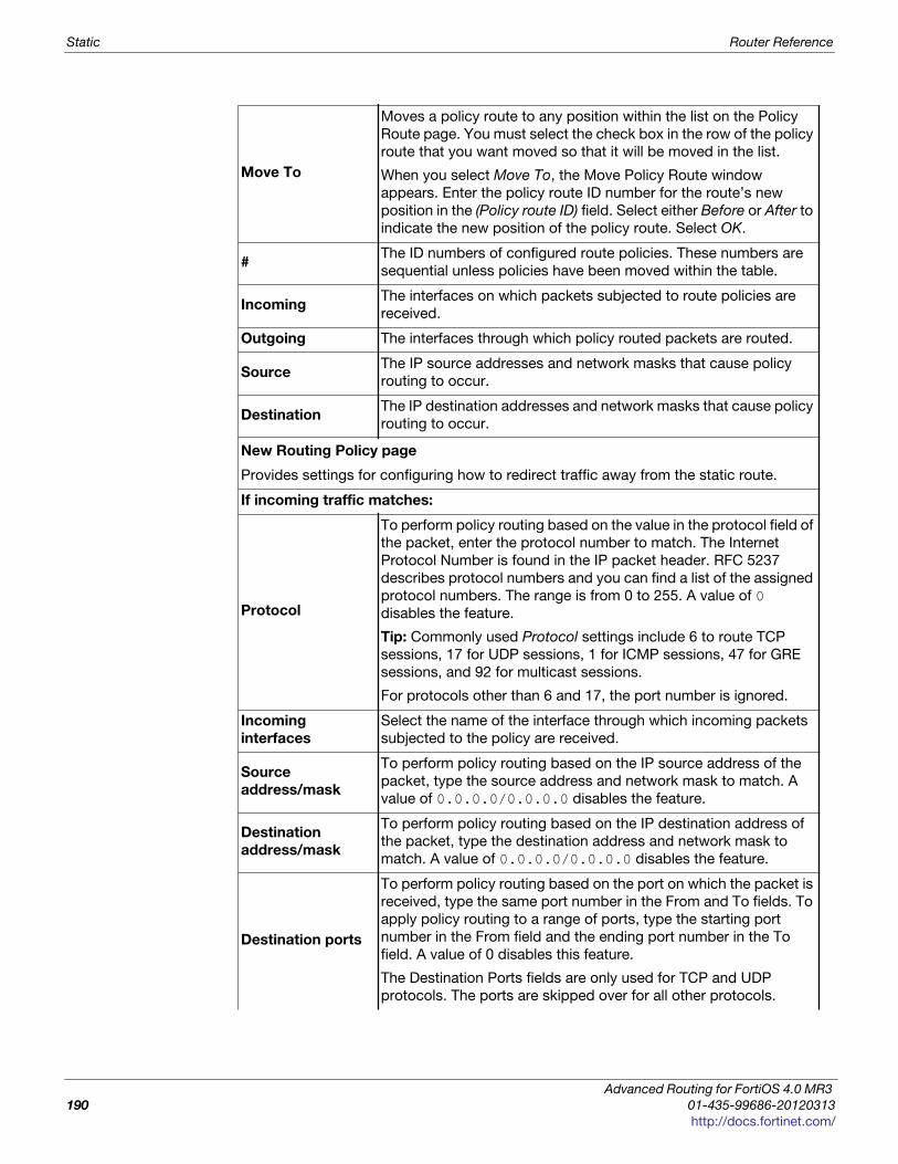
Static Router Reference
Move To
Moves a policy route to any position within the list on the Policy
Route page. You must select the check box in the row of the policy
route that you want moved so that it will be moved in the list.
When you select Move To, the Move Policy Route window
appears. Enter the policy route ID number for the route’s new
position in the (Policy route ID) field. Select either Before or After to
indicate the new position of the policy route. Select OK.
#The ID numbers of configured route policies. These numbers are
sequential unless policies have been moved within the table.
IncomingThe interfaces on which packets subjected to route policies are
received.
Outgoing The interfaces through which policy routed packets are routed.
Source The IP source addresses and network masks that cause policy
routing to occur.
DestinationThe IP destination addresses and network masks that cause policy
routing to occur.
New Routing Policy page
Provides settings for configuring how to redirect traffic away from the static route.
If incoming traffic matches:
Protocol
To perform policy routing based on the value in the protocol field of
the packet, enter the protocol number to match. The Internet
Protocol Number is found in the IP packet header. RFC 5237
describes protocol numbers and you can find a list of the assigned
protocol numbers. The range is from 0 to 255. A value of 0
disables the feature.
Tip: Commonly used Protocol settings include 6 to route TCP
sessions, 17 for UDP sessions, 1 for ICMP sessions, 47 for GRE
sessions, and 92 for multicast sessions.
For protocols other than 6 and 17, the port number is ignored.
Incoming
interfaces
Select the name of the interface through which incoming packets
subjected to the policy are received.
Source
address/mask
To perform policy routing based on the IP source address of the
packet, type the source address and network mask to match. A
value of 0.0.0.0/0.0.0.0 disables the feature.
Destination
address/mask
To perform policy routing based on the IP destination address of
the packet, type the destination address and network mask to
match. A value of 0.0.0.0/0.0.0.0 disables the feature.
Destination ports
To perform policy routing based on the port on which the packet is
received, type the same port number in the From and To fields. To
apply policy routing to a range of ports, type the starting port
number in the From field and the ending port number in the To
field. A value of 0 disables this feature.
The Destination Ports fields are only used for TCP and UDP
protocols. The ports are skipped over for all other protocols.
Advanced Routing for FortiOS 4.0 MR3
190 01-435-99686-20120313
http://docs.fortinet.com/
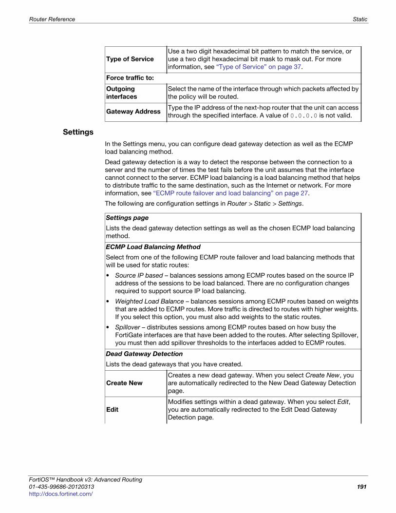
Router Reference Static
F
0
h
Settings
In the Settings menu, you can configure dead gateway detection as well as the ECMP
load balancing method.
Dead gateway detection is a way to detect the response between the connection to a
server and the number of times the test fails before the unit assumes that the interface
cannot connect to the server. ECMP load balancing is a load balancing method that helps
to distribute traffic to the same destination, such as the Internet or network. For more
information, see “ECMP route failover and load balancing” on page 27.
The following are configuration settings in Router > Static > Settings.
Type of Service
Use a two digit hexadecimal bit pattern to match the service, or
use a two digit hexadecimal bit mask to mask out. For more
information, see “Type of Service” on page 37.
Force traffic to:
Outgoing
interfaces
Select the name of the interface through which packets affected by
the policy will be routed.
Gateway AddressType the IP address of the next-hop router that the unit can access
through the specified interface. A value of 0.0.0.0 is not valid.
Settings page
Lists the dead gateway detection settings as well as the chosen ECMP load balancing
method.
ECMP Load Balancing Method
Select from one of the following ECMP route failover and load balancing methods that
will be used for static routes:
• Source IP based – balances sessions among ECMP routes based on the source IP
address of the sessions to be load balanced. There are no configuration changes
required to support source IP load balancing.
• Weighted Load Balance – balances sessions among ECMP routes based on weights
that are added to ECMP routes. More traffic is directed to routes with higher weights.
If you select this option, you must also add weights to the static routes.
• Spillover – distributes sessions among ECMP routes based on how busy the
FortiGate interfaces are that have been added to the routes. After selecting Spillover,
you must then add spillover thresholds to the interfaces added to ECMP routes.
Dead Gateway Detection
Lists the dead gateways that you have created.
Create New
Creates a new dead gateway. When you select Create New, you
are automatically redirected to the New Dead Gateway Detection
page.
Edit
Modifies settings within a dead gateway. When you select Edit,
you are automatically redirected to the Edit Dead Gateway
Detection page.
ortiOS™ Handbook v3: Advanced Routing
1-435-99686-20120313 191
ttp://docs.fortinet.com/
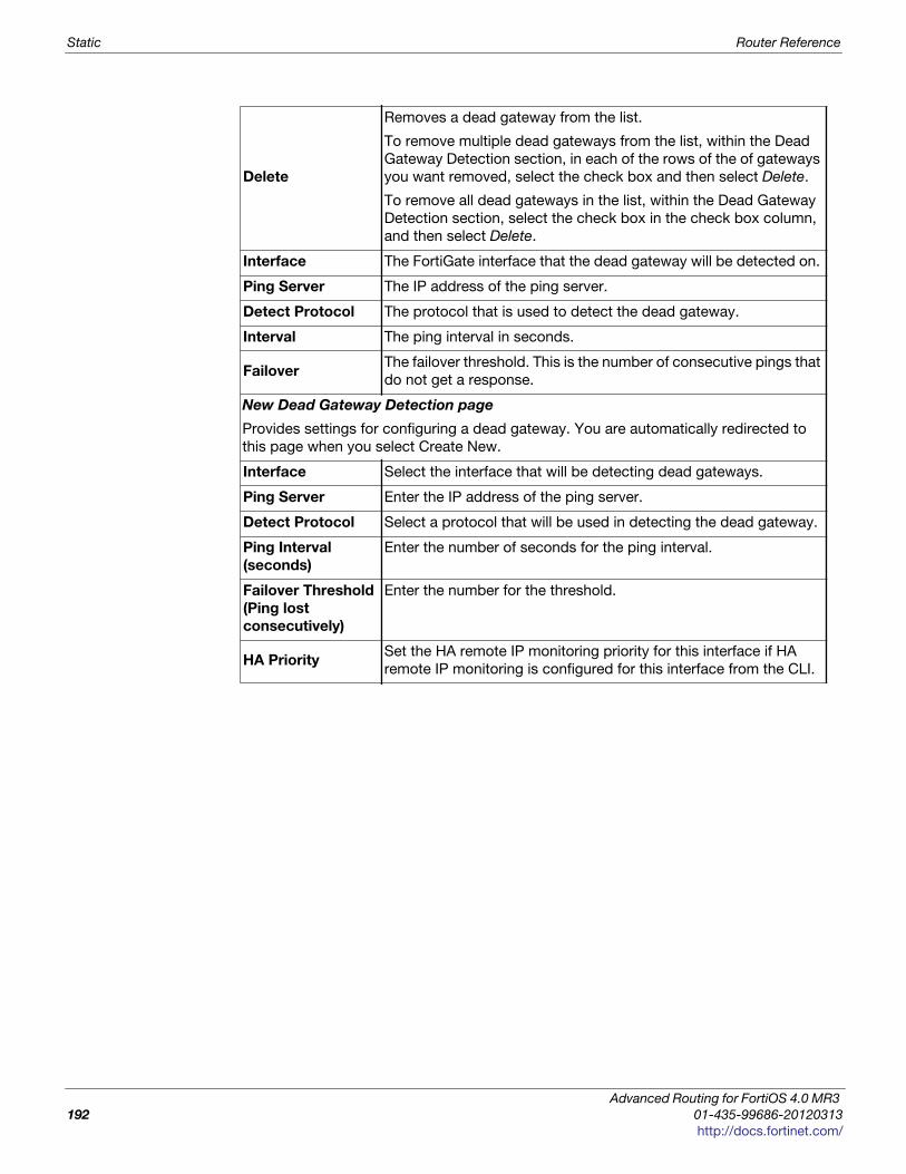
Static Router Reference
Delete
Removes a dead gateway from the list.
To remove multiple dead gateways from the list, within the Dead
Gateway Detection section, in each of the rows of the of gateways
you want removed, select the check box and then select Delete.
To remove all dead gateways in the list, within the Dead Gateway
Detection section, select the check box in the check box column,
and then select Delete.
Interface The FortiGate interface that the dead gateway will be detected on.
Ping Server The IP address of the ping server.
Detect Protocol The protocol that is used to detect the dead gateway.
Interval The ping interval in seconds.
FailoverThe failover threshold. This is the number of consecutive pings that
do not get a response.
New Dead Gateway Detection page
Provides settings for configuring a dead gateway. You are automatically redirected to
this page when you select Create New.
Interface Select the interface that will be detecting dead gateways.
Ping Server Enter the IP address of the ping server.
Detect Protocol Select a protocol that will be used in detecting the dead gateway.
Ping Interval
(seconds)
Enter the number of seconds for the ping interval.
Failover Threshold
(Ping lost
consecutively)
Enter the number for the threshold.
HA PrioritySet the HA remote IP monitoring priority for this interface if HA
remote IP monitoring is configured for this interface from the CLI.
Advanced Routing for FortiOS 4.0 MR3
192 01-435-99686-20120313
http://docs.fortinet.com/
Router Reference Dynamic
F
0
h
Dynamic
The Dynamic menu provides settings for configuring dynamic routing. Dynamic routing
protocols allow the unit to automatically share information about routes with neighboring
routers and learn about routes and networks advertised by them.
The unit supports these dynamic routing protocols:
• Routing Information Protocol (RIP)
• Open Shortest Path First (OSPF)
• Border Gateway Protocol (BGP).
This topic contains the following:
• RIP
• OSPF
• BGP
• Multicast
RIP
Routing Information Protocol (RIP) is a distance-vector routing protocol intended for
small, relatively homogeneous networks. The FortiGate implementation of RIP supports
RIP version 1 (see RFC 1058), RIP version 2 (see RFC 2453), as well as the IPv6 version
RIPng (see RFC 2080).
For detailed information about RIP, see “RIP background and concepts” on page 57.
A unit can operate as a Protocol Independent Multicast (PIM) version 2 router in the root
virtual domain. FortiGate units support PIM sparse mode and dense mode and can
service multicast servers or receivers on the network segment to which a FortiGate
interface is connected. PIM can use static routes, RIP, OSPF, or BGP to forward
multicast packets to their destinations.
ortiOS™ Handbook v3: Advanced Routing
1-435-99686-20120313 193
ttp://docs.fortinet.com/
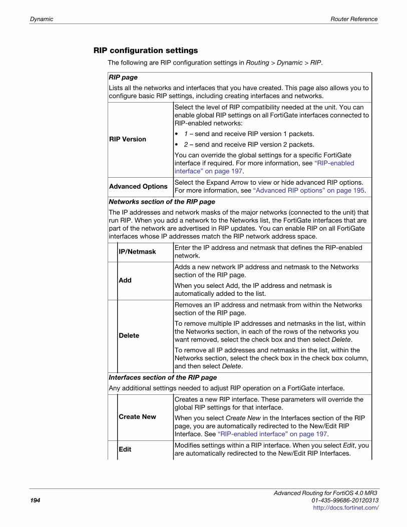
Dynamic Router Reference
RIP configuration settingsThe following are RIP configuration settings in Routing > Dynamic > RIP.
RIP page
Lists all the networks and interfaces that you have created. This page also allows you to
configure basic RIP settings, including creating interfaces and networks.
RIP Version
Select the level of RIP compatibility needed at the unit. You can
enable global RIP settings on all FortiGate interfaces connected to
RIP-enabled networks:
• 1 – send and receive RIP version 1 packets.
• 2 – send and receive RIP version 2 packets.
You can override the global settings for a specific FortiGate
interface if required. For more information, see “RIP-enabled
interface” on page 197.
Advanced OptionsSelect the Expand Arrow to view or hide advanced RIP options.
For more information, see “Advanced RIP options” on page 195.
Networks section of the RIP page
The IP addresses and network masks of the major networks (connected to the unit) that
run RIP. When you add a network to the Networks list, the FortiGate interfaces that are
part of the network are advertised in RIP updates. You can enable RIP on all FortiGate
interfaces whose IP addresses match the RIP network address space.
IP/NetmaskEnter the IP address and netmask that defines the RIP-enabled
network.
Add
Adds a new network IP address and netmask to the Networks
section of the RIP page.
When you select Add, the IP address and netmask is
automatically added to the list.
Delete
Removes an IP address and netmask from within the Networks
section of the RIP page.
To remove multiple IP addresses and netmasks in the list, within
the Networks section, in each of the rows of the networks you
want removed, select the check box and then select Delete.
To remove all IP addresses and netmasks in the list, within the
Networks section, select the check box in the check box column,
and then select Delete.
Interfaces section of the RIP page
Any additional settings needed to adjust RIP operation on a FortiGate interface.
Create New
Creates a new RIP interface. These parameters will override the
global RIP settings for that interface.
When you select Create New in the Interfaces section of the RIP
page, you are automatically redirected to the New/Edit RIP
Interface. See “RIP-enabled interface” on page 197.
EditModifies settings within a RIP interface. When you select Edit, you
are automatically redirected to the New/Edit RIP Interfaces.
Advanced Routing for FortiOS 4.0 MR3
194 01-435-99686-20120313
http://docs.fortinet.com/
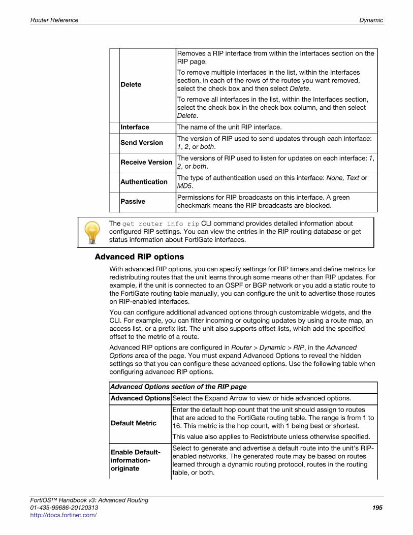
Router Reference Dynamic
F
0
h
Advanced RIP optionsWith advanced RIP options, you can specify settings for RIP timers and define metrics for
redistributing routes that the unit learns through some means other than RIP updates. For
example, if the unit is connected to an OSPF or BGP network or you add a static route to
the FortiGate routing table manually, you can configure the unit to advertise those routes
on RIP-enabled interfaces.
You can configure additional advanced options through customizable widgets, and the
CLI. For example, you can filter incoming or outgoing updates by using a route map, an
access list, or a prefix list. The unit also supports offset lists, which add the specified
offset to the metric of a route.
Advanced RIP options are configured in Router > Dynamic > RIP, in the Advanced
Options area of the page. You must expand Advanced Options to reveal the hidden
settings so that you can configure these advanced options. Use the following table when
configuring advanced RIP options.
Delete
Removes a RIP interface from within the Interfaces section on the
RIP page.
To remove multiple interfaces in the list, within the Interfaces
section, in each of the rows of the routes you want removed,
select the check box and then select Delete.
To remove all interfaces in the list, within the Interfaces section,
select the check box in the check box column, and then select
Delete.
Interface The name of the unit RIP interface.
Send VersionThe version of RIP used to send updates through each interface:
1, 2, or both.
Receive VersionThe versions of RIP used to listen for updates on each interface: 1,
2, or both.
AuthenticationThe type of authentication used on this interface: None, Text or
MD5.
PassivePermissions for RIP broadcasts on this interface. A green
checkmark means the RIP broadcasts are blocked.
The get router info rip CLI command provides detailed information about
configured RIP settings. You can view the entries in the RIP routing database or get
status information about FortiGate interfaces.
Advanced Options section of the RIP page
Advanced Options Select the Expand Arrow to view or hide advanced options.
Default Metric
Enter the default hop count that the unit should assign to routes
that are added to the FortiGate routing table. The range is from 1 to
16. This metric is the hop count, with 1 being best or shortest.
This value also applies to Redistribute unless otherwise specified.
Enable Default-
information-
originate
Select to generate and advertise a default route into the unit’s RIP-
enabled networks. The generated route may be based on routes
learned through a dynamic routing protocol, routes in the routing
table, or both.
ortiOS™ Handbook v3: Advanced Routing
1-435-99686-20120313 195
ttp://docs.fortinet.com/
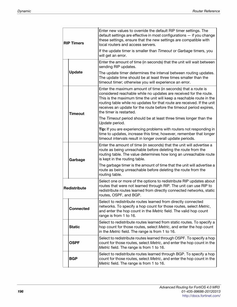
Dynamic Router Reference
RIP Timers
Enter new values to override the default RIP timer settings. The
default settings are effective in most configurations — if you change
these settings, ensure that the new settings are compatible with
local routers and access servers.
If the update timer is smaller than Timeout or Garbage timers, you
will get an error.
Update
Enter the amount of time (in seconds) that the unit will wait between
sending RIP updates.
The update timer determines the interval between routing updates.
The update time should be at least three times smaller than the
timeout timer; otherwise you will experience an error.
Timeout
Enter the maximum amount of time (in seconds) that a route is
considered reachable while no updates are received for the route.
This is the maximum time the unit will keep a reachable route in the
routing table while no updates for that route are received. If the unit
receives an update for the route before the timeout period expires,
the timer is restarted.
The Timeout period should be at least three times longer than the
Update period.
Tip: If you are experiencing problems with routers not responding in
time to updates, increase this time; however, remember that longer
timeout intervals result in longer overall update periods.
Garbage
Enter the amount of time (in seconds) that the unit will advertise a
route as being unreachable before deleting the route from the
routing table. The value determines how long an unreachable route
is kept in the routing table.
The garbage timer is the amount of time that the unit will advertise a
route as being unreachable before deleting the route from the
routing table.
Redistribute
Select one or more of the options to redistribute RIP updates about
routes that were not learned through RIP. The unit can use RIP to
redistribute routes learned from directly connected networks, static
routes, OSPF, and BGP.
Connected
Select to redistribute routes learned from directly connected
networks. To specify a hop count for those routes, select Metric,
and enter the hop count in the Metric field. The valid hop count
range is from 1 to 16.
Static
Select to redistribute routes learned from static routes. To specify a
hop count for those routes, select Metric, and enter the hop count
in the Metric field. The range is from 1 to 16.
OSPF
Select to redistribute routes learned through OSPF. To specify a hop
count for those routes, select Metric, and enter the hop count in the
Metric field. The range is from 1 to 16.
BGP
Select to redistribute routes learned through BGP. To specify a hop
count for those routes, select Metric, and enter the hop count in the
Metric field. The range is from 1 to 16.
Advanced Routing for FortiOS 4.0 MR3
196 01-435-99686-20120313
http://docs.fortinet.com/

Router Reference Dynamic
F
0
h
RIP-enabled interfaceYou can use RIP interface options to override the global RIP settings that apply to all unit
interfaces connected to RIP-enabled networks. For example, if you want to suppress RIP
advertising on an interface that is connected to a subnet of a RIP-enabled network, you
can set the interface to operate passively. Passive interfaces listen for RIP updates but do
not respond to RIP requests.
If RIP version 2 is enabled on the interface, you can optionally choose password
authentication to ensure that the unit authenticates a neighboring router before accepting
updates from that router. The unit and the neighboring router must both be configured
with the same password. Authentication guarantees the authenticity of the update
packet, not the confidentiality of the routing information in the packet.
RIP-enabled interface configuration settingsRIP-enabled interfaces are configured in Router > Dynamic > RIP. The following are RIP
interface configuration settings.
Additional options such as split-horizon and key-chains can be configured per interface
through the CLI.
New/Edit RIP Interface page
Provides settings for configuring a RIP Interface. When you select Create New in the
Interfaces section of the RIP page, you are automatically redirected to the New/Edit RIP
Interface page.
Interface
Select the name of the FortiGate interface to which these settings
apply. The interface must be connected to a RIP-enabled network.
The interface can be a virtual IPsec or GRE interface.
Send Version
Select to override the default RIP-compatibility setting for sending
updates through the interface. You can choose either RIP version 1,
2, or both RIP versions.
Receive Version
Select to override the default RIP-compatibility setting for receiving
updates through the interface. You can choose either RIP version 1, 2
or both RIP versions.
Authentication
Select an authentication method for RIP exchanges on the specified
interface:
• None — Disable authentication.
• Text — Select if the interface is connected to a network that runs
RIP version 2. Type a password (up to 35 characters) in the
Password field. The unit and the RIP updates router must both be
configured with the same password. The password is sent in clear
text over the network.
Password Enter the password for authentication.
Passive Interface
Select to suppress the advertising of unit routing information over the
specified interface. Clear the check box to allow the interface to
respond normally to RIP requests.
ortiOS™ Handbook v3: Advanced Routing
1-435-99686-20120313 197
ttp://docs.fortinet.com/
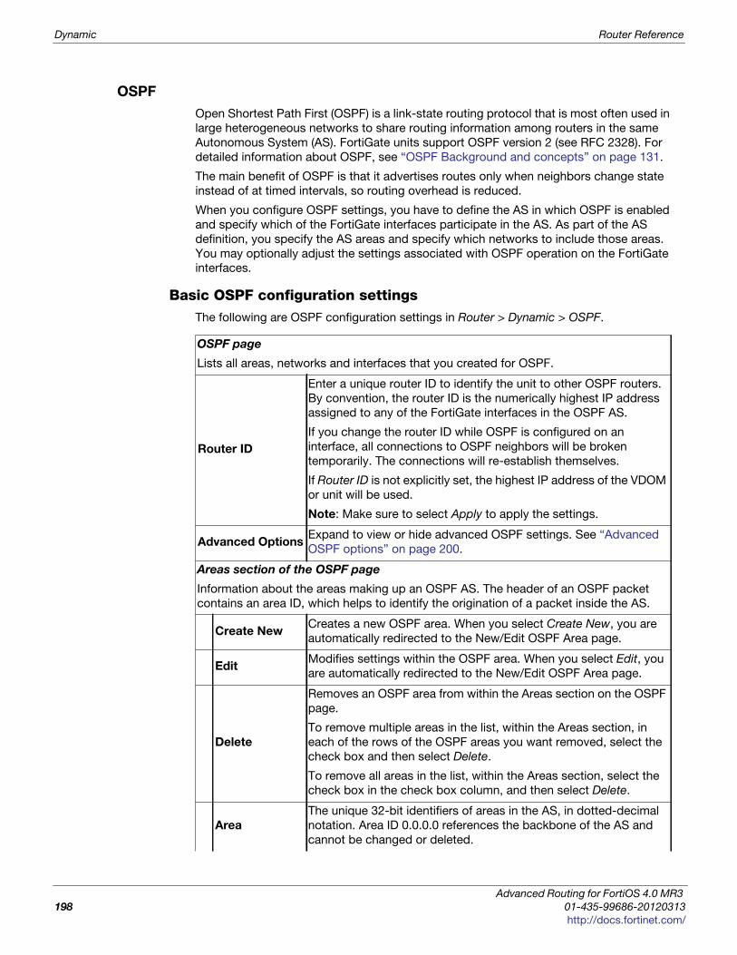
Dynamic Router Reference
OSPF
Open Shortest Path First (OSPF) is a link-state routing protocol that is most often used in
large heterogeneous networks to share routing information among routers in the same
Autonomous System (AS). FortiGate units support OSPF version 2 (see RFC 2328). For
detailed information about OSPF, see “OSPF Background and concepts” on page 131.
The main benefit of OSPF is that it advertises routes only when neighbors change state
instead of at timed intervals, so routing overhead is reduced.
When you configure OSPF settings, you have to define the AS in which OSPF is enabled
and specify which of the FortiGate interfaces participate in the AS. As part of the AS
definition, you specify the AS areas and specify which networks to include those areas.
You may optionally adjust the settings associated with OSPF operation on the FortiGate
interfaces.
Basic OSPF configuration settingsThe following are OSPF configuration settings in Router > Dynamic > OSPF.
OSPF page
Lists all areas, networks and interfaces that you created for OSPF.
Router ID
Enter a unique router ID to identify the unit to other OSPF routers.
By convention, the router ID is the numerically highest IP address
assigned to any of the FortiGate interfaces in the OSPF AS.
If you change the router ID while OSPF is configured on an
interface, all connections to OSPF neighbors will be broken
temporarily. The connections will re-establish themselves.
If Router ID is not explicitly set, the highest IP address of the VDOM
or unit will be used.
Note: Make sure to select Apply to apply the settings.
Advanced OptionsExpand to view or hide advanced OSPF settings. See “Advanced
OSPF options” on page 200.
Areas section of the OSPF page
Information about the areas making up an OSPF AS. The header of an OSPF packet
contains an area ID, which helps to identify the origination of a packet inside the AS.
Create NewCreates a new OSPF area. When you select Create New, you are
automatically redirected to the New/Edit OSPF Area page.
Edit Modifies settings within the OSPF area. When you select Edit, you
are automatically redirected to the New/Edit OSPF Area page.
Delete
Removes an OSPF area from within the Areas section on the OSPF
page.
To remove multiple areas in the list, within the Areas section, in
each of the rows of the OSPF areas you want removed, select the
check box and then select Delete.
To remove all areas in the list, within the Areas section, select the
check box in the check box column, and then select Delete.
Area
The unique 32-bit identifiers of areas in the AS, in dotted-decimal
notation. Area ID 0.0.0.0 references the backbone of the AS and
cannot be changed or deleted.
Advanced Routing for FortiOS 4.0 MR3
198 01-435-99686-20120313
http://docs.fortinet.com/
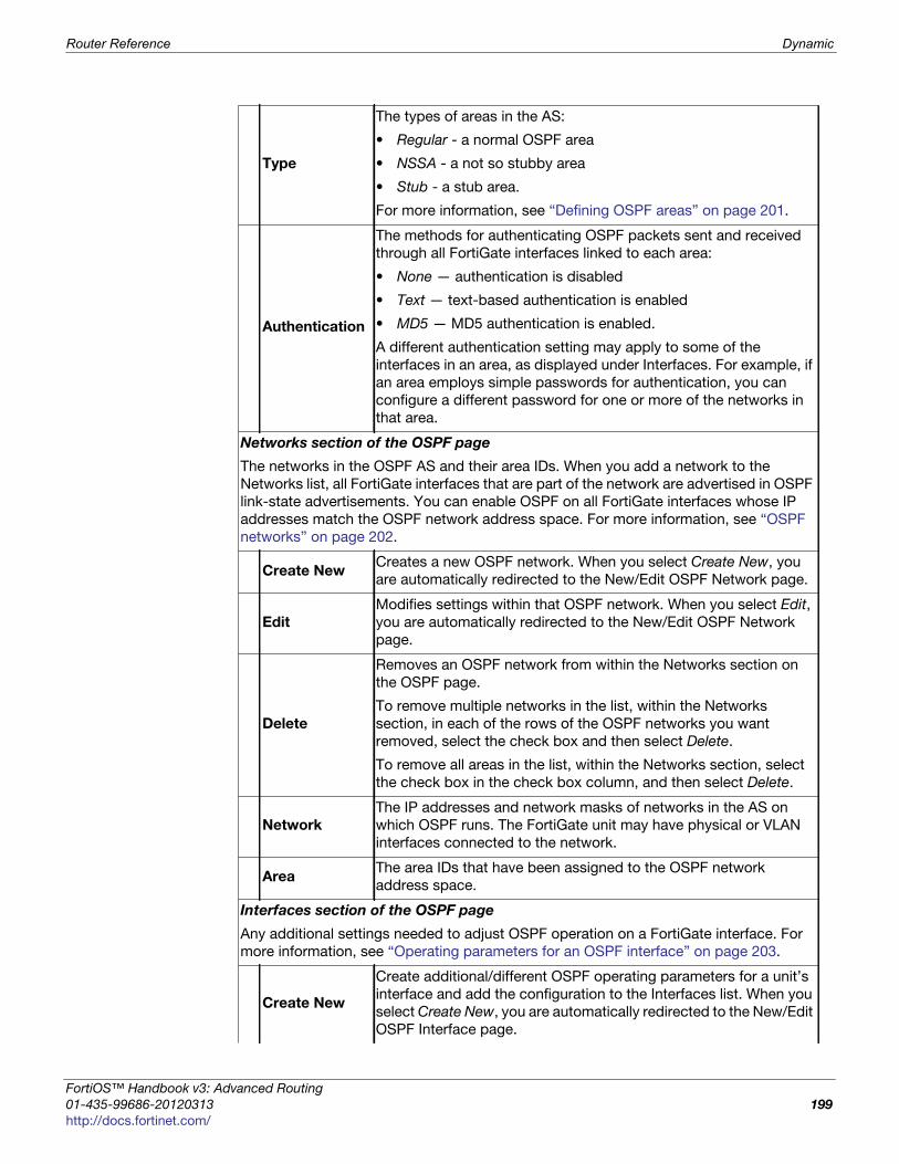
Router Reference Dynamic
F
0
h
Type
The types of areas in the AS:
• Regular - a normal OSPF area
• NSSA - a not so stubby area
• Stub - a stub area.
For more information, see “Defining OSPF areas” on page 201.
Authentication
The methods for authenticating OSPF packets sent and received
through all FortiGate interfaces linked to each area:
• None — authentication is disabled
• Text — text-based authentication is enabled
• MD5 — MD5 authentication is enabled.
A different authentication setting may apply to some of the
interfaces in an area, as displayed under Interfaces. For example, if
an area employs simple passwords for authentication, you can
configure a different password for one or more of the networks in
that area.
Networks section of the OSPF page
The networks in the OSPF AS and their area IDs. When you add a network to the
Networks list, all FortiGate interfaces that are part of the network are advertised in OSPF
link-state advertisements. You can enable OSPF on all FortiGate interfaces whose IP
addresses match the OSPF network address space. For more information, see “OSPF
networks” on page 202.
Create NewCreates a new OSPF network. When you select Create New, you
are automatically redirected to the New/Edit OSPF Network page.
Edit
Modifies settings within that OSPF network. When you select Edit,
you are automatically redirected to the New/Edit OSPF Network
page.
Delete
Removes an OSPF network from within the Networks section on
the OSPF page.
To remove multiple networks in the list, within the Networks
section, in each of the rows of the OSPF networks you want
removed, select the check box and then select Delete.
To remove all areas in the list, within the Networks section, select
the check box in the check box column, and then select Delete.
Network
The IP addresses and network masks of networks in the AS on
which OSPF runs. The FortiGate unit may have physical or VLAN
interfaces connected to the network.
AreaThe area IDs that have been assigned to the OSPF network
address space.
Interfaces section of the OSPF page
Any additional settings needed to adjust OSPF operation on a FortiGate interface. For
more information, see “Operating parameters for an OSPF interface” on page 203.
Create New
Create additional/different OSPF operating parameters for a unit’s
interface and add the configuration to the Interfaces list. When you
select Create New, you are automatically redirected to the New/Edit
OSPF Interface page.
ortiOS™ Handbook v3: Advanced Routing
1-435-99686-20120313 199
ttp://docs.fortinet.com/
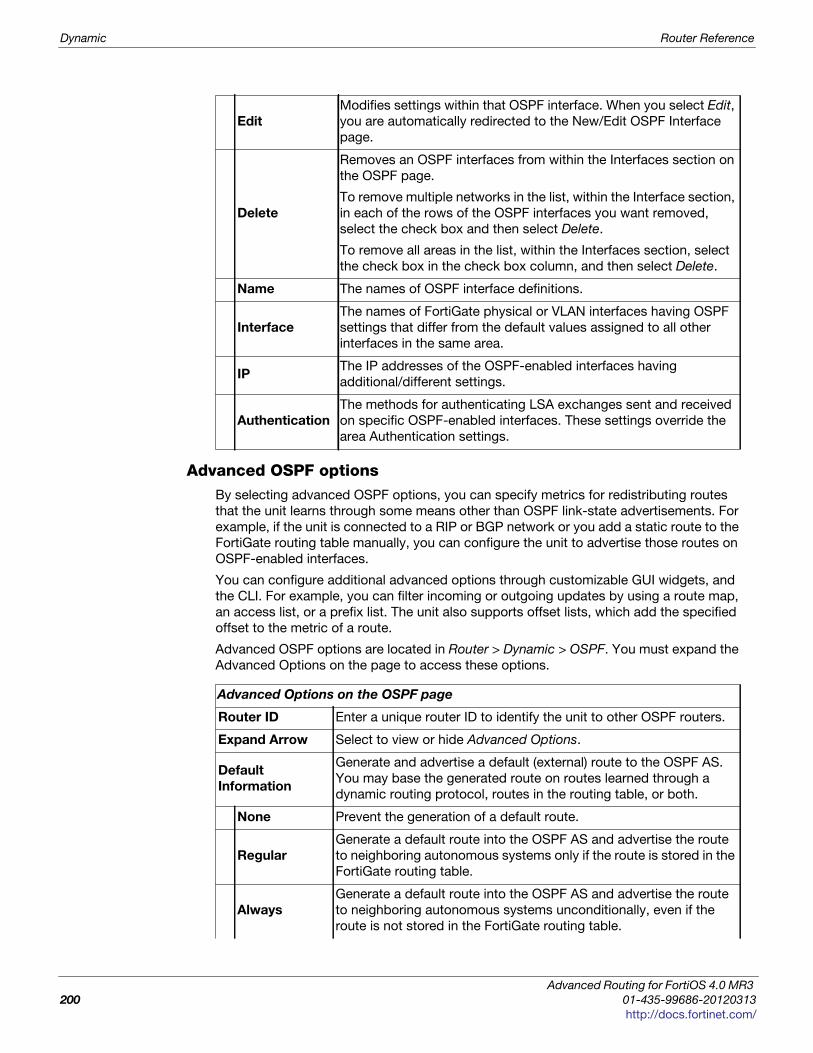
Dynamic Router Reference
Advanced OSPF optionsBy selecting advanced OSPF options, you can specify metrics for redistributing routes
that the unit learns through some means other than OSPF link-state advertisements. For
example, if the unit is connected to a RIP or BGP network or you add a static route to the
FortiGate routing table manually, you can configure the unit to advertise those routes on
OSPF-enabled interfaces.
You can configure additional advanced options through customizable GUI widgets, and
the CLI. For example, you can filter incoming or outgoing updates by using a route map,
an access list, or a prefix list. The unit also supports offset lists, which add the specified
offset to the metric of a route.
Advanced OSPF options are located in Router > Dynamic > OSPF. You must expand the
Advanced Options on the page to access these options.
Edit
Modifies settings within that OSPF interface. When you select Edit,
you are automatically redirected to the New/Edit OSPF Interface
page.
Delete
Removes an OSPF interfaces from within the Interfaces section on
the OSPF page.
To remove multiple networks in the list, within the Interface section,
in each of the rows of the OSPF interfaces you want removed,
select the check box and then select Delete.
To remove all areas in the list, within the Interfaces section, select
the check box in the check box column, and then select Delete.
Name The names of OSPF interface definitions.
Interface
The names of FortiGate physical or VLAN interfaces having OSPF
settings that differ from the default values assigned to all other
interfaces in the same area.
IPThe IP addresses of the OSPF-enabled interfaces having
additional/different settings.
Authentication
The methods for authenticating LSA exchanges sent and received
on specific OSPF-enabled interfaces. These settings override the
area Authentication settings.
Advanced Options on the OSPF page
Router ID Enter a unique router ID to identify the unit to other OSPF routers.
Expand Arrow Select to view or hide Advanced Options.
Default
Information
Generate and advertise a default (external) route to the OSPF AS.
You may base the generated route on routes learned through a
dynamic routing protocol, routes in the routing table, or both.
None Prevent the generation of a default route.
Regular
Generate a default route into the OSPF AS and advertise the route
to neighboring autonomous systems only if the route is stored in the
FortiGate routing table.
Always
Generate a default route into the OSPF AS and advertise the route
to neighboring autonomous systems unconditionally, even if the
route is not stored in the FortiGate routing table.
Advanced Routing for FortiOS 4.0 MR3
200 01-435-99686-20120313
http://docs.fortinet.com/
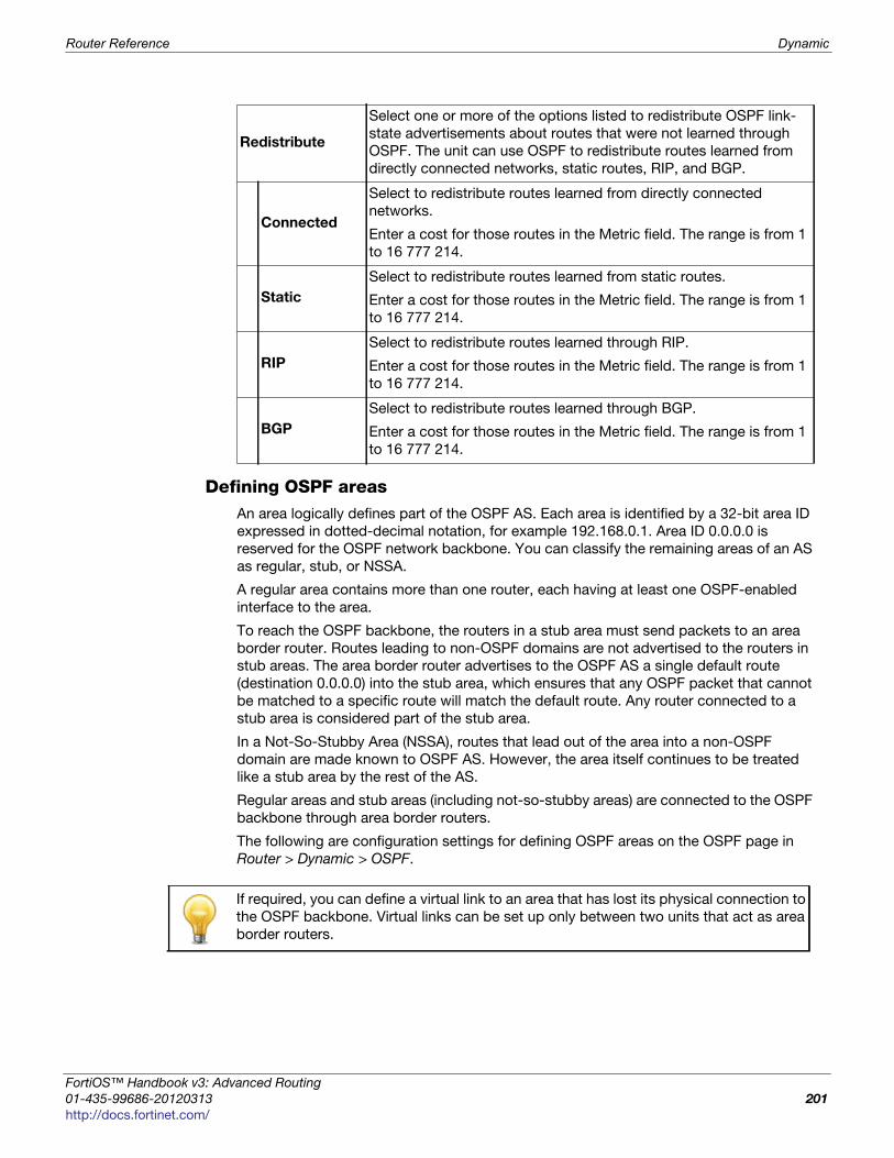
Router Reference Dynamic
F
0
h
Defining OSPF areasAn area logically defines part of the OSPF AS. Each area is identified by a 32-bit area ID
expressed in dotted-decimal notation, for example 192.168.0.1. Area ID 0.0.0.0 is
reserved for the OSPF network backbone. You can classify the remaining areas of an AS
as regular, stub, or NSSA.
A regular area contains more than one router, each having at least one OSPF-enabled
interface to the area.
To reach the OSPF backbone, the routers in a stub area must send packets to an area
border router. Routes leading to non-OSPF domains are not advertised to the routers in
stub areas. The area border router advertises to the OSPF AS a single default route
(destination 0.0.0.0) into the stub area, which ensures that any OSPF packet that cannot
be matched to a specific route will match the default route. Any router connected to a
stub area is considered part of the stub area.
In a Not-So-Stubby Area (NSSA), routes that lead out of the area into a non-OSPF
domain are made known to OSPF AS. However, the area itself continues to be treated
like a stub area by the rest of the AS.
Regular areas and stub areas (including not-so-stubby areas) are connected to the OSPF
backbone through area border routers.
The following are configuration settings for defining OSPF areas on the OSPF page in
Router > Dynamic > OSPF.
Redistribute
Select one or more of the options listed to redistribute OSPF link-
state advertisements about routes that were not learned through
OSPF. The unit can use OSPF to redistribute routes learned from
directly connected networks, static routes, RIP, and BGP.
Connected
Select to redistribute routes learned from directly connected
networks.
Enter a cost for those routes in the Metric field. The range is from 1
to 16 777 214.
Static
Select to redistribute routes learned from static routes.
Enter a cost for those routes in the Metric field. The range is from 1
to 16 777 214.
RIP
Select to redistribute routes learned through RIP.
Enter a cost for those routes in the Metric field. The range is from 1
to 16 777 214.
BGP
Select to redistribute routes learned through BGP.
Enter a cost for those routes in the Metric field. The range is from 1
to 16 777 214.
If required, you can define a virtual link to an area that has lost its physical connection to
the OSPF backbone. Virtual links can be set up only between two units that act as area
border routers.
ortiOS™ Handbook v3: Advanced Routing
1-435-99686-20120313 201
ttp://docs.fortinet.com/
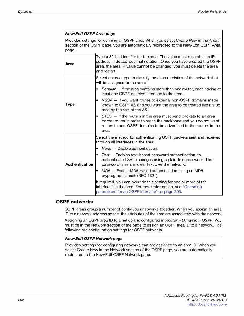
Dynamic Router Reference
OSPF networksOSPF areas group a number of contiguous networks together. When you assign an area
ID to a network address space, the attributes of the area are associated with the network.
Assigning an OSPF area ID to a network is configured in Router > Dynamic > OSPF. You
must be in the Network section of the page to assign an OSPF area ID to a network. The
following are configuration settings for OSPF networks.
New/Edit OSPF Area page
Provides settings for defining an OSPF area. When you select Create New in the Areas
section of the OSPF page, you are automatically redirected to the New/Edit OSPF Area
page.
Area
Type a 32-bit identifier for the area. The value must resemble an IP
address in dotted-decimal notation. Once you have created the OSPF
area, the area IP value cannot be changed; you must delete the area
and restart.
Type
Select an area type to classify the characteristics of the network that
will be assigned to the area:
• Regular — If the area contains more than one router, each having at
least one OSPF-enabled interface to the area.
• NSSA — If you want routes to external non-OSPF domains made
known to OSPF AS and you want the area to be treated like a stub
area by the rest of the AS.
• STUB — If the routers in the area must send packets to an area
border router in order to reach the backbone and you do not want
routes to non-OSPF domains to be advertised to the routers in the
area.
Authentication
Select the method for authenticating OSPF packets sent and received
through all interfaces in the area:
• None — Disable authentication.
• Text — Enables text-based password authentication. to
authenticate LSA exchanges using a plain-text password. The
password is sent in clear text over the network.
• MD5 — Enable MD5-based authentication using an MD5
cryptographic hash (RFC 1321).
If required, you can override this setting for one or more of the
interfaces in the area. For more information, see “Operating
parameters for an OSPF interface” on page 203.
New/Edit OSPF Network page
Provides settings for configuring networks that are assigned to an area ID. When you
select Create New in the Network section of the OSPF page, you are automatically
redirected to the New/Edit OSPF Network page.
Advanced Routing for FortiOS 4.0 MR3
202 01-435-99686-20120313
http://docs.fortinet.com/
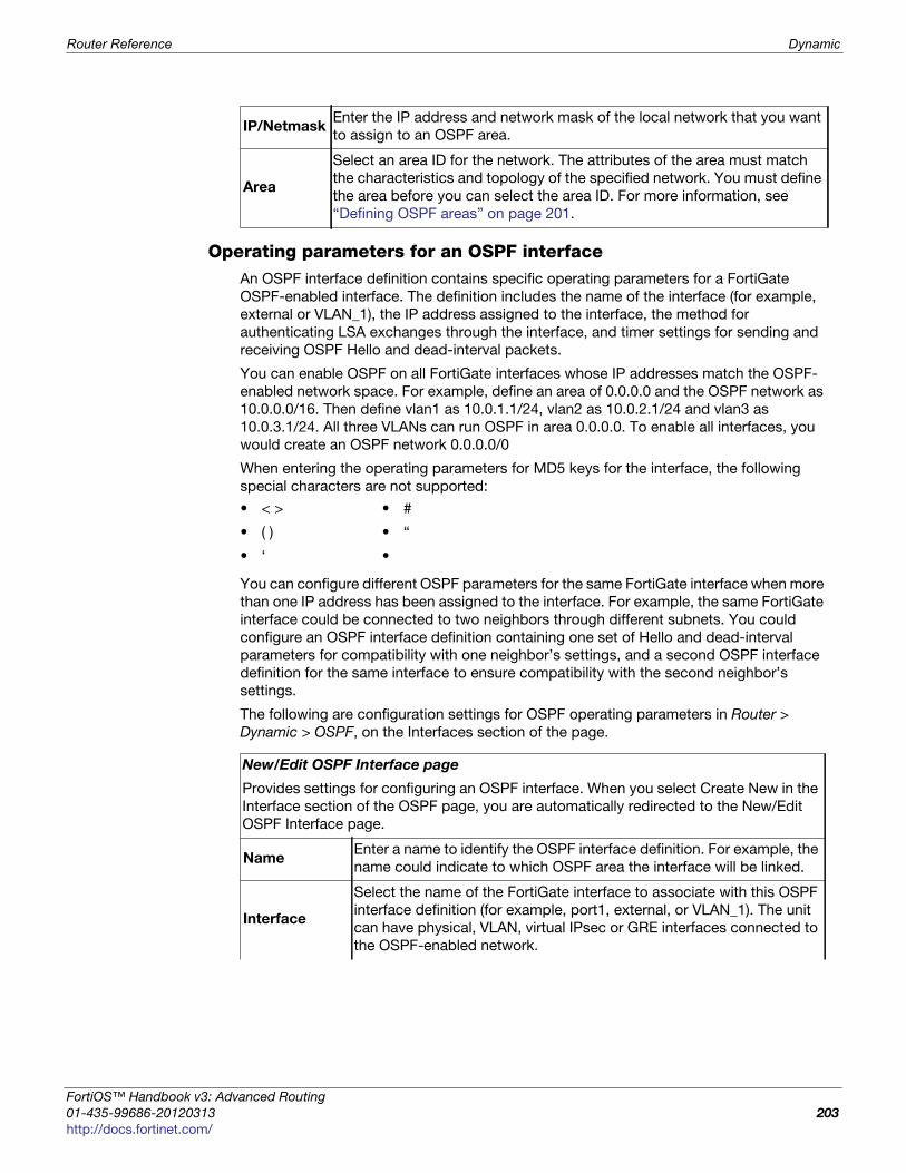
Router Reference Dynamic
F
0
h
Operating parameters for an OSPF interfaceAn OSPF interface definition contains specific operating parameters for a FortiGate
OSPF-enabled interface. The definition includes the name of the interface (for example,
external or VLAN_1), the IP address assigned to the interface, the method for
authenticating LSA exchanges through the interface, and timer settings for sending and
receiving OSPF Hello and dead-interval packets.
You can enable OSPF on all FortiGate interfaces whose IP addresses match the OSPF-
enabled network space. For example, define an area of 0.0.0.0 and the OSPF network as
10.0.0.0/16. Then define vlan1 as 10.0.1.1/24, vlan2 as 10.0.2.1/24 and vlan3 as
10.0.3.1/24. All three VLANs can run OSPF in area 0.0.0.0. To enable all interfaces, you
would create an OSPF network 0.0.0.0/0
When entering the operating parameters for MD5 keys for the interface, the following
special characters are not supported:
You can configure different OSPF parameters for the same FortiGate interface when more
than one IP address has been assigned to the interface. For example, the same FortiGate
interface could be connected to two neighbors through different subnets. You could
configure an OSPF interface definition containing one set of Hello and dead-interval
parameters for compatibility with one neighbor’s settings, and a second OSPF interface
definition for the same interface to ensure compatibility with the second neighbor’s
settings.
The following are configuration settings for OSPF operating parameters in Router >
Dynamic > OSPF, on the Interfaces section of the page.
IP/NetmaskEnter the IP address and network mask of the local network that you want
to assign to an OSPF area.
Area
Select an area ID for the network. The attributes of the area must match
the characteristics and topology of the specified network. You must define
the area before you can select the area ID. For more information, see
“Defining OSPF areas” on page 201.
• < > • #
• ( ) • “
• ‘ •
New/Edit OSPF Interface page
Provides settings for configuring an OSPF interface. When you select Create New in the
Interface section of the OSPF page, you are automatically redirected to the New/Edit
OSPF Interface page.
NameEnter a name to identify the OSPF interface definition. For example, the
name could indicate to which OSPF area the interface will be linked.
Interface
Select the name of the FortiGate interface to associate with this OSPF
interface definition (for example, port1, external, or VLAN_1). The unit
can have physical, VLAN, virtual IPsec or GRE interfaces connected to
the OSPF-enabled network.
ortiOS™ Handbook v3: Advanced Routing
1-435-99686-20120313 203
ttp://docs.fortinet.com/
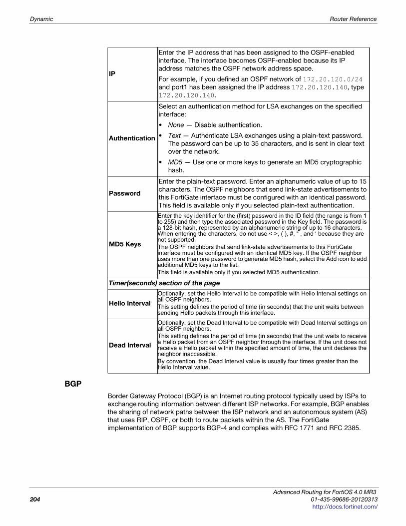
Dynamic Router Reference
BGP
Border Gateway Protocol (BGP) is an Internet routing protocol typically used by ISPs to
exchange routing information between different ISP networks. For example, BGP enables
the sharing of network paths between the ISP network and an autonomous system (AS)
that uses RIP, OSPF, or both to route packets within the AS. The FortiGate
implementation of BGP supports BGP-4 and complies with RFC 1771 and RFC 2385.
IP
Enter the IP address that has been assigned to the OSPF-enabled
interface. The interface becomes OSPF-enabled because its IP
address matches the OSPF network address space.
For example, if you defined an OSPF network of 172.20.120.0/24
and port1 has been assigned the IP address 172.20.120.140, type
172.20.120.140.
Authentication
Select an authentication method for LSA exchanges on the specified
interface:
• None — Disable authentication.
• Text — Authenticate LSA exchanges using a plain-text password.
The password can be up to 35 characters, and is sent in clear text
over the network.
• MD5 — Use one or more keys to generate an MD5 cryptographic
hash.
Password
Enter the plain-text password. Enter an alphanumeric value of up to 15
characters. The OSPF neighbors that send link-state advertisements to
this FortiGate interface must be configured with an identical password.
This field is available only if you selected plain-text authentication.
MD5 Keys
Enter the key identifier for the (first) password in the ID field (the range is from 1 to 255) and then type the associated password in the Key field. The password is a 128-bit hash, represented by an alphanumeric string of up to 16 characters. When entering the characters, do not use < >, ( ), #, “ , and ‘ because they are not supported. The OSPF neighbors that send link-state advertisements to this FortiGate interface must be configured with an identical MD5 key. If the OSPF neighbor uses more than one password to generate MD5 hash, select the Add icon to add additional MD5 keys to the list. This field is available only if you selected MD5 authentication.
Timer(seconds) section of the page
Hello Interval
Optionally, set the Hello Interval to be compatible with Hello Interval settings on all OSPF neighbors. This setting defines the period of time (in seconds) that the unit waits between sending Hello packets through this interface.
Dead Interval
Optionally, set the Dead Interval to be compatible with Dead Interval settings on all OSPF neighbors. This setting defines the period of time (in seconds) that the unit waits to receive a Hello packet from an OSPF neighbor through the interface. If the unit does not receive a Hello packet within the specified amount of time, the unit declares the neighbor inaccessible.By convention, the Dead Interval value is usually four times greater than the Hello Interval value.
Advanced Routing for FortiOS 4.0 MR3
204 01-435-99686-20120313
http://docs.fortinet.com/
Router Reference Dynamic
F
0
h
For more information, see “BGP background and concepts” on page 93.
When you configure BGP settings, you need to specify the AS to which the unit belongs
and enter a router ID to identify this unit to other BGP routers. You must also identify the
unit’s BGP neighbors and specify which of the networks local to the unit should be
advertised to BGP neighbors.
You can configure graceful restarting and other advanced settings only through CLI
commands.
ortiOS™ Handbook v3: Advanced Routing
1-435-99686-20120313 205
ttp://docs.fortinet.com/
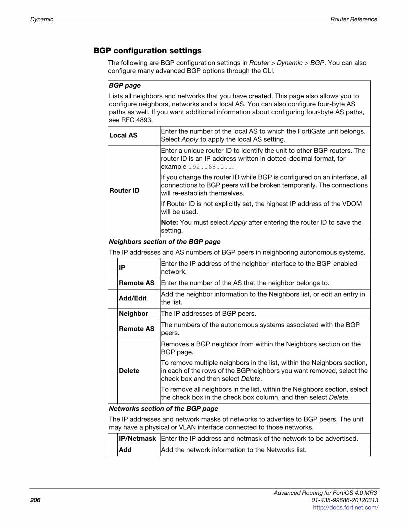
Dynamic Router Reference
BGP configuration settingsThe following are BGP configuration settings in Router > Dynamic > BGP. You can also
configure many advanced BGP options through the CLI.
BGP page
Lists all neighbors and networks that you have created. This page also allows you to
configure neighbors, networks and a local AS. You can also configure four-byte AS
paths as well. If you want additional information about configuring four-byte AS paths,
see RFC 4893.
Local ASEnter the number of the local AS to which the FortiGate unit belongs.
Select Apply to apply the local AS setting.
Router ID
Enter a unique router ID to identify the unit to other BGP routers. The
router ID is an IP address written in dotted-decimal format, for
example 192.168.0.1.
If you change the router ID while BGP is configured on an interface, all
connections to BGP peers will be broken temporarily. The connections
will re-establish themselves.
If Router ID is not explicitly set, the highest IP address of the VDOM
will be used.
Note: You must select Apply after entering the router ID to save the
setting.
Neighbors section of the BGP page
The IP addresses and AS numbers of BGP peers in neighboring autonomous systems.
IPEnter the IP address of the neighbor interface to the BGP-enabled
network.
Remote AS Enter the number of the AS that the neighbor belongs to.
Add/EditAdd the neighbor information to the Neighbors list, or edit an entry in
the list.
Neighbor The IP addresses of BGP peers.
Remote ASThe numbers of the autonomous systems associated with the BGP
peers.
Delete
Removes a BGP neighbor from within the Neighbors section on the
BGP page.
To remove multiple neighbors in the list, within the Neighbors section,
in each of the rows of the BGPneighbors you want removed, select the
check box and then select Delete.
To remove all neighbors in the list, within the Neighbors section, select
the check box in the check box column, and then select Delete.
Networks section of the BGP page
The IP addresses and network masks of networks to advertise to BGP peers. The unit
may have a physical or VLAN interface connected to those networks.
IP/Netmask Enter the IP address and netmask of the network to be advertised.
Add Add the network information to the Networks list.
Advanced Routing for FortiOS 4.0 MR3
206 01-435-99686-20120313
http://docs.fortinet.com/
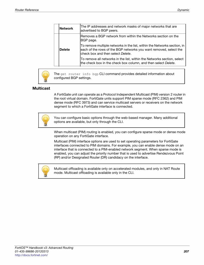
Router Reference Dynamic
F
0
h
Multicast
A FortiGate unit can operate as a Protocol Independent Multicast (PIM) version 2 router in
the root virtual domain. FortiGate units support PIM sparse mode (RFC 2362) and PIM
dense mode (RFC 3973) and can service multicast servers or receivers on the network
segment to which a FortiGate interface is connected.
When multicast (PIM) routing is enabled, you can configure sparse mode or dense mode
operation on any FortiGate interface.
Multicast (PIM) interface options are used to set operating parameters for FortiGate
interfaces connected to PIM domains. For example, you can enable dense mode on an
interface that is connected to a PIM-enabled network segment. When sparse mode is
enabled, you can adjust the priority number that is used to advertise Rendezvous Point
(RP) and/or Designated Router (DR) candidacy on the interface.
NetworkThe IP addresses and network masks of major networks that are
advertised to BGP peers.
Delete
Removes a BGP network from within the Networks section on the
BGP page.
To remove multiple networks in the list, within the Networks section, in
each of the rows of the BGP networks you want removed, select the
check box and then select Delete.
To remove all networks in the list, within the Networks section, select
the check box in the check box column, and then select Delete.
The get router info bgp CLI command provides detailed information about
configured BGP settings.
You can configure basic options through the web-based manager. Many additional
options are available, but only through the CLI.
Multicast offloading is available only on accelerated modules, and only in NAT Route
mode. Multicast offloading is available only in the CLI.
ortiOS™ Handbook v3: Advanced Routing
1-435-99686-20120313 207
ttp://docs.fortinet.com/
Dynamic Router Reference
Sparse modeInitially, all candidate BSRs in a PIM domain exchange bootstrap messages to select one
BSR to which each RP sends the multicast address or addresses of the multicast
group(s) that it can service. The selected BSR chooses one RP per multicast group and
makes this information available to all of the PIM routers in the domain through bootstrap
messages. PIM routers use the information to build packet distribution trees, which map
each multicast group to a specific RP. Packet distribution trees may also contain
information about the sources and receivers associated with particular multicast groups.
An RP represents the root of a non-source-specific distribution tree to a multicast group.
By joining and pruning the information contained in distribution trees, a single stream of
multicast packets (for example, a video feed) originating from the source can be
forwarded to a certain RP to reach a multicast destination.
Each PIM router maintains a Multicast Routing Information Base (MRIB) that determines
to which neighboring PIM router join and prune messages are sent. An MRIB contains
reverse-path information that reveals the path of a multicast packet from its source to the
PIM router that maintains the MRIB.
To send multicast traffic, a server application sends IP traffic to a multicast group
address. The locally elected DR registers the sender with the RP that is associated with
the target multicast group. The RP uses its MRIB to forward a single stream of IP packets
from the source to the members of the multicast group. The IP packets are replicated
only when necessary to distribute the data to branches of the RP’s distribution tree.
To receive multicast traffic, a client application can use Internet Group Management
Protocol (IGMP) version 1 (RFC 1112), 2 (RFC 2236), or 3 (RFC 3376) control messages to
request the traffic for a particular multicast group. The locally elected DR receives the
request and adds the host to the multicast group that is associated with the connected
network segment by sending a join message towards the RP for the group. Afterward, the
DR queries the hosts on the connected network segment continually to determine
whether the hosts are active. When the DR no longer receives confirmation that at least
one member of the multicast group is still active, the DR sends a prune message towards
the RP for the group.
Dense modeThe packet organization used in sparse mode is also used in dense mode. When a
multicast source begins to send IP traffic and dense mode is enabled, the closest PIM
router registers the IP traffic from the multicast source (S) and forwards multicast packets
to the multicast group address (G). All PIM routers initially broadcast the multicast
packets throughout the PIM domain to ensure that all receivers that have requested
traffic for multicast group address G can access the information if needed.
When a FortiGate interface is configured as a multicast interface, sparse mode is
enabled on it by default to ensure that distribution trees are not built unless at least one
downstream receiver requests multicast traffic from a specific source. If the sources of
multicast traffic and their receivers are close to each other and the PIM domain contains
a dense population of active receivers, you may choose to enable dense mode
throughout the PIM domain instead.
Advanced Routing for FortiOS 4.0 MR3
208 01-435-99686-20120313
http://docs.fortinet.com/
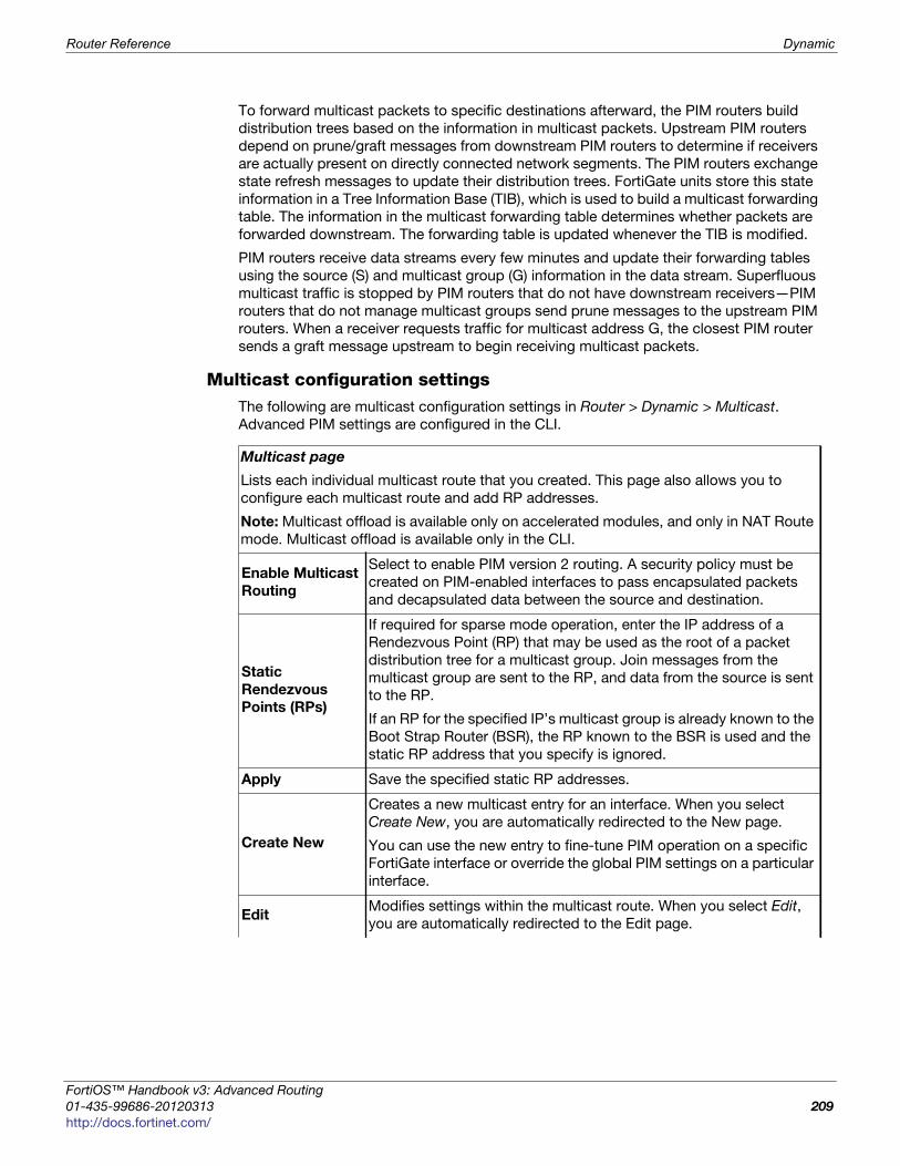
Router Reference Dynamic
F
0
h
To forward multicast packets to specific destinations afterward, the PIM routers build
distribution trees based on the information in multicast packets. Upstream PIM routers
depend on prune/graft messages from downstream PIM routers to determine if receivers
are actually present on directly connected network segments. The PIM routers exchange
state refresh messages to update their distribution trees. FortiGate units store this state
information in a Tree Information Base (TIB), which is used to build a multicast forwarding
table. The information in the multicast forwarding table determines whether packets are
forwarded downstream. The forwarding table is updated whenever the TIB is modified.
PIM routers receive data streams every few minutes and update their forwarding tables
using the source (S) and multicast group (G) information in the data stream. Superfluous
multicast traffic is stopped by PIM routers that do not have downstream receivers—PIM
routers that do not manage multicast groups send prune messages to the upstream PIM
routers. When a receiver requests traffic for multicast address G, the closest PIM router
sends a graft message upstream to begin receiving multicast packets.
Multicast configuration settingsThe following are multicast configuration settings in Router > Dynamic > Multicast.
Advanced PIM settings are configured in the CLI.
Multicast page
Lists each individual multicast route that you created. This page also allows you to
configure each multicast route and add RP addresses.
Note: Multicast offload is available only on accelerated modules, and only in NAT Route
mode. Multicast offload is available only in the CLI.
Enable Multicast
Routing
Select to enable PIM version 2 routing. A security policy must be
created on PIM-enabled interfaces to pass encapsulated packets
and decapsulated data between the source and destination.
Static
Rendezvous
Points (RPs)
If required for sparse mode operation, enter the IP address of a
Rendezvous Point (RP) that may be used as the root of a packet
distribution tree for a multicast group. Join messages from the
multicast group are sent to the RP, and data from the source is sent
to the RP.
If an RP for the specified IP’s multicast group is already known to the
Boot Strap Router (BSR), the RP known to the BSR is used and the
static RP address that you specify is ignored.
Apply Save the specified static RP addresses.
Create New
Creates a new multicast entry for an interface. When you select
Create New, you are automatically redirected to the New page.
You can use the new entry to fine-tune PIM operation on a specific
FortiGate interface or override the global PIM settings on a particular
interface.
Edit Modifies settings within the multicast route. When you select Edit,
you are automatically redirected to the Edit page.
ortiOS™ Handbook v3: Advanced Routing
1-435-99686-20120313 209
ttp://docs.fortinet.com/
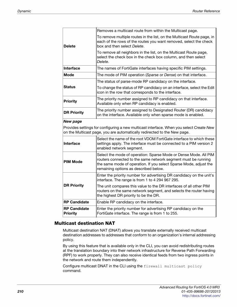
Dynamic Router Reference
Multicast destination NATMulticast destination NAT (DNAT) allows you translate externally received multicast
destination addresses to addresses that conform to an organization's internal addressing
policy.
By using this feature that is available only in the CLI, you can avoid redistributing routes
at the translation boundary into their network infrastructure for Reverse Path Forwarding
(RPF) to work properly. They can also receive identical feeds from two ingress points in
the network and route them independently.
Configure multicast DNAT in the CLI using the firewall multicast policy
command.
Delete
Removes a multicast route from within the Multicast page.
To remove multiple routes in the list, on the Multicast Route page, in
each of the rows of the routes you want removed, select the check
box and then select Delete.
To remove all neighbors in the list, on the Multicast Route page,
select the check box in the check box column, and then select
Delete.
Interface The names of FortiGate interfaces having specific PIM settings.
Mode The mode of PIM operation (Sparse or Dense) on that interface.
Status
The status of parse-mode RP candidacy on the interface.
To change the status of RP candidacy on an interface, select the Edit
icon in the row that corresponds to the interface.
PriorityThe priority number assigned to RP candidacy on that interface.
Available only when RP candidacy is enabled.
DR PriorityThe priority number assigned to Designated Router (DR) candidacy
on the interface. Available only when sparse mode is enabled.
New page
Provides settings for configuring a new multicast interface. When you select Create New
on the Multicast page, you are automatically redirected to the New page.
Interface
Select the name of the root VDOM FortiGate interface to which these
settings apply. The interface must be connected to a PIM version 2
enabled network segment.
PIM Mode
Select the mode of operation: Sparse Mode or Dense Mode. All PIM
routers connected to the same network segment must be running
the same mode of operation. If you select Sparse Mode, adjust the
remaining options as described below.
DR Priority
Enter the priority number for advertising DR candidacy on the unit’s
interface. The range is from 1 to 4 294 967 295.
The unit compares this value to the DR interfaces of all other PIM
routers on the same network segment, and selects the router having
the highest DR priority to be the DR.
RP Candidate Enable RP candidacy on the interface.
RP Candidate
Priority
Enter the priority number for advertising RP candidacy on the
FortiGate interface. The range is from 1 to 255.
Advanced Routing for FortiOS 4.0 MR3
210 01-435-99686-20120313
http://docs.fortinet.com/
Router Reference Dynamic
F
0
h
Bi-directional Forwarding Detection (BFD)
The Bi-directional Forwarding Detection (BFD) protocol is designed to deal with dynamic
routing protocols' lack of a fine granularity for detecting device failures on the network
and re-routing around those failures. BFD can more quickly react to these failures, since it
detects them on a millisecond timer, where other dynamic routing protocols can only
detect them on a second timer.
Your unit supports BFD as part of OSPF and BGP dynamic networking. BFD is
configured only in the CLI.
Configuring BFDBFD is intended for networks that use BGP or OSPF routing protocols. This generally
excludes smaller networks.
BFD configuration on your unit is very flexible. You can enable BFD for the whole unit,
and turn it off for one or two interfaces. Alternatively you can specifically enable BFD for
each neighbor router, or interface. Which method you choose will be determined by the
amount of configuring required for your network
The timeout period determines how long the unit waits before labeling a connection as
down. The length of the timeout period is important—if it is too short connections will be
labeled down prematurely, and if it is too long time will be wasted waiting for a reply from
a connection that is down. There is no easy number, as it varies for each network and
unit. High end models will respond very quickly unless loaded down with traffic. Also the
size of the network will slow down the response time—packets need to make more hops
than on a smaller network. Those two factors (CPU load and network traversal time)
affect how long the timeout you select should be. With too short a timeout period, BFD
will not connect to the network device but it will keep trying. This state generates
unnecessary network traffic, and leaves the device unmonitored. If this happens, you
should try setting a longer timeout period to allow BFD more time to discover the device
on the network.
For this example, BFD is enabled on the unit using the default values. This means that
once a connection is established, your unit will wait for up to 150 milliseconds for a reply
from a BFD router before declaring that router down and rerouting traffic—a 50
millisecond minimum transmit interval multiplied by a detection multiplier of 3. The port
that BFD traffic originates from will be checked for security purposes as indicated by
disabling bfd-dont-enforce-src-port.
config system settingsset bfd enableset bfd-desired-min-tx 50set bfd-required-min-rx 50set bfd-detect-mult 3set bfd-dont-enforce-src-port disable
end
The minimum receive interval (bfd-required-min-rx) and the detection multiplier
(bfd-detect-mult) combine to determine how long a period your unit will wait for a
reply before declaring the neighbor down. The correct value for your situation will vary
based on the size of your network and the speed of your unit’s CPU. The numbers used
in this example may not work for your network.
ortiOS™ Handbook v3: Advanced Routing
1-435-99686-20120313 211
ttp://docs.fortinet.com/
Dynamic Router Reference
Disabling BFD for a specific interfaceThe previous example enables BFD for your entire unit. If an interface is not connected to
any BFD enabled routers, you can reduce network traffic by disabling BFD for that
interface. For this example, BFD is disabled for the internal interface using CLI
commands.
config system interfaceedit <interface>set bfd disable
end
Access ListAccess lists are filters used by the unit’s routing processes to limit access to the network
based on IP addresses. For an access list to take effect, it must be called by a unit
routing process (for example, a process that supports RIP or OSPF). The offset list is part
of the RIP and OSPF routing protocols. Access lists are configured only in the CLI.
For more information about access lists, see (for RIP) “Access Lists” on page 61 or (for
OSPF) “Access Lists” on page 137.
Advanced Routing for FortiOS 4.0 MR3
212 01-435-99686-20120313
http://docs.fortinet.com/
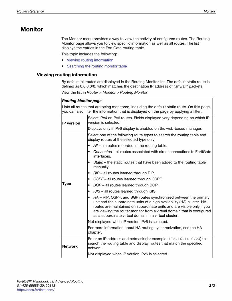
Router Reference Monitor
F
0
h
Monitor
The Monitor menu provides a way to view the activity of configured routes. The Routing
Monitor page allows you to view specific information as well as all routes. The list
displays the entries in the FortiGate routing table.
This topic includes the following:
• Viewing routing information
• Searching the routing monitor table
Viewing routing information
By default, all routes are displayed in the Routing Monitor list. The default static route is
defined as 0.0.0.0/0, which matches the destination IP address of “any/all” packets.
View the list in Router > Monitor > Routing Monitor.
Routing Monitor page
Lists all routes that are being monitored, including the default static route. On this page,
you can also filter the information that is displayed on the page by applying a filter.
IP version
Select IPv4 or IPv6 routes. Fields displayed vary depending on which IP
version is selected.
Displays only if IPv6 display is enabled on the web-based manager.
Type
Select one of the following route types to search the routing table and
display routes of the selected type only:
• All – all routes recorded in the routing table.
• Connected – all routes associated with direct connections to FortiGate
interfaces.
• Static – the static routes that have been added to the routing table
manually.
• RIP – all routes learned through RIP.
• OSPF – all routes learned through OSPF.
• BGP – all routes learned through BGP.
• ISIS – all routes learned through ISIS.
• HA – RIP, OSPF, and BGP routes synchronized between the primary
unit and the subordinate units of a high availability (HA) cluster. HA
routes are maintained on subordinate units and are visible only if you
are viewing the router monitor from a virtual domain that is configured
as a subordinate virtual domain in a virtual cluster.
Not displayed when IP version IPv6 is selected.
For more information about HA routing synchronization, see the HA
chapter.
Network
Enter an IP address and netmask (for example, 172.16.14.0/24) to
search the routing table and display routes that match the specified
network.
Not displayed when IP version IPv6 is selected.
ortiOS™ Handbook v3: Advanced Routing
1-435-99686-20120313 213
ttp://docs.fortinet.com/

Monitor Router Reference
Gateway
Enter an IP address and netmask (for example, 192.168.12.1/32) to
search the routing table and display routes that match the specified
gateway.
Not displayed when IP version IPv6 is selected.
Apply Filter
Select to search the entries in the routing table based on the specified
search criteria and display any matching routes.
Not displayed when IP version IPv6 is selected.
Type
The type values assigned to FortiGate routes (Static, Connected, RIP,
OSPF, or BGP).
Not displayed when IP version IPv6 is selected.
Subtype
If applicable, the subtype classification assigned to OSPF routes.
• An empty string implies an intra-area route. The destination is in an
area to which the unit is connected.
• OSPF inter area — the destination is in the OSPF AS, but the unit is
not connected to that area.
• External 1 — the destination is outside the OSPF AS. The metric of a
redistributed route is calculated by adding the external cost and the
OSPF cost together.
• External 2 — the destination is outside the OSPF AS. In this case, the
metric of the redistributed route is equivalent to the external cost only,
expressed as an OSPF cost.
• OSPF NSSA 1 — same as External 1, but the route was received
through a not-so-stubby area (NSSA).
• OSPF NSSA 2 — same as External 2, but the route was received
through a not-so-stubby area.
Not displayed when IP version IPv6 is selected.
NetworkThe IP addresses and network masks of destination networks that the
unit can reach.
Distance
The administrative distance associated with the route. A value of 0 means
the route is preferable compared to routes to the same destination.
To modify the administrative distance assigned to static routes, see
“Adding a static route to the routing table” on page 189.
Metric
The metric associated with the route type. The metric of a route
influences how the unit dynamically adds it to the routing table. The
following are types of metrics and the protocols they are applied to.
• Hop count — routes learned through RIP.
• Relative cost — routes learned through OSPF.
• Multi-Exit Discriminator (MED) — routes learned through BGP.
However, several attributes in addition to MED determine the best
path to a destination network.
Gateway The IP addresses of gateways to the destination networks.
Advanced Routing for FortiOS 4.0 MR3
214 01-435-99686-20120313
http://docs.fortinet.com/
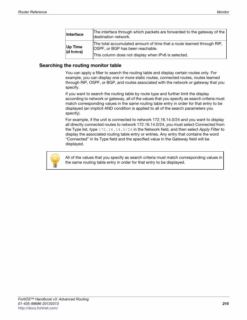
Router Reference Monitor
F
0
h
Searching the routing monitor table
You can apply a filter to search the routing table and display certain routes only. For
example, you can display one or more static routes, connected routes, routes learned
through RIP, OSPF, or BGP, and routes associated with the network or gateway that you
specify.
If you want to search the routing table by route type and further limit the display
according to network or gateway, all of the values that you specify as search criteria must
match corresponding values in the same routing table entry in order for that entry to be
displayed (an implicit AND condition is applied to all of the search parameters you
specify).
For example, if the unit is connected to network 172.16.14.0/24 and you want to display
all directly connected routes to network 172.16.14.0/24, you must select Connected from
the Type list, type 172.16.14.0/24 in the Network field, and then select Apply Filter to
display the associated routing table entry or entries. Any entry that contains the word
“Connected” in its Type field and the specified value in the Gateway field will be
displayed.
InterfaceThe interface through which packets are forwarded to the gateway of the
destination network.
Up Time
(d h:m:s)
The total accumulated amount of time that a route learned through RIP,
OSPF, or BGP has been reachable.
This column does not display when IPv6 is selected.
All of the values that you specify as search criteria must match corresponding values in
the same routing table entry in order for that entry to be displayed.
ortiOS™ Handbook v3: Advanced Routing
1-435-99686-20120313 215
ttp://docs.fortinet.com/

Monitor Router Reference
Advanced Routing for FortiOS 4.0 MR3
216 01-435-99686-20120313
http://docs.fortinet.com/
F o r t i O S H a n d b o o k
F
0
h
Index
A
access control list (ACL), 21
adding, configuring definingadvanced RIP options, 195BFD, 211BGP, 206changing gateway for default route (static route), 188dead gateway detection, 191ECMP load balancing method, 191multicast, 209OSPF areas, 201OSPF basic settings, 198OSPF interface, operating parameters, 203OSPF networks, 202OSPF settings, advanced, 200policy route, 189RIP, 194RIP enabled interface, 197RIP settings, advanced, 195RIP-enabled interface, 197static route to routing table, 189static route, adding to routing table, 189static routes, 187
adding, configuring or definingpolicy route, 36
administrative distance, 23, 24
anti-spoofing, 23
area, 138
area border router (ABR), 201
ASmultihomed, 51number (ASN), 51stub, 51
authenticationMD5, 202RIP, 197
autonomous system (AS), 204
B
BFDdisabling, 212disabling, interface, 212
BGPAS, 204configuring, 206RFC 1771, 204RFC 2385, 204
bgpattribute
AS_PATH, 99
ATOMIC_AGGREGATE, 101
COMMUNITY, 100
MULTI_EXIT_DESC, 100
NEXT_HOP, 101BGP-4+, 93clearing routes, 95, 105control plane, 107flap, 107graceful restart, 107MED, 100neighbors, 95password, MD5, 95RFC 1997, 101route reflectors (RR), 97stabilizing the network, 107
Bi-directional Forwarding Detection (BFD), 108
blackhole route, 22
C
Classless Inter-Domain Routing (CIDR), 42
control plane, 107
convergence, 41, 109
D
dampening, 107reachability half-life, 107
dead gateway detection, 70, 175, 191
default gateway, 188
default route, 188
dense mode, 208
Dijkstra’s algorithm, 140
distance vector protocols, 43
DNATmulticast service reflection, 210
dotted-decimal notation, 201
ortiOS™ Handbook v3: Advanced Routing
1-433-98043-20120116 217
ttp://docs.fortinet.com/
Index
dynamic routing, 193access list, 212BGP, configuring, 206Bi-directional forwarding detection (BFD), 211disabling BFD for an interface, 212multicast, configuring, 209OSPF, 198OSPF networks, 202OSPF, advanced, 200OSPF, defining areas, 201OSPF, operating parameters for interface, 203PIM, 207RIP, 194RIP enabled interface, 197RIP, advanced, 195
E
ECMP, 22
ECMP load balancing, 191
enhanced packet-matching, 53
Equal Cost Multipath (ECMP), 22
equal cost multipath (ECMP), 25
equal-cost multi-path (ECMP), 27
Exterior Gateway Protocol (EGP), 93
exterior gateway protocol (EGP), 43
G
graceful restart, 107
GRE, 197
H
HA, 105router monitor, 16routes, 16
I
IGMPRFC 1112, 208RFC 2236, 208RFC 3376, 208
interfaceGRE, 197loopback, 22
interfacesdisabling BFD, 212
interior gateway protocol (IGP), 43
Internet Assigned Numbers Authority (IANA), 51
IP, protocol 89, 138
IPsec, 197
L
link-state advertisement (LSA), 44
loopback interface, 22
M
Martian addresses, 23
MD5OSPF authentication, 202
missing MED, 100
monitorrouting, 213
monitoringrouting table, 213
multicast, 207configuring, 209dense mode, 208DNAT, 210IGMP, 208
multicast destination NAT, 210
Multi-Exit Discriminator (MED), 100
Multipath routing, 23
N
NATmulticast, 210
Not-so-stubby Area (NSSA), 201
not-so-stubby area (NSSA), 17, 214
O
OSPFadvanced, 200area ID, 203areas, 201AS, 199authentication, 202configuring, 198Dead Interval, 204dead packets, 204network, 199networks, 202NSSA, 201, 214operating parameters for interface, 203regular area, 201settings, 198stub, 201virtual lan, 203virtual link, 201
ospfadjacent routers, 139, 144area, 138area border router (ABR), 138Dijkstra’s algorithm, 140e1, 17e2, 17Hello packets, 138Hello protocol, 139IP datagrams, 138link-state, 138neighbor, 139NSSA, 17path cost, 140state of neighbor, 144
OSPF ASdefining, 198
ospf AS, 134
Advanced Routing for FortiOS 4.0 MR3
218 01-433-98043-20120116
http://docs.fortinet.com/
Index
F
0
h
P
PIMdense mode, 207RFC 2362, 207RFC 3973, 207sparse mode, 207
policy routemoving in list, 38
policy-based routing, 189
port 179, 102
protocolospf Hello, 139
Protocol Independent Multicast (PIM), 207
R
redistributed routesospf e1/e2, 17
Reverse Path Forwarding (RPF), 210
reverse path lookup, 23
RFC1349, 375237, 36791, 37RFC 1519, 42RFC 1771, 93RFC 1965, 98RFC 1966, 97RFC 1997, 101RFC 2385, 95RFC 2453, 57RFC 3065, 98RFC 3509, 141RFC 4271, 93RFC 4632, 42
RFC 1112, 208
RFC 1321, 202
RFC 1771, 204
RFC 2236, 208
RFC 2362, 207
RFC 2385, 204
RFC 3376, 208
RFC 3973, 207
RFC 5237, 190
RIPadvanced options, 195authentication, 197configuring, 194hop count, 63interface, 197RFC 1058, 57RFC 2453, 57RIP Next Generation (RIPng), 58split horizon, 197version 1, 57version 2, 57
route flap, 107HA, 105
route reflectors (RR), 97
routersettings, 191
router monitorHA, 16
routingadministrative distance, 23blackhole, 22domain, 51ECMP, 22enhanced packet-matching, 53loopback interface, 22monitor, 213routing table, searching, 19static, 185viewing information, 15
routing policyprotocol number, 36, 190
routing table, 141removing routes, 95searching, 215
RPF, 210
S
searchingrouting table, 215
Shortest Path First (SPF), 140
Spill-over, 31
static routeadding, 189adding policy, 36administrative distance, 23changing gateway for default route, 188creating, 185default gateway, 188default route, 188default route and gateway, 188editing, 185moving in list, 38overview, 185policy, 189policy list, 189table priority, 24, 28table sequence, 24, 28viewing, 185
static routesdistance, 188priority, 188
stubOSPF area, 201
supernetting, 99
T
troubleshootingBFD, 108bgp, 105dampening, 107graceful restart, 107holddown timer, 106route flap, 105routing table, 26
Type of service (TOS), 37
ortiOS™ Handbook v3: Advanced Routing
1-433-98043-20120116 219
ttp://docs.fortinet.com/ • Feedback

Index
U
unicast reverse path forwarding (uRPF), 14
usage-based ECMP, 31
V
viewingrouting information, 213static route, 185
VLANOSPF, 203
Advanced Routing for FortiOS 4.0 MR3
220 01-433-98043-20120116
http://docs.fortinet.com/