Embed Size (px)
Citation preview

Advanced Envelope Research for Factory Built Housing, Phase 3—Design Development and Prototyping E. Levy, B. Kessler, M. Mullens, and P. Rath ARIES Collaborative
January 2014
i
NOTICE
This report was prepared as an account of work sponsored by an agency of the United States government. Neither the United States government nor any agency thereof, nor any of their employees, subcontractors, or affiliated partners makes any warranty, express or implied, or assumes any legal liability or responsibility for the accuracy, completeness, or usefulness of any information, apparatus, product, or process disclosed, or represents that its use would not infringe privately owned rights. Reference herein to any specific commercial product, process, or service by trade name, trademark, manufacturer, or otherwise does not necessarily constitute or imply its endorsement, recommendation, or favoring by the United States government or any agency thereof. The views and opinions of authors expressed herein do not necessarily state or reflect those of the United States government or any agency thereof.
Available electronically at http: //www.osti.gov/bridge
Available for a processing fee to U.S. Department of Energy and its contractors, in paper, from:
U.S. Department of Energy Office of Scientific and Technical Information
P.O. Box 62 Oak Ridge, TN 37831-0062
phone: 865.576.8401 fax: 865.576.5728
email: mailto: [email protected]
Available for sale to the public, in paper, from: U.S. Department of Commerce
National Technical Information Service 5285 Port Royal Road Springfield, VA 22161 phone: 800.553.6847
fax: 703.605.6900 email: [email protected]
online ordering: http: //www.ntis.gov/ordering.htm
Printed on paper containing at least 50% wastepaper, including 20% postconsumer waste

iii
Advanced Envelope Research for Factory Built Housing Phase 3—Design Development and Prototyping
Prepared for:
The National Renewable Energy Laboratory
On behalf of the U.S. Department of Energy’s Building America Program
Office of Energy Efficiency and Renewable Energy
15013 Denver West Parkway
Golden, CO 80401
NREL Contract No. DE-AC36-08GO28308
Prepared by:
E. Levy, B. Kessler, M. Mullens, and P. Rath
ARIES Collaborative
The Levy Partnership, Inc.
1776 Broadway, Suite 2205
New York, NY 10019
NREL Technical Monitor: Michael Gestwick
Prepared under Subcontract No. KNDJ-0-40347-03
January 2014

iv
[This page left blank]
v
Contents List of Tables ............................................................................................................................................ viii Definitions ................................................................................................................................................... ix Acknowledgments ...................................................................................................................................... x Abstract ....................................................................................................................................................... xi Executive Summary .................................................................................................................................. xii 1 Introduction ........................................................................................................................................... 1
1.1 Background ..........................................................................................................................1 1.2 Project Scope .......................................................................................................................3 1.3 Research Partners .................................................................................................................3
1.3.1 Steering Committee .................................................................................................4 1.3.2 Insulation Manufacturers .........................................................................................4 1.3.3 ARIES Technical Team ...........................................................................................5
1.4 Research Process ..................................................................................................................5 1.5 Research Questions ..............................................................................................................6
2 Mathematical and Modeling Methods ................................................................................................. 8 2.1 Thermal Modeling and Cost-Benefit Analysis ....................................................................8 2.2 Moisture Analysis ................................................................................................................8
3 Research/Experimental Methods ........................................................................................................ 9 3.1 Racking Test ........................................................................................................................9
3.1.1 Test Specimen Sampling..........................................................................................9 3.1.2 Test Procedure .........................................................................................................9
3.2 Wall Panel Mockup Demonstration .....................................................................................9 3.3 Window Framing Evaluation .............................................................................................10 3.4 Testing Apparatus ..............................................................................................................10
4 Results: Phase 3—Design Development and Prototyping ............................................................. 12 4.1 Overview of the Advanced Envelope Research Concept—Stud Walls With Continuous
Exterior Insulation .............................................................................................................12 4.2 Design Development ..........................................................................................................17
4.2.1 AFM Corporation...................................................................................................17 4.2.2 BASF Corporation .................................................................................................20 4.2.3 The Dow Chemical Company ................................................................................26 4.2.4 Johns Manville Corporation ...................................................................................28 4.2.5 Saint-Gobain/CertainTeed .....................................................................................32
4.3 Production Analysis ...........................................................................................................35 4.4 Thermal and Cost Benefit Analysis ...................................................................................36 4.5 Moisture Analysis ..............................................................................................................38 4.6 Prototyping and Testing .....................................................................................................41
4.6.1 Location and Participants .......................................................................................42 4.6.2 Racking Tests .........................................................................................................42

vi
4.6.3 Process Mockup Evaluation and Observation .......................................................43 4.6.4 Window Construction Assessment ........................................................................44
5 Discussion ........................................................................................................................................... 46 5.1 Stud Walls With Styrofoam ...............................................................................................46
5.1.1 Construction Detailing ...........................................................................................46 5.1.2 Installing Windows and Doors ...............................................................................47 5.1.3 Fasteners ................................................................................................................49 5.1.4 Assembly/Production .............................................................................................51 5.1.5 Racking Test Results..............................................................................................53
5.2 Stud Walls With Foam-Control Nailbrace .........................................................................56 5.2.1 Construction Detailing ...........................................................................................57 5.2.2 Installing Windows and Doors ...............................................................................58 5.2.3 Fasteners ................................................................................................................61 5.2.4 Assembly/Production .............................................................................................64
6 Conclusions ........................................................................................................................................ 67 References ................................................................................................................................................. 69 Appendix A: Detailed Test Description ................................................................................................... 71 Appendix B: Equipment and Material Needs ......................................................................................... 76

vii
List of Figures Figure 1. Plan view of testing apparatus ................................................................................................ 10 Figure 2. Front elevation (left) and side elevation (right) of testing apparatus .................................. 11 Figure 3. Corner detail of testing apparatus .......................................................................................... 11 Figure 4. Stud wall with exterior insulation, Design 1 (climate zone 5) .............................................. 16 Figure 5. Stud wall with exterior insulation, Design 2 (climate zones 6, 7, and 8) ............................. 17 Figure 6. Stud wall with exterior insulation, Design 3 (climate zones 6, 7, and 8) ............................. 17 Figure 7. Foam-Control Nailbrace Concept A, Design 1 (climate zone 5) ........................................... 18 Figure 8. Foam-Control Nailbrace Concept A, Design 2 (climate zones 6, 7, and 8) ......................... 18 Figure 9. Foam-Control Nailbrace with let-in bracing (without WRB) ................................................. 18 Figure 10. Foam-Control Nailbrace - top view (without WRB) .............................................................. 18 Figure 11. NEOPOR Concept A, Design 1 (climate zone 5) .................................................................. 21 Figure 12. NEOPOR Concept A, Design 2 (climate zones 6, 7, and 8) ................................................. 21 Figure 13. NEOPOR Concept B, Design 1 (climate zone 5) .................................................................. 21 Figure 14. NEOPOR Concept B, Design 2 (climate zones 6, 7, and 8) ................................................. 21 Figure 15. NEOPOR Concept C, Design 1 (climate zone 5) .................................................................. 22 Figure 16. NEOPOR Concept C, Design 2 (climate zones 6, 7, and 8) ................................................. 22 Figure 17. NEOPOR Concept D, Design 1 (climate zone 5) .................................................................. 22 Figure 18. NEOPOR Concept D, Design 2 (climate zones 6, 7, and 8) ................................................ 22 Figure 19. NEOPOR R-value at 75°F and 40°F ....................................................................................... 25 Figure 20. Stud wall with Styrofoam, Design 1 (climate zone 5) ......................................................... 27 Figure 21. Stud wall with Styrofoam, Design 2 (climate zones 6, 7, and 8) ....................................... 27 Figure 22. ValuTherm Concept A (climate zones 5, 6, 7, and 8) ........................................................... 29 Figure 23. AP foil-faced sheathing Concept B (climate zones 5, 6, 7, and 8) ..................................... 29 Figure 24. SIS sheathing Concept C (climate zones 5, 6, 7, and 8) ..................................................... 29 Figure 25. Stud wall with faced CertaPro, Design 1 (climate zone 5) .................................................. 33 Figure 26. Stud wall with faced CertaPro, Design 2 (climate zones 6, 7 and 8) .................................. 33 Figure 27. WUFI results for wall with R-10 (2 in. XPS) insulation in International Falls .................... 40 Figure 28. WUFI results for wall with R-5 (1 in. XPS) insulation in International Falls ...................... 41 Figure 29. Detail 1—Window frame bearing on foam ............................................................................ 44 Figure 30. Detail 2—Window framing with buck lumber ....................................................................... 45 Figure 31. Detail 3—Window framing with metal L-section .................................................................. 45 Unless otherwise noted, all figures were created by the ARIES team.

viii
List of Tables Table 1. Desired Properties of Advanced Wall Designs With Composite Insulative Sheathing ....... 13 Table 2. Foam-Control Nailbrace—Sizes and Weights ......................................................................... 19 Table 3. NEOPOR—Physical Properties ................................................................................................. 23 Table 4. R-Value of NEOPOR Rigid Thermal Insulation ........................................................................ 24 Table 5. NEOPOR—Sizes and Weights ................................................................................................... 25 Table 6. Styrofoam—Sizes and Weights ................................................................................................. 28 Table 7. JM Products—Physical Properties ........................................................................................... 30 Table 8. ValuTherm—Sizes and Weights ................................................................................................ 31 Table 9. AP Foil-Faced Insulation—Sizes and Weights ........................................................................ 31 Table 10. AP Foil-Faced Insulation—Weather Resistive Properties .................................................... 32 Table 11. CertaPro—Physical Properties ............................................................................................... 34 Table 12. CertaPro—Sizes and Weights ................................................................................................. 35 Table 13. Impact Summary—Work Content ........................................................................................... 36 Table 14. Allowable Cost of Insulative Sheathing To Qualify as Cost Effective ................................ 37 Table 15. Comparison of U-Values .......................................................................................................... 38 Table 16. Racking Tests—Stud Walls With Styrofoam ......................................................................... 43 Table 17. Racking Tests—Stud Walls With Foam-Control Nailbrace .................................................. 43 Table 18. Process Mockups—Stud Walls With Styrofoam ................................................................... 43 Table 19. Process Mockups—Stud Walls With Foam-Control Nailbrace ............................................ 44 Table 20. Racking Test Results—Stud Walls With Styrofoam ............................................................. 54 Table 21. Racking Test Results—Stud Walls With Foam-Control Nailbrace ...................................... 65 Table 22. Details on Racking Tests—Stud Walls With Styrofoam ....................................................... 72 Table 23. Details on Racking Tests—Stud Walls With Foam-Control Nailbrace ................................ 73 Table 24. Details on Mockups—Stud Walls With Styrofoam ................................................................ 74 Table 25. Details on Mockups—Stud Walls With Foam-Control Nailbrace ......................................... 75 Table 26. Fasteners and Associated Tools (Senco Products) ............................................................. 76 Table 27. Fasteners and associated tools (FastenMaster products) ................................................... 77 Unless otherwise noted, all tables were created by the ARIES team.

ix
Definitions
BEopt Building Energy Optimization
CI Continuous insulation
EPS Expanded polystyrene
XPS Extruded polystyrene
HUD U.S. Department of Housing and Urban Development
IECC International Energy Conservation Code
IRC International Residential Code
JM Johns Manville
N/A Not available
OEM Original equipment manufacturer
OSB Oriented strand board
pcf per cubic foot
plf per linear foot
RD&D Research, design, and development
SIP Structural insulated panel
VR Vapor retarder
WRB Weather resistive barrier
WUFI Wärme und Feuchte instationär (Transient heat and moisture)

x
Acknowledgments
ARIES Collaborative would like to recognize the support of the U.S. Department of Energy’s Building America Program and Michael Gestwick of the National Renewable Energy Laboratory for technical guidance. We also would like to acknowledge the research direction provided by the factory built housing industry represented by leading home manufacturers. We were fortunate to have some of the prominent insulation manufacturers of the nation weighing in on the credibility of the technology options to make them more viable and cost effective.

xi
Abstract
The Advanced Envelope Research effort will provide factory homebuilders with high performance, cost-effective alternative envelope designs. In the near term, these technologies will play a central role in meeting more stringent energy code requirements. For manufactured homes, the thermal requirements, last updated by statute in 1994, will move up to the more rigorous International Energy Conservation Code (IECC) 2012 levels in 2013, the requirements of which are consistent with site built and modular housing. This places added importance on identifying envelope technologies that the industry can implement in the short timeframe. The primary goal of this research is to develop wall designs that meet the thermal requirements based on 2012 IECC standards. Given the affordable nature of manufactured homes, impact on first cost is a major consideration in developing the new envelope technologies.1
This work is part of a four-phase, multiyear effort. Phase 1 identified seven envelope technologies and provided a preliminary assessment of three selected methods for building high performance wall systems. Phase 2 focused on the development of viable product designs, manufacturing strategies, addressing code and structural issues, and cost analysis of the three selected options. An industry advisory committee helped critique and select the most viable solution to move further in the research—stud walls with continuous exterior insulation. Phase 3, the subject of the current report, focused on the design development of the selected wall concept and explored variations on the use of exterior foam insulation. The scope also included material selection, manufacturing and cost analysis, and prototyping and testing. Phase 4, starting in 2013, will complete the testing, cull down to designs with the greatest market potential, and begin to clear the code, production, and design hurdles to commercial use.
Key words
Factory built housing Manufactured housing Modular housing Research, design, and development Advanced envelope research Energy efficiency Envelope technology Advanced wall strategy Walls with exterior sheathing Continuous exterior insulation
1 First cost impacts are more meaningful for buyers of modestly priced homes and therefore decisions about efficiency measures must be made in light of both impact on cost and cost effectiveness.

xii
Executive Summary
The Advanced Envelope Research project seeks to improve the energy performance of new factory built homes. Factory building divides into manufactured and modular homes. Most factory built homes are termed “manufactured” and are constructed under the nationally pre-emptive manufactured housing standards (referred to as the U.S. Department of Housing and Urban Development standards), which were last updated in 1994. The U.S. Department of Energy is currently working on changes to these standards that are anticipated to be enacted in 2013 and are expected to be based on IECC 2012. The industry currently has no broadly implemented, competitive options for meeting the anticipated thermal provisions of these standards. Modular homes are built in a factory using methods that are similar to, or the same as, manufactured homes. Modular homes generally meet the same state-based energy standards as site built homes, standards that are also in the process of becoming more stringent.
In response, this effort is intended to create and demonstrate new envelope design and building practices that are cost effective, that can be successfully applied in a factory setting, and that result in substantial reductions in energy use. This research will yield new practices for building envelope components that meet these criteria and initiate the process of moving these practices into commercial use.
The primary goal of this research is to achieve a target wall thermal value based on future code requirements. The current work is part of a multiyear development effort, divided into four phases. Phase 3, the subject of this report, focused on the design development, prototyping, and testing of high performance wall systems sharing a common characteristic: all employed stud wall construction with continuous exterior insulation. The research involves key industry stakeholders as active partners whose input and contribution to the effort are integral to accomplishing the project goals. Major stakeholders in Phase 3 included insulation manufacturers, companies that eventually will be suppliers of products specified for the options and the factory built home manufacturers that are the end users. Insulation companies played a key role in the design development. Selected designs were prototyped and tested at a partner manufacturing plant. Key results include performance analysis and selection of designs that will move forth to the next phase of the project. With the impending code changes, the factory built manufacturing companies are keen to see the research result in cost-effective solutions that could be taken to market quickly. In short, all of the stakeholders are heavily invested in seeing this work succeed and the results put into practice.

1
1 Introduction
The Advanced Envelope Research project seeks to improve the energy performance of new factory built homes, a segment of the housing industry that accounts for about 12%–14% of the nation’s total annual housing sales.2 The largest segment of the factory building industry, manufactured homes, historically has had to meet energy standards less stringent than current International Energy Conservation Code (IECC)-based codes. As a consequence, the industry has evolved few cost-effective options for reaching ambitious energy efficiency targets, such as the Building America goals. This research, design, and development (RD&D) effort will fill this void by creating and demonstrating new design and building practices that minimize cost, that can successfully be applied in a factory setting, and that result in substantial reductions in energy use. The research will yield new practices for building envelope components that meet these criteria and initiate the process of moving these practices into commercial use.
The majority of factory built housing manufacturers have been slow to adopt new building products and technologies on their own for many reasons, including: (1) the development costs are prohibitively high for any single manufacturer; (2) developing proprietary envelope solutions would be difficult to defend in the market, meaning that the RD&D investment by one company would benefit competitors; and (3) while most companies have engineering staff, they lack a tradition of building technology RD&D and are ill-equipped to conduct the type of cross cutting research that involves the complex set of interrelated technical issues envisioned for this project.
Success of the proposed work—the demonstration of how advanced envelope designs can replace conventional frame construction without a significant impact on total cost—will yield cornerstone technologies the industry will need in moving toward the nation’s ambitious energy efficiency goals. While the results of this research will have immediate application to manufactured homes, the technologies developed will have relevance for modular construction as well. Modular homes are subject to similar factory construction issues and manufacturing constraints and generally have a higher price point than manufactured housing, allowing for greater design flexibility.
1.1 Background Lacking the regulatory pressures that would necessitate high performance envelope designs and marketing homes to buyers with little discretionary buying power, the factory built housing has been slow to develop envelope construction practices that approach Building America targets. As a result, the industry has few proven and cost-effective building solutions for responding to a fast changing marketplace that is demanding greater energy efficiency and impending regulatory changes that will require them.3
2 Estimate derived from the National Modular Housing Council’s Quarterly Modular Housing Report and the Manufactured Housing Institute’s Monthly Economic Reports (2010). Source of the reports— www.manufacturedhousing.org/reports/ (available to Manufacturing Housing Institute members only). The percentage share shown is new factory built homes relative to the number of total new houses sold. This figure is in terms of number of housing units. 3 The modular housing industry has limited prior experience building walls with continuous exterior insulation, the focus of this research effort. One of the project goals is to develop simple designs with few materials that perform

2
Most factory built homes are constructed under the nationally pre-emptive manufactured housing standards (also referred to as the U.S. Department of Housing and Urban Development [HUD] standards). The thermal provisions of the standards were last updated in 1994 (HUD 1994). As a result, manufactured housing currently lags behind other types of housing in terms of energy performance, particularly in states that routinely adopt the most recent version of the IECC. The U.S. Department of Energy is currently working on changes to the HUD standards that are anticipated to set the bar for performance based on the IECC 2012, that, when implemented, are expected to result in major changes in how the industry approaches thermal envelope design and construction.
Although the potential benefits of proving high performance envelope component designs for factory application are huge, the technical hurdles for factory builders are formidable. Implementing changes to envelope components can engender a host of major changes in plant layout, workflow, materials handling, and safety issues. Potentially, some of the proposed changes would increase production rates while improving quality, magnifying the benefits of this research. Other elements of the needed research include assessing the impact of changes on structural performance, moisture dynamics, integration of services, and code acceptance. This research effort sets the stage for elevating factory production to address these factors and fully and seamlessly incorporating advanced methods into the industrialized building fabric.
The home building industry generally lacks a tradition of research, and home manufacturers in particular have limited internal expertise and capacity to develop new technologies. Further constraining individual companies is the lack of discretionary spending on new product development due, in part, to the massive losses that every company has suffered over the last decade. As noted, the dynamics have changed and the industry must now find cost-effective and high performance envelope solutions to meet future code requirements and market pressures.
The industry’s initial attempts to develop cost-effective approaches to improving energy performance (including the use of structural insulated panels [SIPs] and other open and closed cell insulation products) convinced many in the industry that such technologies have the potential to revolutionize manufacturing practice. However, the resources (financial and technical) needed to tackle the myriad interrelated challenges are well beyond the capacity and skills of a single or even a group of manufacturers. The other drag on innovation is the fact that the industry is highly competitive and advances underwritten by a single company are readily adopted by other manufacturers, diluting the value of the research investment. Patents are few and expensive to defend, in part explaining why most buildings-related research is conducted by product manufacturers, not home building companies.
This work initiates a new direction for Building America activities. Introducing new envelope construction practices in a factory setting will provide valuable insights into how high performance products can be applied to home building, yielding new measure guidelines and potentially identifying practices that can be used by site and componentized homebuilders.
multiple functions minimizing the number of individual products that must be purchased, inventoried, and installed by the plant, saving cost in both handling and main line construction time.
3
1.2 Project Scope The study is exclusively focused on advancing envelope design’ and the current work is part of a multiphase effort to improve the performance of wall components. The team recognizes that having viable and cost-effective envelope technologies is a prerequisite in formulating whole building solutions. The current research effort focuses on factory built homes located in IECC 2009 climate zones 5 and higher. Insulation requirements underwent significant changes for these northern, primarily heating-dominated climate zones that will benefit most from these research findings.
The approach to the project and scope is shaped by the following three overarching considerations:
1. Minimize cost, maximize performance: One of the major challenges in the development process is creating a product design and fabrication method that minimizes total cost while maximizing product performance. The product and process designers each start with a set of goals but must engage in a development process that arrives at a common, integrated, and optimized solution. The process of bringing diverse goals to a common development process, in which several disciplines simultaneously re-engineer the building product and process and work to integrate and synergize their solutions, is often referred to as concurrent engineering.4
2. Reinvent the whole system: This research work is being driven by the unique requirements of factory homebuilding. Researchers seek synergies among building materials, automated production equipment, and information technology. Then, guided by the principles of lean production, researchers will explore how the whole system can be reinvented to dramatically improve quality, energy efficiency, safety, cost effectiveness,5 productivity, and design flexibility.
3. System integration: In all homes, but particularly in factory built housing, performance of systems, subsystems, and components is dependent on other systems within the structure, and improving performance in one area has collateral impacts elsewhere. For example, changes in the envelope subsystem intended to improve energy efficiency may affect the production process and may alter the structural characteristics of the home. Optimization of any single part of the home therefore depends on balancing considerations elsewhere. The team employs a systems approach designed to find combinations of changes that together improve overall performance when gauged relative to an objective baseline.
1.3 Research Partners This effort is cooperatively sponsored by the Systems Building Research Alliance. Technical direction is provided by an industry-led Steering Committee acting under the Systems Building Research Alliance umbrella and consisting mainly of factory building company representatives. 4 Concurrent engineering benefits factory built housing more than other less industrialized forms of housing for several reasons, including the fact that the economics of the plant construction process are far more dependent upon speed, coordination of trades, and dimensional precision. In addition, quality control and coordination of the trades is more easily accomplished in the factory than at the building site. 5 Cost effectiveness is a general expression intended to convey that costs and benefits have been balanced using some generally accepted econometric process.

4
Participating insulation manufacturers are key contributors to the work and the concepts developed. ARIES team members facilitate the work and provide technical support, analysis, evaluation and documentation. Members of the research team are listed below:
1.3.1 Steering Committee Michael Wade, Cavalier Homes, Committee chair Ronnie Richards, American Homestar Corp. Jayar Daily, American Homestar Corp. John Meredith, Beracah Homes, Inc. Jerome Alexander, BlueLinx Corporation Mark Klaus, Cavco Industries, Inc. Manuel Santana, Cavco Industries, Inc. Phillip Copeland, Champion Home Builders, Inc. David French, Champion Home Builders, Inc. Bill Stamer, Champion Home Builders, Inc. Tony Watson, Champion Home Builders, Inc. Mark Ezzo, Clayton Homes Gary Butler, Commodore Homes, Inc. Nader Tomasbi, Commodore Homes, Inc. Robert Bender, Commodore Homes, Inc. Jim Dunn, Eagle River Homes, Inc. Alan Behrent, Excel Homes, Inc. Delma Sheaffer, Excel Homes, Inc. Bill Langdon, Forest River Housing, Inc. Luca Brammer, Hallmark—Southwest Corp. Mark Tackett, Louisiana Pacific Corporation Lois Starkey, Manufactured Housing Institute Mike Clementoni, Muncy Homes, Inc. Rich Bird, Muncy Homes, Inc. Woody Bell, Nationwide Custom Homes Andy Miller, Nationwide Custom Homes Eric Tompos, NTA, Inc. Bert Kessler, Palm Harbor Homes Bryan Huot, Preferred Building Systems Richard Shives, Premier Builders Terry Dullaghan, Senco
1.3.2 Insulation Manufacturers Mike Tobin, AFM Corp. Paul Fox, BASF Brian Lieburn, Dow Corp. Bryan Mallon, Dow Corp. Francis Babineau, Johns Manville Corp. Craig Marden, Owens Corning Daniel Small, Saint-Gobain/CertainTeed

5
1.3.3 ARIES Technical Team Emanuel Levy, The Levy Partnership, Inc. Michael Mullens, The Levy Partnership, Inc. Pournamasi Rath, The Levy Partnership, Inc.
1.4 Research Process The research will develop the next generation of envelope component designs for the factory building industry. This work consists of identifying alternative options, critically evaluating their potential to meet a set of performance goals, selecting option(s) for development, developing a design/engineering solution for the option(s), and testing and evaluation. The project spans several years and is divided into four phases as follows:
Phase 1. Identification and characterization of options. Completed in 2011, this phase identified a wide range of innovative envelope technologies that were culled down to a short list of three methods for building high performance wall systems.
Phase 2. Preliminary design. Completed in January 2012, Phase 2 focused on the development of viable product designs, manufacturing strategies, addressing code and structural issues, and cost analysis of the three innovative wall concepts. An industry advisory committee was convened to help critique and select the most viable solution.
Phase 3. Design development and prototyping. Phase 3, the subject of the current report, focused on design development exploring variations on the use of exterior foam insulation, one of the three core concepts. The scope of work also included material selection, manufacturing and cost analysis, and prototyping and testing.
Phase 4. Proof of concept and market readiness. Phase 4, scheduled to start in late-2013, will complete the testing of wall designs that feature exterior foam insulation. The work will identify designs with the greatest market potential, and begin to clear the code, production, and design hurdles to commercial use.
The research methods and results of Phases 1 and 2 are discussed in detail by Levy et al. (2012).
Phase 1 of the Advanced Envelope Research was initiated by an industry advisory committee meeting held in early 2011. Leading insulation companies were invited to present envelope solutions with project potential. The presentations provided numerous ideas that were debated and discussed by the industry advisory committee. The concepts were honed by the ARIES team and narrowed to a short list of seven candidate technologies, as follows:
• SIPs for ceilings • SIPs for walls • Stud wall with insulating sheathing board • Unvented attic with continuous exterior insulation • Flash and batt wall construction • Poured closed cell foam • Innovative new floor design.
6
Following a preliminary design development of the seven identified options, a qualitative assessment pinpointed the benefits and drawbacks of each of the technologies when used in the factory building setting. Criteria for comparison included energy performance, manufacturability, code compliance, and cost. The advisory committee and industry experts rated the options and selected the following for subsequent research:
• SIPs for walls • Stud walls with continuous exterior insulation • Flash and batt wall construction.
In Phase 2, the three concepts were further developed and refined. The characterizations provided sufficient detail to allow a detailed assessment of the costs associated with adopting the technology, impact on current manufacturing processes, value of the technology in helping to comply with stringent energy codes (now and in the future), market appeal, and other attributes essential for commercial acceptance. The research in this phase included a “base case” wall design that would likely be used by industry in the absence of an advanced solution to meet stringent energy standards.
The ARIES technical team and the industry advisory committee discussed the findings, identifying those that were most cost effective and had potential wide market appeal and application (potentially attractive to most manufacturers). Subsequently, one technology—based on the use of continuous exterior sheathing combined with batt insulation—was deemed by the committee as having the greatest commercial potential. The analysis of SIPs helped the industry representatives recognize that this technology has real advantages that were not manifest when used for wall construction, but that might be viable for other components. The committee also concluded that a major redesign of the roof and floor system used by most builders of manufactured homes continues to be a crucial part of the effort to improve overall envelope thermal performance. Further developing the wall with exterior insulative sheathing is the subject of the current work which includes exploring variations on the use of different insulation products resulting in multiple wall assembly combinations.
1.5 Research Questions This phase of the research sought to answer the following questions:
• What options exist for building wall components that incorporate off-the-shelf or readily developable insulative sheathing materials that minimize cost, substantially improve thermal performance and leverage the inherent efficiencies of factory production?
• What are the detailed performance characteristics of such a wall system?
• How do these options compare with regard to structural properties? Specifically, how can they contribute to wall shear resistance?
• For walls with insulative sheathing, what are the preferred strategies for controlling moisture when used in a factory built assembly? In particular, what are the desired vapor retarder (VR) properties of the materials and how is this best achieved through design and product fabrication and assembly?

7
• What are the major technical hurdles to using insulative sheathing in the factory environment? To what extent can these barriers be surmounted by further research and product development?

8
2 Mathematical and Modeling Methods
2.1 Thermal Modeling and Cost-Benefit Analysis Thermal modeling and cost-benefit analysis were performed using BEopt (Building Energy Optimization), software developed by the National Renewable Energy Laboratory for the purpose of selecting among measures based on their relative cost effectiveness. However, one of the primary goals of research is to achieve a fixed wall thermal value based on future code requirements. Therefore, the measure value (thermal resistance) was fixed and BEopt was instead used to identify a target cost, a figure that would meet predefined cost-benefit goals while achieving the stipulated measure thermal value. Of course, the effort was designed to leverage factory building methods in ways that minimize costs, recognizing that the target wall thermal values were fixed by statute and that even at the lowest achievable cost the measure might not be cost effective. Results of the analysis are provided in Section 4.4.
2.2 Moisture Analysis WUFI (Wärme und Feuchte instationär), used for moisture analysis, is a software family that allows realistic calculation of the transient coupled one- and two-dimensional heat and moisture transport in multilayer building components exposed to natural weather (ORNL 2013). It was developed by Institut Bauphysik and is based on the newest findings regarding vapor diffusion and liquid transport in building materials. The research is being conducted in the context of different regulatory frameworks for modular and manufactured homes. Modular homes must meet the same code as site built homes. While the requirement varies by location, generally the prevailing code requirements are based on a version of the International Residential Code (IRC). Manufactured homes conform to the HUD Standards. In selecting wall characteristics, researchers identified a provision in the IRC (Section R702.7) that eliminates the Class I or II VR requirement on the interior (a cost saving measure) if, among other conditions, exterior insulated sheathing is used. (While this provision is not currently provided for in the HUD Standards, the current research and work of other Building America teams could provide the technical basis for recommending to HUD a future change in the standards.) Therefore, part of the purpose of the moisture analysis was to assess how moisture flow is impacted if the interior materials provide little resistance to vapor transmission (Class III) coupled with exterior materials that can be Class I, II, or III VRs. Results of the analysis are provided in Section 4.5.

9
3 Research/Experimental Methods
Experimental methods for this research project comprised the following tests/evaluation methods:
• Racking test to evaluate structural capacity • Wall panel mock-up demonstration • Window framing assessment.
Multiple iterations of each selected wall option were subject to testing and mockups.
3.1 Racking Test A racking test was performed on developed wall designs to evaluate structural compliance with ASTM E72-80 or E564 as required for compliance under the HUD standards. The objective of the test was to determine the ultimate racking capacity of a framed shearwall with or without gypsum board adhered to one side and siding nailed to the opposite side.
3.1.1 Test Specimen Sampling The racking tests were performed along the lines of the ASTM E564 testing protocol. Unlike the ASTM sampling protocol where the procedure is performed on three test specimens, testing for this research project was performed on one specimen wall only (but there were multiple wall options tested). This was largely owing to the scope of work in the current phase of the research which is limited to preliminary technology assessment. Testing was performed as a comparative study between selected wall options and not so much as certifying them for code compliance.
3.1.2 Test Procedure Each wall specimen was tested for ultimate load testing as per the requirements outlined in Manufactured Home Construction and Safety Standards 3280.401(b). The racking load was applied parallel to and at the top plate of the wall. The load was applied continuously at a uniform rate in increments of 1000 lb. The duration of each load application was maintained for 10 min before taking load and deflection readings. After the load was removed any residual deflection was recorded after 5 min of recovery. The specimen was reloaded to the next higher load above the back off load. The loading and unloading cycles were continued until ultimate load or maximum allowable deflection was reached.
Ultimate load is defined as the inability of the specimen to hold any additional load. The target design load for the wall options was 210 plf.6
3.2 Wall Panel Mockup Demonstration Wall panel mockup demonstration was conducted to assess the fabrication sequence and manufacturability of selected wall options. The panels were assessed based on the following factors: assembly, production, installing doors and windows, fastening techniques, building details, and other related issues.
6 210 plf is standard structural target for HUD code homes in wind zone 1 covering most of the United States.

10
3.3 Window Framing Evaluation Various window framing options were explored to be part of the process mockup at the demonstration. Of a significant number of developed details, three framing options (see Section 4.6.4) were selected that were innovative, functional, and adaptive to factory built construction.
3.4 Testing Apparatus The apparatus for each test consisted of a boxed frame that measured 8 ft × 2 ft, 8 in. in plan and 8 ft high. The front panel (sized 8 ft × 8 ft) of each frame was used for conducting racking tests and demonstrating process mockups. Studs in panels were 2 in. × 4 in. for R-10 walls and 2 in. × 6 in. for R-5 walls. A partial floor and partial roof were fabricated for each frame to receive the walls. Sidings and insulation varied depending on the wall combination being tested (see Section 4.6). A plan view of the boxed frame is shown in Figure 1.
Figure 1. Plan view of testing apparatus
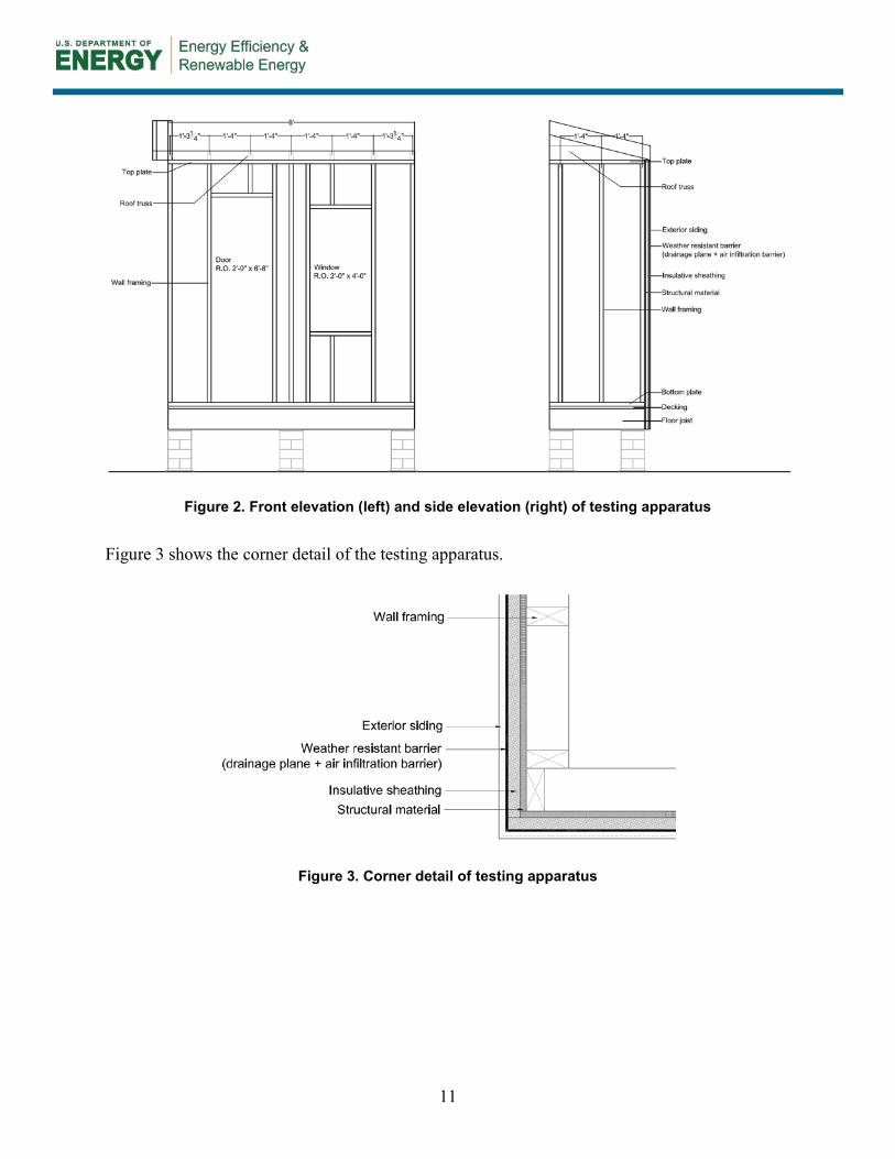
Figure 2 shows the front and side elevations of the testing apparatus framework. The front panel included a door and a window for the process mockups only. Panels used for racking tests did not have any wall openings.
11
Figure 2. Front elevation (left) and side elevation (right) of testing apparatus
Figure 3 shows the corner detail of the testing apparatus.
Figure 3. Corner detail of testing apparatus

12
4 Results: Phase 3—Design Development and Prototyping
Phase 3 of the Advanced Envelope Research focused on the detailed design development and prototyping of wall options based on one of the three core concepts identified in the prior phase of the work. In Phase 2, designs were developed for three high thermal performance envelope technologies: SIPs for walls, stud walls with continuous exterior insulation, and flash and batt wall construction. The “stud walls with continuous exterior insulation” option was selected by the industry-led Steering Committee as the most viable option to move further in the research process.
The objective of this phase was to explore variations on the use of exterior foam insulation and develop wall options based on superior insulation products so that wall performance and functionality are optimized for factory built housing. This information provided the basis for the industry committee to compare and contrast the options to select promising designs for prototyping and testing, also conducted in this phase of research.
4.1 Overview of the Advanced Envelope Research Concept—Stud Walls With Continuous Exterior Insulation
Advanced wall designs were developed with the goal of meeting the prescriptive requirements of the IECC 2012 standards. The industry committee developed a detailed set of wall performance specifications as guidance to the insulation suppliers in recommending design options. These are considered ideal attributes that potentially would be satisfied by a single product incorporated into the overall wall design. Insulation suppliers were encouraged to recommend composite panel concepts based on their proprietary materials that satisfied as many of the conditions as possible. The goal in packing multiple attributes into a single product is to minimize the number of individual products that must be purchased, inventoried, and installed by the plant, saving cost in both handling and main line construction time. The desired attributes are described in Table 1.

13
Table 1. Desired Properties of Advanced Wall Designs With Composite Insulative Sheathing
Properties IECC Climate Zone 5 IECC Climate Zones 6, 7, and 8
Reference Design Design 1 Design 2 Design 3
Required Properties
Insulative Sheathing R-Value
Not applicable R-5 R-10 R-5
Vapor Management7
Class I/II VR on inside.
Preferred: Class I/II insulative sheathing on exterior with Class
III VR on inside. Alternative:8 Class III insulative sheathing on exterior; Class I/II
VR on inside.
Preferred: Class I/II insulative sheathing on exterior with
Class III VR on inside. insulative sheathing on exterior;
Class I/II VR on inside.
Class I/II VR on inside; Insulative sheathing perm
rating at least >1.
Desired Properties
Rain Water Management/
Water Resistive Barrier
(Note: Drainage plane shall be No. 15 asphalt layer compliant with ASTM D 226 Type 1 or other approved
Install drainage plane to the exterior side of
the framing/ insulation. Air space recommended with
drainage plane (Lstiburek 2006).
Preferred: Using the insulative sheathing as a drainage plane (subject to demonstrated long-term durability of the sheathing
or facing material) (Lstiburek 1999).
Alternative: Install drainage plane to the exterior/interior of
the insulative sheathing. Air space recommended with
drainage plane.
Preferred: Using the insulative sheathing as a drainage plane (subject to demonstrated long-term durability of the sheathing
or facing material). Alternative: Install drainage
plane to the exterior/interior of the insulative sheathing. Air
space recommended with drainage plane.
Preferred: Using the insulative sheathing as a
drainage plane (subject to demonstrated long-term
durability of the sheathing or facing material). Alternative: Install
drainage plane to the exterior/interior of the
insulative sheathing. Air space recommended with
drainage plane.
7 Class I VR: 0.1 perms or less (Vapor impermeable); Class II VR: ≤ 1.0 perms and > 0.1 perm (Vapor semi-impermeable); Class III VR: ≤ 10 perms and >n 1.0 perm (Vapor semi-permeable); Not a VR: > 10 perms (Vapor permeable). 8 Mandatory requirement for HUD code homes.

14
Properties IECC Climate Zone 5 IECC Climate Zones 6, 7, and 8
Reference Design Design 1 Design 2 Design 3
water resistive barrier.9)
Air Infiltration Resistance
Install a continuous air infiltration barrier on
the exterior side of the framing/ insulation.
Install a continuous air infiltration barrier on the
exterior/interior of the insulative sheathing.
Install a continuous air infiltration barrier on the
exterior/interior of the insulative sheathing.
Install a continuous air infiltration barrier on the
exterior/interior of the insulative sheathing.
Shear Resistance10, 11 (non-wind zone
areas)
Sheathing on the exterior side with
structural strength of 210 plf minimum.
Sheathing on the exterior side with structural strength of 210
plf minimum.
Sheathing on the exterior side with structural strength of 210
plf minimum.
Sheathing on the exterior side with structural strength of 210 plf
minimum.
9 R703.2 Water-resistive barrier. IRC 2012. 10 Using the gypsum board with a proper adhesive is expected to provide sufficient shear resistance in most areas, at least for homes built under the HUD standards. For modular homes, additional shear resistance may need to be provided by the materials placed outside of the framing, whether as a property of the insulative board (preferred) or through the use of an additional material, such as OSB. 11 Focus on shear strength is a reflection of the industry need to build homes that stand up to racking during transportation.
15
Properties IECC Climate Zone 5 IECC Climate Zones 6, 7, and 8
Reference Design Design 1 Design 2 Design 3
Additional Specifications
Cladding Attachment
Direct cladding attachment to structural sheathing.
Preferred: Direct cladding attachment through
sheathing into the studs using extra-long fasteners
(nails, screws etc.) that can be collated. Certain
fasteners allow up to 4 in. of foam sheathing
thickness. Alternative: Using furring or hat-channel over foam sheathing to support the
siding.
Preferred: Direct cladding attachment through sheathing into the studs using extra-long fasteners (nails, screws etc.) that can be collated. Certain fasteners allow up to 4 in. of
foam sheathing thickness. Alternative: Using furring or
hat-channel over foam sheathing to support the siding.
Preferred: Direct cladding attachment through
sheathing into the studs using extra-long fasteners
(nails, screws etc.) that can be collated.
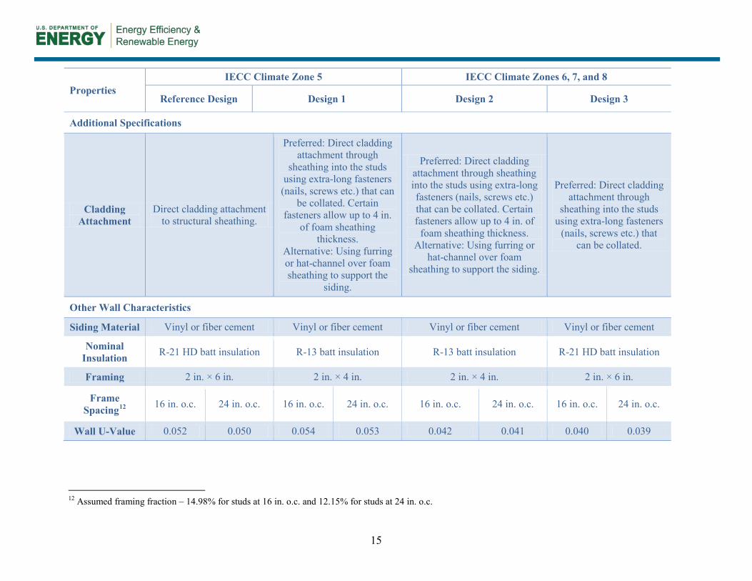
Other Wall Characteristics
Siding Material Vinyl or fiber cement Vinyl or fiber cement Vinyl or fiber cement Vinyl or fiber cement
Nominal Insulation R-21 HD batt insulation R-13 batt insulation R-13 batt insulation R-21 HD batt insulation
Framing 2 in. × 6 in. 2 in. × 4 in. 2 in. × 4 in. 2 in. × 6 in.
Frame Spacing12 16 in. o.c. 24 in. o.c. 16 in. o.c. 24 in. o.c. 16 in. o.c. 24 in. o.c. 16 in. o.c. 24 in. o.c.
Wall U-Value 0.052 0.050 0.054 0.053 0.042 0.041 0.040 0.039
12 Assumed framing fraction – 14.98% for studs at 16 in. o.c. and 12.15% for studs at 24 in. o.c.

16
Figure 4 through Figure 6 below were developed and provided to the participating insulation companies as typical wall sections with the thermal and vapor management properties meeting the IECC 2012 and IRC 2012 requirements, respectively. These figures were intended to be used as a base for developing variations on their current product offerings aimed at performing multiple functions, some of which were specific to the needs of factory homebuilders.
Figure 4 is a typical wall section of a stud wall with exterior insulation meeting the thermal requirements of IECC 2012 climate zone 5, based on the following heat flow targets:
• Prescriptive: R-20 or R-13+5 (wall insulation R-value) or,
• Whole wall performance: 0.057 (wall U-factor).
Figure 4. Stud wall with exterior insulation, Design 1 (climate zone 5)
Figure 5 and Figure 6 are typical wall sections of stud walls with exterior insulation meeting the thermal requirements of IECC 2012 climate zones 6, 7, and 8, based on the following thermal resistance targets:
• Prescriptive: R-20+5 or R-13+10 (wall insulation R-value)
• Whole wall performance: 0.048 (wall U-factor).
Figure 5 is a stud wall with 2 in. × 4 in. framing, R-13 cavity insulation and R-10 exterior insulation. Figure 6 is a similar wall section but with 2 in. × 6 in. framing and R-5 exterior insulation. Cavity insulation is R-20.

17
Figure 5. Stud wall with exterior insulation,
Design 2 (climate zones 6, 7, and 8) Figure 6. Stud wall with exterior insulation,
Design 3 (climate zones 6, 7, and 8)
4.2 Design Development This section describes the various advanced wall solutions developed based on superior insulation products from the participating insulation manufacturers integrated with the provided wall performance specifications.
4.2.1 AFM Corporation 4.2.1.1 Company Background AFM Corporation is the manufacturer of Foam-Control expanded polystyrene (EPS) and R-Control branded SIPs. Foam-Control and R-Control products are available through a network of AFM licensed manufacturing facilities.
4.2.1.2 Concept Overview AFM Corporation proposed advanced wall designs for the factory built housing industry incorporating the use of Foam-Control Nailbrace. The proposed design concept is as follows:
• Concept A: Stud walls with Foam-Control Nailbrace with integrated structural sheathing and weather resistant barrier (WRB).
The following sketches show the Foam-Control Nailbrace wall concepts designed for as per the specifications for Designs 1 and 2 (see Table 1) in climates zones 5, 6, 7, and 8. Similar designs were also developed in response to the requirements for Design 3.

18
Figure 7. Foam-Control Nailbrace Concept A, Design 1 (climate zone 5)
Figure 8. Foam-Control Nailbrace Concept A, Design 2 (climate zones 6, 7, and 8)
4.2.1.3 Design and Materials Foam-Control Nailbrace is a continuous insulation (CI) board applied to the exterior side of framed walls. This product incorporates EPS insulation laminated onto a structural engineered wood sheathing backer. The design incorporates a let-in strip for fastening the siding. This design makes the Foam-Control Nailbrace lighter and easier to handle in a production setting.
The let-in strip in the Foam-Control Nailbrace panel is designed for easy attachment of the siding. Specialty fasteners are required for bracing and to protect against fastener bending and pull-out/pull-through.
4.2.1.3.1 Strengths and Limitations Foam-Control Nailbrace potentially provides the following strengths and limitations:
Strengths
• Braces framed walls and provides structural support
• Provides attachment for exterior cladding
• Pre-installed WRB and air barrier.
Figure 9. Foam-Control Nailbrace with let-in bracing (without WRB)
(Image credit: AFM Corporation, used with permission)
Figure 10. Foam-Control Nailbrace - top view (without WRB)
(Image credit: AFM Corporation, used with permission)
19
Limitations, restrictions on use, general technical challenges
• Alignment of let-in bracing with fastening may be a challenge.
• Cost of composite panel fabrication is likely to be higher than standard sheathing.
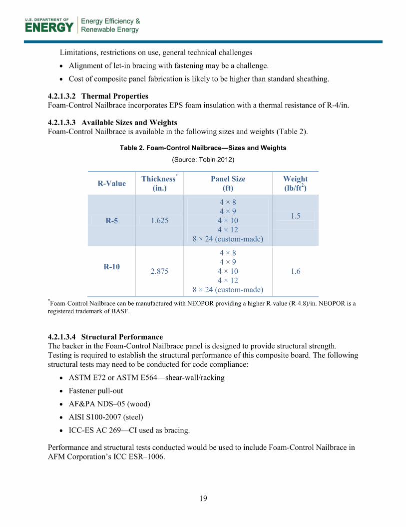
4.2.1.3.2 Thermal Properties Foam-Control Nailbrace incorporates EPS foam insulation with a thermal resistance of R-4/in.
4.2.1.3.3 Available Sizes and Weights Foam-Control Nailbrace is available in the following sizes and weights (Table 2).
Table 2. Foam-Control Nailbrace—Sizes and Weights
(Source: Tobin 2012)
R-Value Thickness*
(in.) Panel Size
(ft) Weight (lb/ft2)
R-5 1.625
4 × 8 4 × 9 4 × 10 4 × 12
8 × 24 (custom-made)
1.5
R-10 2.875
4 × 8 4 × 9 4 × 10 4 × 12
8 × 24 (custom-made)
1.6
*Foam-Control Nailbrace can be manufactured with NEOPOR providing a higher R-value (R-4.8)/in. NEOPOR is a registered trademark of BASF.
4.2.1.3.4 Structural Performance The backer in the Foam-Control Nailbrace panel is designed to provide structural strength. Testing is required to establish the structural performance of this composite board. The following structural tests may need to be conducted for code compliance:
• ASTM E72 or ASTM E564—shear-wall/racking
• Fastener pull-out
• AF&PA NDS–05 (wood)
• AISI S100-2007 (steel)
• ICC-ES AC 269—CI used as bracing.
Performance and structural tests conducted would be used to include Foam-Control Nailbrace in AFM Corporation’s ICC ESR–1006.

20
4.2.1.3.5 Weather Resistive Properties Foam-Control Nailbrace can be manufactured with a factory applied WRB. In this case, edges are required to be taped. Testing is required to establish the WRB and air barrier properties of Nailbrace. The following tests may need to be conducted for code compliance:
• ICC-ES AC 71—foam as a WRB
• ASTM E2357—air infiltration
• ASTM E1677—air barrier performance.
4.2.1.3.6 Vapor Management Properties Foam-Control Nailbrace classifies as a Class III VR.
4.2.2 BASF Corporation 4.2.2.1 Company Background BASF is a chemical company that provides raw materials to fabricators and intermediaries that produce construction-ready products. In the case of NEOPOR—a BASF-produced and patented raw material—NEOPOR rigid thermal insulation is produced in the United States and Canada under a brand marketing agreement by customers of BASF Corporation and BASF Canada, respectively, who convert NEOPOR (the raw material) to NEOPOR foam (rigid thermal insulation).
4.2.2.2 Concept Overview BASF proposed four advanced wall designs incorporating insulation made from its NEOPOR (BASF 2011) rigid thermal insulation product. The four proposed design concepts are as follows:
• Concept A: Stud walls with NEOPOR rigid thermal insulation
• Concept B: Stud walls with oriented strand board (OSB) laminated to NEOPOR rigid thermal insulation
• Concept C: Stud walls with poly-faced NEOPOR rigid thermal insulation
• Concept D: Stud walls with foil-faced NEOPOR rigid thermal insulation.
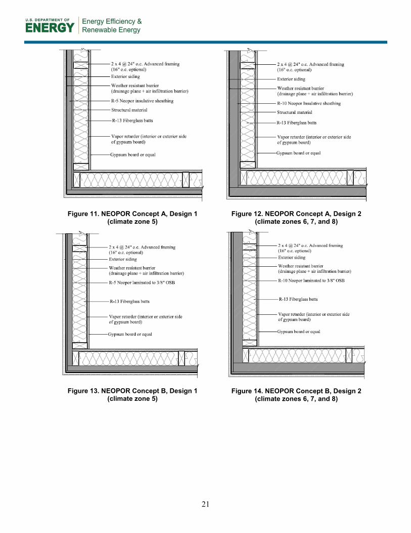
Figure 11 through Figure 14 show wall sections of the four NEOPOR-based concepts in accordance with wall Designs 1 and 2 (see Table 1). Similar designs were also developed in response to specifications for Design 3.
21
Figure 11. NEOPOR Concept A, Design 1 (climate zone 5)
Figure 12. NEOPOR Concept A, Design 2 (climate zones 6, 7, and 8)
Figure 13. NEOPOR Concept B, Design 1 (climate zone 5)
Figure 14. NEOPOR Concept B, Design 2 (climate zones 6, 7, and 8)

22
Figure 15. NEOPOR Concept C, Design 1 (climate zone 5)
Figure 16. NEOPOR Concept C, Design 2 (climate zones 6, 7, and 8)
Figure 17. NEOPOR Concept D, Design 1 (climate zone 5)
Figure 18. NEOPOR Concept D, Design 2 (climate zones 6, 7, and 8)
4.2.2.3 Design and Materials BASF NEOPOR is a unique and patented material used, in its final form, as “rigid thermal insulation” in the construction industry as thermal insulation. This material attributes a distinctive silver-gray color to graphite contained within a polystyrene-based polymer matrix. BASF incorporates high-purity graphite into the polymer matrix. The graphite particles both reflect and absorb radiant energy, thereby increasing the materials insulation capacity, or R-

23
value, while retaining all of the performance benefits inherently found in standard white EPS. NEOPOR rigid thermal insulation can be block molded and wire-cut to form both simple and complex profiles using standard industry equipment and processes.
The physical properties of NEOPOR are outlined in Table 3.
Table 3. NEOPOR—Physical Properties
(Source: BASF 2012, used with permission)
4.2.2.3.1 Strengths and Limitations The strengths and limitations of NEOPOR insulation board are summarized below.
Strengths
• Lightweight
• Easy to cut, shape, install
• GreenGuard Gold certified for Indoor Air Quality by Underwriters Laboratories Environment
• Long-term stable R-value of 4.5–4.6/in., depending upon density
• Dimensionally stable
• Expansion agent has zero ozone depletion potential
• Expansion agent has low global warming potential.

24
Limitations, restrictions on use, general technical challenges
• NEOPOR boards are nonstructural.
4.2.2.3.2 Thermal Properties NEOPOR has an average R-value of 4.8/in. over the temperature range of 23°–75°F and density range of 1.15 pcf (ASTM Type VIII) to 1.80 pcf (ASTM Type IX). The R-value increases as the temperature decreases. The thermal resistance (R-value) properties of NEOPOR are outlined in Table 4.
Table 4. R-Value of NEOPOR Rigid Thermal Insulation
(Source: BASF 2013, used with permission)
NEOPOR 5300 PLUS is a raw material used to produce rigid thermal insulation made of NEOPOR that has the highest R-value of any NEOPOR rigid thermal insulation. Wall systems designed with the R-values for NEOPOR 5300 PLUS should specify “NEOPOR 5300 PLUS” on all system and material specifications.
NEOPOR F 5300 and NEOPOR F 5300 PLUS is a raw material used to produce rigid thermal insulation and uses a polymeric flame retardant instead of HBCD. R-values of NEOPOR at various temperatures and material densities are shown in Figure 19.

25
Figure 19. NEOPOR R-value at 75°F and 40°F
(Source: BASF 2013, used with permission)
4.2.2.3.3 Available Sizes and Weights NEOPOR boards are commonly available in the following sizes and weights. However, NEOPOR is adaptable and can be specified in any thickness and density to achieve specific R-value performance targets.
Table 5. NEOPOR—Sizes and Weights
(Source: Fox 2012)
R-Value Thickness (in.)
Panel Size (ft)
Weight (lb/panel)
R-5 1.125 4 × 8 4
R-10 2.25 4 × 8 N/A
OSB-laminated R-5 1.5 4 × 8 54
OSB-laminated R-10 2.625 4 × 8 N/A

26
4.2.2.3.4 Structural Performance Concepts A, C, and D incorporate NEOPOR boards that are nonstructural. The OSB-laminated NEOPOR board in Concept B provides structural strength. Testing is required to establish the shear resistance of this composite board.
4.2.2.3.5 Weather Resistive Properties Concepts A and B call for the use of a separate WRB to provide water and air resistance13 to the wall system. The OSB-laminated NEOPOR board has the option of a factory-applied WRB (poly- or foil-faced) to act as a water resistive and an air infiltration barrier. Additional testing is required to confirm its performance.
4.2.2.3.6 Vapor Management Properties Depending on density, 1 in. thick NEOPOR has a perm rating of 1.5–3.5 (ng/Pa·s·m2). The classification of the various NEOPOR products based on their permeance is as follows:
• Unfaced foam: Class III VR
• OSB-laminated panel: Class III VR
• Poly- and foil-faced foam: Class II VR.
4.2.3 The Dow Chemical Company 4.2.3.1 Company Background Dow is a global business with a broad range of insulation and other building products for the construction industry.
4.2.3.2 Concept Overview Dow proposed advanced wall designs incorporating its Styrofoam brand extruded polystyrene (XPS) insulation board. Figure 20 is a wall section with Styrofoam XPS designed to meet the 2012 IECC prescriptive code requirements for climate zone 5. Figure 21 shows the wall design meeting code requirements for climate zones 6, 7, and 8 with R-13 in the cavity and R-10 exterior insulation. A similar design was also developed for climates zones 6, 7, and 8 with R-21 in the cavity and R-5 exterior insulation.
13 The OSB or NEOPOR layers can provide air resistance to the wall system if properly taped and sealed or an additional barrier is required.
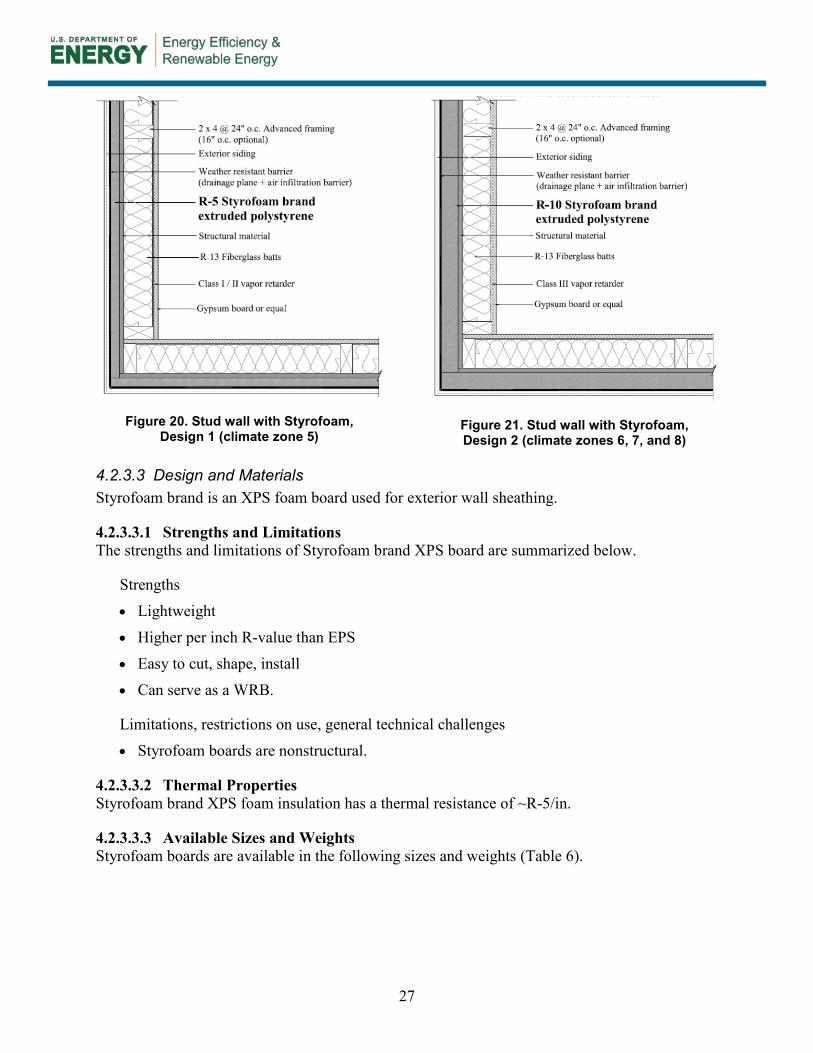
27
Figure 20. Stud wall with Styrofoam, Design 1 (climate zone 5)
Figure 21. Stud wall with Styrofoam, Design 2 (climate zones 6, 7, and 8)
4.2.3.3 Design and Materials Styrofoam brand is an XPS foam board used for exterior wall sheathing.
4.2.3.3.1 Strengths and Limitations The strengths and limitations of Styrofoam brand XPS board are summarized below.
Strengths
• Lightweight
• Higher per inch R-value than EPS
• Easy to cut, shape, install
• Can serve as a WRB.
Limitations, restrictions on use, general technical challenges
• Styrofoam boards are nonstructural.
4.2.3.3.2 Thermal Properties Styrofoam brand XPS foam insulation has a thermal resistance of ~R-5/in.
4.2.3.3.3 Available Sizes and Weights Styrofoam boards are available in the following sizes and weights (Table 6).

28
Table 6. Styrofoam—Sizes and Weights
(Source: Mallon and Lieburn 2012)
R-Value Thickness (in.)
Panel Size (ft)
Weight (lb/panel)
R-5 1 4 × 8 4 × 9 N/A
R-10 2 4 × 8 4 × 9 N/A
4.2.3.3.4 Structural Performance Styrofoam brand foam board is nonstructural.
4.2.3.3.5 Weather Resistive Properties Styrofoam brand foam board is ICC-ES code approved WRB, with tape, sill pans, flashings, spray foam, and foam sealants. It also passes the ASTM E331 wall assembly test for determining resistance to water penetration.
4.2.3.3.6 Vapor Management Properties R-5 Styrofoam brand foam board is a Class III VR, while R-10 board is classified as Class II.
4.2.4 Johns Manville Corporation 4.2.4.1 Company Background Johns Manville (JM) is a manufacturer and marketer of building insulation, commercial roofing, roof insulation, and specialty products for commercial, industrial, and residential applications. JM’s product offerings include formaldehyde-free fiberglass, spray polyurethane foam, polyisocyanurate foam board, and mineral fiber building insulations, commercial roofing membranes and roof insulations, filtration media, and mats and reinforcements.
4.2.4.2 Concept Overview JM proposed the following three wall designs incorporating polyisocyanurate insulation.
• Concept A: Stud walls with ValuTherm sheathing
• Concept B: Stud walls with AP foil-faced sheathing
• Concept C: Stud walls with structural insulated sheathing (SIS).
Figure 22 through Figure 24 show typical wall sections based on JM’s three proposed concepts designed for climate zones 5, 6, 7, and 8.

29
Figure 22. ValuTherm Concept A (climate zones 5, 6, 7, and 8)
Figure 23. AP foil-faced sheathing Concept B (climate zones 5, 6, 7, and 8)
Figure 24. SIS sheathing Concept C (climate zones 5, 6, 7, and 8)
4.2.4.3 Design and Materials Concept A has a polyisocyanurate foam core with fiberglass reinforced paper facers. Concept B has a polyisocyanurate foam core with bi-laminate foil facers. Concept C has a polyisocyanurate foam core with a foil facer on one side and a reinforced/structural facer on the other. The physical properties of the polyisocyanurate insulation products in the three proposed concepts are outlined in Table 7.

30
Table 7. JM Products—Physical Properties
(Sources: JM 2009, 2013a)
Property ValuTherm AP Foil-Faced Sheathing Structural Insulated Sheathing*
R-Value and Thickness
R-5 @ 0.89 in. R-10 @ 1.78 in.
R-5 @ 0.77 in. R-10 @ 1.55 in.
R-5 @ 0.77 in. R-10 @ 1.55 in.
Compressive Strength 16 psi 16 psi 20 psi
Dimensional Stability ≤ ± 2% ≤ ± 0.2% (length and width)
< ± 2% (thickness) ≤ ± 2%
Water Vapor Permeance
1.0 perm-in. (Class II VR)
0.05 perm-in. (Class I VR)
0.05 perm-in. (Class I VR)
Water Absorption ≤ 1.5% 0.3% ≤ 1%
Flame Spread/ Smoke
Developed** N/A ≤ 25 / 450 ≤ 25 / 450
Complies With ASTM C1289-
12, Type II, Class 1, Grade 2
ASTM C1289-12, Type I, Class 1, Grade 1 ICC-ESR 3398
ASTM C1289-12, Type I, Class 1 AC 269/269.2
* The SIS sheathing product is currently under development and its properties are subject to development and/or testing. Values provided in this table are estimates. **Foam core, 4 in. thickness 4.2.4.3.1 Strengths and Limitations The strengths of the polyisocyanurate foam board and limitations of the products for the proposed concepts are listed below:
Strengths
• R-value of the foam is the highest of the products considered in this research phase
• Lightweight
• Easily cut by razor, utility knife, band saw, hot wire, etc.
• Dimensional stability < 0.3%,14 Foam core flame spread/smoke developed indices low compared to standard products
• Concept B product can be used as an air barrier and drainage plane
• Concept C has a structural facer eliminating the need for additional structural support 14 Babineau, F. (November, 2012). Johns Manville Insulating Sheathing Concepts. (PowerPoint slides). Presented at the Building America Expert Meeting, Harrisburg, PA.

31
Limitations, restrictions on use, general technical challenges
Concept A • Requires a separate, exterior water barrier
• No fire certification on the foam board
• No tested structural benefit from ValuTherm.
Concept B • No tested structural benefit from the AP foil-faced sheathing.
Concept C • The SIS sheathing product is under development (not commercially available yet).
Additional tests and code approval are pending.
4.2.4.3.2 Thermal Properties JM’s proposed wall concepts incorporate closed cell polyisocyanurate insulation with a thermal resistance of ~R-6.5/in.
4.2.4.3.3 Available Sizes and Weights Table 8 and Table 9 provide information on available sizes and weights of ValuTherm and AP foil-faced insulation. Since the SIS sheathing product is under development, information on sizes and weights is not available.
Table 8. ValuTherm—Sizes and Weights
(Source: JM 2013b)
R-Value Thickness (in.)
Panel size (ft) Weight
R-5 N/A 4 × 4 N/A
R-10 N/A 4 × 8 N/A
Table 9. AP Foil-Faced Insulation—Sizes and Weights
(Source: JM 2013c)
R-Value Thickness (in.)
Panel size (ft)
Weight (lb/panel)
R-5 N/A 4 × 8 4 × 9
4.1 4.6
R-10 N/A 4 × 8 4 × 9
8.3 9.3

32
4.2.4.3.4 Structural Performance For concepts A and B, the polyisocyanurate foam board is nonstructural. Concept C, SIS sheathing is manufactured with a structural facer and, pursuant to test verification, eliminates the need for additional shear resistance.
4.2.4.3.5 Weather Resistive Properties Concept A requires the use of a separate, exterior WRB. In concepts B and C, the facers function as water resistant and air infiltration barriers when taped and sealed. Table 10 specifies the weather resistive properties of AP foil-faced insulation.
Table 10. AP Foil-Faced Insulation—Weather Resistive Properties
(Source: JM 2013c)
Function Criteria and Results Details
Water Drainage (WRB)*
AC 71: No visible leakage after 2-h test Exova report 12-06-M0306-2
Water Drainage (WRB) AC 71 weathering: No visible
leakage after UV light exposure and accelerated aging
Exova report pending
Air Barrier ASTM E2357: 0.00426 L/sm² (~1% of allowable leakage) Exova report 12-06-M0306-1
Lateral Wind Loads ASTM E1233: resisted -1880 Pa Exova report pending
* WRB, air leakage, and wind loading tested with 3M 8067 flashing tape, Tremco Spectrem I sealant, and 2 in. fastener plates 4.2.4.3.6 Vapor Management Properties All three proposed products have a perm rating of 1.0 or lower, making them Class I and II VRs.
4.2.5 Saint-Gobain/CertainTeed 4.2.5.1 Company Background CertainTeed Corporation is a manufacturer of building materials including roofing, vinyl and fiber cement siding, trim, fence, railing, decking, foundations, insulation, gypsum, ceilings, and pipe products. CertainTeed is a subsidiary of Saint-Gobain.
4.2.5.2 Concept Overview CertainTeed proposed an advanced wall solution incorporating their brand product CertaPro fiberglass insulative sheathing with an optional WRB facing.
Figure 25 and Figure 26 show typical wall sections proposed for climate zones 5, 6, 7, and 8 in response to the specifications in Designs 1 and 2, respectively. A similar design was developed for climate zones 6, 7, and 8 meeting Design 3 requirements.

33
Figure 25. Stud wall with faced CertaPro, Design 1 (climate zone 5)
Figure 26. Stud wall with faced CertaPro, Design 2 (climate zones 6, 7 and 8)
4.2.5.3 Design and Materials The physical properties of unfaced CertaPro fiberglass insulation are outlined in Table 11 below.

34
Table 11. CertaPro—Physical Properties
(Source: CertainTeed 2010)
Property Value
Density (lb/ft3) 4.0
Thermal Resistance (R/in.) 4.3
Water Vapor Absorption (by weight) 2.0%
Compressive Strength (psi @ 10% def) 0.75
Recycled Content Approx. 60%
Flame Spread Index 25
Smoke Developed Index 50
Water Vapor Permeance (perm) >10
Noise Reduction Coefficient 0.8 (1-3/16 in. thick) 1.0 (2⅜ in. thick)
4.2.5.3.1 Strengths and Limitations The strengths and limitations of CertaPro fiberglass insulation are summarized below.
Strengths
• Higher R-value per inch than standard EPS
• Provides high sound absorption
• Contains approximately 60% recycled content
• Offered in a variety of stiffness properties from flexible to rigid and all can be easily cut, handled, fabricated, and installed
• Resists mold and mildew and will not rot or deteriorate
• Has superior fire performance (25/50).
Limitations, restrictions on use, general technical challenges
• CertaPro boards are nonstructural.
4.2.5.3.2 Thermal Properties CertaPro fiberglass insulation board has a thermal resistance of R-4.4/in.
4.2.5.3.3 Available Sizes and Weights CertaPro insulation is available in the following sizes and weights.

35
Table 12. CertaPro—Sizes and Weights
(Source: CertainTeed 2010)
R-Value Thickness (in.)
Panel Size (ft)
Weight (lb/ft2)
R-5 1-3/16 4 × 8 0.39
R-10 2⅜ 4 × 8 0.78
4.2.5.3.4 Structural Performance CertaPro fiberglass insulation board is nonstructural.
4.2.5.3.5 Weather Resistive Properties CertaPro insulation is available with an optional WRB facing. The WRB facing with taped seams qualifies as a water resistive and air barrier.
4.2.5.3.6 Vapor Management Properties The WRB facing on CertaPro insulation classifies as a Class III VR.
4.3 Production Analysis This section addresses production impact of the designs. The team conducted an independent assessment of the process by which the options would be integrated into the manufacturing fabric, considering the following factors:
• Safety: risk of injury when performing the operations, using the equipment and handling the material
• Quality: likelihood of scrap, rework, delays in the factory and, worst of all, service calls
• Labor: added work content for sheathing activity
• Flow: increased risk of line disruptions, added workstations and subsequent activities pushed down-line, etc.
The impact of the proposed options on standard production process is graphically presented below. The steps involved in standard wall production are listed to the left. An “X” indicates that the product has a measurable impact on production. The relative size of the impact is suggested by color coding. The colors are in order of greatest to least impact: red, orange, and yellow.
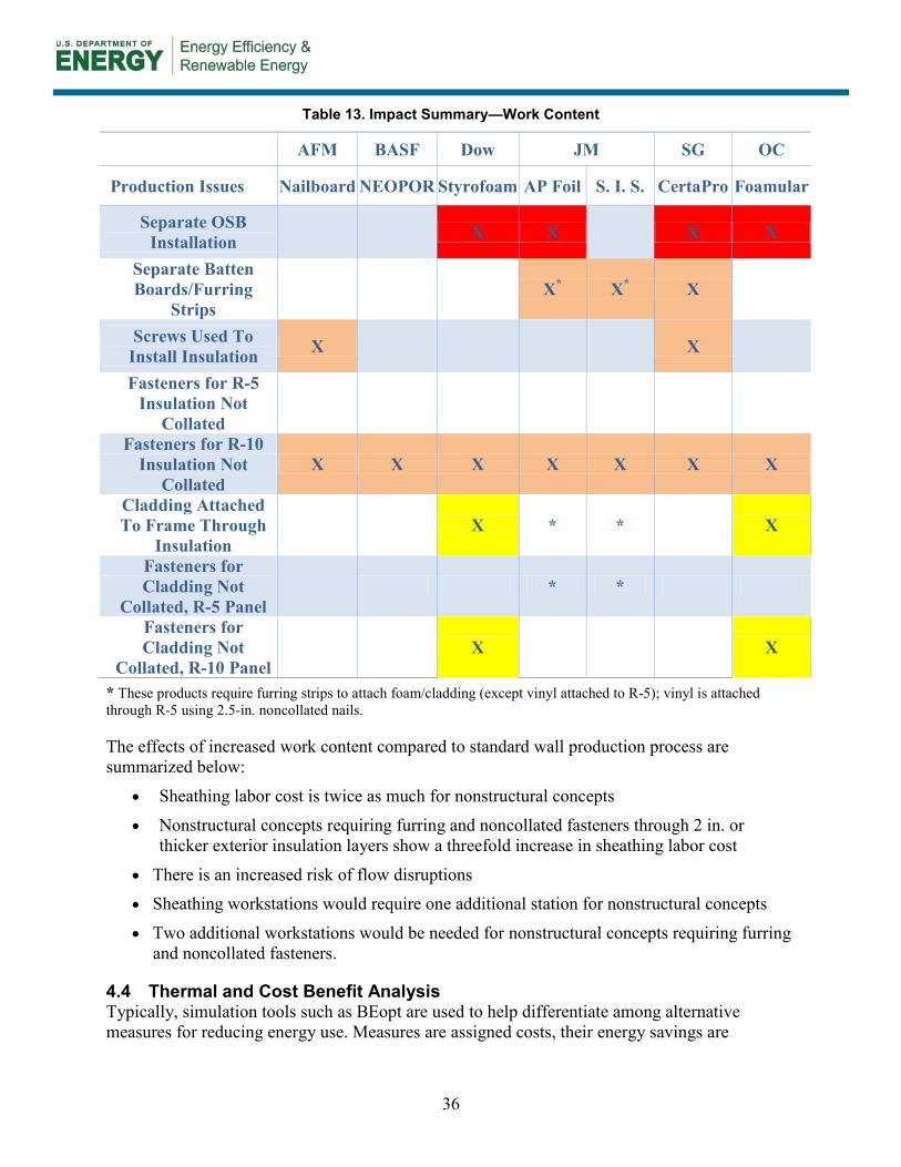
36
Table 13. Impact Summary—Work Content
AFM BASF Dow JM SG OC
Production Issues Nailboard NEOPOR Styrofoam AP Foil S. I. S. CertaPro Foamular
Separate OSB Installation X X X X
Separate Batten Boards/Furring
Strips X* X* X
Screws Used To Install Insulation X X Fasteners for R-5
Insulation Not Collated
Fasteners for R-10 Insulation Not
Collated X X X X X X X
Cladding Attached To Frame Through
Insulation X * * X
Fasteners for Cladding Not
Collated, R-5 Panel * *
Fasteners for Cladding Not
Collated, R-10 Panel X X
* These products require furring strips to attach foam/cladding (except vinyl attached to R-5); vinyl is attached through R-5 using 2.5-in. noncollated nails.
The effects of increased work content compared to standard wall production process are summarized below:
• Sheathing labor cost is twice as much for nonstructural concepts
• Nonstructural concepts requiring furring and noncollated fasteners through 2 in. or thicker exterior insulation layers show a threefold increase in sheathing labor cost
• There is an increased risk of flow disruptions • Sheathing workstations would require one additional station for nonstructural concepts
• Two additional workstations would be needed for nonstructural concepts requiring furring and noncollated fasteners.
4.4 Thermal and Cost Benefit Analysis Typically, simulation tools such as BEopt are used to help differentiate among alternative measures for reducing energy use. Measures are assigned costs, their energy savings are

37
estimated and then are ranked in terms of cost effectiveness. This approach allows different types of measures (impacting different end uses, with varying impacts on energy use and with different costs) to be readily compared and combined into cost-optimized whole building solutions. However, the team was operating within a different context for cost optimization where the end result is fixed (in this case, wall R-value to be achieved using insulative sheathing). The questions revert to:
• What is the least cost way to reach the specified R-value?
• What should the target cost be to achieve a designated economic return, such as payback or return on investment?
The first question is readily answered by comparing costs of alternatives: in this case, more than 50 options for using R-5 and R-10 insulative sheathing developed in partnership with six original equipment manufacturer (OEM) insulation suppliers. The task is simply to determine which option(s) is the least costly; material, labor, and related costs considered. The second question—what should the cost be to satisfy preset financial criteria—is more salient. Different parties may have divergent views on what qualifies as cost effective. To begin to place bounds on the answer, an analysis was conducted for representative locations in IECC regions 5, 6, and 7 (all are in zone 3 of the HUD thermal standards). Energy savings was projected using BEopt and maximum measure costs were calculated that satisfy three economic metrics: simple pay back (7-year time horizon); return on investment (target 10%); and net zero cash flow (first year). The results are shown on Table 14.
Table 14. Allowable Cost of Insulative Sheathing To Qualify as Cost Effective
Location IECC Region
Energy Savings ($/ft2/yr)
Maximum Allowable Cost ($/ft2)
Simple Payback
(7-yr)
Return on Investment
(10%)
Net Zero Cash Flow
(year 1)
Lancaster, Pennsylvania 5 $0.114 $0.80 $1.14 $1.53
Great Falls, Montana 6 $0.157 $1.10 $1.57 $2.11
International Falls, Minnesota 7 $0.189 $1.32 $1.89 $2.54
For these three methods of measuring cost-benefit, the threshold maximum cost when adding insulative sheathing is $0.80–$2.54 (a huge range reflecting, in part, climate variations, energy costs, and differences in requirements by climate region, among other factors). To be deemed cost effective, the incremental cost of the measure will need to be equal to or below these values; that is, if the cost of the measure is higher than this range it can be broadly deemed not to be cost effective. (The three methods for conducting cost-benefit analysis are intended to be illustrative, not exhaustive. For example, using a life cycle cost optimization criterion would likely result in different [higher?] allowable measure costs, as would modifying the assumptions used with any
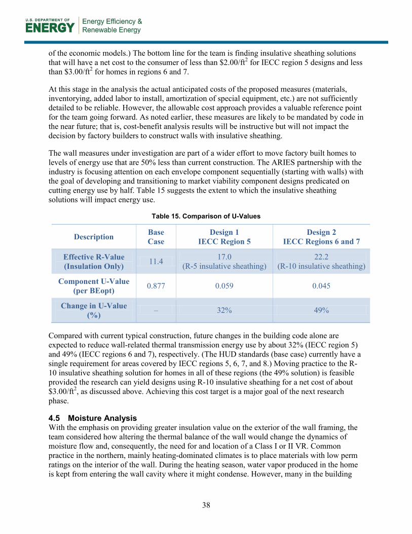
38
of the economic models.) The bottom line for the team is finding insulative sheathing solutions that will have a net cost to the consumer of less than $2.00/ft2 for IECC region 5 designs and less than $3.00/ft2 for homes in regions 6 and 7.
At this stage in the analysis the actual anticipated costs of the proposed measures (materials, inventorying, added labor to install, amortization of special equipment, etc.) are not sufficiently detailed to be reliable. However, the allowable cost approach provides a valuable reference point for the team going forward. As noted earlier, these measures are likely to be mandated by code in the near future; that is, cost-benefit analysis results will be instructive but will not impact the decision by factory builders to construct walls with insulative sheathing.
The wall measures under investigation are part of a wider effort to move factory built homes to levels of energy use that are 50% less than current construction. The ARIES partnership with the industry is focusing attention on each envelope component sequentially (starting with walls) with the goal of developing and transitioning to market viability component designs predicated on cutting energy use by half. Table 15 suggests the extent to which the insulative sheathing solutions will impact energy use.
Table 15. Comparison of U-Values
Description Base Case
Design 1 IECC Region 5
Design 2 IECC Regions 6 and 7
Effective R-Value (Insulation Only) 11.4 17.0
(R-5 insulative sheathing) 22.2
(R-10 insulative sheathing)
Component U-Value (per BEopt) 0.877 0.059 0.045
Change in U-Value (%) – 32% 49%
Compared with current typical construction, future changes in the building code alone are expected to reduce wall-related thermal transmission energy use by about 32% (IECC region 5) and 49% (IECC regions 6 and 7), respectively. (The HUD standards (base case) currently have a single requirement for areas covered by IECC regions 5, 6, 7, and 8.) Moving practice to the R-10 insulative sheathing solution for homes in all of these regions (the 49% solution) is feasible provided the research can yield designs using R-10 insulative sheathing for a net cost of about $3.00/ft2, as discussed above. Achieving this cost target is a major goal of the next research phase.
4.5 Moisture Analysis With the emphasis on providing greater insulation value on the exterior of the wall framing, the team considered how altering the thermal balance of the wall would change the dynamics of moisture flow and, consequently, the need for and location of a Class I or II VR. Common practice in the northern, mainly heating-dominated climates is to place materials with low perm ratings on the interior of the wall. During the heating season, water vapor produced in the home is kept from entering the wall cavity where it might condense. However, many in the building
39
science community contend that using a Class III VR on the interior is appropriate when applying insulative sheathing to the exterior of the wall. This view is codified in Section R702.7.1 of the 2012 IRC. 15, 16
In setting desired wall properties for the design development work, the team provided for three ways to approach moisture control: (1) using a Class I or II VR on the exterior of the wall; (2) applying a Class I or II material on the interior of the wall (as traditionally built); or (3) having no Class I or II VR anywhere in the wall. Preliminary WUFI analysis was conducted on several of the designs. Two cases illustrate the results.
Figure 27 shows a cross section of a wall with 2 in. of XPS insulation (blue bar). The wall, from exterior to interior, has exterior vinyl siding, XPS, OSB, framing with batt insulation, and gypsum board finished with two coats of latex paint. The insulation has a Class II VR rating; all other materials are rated Class III or are vapor permeable. The graph below charts the relative humidity (RH) and temperature at the inside surface of the OSB, the place in the wall experiencing the highest RH readings. As can be seen, RH, an indicator of the propensity of the wall to experience conditions that might be conducive to mold growth and condensation, peaks in the shoulder months. However, the conditions rarely exceed 95% RH for sustained periods, suggesting that this wall is unlikely to experience moisture-related failures.
WUFI results for the 6 in. frame wall with R-5 insulative sheathing show a similar pattern with lower RH values (see Figure 28). This wall uses the same materials, although a Class II VR is applied between the framing and gypsum board. It is likely that removing the VR would elevate RH levels but not to a degree that would cause concern. This configuration will be explored further in subsequent phases of the research.
15 During a project Expert Meeting, Joe Lstiburek of Building Science Corporation discussed the testing and research conducted to support this approach and the genesis of the IRC requirement. 16 It should be noted that the moisture analysis considers vapor flow and ignores air transported moisture. Airflow and air leakage typically are much more significant to moisture transport than vapor diffusion.

40
Figure 27. WUFI results for wall with R-10 (2 in. XPS) insulation in International Falls
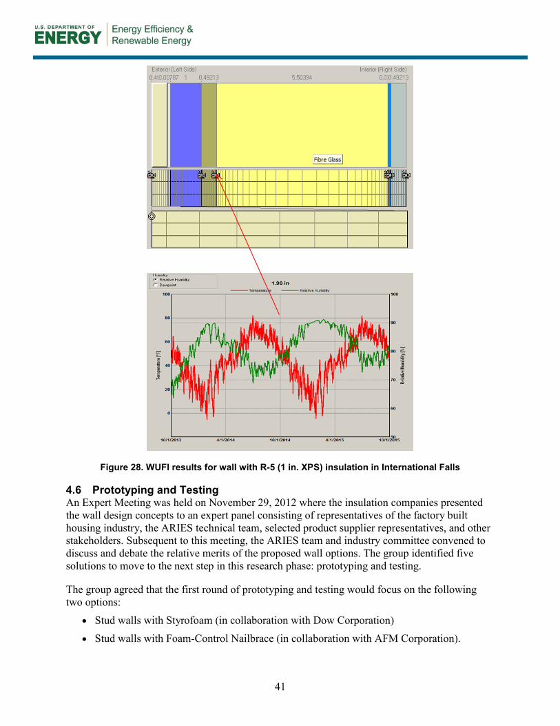
41
Figure 28. WUFI results for wall with R-5 (1 in. XPS) insulation in International Falls
4.6 Prototyping and Testing An Expert Meeting was held on November 29, 2012 where the insulation companies presented the wall design concepts to an expert panel consisting of representatives of the factory built housing industry, the ARIES technical team, selected product supplier representatives, and other stakeholders. Subsequent to this meeting, the ARIES team and industry committee convened to discuss and debate the relative merits of the proposed wall options. The group identified five solutions to move to the next step in this research phase: prototyping and testing.
The group agreed that the first round of prototyping and testing would focus on the following two options:
• Stud walls with Styrofoam (in collaboration with Dow Corporation)
• Stud walls with Foam-Control Nailbrace (in collaboration with AFM Corporation).
42
The insulation type for both products is polystyrene; EPS (Foam-Control Nailbrace) and XPS (Styrofoam) in two thicknesses each, to achieve R-5 and R-10.
The two-day meeting consisted of the following evaluations:
• Racking test demonstrating structural compliance with ASTM E72-80 or ASTM E564 required for compliance under the HUD standards.
• Wall panel mockup for assessing fabrication sequence, building details, and related issues.
• Window construction assessment, particularly with regard to structural support of the window when perched over the exterior insulation.
4.6.1 Location and Participants Prototyping and testing of the selected solutions was conducted on February 6 and 7, 2013 at a participating partner manufacturing plant—Fleetwood Homes, Inc.— in Riverside, California. Fleetwood Homes is a subsidiary of Cavco Industries.
The meeting was attended by the project steering committee, the insulation manufacturers involved in the design development of the selected wall options, and the ARIES technical team.
4.6.2 Racking Tests Racking tests were conducted on the Dow and AFM products in a few different configurations. The purpose of the racking tests was to develop a ballpark estimate of racking strength, a preliminary figure to guide future analysis and design direction. A single test was performed for each wall following the ASTM E564 protocol with regard to load application and load cycling (typically the testing protocol involves the averaging of results from three samples).
Only walls with R-5 were tested, the most likely insulation level to be used in the short term. For the testing of the wall with Dow Styrofoam, the team speculated that the siding and gypsum board might impact the ultimate shear load. Four tests were conducted, two with each siding material representative of the typical products used by the factory building industry that were expected to provide some racking strength (vinyl was not tested). The siding materials were each tested with and without interior gypsum board.17 Table 16 lists the variations of wall type combinations with Styrofoam that were subject to the ASTM E72-80/E564 racking test.18 See Appendices A and B for details on the tests and equipment and material needs.
17 Testing was done on wall assemblies without gypsum board to compare results with assemblies that included gypsum board. As noted earlier, gypsum board with the proper adhesive may provide sufficient shear resistance but only in certain areas. Additional shear resistance may be needed in higher wind zones. 18 The tests followed the procedures described in the ASTM protocol except only a single sample of each wall was tested. The full qualifying protocol requires testing three samples of each wall and averaging the results.

43
Table 16. Racking Tests—Stud Walls With Styrofoam
Case No. R-Value (thickness) Siding Gypsum Board
Present Ultimate Load
(lb)
RD1 (a) R-5 (1 in.) LP SmartSide Yes 6,701
RD1 (b) R-5 (1 in.) LP SmartSide No 5,842
RD2 (a) R-5 (1 in.) Cempanel Yes 4,523
RD2 (b) R-5 (1 in.) Cempanel No 6,200
Table 17 lists the racking test iterations for wall options based on the “stud walls with Foam-Control Nailbrace” design.
Table 17. Racking Tests—Stud Walls With Foam-Control Nailbrace
Case No. R-Value (thickness) Siding Gypsum
Board Present Ultimate Load
(lb)
RA1 (a) R-5 (1⅝ in.) LP SmartSide Yes 7,154
RA1 (b) R-5 (1⅝ in.) LP SmartSide No Excessive deflection
4.6.3 Process Mockup Evaluation and Observation The purpose of the partial wall mockups was to consider issues that will arise in a plant setting when the materials, associated with the Dow and AFM design concepts move into production. Again, this was a limited evaluation intended to reveal general issues of material assembly and production friendliness. The mockups were intended to expose major stumbling blocks to be addressed by future research. The design of the mockups followed from discussions with the industry panel and reflected, in part, their preferences with regard to combinations of materials. Table 18 lists the different wall type combinations with Styrofoam that were mocked up.
Table 18. Process Mockups—Stud Walls With Styrofoam
Case No. R-Value (thickness)
Separate Structural Sheathing Present Siding Window Framing
Detail No.*
MD1 R-5 (1 in.) No LP SmartSide 1
MD2 R-5 (1 in.) No LP SmartSide 3
MD3 R-5 (1 in.) Yes (OSB) Cempanel 2
MD4 R-10 (2 in.) No Cempanel 1 *See Section 4.6.4 for a description of the window framing details.

44
Table 19 lists the process mockup iterations for wall options based on the “stud walls with Foam-Control Nailbrace” design.
Table 19. Process Mockups—Stud Walls With Foam-Control Nailbrace
Case No. R-Value (thickness)
Separate Structural Sheathing Present Siding Window Framing
Detail No.*
MA1 R-5 (1⅝ in.) No LP SmartSide 1
MA2 R-5 (1⅝ in.) No Vinyl 3
MA3 R-5 (1⅝ in.) No Vinyl 2
*See Section 4.6.4 for a description of the window framing details.
4.6.4 Window Construction Assessment One of the major issues of concern is the durability of the window attachment to the structural frame when the window partially or entirely sits over the exterior insulation. The group agreed to consider three methods of detailing the window frame for comparative analysis in Riverside: having the window sit on the foam insulation and secured to the frame with nails, creating a buck lumber frame around the window, and inserting a thin profile rail or clip that attaches to the frame and supports the window. The three options are shown in Figure 29 through Figure 31 below.
Figure 29 (Detail 1) shows a simple installation option where the window frame bearing rests on the foam.19
Figure 29. Detail 1—Window frame bearing on foam
Figure 30 is a wall opening detail with a protruding frame designed to provide the window with solid wood bearing. This design also includes a foam spacer that reduces thermal bridging.
19 Placing the flange over the siding is standard industry practice.

45
Figure 30. Detail 2—Window framing with buck lumber
Figure 31 shows detail of a window frame installation option with a metal L-section providing a rigid surface to support the window.
Figure 31. Detail 3—Window framing with metal L-section

46
5 Discussion
5.1 Stud Walls With Styrofoam In general, the use of Dow Styrofoam brand XPS insulation board and related products offered a solution that is fairly well-resolved with regard to construction detailing but requires further development for factory use. For the most part, the tongue and groove material fit together with relative ease, presenting no apparent thermal breaks—realizing the primary goal of substantially increasing the thermal integrity of the wall. The relative high density and compression strength of the foam may be sufficient to allow the window to bear partially or entirely on the foam, enabling the use of fairly simple windows and door framing details. Visually, the foam coverage gave the impression of a CI layer that is durable, virtually eliminates thermal bridging, and can be installed in the plant with little training. Application of tape to the joints enabled the material to also serve as the air and water resistive barrier, providing potential cost savings. Easily installed plastic window pan flashing is an appealing part of the overall package.
General observations and items that require further analysis and development are described below:
5.1.1 Construction Detailing The foam may require additional blocking to provide adequate nail base at vertical transitions of materials. The goal is to develop a corner framing detail that accommodates varying foam thicknesses without creating a wood thermal bridge while providing a nailing surface for the corner molding and siding edge.

47
The detail at the bottom of the wall needs to be considered and resolved. The group discussed common finish options, including adding a finish blocking strip and/or an insect screen or leaving the foam exposed.
5.1.2 Installing Windows and Doors Cutting out openings with a router creates debris that must be cleaned up. The proper tool was not available for the mockup. The routing bit would need to be sufficiently long to allow the router lead edge to rest on and be guided by the framed opening. Using a routing tool is a relatively fast process; cutting openings with reciprocating saws took longer and was awkward, less accurate, and created more debris. Even where the routing was imprecise, the exposed area was small and easily patched. Getting the proper routing tool is crucial. The preferred tool for this application would be a hot wire or hot knife.

48
When 1 in. of foam sheathing is added to a 2 × 4 frame wall assembly, standard 4-6/16 in. depth door jambs will need a 1 in. extension applied to the interior to provide a flush surface for the interior trim attachment. Standard hinges typically allow a 1 in. extension to the interior without limiting a full 180° door swing. When 2 in. foam sheathing is added to a 2 × 4 frame wall assembly, standard 6-9/16 in. jambs can be used with no additional steps.
How the window is supported when cantilevered over the foam could have a significant influence on the framing details. Kinro (the HUD industry’s major window supplier) volunteered to conduct tests of windows on foam with various foam densities, bearing and siding materials. Testing will focus on the robustness of the fastening under cyclical loading.
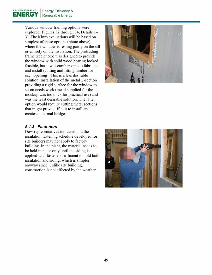
49
Various window framing options were explored (Figures 32 through 34, Details 1–3). The Kinro evaluations will be based on simplest of these options (photo above) where the window is resting partly on the sill or entirely on the insulation. The protruding frame (see photo) was designed to provide the window with solid wood bearing looked feasible, but it was cumbersome to fabricate and install (cutting and fitting lumber for each opening). This is a less desirable solution. Installation of the metal L-section providing a rigid surface for the window to sit on needs work (metal supplied for the mockup was too thick for practical use) and was the least desirable solution. The latter option would require cutting metal sections that might prove difficult to install and creates a thermal bridge.
5.1.3 Fasteners Dow representatives indicated that the insulation fastening schedule developed for site builders may not apply to factory building. In the plant, the material needs to be held in place only until the siding is applied with fasteners sufficient to hold both insulation and siding, which is simpler anyway since, unlike site building, construction is not affected by the weather.
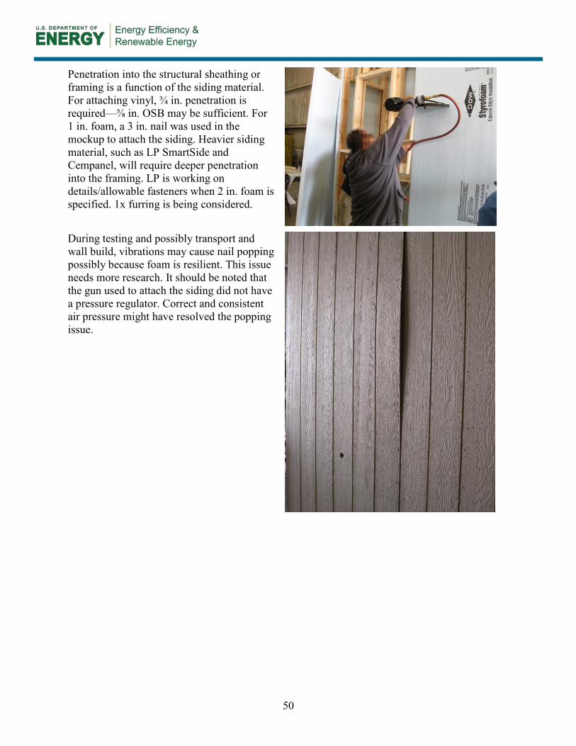
50
Penetration into the structural sheathing or framing is a function of the siding material. For attaching vinyl, ¾ in. penetration is required—⅝ in. OSB may be sufficient. For 1 in. foam, a 3 in. nail was used in the mockup to attach the siding. Heavier siding material, such as LP SmartSide and Cempanel, will require deeper penetration into the framing. LP is working on details/allowable fasteners when 2 in. foam is specified. 1x furring is being considered.
During testing and possibly transport and wall build, vibrations may cause nail popping possibly because foam is resilient. This issue needs more research. It should be noted that the gun used to attach the siding did not have a pressure regulator. Correct and consistent air pressure might have resolved the popping issue.

51
Siding was dimpled when fastening guns were used to apply siding over foam. This can be addressed by using adjustable pressure guns. Having to adjust the gun pressure on the line for different products was cited as a possible drawback.
5.1.4 Assembly/Production Foam boards were easy to position and tack in place. Also it was easy to rout out openings.

52
Tape was applied to seal joints, enabling the wall to act as an air and moisture barrier. The tape was relatively easy to apply to the mockup. This might be a bit harder on the line since the tape extends to the top of the wall. However, applying tape was considered far easier and less work than adding a separate air barrier (e.g., Tyvek).
Securing the siding through foam is more challenging since the fasteners need to travel farther (through the insulation) before hitting the studs. Finding studs could be expedited by printing stud lines on the insulation board.
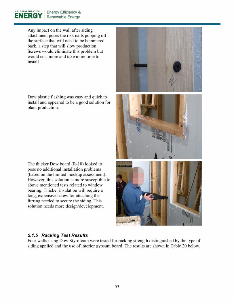
53
Any impact on the wall after siding attachment poses the risk nails popping off the surface that will need to be hammered back, a step that will slow production. Screws would eliminate this problem but would cost more and take more time to install.
Dow plastic flashing was easy and quick to install and appeared to be a good solution for plant production.
The thicker Dow board (R-10) looked to pose no additional installation problems (based on the limited mockup assessment). However, this solution is more susceptible to above mentioned tests related to window bearing. Thicker insulation will require a long, expensive screw for attaching the furring needed to secure the siding. This solution needs more design/development.
5.1.5 Racking Test Results Four walls using Dow Styrofoam were tested for racking strength distinguished by the type of siding applied and the use of interior gypsum board. The results are shown in Table 20 below.

54
Table 20. Racking Test Results—Stud Walls With Styrofoam
Case No. R-Value (thickness) Siding Gypsum Board
Present Ultimate Load
lb plf*
RD1 (a) R-5 (1 in.) LP SmartSide Yes 6,701 335
RD1 (b) R-5 (1 in.) LP SmartSide No 5,842 292
RD2 (a) R-5 (1 in.) Cempanel Yes 4,523 226
RD2 (b) R-5 (1 in.) Cempanel No 6,200 310
* Assumes a 2.5 safety factor
Results and examination of the panels after testing suggest the following:
All achieved the target 210 plf, including two walls built without interior gypsum. The siding (LP SmartSide and Cempanel) likely contributed some shear value.

55
The ultimate load for RD2(a) was lower than RD2(b), despite the addition of gypsum board. This is a counterintuitive result and suggests the preliminary nature of these tests. The low strength of RD2(a) is an outlier and suggests that this test should be revisited.
The RD1 tests indicated that the addition of gypsum adds to the shear strength, as expected.
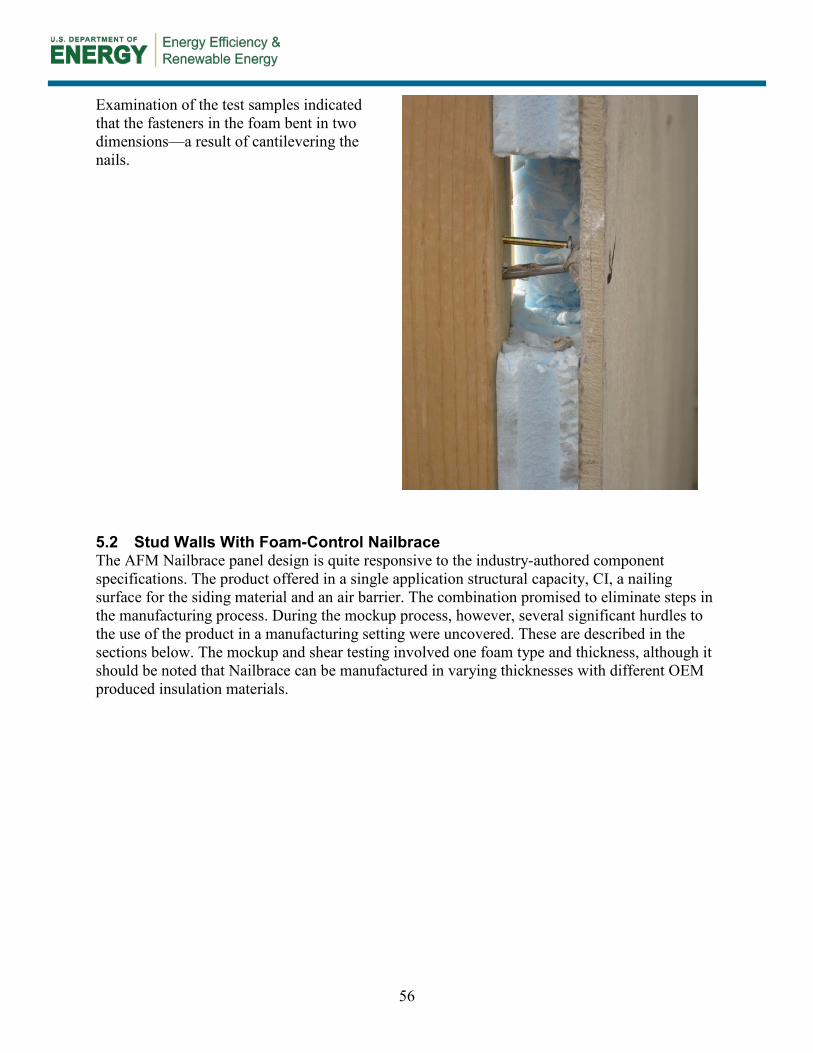
56
Examination of the test samples indicated that the fasteners in the foam bent in two dimensions—a result of cantilevering the nails.
5.2 Stud Walls With Foam-Control Nailbrace The AFM Nailbrace panel design is quite responsive to the industry-authored component specifications. The product offered in a single application structural capacity, CI, a nailing surface for the siding material and an air barrier. The combination promised to eliminate steps in the manufacturing process. During the mockup process, however, several significant hurdles to the use of the product in a manufacturing setting were uncovered. These are described in the sections below. The mockup and shear testing involved one foam type and thickness, although it should be noted that Nailbrace can be manufactured in varying thicknesses with different OEM produced insulation materials.

57
5.2.1 Construction Detailing The use of any foam product creates issues with detailing corners particularly evident when vinyl siding is used. The goal is to develop a corner framing detail that accommodates varying foam thicknesses without creating a wood thermal bridge while providing a nailing surface for the corner molding and siding edge.
The detail at the bottom of the wall needs to be considered and resolved. The group discussed common finish options including adding a finish blocking strip and/or an insect screen or leaving the foam exposed. The manufacturer noted that they have details to finish the base of the Nailbrace to protect against intrusion from rodents and insects.

58
The pattern of inset nailing strips is confined to verticals spaced 16 in. oc (closer for the edge strips). This raised two concerns. First, the lack of a nailing surface at the top and bottom plates meant that no fasteners were at the top and bottom of the panel (sacrificing potential shear resistance) or requiring that screws be used in these areas will have negative cost consequences. These limitations were also an issue at seams that do not fall on the 16 in. grid, such as at openings.
Nailbrace can perform its bracing benefit only if attached with screws; nails are not sufficient. Screws are applied through the nailstrips and along the top and bottom of the Nailbrace into the foam, driven so that the screw heads finish snug against the nail strips and at the foam just below the surface of the foam face. The technique of screwing through the foam works at terminations around all openings as well.
5.2.2 Installing Windows and Doors Cutting out openings with a router creates debris that must be cleaned up. The proper tool was not available for the mockup. The routing bit would need to be sufficiently long to allow the router lead edge to rest on and be guided by the framed opening. Using a routing tool is a relatively fast process; cutting openings with a Sawzall took longer and was awkward, less accurate, and created more debris. Even where the routing was imprecise, the exposed area was small and easily patched. Getting the proper routing tool that can cut structural sheathing and foam is crucial.

59
Detailing of door needs consideration to make sure hinge action (door swing) is not constrained by the foam thickness.
How the window is supported when cantilevered over the foam could have a significant influence on the framing details. Kinro (the HUD industry’s major window supplier) volunteered to conduct tests of windows on foam with various foam densities, bearing and siding materials. Testing will focus on the robustness of the fastening under cyclical loading.
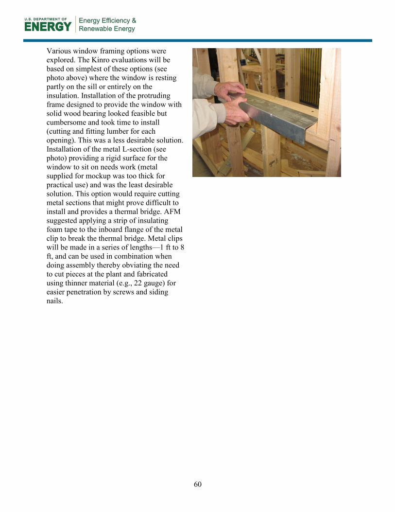
60
Various window framing options were explored. The Kinro evaluations will be based on simplest of these options (see photo above) where the window is resting partly on the sill or entirely on the insulation. Installation of the protruding frame designed to provide the window with solid wood bearing looked feasible but cumbersome and took time to install (cutting and fitting lumber for each opening). This was a less desirable solution. Installation of the metal L-section (see photo) providing a rigid surface for the window to sit on needs work (metal supplied for mockup was too thick for practical use) and was the least desirable solution. This option would require cutting metal sections that might prove difficult to install and provides a thermal bridge. AFM suggested applying a strip of insulating foam tape to the inboard flange of the metal clip to break the thermal bridge. Metal clips will be made in a series of lengths—1 ft to 8 ft, and can be used in combination when doing assembly thereby obviating the need to cut pieces at the plant and fabricated using thinner material (e.g., 22 gauge) for easier penetration by screws and siding nails.

61
Routing of openings was done from the inside using a Sawzall. This sped up the process—the harder surface to cut (structural sheathing) is in contact with the stud that serves as a guide. Cutting from the inside may be easier to do on a production basis.
5.2.3 Fasteners In general, it appeared that nails won’t provide sufficient fastening strength. This may be because the strips are embedded in the foam which has a tendency to flex pulling the nails out of the framing. If screws are required in order for the fastener to grip the OSB/framing, the material cost and labor required for panel installation will increase, potentially significantly.

62
Use of screws is more likely to be justified if used in limited application (e.g., end walls) and if those shear walls can develop sufficient strength. Unfortunately, collated screws were not available for the tests but the plant will consider running an additional racking test with screws, including fasteners along the top and bottom plates.
The LP representative indicated that the OSB would not count toward the required depth of nail penetration for the Smart Side product.

63
The thickness of the insulation made it more difficult to hit the studs with the fasteners, a limitation of sheathing materials in general.
Siding was dimpled when fastening guns were used to apply siding over foam. This can be addressed by using adjustable pressure guns. Having to adjust the gun pressure on the line for different products was cited as a possible drawback. This drawback might be addressed by the use of different fasteners and tools.
It was evident that the use of a new material such as foam sheathing will require worker training, careful execution and proper tools.

64
5.2.4 Assembly/Production In a single product, Nailbrace serves the functions of several different products currently installed in multiple layers over the wall (structural sheathing, insulation, WRB, furring for siding application). This is potentially a significant cost saver in terms of time, possibly material, and inventorying costs, and could increase plant throughput.
Except for creating a starter hole, cutting the panels for openings posed no extraordinary challenges. A proper routing tool (deep enough for the panel and capable of cutting OSB and foam at the same time) is essential for this option to work.

65
The panel weights make having two workers essential to installation on the line, but this is probably similar to (no more difficult than) installing structural sheathing. The weight of the foam and nailstrips adds less than 10 lb to an OSB sheet that weighs 45 lb.
5.2.4.1 Racking Test Results Two walls using AFM Nailbrace were tested for racking strength one with and the other without interior gypsum board. It should be noted that Nailbrace was not fastened at the top and bottom plates for these tests.20 AFM noted that attaching Nailbrace with screws will substantially improve the load capacity of the wall. The results are shown on Table 21 below.
Table 21. Racking Test Results—Stud Walls With Foam-Control Nailbrace
Case No. R-value (thickness) Siding Gypsum Board
Present Ultimate Load
lb plf*
RA1 (a) R-5 (1⅝ in.) LP SmartSide Yes 7,154 357
RA1 (b) R-5 (1⅝ in.) LP SmartSide No Excessive deflection na
* Assumes a 2.5 safety factor.
20 Absence of let-in bracing at the top and bottom was discussed after the tests but not pursued since this option was dropped from further consideration.
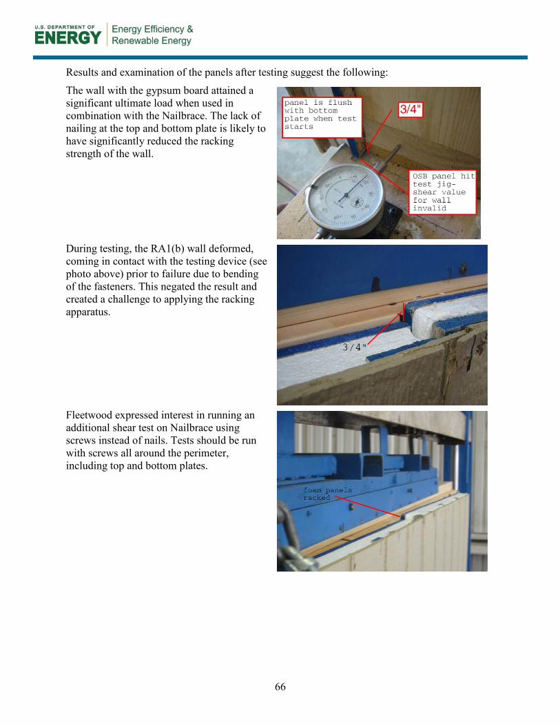
66
Results and examination of the panels after testing suggest the following:
The wall with the gypsum board attained a significant ultimate load when used in combination with the Nailbrace. The lack of nailing at the top and bottom plate is likely to have significantly reduced the racking strength of the wall.
During testing, the RA1(b) wall deformed, coming in contact with the testing device (see photo above) prior to failure due to bending of the fasteners. This negated the result and created a challenge to applying the racking apparatus.
Fleetwood expressed interest in running an additional shear test on Nailbrace using screws instead of nails. Tests should be run with screws all around the perimeter, including top and bottom plates.

67
6 Conclusions
The research described in this report is part of a multiphase program with the goal of identifying and moving toward commercial acceptance of envelope construction methods that are far more efficient than current practice and specifically geared to meet the needs of factory builders. This current effort is focused on wall component development and involved two parts: identifying a range of building solutions that had in common the use of continuous exterior insulation and initial testing of some of the solutions developed.
In identifying solutions the team reached out to six of the nation’s leading insulation suppliers, challenging them to suggest how off-the-shelf or readily developable products could be used as part of a comprehensive solution that meets a set of prescribed performance targets. The results were presented at an Expert Meeting in November 2012. This was a fruitful endeavor with a total of more than 50 unique solutions presented and discussed. In addition to building an impressive array of possible technical solutions, the experience reinforced the value of collaborative research that can result when all stakeholders are invested as research partners. Among other benefits, the team and industry committee were able, with the help and guidance of the insulation companies, to begin to comparatively assess a range of alternate construction methods and materials in a short period of time and to begin to identify materials and solutions that have the greatest potential for factory builders. Specifically, the process is enabling the team to explicitly weigh alternatives based on a number of parameters (manufacturability, thermal performance, moisture balance, etc.) and not just first cost.
Among the observations and conclusions of the design-development stage with the six insulation suppliers are the following:
• The decision about the materials that can be part of a continuous exterior insulation solution will partly depend on the location of the VR. The appropriate location of the VR and the relative perm ratings of materials in the wall continue to be debatable within the industry. These issues will require additional analysis and testing to settle following which changes and clarifications will be needed within building codes, particularly the HUD standards.
• A single product that can be delivered by OEM insulation suppliers that can perform multiple functions (weather barrier, air barrier, structural capacity, etc.) will have an advantage by enabling manufacturers to eliminate production steps associated with applying additional materials to perform those functions. However, these advantages will come with a cost that will need to be carefully weighed against the benefits.
• In the factory building environment where production speed is a principle determinant of profitability, seemingly small considerations, like required fasteners, weight (i.e., transportability) of materials and simplicity of detailing become paramount. For example, technologies that require screws in place of nails may dramatically slow the production process.
• Wall technologies that meet the needs of factory building are proving to be, in many respects, too broad a goal: solutions that are appealing for manufactured home builders may not suit modular builders, and vice versa. This is less a matter of building method than home price point and market orientation (e.g., some factory builders will use very

68
high insulation levels to distinguish their homes and are less concerned about cost because of the relatively high price point). While the project will continue to pursue solutions for both audiences, the technical direction may need to branch in two directions to serve the needs of both.
• There continue to be unresolved technical issues associated with the use of exterior foam insulation that, in many instances, are being addressed by others in parallel with this work. For example, the durability of windows that, while fastened into the structural frame, bear on the insulation is under consideration. The results of those investigations will benefit this research and help the larger building community looking to use exterior foam insulation.
Among the key findings from the limited testing and mockups of the wall designs proposed by Dow and AFM are the following general points:
• The general sense of the technical review group was that Dow’s Styrofoam has real potential and the hurdles to its use and additional effort that will be required to reach proof-of-concept is manageable—Styrofoam is a promising product for factory builders. However, questions about cost, compliance with HUD standards, and production friendliness will need to be addressed.
• AFM’s Nailbrace has much to recommend it, including its ability to be an almost-all-in-one wall solution. However, the preliminary reaction of the industry and supplier group assembled for the test is that the product has significant drawbacks (e.g., need to use screws instead of nails, lack of flexibility with regard to furring location, weight of the panel) that represent formidable hurdles weighing against this option.

69
References
ASTM E564 ― Standard Practice for Static Load Test for Shear Resistance of Framed Walls for Buildings, published by ASTM International, www.astm.org.
ASTM E72-80 ― Standard Test Methods of Conducting Strength Tests of Panels for Building Construction, published by ASTM International, www.astm.org.
BASF. (2013). “R-Value Data for NEOPOR Rigid Thermal Insulation Produced Under Brand Marketing Agreement in the US and Canada.” Memorandum dated January 15, 2013. Wyandotte, MI: BASF. http://styropor.basf.us/files/pdf/2013_01_15_Neopor_R-value_Comprehensive.pdf. Accessed November 2013.
BASF. (2011). Building and Modernizing With NEOPOR. Ludwigshafen, Germany: BASF. www.plasticsportal.net/wa/plasticsEU~en_GB/function/conversions:/publish/common/upload/foams/Neopor_Building_and_modernising_with_Neopor_EN.pdf. Accessed November 2013.
BASF. (2012). “Wall Insulation.” Wyandotte, MI: BASF. www.neopor.basf.us/files/pdf/wall.pdf. Accessed November 2013.
CertainTeed. (2010). “CertaPro Commercial Board Specification Sheet.” Valley Forge, PA: CertainTeed. www.certainteed.com/resources/30-25-021%20CertaProComBoard%20Spc.pdf. Accessed November 2013.
Fox, P.J. (2012). “Building America Advanced Envelope Research—BASF NEOPOR.” Presented at the Building America Expert Meeting, Harrisburg, PA.
HUD. U.S. (1994).Manufactured Housing Construction and Safety Standards, Subpart 3280. Washington, D.C.: U.S. Department of Housing and Urban Development.
JM. (2013a). “Flat & Tapered ValuTherm Polyisocyanurate Roof Insulation.” Denver, CO: Johns Manville. www.specjm.com/files/pdf/RS-5174_ValuTherm.pdf. Accessed November 2013. JM. (2013b). “ValuTherm Roof Insulation.” Denver, CO: Johns Manville. www.specjm.com/files/pdf/RS-5174_ValuTherm.pdf. Accessed November 2013. JM. (2013c). “AP Foil-Faced Polyiso Foam Sheathing.” Denver, CO: Johns Manville. http://www.specjm.com/products/foamboards/APFoil-FacedPolyisocyanurateFoamSheathing.asp. Accessed November 2013. JM. (2009). “AP Foil-Faced Polyisocyanurate Foam Sheathing.” Denver, CO: Johns Manville. www.jm.com/insulation/building_insulation/products/can283_ap_foilfaced.pdf. Accessed November 2013.

70
Levy, E.; Mullens, M.; Tompos, E.; Kessler, B.; Rath, P. (2012). Building America Expert Meeting Report: Advanced Envelope Research for Factory Built Housing. Golden, CO: National Renewable Energy Laboratory. NREL/SR-5500-54439.
Lstiburek, J. (1999). Drainage Planes and Air Spaces. Research Report-9909. Somerville, MA: Building Science Corporation. www.buildingscience.com/documents/reports/rr-9909-drainage-planes-and-air-spaces. Accessed November 2013.
Lstiburek, J. (2006). “BSD 105: Understanding Drainage Planes.” Building Science Digests. Somerville, MA: Building Science Corporation. www.buildingscience.com/documents/digests/ bsd-105-understanding-drainage-planes. Accessed November 2013.
Mallon, B.; Lieburn, B. (2012). “Moisture Protection and Energy Efficiency—Advances in Wall Construction for Energy Efficiency for Factory Built Homes.” Presented at the Building America Expert Meeting, Harrisburg, PA.
ORNL. (2013). Oak Ridge National Laboratory. “WUFI Software.” Oak Ridge, TN: Oak Ridge National Laboratory. http://web.ornl.gov/sci/ees/etsd/btric/wufi/software.shtml. Accessed November 2013.
Tobin, M. (2012). “Presentation to the ARIES Collaborative Building America Advanced Envelope Research.” Presented at the Building America Expert Meeting, Harrisburg, PA.

71
Appendix A: Detailed Test Description
The following tables provide details on the racking tests and mockups conducted on the Styrofoam and Nailbrace-based wall design options. Tabulated information includes intent of test, fastener type for components, wall framing, window framing and other details. Fasteners have been keyed to a list of all the different types used for the project (see Table 26 and Table 27).
Table 22 provides this information on racking tests conducted on multiple iterations of stud walls with Styrofoam.

72
Table 22. Details on Racking Tests—Stud Walls With Styrofoam
Case No.
Insulation Framing
Furring or Strapping Siding Notes Purpose Ultimate
Load R-Value (thickness) Fastener Type Fastener Type Fastener
RD1 (a)
R-5 (1 in.)
Staple, roof nail or cap nail
(1¾ in.) (B)
2 in. × 6 in. NA NA LP SmartSide
⅜ in.
Nail (3 in.)
(D) 5
Baseline for assessing structural integrity of wall with gypsum board.
6,701 lb
RD1 (b)
R-5 (1 in.)
Staple, roof nail or cap nail
(1¾ in.) (B)
2 in. × 6 in. NA NA LP SmartSide
⅜ in.
Nail (3 in.)
(D) 5, 7
Contrast result of wall RD1(a) without gypsum
5,842 lb
RD2 (a)
R-5 (1 in.)
Staple, roof nail or cap nail
(1¾ in.) (B)
2 in. × 6 in. NA NA Cempanel
Nail (3 in.)
(D)
Contrast shear resistance result with LP SmartSide (RD1).
4,523 lb
RD2 (b)
R-5 (1 in.)
Staple, roof nail or cap nail
(1¾ in.) (B)
2 in. × 6 in. NA NA Cempanel
Nail (3in.) (D)
7 Contrast result of wall RD2(a) without gypsum
6,200 lb
RD3 R-10 (2 in.)
Staple, roof nail or cap nail
(2¾ in.) (M or L)
2 in. × 4 in. 2 × 4
HeadLOK 24 in. o.c. vertical
spacing (O)
LP SmartSide ⅜ in.
Nail (2 in.) (C)
5, 6
Assess the impact that a longer fastener has on the shear strength of the wall.
Not tested
Notes: 1. Most testing to be completed (if possible) prior to February 6. Test RD3 will be conducted on February 6 in the morning. While not intended as
“witnessed” ASTM tests, the results are intended to provide a rough gauge on how these walls would likely test out by a third party. 2. All walls except RD3 have interior gypsum board finish with PVA adhesive. 3. No fiberglass insulation or weather barrier required for testing. 4. Panel is an opaque wall section (no windows or doors) 5. LP SmartSide requires 1½ in. penetration into structural framing. Siding to be removed after tests to inspect for damage to the foam by nail routing. 6. Length of fastener to be verified. LP SmartSide specs for walls with foam insulation > 1 in. requires 1½ in. × 4 in. vertical strapping for nailing base. 7. Wall tested without gypsum for comparison with RD1(a)/RD2(a).
Table 23 provides detailed information on racking tests conducted on multiple iterations of stud walls with Foam-Control Nailbrace.

73
Table 23. Details on Racking Tests—Stud Walls With Foam-Control Nailbrace
Case No.
Insulation Framing Furring or
Strapping
Siding Notes Purpose Ultimate
Load R-Value (thickness) Fastener Type Fastener
RA1 (a)
R-5 (1-⅝”)
Nail (3 in.) or Opt-Screw (3 in.) through vertical strip
(E or H)
2 in. × 6 in. NA
LP SmartSide
⅜ in.
2 in. nail (6d ring shank nail)
(attached to vertical strip)
(C)
5
Baseline for assessing structural integrity of
wall Routing out of insulation
by nails following racking test.
7,154 lb
RA1 (b)
R-5 (1-⅝”)
Nail (3 in.) or Opt-Screw (3 in.) through vertical strip
(E or H)
2 in. × 6 in. NA
LP SmartSide
⅜ in.
2 in. nail (6d ring shank nail)
(attached to vertical strip)
(C)
5, 6 Contrast result of wall RA1 without gypsum.
Excessive deflection
RA2 R-10 (2-⅞”)
Nail (4 in.) through
vertical strip (G)
2 in. × 4 in. NA
LP SmartSide
⅜ in.
2 in. nail (6d ring shank nail)
(attached to vertical strip)
(C)
5, 7 Case RA1 with thicker insulative sheathing. Not tested
Notes: 1. Testing to be completed (if possible) prior to February 6. 2. Wall has interior gypsum board finish with PVA adhesive. 3. No fiberglass insulation or weather barrier required for testing. 4. Panel is an opaque wall section (no windows or doors) 5. The sample will be assembled so that the let in furring strips receive the nails or screws and, together with the structural sheathing is assumed to
contribute to wind bracing. This is required to secure the strip for when it receives the siding. 6. Wall tested without gypsum for comparison with RA1. 7. This test is tentative and will be conducted only if time allows.
Table 24 provides detailed information on process mock-ups conducted on multiple iterations of stud walls with Styrofoam. For details on window framing options see Section 4.6.4.

74
Table 24. Details on Mockups—Stud Walls With Styrofoam
Case No.
Insulation
Stru
ctur
al S
heat
hing
Fram
ing
Furring or Strapping Siding Window
Framing
Not
es
Purpose
R-V
alue
(t
hick
ness
)
Fast
ener
Typ
e
Fast
ener
Typ
e
Fast
ener
Det
ail N
o.
Fast
ener
MD1 R-5 (1 in.)
Staple, roof nail or cap nail (1¾
in.) (B) No 2 in. ×
6 in. NA NA LP
SmartSide ⅜ in.
Nail (3 in.)
(D) 1 –
• Baseline for construction evaluation Evaluate construction details at openings and roof and floor intersections Assess difficulty in routing out for openings
MD2 R-5 (1 in.)
Staple, roof nail or cap nail (1¾
in.) (B) No 2 in. ×
6 in. NA NA Vinyl Nail
(3 in.) (D)
3 – • Assess additional issues or
advantages (speed of assembly) when using vinyl siding with staples.
MD3 R-5 (1 in.)
Staple, roof nail or cap nail (1¾
in.) (B)
Yes (OSB)
2 in. × 6 in. NA NA Vinyl
Nail (3 in.)
(D) 2 –
• Represent typical construction Assess difficulty in routing out for openings
MD4 R-10 (2 in.)
Staple, roof nail or cap nail (2¾
in.) (M or L)
No 2 in. × 4 in. 2 × 4
HeadLOK 24 in.o.c.
vert. spacing
(O)
LP SmartSide
⅜ in.
Nail (2 in.)
(C) 1 – 3
• Evaluate construction details at openings and roof (side and gable end) and floor intersections Assess difficulty in routing out for openings
Notes: 1. Omit gypsum and fiberglass from mockup walls to view missed fasteners from siding to studs. Include flashing around windows and doors, air barrier
and tapes as required for a typical installation. 2. Reuse windows and doors, if possible. 3. Test MD4 will be conducted only if time allows.

75
Table 25 provides detailed information on process mock-ups conducted on multiple iterations of stud walls with Foam-Control Nailbrace.
Table 25. Details on Mockups—Stud Walls With Foam-Control Nailbrace
Case No.
Insulation
Stru
ctur
al
Shea
thin
g
Fram
ing
Siding Window Framing
Not
es
Purpose
R-v
alue
(th
ickn
ess
)
Fast
ener
Typ
e
Fast
ener
Det
ail N
o.
Fast
ener
MA1 R-5 (1-⅝”)
Nail (3 in.) through
vertical strip (E or H)
No 2 in. × 6 in.
LP SmartSide
⅜ in.
2 in. nail (6d ring shank nail)
(attached to vertical strip)
(C)
1 – 3, 4
• Baseline for construction evaluation • Evaluate construction details at
openings and roof (side and gable end) and floor intersections
• Assess difficulty in routing out for openings
MA2 R-5 (1-⅝”)
Nail (3 in.) through
vertical strip (E or H)
No 2 in. × 6 in. Vinyl Staple into
nailing strip (C) 3 – 4 • Assess additional issues or advantages
(speed of assembly) when using vinyl siding with staples.
MA3 R-5 (1-⅝”)
Nail (3 in.) through
vertical strip (E or H)
No 2 in. × 6 in. Vinyl Staple into
nailing strip (C) 2 4 • Assess additional issues or advantages
(speed of assembly) when using vinyl siding with staples.
Notes: 1. Omit gypsum and fiberglass from mock up walls to view missed fasteners from siding to studs. Include flashing around windows and doors, air barrier and tapes as
required for a typical installation. 2. Reuse windows and doors, if possible 3. Specification of the fastener for attaching the siding is based on LP Technical Bulletin SIP No. 2074, Table 4 (http://www.r-
control.com/downloads/techbulletin/rcontrol2074.pdf) Fastener for Nailbrace assumed to penetrate a total of 1½” of the structural sheathing and structural framing. The siding is held by the nail into the vertical strip embedded in Nailbrace.

76
Appendix B: Equipment and Material Needs
The section provides details on the equipment and material needs for the testing and demonstration.
Fasteners and Associated Tools Fasteners and associated tools required for the meeting are listed in Table 26 and Table 27.
Table 26. Fasteners and Associated Tools (Senco Products)
Code Fasteners Standard Description Quantity Thousands Finish
A Q25BAB 2½ in. × 7/16 Crn 15 Ga Staple 2 carton 10/m Galv B P21BAB 2 in. × 1 in. Crn 16 Ga Staple 2 carton 10/m Galv
C G621ASBX 2 in. × 0.113 RS Nail 2 carton 5/m Hot dip galv
D H627ASBX 3 in. × 0.120 RS Nail 2 carton 5/m Hot dip galv
E K528ASBX 3¼ in. × 0.131 Coated Nail 2 carton 5/m Hot dip galv
F K529APBX 3½ in. × 0.131 Coated Nail 2 carton 5/m Bright G KC31 4 in. Nail – – –
Code Screws Description Quantity Thousands Finish
H 08F300Y 3 in. × # 8 Wood Screw 2 tubs 1.6/m Yellow Zinc
Code Special Product Description Quantity – Finish
I SQSSXP 3.5 90MM Europe 1 J WC130SP 4½ in. wide crn Europe 1 K S28BAB 3 in. × 1/2 in. Crn Staple Europe 3 carton Galv L S29BAB 3½ in. × ½ in. Crn Staple Europe 3 carton Galv M SP30BAB 4 in. × 1 in. Crn Staple Europe 4 carton Galv N SP29BAB 3½ in. × 1 in. Crn Staple Europe 4 carton Galv
Tool Identifier Description Quantity – –
4Y0001N WC200 XP WC Stapler 2 5B0001N SN951XP Framing Nailer 2 660101N SQS55 Stapler 2 6Y00011N DS340A/C Screwdriver 1 2P0001N DS275-18V Cordless Screwdriver 1

77
The following screws were used to attach 2 × 4 (nominal) furring over 2 in. of Styrofoam with 2 in. embedment into the studs. Screws require Spider drive bits.
Table 27. Fasteners and associated tools (FastenMaster products)
Code Screws Description Quantity Pieces Finish O HeadLOK 5½ in. min 1 box 50
Insulation and Associated Products
Styrofoam tests (Supplier: DOW) • 1—Pallet or unit of 4 ftx9 ftx1 in. Dow Styrofoam sheathing panels 96 pcs.
• 1—Pallet or unit of 4 ftx9 ftx2 in. Dow Styrofoam sheathing panels 48 pcs.
• 1—Froth Pak 220 (insulation not sealant) kit, with hose and nozzles
• 1—Case of Great Stuff Gaps and Cracks Pro
• 1—Case of Great Stuff Adhesive
• 1—Case of Great Stuff Window and Door Pro
• 2—Pro 14 Great Stuff Dispensers (guns)
• 1—Case of Great Stuff gun cleaner
• 1—Case Weathermate Construction Tape 2.875 in. wide
• 1—Case Weathermate Construction Tape 1.875 in. wide
• 1—Case of Weathermate Straight Flashing 4 in. × 100 ft
• 1—Case of Weathermate Straight Flashing 6 in. × 100 ft
• 1—Box Weathermate Flexible Flashing 6 in.
• 1—Box Weathermate Flexible Flashing 9 in.
• 1—Box Weathermate window sill pans
Foam-Control Nailbrace tests (Supplier: AFM Corp.) • 6 pieces—1.625 in. × 4 ft × 8 ft, Foam Control Nailbrace panels
• 8 pieces—1.625 in. × 4 ft × 9 ft, Foam Control Nailbrace panels
• 4 pieces—2.875 in. × 4 ft × 9 ft, Foam Control Nailbrace panels
• 6 rolls edge sealing tape
Siding
LP SmartSide siding (Supplier: LP Corp.) • 18 each—⅜ in. 4 ft × 8 ft 8 in. o/c SmartSide Panel Siding
• 18 each—7/16 in. 4 ft × 8 ft 8 in. o/c SmartSide Panel Siding

78
Cempanel (Supplier: Cavco) • 10 sheets—4 ft × 8 ft each
Vinyl (Supplier: BlueLinx Corp.) • 32 squares—D5 Dutch Lap Parkside #115 Pearl
• 50 pieces—Sturdy Vinyl Starter Strip #303
• 40 pieces—⅝ in. J-Channel Pearl #36585
• 10 pieces—3 in. Outside Corner Post Pearl #40022
• 10 pieces—4 in. Outside Corner Post Pearl #40020
Window Framing
Metal L-clips (Supplier: AFM Corp.) • 10 pieces—4 ft long R-5 L-clips
• 4 pieces—R-10 L-clips
Other Wall Build Materials (Supplier: Cavco) (quantities as required)
• Framing
• Gypsum board
• OSB
• Doors
• Windows and doors
• Flashing
• Weather resistant barrier
• Materials for partial floor and roof

DOE/GO-102014-4293 ▪ January 2014
Printed with a renewable-source ink on paper containing at least 50% wastepaper, including 10% post-consumer waste.
buildingamerica.gov