Embed Size (px)
Citation preview
CHAROTAR UNIVERSITY OF SCIENCE & TECHNOLOGY
FACULTY OF TECHNOLOGY & ENGINEERING
CHAMOS Matrusanstha Department of Mechanical Engineering
Page 1 of 27
Fluid Machines-2 (ME 401.01.01) Date:
INDEX
Sr.
No. Date Title
No. of
Pages Marks
Date
of
Asse
ssme
nt
Sign of
Faculty
1 Study and plotting of NACA aerofoil.
2 Construction of a blade profile by
circular arc method.
3
Study of surging and stalling in
compressor.
4 Study of pressure distribution over an
aerofoil at different angular positions.
5 Study of Compressors and Turbines
cascades with different types of angles.
6 Drag characteristics of models.
7 Study about lift and drag
characteristics of an aerofoil.
8 Study of Cascade wind tunnel and
different losses.
CHAROTAR UNIVERSITY OF SCIENCE & TECHNOLOGY
FACULTY OF TECHNOLOGY & ENGINEERING
CHAMOS Matrusanstha Department of Mechanical Engineering
Page 2 of 27
Fluid Machines-2 (ME 401.01) Date:
EXPERIMENT NO. 1
STUDY AND PLOTTING OF AN AEROFOIL
AIM:
To study about different terminologies and plotting of
1. NACA (National Advisory Committee for Aeronautics).
2. Zuhokowiski aerofoil.
OBJECTIVES: 1. Study about the concept and different terminologies of an aerofoil.
2. To get the design and plotting idea for NACA and Zuhokowiski aerofoil.
THEORY:
Aerofoil is a section used in blades. An aerofoil blade is a stream line body having a thick
round leading edge and thin trailing edge. When fluid passes through an aerofoil or an
aerofoil moves through any fluid the upward lift is produced due to pattern of stream line
which causes a difference of pressure between the upper and lower surface of aerofoil. To
increase speed and to increase flight speed, angle of incident can also be increased.
Aerofoil is shaped in such a way that the value of ‘Drag force (retarding force)’ is less.
It has rounded nose.
Pointed tail.
Gentle curvature.
Application:-
1. They are used in planes as wings for producing and maintaining lift.
2. Aerofoils are used as radar for direction control.
3. They are used as blades in flow propellers, turbines and compressors.
4. Lift is used for forward motion of an aeroplane.
TERMINOLOGY:-
Many blade profiles are formed by bending a symmetrical aerofoil section on a curved mean
line. In this case the base profile is defined by diving a major axis into equally spaced stations
designated as a percentage of the length & specifying the height on axis to profile at each
station.
The nose or leading edge is usually a circular & blended into the main profile & specified by
its radius (as a % of the max. thickness).
The trailing edge is ideally sharp i.e. is of zero radius but as this is impossible from length
considerations so it has also a circular arc as that for leading edge.
The centre line of blade curvature above & below which material is uniformly dispersed is
known as camber line. The maximum rise of mean line from the chord line is called camber.

CHAROTAR UNIVERSITY OF SCIENCE & TECHNOLOGY
FACULTY OF TECHNOLOGY & ENGINEERING
CHAMOS Matrusanstha Department of Mechanical Engineering
Page 3 of 27
The line joining leading and trailing edge is called chord line. The angle between the free
stream flow velocity and the chord line of an aerofoil is called an angle of attack. The ratio
of blade height to blade length is called angle ratio.
The NACA airfoils are airfoil shapes for aircraft wings developed by the National Advisory
Committee for Aeronautics (NACA). The shape of the NACA airfoils is described using a
series of digits following the word "NACA." The parameters in the numerical code can be
entered into equations to precisely generate the cross-section of the airfoil and calculate its
properties.
The NACA standard aerofoils series is assigned by four digits as explained below
- The first digit indicate the maximum camber in % of chord. It stands for maximum
camber in 100th of chord length.
- The second digit indicate the position of maximum camber in 10th of chord from
leading edge. It shows the position of maximum camber from leading edge in a 10th of
chord length.
- The third and fourth digits indicate the maximum thickness in % of chord. It stands
for thickness in 100th of chord length.
The mean camber line of four digit series consists of two parts of two parabola. The
equations of which are given below

CHAROTAR UNIVERSITY OF SCIENCE & TECHNOLOGY
FACULTY OF TECHNOLOGY & ENGINEERING
CHAMOS Matrusanstha Department of Mechanical Engineering
Page 4 of 27
where 0
where
Where,
X= position of X coordinate
m = Maximum camber in % of chord.
Xm =Position of maximum camber in 10th of chord.
t = Maximum thickness of aerofoil.
Yt= Thickness distribution in % of chord.
Leading edge radius is found by Rt=1.1*t2.
OBSERVATION TABLE:-
Camber Aerofoil:-
NACA CHORD LENGTH =
Sr No. Position of
camber
Camber distances Blade thickness
X X
(mm)
Yc1 Yc1
(mm)
Yc2 Yc2
(mm)
Yt Yt
(mm)
1 0.0
2 0.05
3 0.10
4 0.20
5 0.30
6 0.40
7 0.50
8 0.60
9 0.70
10 0.80
11 0.90
12 1.0

CHAROTAR UNIVERSITY OF SCIENCE & TECHNOLOGY
FACULTY OF TECHNOLOGY & ENGINEERING
CHAMOS Matrusanstha Department of Mechanical Engineering
Page 5 of 27
Uncamber Aerofoil:-
NACA CHORD LENGTH =
Sr No. Position of
camber
Camber distances Blade thickness
X X
(mm)
Yc1 Yc1
(mm)
Yc2 Yc2
(mm)
Yt Yt
(mm)
1 0.0
2 0.05
3 0.10
4 0.20
5 0.30
6 0.40
7 0.50
8 0.60
9 0.70
10 0.80
11 0.90
12 1.0
CALCULATION:-

CHAROTAR UNIVERSITY OF SCIENCE & TECHNOLOGY
FACULTY OF TECHNOLOGY & ENGINEERING
CHAMOS Matrusanstha Department of Mechanical Engineering
Page 6 of 27
ZUHOKOWISKI AEROFOIL:
Zuhokowiski said that profile obtained by confined transformation of a circle. It makes a
good wing shape and that the lift can be calculated from the known flow rate with respect to a
circular cylinder.
The transformation formula which was derived by him for this process was,
W=z+1/z
Where z=x+iy
CONCLUSION:-
Marks obtained: Signature of faculty: Date:

CHAROTAR UNIVERSITY OF SCIENCE & TECHNOLOGY
FACULTY OF TECHNOLOGY & ENGINEERING
CHAMOS Matrusanstha Department of Mechanical Engineering
Page 7 of 27
Fluid Machines-2 (ME 401.01)
Date:
EXPERIMENT NO. 2
CONSTRUCTION OF BLADE PROFILE BY CIRCULAR
ARC METHOD
AIM:
construction of blade profile by circular arc method.
Objectives:
1. study and plotting of aerofoil geometry with different angles.
2. To understand the the concept of aerofoil for compressor or turbine.
Data:
Pitch s =
Actual chord length L =
Inlet flow angle (α1) =
Outlet flow angle (α2) =
Base profile name =
Incident angle i =
Notations:
γ = stagger angle.
β1 = inlet blade angle.
β2 = outlet blade angle.
θ = camber angle.
i = α1 - β1
Deviation δ = α2 – β2
δ = m θ (where c = chord length)
m= 0.23 * + 0.02 * α2
=
γ = β1 – θ1 and γ = β2 + θ2
β1 – β2 = θ1 + θ2
Rt = arc radius
= r * θ
Required thickness ya = * yt

CHAROTAR UNIVERSITY OF SCIENCE & TECHNOLOGY
FACULTY OF TECHNOLOGY & ENGINEERING
CHAMOS Matrusanstha Department of Mechanical Engineering
Page 8 of 27
Calculation Table:
X
θ Rt = r * θ
Yt ya = * yt
0
10
20
30
40
50
60
70
80
90
100
QUESTIONS:
1. Plot the aerofoil cascade for given NACA aerofoil with given angles.
CONCLUSION:
REFERENCES:
1. Turbines, compressors and fans by S.M.Yahya, Tata Mcgraw hill Publications.
Marks obtained: Signature of faculty: Date:

CHAROTAR UNIVERSITY OF SCIENCE & TECHNOLOGY
FACULTY OF TECHNOLOGY & ENGINEERING
CHAMOS Matrusanstha Department of Mechanical Engineering
Page 9 of 27
Fluid Machines-2 (ME 401.01) Date:
EXPERIMENT NO. 3
SURGING AND STALLING IN COMPRESSORS
AIM:
To study surging and stalling in the compressor.
OBJECTIVES:
To understand the theoretical concept of surging and stalling.
THEORY:
All turbo compressors have certain characteristics of instability over their operational
range. These instabilities are associated with the separation of the flow from the blade or the
complete breakdown of the flow. They are usually of two types,
1. Stall
2. Surge.
Both of these instabilities are associated with the positive slope of the pressure v/s mass flow
areas of the compressor.
STALLING
Consider a typical cascade of blades. It is known that the cascade blades at certain
angle of attack with the moving blade, develops little force which increases gradually.
However, further increase in the angle of attack beyond the critical value results in the drastic
decrease in the lift coefficient along with the rapid increase in the drag coefficient. This
increases the angle β1 and not angle β2. As for air, it will be difficult to flow over the convex
surface of blade which increases β1 with which angle β2 also changes resulting in the increase
in separation of the flow, thereby reduces the lift coefficient, this phenomenon is called as
stalling. Due to this, the pressure will be reduced and the loss of pressure causes reduction of
delivery pressure and intermediate back flow occurs. A similar thing happens when the angle
β1 is reduced beyond certain value.
Stall occurring due to high value of angle of attack is called as positive stall while that
due to low value of angle of attack is called as the negative stall.

CHAROTAR UNIVERSITY OF SCIENCE & TECHNOLOGY
FACULTY OF TECHNOLOGY & ENGINEERING
CHAMOS Matrusanstha Department of Mechanical Engineering
Page 10 of 27
Figure: Stall propagation in compressor blade row
SURGING
The phenomenon of surging can be explained with reference to the characteristic
curves for the constant speed operation of compressor starting from low mass flow rates. The
Figure: Surging in compressor
pressure increases with an increase in mass flow until the flow rates reaches to its peak value.
This region has a positive slope and it is unstable. Beyond the point B upto point A the
compressor operates normally in stable region.

CHAROTAR UNIVERSITY OF SCIENCE & TECHNOLOGY
FACULTY OF TECHNOLOGY & ENGINEERING
CHAMOS Matrusanstha Department of Mechanical Engineering
Page 11 of 27
CONTROL
There is no absolute remedy for surging. Usually the pressure ratio in a single stage is
limited to about 7 to 9 and for two stage compression, the pressure ratio as high as 12 to 16
can be obtained. Inter stage blades where by a portion of the compressor air flow is bled off,
helps to reduce the instability at low speeds.
QUESTIONS
1. What is surging in axial flow compressor? What are its effects? Describe briefly.
2. What is stalling in axial flow compressor? How it is developed?
3. What is rotating stall? Explain briefly the development of small and large stall cells in
an axial flow compressor.
CONCLUSION:-
Marks obtained: Signature of faculty: Date:
CHAROTAR UNIVERSITY OF SCIENCE & TECHNOLOGY
FACULTY OF TECHNOLOGY & ENGINEERING
CHAMOS Matrusanstha Department of Mechanical Engineering
Page 12 of 27
Fluid Machines-2 (ME 401.01) Date:
EXPERIMENT NO. 4
STUDY OF PRESSURE DISTRIBUTION OVER AN
AEROFOIL AT DIFFERENT ANGULAR POSITION.
AIM:
Study pressure distribution over an aerofoil at different angular position.
OBJECTIVES: 1. Study the concept and effect of pressure over an aerofoil at different points on upper and
lower surface.
2. To study the effect of change in pressure for different angular position of an aerofoil.
THEORY:
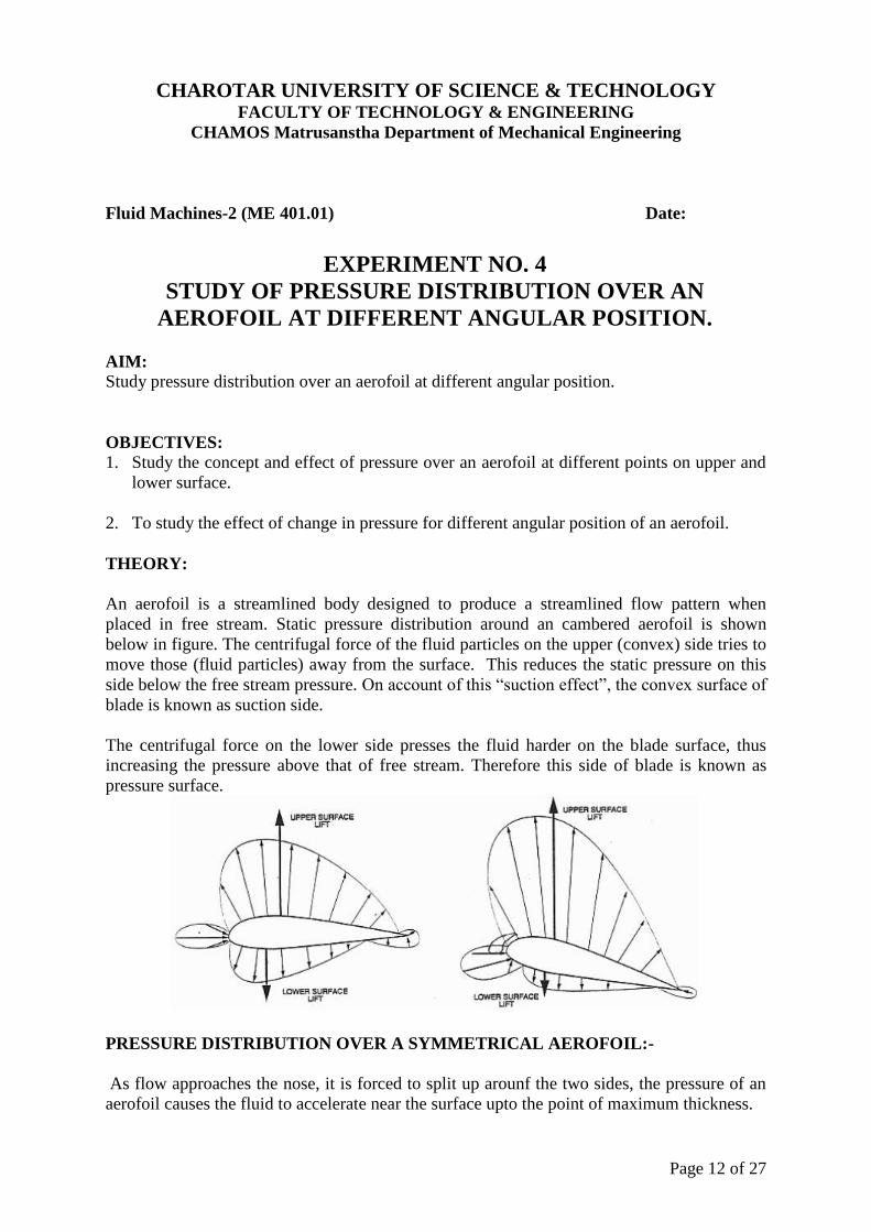
An aerofoil is a streamlined body designed to produce a streamlined flow pattern when
placed in free stream. Static pressure distribution around an cambered aerofoil is shown
below in figure. The centrifugal force of the fluid particles on the upper (convex) side tries to
move those (fluid particles) away from the surface. This reduces the static pressure on this
side below the free stream pressure. On account of this “suction effect”, the convex surface of
blade is known as suction side.
The centrifugal force on the lower side presses the fluid harder on the blade surface, thus
increasing the pressure above that of free stream. Therefore this side of blade is known as
pressure surface.
PRESSURE DISTRIBUTION OVER A SYMMETRICAL AEROFOIL:-
As flow approaches the nose, it is forced to split up arounf the two sides, the pressure of an
aerofoil causes the fluid to accelerate near the surface upto the point of maximum thickness.

CHAROTAR UNIVERSITY OF SCIENCE & TECHNOLOGY
FACULTY OF TECHNOLOGY & ENGINEERING
CHAMOS Matrusanstha Department of Mechanical Engineering
Page 13 of 27
At the leading edge (LE) or midpoint of the nose, there is a stagnation point, where ideally
the streamline is normal to the body.
After the point of maximum thickness, the fluid starts to close in again & its velocity
decreases ideally with another stagnation point at the trailing edge.
The variation of velocity causes a change of static pressure according to the bernoulli’s
equation and if the variation is large then there is a correspondingly large pressure gradient.
If the pressure gradient is adverse then separation may take place. Hence the object of
streamlining is to avoid large changes of velocity.
The pressure distribution over upper and lower surfaces are plotted in a non dimentional
forms in the form of pressure co efficient
PRESSURE DISTRIBUTION OVER AN INCLINED AEROFOIL:-
In this case, the pressure distribution over the top and bottom surfaces is no longer the same.
On the top surface the velocity is caused due to change very rapidly and over the rear half,
the pressure gradient is so severe that separation occurs well forward of the trailing edge.
The bottom surface on the other hand, has a much higher average pressure resulting in
pressure distribution.
With an unbalanced pressure then there is a net force in the upward direction called as lift.
A similar effect is produced by an unsymmetrical profile with its major axis parallel to the
flow or by curving the axis of particle or by giving it camber
Here NACA 0018 aerofoil with axial chord -16cm and 29cm span with 12 pressure taps is
provided to determine pressure distribution over the surface of aerofoil. Material of aerofoil is
aluminium.

CHAROTAR UNIVERSITY OF SCIENCE & TECHNOLOGY
FACULTY OF TECHNOLOGY & ENGINEERING
CHAMOS Matrusanstha Department of Mechanical Engineering
Page 14 of 27
Pitot tube Static Pressure
H1 H2 Q V
m/sec
1 2 3 4 5 6 7 8 9 10 11 12 atm
Aerofoil
Inc=-
15°
Aerofoil
Inc=-
10°
Aerofoil
Inc=-5°
Aerofoil
Inc=0°
Aerofoil
Inc=5°
Aerofoil
Inc=10°
Aerofoil
Inc=15°
CHAROTAR UNIVERSITY OF SCIENCE & TECHNOLOGY
FACULTY OF TECHNOLOGY & ENGINEERING
CHAMOS Matrusanstha Department of Mechanical Engineering
Page 15 of 27
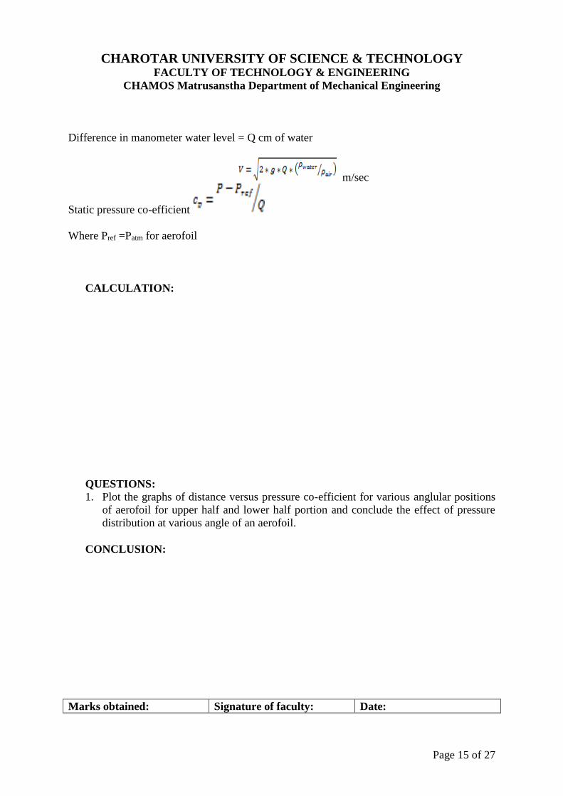
Difference in manometer water level = Q cm of water
m/sec
Static pressure co-efficient
Where Pref =Patm for aerofoil
CALCULATION:
QUESTIONS:
1. Plot the graphs of distance versus pressure co-efficient for various anglular positions
of aerofoil for upper half and lower half portion and conclude the effect of pressure
distribution at various angle of an aerofoil.
CONCLUSION:
Marks obtained: Signature of faculty: Date:

CHAROTAR UNIVERSITY OF SCIENCE & TECHNOLOGY
FACULTY OF TECHNOLOGY & ENGINEERING
CHAMOS Matrusanstha Department of Mechanical Engineering
Page 16 of 27
Fluid Machines-2 (ME 401.01) Date:
EXPERIMENT NO. 5
STUDY OF TURBINES AND COMPRESSORS CASCADES
WITH DIFFERENT TYPES OF ANGLES
AIM:
To study about blades of a given shape arranged in a different manner in the cascades of
turbines and compressors.
OBJECTIVES: 1. Study about the various angles in the cascades for turbines and compressors.
2. To derive the equation for turbine and compressors cascades.
THEORY:
Cascade Nomenclature: An aerofoil is build up around a basic camber line, which is usually a
curricular or a parabolic arc (figure below). A camber line is thus the skeleton of the aerofoil. A thickness t is distributed over the camber line with the leading and trailing edge circles that finally form an aerofoil.
In the above figure, the dotted line indicates the camber line and 'a' is the distance from the leading edge for maximum camber and 'b' is the maximum displacement from the chord line. A cascade geometry is defined completely by the aerofoil specification, pitch-chord ratio (pitch is the spacing
between two consecutive blade) and the chosen setting i.e. stagger angle ( ץ ) (shown below).
is called the aerofoil camber angle i.e. = X1+X2
For a circular arc, X1 = X2 = /2 and a/c = 0.5.
For a parabolic arc, a/c < 0.5.

CHAROTAR UNIVERSITY OF SCIENCE & TECHNOLOGY
FACULTY OF TECHNOLOGY & ENGINEERING
CHAMOS Matrusanstha Department of Mechanical Engineering
Page 17 of 27
Compressor Cascade
The different geometric angles, blade setting and their relationship with the flow angles for a compressor cascade are defined below.
;stagger angle ( positive for a compressor cascade) = ץ
= blade inlet angle = X1+ ץ ;
= blade outlet angle = ץ – X2
The angle of incidence 'i' is the angle made by the inlet flow with the camber line. Under a perfect
situation, the flow will leave along the camber line at the trailing edge of the blade. But it does not
really happen so and there is a deviation which is denoted by .
Thus, the air inlet angle is equals to, α1 = i + X1 +ץ
And air outlet angle, α2 = ץ– X2 – δ
Hence, ε = deflection of flow =
= (X1+X2) + i – δ
Turbine Cascade
The different geometric angles and the blade setting of a turbine cascade are shown in the figure below.

CHAROTAR UNIVERSITY OF SCIENCE & TECHNOLOGY
FACULTY OF TECHNOLOGY & ENGINEERING
CHAMOS Matrusanstha Department of Mechanical Engineering
Page 18 of 27
.stagger is the stagger which is negative for a turbine cascade ץ
CONCLUSION:-
QUESTIONS:
1. Define the following
(i) Camber angles (ii) Blade Angles (iii) Gas angles (iv) Deviation angle.
2. Derive equation which proves that the deflection angle is the sum of the air angle
at the entry and exit for the compressor.
3. Prove that the fluid deflection through the blade is defined as ε=α1-α2 for the
compressor.
4. What is angle of incidence? What are the effects of positive and negative
incidence?
5. Show the stagger, incidence and deviation angles for both turbine and
compressor.
Marks obtained: Signature of faculty: Date:

CHAROTAR UNIVERSITY OF SCIENCE & TECHNOLOGY
FACULTY OF TECHNOLOGY & ENGINEERING
CHAMOS Matrusanstha Department of Mechanical Engineering
Page 19 of 27
Fluid Machines - II (ME - 401.01) Date:
Experiment No. 6
DRAG CHARACTERISTICS OF MODELS
AIM:
To study drag characteristics of models
OBJECTIVES:
To determine drag force of a models
APPARATUS:
1. The total length of the wind tunnel is about 5.0m. The axial flow fan and the duct is
0.6m long. The maximum height is about 2.0m.
2. Test section of 30cm * 30cm cross section and 100cm length with thick Plexiglas
window.
3. Axial flow fan with aluminium cast airfoil shaped blades driven by a 5.0KW AC
motor mounted outside the duct.
4. The test section velocity is varied by changing the frequency with the variable
frequency drive.
THEORY:
To understand the basic concept of drag and lift, let us consider fluid flows at a
uniform velocity U over a stationary body of arbitrary shape as shown in fig. The resultant
force (FR) exerted by the fluid on the body is normal to the surface of the body. The resultant
forces acting on the body can be resolved into two components: one in the direction of flow,
known as drag force (FD) and the other perpendicular to the direction of flow known as lift
force (FL). The determination of the lift and drag forces is very important in many
engineering applications, for example lift force during take-off of an aeroplane, drag force on
an automobile, etc.
Figure: Lift and drag on a stationary body

CHAROTAR UNIVERSITY OF SCIENCE & TECHNOLOGY
FACULTY OF TECHNOLOGY & ENGINEERING
CHAMOS Matrusanstha Department of Mechanical Engineering
Page 20 of 27

CHAROTAR UNIVERSITY OF SCIENCE & TECHNOLOGY
FACULTY OF TECHNOLOGY & ENGINEERING
CHAMOS Matrusanstha Department of Mechanical Engineering
Page 21 of 27
OBSERVATION TABLE:
S.
No.
Models Area of models
sq.m
Pitot tube
q cm of
water
Velocity V
m/sec
Drag CD
Kgf N
1. Rectangle 0.0079
2. Square 0.0079
3. Circle 0.0079
4. Sphere 0.0079
5. Cup 0.0079
6. Hemisphere 0.0079
7. Car 0.0023
8. Jeep 0.0023
9. Truck 0.0023
Calculation:
V=13.0 q m/sec
CD= Drag/(10×q×Area)
Conclusion:
QUESTIONS:
1. What do you mean by coefficient of drag and coefficient of lift?
2. Derive an expression for drag and lift.
3. What are the factors that influence the total drag on a body?
3. Explain Magnus effect of lift.
Marks obtained: Signature of faculty: Date:

CHAROTAR UNIVERSITY OF SCIENCE & TECHNOLOGY
FACULTY OF TECHNOLOGY & ENGINEERING
CHAMOS Matrusanstha Department of Mechanical Engineering
Page 22 of 27
Fluid Machines-2 (ME 401.01) Date:
Experiment No. 7
LIFT/DRAG CHARACTERISTICS OF AEROFOIL
AIM:
To study lift/drag characteristics of Aerofoil
OBJECTIVES:
To determine lift/drag force of aerofoil
APPARATUS:
1. The total length of the wind tunnel is about 5.0m. The axial flow fan and the duct is
0.6m long. The maximum height is about 2.0m.
2. Test section of 30cm * 30cm cross section and 100cm length with thick Plexiglas
window.
3. Axial flow fan with aluminium cast airfoil shaped blades driven by a 5.0KW AC
motor mounted outside the duct.
4. The test section velocity is varied by changing the frequency with the variable
frequency drive.
THEORY:
One of the most common practical engineering applications of the concept of lift
and drag is the design of wing used for different applications such as airplane wings,
propellers and impeller blades of turbo machinery. An airfoil is the form of the cross section
at any point along the wing. The shape of the airfoil should be such that it maximizes the lift
and minimizes drag.
Figure: Airfoil geometry

CHAROTAR UNIVERSITY OF SCIENCE & TECHNOLOGY
FACULTY OF TECHNOLOGY & ENGINEERING
CHAMOS Matrusanstha Department of Mechanical Engineering
Page 23 of 27
OBSERVATION TABLE:
Incidence
angle
Pitot tube Velocity Lift Drag
CL CD CL/CD
Deg. q cm of
water V m/sec Kgf N Kgf N

CHAROTAR UNIVERSITY OF SCIENCE & TECHNOLOGY
FACULTY OF TECHNOLOGY & ENGINEERING
CHAMOS Matrusanstha Department of Mechanical Engineering
Page 24 of 27
Calculation:
V=13.0 q m/sec
CL= Lift/ (10×q×Area)
CD= Drag/ (10×q×Area)
Area of Aerofoil= (0.16×0.25) sq.m
Conclusion:
QUESTIONS:
1. Describe an aerofoil.
2. Define lift and drag coefficient for an aerofoil? How does it vary with the angle of attack?
Marks obtained: Signature of faculty: Date:

CHAROTAR UNIVERSITY OF SCIENCE & TECHNOLOGY
FACULTY OF TECHNOLOGY & ENGINEERING
CHAMOS Matrusanstha Department of Mechanical Engineering
Page 25 of 27
Fluid Machines-2 (ME 401.01) Date:
Experiment No. 8
Cascade wind tunnel and different types of losses.
AIM:
To study about cascade wind tunnel and various losses associated with it.
OBJECTIVES:
Study about principle parts of cascade wind tunnel and performance of cascade blades.
To study about aerodynamic losses occurring in a cascade.
THEORY:
A row of blades representing the blade ring of an actual turbo machine is called cascade, grid,
lattice or a mesh of blades. In a straight or rectilinear cascade blades are arranged in a straight
line. The blades can also be arranged in an annulus, thus representing an actual blade row.
This arrangement is known as an annular cascade and is closer to the real-life situation. The
aforementioned arrangements are employed for the cascades of axial-flow turbo machines.
Construction of a cascade:
Assembly of a number of blades of a given shape and size at the required pitch(s) and stagger
angle (γ) is required for a construction of a cascade. The assembly is then fixed on the test
section of a wind tunnel as shown in below figure. Air at slight pressure and near ambient
temperature is blown over the cascade of blades to simulate the flow over an actual blade row
in a turbo machine. Information through cascade tests is useful in predicting the performance
of blade rows in an actual machine. These tests can also be employed in determining the
optimum design of a blade row for prescribed conditions.

CHAROTAR UNIVERSITY OF SCIENCE & TECHNOLOGY
FACULTY OF TECHNOLOGY & ENGINEERING
CHAMOS Matrusanstha Department of Mechanical Engineering
Page 26 of 27
Wind tunnel and the cascade both can be constructed in wood. The cost of such equipment
and the test thereof is much lower than an actual turbo machine stage in metal and its testing.
In a blower type of a cascade tunnel as in figure, air is discharged into the laboratory without
causing any problems to the personal and equipment. Blades for a cascade can be
manufactured from wood, epoxy resin, glass wool, araldite or aluminum. To reduce the
quantity of material and weight blades can be made hollow: this also facilitates the provision
of static pressure tubes around their profiles. They can also be made by suitably bending
brass, copper or Perspex sheets.
If the blades are manufactured from wood, it should be of good quality like teak or deodar
and perfectly seasoned. Sufficient time should be allowed for setting during their
manufacture. This allows the blades to dry up and settle to their final shape and size, and
minimizes any deformation after the final finish. Wooden blades should be given a hard
coating of resin or some other material to make it durable.
Cast aluminum or araldite blades have a good surface finish and do not require any polishing.
Seven or more blades of equal lengths are arranged at the required pitch and stagger and then
screwed between the top and bottom planks. The length AB of the exit of the test section as
in figure must be an exact multiple of the blade pitch(s). The inclination of the test section
side wall at AB is such that the flow enters the cascade at zero incidence.
Cascade Tunnel and losses:
A wind tunnel is required to blow a jet of air over the cascade of blades. Various types of
tunnels can be used for cascade testing depending on the type and range of information
required. Figure shows a blower type of a cascade tunnel. Its principal parts are the blower,
diffuser, settling chamber, contraction cone and test section.
The types of aerodynamic losses occurring in the compressor cascade are same as for the
turbine cascade. Their exact nature and magnitudes are different on account of the
decelerating flow in compressor cascade. Aerodynamic losses occurring in most of the turbo
machines arise due to growth of the boundary layer and its separation on the blade and
passage surfaces. Others occur due to wasteful circulatory flows and the formation of shock
waves. Non-uniform velocity profiles at the exit of the cascade lead to another type of loss
referred to as the mixing or equalization loss. Different types of losses are below
1. Profile loss 3. Secondary loss
2. Annulus loss 4. Tip clearance loss.
Questions:
1. Draw a cascade wind tunnel with its different parts and explain working and
construction of it.
2. Explain following losses with neat sketch for turbine and compressor cascades.
(i) Profile loss (iii) Secondary loss
(ii) Annulus loss (iv) Tip clearance loss.
Marks obtained: Signature of faculty: Date:

CHAROTAR UNIVERSITY OF SCIENCE & TECHNOLOGY
FACULTY OF TECHNOLOGY & ENGINEERING
CHAMOS Matrusanstha Department of Mechanical Engineering
Page 27 of 27


