Embed Size (px)
Citation preview

Doc ID : ADR111A_IM_01 Ref ID : ADR111A/IM/TP Rev No. : 04 Page No. : 1 of 127
ADR111A / ADR211A
ADR111A / ADR211A Single Pole Protection Relay
INSTRUCTION MANUAL

Doc ID : ADR111A_IM_01 Ref ID : ADR111A/IM/TP Rev No. : 04 Page No. : 2 of 127
ADR111A / ADR211A
Preface
The ADR111A/ ADR211A single pole Relay Instruction Manual describes common aspects of feeder
protection application and use of product. It includes the necessary information to safety, install, set,
test, and operate the relay functionality. The instruction manual can be used by power engineers and
other experienced protective relays application persons.
It is not the intention of this manual to cover all details and variations in equipment/relay, nor does this
manual provide data for every possible contingency regarding installation or operation. The availability
and design of all features and options are subject to modification without notice.

Doc ID : ADR111A_IM_01 Ref ID : ADR111A/IM/SGI Rev No. : 04 Page No. : 3 of 127
ADR111A / ADR211A
SAFETY AND GENERAL INFORMATION
INTRODUCTION This guide and the relevant operating or service manual documentation for the equipment
provides full information of safe handling, commissioning and testing of this equipment and
also includes description of equipment label markings.
The technical data in this safety guide is typical; the user must refer to the technical data
section of the relevant product publication(s) for specific data to particular equipment.
Before carrying out any work on the equipment the user should be familiar with the contents
of this Safety Guide and the ratings on the equipment’s rating label.
Reference should be made to the external connection diagram before the equipment is
installed, commissioned or serviced.
HEALTHY AND SAFETY The information in the Safety Section of the equipment documentation is intended to ensure
that equipment is properly installed and handled in order to maintain it in a safe condition.
It is assumed that persons who will be associated with the equipment must be familiar with
the contents of Safety Guide.
When electrical equipment is in operation, hazardous voltages will be present in certain parts
of the equipment. Failure to warning notices, incorrect use, or improper handling may
endanger personnel / equipment, causing personal injury or physical damage.
Before working in the terminal strip area, the equipment must be isolated.
Proper and safe operation of the equipment depends on appropriate shipping and handling,
proper storage, installation and commissioning, maintenance and servicing and careful
operation. For this reason only qualified personal may work on or operate the equipment.
Qualified personnel are individuals who
• Are familiar with the installation, commissioning, operation of the equipment and of the
system to which it is being connected.

Doc ID : ADR111A_IM_01 Ref ID : ADR111A/IM/SGI Rev No. : 04 Page No. : 4 of 127
ADR111A / ADR211A
• Are able to safely perform switching operation in accordance with accepted safety and
to isolate ground and label it.
• Are trained in the care and use of safety apparatus in accordance with safety
engineering practices.
• Are trained in emergency procedures (first aid).
The operating manual for the equipment gives instruction for its installation, commissioning
and operation. However, the manual cannot cover all conceivable circumstances or include
detailed information on all topics. In the event of questions or specific problems, do not take
any action without proper authorization. Contact the appropriate person of Ashida Technical /
Sales office and request the necessary information.
SYMBOLS AND EXTERNAL LABELS ON THE EQUIPMENT For safety reasons the following symbols and external labels, which may be used on the
equipment or referred to in the equipment documentation, should be understood before the
equipment is installed or commissioned.
Caution: refer to equipment documentation Caution: risk of electric shock
Protective Conductor (Earth*) terminal Functional/Protective Conductor (*Earth) terminal.
Note: This symbol may also be used for a
Protective Conductor (Earth) Terminal if that
terminal is part of a terminal block or sub-
assembly e.g. power supply.
*NOTE: THE TERM EARTH USED THROUGHOUT THIS GUIDE IS THE DIRECT EQUIVALENT OF THE NORTH AMERICAN TERM GROUND.
Doc ID : ADR111A_IM_01 Ref ID : ADR111A/IM/SGI Rev No. : 04 Page No. : 5 of 127
ADR111A / ADR211A
INSTALLING, COMMISSIONING AND SERVICING Equipment connections
Personnel undertaking installation, commissioning or servicing work for this equipment to be
aware of the correct working procedures to ensure safety. The equipment documentation
should be consulted before installing, commissioning or servicing the equipment. Terminals
exposed during installation, commissioning and maintenance may present a hazardous
voltage unless the equipment is electrically isolated. Any disassembly of the equipment may
expose parts at hazardous voltage; also electronic parts may be damaged if suitable
electrostatic voltage discharge (ESD) precautions are not taken.
If there is unlocked access to the rear of the equipment, care should be taken by all
personnel to avoid electric shock or energy hazards. Voltage and current connections should
be made using insulated crimp terminations to ensure that terminal block insulation
requirements are maintained for safety.
To ensure that wires are correctly terminated. The correct crimp terminals, tools of the wire
size should be used. The equipment must be connected in accordance with the appropriate
connection diagram.
Protection Class I Equipment Before energizing the equipment it must be earthed using the protective conductor terminal,
if provided, or the appropriate termination of the supply plug in the case of plug connected
equipment.
The protective conductor (earth) connection must not be removed since the protection
against electric shock provided by the equipment would be lost.
The recommended minimum protective conductor (earth) wire size is 2.5 mm² or as per
industries standard practice. The protective conductor (earth) connection must be of low-
inductance and as short as possible.
All connections to the equipment must have a defined potential.
Before energizing the equipment, the following points should be checked:
• Voltage rating / polarity (rating label / equipment documentation);
• CT circuit rating (rating label) and integrity of connections;
• Integrity of the protective conductor (earth) connection (where applicable);
• Voltage and current rating of external wiring, applicable to the application.
Accidental touching of exposed terminals
If working in an area of restricted space, such as a cubicle, where there is a risk of electric
shock due to accidental touching of terminals which do not comply with IP20 rating, then a
suitable protective barrier should be provided.

Doc ID : ADR111A_IM_01 Ref ID : ADR111A/IM/SGI Rev No. : 04 Page No. : 6 of 127
ADR111A / ADR211A
Equipment Use
If the equipment is used in a manner not specified by the manufacturer, the protection
provided by the equipment may be impaired.
Removal of the equipment front panel / cover
Removal of the equipment front panel / cover may expose hazardous live parts which must
not be touched until the electrical power is removed.
UL and CSA/CUL Listed or Recognized equipment
To maintain UL and CSA/CUL Listing / Recognized status for North America the equipment
should be installed using UL or CSA Listed or Recognized parts for the following items:
connection cables, protective fuses / fuse holders or circuit breakers, insulation crimp
terminals and replacement internal battery, as specified in the equipment documentation.
For external protective fuses a UL or CSA Listed fuse shall be used. The Listed type shall be
a Class J time delay fuse, with a maximum current rating of 15A and a minimum D.C. rating
of 250 Vdc. for example type AJT15.
Where UL or CSA Listing of the equipment is not required, a high rupture capacity
(HRC) fuse type with a maximum current rating of 16 Amps and a minimum D.C. rating of
250 Vdc. may be used, for example Red Spot type NIT or TIA.
Equipment operating conditions The equipment should be operated within the specified electrical and
environmental limits.
Current transformer circuits Do not open the secondary circuit of a live CT since the high voltage produced may be lethal
to personnel and could damage insulation.
Generally, for safety, the secondary of the line CT must be shorted before opening any
connections to it.
For most equipment with ring-terminal connections, the threaded terminal block for current
transformer termination has automatic CT shorting on removal of the module. Therefore
external shorting of the CTs may not be required, but it is advisable to use external CT
shorting as general practice.

Doc ID : ADR111A_IM_01 Ref ID : ADR111A/IM/SGI Rev No. : 04 Page No. : 7 of 127
ADR111A / ADR211A
External resistors, including voltage dependent resistors (VDRs)
Where external resistors, including voltage dependent resistors (VDRs), are fitted to the
equipment, these may present a risk of electric shock or burns, if touched.
Battery replacement
Where internal batteries are fitted they should be replaced with the recommended type and
be installed with the correct polarity to avoid possible damage to the equipment, buildings
and persons.
Insulation and dielectric strength testing Insulation testing may leave capacitors charged to a hazardous voltage. After the completion
of test, to discharge capacitors the voltage should be gradually reduced to zero before the
test leads are disconnected.
Insertion of modules and PCB cards
Modules and PCB cards must not be inserted into or withdrawn from the equipment
whilst it is energized, since this may result in damage.
Insertion and withdrawal of extender cards
Extender cards are available for some equipment. If an extender card is used, this should
not be inserted or withdrawn from the equipment whilst it is energized. This is to avoid
electric shock or damages. Hazardous live voltages may be accessible on the extender
card.
Fiber optic communication
Where fiber optic communication devices are fitted, these should not be viewed directly.
Optical power meters should be used to determine the operation or signal level of the device.
Cleaning
The equipment may be cleaned using a lint free cloth dampened with clean water, when no
connections are energized.
DECOMMISSIONING AND DISPOSAL Decommissioning
The supply input (auxiliary) for the equipment may include capacitors across the supply or to
earth. To avoid electric shock or energy hazards, after completely isolating the supplies to

Doc ID : ADR111A_IM_01 Ref ID : ADR111A/IM/SGI Rev No. : 04 Page No. : 8 of 127
ADR111A / ADR211A
the equipment (both poles of any dc supply), the capacitors should be safely discharged via
the external terminals prior to decommissioning.
Disposal
It is recommended that incineration and disposal to water courses to be avoided. The
equipment should be disposed of in a safe manner. Any equipment containing batteries
should be removed before disposal, taking precautions to avoid short circuits. Particular
regulations within the country of operation, may apply to the disposal of batteries.
TECHNICAL SPECIFICATIONS FOR SAFETY
Protective Fuse Rating
The recommended maximum rating of the external protective fuse for equipments is 8A, high
rupture capacity (HRC) Red Spot type NIT, or TIA, or equivalent, unless otherwise stated in
the technical data section of the equipment documentation. The protective fuse should be
located as close to the unit as possible.
DANGER - CTs must NOT be fused since open circuiting them may produce lethal
hazardous voltages 7.2 Protective Class
Protective Class
IEC 60255-27: 2005
EN 60255-27: 2005 Class I (unless otherwise specified in the equipment documentation).
This equipment requires a protective conductor (earth) connection to ensure user safety.
Installation Category
IEC 60255-27.2005
Category III
(Overvoltage Category III)
: At 2 KV, 50Hz between all terminals connected together and
earth for 1 minute Distribution level, fixed installation.
Equipment in this category is qualification tested at 5KV peak, 1.2/50µs, 500Ω, 0.5J, between all supply circuits and earth and also between independent circuits

Doc ID : ADR111A_IM_01 Ref ID : ADR111A/IM/SGI Rev No. : 04 Page No. : 9 of 127
ADR111A / ADR211A
Environment
The equipment is intended for indoor installation and use only. If required to be used in an
outdoor environment, then it must be mounted in a specific cabinet or housing which will
enable it to meet the requirements of IEC 60529 with the classification of degree of
protection IP52 (dust and splashing water protected).
Pollution Degree 2 Compliance is demonstrated by reference to safety standards.
Altitude Operation up to 2000m
IEC 60255-27:2005
EN 60255-27: 2005
CE MARKING
Directives:
Compliance demonstrated by reference to safety standards

Page intentionally Left Blank

Doc ID : ADR111A_IM_01 Ref ID : ADR111A/IM/ToC Rev No. : 04 Page No. : 11 of 127
ADR111A / ADR211A
Table of Contents Section 1 : Introduction and Specifications
Sr. No. Description Page No.
1 Introduction and Specifications 19
1.1 Overview 19
1.2 Features 19
1.3 Applications 20
1.4 Technical Specifications 21
1.5 Typical Tests Information 23
Section 2 : Installation and Procedure
Sr. No. Description Page No.
2 INSTALATION AND PROCEDURE 30
2.1 Overview 30
2.2 Handling 30
2.2.1 Handling the Goods 30
2.2.2 Receipt of the Goods 30
2.2.3 Unpacking the Goods 30
2.2.4 Storing the Goods 31
2.2.5 Dismantling the Goods 31
2.3 Installation Procedure 31
2.3.1 Safe Mounting 31
2.3.2 Relay Connection and Diagram 34
2.3.3 Relay Operating Condition 34
2.3.4 Current Transformer (CT) Circuit 35
2.3.5 Insulation and dielectric strength testing 35
2.3.6 Cables and Connectors 35
2.3.7 CT/Auxiliary power/ output/ serial port connections 35
2.3.8 Rear Serial Port connection (For ADR211A only) 36
2.3.9 Power Supply Connections 37
2.3.10 Earth Connection 37
2.3.11 Current Transformers 38
2.3.12 Output Relay Connections 38
2.3.13 USB Connection (For ADR211A only) 38
2.4 Mechanical, Back Terminal and Electrical Connection Drawings 39
2.4.1 Mechanical Dimensions without IP cover 39
2.4.2 Mechanical Dimensions with IP cover 40

Doc ID : ADR111A_IM_01 Ref ID : ADR111A/IM/ToC Rev No. : 04 Page No. : 12 of 127
ADR111A / ADR211A
2.4.3 Back Terminal and Electrical connection diagrams 41
Section 3 : PC SOFTWARE INFORMATION
Sr. No. Description Page No.
3 PC SOFTWARE INFORMATION 45
3.1 Overview 45
3.1.1 Relay Talk Software Features 45
3.2 Relay Talk software 46
3.3 ADR211A IED Main Screen 48
3.3.1 Parameter Display 49
3.3.2 IEDs Din Display 49
3.3.3 Control Operation 49
3.3.4 Private Setting 50
3.3.5 Bank Settings 50
3.3.6 History Fault 51
Section 4 : PROTECTION FUNCTION & LOGIC FUNCTIONS
Sr. No. Description Page No.
4 Protection function & Logic Functions 55
4.1 Overview 55
4.2 Application Data 55
4.3 Relay Settings 55
4.4 Phase/Ground Over current Element (50/50N/51/51N) 56
4.5 IDMT Characteristics 57
Section 5 : MEASUREMENT SHEET
Sr. No. Description Page No.
5 Measurement Sheet 67
5.1 Measurement 67
Section 6 : SETTING SHEET
Sr. No. Description Page No.
6 Setting Sheet 71
6.1 Relay Settings 71
6.2 Date and Time setting 72

Doc ID : ADR111A_IM_01 Ref ID : ADR111A/IM/ToC Rev No. : 04 Page No. : 13 of 127
ADR111A / ADR211A
Section 7 : COMMUNICATIONS
Sr. No. Description Page No.
7 SCADA COMMUNICATIONS 76
7.1 MODBUS 76
7.1.1 MODBUS Protocol Map 76
7.1.1.1 Function Codes supported: 76
7.1.1.2 Exception Codes generated in case of an error: 77
7.2 IEC60-870-5-103 80
7.3 Physical Connection and Link Layer 80
7.4 Initialisation 80
7.5 Time Synchronisation 81
7.6 Spontaneous Events 81
7.7 General Interrogation (GI) 81
7.8 Cyclic Measurements 81
7.9 Commands 81
7.10 Configuration 82
7.11 IEC-103 Protocol Mapping 82
Section 8 : USER GUIDE Sr. No. Description Page No.
8 user guide 87
8.1 USER INTERFACE 88
8.1.1 LCD Display 88
8.1.2 Touch Keys 88
8.1.3 LEDs 89
8.1.4 RS422 / RS485 Port (For ADR211A) 89
8.1.5 USB Port (For ADR211A) 89
8.2 MENUS 90
8.2.1 Default Display 90
8.2.2 Main Menu Details 90
8.2.3 MEASUREMENT 92
8.2.3.1 To View – MEASUREMENT 92
8.2.4 Relay Settings 93
8.2.4.1 To Set – Relay Settings 93
8.2.4.2 To View – Relay Settings 97
8.2.5 Trip Test 99
8.2.6 Fault 1 99

Doc ID : ADR111A_IM_01 Ref ID : ADR111A/IM/ToC Rev No. : 04 Page No. : 14 of 127
ADR111A / ADR211A
8.2.6.1 To View – Fault 1 99
8.2.7 To View Error Log 100
8.2.8 STATUS 101
8.2.8.1 To View – STATUS 101
8.2.9 DATE AND TIME SETTINGS 101
8.2.9.1 To Set – DATE AND TIME Settings 101
8.2.9.2 To View – DATE AND TIME Settings 103
Section 9 : FLOW CHART
Sr. No. Description Page No.
9 Flow Chart Overview 107
9.1 Main Menu 107
9.2 Flow Chart – Measurement 108
9.2.1 To View – Measurement 108
9.3 Flow Chart – Relay Setting 109
9.3.1 To Set – Relay Setting 109
9.3.2 To View – Relay Setting 110
9.4 Flow Chart – Trip Test 111
9.4.1 To Set – Trip Test 111
9.5 Flow Chart – Fault 1 112
9.5.1 To View – Fault 1 112
9.6 Flow Chart – Error Log 112
9.6.1 To View – Error Log 112
9.7 Flow Chart – Status 113
9.7.1 To View – Status 113
9.8 Flow Chart – Date and Time 114
9.8.1 To Set – Date and Time 114
9.8.2 To View – Date and Time 114 Section 10 : ANALYZING EVENT AND DISTURBANCE RECORD
Sr. No. Description Page No.
10 Analyzing Event and fault Record 118
10.1 Overview 118
10.2 Event recording 118
10.3 History Fault recording 118

Doc ID : ADR111A_IM_01 Ref ID : ADR111A/IM/ToC Rev No. : 04 Page No. : 15 of 127
ADR111A / ADR211A
Section 11 : TESTING AND COMMISSIONING
Sr. No. Description Page No.
11 Testing and COMMISSIONING 123
11.1 Commissioning Test, Equipment Required 123
11.2 Checking of External Circuitry 123
11.3 Check Relay Setting 124
11.4 Relay Testing 125
11.4.1. Relay Calibration & Measurement 125
11.4.2. Pick up and Trip Test 125
11.4.3. Testing of Binary Output (Output Contact Test) 126

Page intentionally Left Blank

Doc ID : ADR111A_IM_01
Ref ID : ADR111A/IM/I&S
Rev No. : 04
Page No. : 17 of 127
ADR111A /
ADR211A
Section 1
Introduction and Specifications

Doc ID : ADR111A_IM_01
Ref ID : ADR111A/IM/I&S
Rev No. : 04
Page No. : 18 of 127
ADR111A /
ADR211A
Contents
1 INTRODUCTION AND SPECIFICATIONS 19
1.1 Overview 19
1.2 Features 19
1.3 Applications 20
1.4 Technical Specifications 21
1.5 Typical Tests Information 23

Doc ID : ADR111A_IM_01
Ref ID : ADR111A/IM/I&S
Rev No. : 04
Page No. : 19 of 127
ADR111A /
ADR211A
1 INTRODUCTION AND SPECIFICATIONS
1.1 Overview
ASHIDA has designed economical & reliable Single element over current ADR111A/
ADR211A relay to simply feeder protection wiring. The simple and compact construction of
ADITYA series ADR111A/ ADR211A relay provides integrated Protection, Control and
Monitoring functions for feeders. This relay is mainly deployed in various electrical utilities at
industrial installations for Low voltage/ Medium voltage switchgear control.
1.2 Features
• Single Element over current IDMT with instant trip.
• Relay can be used for single pole OC or EF or REF application.
• Back - lit LCD display for settings.
• Display of fault current. / Load current.
• Selection of Curve: Seven selectable curves Normal Inverse1 (C1), Normal Inverse2
(C2), Very Inverse (C3), Extremely Inverse (C4), Extremely Inverse (C4A) as per EE
Relays, Long Time Inverse (C5) & Definite Time (C6).
• Design using DSP technology.
• Latching of fault current up-to last 5 faults.
• Password protection for setting.
• Site selectable CT secondary i.e. 1A/ 5A.
• Relay can be made either IDMT or Define Time.
• Programmable operating time in instantaneous element.
• Inbuilt Breaker Fail detection.
• USB (at front) and RS422/ RS485 (at rear side) Communication Port for remote SCADA
(only for ADR211A i.e. communicable Relay).

Doc ID : ADR111A_IM_01
Ref ID : ADR111A/IM/I&S
Rev No. : 04
Page No. : 20 of 127
ADR111A /
ADR211A
Model and Options
Example:
ADR111A–AM–110–01–04–28–03–00–00
ADR211A–AM–110–01–04–28–03–00–02
1.3 Applications
ADR111A/ ADR211A single pole numerical relay designed for Transmission line protection,
Underground cable & feeder protection. Relay designed with fast and selective tripping
ensures the stability and availability of electrical power system.
ADR111A/ ADR211A relay apply for protection, control & monitoring of feeder to achieve
sensitivity and selectivity on phase or ground faults.
Definition of Model No of Aditya Series of Relays
A M – X X X – X X – X X – X X – X X – X X – X X
XX= Cabinet Size
01 CSA (138 X 138MM)
XX= Communication Protocol
00 Not applicable
02 IEC60870-5-103
XX= PT Secondary
00 Not applicable
XX= Cabinet Type
04 Draw out
XX= Auxiliary Supply
28 24 – 230 VAC/DC (±20%)
XXX = Sub Type
110 Sing le Pole OC/EF re lay
Set t ings: OC/EF : 5 - 250% in s teps of 1%, HF: 50 – 3000% In s teps of 1%
TMS: X0.01 – X1.5 In s teps of X0.005
Contacts : 2 NO for t r ip , 1 NO for BF
XX= CT Secondary
03 1/5 Amp.

Doc ID : ADR111A_IM_01
Ref ID : ADR111A/IM/I&S
Rev No. : 04
Page No. : 21 of 127
ADR111A /
ADR211A
1.4 Technical Specifications
AC Measuring Input:
I. Measurement Accuracy Typical ± 2% In
II. Frequency measurement
range
45 Hz – 55 Hz
Current Input:
I. CT secondary 1 / 5 Amp. (Selectable)
II. Nominal Burden at In
(without tripping condition)
< 0.20 VA at rated current (In)
III. Thermal Withstand Capacity 40 x rated current (In) for 3sec
2 x rated current (In) continuous
IV. Measurement Linearity
Range for Non – Offset AC
Current
Linear up to 40 In
Auxiliary Supply Input:
I. Nominal operating range 24 – 230V AC/DC
II. Voltage operating range 80% of lower nominal range and 120% of upper nominal
range (For DC Supply)
80% of lower nominal range and 110% of upper nominal
range (For AC Supply)
III. Nominal Burden on 24 –
230V Auxiliary Power
Supply
24 – 230 VAC < 12 VA
24 – 230 VDC < 5 W
IV. Tolerable AC ripple Up to 15% of highest dc supply, As per IEC 60255-26:
2013
V. Relay power up time < 2.5 Sec
Output contact:
I.
Output
Contacts
Continuous 5A/250Vac
Make & carry 30Amp for 3sec AC /DC
Short time withstand 50Amp for 1sec AC /DC
Breaking capacity AC- 1250VA max @ 250V(PF 0.4)
DC- 100W Resistive max. 5A or 300V
50 Watt Inductive (L/R 45ms) max. 5A or 300V
Operating Time <10msec
Minimum no. of
operations
10,000 operation loaded condition & unloaded
100,000 operations

Doc ID : ADR111A_IM_01
Ref ID : ADR111A/IM/I&S
Rev No. : 04
Page No. : 22 of 127
ADR111A /
ADR211A
Accuracy of protection function:
I. Phase/ Ground Over current:
For operating
Value
Pick-up 1.05 x Setting ±5%
Drop –off 0.95 x Setting ±5%
For operating
Time
IDMT Characteristic shape As per class5 of 60255-151 cl.5.2**
or 55ms whichever is greater
DT Operation ±5% or 55ms whichever is greater*
Note “ * “ indicates Reference Condition that is Fault current 2 time
above set value.
II. CB Fail
For operating
Time
DT Operation ±5% or 55ms whichever is greater
CBF Reset <60ms
**Note: As per IEC60255-151 Class 5 (assigned error 5%) the tolerance calculated as below;
Value of characteristic quantity as multiple of setting value (GS) 2N 5N 10N 20N
Limiting error as multiple of an assigned error 2.5 1.5 1 1
Percentage for time accuracy claim 12.5% 7.5% 5% 5%
Operating condition:
I. Relative Humidity : Humidity (RH) 95% maximum
II. Operating temperature range : -25 ºC to +65 ºC
III. Storage temperature range : -25 ºC to +70 ºC
Terminals specification:
I. AC current and Voltage Input Terminals M4 Threaded terminals for ring lug
connection. Suitable up to 4 mm2
II. Auxiliary & Input/output Terminals M4 Threaded terminal. Suitable up to 2.5
mm2
III. Note on M4 Terminal Torque Use torque control screw driver with 1.2 N-
m torque maximum
IV. Rear Communication Terminal Four/Two wire RS422/RS485 signal levels
Suitable up to Multi core shielded

Doc ID : ADR111A_IM_01
Ref ID : ADR111A/IM/I&S
Rev No. : 04
Page No. : 23 of 127
ADR111A /
ADR211A
Mechanical & Environmental specification:
I. Design Flush mounting case
II. Weight 2.50 Kg approximate
III. Pollution Degree II
Drawing References
Drawing
References
: For Cabinet Type without IP cover MAC01974
: For Cabinet Type with IP cover MAC01975
: For Electrical and Back Terminal Connections APR07409
1.5 Typical Tests Information
Electromagnetic Compatibility Type Test:
Sr. No. Standard Test
I. High Frequency
Disturbance Test
IEC60255-22-1,
IEC60255-26
(ed3): 2013
1) 2.5 kV Common Mode
2) 1 kV Differential Mode
EUT Condition Energized
II. Electrostatic
Discharge Test-
Direct Application
IEC60255-22-2,
IEC60255-26
(ed3) : 2013
1) 8kV air discharge
2) 6kV contact discharge
Test Mode Direct and Indirect Method
EUT Condition Energized
III. Fast Transient
Disturbance Test
IEC60255-22-4,
IEC60255-26
(ed3) : 2013
Test Voltage : ±4 KV
Repetition rate : 5 KHz and 100 KHz.
EUT Condition : Energized
IV.
Surge Immunity
Test
IEC60255-22-5,
IEC60255-26
(ed3) : 2013
Front time / time to half value : 1.2/50 µS
Source impedance : 2Ω
Common Mode : ±4 KV
Differential Mode : ±2 KV
EUT Condition : Energized
V. Pulse Magnetic
Field Immunity
Test
IEC61000-4-9,
IEC60255-26
(ed3) : 2013
Class 5: 1000A/m field applied continuously in all
planes for the EUT
VI. Radiated
Electromagnetic
Field Disturbance
Test
IEC60255-22-3,
IEC60255-26
(ed3) : 2013
Voltage Level
Frequency Range
Modulation
Spot Frequency
10 V/m
80 - 1000 MHz
80% AM @ 1 KHz
80, 160, 380, 450 & 900
MHz

Doc ID : ADR111A_IM_01
Ref ID : ADR111A/IM/I&S
Rev No. : 04
Page No. : 24 of 127
ADR111A /
ADR211A
VII. Conducted
Disturbance
Induced By Radio
Frequency Field
IEC60255-22-6,
IEC60255-26
(ed3) : 2013
Voltage Level
Frequency Range
Modulation
EUT Condition
Spot Frequency
10 V
0.15 – 80 MHz
80% AM @ 1 KHz
Energized
27, 68 MHz
VIII. Power Supply
Immunity Test
IEC60255-11
IEC61000-4-11
IEC61000- 4-29
IEC60255 – 26
(Ed3) : 2013
: AC voltage dip:
40%:
70%:
80%:
200 ms
500ms
5s
AC Interruption:
10ms. 20ms, 50ms, 100ms, 200ms, 0.5s and 5s
DC Voltage dip:
40% :
70% :
200ms
500ms
DC Interruption:
10ms, 20ms, 30ms, 50ms, 100ms, 200ms, 0.5s,
1s and 5s
IX. Conducted &
Radiated
frequency
Emission Test
IEC60255-25,
IEC60255-26
(ed3) : 2013
: Conducted
Frequency Range
0.15 – 0.5 MHz
0.5 – 30 MHz
EUT Condition
Limit
79 dB/µV (Quasi peak)
66 dB/µV (Average)
73 dB/µV (Quasi peak)
60 dB/µV (Average)
Energized
: Radiated
Frequency Range
30 MHz – 230 MHz
230 MHz – 1000 MHz
EUT Condition
Limits
50 dB (µV/m)
57 dB (µV/m)
Energized

Doc ID : ADR111A_IM_01
Ref ID : ADR111A/IM/I&S
Rev No. : 04
Page No. : 25 of 127
ADR111A /
ADR211A
Insulation Tests:
I. Dielectric Test IEC60255-27 : At 2kV 50Hz
a) Between all terminals connected together and
case earth for 1 minute
b) Between independent circuits with case earth
for 1 minute.
II. Impulse Voltage
Test
IEC60255-27 Test Voltage
Energy
No. of impulses
Polarity
EUT Condition
5kv, 1.2/50 µSec
0.5 J
3 on each
+ve and –ve
Non Energized
III. Insulation
Resistance
IEC60255-27 : ≥ 100MΩ @ 500V DC
Environmental tests:
I. Cold test : IEC-60068-2-1
II. Dry heat test : IEC-60068-2-2
III. Damp heat test, steady state : IEC-60068-2-78
IV. Change of Temperature : IEC-60068-2-14
V. Damp heat test, cyclic : IEC-60068-2-30
VI.
Enclosure Protection Test
IP52 (with optional IP cover)
IP31 (without optional IP cover)
: IEC 60529
CE compliance
I. Immunity : IEC-60255-26
II. Emissive Test : IEC- 60255-26
III. Low voltage directive : EN-50178
Mechanical tests
I. Vibration
Endurance Test
: IEC 60255-21-1 class 2
: Frequency Range = 10Hz – 250Hz, acceleration. = 2gn
: Sweep rate 1 octave/min; 20 cycle in 3 orthogonal axis.
II. Vibration
Response Test
: IEC 60255-21-1 class 2
: Frequency Range = 10Hz – 150Hz , acceleration. = 1gn
: Sweep rate 1 octave/min; Displacement =0.075mm, in 3
orthogonal axis.

Doc ID : ADR111A_IM_01
Ref ID : ADR111A/IM/I&S
Rev No. : 04
Page No. : 26 of 127
ADR111A /
ADR211A
III. Bump Test : IEC 60255-21-2 Class-1
: 1000 bumps / direction of 10gn peak acceleration and 16ms pulse
duration in each of the two opposite direction per axis as per No.
of axes. 3.
IV. Shock Withstand
Test
: IEC 60255-21-2 Class-2 30g, 11ms
: 3 shocks of 15gn peak acceleration and 11ms pulse in each of
two opposite direction. No. of axis : 3
V. Shock Response
Test
: IEC 60255-21-2 Class-2
: 5 shocks of 10gn peak acceleration and 11ms pulse in each of
two opposite direction. No. of axis : 3
VI. Seismic Test : IEC 60255-21-3 Class-2
: Sweep 1/Axis (@a sweep rate of 1 octave/minute) vibration in the
frequency range (5-35 Hz) at displacement X-axis: 7.5mm, Y-
axis: 3.5mm amplitude of 3.5mm with acceleration of X-axis: 2gn,
Y-axis: 1gn.

Page intentionally Left Blank
Doc ID : ADR111A_IM_01 Ref ID : ADR111A/IM/I&P Rev No. : 04 Page No. : 28 of 127
ADR111A / ADR211A
Section 2
Installation and Procedure

Doc ID : ADR111A_IM_01 Ref ID : ADR111A/IM/I&P Rev No. : 04 Page No. : 29 of 127
ADR111A / ADR211A
Contents 2 INSTALATION AND PROCEDURE 30
2.1 Overview 30 2.2 Handling 30 2.2.1 Handling the Goods 30 2.2.2 Receipt of the Goods 30 2.2.3 Unpacking the Goods 30 2.2.4 Storing the Goods 31 2.2.5 Dismantling the Goods 31 2.3 Installation Procedure 31 2.3.1 Safe Mounting 31 2.3.2 Relay Connection and Diagram 34 2.3.3 Relay Operating Condition 34 2.3.4 Current Transformer (CT) Circuit 35 2.3.5 Insulation and dielectric strength testing 35 2.3.6 Cables and Connectors 35 2.3.7 CT/Auxiliary power/ output/ serial port connections 35 2.3.8 Rear Serial Port connection (For ADR211A only) 36 2.3.9 Power Supply Connections 37 2.3.10 Earth Connection 37 2.3.11 Current Transformers 38 2.3.12 Output Relay Connections 38 2.3.13 USB Connection (For ADR211A only) 38 2.4 Mechanical, Back Terminal and Electrical Connection Drawings 39 2.4.1 Mechanical Dimensions without IP cover 39 2.4.2 Mechanical Dimensions with IP cover 40 2.4.3 Back Terminal and Electrical connection diagrams 41
Doc ID : ADR111A_IM_01 Ref ID : ADR111A/IM/I&P Rev No. : 04 Page No. : 30 of 127
ADR111A / ADR211A
2 INSTALATION AND PROCEDURE 2.1 Overview
The first steps in applying the ADR111A/ ADR211A Single pole Protection Relay is installing
and connecting the relay. This section describes common installation features and
requirements.
To install and connect the relay safely and effectively, user must be familiar with relay
configuration features and options. User should carefully plan relay placement, cable
connections, and relay communication.
This section contains drawings of typical ac and dc connections to the ADR111A. Use these
drawings as a starting point for planning your particular relay application.
2.2 Handling 2.2.1 Handling the Goods
Our products are of robust construction but require careful treatment before installation on
site. This section discusses the requirements for receiving and unpacking the goods, as well
as associated considerations regarding product care and personal safety.
Caution: Before lifting or moving the equipment, user should be familiar with the Safety Guide of this manual.
2.2.2 Receipt of the Goods
On receipt, ensure the correct product has been delivered. Unpack the product immediately
to ensure there has been no external damage in transit. If the product has been damaged,
make a claim to the transport contractor and notify ASHIDA promptly.
For products not intended for immediate installation, repack them in their original delivery
packing.
2.2.3 Unpacking the Goods
When unpacking and installing the product, take care not to damage any parts and make
sure that additional components are not accidentally left in the packing or lost. Do not discard
any CDROMs or technical documentation. These should accompany the unit to its
designated substation and kept in a dedicated place.
The site should be well lit to aid inspection, clean, dry and reasonably free from dust and
excessive vibration. This particularly applies where installation is being carried out at the
same time as construction work.

Doc ID : ADR111A_IM_01 Ref ID : ADR111A/IM/I&P Rev No. : 04 Page No. : 31 of 127
ADR111A / ADR211A
2.2.4 Storing the Goods
If the unit is not installed immediately, store it in a place free from dust and moisture in its
original packaging. Keep any de-humidifier bags included in the packing. The de-humidifier
crystals lose their efficiency if the bag is exposed to ambient conditions. Restore the crystals
before replacing it in the carton. Bags should be placed on flat racks and spaced to allow
circulation around them. The time taken for regeneration will depend on the size of the bag. If
a ventilating, circulating oven is not available, when using an ordinary oven, open the door
on a regular basis to let out the steam given off by the regenerating silica gel. On subsequent
unpacking, make sure that dust on the carton does not fall inside. Avoid storing in locations
of high humidity, in locations of high humidity the packaging may become impregnated with
moisture and the de-humidifier crystals will lose their efficiency.
The device can be stored between –25º to +65ºC
2.2.5 Dismantling the Goods
If you need to dismantle the device, always observe standard ESD (Electrostatic Discharge)
precautions.
The minimum precautions to be followed are as follows:
Use an antistatic wrist band earthed to a suitable earthing point.
Avoid touching the electronic components and PCBs.
2.3 Installation Procedure 2.3.1 Safe Mounting
ADR111A/ ADR211A supports flush panel mounting and can be mounted into panels using
fitting clamps with M4 X 12 screws.
The Protective cover and M4 X 25 screws (optional) are supplied along with the relay.
For mounting the relay into the panel follow this procedure
Insert the relay into the panel cut-out as show below.

Doc ID : ADR111A_IM_01 Ref ID : ADR111A/IM/I&P Rev No. : 04 Page No. : 32 of 127
ADR111A / ADR211A
Figure 1: Inserting Relay into the panel cut-out
After inserting the Relay in the Panel fasten the relay to the Panel as shown below.
Figure 2: Fastening Relay to the panel
Caution: Always use M4x12 screws for Relay fitting.

Doc ID : ADR111A_IM_01 Ref ID : ADR111A/IM/I&P Rev No. : 04 Page No. : 33 of 127
ADR111A / ADR211A
After fastening the relay to the Panel, mount the protective cover on the relay front panel as
shown below.
Figure 3: mounting protective cover on relay front panel.
Caution: Always use M4x25 screws for Protective Cover fitting.
After mounting the cover on relay front panel, fasten the cover fitting screw, as shown below
Figure 4: Relay mounted on the panel-front view

Doc ID : ADR111A_IM_01 Ref ID : ADR111A/IM/I&P Rev No. : 04 Page No. : 34 of 127
ADR111A / ADR211A
Figure 5: Relay mounted on the panel-rear view
2.3.2 Relay Connection and Diagram
Before installation of the relay check the correct working procedure as to ensure safety. The
Terminal exposed during installation may present a hazardous voltage unless the equipment
is electrically isolated. Any disassembly of the equipment may expose parts to hazardous
voltage. Electronic parts may be damaged if suitable electrostatic discharge (ESD)
precautions are not taken. Voltage and current connection should be made using insulated
crimp termination to ensure that terminal block insulation requirements are maintained for
safety. To ensure that wires are correctly terminated the correct crimp terminal and tool for
wire size should be used. The equipment must be connected in accordance with the
appropriate connection diagram.
Before Energizing the relay following should be checked
• Voltage rating and polarity.
• CT circuit rating and integrity of connection.
• Protective fuse rating.
• Integrity of the earthing connection.
• Current rating of external wiring, applicable as per application.
2.3.3 Relay Operating Condition The equipment should be operated within the specified electrical and environmental limits.

Doc ID : ADR111A_IM_01 Ref ID : ADR111A/IM/I&P Rev No. : 04 Page No. : 35 of 127
ADR111A / ADR211A
2.3.4 Current Transformer (CT) Circuit
Do not open the secondary circuit of a live CT as high voltage produced may be lethal to
personnel and could damage insulation. Generally, for safety, the secondary of the line CT
must be shorted before opening any connection.
2.3.5 Insulation and dielectric strength testing Insulation testing may leave capacitors charged up to a hazardous voltage. At the end of
each part test, the voltage should be gradually reduced to zero, to discharge capacitors, as
this may result in damage.
2.3.6 Cables and Connectors
This section describes the type of wiring and connections that should be used when installing
the device. For pin-out details please refer to the wiring diagrams.
Caution: Before carrying out any work on the equipment, user should be familiar with the Safety Section and the ratings on the equipment’s rating label.
Figure 5: Rear view-Terminal Connection of ADR111A/ ADR211A
2.3.7 CT/Auxiliary power/ output/ serial port connections The terminal blocks used for ADR111A/ ADR211A relay are as shown below.
The terminal block of ADR111A/ ADR211A consists of up to 18 x M4 screw terminals. M4
terminal blocks are used for CT connections, auxiliary power, output contact and rear serial
port connections. The wires should be terminated with rings using 90° ring terminals, with no

Doc ID : ADR111A_IM_01 Ref ID : ADR111A/IM/I&P Rev No. : 04 Page No. : 36 of 127
ADR111A / ADR211A
more than two rings per terminal. The product is supplied with sufficient M4 screws for
proper connection.
M4 Terminal block for CT connection, Auxiliary Supply, Output connection
Figure 6: Terminal blocks
Caution: Always fit an insulating sleeve over the ring terminal.
2.3.8 Rear Serial Port connection (For ADR211A only)
The rear serial port is intended for use with a permanently wired connection to a remote
SCADA system. The physical connectivity is achieved using four terminals A5-A6-A7-A8 for signal connection shown below.
For connecting the RS422, use screened cable with a maximum total length of 1000 m or
200 nF total cable capacitance.
A typical cable specification would be:
Each core: 16/0.2 mm2 copper conductors, PVC insulated
Nominal conductor area: 0.5 mm2 per core
Screen: Overall braid, PVC sheathed
There is no electrical connection of the cable screen to the device. The link is provided
purely to link together the two cable screens.

Doc ID : ADR111A_IM_01 Ref ID : ADR111A/IM/I&P Rev No. : 04 Page No. : 37 of 127
ADR111A / ADR211A
2.3.9 Power Supply Connections
These should be wired with 1.5 mm PVC insulated multi-stranded copper wire terminated
with M4 ring terminals. The wire should have a minimum voltage rating of 300 V RMS.
As per the application, in case auxiliary supply input of the relay needs to be wired, then
adequate care should be taken to wire as per polarity marking on the Terminal sticker at the
rear of the relay. The supply range is also mentioned on the Terminal sticker and before
energising, care should be taken to confirm that the auxiliary supply being wired is within
range.
2.3.10 Earth Connection
Every device must be connected to the cubicle earthing bar. Earthing terminal is provided on
back side of the relay. Ensure that the relay earthing is connected to the local earth bar. With
several relays present; make sure that the copper earth bar is properly installed for solidity
connecting to the earthing terminal of each relay equipment box.
Before energizing the equipment, it must be earthed using the protective conductor terminal,
(if provided) or the appropriate termination of the supply plug in the case of plug connected
equipment. The protective conductor (earth) connection must not be removed since the
protection against electric shock provided by the equipment would be lost. The
recommended minimum protective conductor (earth) wire size is 2.5 mm² or as per industries
standard practice. The protective conductor (earth) connection must be of low-inductance
and as short as possible.
Note: To prevent any possibility of electrolytic action between brass or copper ground conductors
and the rear panel of the product, precautions should be taken to isolate them from one
another. This could be achieved in several ways, including placing a nickel-plated or
insulating washer between the conductor and the product case, or using tinned ring
terminals.

Doc ID : ADR111A_IM_01 Ref ID : ADR111A/IM/I&P Rev No. : 04 Page No. : 38 of 127
ADR111A / ADR211A
2.3.11 Current Transformers
Current transformers would generally be wired with 2.5 mm2 PVC insulated multi-stranded
copper wire terminated with M4 ring terminals. The wires should be terminated with rings
using 90º rings terminals, with no more than two rings per terminal.
Due to the physical limitations of the ring terminal, the maximum wire size user can use is
4.0 mm2 using ring terminals.
The wire should have a minimum voltage rating of 300 V RMS.
Caution: Current transformer circuits never be fused.
Note 1: Terminal blocks must not be detached whilst current transformer (CT) circuit is live. CT
shorting must be achieved by external means;
Note 2: For 5A CT secondary, we recommend using 2 x 2.5 mm2 PVC insulated multi-stranded
copper wire.
2.3.12 Output Relay Connections
These should be wired with 1 mm PVC insulated multi-stranded copper wire terminated with
M4 ring terminals.
2.3.13 USB Connection (For ADR211A only)
The IED has a type B USB socket on the front panel. A standard USB printer cable (type A
one end, type B at other end) can be used to connect a local PC to the IED. This cable is the
same as that used for connecting a printer to a PC.

Doc ID : ADR111A_IM_01 Ref ID : ADR111A/IM/I&P Rev No. : 04 Page No. : 39 of 127
ADR111A / ADR211A
2.4 Mechanical, Back Terminal and Electrical Connection Drawings 2.4.1 Mechanical Dimensions without IP cover
Figure 7: Case dimensions for basic version without IP cover
Note: All dimensions in mm.

Doc ID : ADR111A_IM_01 Ref ID : ADR111A/IM/I&P Rev No. : 04 Page No. : 40 of 127
ADR111A / ADR211A
2.4.2 Mechanical Dimensions with IP cover
Figure 8: Case dimensions for basic version with IP cover
Note: All dimensions in mm.

Doc ID : ADR111A_IM_01 Ref ID : ADR111A/IM/I&P Rev No. : 04 Page No. : 41 of 127
ADR111A / ADR211A
2.4.3 Back Terminal and Electrical connection diagrams

Page intentionally Left Blank

Doc ID: ADR111A _IM_01 Ref ID: ADR111A /IM/PC-SI Rev No. : 04 Page No. : 43 of 127
ADR111A / ADR211A
Section 3
PC Software Information

Doc ID: ADR111A _IM_01 Ref ID: ADR111A /IM/PC-SI Rev No. : 04 Page No. : 44 of 127
ADR111A / ADR211A
Contents 3 PC SOFTWARE INFORMATION 45
3.1 Overview 45
3.1.1 Relay Talk Software Features 45
3.2 Relay Talk software 46
3.3 ADR211A IED Main Screen 48
3.3.1 Parameter Display 49 3.3.2 IEDs Din Display 49 3.3.3 Control Operation 49 3.3.4 Private Setting 50 3.3.5 Bank Settings 50 3.3.6 History Fault 51

Doc ID: ADR111A _IM_01 Ref ID: ADR111A /IM/PC-SI Rev No. : 04 Page No. : 45 of 127
ADR111A / ADR211A
3 PC SOFTWARE INFORMATION
3.1 Overview ASHIDA Provides following Software solution to support the ADR211A single pole Protection
Relay and the other ASHIDA products.
Sr. No. Application Software Description
1 ASHIDA Relay-Talk Customizes ADR211A Settings and to view events, history faults, online measurements
2 DR Analysis Disturbance Record viewer
This section describes how to get started with the ADR211A and Relay Talk software. It
particularly explains about the software setup and working procedure.
3.1.1 Relay Talk Software Features
Connections ADR211A connected to the PC through Front port as well as Rear port.
Settings Editor Provides online utility to interface with ASHIDA Relay series.
*I/O Mask Allows user to program the inputs, outputs and LEDs
Events Provides event analysis tool.
History Faults Provides History fault analysis tool
*Disturbance Record Provides oscillographic analysis tool.
Time Synchronization Local clock time synchronized data is available.
Measurements Provides online power system parameter measurements.
Status Provides status of the inputs, outputs and protection functions tool.
Control Provides the control function tool (output, input, LED)
NOTE: The above features are generally provided with all the ASHIDA Relays but the * marked
features are not applicable to this product

Doc ID: ADR111A _IM_01 Ref ID: ADR111A /IM/PC-SI Rev No. : 04 Page No. : 46 of 127
ADR111A / ADR211A
3.2 Relay Talk software Following is a brief step-by-step instruction to download relay data using ASHIDA Relay Talk software
• Start Relay Talk program from program menu Following is the main screen of Relay talk system.
Figure 1: Main screen of Relay talk system
For successful communication, setting of relay should match with software settings. In relay
Talk software, there are numbers of settings. Here we had shown only essential for
ADR211A relay
To check communication setting click Com Port button: After pressing Com Port button display will show following screen, and follow steps
Figure 2 Communication Setting

Doc ID: ADR111A _IM_01 Ref ID: ADR111A /IM/PC-SI Rev No. : 04 Page No. : 47 of 127
ADR111A / ADR211A
Now set communication setting it should be match with relay settings.
After selecting the communication setting, click on Apply button.
Now, press the IED button.
Figure 3: IED Setting
Now press the Load IED button, the display will show following IED Main screen.
Figure 4: IED main screen

Doc ID: ADR111A _IM_01 Ref ID: ADR111A /IM/PC-SI Rev No. : 04 Page No. : 48 of 127
ADR111A / ADR211A
3.3 ADR211A IED Main Screen After checking all settings and loading the IED the following window will be displayed on the
PC screen.
10
9
1 2 3 4 5 6 7 8
11
12
13
14
Figure 5: IED Main screen
The windows/Buttons functions are as follows
Sr. No Name Description
1 Initialize This will initialize relay communication.
2 Refresh It will refresh all windows and parameters
3 Settings This will display the relay Settings
4 History Faults It will read all fault data (which is also available on LCD display)
5 *Disturbance Recorder This is used to view the disturbance with the help of waveform as
well as parameters
6 Reset This is used to reset the relay.
7 Synchronize This is used to synchronize the relay date and time with PC
8 Device Healthy This window indicates the healthy condition of the relay with
software
9 Auxiliary Status This is used to view the input status received by the relay
10 Parameter Display This is used to view the parameters of current.

Doc ID: ADR111A _IM_01 Ref ID: ADR111A /IM/PC-SI Rev No. : 04 Page No. : 49 of 127
ADR111A / ADR211A
11 *List of Disturbance
Recorder
This is used to view the last 5 faults saved in the relay with fault
number.
12 Private settings This is used to view the current value and the expected value
13 Control Operation This is used to operate, relay control operation through PC
14 General/Analogue This is used to view Relay name, Version, and compatibility.
3.3.1 Parameter Display Online Parameters along with their values & Display Mode units are displayed and refreshed
on successful communication.
Figure 6: Parameter Display
3.3.2 IEDs Din Display These are IED Din s; these IEDs along with their online status are display.
Figure 7: Auxiliary Status
3.3.3 Control Operation
The IEDs Controls are listed in the list and depending on their type either pulse or latch the
control operation

Doc ID: ADR111A _IM_01 Ref ID: ADR111A /IM/PC-SI Rev No. : 04 Page No. : 50 of 127
ADR111A / ADR211A
Figure 8: Control Operation
3.3.4 Private Setting
These settings for IEDs are display along with their current values and expected values.
Fig. 9: Private Setting
3.3.5 Bank Settings
This window is to set/ to read Bank settings.
Figure 10: Bank Setting

Doc ID: ADR111A _IM_01 Ref ID: ADR111A /IM/PC-SI Rev No. : 04 Page No. : 51 of 127
ADR111A / ADR211A
3.3.6 History Fault
When the History fault is selected the following window is displayed
Figure 11: History Fault The windows/Buttons functions are as follows
Sr. No Name Description
1 Fault Buffer To view the fault buffer number
2 Read Fault To read the fault selected in the fault buffer
3 Refresh To refresh all windows and parameters
4 Clear To clear the screen
5 Save To save the fault data in history fault
6 Close To close the History fault window

Page intentionally Left Blank

Doc ID : ADR111A_IM_01 Ref ID : ADR111A/IM/PLF Rev No. : 04 Page No. : 53 of 127
ADR111A / ADR211A
Section 4
Protection and Logic Function
Doc ID : ADR111A_IM_01 Ref ID : ADR111A/IM/PLF Rev No. : 04 Page No. : 54 of 127
ADR111A / ADR211A
Contents 4 PROTECTION FUNCTION & LOGIC FUNCTIONS 55
4.1 Overview 55
4.2 Application Data 55
4.3 Relay Settings 55
4.4 Phase/Ground Over current Element (50/50N/51/51N) 56
4.5 IDMT Characteristics 57

Doc ID : ADR111A_IM_01 Ref ID : ADR111A/IM/PLF Rev No. : 04 Page No. : 55 of 127
ADR111A / ADR211A
4 PROTECTION FUNCTION & LOGIC FUNCTIONS 4.1 Overview
This section describes the ADR111A/ ADR211A Single Pole IED settings, including the
protection elements and basic functions associated with the protection function.
Application data.
Describes the list of information that you will need to know about the protected equipment
before calculating the relay settings.
Relay Settings.
• List of settings that configure the IED inputs to accurately measure and interpret the ac
current input signals.
• Describes the Breaker Failure settings for Breaker failure on internal protection trip
• Describes all the over current settings and logic needed for protection for the over current
fault
4.2 Application Data It is required to have the field data which is used to calculate the parameter settings which
has to be set in the IED. Hence the following inputs are required to calculate the parameter
settings in the relay.
• Highest expected load current.
• Current transformer primary and secondary ratings and Connections
• Expected fault current magnitudes for OC Faults
4.3 Relay Settings Communication setting (for ADR211A)
The Communication settings of ADR211A IED is listed below which is necessary for the
communication between the IED and Personal computer.
Sr. No. Setting Parameters Setting ranges
1. Unit ID 0001 - 0250
2. Com Port Front/ Rear
3. Set Parity None/Even/Odd
4. Set Baud rate 2400/4800/9600/14400/19200

Doc ID : ADR111A_IM_01 Ref ID : ADR111A/IM/PLF Rev No. : 04 Page No. : 56 of 127
ADR111A / ADR211A
To establish the proper communication between the IED and Relay Talk software through
the Computer, the above settings must be set same in the Relay Talk software as well in the
IED.
CT Ratio Settings
The Current transformer setting is required to set for perfect scaling of current measurement.
The primary and secondary values of current settings are set in the as given below table.
Sr. No. Setting Parameters Setting ranges
1. CT Secondary 1A/5A
2. CT Primary 10A to 5000 A
The above settings have to be set based on the Electrical power system parameters to
establish the proper measurement of current in the IED.
Breaker Failure Setting (50BF)
If the Circuit Breaker fails to operate within the settable time following the protection trip then
relay generates a circuit breaker failure trip signal. Following the inception of a fault, one or
more protection functions will operate. Operation of the circuit breaker is essential to isolate
the fault, and prevent damage or further damage to the power system.
For transmission and sub-transmission systems, slow fault clearance can also threaten
system stability. It is therefore common practice to install circuit breaker failure protection
[50BF], which monitors that the circuit breaker has opened within a reasonable time. If the
fault current has not been interrupted following a set time delay from circuit breaker trip
initiation, breaker failure protection (CBF) will operate. CBF operation can be used to operate
back-trip, upstream circuit breakers to ensure that the fault is isolated correctly.
4.4 Phase/Ground Over current Element (50/50N/51/51N) The ADR111A/ ADR211A has one sensing element. Due to which the same relay can be
used for OC/ EF/ REF application.
The Over-current function operates for a set value of current with time delay (IDMT/DT). This
function provided with two stages, Where Stage 1 (I>1) can be programmed as IDMT or
Definite Time (DT) provided with the Range of 5% to 250% in step of 1%. The Stage 2 (I>2)
can be programmed as Instantaneous or Definite Time (DT) provided with the Range of 50%
to 3000% in step of 1%.
The over Current logic checks the current if it exceeds the pickup value (I>n) and calculates
operating time based on the curve selected in I>n Curve setting and I>n TMS or I>n DT

Doc ID : ADR111A_IM_01 Ref ID : ADR111A/IM/PLF Rev No. : 04 Page No. : 57 of 127
ADR111A / ADR211A
Delay parameter settings. After all the above condition are satisfied, the IED generates the
over current trip.
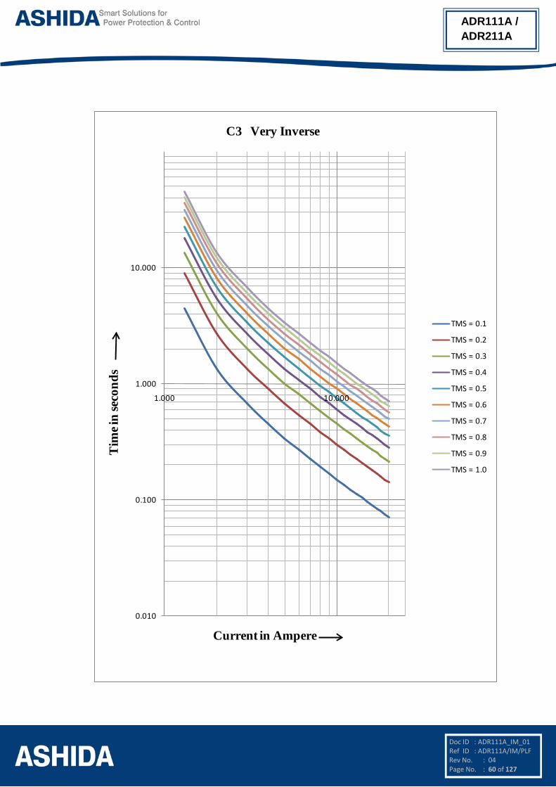
4.5 IDMT Characteristics ADR111A/ ADR211A relay provides following inverse time over current characteristics
• Normal Inverse 1 Curve (C1) for 3s
• Normal Inverse 2 Curve (C2) for 1.3s
• Very Inverse Curve (C3)
• Extremely Inverse Curve (C4)
• Extremely Inverse Curve (C4A) as per EE Relays
• Long time Inverse Curve (C5)
• Definite time Over current (C6)
The over current function is programmable as per IDMT characteristic based on IEC
standards. The inverse time delay is calculated with the following mathematical formula:
For IEC Inverse Curve For Extremely Inverse C4A Curve as per EE relays
t = K* a
IIref
b
– 1
t = K* a
IIref
b
– 1 * 1.3
+ 0.22
Where
t = operation time
a = constant
I = Input current
Iref = Current threshold setting
b = Constant
K = Time multiplier setting
Curve Type Description a b C1 Normal Inverse 1 0.14 0.02 C2 Normal Inverse 2 0.06 0.02 C3 Very Inverse 13.5 1 C4 Extremely inverse 80 2
C4A Extremely Inverse (C4A) as per EE Relays
80 2.2
C5 Long Time Inverse 120 1 C6 Definite Time - -

Doc ID : ADR111A_IM_01 Ref ID : ADR111A/IM/PLF Rev No. : 04 Page No. : 58 of 127
ADR111A / ADR211A
0.100
1.000
10.000
100.000
1.000 10.000
TMS = 0.1
TMS = 0.2
TMS = 0.3
TMS = 0.4
TMS = 0.5
TMS = 0.6
TMS = 0.7
TMS = 0.8
TMS = 0.9
TMS = 1.0
C1 Normal Inverse_1
Current in Ampere
Tim
e in
seco
nds

Doc ID : ADR111A_IM_01 Ref ID : ADR111A/IM/PLF Rev No. : 04 Page No. : 59 of 127
ADR111A / ADR211A
0.0
0.1
1.0
10.0
1.0 10.0
TMS = 0.1
TMS = 0.2
TMS = 0.3
TMS = 0.4
TMS = 0.5
TMS = 0.6
TMS = 0.7
TMS = 0.8
TMS = 0.9
TMS = 1.0
C2 Normal Inverse_2T
ime i
n se
cond
s
Current in Ampere
Doc ID : ADR111A_IM_01 Ref ID : ADR111A/IM/PLF Rev No. : 04 Page No. : 60 of 127
ADR111A / ADR211A
0.010
0.100
1.000
10.000
1.000 10.000
TMS = 0.1
TMS = 0.2
TMS = 0.3
TMS = 0.4
TMS = 0.5
TMS = 0.6
TMS = 0.7
TMS = 0.8
TMS = 0.9
TMS = 1.0
C3 Very Inverse
Current in Ampere
Tim
e in
seco
nds

Doc ID : ADR111A_IM_01 Ref ID : ADR111A/IM/PLF Rev No. : 04 Page No. : 61 of 127
ADR111A / ADR211A
0.010
0.100
1.000
10.000
100.000
1.000 10.000
TMS = 0.1
TMS = 0.2
TMS = 0.3
TMS = 0.4
TMS = 0.5
TMS = 0.6
TMS = 0.7
TMS = 0.8
TMS = 0.9
TMS = 1.0
C4 Extremely Inverse
Current in Ampere
Tim
e in
seco
nds

Doc ID : ADR111A_IM_01 Ref ID : ADR111A/IM/PLF Rev No. : 04 Page No. : 62 of 127
ADR111A / ADR211A
0.010
0.100
1.000
10.000
1.000 10.000
TMS = 0.1
TMS = 0.2
TMS = 0.3
TMS = 0.4
TMS = 0.5
TMS = 0.6
TMS = 0.7
TMS = 0.8
TMS = 0.9
TMS = 1.0
C4A Extremely Inverse As per EE Relay
Current in Ampere
Tim
e in
seco
nds

Doc ID : ADR111A_IM_01 Ref ID : ADR111A/IM/PLF Rev No. : 04 Page No. : 63 of 127
ADR111A / ADR211A
0.100
1.000
10.000
100.000
1000.000
1.000 10.000
TMS = 0.1
TMS = 0.2
TMS = 0.3
TMS = 0.4
TMS = 0.5
TMS = 0.6
TMS = 0.7
TMS = 0.8
TMS = 0.9
TMS = 1.0
C5 Long Time Inverse
Current in Ampere
Tim
e in
seco
nds

Page intentionally Left Blank

Doc ID : ADR111A_IM_01 Ref ID : ADR111A/IM/MS Rev No. : 04 Page No. : 65 of 127
ADR111A / ADR211A
Section 5
Metering Section

Doc ID : ADR111A_IM_01 Ref ID : ADR111A/IM/MS Rev No. : 04 Page No. : 66 of 127
ADR111A / ADR211A
Contents 5 MEASUREMENT SHEET 67
5.1 Measurement 67

Doc ID : ADR111A_IM_01 Ref ID : ADR111A/IM/MS Rev No. : 04 Page No. : 67 of 127
ADR111A / ADR211A
5 MEASUREMENT SHEET
5.1 Measurement Measurement window displays the value of Primary Current and Secondary current based
on the power system network.
Parameter Unit Description
I =0000.00 A Primary current
i =0000.00 A Secondary current

Page intentionally Left Blank

Doc ID : ADR111A_IM_01
Ref ID : ADR111A/IM/SS
Rev No. : 04
Page No. : 69 of 127
ADR111A / ADR211A
Section 6
Setting Sheet

Doc ID : ADR111A_IM_01
Ref ID : ADR111A/IM/SS
Rev No. : 04
Page No. : 70 of 127
ADR111A / ADR211A
Contents
6 SETTING SHEET 71
6.1 Relay Settings 71
6.2 Date and Time setting 72

Doc ID : ADR111A_IM_01
Ref ID : ADR111A/IM/SS
Rev No. : 04
Page No. : 71 of 127
ADR111A / ADR211A
6 SETTING SHEET
6.1 Relay Settings
Sr. No Parameter Defaults setting Setting / Ranges
1. Password 0000 0000 – 9999
This setting specifies to enter the set password
2. New Password 0000 0000 – 9999
This setting specifies to set the new password
3. Unit ID 001 001 – 250 in step of 1
This cell sets the unique address for the relay such that only one relay is accessed by master station software.
4. I> 100% 5% – 250% in step of 1%
This setting determines Pick-up setting for first stage (IDMT/DT) over current element.
5. I> TMS 1.00 0.01 – 1.50 in steps of 0.005
This setting for the time multiplier setting to adjust the operating time of the IDMT characteristic.
6. I>> 100% 50% – 3000% in step of 1%
This setting determines Pick-up setting for second stage (Inst/DT) over current element.
7. I> Curve C1
Normal Inverse 1 (C1)/ Normal Inverse 2 (C2)/ Very Inverse (C3)/ Extremely Inverse (C4)/ Extremely Inverse (C4A)/ Long Time Inverse (C5)/ Definite Time (C6)
This setting is used to select the IDMT curves for the various applications.
8. C6 Time 0 s 0 – 99.9 s in step of 0.1 s
This setting is used to set the time-delay for the Definite Time (DT) setting if selected for first stage over current element.
9. I>> Delay 1.00 s 0.00 – 10s in steps of 0.01s
This setting is used to set the time-delay for the setting for second stage over current element.
10. BF Delay 050 000 – 800 ms in step of 50 ms
This setting is used to set the time-delay for the CBF trip.
11. CT Secondary 1 A 1 A/5 A
This setting is used to set the CT Secondary
12. CT Primary 10 A 10 – 5000A in step of 1A
This setting is used to set the CT Primary.
13. Trip Cont 1 001 – 002 (1=SR, 2=HR)
This setting specifies to Trip contact can be set to Manual/Hand reset (HR) or Self reset (SR)
14. BF Cont 1 001 – 002 (1=SR, 2=HR)
This setting specifies to BF contact can be set to Manual/Hand reset (HR) or Self reset (SR)
15. Com Port FRONT FRONT/REAR
This setting specifies to select communication port for 103 communications.
16. Parity None None/Even/Odd

Doc ID : ADR111A_IM_01
Ref ID : ADR111A/IM/SS
Rev No. : 04
Page No. : 72 of 127
ADR111A / ADR211A
This setting is used to set parity. It is important that both relay and master station are set with the same parity setting.
17. Baud Rate 9600 2400/ 4800/ 9600/ 14400/ 19200
This setting is used to set Baud rate. It is important that both relay and master station are set with the same Baud rate setting.
18. Hrm. Rst. 10 00 – 80% in step of 5%
This setting is specify the 2nd Harm Threshold value, if the level of 2nd harmonic exceeds the setting, the over current protection will be blocked.
6.2 Date and Time setting
Sr. No Parameter Defaults setting Settings / Ranges
1. SET Hours 00 00 – 23 Hrs in step 1.
Hour setting needed when relay is not connected to SCADA system
2. SET Minutes 00 00 – 59 Mins in step 1.
Minutes setting needed when relay is not connected to SCADA system
3. SET Seconds 00 00 – 59 Sec. in step 1.
Seconds setting needed when relay is not connected to SCADA system
4. SET Date 01 01 – 31 Days in step of 1.
Date needed when relay is not connected to SCADA system
5. SET Month 01 01 – 12 Months in step of 1.
Month needed when relay is not connected to SCADA system
6. SET Year 01 00 – 99 Years in step of 1.
Year needed when relay is not connected to SCADA system

Page intentionally Left Blank

Doc ID : ADR111A_IM_01 Ref ID : ADR111A/IM/CS Rev No. : 04 Page No. : 74 of 127
ADR111A / ADR211A
Section 7
Communication
(Applicable to ADR211A Only)

Doc ID : ADR111A_IM_01 Ref ID : ADR111A/IM/CS Rev No. : 04 Page No. : 75 of 127
ADR111A / ADR211A
Contents 7 SCADA COMMUNICATIONS 76 7.1 MODBUS 76 7.1.1 MODBUS Protocol Map 76 7.1.1.1 Function Codes supported: 76 7.1.1.2 Exception Codes generated in case of an error: 77 7.2 IEC60-870-5-103 80 7.3 Physical Connection and Link Layer 80 7.4 Initialisation 80 7.5 Time Synchronisation 81 7.6 Spontaneous Events 81 7.7 General Interrogation (GI) 81 7.8 Cyclic Measurements 81 7.9 Commands 81 7.10 Configuration 82 7.11 IEC-103 Protocol Mapping 82

Doc ID : ADR111A_IM_01 Ref ID : ADR111A/IM/CS Rev No. : 04 Page No. : 76 of 127
ADR111A / ADR211A
7 SCADA COMMUNICATIONS 7.1 MODBUS
This section describes how the MODBUS standard is applied to the RT platform. It is not a
description of the standard itself. The level at which this section is written assumes that the
reader is already familiar with the MODBUS standard.
The MODBUS protocol is a master/slave protocol, defined and administered by the
MODBUS Organization. For further information on MODBUS and the protocol specifications
please see the Modbus web site (www.modbus.org).
Overview: Physical Connection and Link Layer
For connecting on MODBUS use:
Rear serial port - for permanent SCADA connection via RS422/ RS485
The MODBUS interface uses ‘RTU’ mode communication rather than ‘ASCII’ mode as this
provides more efficient use of the communication bandwidth. This mode of communication is
defined by the MODBUS standard.
The IED address and baud rate can be selected using the relay front panel.
When using a serial interface, the data format is: 1 start bit, 8 data bits, 1 stop bit (a total of
10 bits per character).
7.1.1 MODBUS Protocol Map 7.1.1.1 Function Codes supported:
Code Function Name Addresses starts with
02 Read Input Status 1x addresses
03 Read Holding Registers 4x addresses
04 Read Input Registers 3x addresses
05 Force Single Coil 0x addresses
16 Preset Multiple Registers 4x addresses

Doc ID : ADR111A_IM_01 Ref ID : ADR111A/IM/CS Rev No. : 04 Page No. : 77 of 127
ADR111A / ADR211A
7.1.1.2 Exception Codes generated in case of an error:
Code MODBUS Response
Name
Product interpretation
01 Illegal Function Code The function code received in query is not supported by the IED.
02 Illegal Data Address The start address received in the query is not an allowable value.
NOTE: If the start address received is correct but the range includes
unsupported address this error is produced.
NOTE: The addresses of the MODBUS registers start from 1 and the user may have to subtract 1
from the addresses, depending upon the configuration of the Master station configuration.
Sr.
No.
Function
Code
Register No. of
Regs
Format Reg.
Type
Address
Map
1 Product Information
03
Manufacturer
Name
10 20-Bytes
ASCII
R 4x00001 –
4x00010
Relay Name 10 20-Bytes
ASCII
R 4x00011 –
4x00020
Model 10 20-Bytes
ASCII
R 4x00021 –
4x00030
Version 10 20-Bytes
ASCII
R 4x00031 –
4x00040
Sr.
No.
Function
Code
Register No. of
Regs
Format Reg.
Type
Address
Map
2 Relay
Configuration 03
Num Status (s) 1 16 bit R 4x00258
Num Controls (c) 1 16 bit R 4x00259
Num Parameters
(p)
1 16 bit R 4x00260
Num Faults (f) 1 16 bit R 4x00261
Inverted IEC 870-5-4 CP56Time2a Format

Doc ID : ADR111A_IM_01 Ref ID : ADR111A/IM/CS Rev No. : 04 Page No. : 78 of 127
ADR111A / ADR211A
Time Synchronization – For ASHIDA RTV2 IEDs on Modbus, time synchronization is possible via a broad cast
command to 800H (4x02049 through 4x02052). The format is Inverted IEC 870-5-4 CP56Time2a.
Words 7 6 5 4 3 2 1 0 7 6 5 4 3 2 1 0
1 0 0 0 0 0 0 0 0 Year 00….99
2 0 0 0 0 Month
Day of
Week Day of Month 1...12 1…7 1…31
3 Hours Iv0 Minutes 0….23 0….59
4 Milliseconds Hi Milliseconds Lo
0…..59999 (second +
mill seconds)
Su (=0 standard, =1 Summer Time)
iv (=0 valid, =1 nonvalid or nonsynchronized system case)
First Day of week is Monday
Sr.
No.
Function
Code
Register No. of
Regs
Format Reg.
Type
Address
Map
3 Time
Synchronization
(Unicast/Broadcast)
03/16
Year 1 16 bit R/W 4x02049
Month- Day 1 16 bit R/W 4x02050
Hour, Min 1 16 bit R/W 4x02051
Milliseconds 1 16 bit R/W 4x02052
Sr.
No.
Function
Code
Register No. of
Regs
Format Reg.
Type
Address
Map
4 Status and Logical Status
02
Relay Error 1 1 bit R 1x32773
Test 1 1 bit R 1x32774
General Start 1 1 bit R 1x32777
Start I> 1 1 bit R 1x32778
Start I>> 1 1 bit R 1x32779
General Trip 1 1 bit R 1x32780

Doc ID : ADR111A_IM_01 Ref ID : ADR111A/IM/CS Rev No. : 04 Page No. : 79 of 127
ADR111A / ADR211A
Breaker Fail 1 1 bit R 1x32782
Trip I> 1 1 bit R 1x32783
Trip I>> 1 1 bit R 1x32784
Sr.
No.
Function
Code
Register No. of
Regs
Format Reg.
Type
Address
Map
5 Status and Logical Status
05
Trip 1 16 bit W 0x33025
LED Reset 1 16 bit W 0x33026
Sr.
No.
Function
Code
Register No. of
Regs
Format Reg.
Type
Address
Map
6 Parameters 04
I 2 32 bit Float
R 3x33281-3x33282

Doc ID : ADR111A_IM_01 Ref ID : ADR111A/IM/CS Rev No. : 04 Page No. : 80 of 127
ADR111A / ADR211A
7.2 IEC60-870-5-103 The specification IEC 60870-5-103 (Tele control Equipment and Systems Part 5 Section 103:
Transmission Protocols), defines the use of standards IEC 60870-5-1 to IEC 60870-5-5,
which were designed for communication with protection equipment.
This section describes how the IEC 60870-5-103 standard is applied to the ADR211A Relay.
It is not a description of the standard itself. The level at which this section is written assumes
that the reader is already familiar with the IEC 60870-5-103 standard.
This section should provide sufficient detail to enable understanding of the standard at a
level required by most users.
The IEC 60870-5-103 interface is a master/slave interface with the device as the slave
device. The device conforms to compatibility level 2, as defined in the IEC 60870-5-
103.standard.
The following IEC 60870-5-103 facilities are supported by this interface:
• Initialization (reset)
• Time synchronisation
• Event record extraction
• General interrogation
• Cyclic measurements
• General commands
7.3 Physical Connection and Link Layer For connecting on IEC 60870-5-103 there are two options:
• Front USB Port.
• Rear serial port - for permanent SCADA connection via RS422/ RS485. The IED address, Parity and Baud rate can be selected using the relay front panel.
7.4 Initialisation Whenever the device has been powered up, or if the communication parameters have been
changed, a reset command is required to initialize the communications. The device will
respond to either of the two reset commands; Reset CU or Reset FCB (Communication Unit
or Frame Count Bit). The difference between the two commands is that the Reset CU
command will clear any unsent messages in the transmit buffer, whereas the Reset FCB
command does not delete any messages.
The device will respond to the reset command with an identification message ASDU 5. The
Cause of Transmission (COT) of this response will be either Reset CU or Reset FCB
depending on the nature of the reset command.
The relay will also produce a power up event, when the relay is powered up.

Doc ID : ADR111A_IM_01 Ref ID : ADR111A/IM/CS Rev No. : 04 Page No. : 81 of 127
ADR111A / ADR211A
7.5 Time Synchronisation The time and date can be set using the time synchronisation feature of the IEC 60870-5-103
protocol. The device will correct the transmission delay depending on communication speed.
For this, transmission time, required for the time synchronization frame from the Master to
IED, considering current baud rate is added in the received time.
The device will correct the transmission delay depending on baud rate. If the time
synchronisation message is sent as a send/confirm message then the device will respond
with a confirm message. A time synchronisation Class 1 event will be generated/produced
whether the time-synchronisation message is sent as a send confirm or a broadcast
(send/no reply) message.
7.6 Spontaneous Events Events are categorized using the following information:
Function type
Information Number
The IEC 60870-5-103 profile in the Menu Database contains a complete listing of all events
produced by the device.
7.7 General Interrogation (GI) The GI request can be used to read the status of the device, the function numbers, and
information numbers that will be returned during the GI cycle. These are shown in the IEC
60870-5-103 profile in the Menu Database.
7.8 Cyclic Measurements The device will produce measured values using ASDU244. ASDU244 will be reported with
information number 0. These frames are reported alternately. This can be read from the
device using a Class 2 poll. For every query the current online data is reported.
7.9 Commands
A list of the supported commands is contained in the Menu database. The device will
respond to other commands with ASDU 1, with a cause of transmission (COT) indicating
‘negative acknowledgement’.

Doc ID : ADR111A_IM_01 Ref ID : ADR111A/IM/CS Rev No. : 04 Page No. : 82 of 127
ADR111A / ADR211A
7.10 Configuration To configure the IED for this protocol, please see the Configuration chapter.
7.11 IEC-103 Protocol Mapping Sr. No. INF Description GI TYP COT FUN
1 Semantics of INFORMATION NUMBER : System Functions in monitor direction
0 End of general interrogation - 8 10 255
0 Time synchronization - 6 8 255
2 Reset FCB - 5 3 160
3 Reset CU - 5 4 160
4 Start/Restart - 5 5 160
5 Power on - 5 6 160
Note: X under GI heading means DI Status is included in General Interrogation response.
Sr. No. INF Description GI TYP COT FUN
2 Semantics of INFORMATION NUMBER : Status & Fault indications in monitor direction
19 Trip LED X 1 1,7,9,11,12,20,21 160
22 Local parameter setting X 1 9,11,12 160
84 General Start X 2 1,7,9 160
117 Start I> X 2 1,7,9 126
103 Start I>> X 2 1,7,9 126
68 General Trip - 2 1,7 160
90 Trip I> - 2 1,7 160
91 Trip I>> - 2 1,7 160
85 50 BF x 2 1,7 160
21 Test Trip - 2 1,7 127
Sr. No. INF Description GI TYP COT FUN
3 Semantics of INFORMATION NUMBER : Measurands in monitor direction
148 I in MEA format - 9 2, 7 160
NOTE: The measurands transmitted by the relay are sent as a proportion of 1.2 times of the rated value

Doc ID : ADR111A_IM_01 Ref ID : ADR111A/IM/CS Rev No. : 04 Page No. : 83 of 127
ADR111A / ADR211A
Sr. No. INF Description GI TYP COT FUN
4 Semantics of INFORMATION NUMBER : System Functions in control direction
0 Initialization of general interrogation
- 7 9 255
0 Time synchronization - 6 8 255
Sr. No. INF Description GI TYP COT FUN
5 Semantics of INFORMATION NUMBER : General commands in control direction
19 LED Reset ON 20 20 160
124 Trip relay ON 20 20 127

Page intentionally Left Blank

Doc ID : ADR111A_IM_01 Ref ID : ADR111A/IM/UG Rev No. : 04 Page No. : 85 of 127
ADR111A / ADR211A
Section 8
User Guide

Doc ID : ADR111A_IM_01 Ref ID : ADR111A/IM/UG Rev No. : 04 Page No. : 86 of 127
ADR111A / ADR211A
Contents
8 USER GUIDE 87 8.1 USER INTERFACE 88 8.1.1 LCD Display 88 8.1.2 Touch Keys 88 8.1.3 LEDs 89 8.1.4 RS422 / RS485 Port (For ADR211A) 89 8.1.5 USB Port (For ADR211A) 89 8.2 MENUS 90 8.2.1 Default Display 90 8.2.2 Main Menu Details 90 8.2.3 MEASUREMENT 92 8.2.3.1 To View – MEASUREMENT 92 8.2.4 Relay Settings 93 8.2.4.1 To Set – Relay Settings 93 8.2.4.2 To View – Relay Settings 97 8.2.5 Trip Test 99 8.2.6 Fault 1 99 8.2.6.1 To View – Fault 1 99 8.2.7 To View Error Log 100 8.2.8 STATUS 101 8.2.8.1 To View – STATUS 101 8.2.9 DATE AND TIME SETTINGS 101 8.2.9.1 To Set – DATE AND TIME Settings 101 8.2.9.2 To View – DATE AND TIME Settings 103
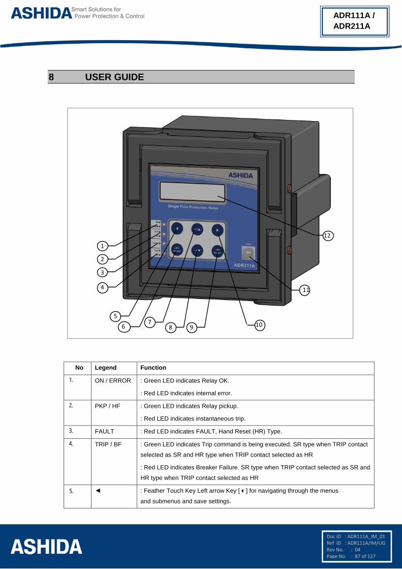
Doc ID : ADR111A_IM_01 Ref ID : ADR111A/IM/UG Rev No. : 04 Page No. : 87 of 127
ADR111A / ADR211A
8 USER GUIDE
5
4
3
2
1
67
8 109
12
11
No Legend Function
1. ON / ERROR : Green LED indicates Relay OK.
: Red LED indicates internal error.
2. PKP / HF : Green LED indicates Relay pickup.
: Red LED indicates instantaneous trip.
3. FAULT : Red LED indicates FAULT, Hand Reset (HR) Type.
4. TRIP / BF : Green LED indicates Trip command is being executed. SR type when TRIP contact
selected as SR and HR type when TRIP contact selected as HR
: Red LED indicates Breaker Failure. SR type when TRIP contact selected as SR and
HR type when TRIP contact selected as HR
5. : Feather Touch Key Left arrow Key [] for navigating through the menus
and submenus and save settings.
Doc ID : ADR111A_IM_01 Ref ID : ADR111A/IM/UG Rev No. : 04 Page No. : 88 of 127
ADR111A / ADR211A
No Legend Function
6. LED RESET : Feather Touch Key LED RESET to Reset LED and HR Type Output contact
7. + / : Feather Touch Key [ + ] Plus to INCREMENT the values &
[] to SCROLL the Main Menu up.
8. - / : Feather Touch Key [ - ] Minus to 'DECREMENT' the values &
[] to SCROLL the Main Menu down.
9. HW RESET : Feather Touch Key for HW RESET is provided for Hardware Reset. This key is
interlock with LED RESET key.
10. : Feather Touch Key [] to VIEW the settings and to navigate through the menus
and submenus.
11. USB : USB port for serial communication. (For ADR211A only)
12. LCD Display : 16 x 2 char. LCD display to observe settings and parameters of the relay.
8.1 USER INTERFACE 8.1.1 LCD Display
Back-lit LCD display 16 x 2 characters is provided for the parameter and setting display,
and for easy viewing of measurement, setting, fault records, date & time and error
message. Back-lit will automatically switch OFF if any key is not pressed for more than
100sec. Back-lit is also automatically turned ON when any tripping occurs.
8.1.2 Touch Keys The function of relay is controlled by the following keys provided on the Front Plate:
() Left Arrow: Left Arrow key () is used to navigate through the menus and SAVE
settings.
(+ / ) Plus / Up Arrow: (+) Plus is used to increment the setting value in the display. The
() Up Arrow is used to scroll the menu in UP direction.
() Right Arrow: The Right Arrow key is used to VIEW the settings and to navigate
through the menus.
LED RESET: The Key for Reset LED and HR type Output contact
(- / ) Minus / Down Arrow: (-) Minus is used to decrement the setting value in the
display. The () Down Arrow is used to scroll the menu in DOWN direction.
HW RESET: The ‘HW RESET’ key is not required in normal operation but it is used to
reset total hardware of relay. This key is interlocked with LED RESET key. This is
normally required during firmware update of relay.

Doc ID : ADR111A_IM_01 Ref ID : ADR111A/IM/UG Rev No. : 04 Page No. : 89 of 127
ADR111A / ADR211A
NOTE: At the time of setting if changes are not carried within 100s then the display will reset itself
and return to the main menu.
8.1.3 LEDs The ADR111A/ ADR211A Relay is having 4 dual colour LED’s of high intensity for easy
identification of type of fault for easy user interface.
No LED Function
1. ON /
ERROR
: Green LED indicates Relay OK.
: Red LED indicates internal error.
2. PKP /
HF
: Green LED indicates Relay pickup.
: Red LED indicates instantaneous trip.
3. FAULT : Red LED indicates FAULT, Hand Reset (HR) Type.
4. TRIP /
BF
: Green LED indicates Trip command is being executed.
: Red LED indicates Breaker Failure.
8.1.4 RS422 / RS485 Port (For ADR211A) RS422 / RS485 Port is provided at the rear side of relay for permanent SCADA
connectivity. Using RS422 / RS485 port the Fault data, Auxiliary Status and online
measurement can be viewed.
Note: The RS422 4 wire (Tx+, Tx-, Rx+, Rx-) communication port can be used as RS485 2 wire
(D+, D-) by shorting terminal A5 & A7 used as D+ and A6 & A8 used as D-.
8.1.5 USB Port (For ADR211A) The USB port includes a USB full-speed function controller, USB transceiver, oscillator,
EEPROM, and asynchronous serial data bus (UART). No other external USB
components are required.
The USB Communication port is provided on front panel of relay. This is very useful for
downloading relay data and analysis it.
For proper operation the user must select the proper communication port in the Relay
Setting.

Doc ID : ADR111A_IM_01 Ref ID : ADR111A/IM/UG Rev No. : 04 Page No. : 90 of 127
ADR111A / ADR211A
8.2 MENUS 8.2.1 Default Display
After the Power ON or when the H/W. RESET + LED RESET key is pressed, the relay will
display the following message.
Ashida Digital
Relay
This window will flash momentarily showing the following.
Relay Name : Ashida Digital Relay
Then the control will automatically move to next option.
ADR211A V–02.00
Unit ID = 001
This window will flash momentarily showing the following.
Relay Type: ADR211A_V – 02.00; Unit ID 001
Then the control will automatically move to next option.
I = 0000A
This window shows actual Primary load current as per the CT
Primary selection.
8.2.2 Main Menu Details
I = 0000A
This window shows actual Primary load current as per the CT
Primary selection.
Press the Right arrow key () to move to the next option.
i = 000.00
This window shows actual Secondary load current as per the
CT Secondary selection.
Press the Right arrow key () to move to the next option.
Measurement
The relay will display “Measurement” in Main Menu.
Press the Plus / up arrow key (+ /) to move to the next option.
Relay Settings
Password protected window for “Relay Settings’’ setting i.e.
New Password, Unit ID, I>, I> TMS, I>>, I> Curve, I>C6 Time,
I>> Delay, CT Sec., CT Primary, Trip Cont, BF Cont., BF Delay,
Com Port, Parity, Baud Rate and Hrm Rst.

Doc ID : ADR111A_IM_01 Ref ID : ADR111A/IM/UG Rev No. : 04 Page No. : 91 of 127
ADR111A / ADR211A
Press the Plus / up arrow key (+ /) to move to the next option.
Trip Test
To apply “Trip Test”
Press the Plus / Up arrow key (+ /) to move to the next option.
Fault 1
To view “Fault 1”
Press the Plus / Up arrow key (+ /) to move to the next option.
Fault 2
To view “Fault 2”
Press the Plus / Up arrow key (+ /) to move to the next option.
Fault 3
To view “Fault 3”
Press the Plus / Up arrow key (+ /) to move to the next option.
Fault 4
To view “Fault 4”
Press the Plus / Up arrow key (+ /) to move to the next option.
Fault 5
To view “ Fault 5”
Press the Plus / Up arrow key (+ /) to move to the next option.
Error Log
To view “Error Log”
Press the Plus / Up arrow key (+ /) to move to the next option.
Status
To view “Status”
Press the Plus / Up arrow key (+ /) to move to the next option.

Doc ID : ADR111A_IM_01 Ref ID : ADR111A/IM/UG Rev No. : 04 Page No. : 92 of 127
ADR111A / ADR211A
DATE / TIME
Password protected window for “DATE / TIME” setting i.e. Set
Hour, Set Minute, Set Second, Set Date, Set Month and Set
Year.
Press the Plus / Up arrow key (+ /) to move to the next option.
MEASUREMENT
This window shows the first window of Main Menu.
8.2.3 MEASUREMENT
8.2.3.1 To View – MEASUREMENT
MEASUREMENT
This menu is to view CT Primary and Secondary current as per
selection,
Press the Right arrow key () to move to the next option.
I = 0000A
This window shows actual Primary load current as per the CT
Primary selection.
Press the Right arrow key () to move to the next option.
i = 000.00
This window shows actual Secondary load current as per the
CT Secondary selection.
Press the Right arrow key () to move to the next option.
MEASUREMENTS

Doc ID : ADR111A_IM_01 Ref ID : ADR111A/IM/UG Rev No. : 04 Page No. : 93 of 127
ADR111A / ADR211A
8.2.4 Relay Settings
8.2.4.1 To Set – Relay Settings
Relay Settings
Password protected window for “Relay Settings’’ setting i.e.
New Password, Unit ID, I>, I> TMS, I>>, I> Curve, I>C6 Time,
I>> Delay, BF Delay, CT Sec., CT Primary, Trip Cont, BF Cont.,
Com Port, Parity, Baud Rate and Hrm Rst.
Press the left arrow Key () to move to the next option..
Password = 0000
Use Inr / Dec
Editable setting
Enter the previously set password, by using the up arrow key
(+ /) or the down arrow key (- /).
The setting range is from 0000 to 9999 in steps of 1.
Note: Default password setting is ‘0000’
Press the left arrow Key () to move to the next option.
Password = 000
New Password
Editable setting
By using the Plus / Up arrow key (+ /) or the Minus / Down
arrow key (- /) the desired New Password can be set.
The setting range is from 0000 to 9999 in steps of 1.
Press the left arrow Key () to move to the next option.
Unit ID = 001
Editable Setting
By using the Plus / Up arrow key (+ /) or the Minus / Down
arrow key (- /) the desired Unit ID can be set.
The unit address will vary from 001 to 250, which means total
249 devices can be connected to single computer. The 250
address is reserved for special command. These settings are
required to communicate with the SCADA computer.
Press the left arrow Key () to move to the next option.
I> = 100
Range 5 – 250%
Editable Setting
By using the Plus / Up arrow key (+ /) or the Minus / Down
arrow key (- /) the desired I> can be set.

Doc ID : ADR111A_IM_01 Ref ID : ADR111A/IM/UG Rev No. : 04 Page No. : 94 of 127
ADR111A / ADR211A
The setting range is 5 to 250% in steps of 1%.
Press the left arrow Key () to move to the next option.
I> TMS = x1.000
Range x0.01 – 1.50
Editable Setting
By using the Plus / Up arrow key (+ /) or the Minus / Down
arrow key (- /) the desired I> TMS (Time Multiplier Settings)
can be set.
The setting range is x0.01 to 1.50 in steps of 0.005
Press the left arrow Key () to move to the next option.
I>> = 0100
Range 50 – 3000%
Editable Setting
By using the Plus / Up arrow key (+ /) or the Minus / Down
arrow key (- /) the desired I>> can be set.
The setting range is 50% to 3000% in steps of 1%
Press the left arrow key () to move to the next option.
I> Curve = C1
Range C1 – C6
Editable Setting
By using the Plus / Up arrow key (+ /) or the Minus / Down
arrow key (- /) the desired I> Curve (IDMT Curve) can be
selected.
Seven different types of curves are provided C1 to C6. When
the given value is C1 curve 1 is selected and when the given
value is C2 curve 2 is selected. In similar manner any desired
curve can be selected as C1 to C6 corresponds
C1 = Normal Inverse 1 (10 Times 3.0 sec)
C2 = Normal Inverse 2 (10 Times 1.3 sec)
C3 = Very Inverse (10 Times 1.5 sec)
C4 = Extremely Inverse (10 Times 0.8 sec)
C4A = Extremely Inverse (10 Times 0.6 sec)
C5 = Long Time Inverse (10 Times 13.3 sec)
C6 = Definite Time (Inst. to 99.9 sec)
Press the left arrow Key () to move to the next option.

Doc ID : ADR111A_IM_01 Ref ID : ADR111A/IM/UG Rev No. : 04 Page No. : 95 of 127
ADR111A / ADR211A
I>C6 Time = 00.1
Range 00 – 99.9 S
Editable Setting
By using the Plus / Up arrow key (+ /) or the Minus / Down
arrow key (- /) the desired I>C6 Time (Definite Time Delay)
can be set.
The setting range is 00 to 99.9 S in steps of 0.1 S. This setting
is effective only when C6 curve is selected.
Press the left arrow Key () to move to the next option.
I>> Delay = 00.05
Range 0 – 10.00 S
Editable Setting
By using the Plus / Up arrow key (+ /) or the Minus / Down
arrow key (- /) the desired I>> Delay can be set.
The setting range is 0 to 10.00 S in steps of 0.01 S.
Press the left arrow Key () to move to the next option.
BF Delay = 100
Range 00 – 800 ms
Editable Setting
By using the Plus / Up arrow key (+ /) or the Minus / Down
arrow key (- /) the desired BF Delay (Breaker Fail) can be
set.
The setting range is 00 to 800 ms in steps of 50 ms. The 000
means bypass this feature.
Press the left arrow Key () to move to the next option.
CT Sec. = 001
1 = 1A, 2 = 5A
Editable Setting
By using the Plus / Up arrow key (+ /) or the Minus / Down
arrow key (- /) the desired CT Secondary can be selected.
i.e. 1 or 2. In which, 1 corresponds with 1 Amp. and 2
correspond with 5 Amp respectively.
Press the left arrow Key () to move to the next option.
CT Primary = 0010
Range 10 – 5000
Editable Setting
By using the Plus / Up arrow key (+ /) or the Minus / Down
arrow key (- /) the desired CT Primary can be set.
The Setting Range is from 10 to 5000A in steps of 1A. (For
example suppose CT Ratio is 500/1A then you have to select

Doc ID : ADR111A_IM_01 Ref ID : ADR111A/IM/UG Rev No. : 04 Page No. : 96 of 127
ADR111A / ADR211A
CT Pri =500 so that when 1A current flows into relay circuit, in
measurement window it will show you 500A).
Press the left arrow Key () to move to the next option.
Trip Cont = 002
SR = 1 HR = 2
Editable Setting
By using the Plus / Up arrow key (+ /) or the Minus / Down
arrow key (- /) the desired Trip Contact can be selected. i.e.
1 or 2. In which, 1 corresponds with SR (Self-Reset) and 2
correspond with HR (Hand-Reset) respectively.
Press the left arrow Key () to move to the next option.
BF Cont = 002
SR = 1 HR = 2
Editable Setting
By using the Plus / Up arrow key (+ /) or the Minus / Down
arrow key (- /) the desired BF Contact can be selected. i.e. 1
or 2. In which, 1 corresponds with SR (Self-Reset) and 2
correspond with HR (Hand-Reset) respectively.
Press the left arrow Key () to move to the next option.
Com Port = FRONT
FRONT/REAR
Editable Setting
By using the Plus / Up arrow key (+ /) or the Minus / Down
arrow key (- /) the desired Com Port can be set i.e. FRONT /
REAR
Press the left arrow Key () to move to the next option.
Parity = None
None/Even/Odd
Editable Setting
By using the Plus / Up arrow key (+ /) or the Minus / Down
arrow key (- /) the desired Parity can be set i.e. None / Even
/ Odd
Press the left arrow Key () to move to the next option.
Baud Rate = 003
Range 1 – 5
Editable Setting
By using the Plus / Up arrow key (+ /) or the Minus / Down
arrow key (- /) the desired Baud Rate can be set.
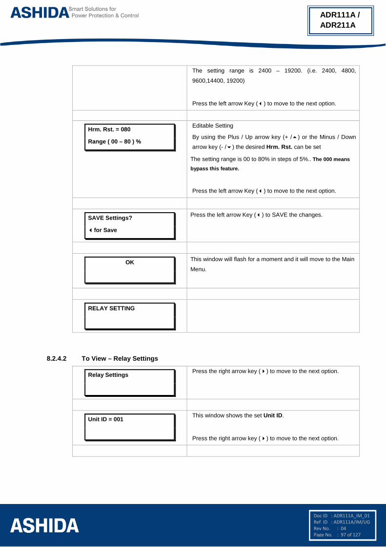
Doc ID : ADR111A_IM_01 Ref ID : ADR111A/IM/UG Rev No. : 04 Page No. : 97 of 127
ADR111A / ADR211A
The setting range is 2400 – 19200. (i.e. 2400, 4800,
9600,14400, 19200)
Press the left arrow Key () to move to the next option.
Hrm. Rst. = 080
Range ( 00 – 80 ) %
Editable Setting
By using the Plus / Up arrow key (+ /) or the Minus / Down
arrow key (- /) the desired Hrm. Rst. can be set
The setting range is 00 to 80% in steps of 5%.. The 000 means
bypass this feature.
Press the left arrow Key () to move to the next option.
SAVE Settings?
for Save
Press the left arrow Key () to SAVE the changes.
OK
This window will flash for a moment and it will move to the Main
Menu.
RELAY SETTING
8.2.4.2 To View – Relay Settings
Relay Settings
Press the right arrow key () to move to the next option.
Unit ID = 001
This window shows the set Unit ID.
Press the right arrow key () to move to the next option.

Doc ID : ADR111A_IM_01 Ref ID : ADR111A/IM/UG Rev No. : 04 Page No. : 98 of 127
ADR111A / ADR211A
I>100% t>1.000
I>>0100%
This window shows the set Current values.
Press the right arrow key () to move to the next option.
I>Normal Inv.1
This window shows the set Curve.
Press the right arrow key () to move to the next option.
I>C6 Time = 00.1
I>> Delay = 00.05
This window shows the set I> C6 Time and I>> Delay
Press the right arrow key () to move to the next option.
CT Sec. = 01A
CT Pri. = 0010A
This window shows the set CT Secondary and CT Primary.
Press the right arrow key () to move to the next option.
Trip Cont = HR
BF Cont = HR
This window shows the set Trip Cont and BF Cont.
Press the right arrow key () to move to the next option.
BF Delay = 100
Com Port = FRONT
This window shows the set BF Delay & Com Port.
Press the right arrow key () to move to the next option.
Parity = None
Baud Rate = 09600
This window shows the set Parity and Baud Rate
Press the right arrow key () to move to the next option.
Hrm. Rst. = 000%
This window shows the set Harmonic Restrain Function.
Press the right arrow key () to move to the Main Menu.
Relay Settings

Doc ID : ADR111A_IM_01 Ref ID : ADR111A/IM/UG Rev No. : 04 Page No. : 99 of 127
ADR111A / ADR211A
8.2.5 Trip Test
Trip Test
The password protected window for Trip Test.
Press the left arrow key () to move to the next option
Password = 0000
Use Inr / Dec
Editable setting
Enter the previously set password, by using the up arrow key
(+ /) or the down arrow key (- /).
Note: Default password setting is ‘0000’
Press the left arrow Key () to apply the Trip Test.
I>> : TC:0000
I> : T
This window will show High Fault, Trip Counter, IDMT Fault and Test Trip Flag.
Press the left arrow key () to move to the next option
FAULT 1
8.2.6 Fault 1
8.2.6.1 To View – Fault 1
FAULT 1
This menu is to view “Fault 1”
Press the Right arrow key () to move to the next option.
I>> : I TC:0000
I> : I BF T
This window will show High Fault, Trip Counter, IDMT Fault
and Breaker Fail or Test Trip indication.
Press the Right arrow key () to move to the next option.
I = 1000 A
i = 000.00A
This window will show Primary & Secondary Current measured
at the time of the fault.
Please note: If Fault current is ≤ 9999 then display will show
the current in Ampere i.e. 9999A and If Fault current is ≥ 10000
then display will show the current in Kilo Ampere i.e. 10.00K

Doc ID : ADR111A_IM_01 Ref ID : ADR111A/IM/UG Rev No. : 04 Page No. : 100 of 127
ADR111A / ADR211A
Press the Right arrow key () to move to the next option.
02/06/16
14:32:51:085
This window will show Date & Time of Fault.
Press the Right arrow key () to move to the Main Menu.
Fault 1
Note : Fault 2, Fault 3, Fault 4 and Fault 5 can be viewed in simillar manner
8.2.7 To View Error Log
Error Log
This menu is to view “Error Log”
Press the Right arrow key () to move to the next option.
Error Code : 0000
This window will show Error Code.
Press the Right arrow key () to move to the next option.
Error Log
The relay continuously keeps track on its internal hardware and the moment it detects any
failure of component, a message is displayed on LCD display. The type of error can be
checked by “Error Log” menu. This feature is very useful for giving pre information to
avoid mal operation.
Following are some of Error codes: -
Error Code Description
01 Setting Error
02 EEPROM Error
04 RTC Error
08 Crystal Error

Doc ID : ADR111A_IM_01 Ref ID : ADR111A/IM/UG Rev No. : 04 Page No. : 101 of 127
ADR111A / ADR211A
16 ADC Error
32 FRAM Error1
64 FRAM Error2
In case of ADC error relay will not work at all and will show directly ADC Error and relay
function will be locked.
8.2.8 STATUS
8.2.8.1 To View – STATUS
STATUS
This menu is to view “STATUS” i.e. Software Version and
Hardware Version.
Press the Right arrow key () to move to the next option.
SWV : 02.00
HWV : 02.00
This window will show Relay Software & Hardware Version.
Press the Right arrow key () to move to the next option.
STATUS
8.2.9 DATE AND TIME SETTINGS
8.2.9.1 To Set – DATE AND TIME Settings
DATE / TIME
Password protected window for “DATE / TIME” setting i.e. Set
Hour, Set Minute, Set Second, Set Date, Set Month, and Set
Year.
Press the left arrow Key () to move to the next option.
Password = 0000
Use Inr / Dec
Editable setting
Enter the previously set password, by using the up arrow key
(+ /) or the down arrow key (- /).
Note: Default password setting is ‘0000’
Press the left arrow Key () to move to the next option.

Doc ID : ADR111A_IM_01 Ref ID : ADR111A/IM/UG Rev No. : 04 Page No. : 102 of 127
ADR111A / ADR211A
SET Hour = 017
Range 0 – 23
Editable Setting
By using the Plus / Up arrow key (+ /) or the Minus / Down
arrow key (- /) the desired SET Hour can be set.
The setting range is from 00 to 23 in steps of 1.
Press the left arrow Key () to move to the next option.
SET Minute = 039
Range 0 – 59
Editable Setting
By using the Plus / Up arrow key (+ /) or the Minus / Down
arrow key (- /) the desired SET Minute can be set.
The setting range is from 00 to 59 in steps of 1.
Press the left arrow Key () to move to the next option.
SET Second = 040
Range 0 – 59
Editable Setting
By using the Plus / Up arrow key (+ /) or the Minus / Down
arrow key (- /) the desired SET Second can be set.
The setting range is from 00 to 59 in steps of 1.
Press the left arrow Key () to move to the next option.
SET Date = 002
Range 1 – 31
Editable Setting
By using the Plus / Up arrow key (+ /) or the Minus / Down
arrow key (- /) the desired SET Date can be set.
The setting range is from 1 to 31 in steps of 1.
Press the left arrow Key () to move to the next option.
SET Month = 006
Range 1 – 12
Editable Setting
By using the Plus / Up arrow key (+ /) or the Minus / Down
arrow key (- /) the desired SET Month can be set.
The setting range is from 1 to 12 in steps of 1.
Press the left arrow Key () to move to the next option.

Doc ID : ADR111A_IM_01 Ref ID : ADR111A/IM/UG Rev No. : 04 Page No. : 103 of 127
ADR111A / ADR211A
SET Year = 016
Range 00 – 99
Editable Setting
By using the Plus / Up arrow key (+ /) or the Minus / Down
arrow key (- /) the desired SET Year can be set.
The setting range is from 00 to 99 in steps of 1.
Press the left arrow Key () to move to the next option.
SAVE Settings?
Mode for Save
Press the left arrow Key () to move to the next option.
OK
This window will flash for a moment and it will move to the Main
Menu.
DATE / TIME
8.2.9.2 To View – DATE AND TIME Settings
DATE AND TIME
Press the Right arrow key () to move to the next option.
Time : 15:20:25
Date : 02/06/16
Press the Right arrow key () to return to the Main Menu.
DATE AND TIME

Page intentionally Left Blank

Doc ID : ADR111A_IM_01 Ref ID : ADR111A/IM/FC Rev No. : 04 Page No. : 105 of 127
ADR111A / ADR211A
Section 9
Flow Chart

Doc ID : ADR111A_IM_01 Ref ID : ADR111A/IM/FC Rev No. : 04 Page No. : 106 of 127
ADR111A / ADR211A
Contents 9 Flow Chart Overview 107
9.1 Main Menu 107 9.2 Flow Chart – Measurement 108 9.2.1 To View – Measurement 108 9.3 Flow Chart – Relay Setting 109 9.3.1 To Set – Relay Setting 109 9.3.2 To View – Relay Setting 110 9.4 Flow Chart – Trip Test 111 9.4.1 To Set – Trip Test 111 9.5 Flow Chart – Fault 1 112 9.5.1 To View – Fault 1 112 9.6 Flow Chart – Error Log 112 9.6.1 To View – Error Log 112 9.7 Flow Chart – Status 113 9.7.1 To View – Status 113 9.8 Flow Chart – Date and Time 114 9.8.1 To Set – Date and Time 114 9.8.2 To View – Date and Time 114

Doc ID : ADR111A_IM_01 Ref ID : ADR111A/IM/FC Rev No. : 04 Page No. : 107 of 127
ADR111A / ADR211A
9 FLOW CHART OVERVIEW 9.1 Main Menu
After the Power ON or when LED RESET + HW RESET keys are pressed the following windows
will be displayed and the user can scroll the main menu as given below
ADR211A V–02.00
Unit ID = 001
MEASUREMENT
Relay Settings
Trip Test
Fault 1
Fault 2
Fault 3
Fault 4
Error Log
Status
DATE / TIME
Ashida Digital
Relay
Fault 5
I = 0000A
6
i = 000.00
6
3 4
3 4
3 4
3 4
3 4
3 4
3 4
3 4
3 4
3 4
3 4

Doc ID : ADR111A_IM_01 Ref ID : ADR111A/IM/FC Rev No. : 04 Page No. : 108 of 127
ADR111A / ADR211A
9.2 Flow Chart – Measurement
9.2.1 To View – Measurement
MEASUREMENTS
I = 0000A
i = 000.00
66
6

Doc ID : ADR111A_IM_01 Ref ID : ADR111A/IM/FC Rev No. : 04 Page No. : 109 of 127
ADR111A / ADR211A
9.3 Flow Chart – Relay Setting
9.3.1 To Set – Relay Setting
Password = 0000
Use Inr / Dec
Password = 000
New Password
Unit ID = 001
I> = 100
Range 5 – 250%
Relay Setting
OK
I> TMS = x1.000
Range x0.01 – 1.50
I>> = 0100
Range 50 – 3000%
I>> Delay = 00.05
Range 0 – 10.00 S
BF Delay = 100
Range 00 – 800 ms
CT Sec. = 001
1 = 1A, 2 = 5A
CT Primary = 0010
Range 10 – 5000
Trip Cont = 002
SR = 1 HR = 2
BF Cont = 002
SR = 1 HR = 2
Baud Rate = 003
Range 1 – 5
Hrm. Rst. = 080
Range ( 00 – 80 ) %
I> Curve = C1
Range C1 – C6
I>C6 Time = 00.1
Range 00 – 99.9 S
Com Port = FRONT
FRONT/REAR
Parity = None
None/Even/Odd
SAVE Settings?
Mode for Save
5 5
55
5
5 6
5 6
5 6
5 6
5 6
5 6
5 6
5 6
5 6
5 6
5 6
5 6
5 6
5 6
5 6
Note :The Display Pages shown in dashed lines are only for ADR211A Relay.

Doc ID : ADR111A_IM_01 Ref ID : ADR111A/IM/FC Rev No. : 04 Page No. : 110 of 127
ADR111A / ADR211A
9.3.2 To View – Relay Setting
Relay Settings6
Unit ID = 001
I>100% t>1.000
I>>0100%
I>Normal Inv.1
I>C6 Time = 00.1
I>> Delay = 00.05
CT Sec. = 01A
CT Pri. = 0010A
Trip Cont = HR
BF Cont = HR
BF Delay = 100
Com Port = FRONT
Parity = None
Baud Rate = 09600
6
Hrm. Rst. = 000%
6 5
6 5
6 5
6 5
6 5
6 5
6 5
6 5

Doc ID : ADR111A_IM_01 Ref ID : ADR111A/IM/FC Rev No. : 04 Page No. : 111 of 127
ADR111A / ADR211A
9.4 Flow Chart – Trip Test
9.4.1 To Set – Trip Test
Password = 0000
Use Inr / Dec
I>> : TC:0000
I> : T
Trip Test
55
FAULT 1
5

Doc ID : ADR111A_IM_01 Ref ID : ADR111A/IM/FC Rev No. : 04 Page No. : 112 of 127
ADR111A / ADR211A
9.5 Flow Chart – Fault 1
9.5.1 To View – Fault 1
FAULT 1 6
66
6
I>> : I TC:0000
I> : I BF T
I = 1000 A
i = 000.00
02/06/16
14:32:51:085
9.6 Flow Chart – Error Log
9.6.1 To View – Error Log
Error Log
66
Error Code : 0000

Doc ID : ADR111A_IM_01 Ref ID : ADR111A/IM/FC Rev No. : 04 Page No. : 113 of 127
ADR111A / ADR211A
9.7 Flow Chart – Status
9.7.1 To View – Status
STATUS6
6
SWV : 02.00
HWV : 02.00

Doc ID : ADR111A_IM_01 Ref ID : ADR111A/IM/FC Rev No. : 04 Page No. : 114 of 127
ADR111A / ADR211A
9.8 Flow Chart – Date and Time
9.8.1 To Set – Date and Time
Password = 0000
Use Inr / Dec
SET Hour = 017
Range 0 – 23
SET Minute = 039
Range 0 – 59
SET Second = 040
Range 0 – 59
DATE / TIME
SET Year = 016
Range 00 – 99
SET Date = 002
Range 1 – 31
SET Month = 006
Range 1 – 12
OK
SAVE Settings?
Mode for Save
55
5
5 6
5 6
5 6
5 6
5 6
5 6
9.8.2 To View – Date and Time
Time : 15:20:25
Date : 02/06/16
DATE AND TIME
6 5
6 5

Page intentionally Left Blank

Doc ID : ADR111A_IM_01 Ref ID : ADR111A/IM/DR Rev No. : 04 Page No. : 116 of 127
ADR111A / ADR211A
Section 10
Analyzing Events and Fault Record

Doc ID : ADR111A_IM_01 Ref ID : ADR111A/IM/DR Rev No. : 04 Page No. : 117 of 127
ADR111A / ADR211A
Contents 10 ANALYZING EVENT AND FAULT RECORD 118
10.1 Overview 118
10.2 Event recording 118
10.3 History Fault recording 118

Doc ID : ADR111A_IM_01 Ref ID : ADR111A/IM/DR Rev No. : 04 Page No. : 118 of 127
ADR111A / ADR211A
10 ANALYZING EVENT AND FAULT RECORD 10.1 Overview
The ADR211A Single Pole Relay provides several tools (listed below) to analyze the cause
of relay operations. Use these tools to help diagnose the cause of the relay operation and
more quickly restore the protected equipment to service.
1. Event Recording
2. History Faults Recoding
All reports are stored in non-volatile memory, ensuring that a loss of power to the ADR211A
will not result in lost data. 10.2 Event recording
ADR211A relay is providing feature to record and store events in non-volatile memory
through internally by protection and control functions and can be extracted using
communication port. The event shall be trigger on time stamp through time synchronization
or internal clock setting.
10.3 History Fault recording ADR211A relay is provides built in history fault recording facility for recoding the fault with the
current, symmetrical components parameter value. Relay records history fault and stored in
to non-volatile memory.

Doc ID : ADR111A_IM_01 Ref ID : ADR111A/IM/DR Rev No. : 04 Page No. : 119 of 127
ADR111A / ADR211A

Page intentionally Left Blank

Doc ID : ADR111A_IM_01 Ref ID : ADR111A/IM/TC Rev No. : 04 Page No. : 121 of 127
ADR111A / ADR211A
Section 11
Testing and Commissioning

Doc ID : ADR111A_IM_01 Ref ID : ADR111A/IM/TC Rev No. : 04 Page No. : 122 of 127
ADR111A / ADR211A
Contents
11 TESTING AND COMMISSIONING 123
11.1 Commissioning Test, Equipment Required 123
11.2 Checking of External Circuitry 123
11.3 Check Relay Setting 124
11.4 Relay Testing 125
11.4.1. Relay Calibration & Measurement 125
11.4.2. Pick up and Trip Test 125
11.4.3. Testing of Binary Output (Output Contact Test) 126

Doc ID : ADR111A_IM_01 Ref ID : ADR111A/IM/TC Rev No. : 04 Page No. : 123 of 127
ADR111A / ADR211A
11 TESTING AND COMMISSIONING 11.1 Commissioning Test, Equipment Required
The following connection tests help you enter settings into the ADR111A/ ADR211A and
verify that the relay is properly connected.
Brief functional tests ensure that the relay settings are correct. It is unnecessary to test every
element, timer, and function in these tests. Modify the procedure as necessary to conform to
your standard practices. Use the procedure at initial relay installation; the user need not
repeat it, unless major changes are made to the relay electrical connections.
The ADR111A/ ADR211A installed and connected according to your protection design.
• Digital Multimeter True RMS
• Timer with precision 1ms.
• Required Auxiliary supply
• For Calibration and measurement check & Pick up test, time test, logic operation test
use Power system Simulator DOBEL make F6150 or any Protective relay ac test source:
• single-phase current source.
• A PC with serial port, terminal emulation software, and serial communications cable with
the following software (for ADR211A)
• For IEC 60870-5-103 communication check: Ashida Relay Talk software.
11.2 Checking of External Circuitry Connection Tests
Step 1: Remove control ac signals from the ADR211A by opening the appropriate
breaker(s) or removing fuses
Step 2: Isolate the relay TRIP output contact
Step 3: Verify correct ac and dc connections by performing point-to-point continuity
checks on the associated circuits.
Step 4: Apply ac or dc control voltage to the relay. After the relay is energized, the front-
panel green ON LED should illuminate.
Step 5: Use the appropriate serial cable (USB to serial Cable or equivalent) to connect a
PC to the relay.
Step 6: Start the PC terminal emulation software and establish communication with the
relay.
Step 7: Set the correct relay time and date by using either the front panel or serial port
commands
Step 8: Verify the relay ac connections.

Doc ID : ADR111A_IM_01 Ref ID : ADR111A/IM/TC Rev No. : 04 Page No. : 124 of 127
ADR111A / ADR211A
Step 9: Connect the ac test source current to the appropriate relay terminals. Disconnect
the current transformer secondary from the relay prior to applying test source
quantities.
Step 10: Apply rated current (1 A or 5 A).
11.3 Check Relay Setting The relay setting check ensures that all of application specific relay setting for the particular
installation have been correctly applied to the relay. Enter all setting manually via the relay
front panel interface.
The commissioning of following points:
• Ensure over current trip setting.
• Ensure TMS setting of over current function is entered correctly as per required time
grading.
• Ensure instantaneous HF setting done correctly and its definite time delay is applied
properly as per required time grading.
• Ensure measure of applied current is same as the current measure in CT secondary
Final Check After completion of all relay functionality testing and relay setting check. Remove all
temporary shorting leads etc. if it is necessary to disconnect any of the external wiring from
the relay in order to perform the wiring verification test. It should be ensured with the CT
connection are replaced in accordance with the relevant external connection or schemes
diagram. Ensure all fault & trip contacts have been reset before leaving relay.
If relay ADR111A/ ADR211A is a newly installed or the CB has been just maintained the trip
counter of Relay should be zero. This counter can be reset by loading Default Setting.
Note: This will also clear all fault memory and the set password.
Post instillation / Commissioning observation
After successful installation confirm amount of existing load current. This can be confirmed
with Analogue/ Digital current meter available on panel with relay primary and secondary
current measurement window. In normal balanced load condition, the i.e. current should be
very low.

Doc ID : ADR111A_IM_01 Ref ID : ADR111A/IM/TC Rev No. : 04 Page No. : 125 of 127
ADR111A / ADR211A
11.4 Relay Testing 11.4.1. Relay Calibration & Measurement
Before conducting actual test, confirm relay calibration by following method.
Connect ADR111A/ ADR211A relay to current injector and timer.
Following chart shows terminal numbers of connections.
Source Terminal Relay Terminal Relay Connection
Current Source A1 – A2 Current CT _1A
A3 – A4 Current CT _5A
Power Supply (+ / -) A15 – A16 Power Supply (+ / -)
Logic Output
A9 – A10 TRIP contact
A11 – A12 Alarm contact
A13 – A14 BF contact
Step1. Connect all terminals as per the chart.
Step2. Adjust rated CT Secondary Current 1A/5A. Observe the current value from
measurement menu. The actual current should match with relay display.
11.4.2. Pick up and Trip Test 1. Connect current source at CT terminals 1A/5A current input terminal.
2. Set current setting value to 100% i.e. 1A/5A, TMS at Minimum (x0.01) value.
3. Start current injector & increase current value till relay get pick up and trip. The operating
value should be within 1 to 1.1 times of set pickup value.
4. Select the Curve Normal Inverse 1 and Set the TMS at 1.00.
5. Connect the Trip contact to Timer.
6. Set and apply 2 times current value and measure the timing on timer.
7. The measured timing should be ±5 % of actual timing (10.029 Sec).
Setting I>: ________ I> TMS =: _______
Threshold Theoretical Value Relay Value
I> Threshold ________A ________A
I> Drop Threshold ________A ________A
Time Delay Setting = _________
IDMT Characteristics = ________ 10 Times _________Sec. (take value from selected curve)
Threshold Relay
Time Delay at 2 times of I> setting ________ms ________ms
Time Delay at 10 times of I> setting ________ms ________ms

Doc ID : ADR111A_IM_01 Ref ID : ADR111A/IM/TC Rev No. : 04 Page No. : 126 of 127
ADR111A / ADR211A
11.4.3. Testing of Binary Output (Output Contact Test)
1. Set the I> = 50%, TMS=0.01, Curve Normal Inverse1.
2. Enable the BF function from the Relay Setting menu.
3. Set the Trip contact & BF contact to hand reset (HR) type from the Relay Setting
menu.
4. Apply the 1A current & operate the relay in OC & BF, so the TRIP, Alarm & BF relay
is operates.
5. After tripping, check continuity in between NO and C output contact terminal.
6. Now, press the LED Reset key to reset the contact.
7. Again check the continuity in between NO and C output contact terminal.
Binary Output Terminals Binary Output
A9 – A10 TRIP
A11 – A12 ALARM
A13 – A14 BF
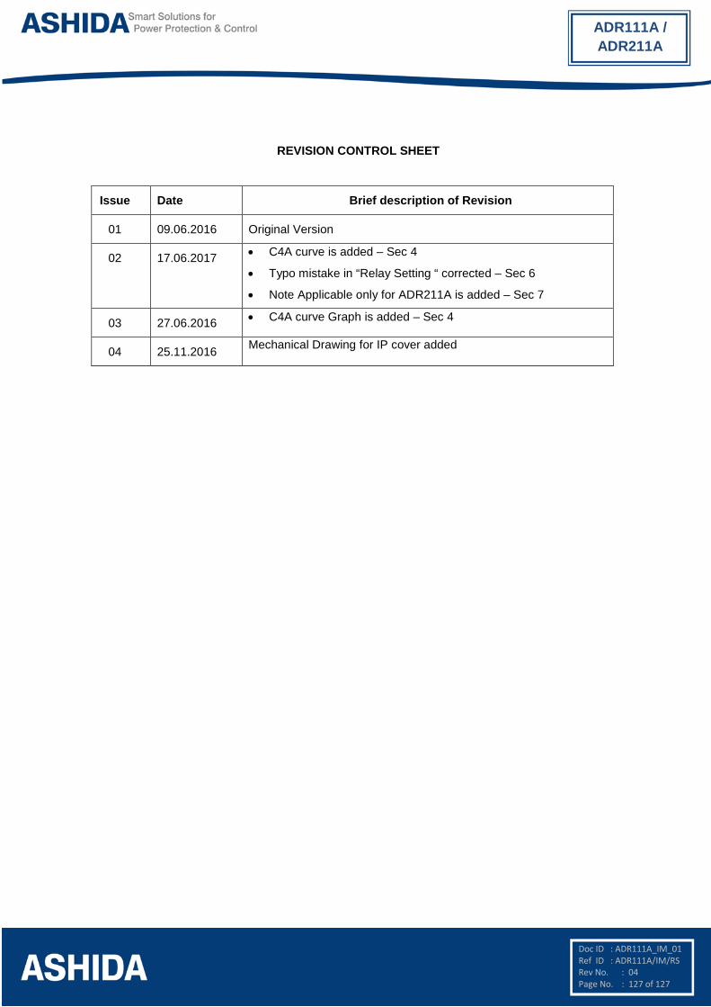
Doc ID : ADR111A_IM_01 Ref ID : ADR111A/IM/RS Rev No. : 04 Page No. : 127 of 127
ADR111A / ADR211A
REVISION CONTROL SHEET
Issue Date Brief description of Revision
01 09.06.2016 Original Version
02 17.06.2017 • C4A curve is added – Sec 4
• Typo mistake in “Relay Setting “ corrected – Sec 6
• Note Applicable only for ADR211A is added – Sec 7
03 27.06.2016 • C4A curve Graph is added – Sec 4
04 25.11.2016 Mechanical Drawing for IP cover added