Embed Size (px)
Citation preview

Installation Instruction
Single Pole Insulated Conductor Rail
0813 Series
MV0813-0008a-US www.conductix.us translated document page 1 of 15
Part number
0813xx-...
Contents
1 Product Description .................................................................................................................................................... 2
2 Check of the supplied Parts ....................................................................................................................................... 2
3 Notes ............................................................................................................................................................................ 2
4 Intended Use ................................................................................................................................................................ 2
5 Current Collector ......................................................................................................................................................... 3
6 Installation Sequence .................................................................................................................................................. 3
7 Pickup Guide ................................................................................................................................................................ 7
8 Maintenance ............................................................................................................................................................... 11
8.1 Hanger Clamps 081341-… and 081343-… ................................................................................................... 11
8.2 Rail Connectors 081321-… and Power Feeds 081351-… ............................................................................ 11
8.3 Expansion units 081362-… ........................................................................................................................... 11
8.4 Anchor Clamps 081331-… ............................................................................................................................ 11
8.5 Conductor Rails 0813XX-… .......................................................................................................................... 11
8.6 Current Collectors 081301-… to 081304-… .................................................................................................. 12
8.7 Heating Cable ................................................................................................................................................ 12
9 Relevant Components ............................................................................................................................................... 13

Installation Instruction
Single Pole Insulated Conductor Rail
0813 Series
MV0813-0008a-US www.conductix.us translated document page 2 of 15
1 Product Description
The single-pole insulated conductor rail product range 0813 is characterized by its ease of installation.
The conductor rail is released for horizontal installations in non-public areas. Local restrictions on use regarding protection
classes IP 21 and IP 00 around the current collector must be observed and structural measures taken and included in the
risk assessment for the CE conformity of the whole system.
2 Check of the supplied Parts
The components (see chapter 9) must be checked against the delivery note for completeness and transport damage. The
material is individually packed and marked for each system.
System Layout:
3 Notes
The conductor rail is installed on the existing support structure. This structure must be installed and checked for dimensional
accuracy before starting the installation. A maximum deviation of 5 mm relative to the track of the crane beam is permissible
in the horizontal and vertical. The squareness of the support structure relative to the crane-beam track must be ensured.
The various systems are implemented in accordance with the layout drawings, connection diagrams and part lists.
4 Intended Use
Power supply of mobile consumers in the non-public area. Protection class IP21 (current collector entry from the side) and
IP23 (current collector from below) for indoor and outdoor use outside the hand area.
End Cap
Conductor Rail Rail Connector
Towing Arm Current Collector
Line Feed
Support Arm
Hanger Clamp
PE (Green Stripe)
Anchor Clamp

Installation Instruction
Single Pole Insulated Conductor Rail
0813 Series
MV0813-0008a-US www.conductix.us translated document page 3 of 15
5 Current Collector
Always include redundancy for the PE current collector (at least one dual current collector). When using inverters, there must
also be redundancy for the phase-current collectors (protection against shutdown due to the loss of phase voltage in the case
of transient loss of contact).
6 Installation Sequence
Firstly, the hanger clamps are screwed to the existing brackets (support arms; tightening torque Mt = 14 Nm). The retaining
clamps must be able to pivot - realignment is not necessary. After attaching the hanger clamps, the conductor rails and
expansion units can be clipped into the clamps. Mean separation of hanger clamps and rail connectors: 400 mm!
Feed the conductor rail into the hanger clamp at around 45° Rail clipped into the hanger clamp
When cutting the conductor rail, the insulation profile and rail have to be cut separately. The cut direction is only top down
(avoid stainless steel strip to be disconnected from rail!). Use fine saw or angle grinder with fine cutting plate (no rough saw).
File a chamfer 1-2 mm 45° at the stainless steel strip at the end of the aluminum rail after cutting. This is important to avoid
sliding contact wear! Remove burrs from all other sharp edges of the rail by using a file!
CAUTION!
Copper and steel rails must also be prepared at the ends after cutting! A chamfer 1-
2 mm 45° is also required at the sliding surface for the current collector!
Sharp edges must be burred!
Support arm

Installation Instruction
Single Pole Insulated Conductor Rail
0813 Series
MV0813-0008a-US www.conductix.us translated document page 4 of 15
Pos. Designation
1 Stainless steel strip
2 Aluminum rail body
A = Chamfer at stainless steel strip
Insulation is 2x92.5 mm shorter than the conductor rail!
The rail sections are screwed together using rail connectors to form a single unit. In order to achieve a good ohmic contact,
the connection points (contact surfaces) are of bare metal thinly coated with conductive paste (080021). Half of an insulating
cap is pushed onto each prepared rail end. The conductor rails are now pushed into the connector from either end up to the
end stop (Al/steel rails) or to the inspection port. The nuts on the connector centrally located between the two rails to be
connected are tightened to a maximum tightening torque of Mt = 31 Nm. The insulating caps can now be pushed together
and connected using the two screws. This makes the connection point contact safe.

Installation Instruction
Single Pole Insulated Conductor Rail
0813 Series
MV0813-0008a-US www.conductix.us translated document page 5 of 15
Conductor rails with screwed connector Fully assembled rail connector
WARNING!
Destruction of the conductor rail!
Do not push the conductor rails together with force
Do not drive them with a hammer
Respect the tightening torque and use a torque wrench
Use conductive paste 080021
When trimming the conductor-rail sections, make always sure that the insulating profile is 185 mm shorter than the rail.
Anchor clamps: The hanger clamps are sliding supports. Therefore, to ensure uniform expansion on both sides, anchor
clamps have to be fixed, preferably at the center of the system or as per the attached layout drawing. The anchor clamps are
pushed onto the rails before the connectors are assembled and positioned the right and left of a hanger clamp.
Make sure the screws are accessible! The screws for securing the anchor clamp are only tightened
once the setting of the expansion units is complete.
Comment: No rail joints are necessary for systems with L
200 m. For systems with L > 200 m, see separate item in these
installation instructions.
Fixing point: anchor clamps arranged to the right and left of
the hanger clamp
Power feeds are to be installed in place of rail connectors as close as possible to the feed cable of the fixed installation. If
the power feed is to be attached within a rail section, the insulating profile needs to be cut at that point and trimmed by
92.5 mm on either side. In this case, it must be ensured that there is a clearance of 400 mm between the power feed and the
hanger clamp due to the temperature shift of the conductor rails. To ensure a permanently good ohmic contact, the clamping
points must be cleaned and thinly coated with conductive paste.
Hanger clamp
Always push the rails in as far as the end stop and with the mark-
ing point installed at the joint gap (gap of 2 mm between rail ends
is urgent necessary)
M 10

Installation Instruction
Single Pole Insulated Conductor Rail
0813 Series
MV0813-0008a-US www.conductix.us translated document page 6 of 15
As for the rail connectors, the halves of the insulating caps are pushed onto the rail ends. The two rail sections are then
pushed into the power supply clamp as far as the end stop and connected to it. The supply cable is inserted into the insulating
cap and attached to the power supply clamp (see the maximum tightening torque, Mt, for rail connectors). The two halves of
the insulating caps can now be pushed together and firmly connected using the two anchor screws. Before the final positioning
of the insulating caps, it is easy to check that the joint gap is exactly in the middle of the infeed and not too large (max. 3 mm)
using the inspection port in the power-supply clamp.
Power Feed: Fully assembled connections Power feed fitted with feed caps.
WARNING!
Destruction of the conductor rail!
Do not push the conductor rails together with force
Do not drive them with a hammer
Respect the tightening torque and use a torque wrench
Use conductive paste 080021
The expansion unit is supplied complete as a 5-m piece. Except of the installation of connectors right and left on the rail
ends, no further assembly is necessary. However, it must be ensured that the two air gaps of the rails in the rail joints — see
diagram on page 9 — are adjusted according to the ambient temperature on installation. The air gaps need to be checked
again when the anchor clamps have been installed.
As can be seen from the photo below, a hanger clamp (with securing arm) must be attached to the centerpiece of the expan-
sion unit.
Dual current collectors must be used when
using expansion units.
A hanger clamp must be fixed to the center-
piece of the expansion unit.
After completion of the rail assembly as far as the following anchor point, the two air gaps of the expansion unit can be set.
The size of the air gap can be taken from the diagram for the ambient temperature at the time of the installation.
Gap 2 mm/Rail Joint
The central axis of the cable must
be flush with the cable grommet
Hanger clamp
Expansion unit
Installation Instruction
Single Pole Insulated Conductor Rail
0813 Series
MV0813-0008a-US www.conductix.us translated document page 7 of 15
7 Pickup Guide
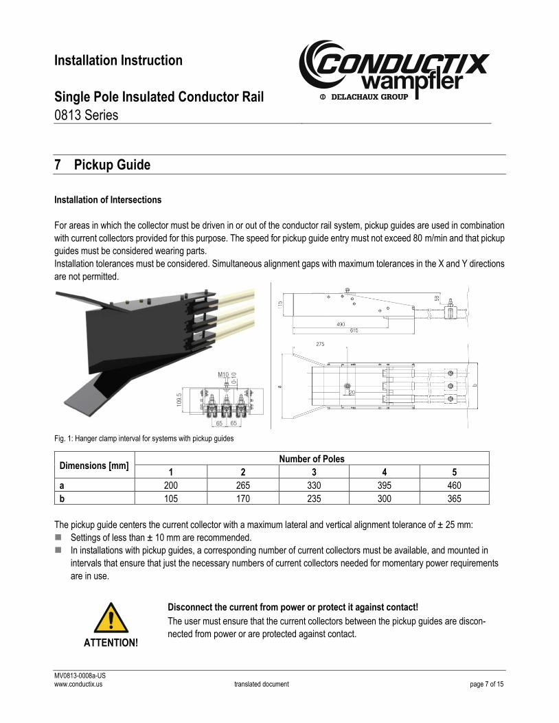
Installation of Intersections
For areas in which the collector must be driven in or out of the conductor rail system, pickup guides are used in combination
with current collectors provided for this purpose. The speed for pickup guide entry must not exceed 80 m/min and that pickup
guides must be considered wearing parts.
Installation tolerances must be considered. Simultaneous alignment gaps with maximum tolerances in the X and Y directions
are not permitted.
Fig. 1: Hanger clamp interval for systems with pickup guides
Dimensions [mm] Number of Poles
1 2 3 4 5
a 200 265 330 395 460
b 105 170 235 300 365
The pickup guide centers the current collector with a maximum lateral and vertical alignment tolerance of ± 25 mm:
Settings of less than ± 10 mm are recommended.
In installations with pickup guides, a corresponding number of current collectors must be available, and mounted in
intervals that ensure that just the necessary numbers of current collectors needed for momentary power requirements
are in use.
ATTENTION!
Disconnect the current from power or protect it against contact!
The user must ensure that the current collectors between the pickup guides are discon-
nected from power or are protected against contact.
Installation Instruction
Single Pole Insulated Conductor Rail
0813 Series
MV0813-0008a-US www.conductix.us translated document page 8 of 15
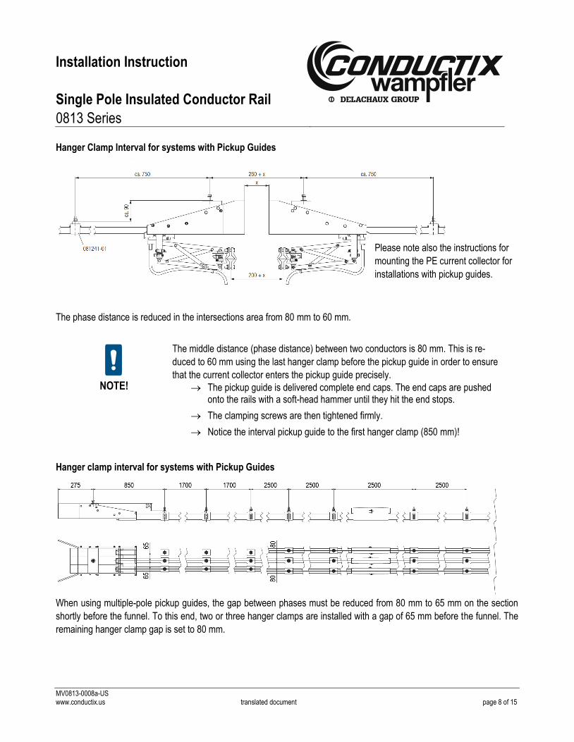
Hanger Clamp Interval for systems with Pickup Guides
The phase distance is reduced in the intersections area from 80 mm to 60 mm.
NOTE!
The middle distance (phase distance) between two conductors is 80 mm. This is re-
duced to 60 mm using the last hanger clamp before the pickup guide in order to ensure
that the current collector enters the pickup guide precisely.
The pickup guide is delivered complete end caps. The end caps are pushed onto the rails with a soft-head hammer until they hit the end stops.
The clamping screws are then tightened firmly.
Notice the interval pickup guide to the first hanger clamp (850 mm)!
Hanger clamp interval for systems with Pickup Guides
When using multiple-pole pickup guides, the gap between phases must be reduced from 80 mm to 65 mm on the section
shortly before the funnel. To this end, two or three hanger clamps are installed with a gap of 65 mm before the funnel. The
remaining hanger clamp gap is set to 80 mm.
Please note also the instructions for
mounting the PE current collector for
installations with pickup guides.

Installation Instruction
Single Pole Insulated Conductor Rail
0813 Series
MV0813-0008a-US www.conductix.us translated document page 9 of 15
NOTE!
Observe the reduced gap between phases near the funnel area
Use dual current collectors with vertical-motion limiters for the funnel paths
Remove PE deflectors for funnel applications
Disconnect the current collector near the transition or take construction measures for shock protection, such as the installation height, covers, etc.
Air gap installation with expansion units
Both rail joints must have the same air gap.
Instructions
tmin = lowest occurring temperature in the respective application
case
tmax = highest possible operating temperature in the respective
application case
1. Enter a tie line from tmin to tmax.
2. Enter a horizontal line at the ambient temperature dur-
ing installation.
3. Drop a line down from the intersection of the two lines,
and read off the air gap to adjust.
Examples:
= Temperature range from –15°C to +85°C
(ambient temperature during installation +30°C)
air gap (read off): 25 mm
= Temperature range from 0°C to +60°C
(ambient temperature during installation +10°C)
air gap (read off): 37 mm

Installation Instruction
Single Pole Insulated Conductor Rail
0813 Series
MV0813-0008a-US www.conductix.us translated document page 10 of 15
For conductor rail systems > 200 m, expansion units must be installed at certain intervals:
After setting the expansion unit, the anchor clamps are slid onto the hanger clamps and the clamping screws tightened. The
expansion unit, especially the air gaps, are checked again for the correct setting and clean continuity of the brushes.
The rail ends are protected by end caps that are pushed onto
the rail with light hammer taps (the outer edges of the rail ends
need to be deburred). The end caps are secured using clamp-
ing screws (firmly tightened).
The maximum distance from the cap end to the center of the
hanger clamp is 250 mm.
The use of the installation comb is indicated for setting the
hanger clamp interval when installing with support arms.
The standard center-to-center distance of the conductor rails is
80 mm.
At the end of the installation, the system must undergo electrical and mechanical testing over its entire length before the
system is put into operation.
The range of motion of the current collector over the entire traversing range must be checked in slow-speed mode.
50-mm interval
80-mm interval
2 × 40 mm
End cap Hanger clamp Support arm

Installation Instruction
Single Pole Insulated Conductor Rail
0813 Series
MV0813-0008a-US www.conductix.us translated document page 11 of 15
8 Maintenance
The following tests must be conducted at half-yearly intervals after commissioning the system.
8.1 Hanger Clamps 081341-… and 081343-…
a) Check for firm seating of screws and nuts.
b) Check that the conductor rail sits well in the hanger clamp.
c) The plastic clamp of the hanger clamp must be able to move within the tolerance limits on the conductor rail and must
not be jammed, so that the conductor rail can move through the sliding seating of the hanger clamp when the temper-
ature changes.
8.2 Rail Connectors 081321-… and Power Feeds 081351-…
a) Through the access slot in the conductor rail, check that the rails installed at these points do not have gaps greater
than a maximum of 3 mm and if necessary open up the rail connector and power feed and readjust.
b) Check whether the two adjacent rail ends have burrs and whether the contact heights are equal and remove burrs or
realign if necessary.
c) Check that the power supply clamping bolts are firmly seated.
8.3 Expansion units 081362-…
For expansion units, check the distance between the two neighboring rail ends at the ambient temperature prevailing during
the test in accordance with the installation instructions for conductor rail systems. If it can be seen from the graph that the
gap is not correct, it is essential to readjust it. Differences between the measured value and graph value 5 mm are to be
disregarded.
8.4 Anchor Clamps 081331-…
Check the anchor clamps for correct seating on the conductor rail and that they are attached as closely as possible left and
right of the hanger clamp. Readjust and tighten if necessary. The position of the anchor clamp must be compatible with the
functioning of the expansion unit.
8.5 Conductor Rails 0813XX-…
a) The insulation is to be visually inspected for cracks or deformation due to parts falling on the system or inadmissibly
excessive temperatures, replacing the insulating sleeve if necessary.
b) The wear resistance of the guide lips of insulating sleeve is also to be checked at the access slot. There is normally
no wear here. There may, however, be localized wear due to improper forced operation of the current collectors;
replace any worn insulating sleeves and check the current-collector system at these points and readjust as specified
in the drawing if necessary.

Installation Instruction
Single Pole Insulated Conductor Rail
0813 Series
MV0813-0008a-US www.conductix.us translated document page 12 of 15
8.6 Current Collectors 081301-… to 081304-…
a) Check the installation dimensions in accordance with catalog KAT0813-0001 and adjust if necessary.
b) Check the contact force of the carbon brushes with a spring balance. The contact force must be 28 N. If this is not
the case, the springs must be replaced.
c) Check the position and securing of the connecting cables. These connecting cables must not affect the current
collector heads. The proper positioning and functioning of the current collector heads can be determined very eas-
ily:
The outer current-collector heads are withdrawn from the conductor rail and held against the rail. The brushes
must be at the height of the contact surface and parallel to it. If this is not the case, the fastening of the connecting
cable must be corrected. The cables must be adjusted accordingly in all further current collector heads.
d) The carbon brushes must be replaced if they are worn down to approximately 2 mm from the insulation of the
brushing.
e) Lightly oil the joints and bolts.
Always include redundancy for the PE current collector (at least one dual current collector). When using inverters, there
must also be redundancy for the phase current collectors (protection against shutdown due to the loss of phase voltage in
the case of transient loss of contact).
8.7 Heating Cable
a) Check all circuit breakers and replace it if necessary.
b) Check all heating cable runs for continuity.
CAUTION!
Only use solvent-free cleaning agents!
When cleaning rails and power consumers, it must be ensured that only solvent-free
cleaning agents are used that do not have an aggressive action on or destroy plastics
such as PVC, PC and PBTP (see WV0800-0001).
You can find further information in the catalog KAT0813-0001!
Installation Instruction
Single Pole Insulated Conductor Rail
0813 Series
MV0813-0008a-US www.conductix.us translated document page 13 of 15
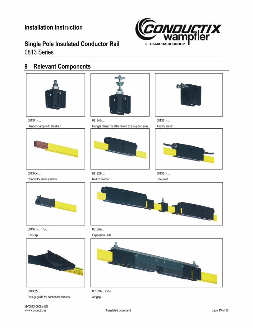
9 Relevant Components
081341-...;
Hanger clamp with steel nut
081343-...;
Hanger clamp for attachment to a support arm
081331-...;
Anchor clamp
0813XX-...
Conductor rail/insulation
081321-...;
Rail connector
081351-...;
Line feed
081371-... / 73-...
End cap
081362-...
Expansion units
081382-...
Pickup guide for section transitions
081394-... / 95-...
Air gap

Installation Instruction
Single Pole Insulated Conductor Rail
0813 Series
MV0813-0008a-US www.conductix.us translated document page 14 of 15
020186-...;
Support arm
020286-...;
Bracket for support arm
020180-...;
Clamping bracket
020197-...;
Towing arm
080052-...;
Cable lug for supply cable
080401-... / 02- / 03-...;
Insulator
081301-...;
Current collector
081301-...;
Dual current collector (standard)
081003-...;
Carbon brush (spare part)
081302-... / 03-... / 04-...
Dual current collector for section transitions

Installation Instruction
Single Pole Insulated Conductor Rail
0813 Series
MV0813-0008a-US www.conductix.us translated document page 15 of 15
USA / Latin America
10102 F Street
Omaha, NE 68 127
Customer Support
Phone +1-800-521-4888
Phone +1-402-339-9300
Fax +1-402-339-9627
Canada
1435 Norjohn Court
Unit 5
Burlington, ON L7L 0E6
Customer Support
Phone +1-800-667-2487
Phone +1-450-565-9900
Fax +1-450-851-8591
México
Calle Treviño 983-C
Zona Centro
Apodaca, NL México 66600
Customer Support
Phone (+52 81) 1090 9519
(+52 81) 1090 9025
(+52 81) 1090 9013
Fax (+52 81) 1090 9014
Brazil
Rua Luiz Pionti, 110
Vila Progresso
Itu, São Paulo, Brasil
CEP: 13313-534
Customer Support
Phone (+55 11) 4813 7330
Fax (+55 11) 4813 7357
To contact our global sales offices, please refer to:
www.conductix.com/contact-search