Embed Size (px)
Citation preview
Ch
apte
r: A
dm
inis
trat
ion
Use
r G
uid
e
2
ADMINISTRATION USER GUIDE
SoftBox Limited Atrium House
574 Manchester Road
BURY
BL9 9SW
www.softboxlimited.co.uk
0161 766 1777

Ch
apte
r: A
dm
inis
trat
ion
Use
r G
uid
e
3
Ch
apte
r: C
on
ten
ts
4
CONTENTS
Administration User Guide ....................................................................................................................... 2
Contents ................................................................................................................................................... 4
Hardware Requirements .......................................................................................................................... 6
Installation ................................................................................................................................................ 8
Getting Started ....................................................................................................................................... 14
Form Controls ......................................................................................................................................... 16
Creating Menus ...................................................................................................................................... 18
System Options ....................................................................................................................................... 20
Maintaining Lists ..................................................................................................................................... 24
Team Details ........................................................................................................................................... 26
Staffing Details ........................................................................................................................................ 28
User ID Details ........................................................................................................................................ 32
Reset Users Logged On ........................................................................................................................... 36
Data Groups ............................................................................................................................................ 38
Quick Query ............................................................................................................................................ 42
Application Help ..................................................................................................................................... 44
Finance ................................................................................................................................................... 46
Budget Maintenance .............................................................................................................................. 48
Ch
apte
r: C
on
ten
ts
5
Account Codes ........................................................................................................................................ 50
Transaction Files ..................................................................................................................................... 52
Releasing Transaction Files ..................................................................................................................... 54
Deleting Records..................................................................................................................................... 56
Field Level Properties ............................................................................................................................. 58
Record Masking ...................................................................................................................................... 60
Administration Module Functional Specification ................................................................................... 62
Hardware Requirements ................................................................................................................... 63
Application Environment .................................................................................................................... 65
Application Security ............................................................................................................................ 67
Common Functions ............................................................................................................................. 70
System Configuration ......................................................................................................................... 72
Finance ............................................................................................................................................... 75
Reporting Tools................................................................................................................................... 76
Ch
apte
r: H
ard
war
e R
equ
ire
men
ts
6
HARDWARE REQUIREMENTS
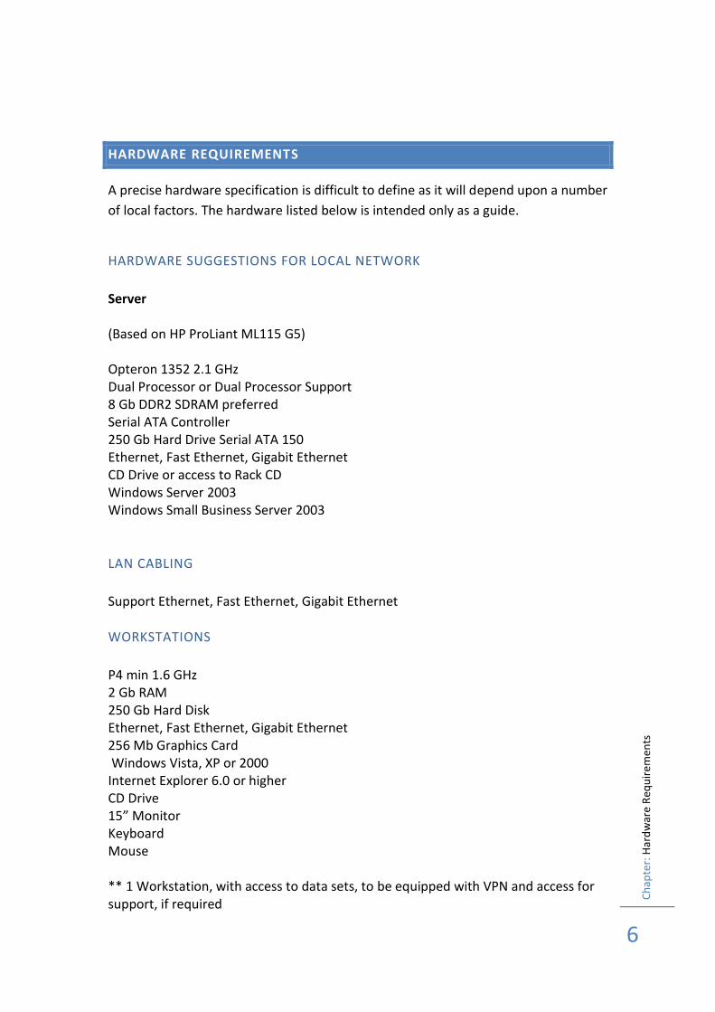
A precise hardware specification is difficult to define as it will depend upon a number
of local factors. The hardware listed below is intended only as a guide.
HARDWARE SUGGESTIONS FOR LOCAL NETWORK
Server (Based on HP ProLiant ML115 G5) Opteron 1352 2.1 GHz Dual Processor or Dual Processor Support 8 Gb DDR2 SDRAM preferred Serial ATA Controller 250 Gb Hard Drive Serial ATA 150 Ethernet, Fast Ethernet, Gigabit Ethernet CD Drive or access to Rack CD Windows Server 2003 Windows Small Business Server 2003
LAN CABLING
Support Ethernet, Fast Ethernet, Gigabit Ethernet
WORKSTATIONS
P4 min 1.6 GHz 2 Gb RAM 250 Gb Hard Disk Ethernet, Fast Ethernet, Gigabit Ethernet 256 Mb Graphics Card Windows Vista, XP or 2000 Internet Explorer 6.0 or higher CD Drive 15” Monitor Keyboard Mouse ** 1 Workstation, with access to data sets, to be equipped with VPN and access for support, if required

Ch
apte
r: H
ard
war
e R
equ
ire
men
ts
7
Ch
apte
r: In
stal
lati
on
8
INSTALLATION
Installation must take place on a machine that has been previously installed with Windows 2000 or XP Professional. Workstations also require Internet Explorer 6.0 or higher. Before you begin the installation process check the hard disk and decide where you want to install the application. The default directory used during installation is C:\SBAPPS\nnn\ and its sub-directories \DATAFILE and \STATFILE. Software will be installed automatically to the workstation. Databases and other folders are located in \COMMON\ on the CD. These should be copied to either the server or workstation in the case of a standalone installation, before running the application. If the application is to be networked, it is recommended that the data files are copied to the server first and that the users are given read, write and create privileges on all the folders and their contents. The users should also be given access to this area using a designated mapped drive. Please note that this application does not recognise long folder names or spaces in the path name. We recommend that the path name is kept short e.g. ‘SBAPPS’
STARTING THE WORKSTATION INSTALLATION PROCESS - WINDOWS 2000 OR
XP
During the installation process you can use the mouse to make selections. If you use the keyboard you can press Tab to select options or buttons. After selecting a check box or button with the Tab key, press the Enter key to complete the selection. Pressing Enter is the same as OK. Pressing Esc is the same as Cancel. To begin installing follow these steps: First close any open programs by displaying the taskbar, if hidden, and right click on the program button, and click Close on the menu that appears If you are installing for the first time from CD-ROM, set-up starts automatically. You can skip the following steps, unless the CD-ROM installation does not start automatically. Click the Start button on the taskbar, then click Run When the Run dialogue box appears, type d:\setup, where D is the CD drive. If you have not already closed any open applications, you may get a message to close them before continuing. Click the Install button and follow the instructions. A set-up box will show the path to which the application will be installed. The default path is C:\SBAPPS\nnn\ Copy the files located in \COMMON\ to either the PC directory or a location on the server. NOTE: files copied from a CD will be read only unless the file attributes are
Ch
apte
r: In
stal
lati
on
9
changed (does not apply to Windows XP). It is essential that these file attributes are changed before attempting to run the application. Once all the files have been installed on your machine, if you need to change the default settings it will be necessary to run the SBSETUP utility, which is described below.
DIRECTORY STRUCTURES
The workstation directory structure is as follows: C:\SBAPPS\nnn This is the main application directory and contains the EXE file and configuration files. These are also the files that should be located upon individual workstations, if the application is being run in a network environment. This installation method is recommended in order to gain maximum performance benefits. A subfolder ‘nnn’ may also be included when products are being used singly C:\SBAPPS\nnn\BACKUP This folder is used for storing backups generated by the internal backup procedure. If this directory is not installed, it will be created automatically by the application. C:\SBAPPS\nnn\ICONS This folder holds the icons used by the application. C:\SBAPPS\nnn\MANUAL This folder stores a copy of this manual, and any additional User Guides that are required to support the individual options that have been purchased. The documents are in Word 2000 document format as a self-extracting EXE file C:\SBAPPS\nnn\PRIVATE This folder contains sub folders. These folders are created the first time the application is run at the location specified during installation see PC or Server Data Installation ..\PRIVATE\QUERIES This contains any letters etc. that have been set up as ‘private’ utilities in the application.
The workstation installation should be repeated at each PC that will require access to the application.
Ch
apte
r: In
stal
lati
on
10
PC OR SERVER DATA INSTALLATION
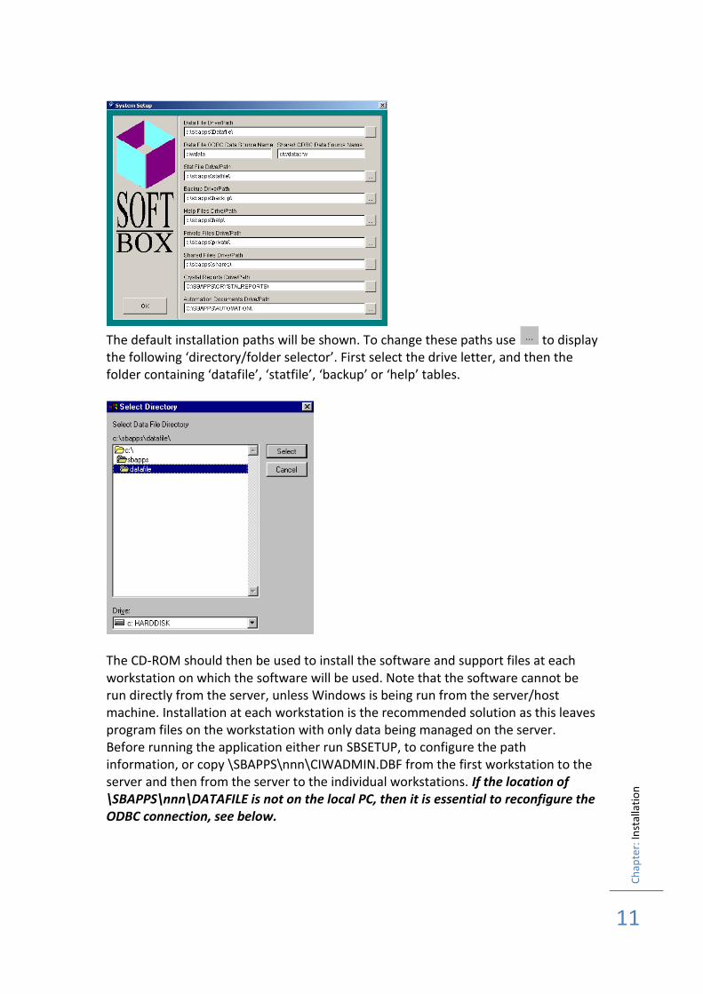
Before running the application, copy the following folders which are located on the CD in \COMMON\ to either a server location or to C:\SBAPPS\nnn\ if the application is being run as a stand-alone. C:\SBAPPS\nnn\AUTOMATION This folder holds master templates of reports, spreadsheets etc. which are used by the application to create reports C:\SBAPPS\nnn\CRYSTALREPORTS This folder is used to store Crystal Reports, which have been included in the application C:\SBAPPS\nnn\DATAFILE This folder contains all databases storing client and provider details. C:\SBAPPS\nnn\HELP This directory stores all associated help files for F1 help. These are in HTML format and require Internet Explorer C:\SBAPPS\nnn\SHARED This folder contains sub folders. The root folder is also used to store files created by users for use with Crystal Reports ..\SHARED\QUERIES This contains any letters etc. that have been set up as ‘shared’ utilities in the application. ..\SHARED\SAVEDOCS this folder retains a history of user defined documents, reports etc. It is also used by the application to store copies of DfES Returns and similar key documents ..\SHARED\UPDATES This folder contains new program files, which will have been loaded by a System Refresh procedure. This file will be copied automatically to any workstation the first time of logging on after a refresh. C:\SBAPPS\nnn\STATFILE This directory is used to store the list files for use by fields such as ‘District’ Once this task has been completed the utility SBSETUP should be run from C:\SBAPPS\nnn\ to identify the paths that are being used for the folders copied from the \COMMON\ folder on the CD. Before running SBSETUP ensure that the necessary privileges and drive designation has been completed. SBSETUP is run from the application directory, and the form is shown below:
Ch
apte
r: In
stal
lati
on
11
The default installation paths will be shown. To change these paths use to display the following ‘directory/folder selector’. First select the drive letter, and then the folder containing ‘datafile’, ‘statfile’, ‘backup’ or ‘help’ tables.
The CD-ROM should then be used to install the software and support files at each workstation on which the software will be used. Note that the software cannot be run directly from the server, unless Windows is being run from the server/host machine. Installation at each workstation is the recommended solution as this leaves program files on the workstation with only data being managed on the server. Before running the application either run SBSETUP, to configure the path information, or copy \SBAPPS\nnn\CIWADMIN.DBF from the first workstation to the server and then from the server to the individual workstations. If the location of \SBAPPS\nnn\DATAFILE is not on the local PC, then it is essential to reconfigure the ODBC connection, see below.
Ch
apte
r: In
stal
lati
on
12
CREATING A SHORTCUT
If a shortcut is required on the desktop, please note that the executable programme is named LOADER.EXE. This executable includes a facility to automatically update application executables if they have been changed since the last time the programme was used.
INSTALLING A SYSTEM REFRESH
From time to time SoftBox will despatch to you a ‘System Refresh’. This may be to apply some modifications requested by you, or as part of a general upgrade of the application. When a refresh disk set or CD-ROM is received, it is installed in the same way as the original software. A System Refresh is always installed from a workstation. When using a CD-ROM it will launch automatically. The Refresh disk will prompt for the location of the application \SBAPPS\nnn\. Folders ..\DATAFILE and ..\STATFILE will then be backed up into date named sub-directories, before new data structures are installed and data copied to them. A new program file is then installed to the workstation and to the UPDATES folder, for use by other users.
ODBC CONNECTIVITY
ODBC connections will be created automatically as part of the installation process. If you wish to run the ODBC administrator, it will be found in StartSettings Control Panel. To view the connections, select System DSN tab card, highlight the connection name and use Properties
The connection uses Microsoft Visual FoxPro Driver (Version 6.01.8629.01) PLEASE NOTE: The version number is important as earlier versions may not contain the require Options (see below). Data Source name nnnDATA Description SoftBox Application Data Database Type Visual FoxPro Database Path C:\SBAPPS\nnn\DATAFILE\CIW_DATA.DBC or network path as appropriate Options only deleted and fetch data in background required. Exclusive and null should not be selected. If they are shown ‘ticked’, this should be removed. A second connection for the shared options is required. Follow the same procedure for viewing the second connection. Data Source name nnnDATACRW Database Type Free Table Directory Path C:\SBAPPS\nnn\SHARED\ or network path as appropriate Options only deleted and fetch data in background required.

Ch
apte
r: In
stal
lati
on
13
Note that the ODBC connection name is a default setting. If required the connection name can be changed by using SBSETUP. The same connection name MUST be used for all installed PC’s, otherwise connectivity errors will occur.
Ch
apte
r: G
etti
ng
Star
ted
14
GETTING STARTED
To start the application use the left mouse button to click on Start select Programs, SoftBox Applications, Application Name, Log On. The User ID and Password form is then displayed. Before entering the User ID/Password details a brief description about how the information in this training guide is presented.
This is used to denote a click on the left mouse button or ‘‘ is used to signify a double click. A right mouse button click is signified by the symbol . E.g. Cancel means click once, using the left mouse button, on the Cancel button on screen.
Forms Client
When the mouse is used with a key word it signifies menu choices. For example,
Forms Client to indicate select Forms from the menu bar and Client from the menu popup that is displayed beneath it.
Tab
You will find it easier if the
‘Tab’ key is used to move between one data item and the next, rather than the Enter key. Tab is usually to the left of the letter ‘Q’ and above ‘Caps Lock’. Just take a moment to locate it, if you are not sure
Ch
apte
r: G
etti
ng
Star
ted
15
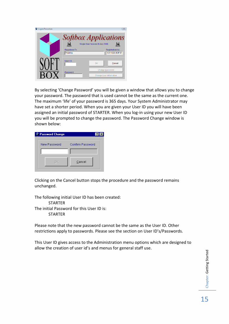
By selecting ‘Change Password’ you will be given a window that allows you to change your password. The password that is used cannot be the same as the current one. The maximum ‘life’ of your password is 365 days. Your System Administrator may have set a shorter period. When you are given your User ID you will have been assigned an initial password of STARTER. When you log-in using your new User ID you will be prompted to change the password. The Password Change window is shown below:
Clicking on the Cancel button stops the procedure and the password remains unchanged. The following initial User ID has been created: STARTER The initial Password for this User ID is: STARTER Please note that the new password cannot be the same as the User ID. Other restrictions apply to passwords. Please see the section on User ID’s/Passwords. This User ID gives access to the Administration menu options which are designed to allow the creation of user id’s and menus for general staff use.
Ch
apte
r: F
orm
Co
ntr
ols
16
FORM CONTROLS
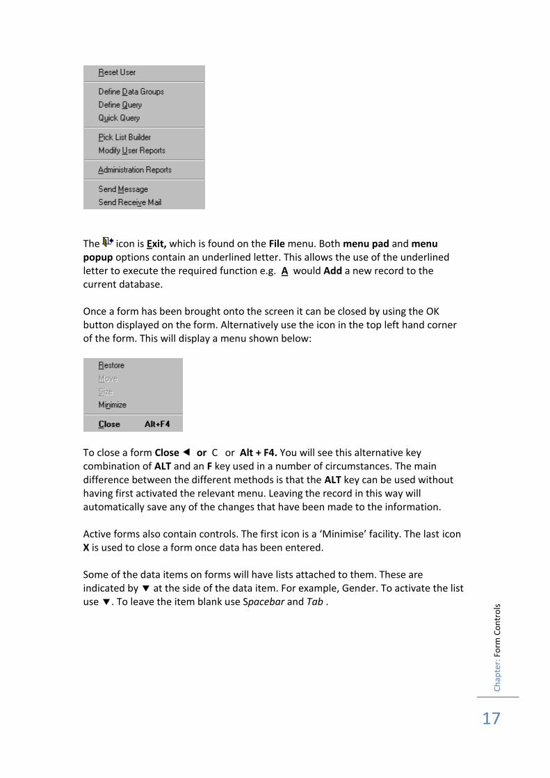
The application is organised around an ‘application desktop’ of which the standard menu controls, described in the previous section are part. The desktop however contains a number of additional controls, and the individual forms also contain controls for displaying additional forms. The icons displayed on the tool bars use the latest Windows ‘flat buttons’. This means that all options appear flat and not as raised buttons used in earlier applications. A disabled button is shown in pale grey. All options that have been enabled will be shown in black or subdued colour. When the mouse pointer passes over an enabled option the full colour icon is shown and the button is raised. To select the raised icon button use as with previous icon tool bars. The icons displayed on a toolbar are controlled as part of the set up of profiles discussed in the next section. To maintain a standard, it is recommended that icons controlling forms should be placed on the top toolbar, whilst those for actions, e.g. Add are placed on the left toolbar. Each tool bar icon also has a ‘tip’ attached to it. Pausing on the icon will reveal the ‘tip’. E.g. the first icon tip is Clients. The first three icons control the most commonly used forms - Clients, Carers and Resources. Attached to each of these icons is a button which when activated, displays a list of the last ten records used in this session. They are displayed in most recent first. The purpose of this is to allow the user to quickly re-select a record without the need for using trace facilities. The top toolbar should always include the exit icon, is Exit. Navigation within records is always managed by displaying a list of entries for the form, within a list box. This list box will contain details from the record, enabling its identification. Once a record has been selected using the form will be refreshed with the details of the selected record. The ‘cut and paste’ tools when available, are used to exchange details with the Windows clipboard. The first tool cuts the selected text, copies the highlighted text to the clipboard and finally to paste the contents of the clipboard into the notes area. Additionally, all forms can be controlled using the menu bar as described in the section ‘General Control Descriptions’. In the sample Administration menu shown below a number of options have been included, with the underscored letter shown.
Ch
apte
r: F
orm
Co
ntr
ols
17
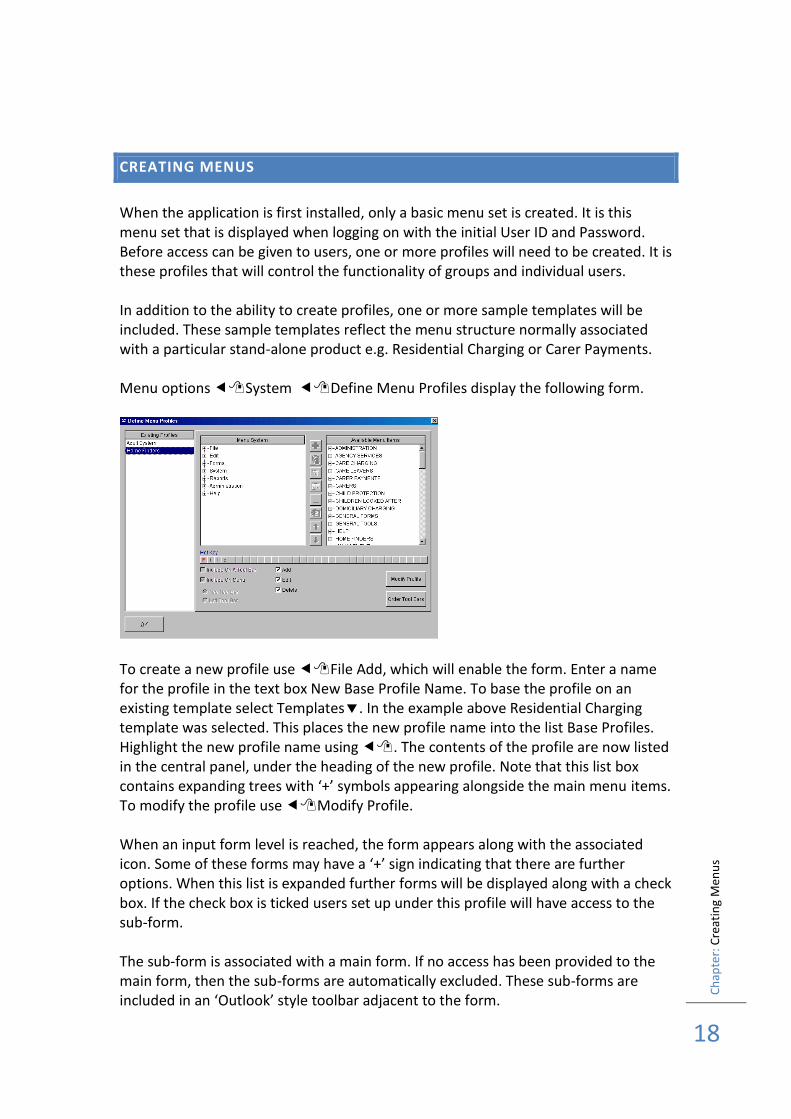
The icon is Exit, which is found on the File menu. Both menu pad and menu popup options contain an underlined letter. This allows the use of the underlined letter to execute the required function e.g. A would Add a new record to the current database. Once a form has been brought onto the screen it can be closed by using the OK button displayed on the form. Alternatively use the icon in the top left hand corner of the form. This will display a menu shown below:
To close a form Close or C or Alt + F4. You will see this alternative key combination of ALT and an F key used in a number of circumstances. The main difference between the different methods is that the ALT key can be used without having first activated the relevant menu. Leaving the record in this way will automatically save any of the changes that have been made to the information. Active forms also contain controls. The first icon is a ‘Minimise’ facility. The last icon X is used to close a form once data has been entered. Some of the data items on forms will have lists attached to them. These are indicated by at the side of the data item. For example, Gender. To activate the list use . To leave the item blank use Spacebar and Tab .
Ch
apte
r: C
reat
ing
Men
us
18
CREATING MENUS
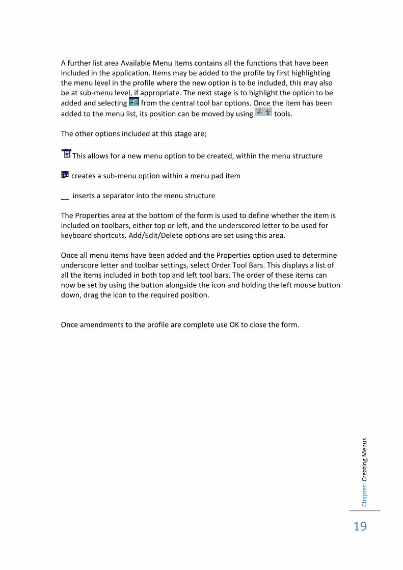
When the application is first installed, only a basic menu set is created. It is this menu set that is displayed when logging on with the initial User ID and Password. Before access can be given to users, one or more profiles will need to be created. It is these profiles that will control the functionality of groups and individual users. In addition to the ability to create profiles, one or more sample templates will be included. These sample templates reflect the menu structure normally associated with a particular stand-alone product e.g. Residential Charging or Carer Payments. Menu options System Define Menu Profiles display the following form.
To create a new profile use File Add, which will enable the form. Enter a name for the profile in the text box New Base Profile Name. To base the profile on an existing template select Templates. In the example above Residential Charging template was selected. This places the new profile name into the list Base Profiles. Highlight the new profile name using . The contents of the profile are now listed in the central panel, under the heading of the new profile. Note that this list box contains expanding trees with ‘+’ symbols appearing alongside the main menu items. To modify the profile use Modify Profile. When an input form level is reached, the form appears along with the associated icon. Some of these forms may have a ‘+’ sign indicating that there are further options. When this list is expanded further forms will be displayed along with a check box. If the check box is ticked users set up under this profile will have access to the sub-form. The sub-form is associated with a main form. If no access has been provided to the main form, then the sub-forms are automatically excluded. These sub-forms are included in an ‘Outlook’ style toolbar adjacent to the form.
Ch
apte
r: C
reat
ing
Men
us
19
A further list area Available Menu Items contains all the functions that have been included in the application. Items may be added to the profile by first highlighting the menu level in the profile where the new option is to be included, this may also be at sub-menu level, if appropriate. The next stage is to highlight the option to be
added and selecting from the central tool bar options. Once the item has been
added to the menu list, its position can be moved by using tools. The other options included at this stage are;
This allows for a new menu option to be created, within the menu structure
creates a sub-menu option within a menu pad item __ inserts a separator into the menu structure The Properties area at the bottom of the form is used to define whether the item is included on toolbars, either top or left, and the underscored letter to be used for keyboard shortcuts. Add/Edit/Delete options are set using this area. Once all menu items have been added and the Properties option used to determine underscore letter and toolbar settings, select Order Tool Bars. This displays a list of all the items included in both top and left tool bars. The order of these items can now be set by using the button alongside the icon and holding the left mouse button down, drag the icon to the required position. Once amendments to the profile are complete use OK to close the form.
Ch
apte
r: S
yste
m O
pti
on
s
20
SYSTEM OPTIONS
There are a number of system controls, which affect the way in which the application will behave when in use. These options are contained on the System Options Form, which in a standard menu layout is found by using System System Options
PAGE 1
Local Authority Address is used to record address and postcode details of the local authority. This is used to support some of the Statistical Returns to central bodies Phone No 1 to be included on a return Phone No 2 to be included on a return Fax to be included on a return Email to be included on a return Language defines the contents of some of the drop down lists that are used by the application e.g. legal status. The options are SCO,ENG,WAL,E&W,E&S Use Online Help sets the system to use help from www.softboxlimited.co.uk online rather than the help files that are held locally. This is to allow the users to get the most up to date information a form that they are using Automatic Client References determines whether a system generated reference number is used or the data item is left blank for a user-keyed number Automatic Provider References determines whether a system generated reference number is used or the data item is left blank for a user-keyed number Automatic Account Numbers creates both Client and Provider account numbers without the need to enter manually. The number is 6 digits followed by an alpha check character Automatic Ages Update ensures that client/provider chronological ages are maintained. Alternatively, it can be run from the menu options Record All Changes is used to maintain an audit trail of all data entry or change items, together with details of the user making the change Automatic Index Check is used to check any new client name that is entered against a list of names already held by the application. The check is a ‘sounds like’ check in order to maximise the options. If a match is found the record can be used to copy details from another client, for example, when entering sibling groups Use Referral/Worker Allocation indicates that the referral/allocation module is being used within the application. The implication of this selection is that when options for team or worker details are used on forms, only those teams and workers that have been created by the allocation process will be displayed. If this option is not used then standard pick-lists will be shown. These lists will be created from the
Ch
apte
r: S
yste
m O
pti
on
s
21
details entered into the Team Details and Staffing forms. For list purposes only minimum details will be required e.g. team name and worker name 256 Colour Mode changes the screen display to 256 colours, for installations where ‘true’ colours are not available. Small List Icons reduces the size of the icon in the ‘Outlook’ style toolbar so that more options can be displayed without the need to scroll Perform LAC Checks This option is sued in conjunction with the LAC module and ensures that entries are validated against LAC rules Provider Types allows the system to be configured for specific options that may be selected when adding a new provider Use Account Code Linking is an option that when enabled will allow budget codes to be defined by their unique relationship with each other, so that it is possible to specify that when a particular part 1 code is selected, only certain options are available in the part 2 choices. For more information in this see the section titled ‘Account Codes’
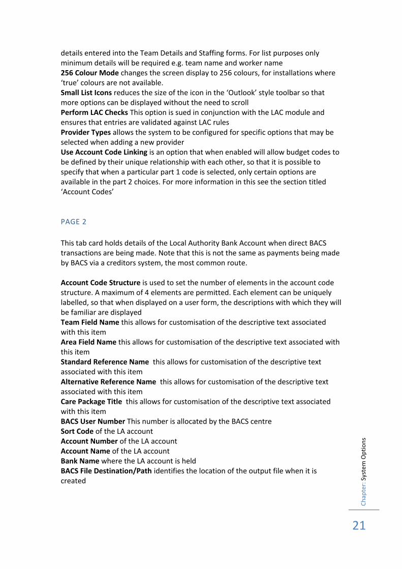
PAGE 2
This tab card holds details of the Local Authority Bank Account when direct BACS transactions are being made. Note that this is not the same as payments being made by BACS via a creditors system, the most common route. Account Code Structure is used to set the number of elements in the account code structure. A maximum of 4 elements are permitted. Each element can be uniquely labelled, so that when displayed on a user form, the descriptions with which they will be familiar are displayed Team Field Name this allows for customisation of the descriptive text associated with this item Area Field Name this allows for customisation of the descriptive text associated with this item Standard Reference Name this allows for customisation of the descriptive text associated with this item Alternative Reference Name this allows for customisation of the descriptive text associated with this item Care Package Title this allows for customisation of the descriptive text associated with this item BACS User Number This number is allocated by the BACS centre Sort Code of the LA account Account Number of the LA account Account Name of the LA account Bank Name where the LA account is held BACS File Destination/Path identifies the location of the output file when it is created

Ch
apte
r: S
yste
m O
pti
on
s
22
SECURITY
Encrypt Passwords This option encrypts user passwords so that they cannot be viewed, even when the table is opened externally. All passwords are converted to a 10 character entry. Show Passwords option is used to determine the display of User passwords when viewing the User ID form for an individual. This setting should be determined by reference to internal procedures Allow Field Level Properties This enables the feature described on page 56 in this manual Change Administrator ID This allows the for the User ID (default STARTER) to be changed when accessing the Systems Administration part of the system

Ch
apte
r: S
yste
m O
pti
on
s
23
Ch
apte
r: M
ain
tain
ing
List
s
24
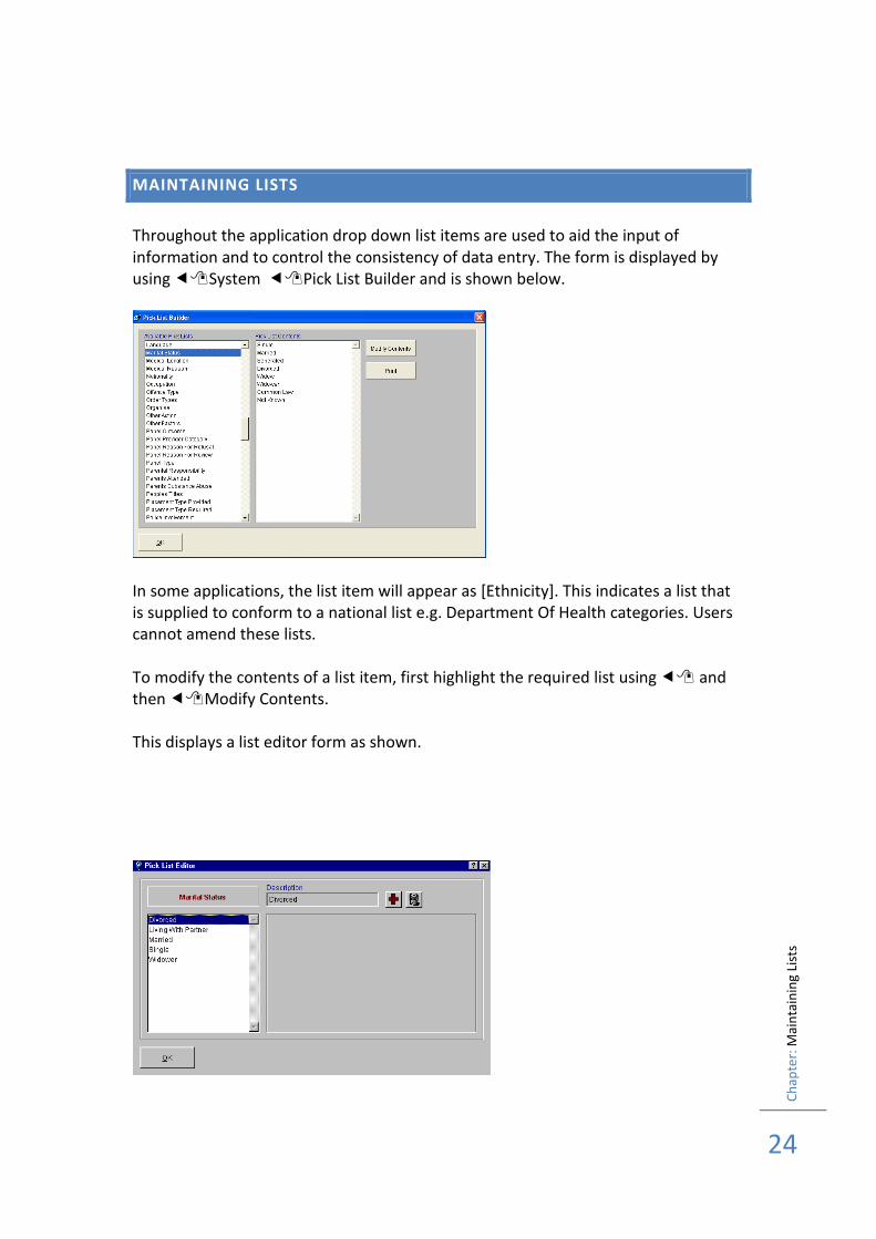
MAINTAINING LISTS
Throughout the application drop down list items are used to aid the input of information and to control the consistency of data entry. The form is displayed by using System Pick List Builder and is shown below.
In some applications, the list item will appear as [Ethnicity]. This indicates a list that is supplied to conform to a national list e.g. Department Of Health categories. Users cannot amend these lists. To modify the contents of a list item, first highlight the required list using and then Modify Contents. This displays a list editor form as shown.

Ch
apte
r: M
ain
tain
ing
List
s
25
Note that the list name is displayed on the form, and the current contents are displayed in the left hand list panel. To remove an existing entry highlight using and then use the delete icon. To add new list items, use the add icon and type the required entry into the description box. Note that proper case is always enforced. Once amendments to the list are complete use OK to close the form and return to the previous form. When an Account Code list item is selected for maintenance, an additional item is displayed, which allows for a description of the Budget Code to be entered. At a later stage when this option is used for data input, both the code and the description will be shown to the user, to aid selection of the correct code. Print This enables the list to be printed
Ch
apte
r: T
eam
Det
ails
26
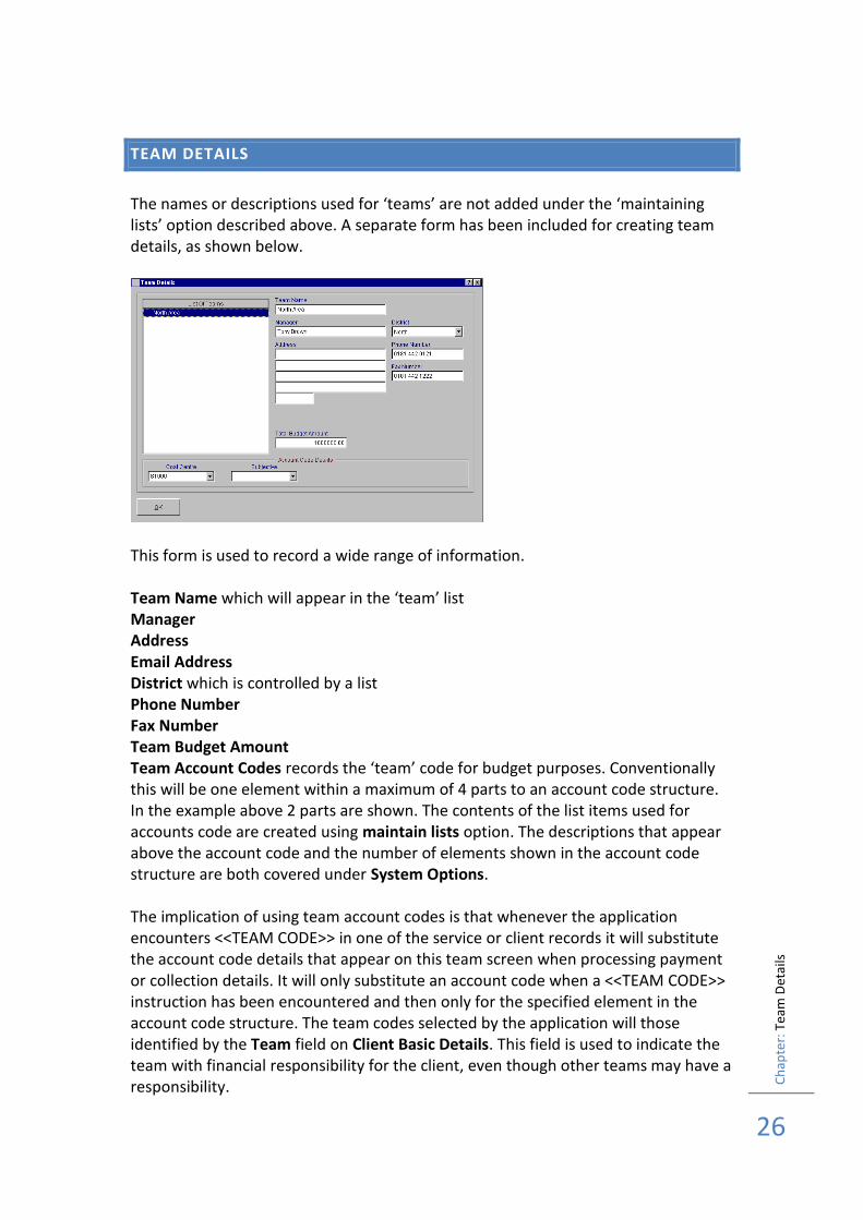
TEAM DETAILS
The names or descriptions used for ‘teams’ are not added under the ‘maintaining lists’ option described above. A separate form has been included for creating team details, as shown below.
This form is used to record a wide range of information. Team Name which will appear in the ‘team’ list Manager Address Email Address District which is controlled by a list Phone Number Fax Number Team Budget Amount Team Account Codes records the ‘team’ code for budget purposes. Conventionally this will be one element within a maximum of 4 parts to an account code structure. In the example above 2 parts are shown. The contents of the list items used for accounts code are created using maintain lists option. The descriptions that appear above the account code and the number of elements shown in the account code structure are both covered under System Options. The implication of using team account codes is that whenever the application encounters <<TEAM CODE>> in one of the service or client records it will substitute the account code details that appear on this team screen when processing payment or collection details. It will only substitute an account code when a <<TEAM CODE>> instruction has been encountered and then only for the specified element in the account code structure. The team codes selected by the application will those identified by the Team field on Client Basic Details. This field is used to indicate the team with financial responsibility for the client, even though other teams may have a responsibility.

Ch
apte
r: T
eam
Det
ails
27
Once a Team has been entered in Team Name this will be used by the Team list, when the application is not using Referral/Worker Allocation Details (see System Options). The team list cannot be maintained using the list editor feature. If referral options are used, then only team names that have been allocated, via a referral, to the client will be displayed as options in the drop down list.
Ch
apte
r: S
taff
ing
Det
ails
28
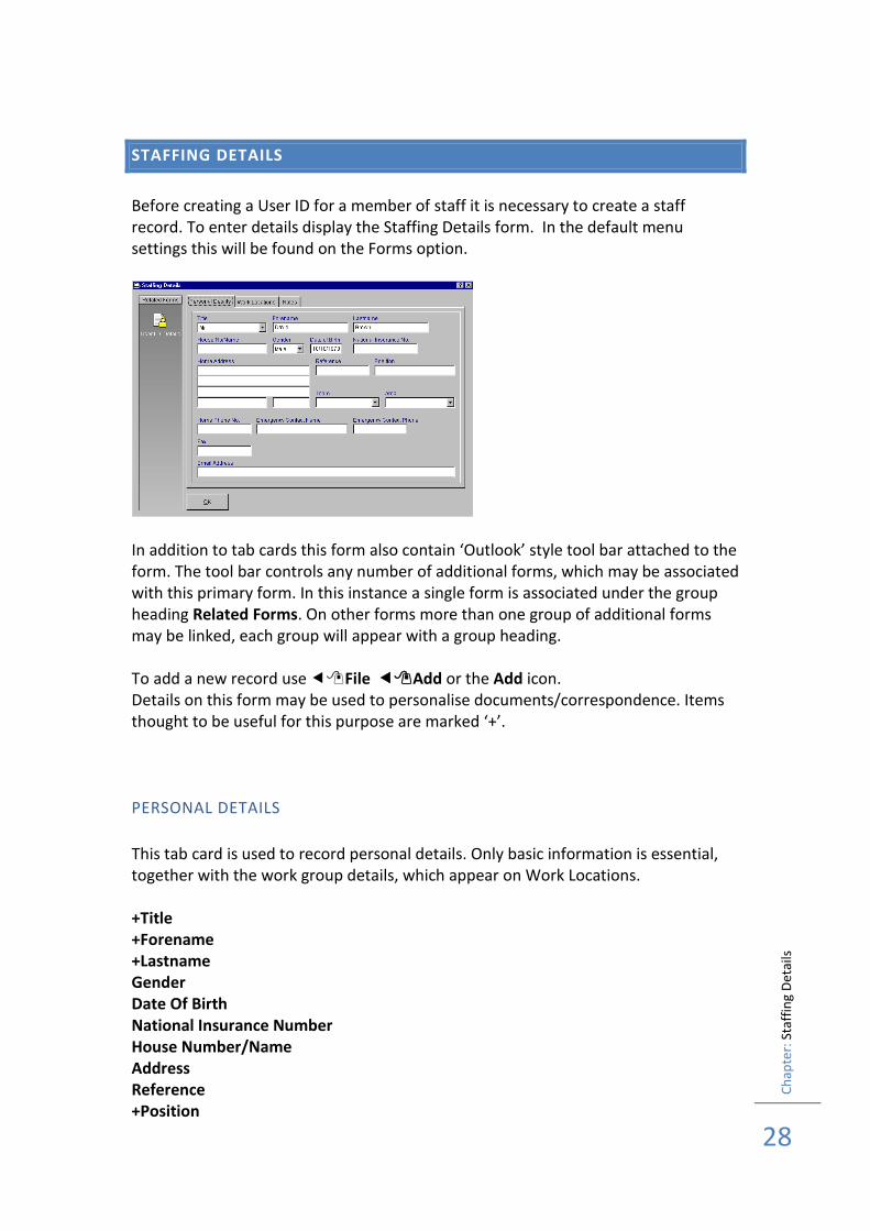
STAFFING DETAILS
Before creating a User ID for a member of staff it is necessary to create a staff record. To enter details display the Staffing Details form. In the default menu settings this will be found on the Forms option.
In addition to tab cards this form also contain ‘Outlook’ style tool bar attached to the form. The tool bar controls any number of additional forms, which may be associated with this primary form. In this instance a single form is associated under the group heading Related Forms. On other forms more than one group of additional forms may be linked, each group will appear with a group heading. To add a new record use File Add or the Add icon. Details on this form may be used to personalise documents/correspondence. Items thought to be useful for this purpose are marked ‘+’.
PERSONAL DETAILS
This tab card is used to record personal details. Only basic information is essential, together with the work group details, which appear on Work Locations. +Title +Forename +Lastname Gender Date Of Birth National Insurance Number House Number/Name Address Reference +Position
Ch
apte
r: S
taff
ing
Det
ails
29
+Team +District/Area Home Phone Number Emergency Contact Name Emergency Contact Phone Phone Fax E-Mail Exclude From Worker List This means that the individual details will not be included in the drop list of names of social workers etc for case allocation Update Allocation Details will change allocation details to reflect revised information entered on the staffing details form e.g. change of worker name
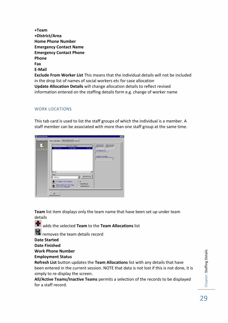
WORK LOCATIONS
This tab card is used to list the staff groups of which the individual is a member. A staff member can be associated with more than one staff group at the same time.
Team list item displays only the team name that have been set up under team details
adds the selected Team to the Team Allocations list
removes the team details record Date Started Date Finished Work Phone Number Employment Status Refresh List button updates the Team Allocations list with any details that have been entered in the current session. NOTE that data is not lost if this is not done, it is simply to re-display the screen. All/Active Teams/Inactive Teams permits a selection of the records to be displayed for a staff record.

Ch
apte
r: S
taff
ing
Det
ails
30
NOTES
This tab card is used to record any free text notes required.

Ch
apte
r: S
taff
ing
Det
ails
31
Ch
apte
r: U
ser
ID D
etai
ls
32
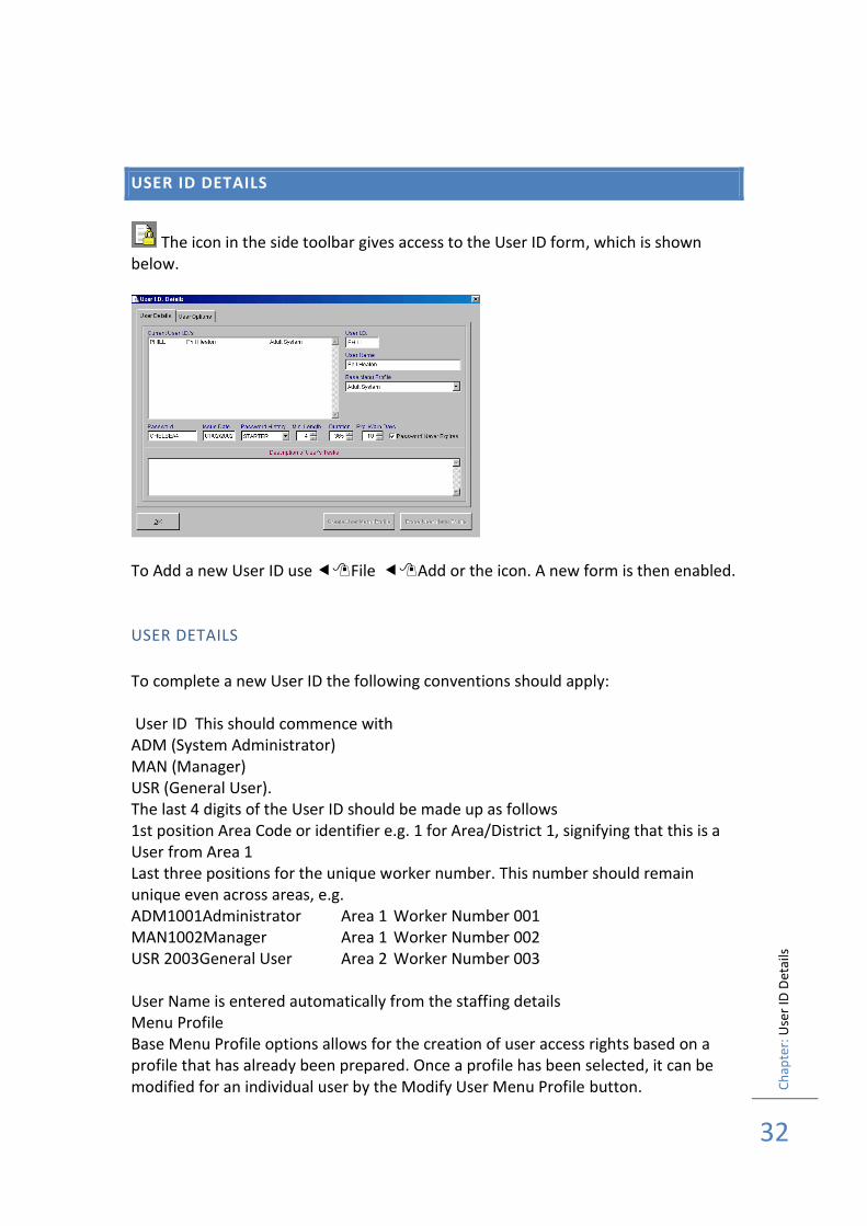
USER ID DETAILS
The icon in the side toolbar gives access to the User ID form, which is shown below.
To Add a new User ID use File Add or the icon. A new form is then enabled.
USER DETAILS
To complete a new User ID the following conventions should apply: User ID This should commence with ADM (System Administrator) MAN (Manager) USR (General User). The last 4 digits of the User ID should be made up as follows 1st position Area Code or identifier e.g. 1 for Area/District 1, signifying that this is a User from Area 1 Last three positions for the unique worker number. This number should remain unique even across areas, e.g. ADM1001Administrator Area 1 Worker Number 001 MAN1002Manager Area 1 Worker Number 002 USR 2003General User Area 2 Worker Number 003 User Name is entered automatically from the staffing details Menu Profile Base Menu Profile options allows for the creation of user access rights based on a profile that has already been prepared. Once a profile has been selected, it can be modified for an individual user by the Modify User Menu Profile button.
Ch
apte
r: U
ser
ID D
etai
ls
33
Password The password is automatically assigned to STARTER for a new user. This means that on the first time of entry using this new user ID the user will be prompted automatically to change their password. The display of the password is a system option setting between displayed/not displayed. Issue Date This is the date on which this user account was created. Your computer will automatically assign today’s date to this item. It can be changed however, by simply typing over the information already present. Password History This maintains a list of previous passwords used by the user. It prevents the user from using the same password twice. There is the option of using on this field, which will allow the systems administrator to clear the password list for a given user. Min Length This feature allows you to determine the minimum length of a password. Internal auditors often require this with systems involving payments. If in doubt please seek the advice of Internal Audit. The minimum length is 1 and the maximum is 10. To change the length either type in a new number or use the spinner on the
right hand side of the number Up arrow increases the number of characters, down arrow reduces. Duration This is the maximum period of time between password changes. During the expiry period of their password, users will be given a reminder to change their password each time they ‘sign in’. Exp Warn Days determines the number of days warning a user is given of their password expiry. The default setting is 21 days. Password Never Expires This option has been included so that at least one User ID will always be available for logging onto the application.
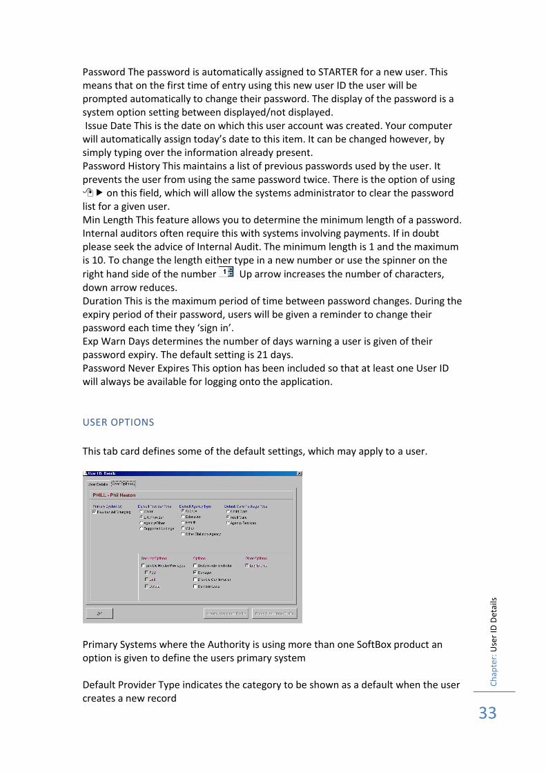
USER OPTIONS
This tab card defines some of the default settings, which may apply to a user.
Primary Systems where the Authority is using more than one SoftBox product an option is given to define the users primary system Default Provider Type indicates the category to be shown as a default when the user creates a new record
Ch
apte
r: U
ser
ID D
etai
ls
34
Default Agency Type indicates the category to be shown as a default when the user creates a new record Default Package Type indicates the category to be shown as a default when the user creates a new record
SECURITY OPTIONS
Enable Master Privileges allows the user id to override any add/edit/delete privileges that may be associated with the menu profile that has been linked to this user id Own Records Only will restrict the user to only records that they have created
OPTIONS
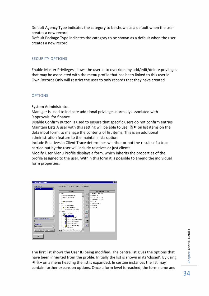
System Administrator Manager is used to indicate additional privileges normally associated with ‘approvals’ for finance. Disable Confirm Button is used to ensure that specific users do not confirm entries Maintain Lists A user with this setting will be able to use on list items on the data input form, to manage the contents of list items. This is an additional administration feature to the maintain lists option. Include Relatives in Client Trace determines whether or not the results of a trace carried out by the user will include relatives or just clients Modify User Menu Profile displays a form, which inherits the properties of the profile assigned to the user. Within this form it is possible to amend the individual form properties.
The first list shows the User ID being modified. The centre list gives the options that have been inherited from the profile. Initially the list is shown in its ‘closed’. By using + on a menu heading the list is expanded. In certain instances the list may contain further expansion options. Once a form level is reached, the form name and
Ch
apte
r: U
ser
ID D
etai
ls
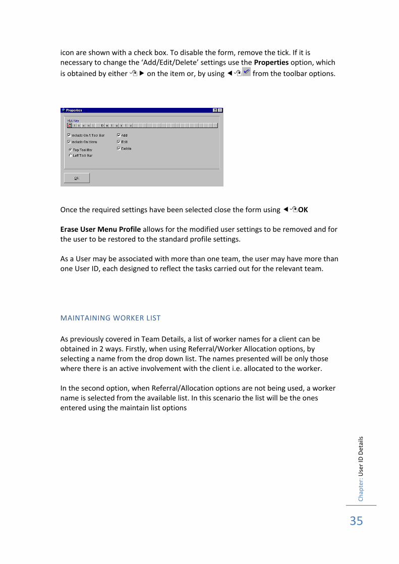
35
icon are shown with a check box. To disable the form, remove the tick. If it is necessary to change the ‘Add/Edit/Delete’ settings use the Properties option, which
is obtained by either on the item or, by using from the toolbar options.
Once the required settings have been selected close the form using OK Erase User Menu Profile allows for the modified user settings to be removed and for the user to be restored to the standard profile settings. As a User may be associated with more than one team, the user may have more than one User ID, each designed to reflect the tasks carried out for the relevant team.
MAINTAINING WORKER LIST
As previously covered in Team Details, a list of worker names for a client can be obtained in 2 ways. Firstly, when using Referral/Worker Allocation options, by selecting a name from the drop down list. The names presented will be only those where there is an active involvement with the client i.e. allocated to the worker. In the second option, when Referral/Allocation options are not being used, a worker name is selected from the available list. In this scenario the list will be the ones entered using the maintain list options

Ch
apte
r: R
ese
t U
sers
Lo
gged
On
36
RESET USERS LOGGED ON
It may be necessary to reset a User Id as a result of 3 failed access attempts. Should this be required an option is provided within the Administration menu options. Having displayed the form, highlight the required User ID using left mouse button and then use the Reset button that will have become enabled.
In addition to a simple reset Terminate User Session allows the administrator to end a user session. The current form is displayed along with the User ID details so that screen activity can be seen Send Message enables a screen message to displayed on the users screen Reset Password resets the selected user ID password back to STARTER. This is useful when a user has forgotten their password and passwords are not displayed in the Staffing record.

Ch
apte
r: R
ese
t U
sers
Lo
gged
On
37
Ch
apte
r: D
ata
Gro
up
s
38
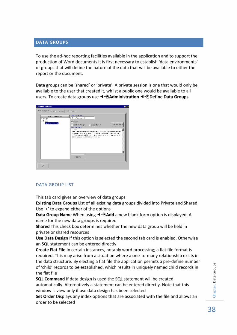
DATA GROUPS
To use the ad-hoc reporting facilities available in the application and to support the production of Word documents it is first necessary to establish ‘data environments’ or groups that will define the nature of the data that will be available to either the report or the document. Data groups can be ‘shared’ or ‘private’. A private session is one that would only be available to the user that created it, whilst a public one would be available to all users. To create data groups use Administration Define Data Groups.
DATA GROUP LIST
This tab card gives an overview of data groups Existing Data Groups List of all existing data groups divided into Private and Shared. Use ‘+’ to expand either of the options Data Group Name When using Add a new blank form option is displayed. A name for the new data groups is required Shared This check box determines whether the new data group will be held in private or shared resources Use Data Design If this option is selected the second tab card is enabled. Otherwise an SQL statement can be entered directly Create Flat File In certain instances, notably word processing; a flat file format is required. This may arise from a situation where a one-to-many relationship exists in the data structure. By electing a flat file the application permits a pre-define number of ‘child’ records to be established, which results in uniquely named child records in the flat file SQL Command If data design is used the SQL statement will be created automatically. Alternatively a statement can be entered directly. Note that this window is view only if use data design has been selected Set Order Displays any index options that are associated with the file and allows an order to be selected
Ch
apte
r: D
ata
Gro
up
s
39
Test Data Group This displays a window with sample data from the query displayed
DATA GROUP DESIGN – TABLES
Available Tables This displays a list of all tables that have been made available to the data group manager. Highlight files using and then use the navigation buttons to move files from the left window to the selected files window on the right Selected Tables This list shows all files that have been selected. The order of the files for relationships may be moved using the button to the left of the file name and sliding the file to its required position
DATA GROUP DESIGN – FIELDS
Available Fields The files selected are displayed. Each file can be expanded using ‘+’ and individual fields can be selected using and then using the navigation buttons that are positioned between the two windows Selected Fields The fields that have been selected for the query are displayed
DATA GROUP DESIGN – JOINS
Option not available at present. Contact SoftBox Support for further information
DATA GROUP DESIGN – FILTERS
Option not available at present. Contact SoftBox Support for further information
DATA GROUP DESIGN – ORDERS
Available Fields A list of previously selected fields is displayed. To select a field using and then using the navigation buttons that are positioned between the two windows Order By Fields This displays a list of fields that have been selected for ordering data
DATA GROUP DESIGN - GROUPING
Available Fields A list of previously selected fields is displayed. To select a field using and then using the navigation buttons that are positioned between the two windows
Ch
apte
r: D
ata
Gro
up
s
40
Group By Fields This displays a list of fields that have been selected for grouping data
FLAT FILE OPTIONS
This tab card is used to convert one-to-many data sets into a flat file. Data Group Fields This is a list of all fields that have been set up in the query Normalised The check box is used to select a field that needs to be converted to flat format. Once this check box has been selected a maximum limit can be set Group If the fields are required to be grouped then using this check box add the field to the Grouping Field Order window Normalised Field (Max) This sets the upper limit for the number of flat records to be created from a one-to-many relationship

Ch
apte
r: D
ata
Gro
up
s
41
Ch
apte
r: Q
uic
k Q
uer
y
42
QUICK QUERY
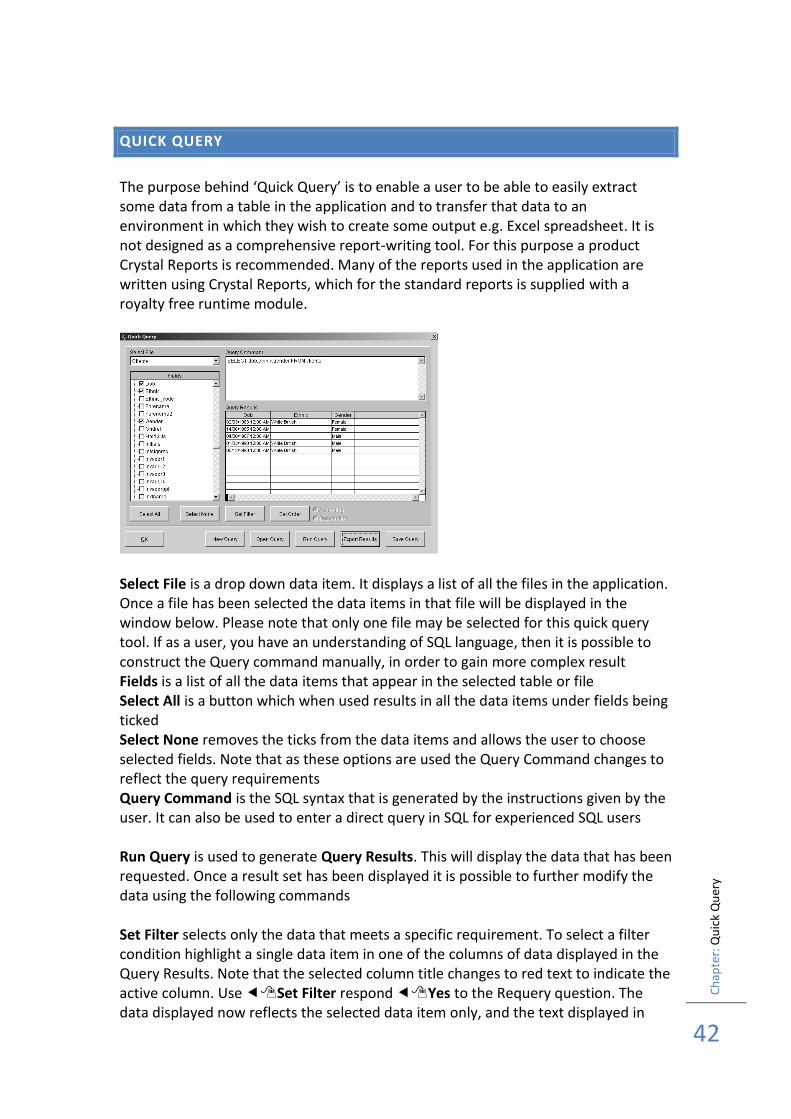
The purpose behind ‘Quick Query’ is to enable a user to be able to easily extract some data from a table in the application and to transfer that data to an environment in which they wish to create some output e.g. Excel spreadsheet. It is not designed as a comprehensive report-writing tool. For this purpose a product Crystal Reports is recommended. Many of the reports used in the application are written using Crystal Reports, which for the standard reports is supplied with a royalty free runtime module.
Select File is a drop down data item. It displays a list of all the files in the application. Once a file has been selected the data items in that file will be displayed in the window below. Please note that only one file may be selected for this quick query tool. If as a user, you have an understanding of SQL language, then it is possible to construct the Query command manually, in order to gain more complex result Fields is a list of all the data items that appear in the selected table or file Select All is a button which when used results in all the data items under fields being ticked Select None removes the ticks from the data items and allows the user to choose selected fields. Note that as these options are used the Query Command changes to reflect the query requirements Query Command is the SQL syntax that is generated by the instructions given by the user. It can also be used to enter a direct query in SQL for experienced SQL users Run Query is used to generate Query Results. This will display the data that has been requested. Once a result set has been displayed it is possible to further modify the data using the following commands Set Filter selects only the data that meets a specific requirement. To select a filter condition highlight a single data item in one of the columns of data displayed in the Query Results. Note that the selected column title changes to red text to indicate the active column. Use Set Filter respond Yes to the Requery question. The data displayed now reflects the selected data item only, and the text displayed in
Ch
apte
r: Q
uic
k Q
uer
y
43
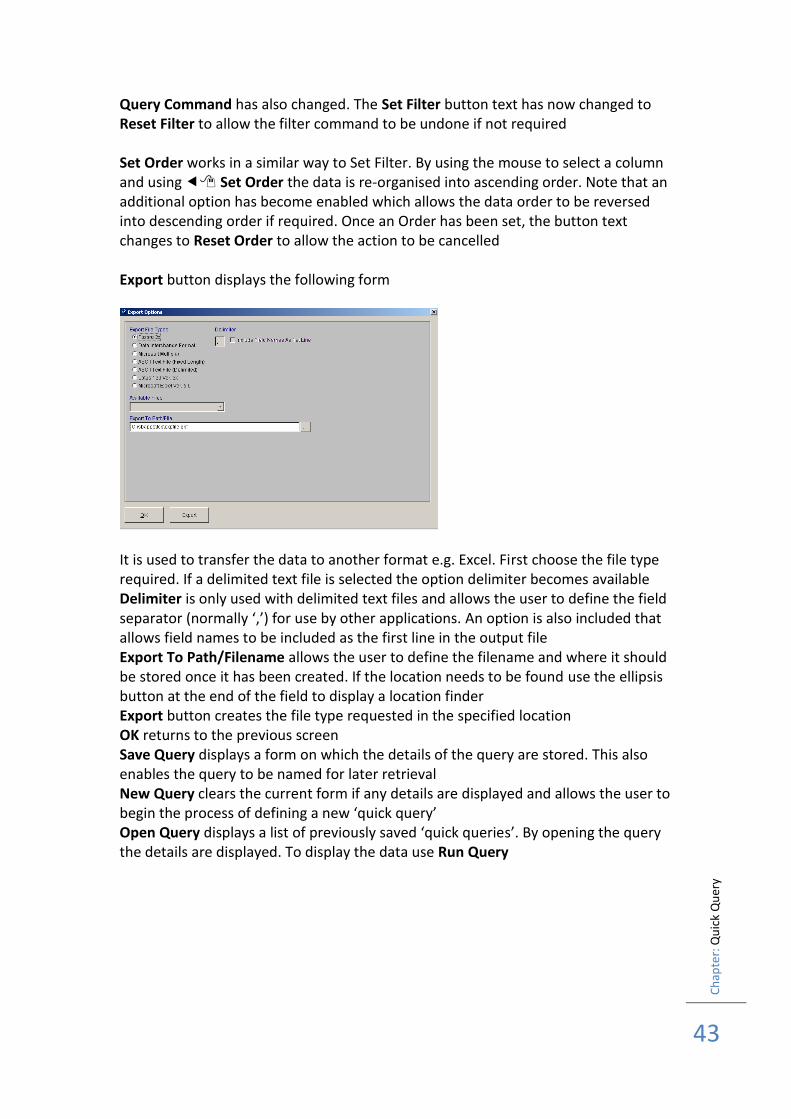
Query Command has also changed. The Set Filter button text has now changed to Reset Filter to allow the filter command to be undone if not required Set Order works in a similar way to Set Filter. By using the mouse to select a column and using Set Order the data is re-organised into ascending order. Note that an additional option has become enabled which allows the data order to be reversed into descending order if required. Once an Order has been set, the button text changes to Reset Order to allow the action to be cancelled Export button displays the following form
It is used to transfer the data to another format e.g. Excel. First choose the file type required. If a delimited text file is selected the option delimiter becomes available Delimiter is only used with delimited text files and allows the user to define the field separator (normally ‘,’) for use by other applications. An option is also included that allows field names to be included as the first line in the output file Export To Path/Filename allows the user to define the filename and where it should be stored once it has been created. If the location needs to be found use the ellipsis button at the end of the field to display a location finder Export button creates the file type requested in the specified location OK returns to the previous screen Save Query displays a form on which the details of the query are stored. This also enables the query to be named for later retrieval New Query clears the current form if any details are displayed and allows the user to begin the process of defining a new ‘quick query’ Open Query displays a list of previously saved ‘quick queries’. By opening the query the details are displayed. To display the data use Run Query
Ch
apte
r: A
pp
licat
ion
Hel
p
44
APPLICATION HELP
F1 HELP
This Help options requires Internet Explorer. A copy of the installation for Internet Explorer is enclosed on the installation CD. The F1 key displays a help page for the form that is displayed on screen. If there are links to other help pages e.g. Training instructions then this will be shown as a hyperlink called ‘Training Link’.

Ch
apte
r: A
pp
licat
ion
Hel
p
45
Ch
apte
r: F
inan
ce
46
FINANCE
This application uses a generic module for the creation, maintenance and management of issues associated with Finance. This is includes transaction files, budgets and the releasing of transaction files for payment. To be able to use these features it is first necessary to create a menu profile based on the Finance template. Further information on this can be found in the Administration section of this User Documentation or in the Training Guide worked examples. Once a user has logged on with this new profile the remaining topics in this section will be available.

Ch
apte
r: F
inan
ce
47

Ch
apte
r: B
ud
get
Mai
nte
nan
ce
48
BUDGET MAINTENANCE
This form is used to define Budget Amounts associated with individual budget lines. These budget lines are made up by selecting one part from each of the elements in the budget structure. Before this option may be used it is necessary to have Defined the number of elements in the Budget Code structure and labelled then with the local terminology. (See System Options) Set up the list items that will be used for account codes (See Maintaining Lists in Administration User Guide) Once these steps have been completed, budget lines can be established.
Budget lines are entered by using Forms Budget Forecast Maintenance to display the form. Each budget line is then entered by using ‘+’ from the left-hand toolbar and selecting from the drop down lists the appropriate code. The code list that appears is the one that was defined in lists maintenance, together with any description that may have been entered at the time. At the end of each line the budget allocation is entered. When all budget lines have been created use OK to close the form.

Ch
apte
r: B
ud
get
Mai
nte
nan
ce
49
Ch
apte
r: A
cco
un
t C
od
es
50
ACCOUNT CODES
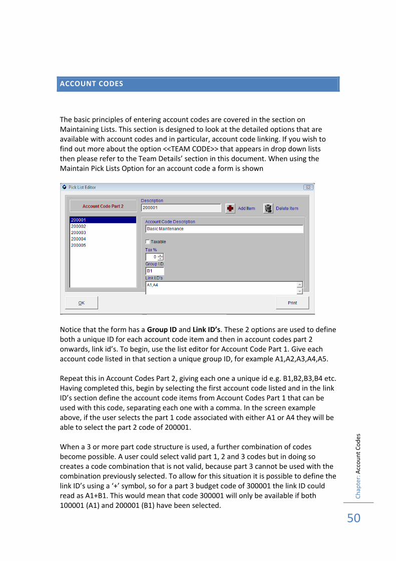
The basic principles of entering account codes are covered in the section on Maintaining Lists. This section is designed to look at the detailed options that are available with account codes and in particular, account code linking. If you wish to find out more about the option <<TEAM CODE>> that appears in drop down lists then please refer to the Team Details’ section in this document. When using the Maintain Pick Lists Option for an account code a form is shown
Notice that the form has a Group ID and Link ID’s. These 2 options are used to define both a unique ID for each account code item and then in account codes part 2 onwards, link id’s. To begin, use the list editor for Account Code Part 1. Give each account code listed in that section a unique group ID, for example A1,A2,A3,A4,A5. Repeat this in Account Codes Part 2, giving each one a unique id e.g. B1,B2,B3,B4 etc. Having completed this, begin by selecting the first account code listed and in the link ID’s section define the account code items from Account Codes Part 1 that can be used with this code, separating each one with a comma. In the screen example above, if the user selects the part 1 code associated with either A1 or A4 they will be able to select the part 2 code of 200001. When a 3 or more part code structure is used, a further combination of codes become possible. A user could select valid part 1, 2 and 3 codes but in doing so creates a code combination that is not valid, because part 3 cannot be used with the combination previously selected. To allow for this situation it is possible to define the link ID’s using a ‘+’ symbol, so for a part 3 budget code of 300001 the link ID could read as A1+B1. This would mean that code 300001 will only be available if both 100001 (A1) and 200001 (B1) have been selected.

Ch
apte
r: A
cco
un
t C
od
es
51
Ch
apte
r: T
ran
sact
ion
File
s
52
TRANSACTION FILES
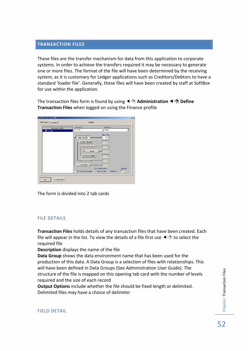
These files are the transfer mechanism for data from this application to corporate systems. In order to achieve the transfers required it may be necessary to generate one or more files. The format of the file will have been determined by the receiving system, as it is customary for Ledger applications such as Creditors/Debtors to have a standard ‘loader file’. Generally, these files will have been created by staff at SoftBox for use within the application. The transaction files form is found by using Administration Define Transaction Files when logged on using the Finance profile
The form is divided into 2 tab cards
FILE DETAILS
Transaction Files holds details of any transaction files that have been created. Each file will appear in the list. To view the details of a file first use to select the required file Description displays the name of the file Data Group shows the data environment name that has been used for the production of this data. A Data Group is a selection of files with relationships. This will have been defined in Data Groups (See Administration User Guide). The structure of the file is mapped on this opening tab card with the number of levels required and the size of each record Output Options include whether the file should be fixed length or delimited. Delimited files may have a choice of delimiter
FIELD DETAIL

Ch
apte
r: T
ran
sact
ion
File
s
53
This tab card shows the contents of each level in the file
The contents of each block type can be defined, with additional fields being created from within the original data. This allows for fields to be combined in order to meet requirements. The appearance of individual fields can be changed e.g. leading zeros and upper case fonts. Once the file has been created it is run by using the Transaction File options in the appropriate payments procedure. As this is a generic facility any number of files may be set up for use within different procedures e.g. creditors and debtors files. Precisely which file(s) is executed in a particular payment or billing procedure will be determined by the options chosen in the System Settings
Ch
apte
r: R
elea
sin
g Tr
ansa
ctio
n F
iles
54
RELEASING TRANSACTION FILES
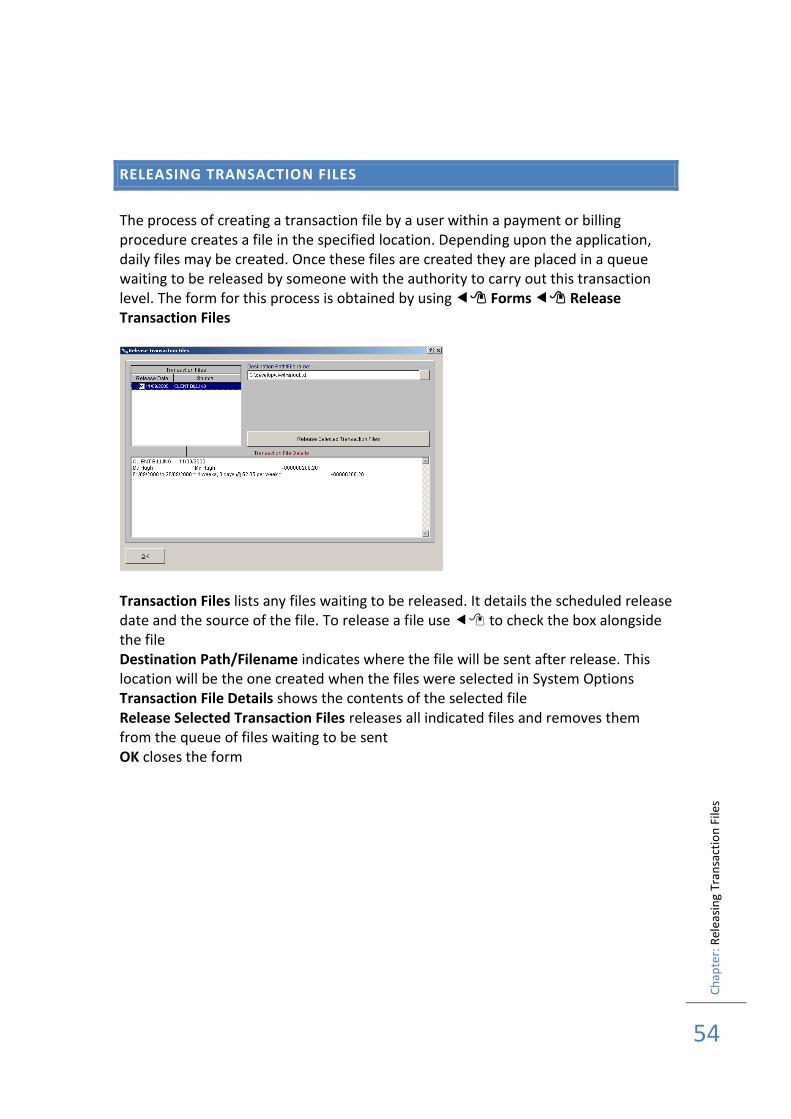
The process of creating a transaction file by a user within a payment or billing procedure creates a file in the specified location. Depending upon the application, daily files may be created. Once these files are created they are placed in a queue waiting to be released by someone with the authority to carry out this transaction level. The form for this process is obtained by using Forms Release Transaction Files
Transaction Files lists any files waiting to be released. It details the scheduled release date and the source of the file. To release a file use to check the box alongside the file Destination Path/Filename indicates where the file will be sent after release. This location will be the one created when the files were selected in System Options Transaction File Details shows the contents of the selected file Release Selected Transaction Files releases all indicated files and removes them from the queue of files waiting to be sent OK closes the form

Ch
apte
r: R
elea
sin
g Tr
ansa
ctio
n F
iles
55
Ch
apte
r: D
elet
ing
Re
cord
s
56
DELETING RECORDS
As a result of entering ‘Delete Date’ on a client’s basic details, records will become due for deletion. A delete date will also be entered against a client form that has been deleted by a user, although this record will not be visible to users after it has been deleted. Before records can be removed it will be necessary to complete a number of procedures. To carry out these procedures the user will need to be logged on as the administrator using the STARTER logon.
ADMINISTRATION/ ADMINISTRATION REPORTS/CLIENT DELETIONS LOG
This report produces a list of all records that have a delete date, either because the record is due to expire or because a user has deleted the record. The list must be printed before running the remaining procedures otherwise no records will be removed.
ADMINISTRATION/REMOVE DELETED RECORDS
This option removes client records from view in line with the client details that had been printed previously using the report option above.
ADMINISTRATION/REMOVE SUB RECORDS
Once the primary client form has been deleted the remaining records that were linked to the client form can be removed by using this final option.

Ch
apte
r: D
elet
ing
Re
cord
s
57
Ch
apte
r: F
ield
Lev
el P
rop
erti
es
58
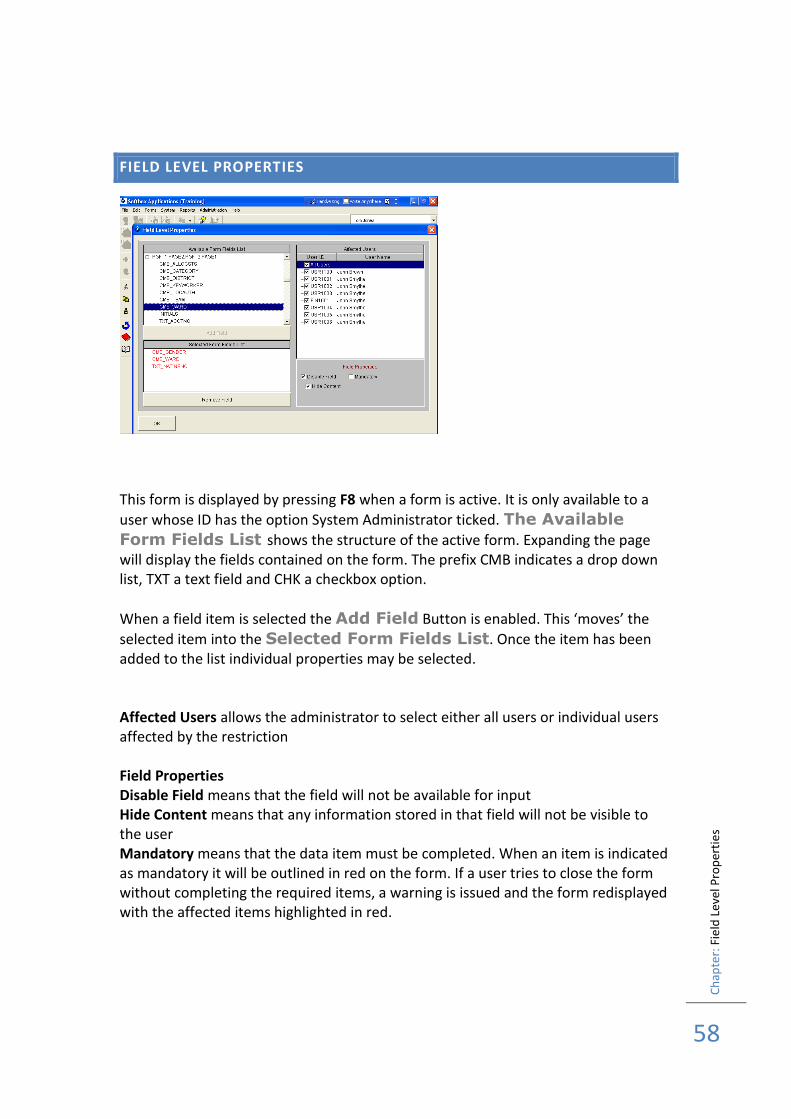
FIELD LEVEL PROPERTIES
This form is displayed by pressing F8 when a form is active. It is only available to a
user whose ID has the option System Administrator ticked. The Available
Form Fields List shows the structure of the active form. Expanding the page will display the fields contained on the form. The prefix CMB indicates a drop down list, TXT a text field and CHK a checkbox option.
When a field item is selected the Add Field Button is enabled. This ‘moves’ the
selected item into the Selected Form Fields List. Once the item has been added to the list individual properties may be selected. Affected Users allows the administrator to select either all users or individual users affected by the restriction Field Properties Disable Field means that the field will not be available for input Hide Content means that any information stored in that field will not be visible to the user Mandatory means that the data item must be completed. When an item is indicated as mandatory it will be outlined in red on the form. If a user tries to close the form without completing the required items, a warning is issued and the form redisplayed with the affected items highlighted in red.

Ch
apte
r: F
ield
Lev
el P
rop
erti
es
59
Ch
apte
r: R
eco
rd M
aski
ng
60
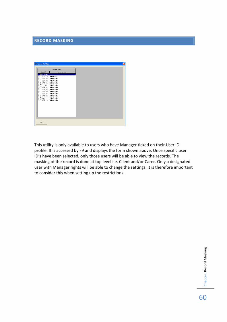
RECORD MASKING
This utility is only available to users who have Manager ticked on their User ID profile. It is accessed by F9 and displays the form shown above. Once specific user ID’s have been selected, only those users will be able to view the records. The masking of the record is done at top level i.e. Client and/or Carer. Only a designated user with Manager rights will be able to change the settings. It is therefore important to consider this when setting up the restrictions.

Ch
apte
r: R
eco
rd M
aski
ng
61
Ch
apte
r: A
dm
inis
trat
ion
Mo
du
le F
un
ctio
nal
Sp
ecif
icat
ion
62
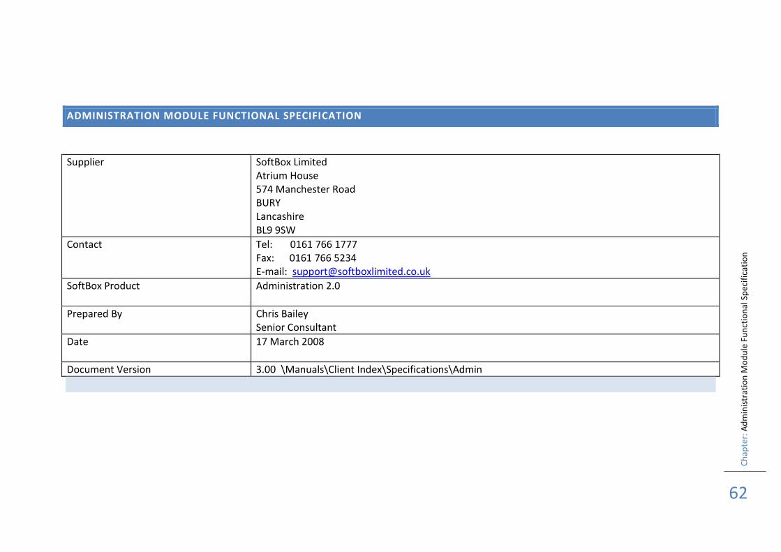
ADMINISTRATION MODULE FUNCTIONAL SPECIFICATION
Supplier SoftBox Limited Atrium House 574 Manchester Road BURY Lancashire BL9 9SW
Contact Tel: 0161 766 1777 Fax: 0161 766 5234 E-mail: [email protected]
SoftBox Product Administration 2.0
Prepared By Chris Bailey Senior Consultant
Date 17 March 2008
Document Version 3.00 \Manuals\Client Index\Specifications\Admin
Ch
apte
r: A
dm
inis
trat
ion
Mo
du
le F
un
ctio
nal
Sp
ecif
icat
ion
63
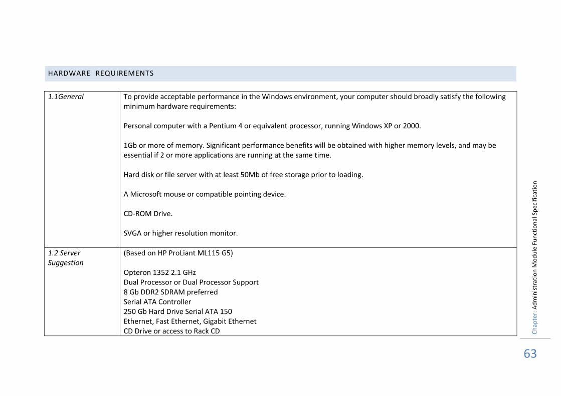
HARDWARE REQUIREMENTS
1.1General
To provide acceptable performance in the Windows environment, your computer should broadly satisfy the following minimum hardware requirements: Personal computer with a Pentium 4 or equivalent processor, running Windows XP or 2000. 1Gb or more of memory. Significant performance benefits will be obtained with higher memory levels, and may be essential if 2 or more applications are running at the same time. Hard disk or file server with at least 50Mb of free storage prior to loading. A Microsoft mouse or compatible pointing device. CD-ROM Drive. SVGA or higher resolution monitor.
1.2 Server Suggestion
(Based on HP ProLiant ML115 G5) Opteron 1352 2.1 GHz Dual Processor or Dual Processor Support 8 Gb DDR2 SDRAM preferred Serial ATA Controller 250 Gb Hard Drive Serial ATA 150 Ethernet, Fast Ethernet, Gigabit Ethernet CD Drive or access to Rack CD
Ch
apte
r: A
dm
inis
trat
ion
Mo
du
le F
un
ctio
nal
Sp
ecif
icat
ion
64
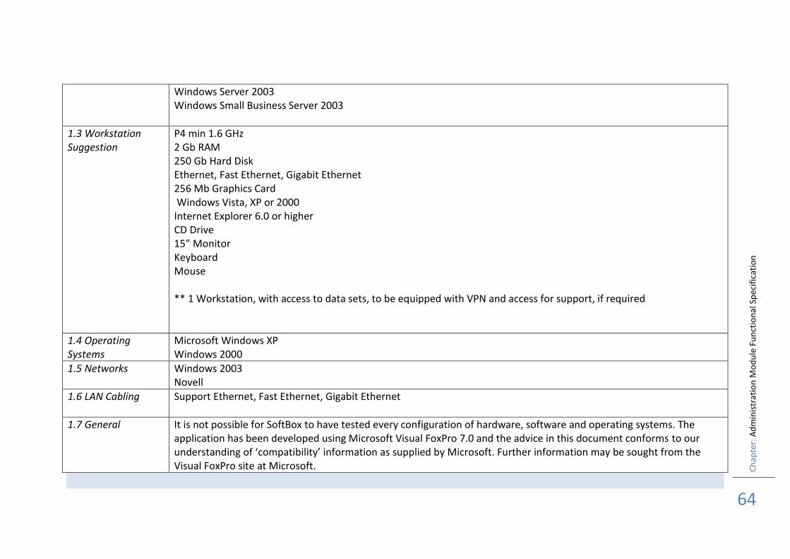
Windows Server 2003 Windows Small Business Server 2003
1.3 Workstation Suggestion
P4 min 1.6 GHz 2 Gb RAM 250 Gb Hard Disk Ethernet, Fast Ethernet, Gigabit Ethernet 256 Mb Graphics Card Windows Vista, XP or 2000 Internet Explorer 6.0 or higher CD Drive 15” Monitor Keyboard Mouse ** 1 Workstation, with access to data sets, to be equipped with VPN and access for support, if required
1.4 Operating Systems
Microsoft Windows XP Windows 2000
1.5 Networks Windows 2003 Novell
1.6 LAN Cabling Support Ethernet, Fast Ethernet, Gigabit Ethernet
1.7 General It is not possible for SoftBox to have tested every configuration of hardware, software and operating systems. The application has been developed using Microsoft Visual FoxPro 7.0 and the advice in this document conforms to our understanding of ‘compatibility’ information as supplied by Microsoft. Further information may be sought from the Visual FoxPro site at Microsoft.

Ch
apte
r: A
dm
inis
trat
ion
Mo
du
le F
un
ctio
nal
Sp
ecif
icat
ion
65
APPLICATION ENVIRONMENT
2.1. Overview The application has been designed to be used a either a stand-alone application or for use over networks. Appropriate record handling facilities have been included to enable ‘multi-user’.
2.2 Installation Installation is from a self-running CD. A utility is provided which allows for the data to be located on a server. For this type of installation it is important that any server location is mapped to the individual PC before configuring the application set up. The application is supplied with ‘run time’ files. No other software is required to run the application. Internet Explorer 5.0 or higher will be required for both the installation and F1 help.
2.3. Data Handling and Reporting
2.3.1. Data Import Data can be imported from other applications, if this data is supplied in standard ASCII comma delimited format. SoftBox will write the necessary programs to enable the data to be loaded as a ‘one-off’ operation
2.3.2. Data Links A link can be created between SoftBox Applications and other applications, which are ODBC compliant. This would be customised to the requirements of the individual Local Authority
2.3.3. Reporting Tools
A range of standard reports are included. In addition the product is ODBC compliant and can therefore be used with additional reporting tools e.g. Crystal Reports Professional Edition
2.3.4. Databases The application is written using Visual FoxPro 7.0 from Microsoft. It uses the .dbf file formats supplied with Visual FoxPro in a ‘container’ file .dbc, which is ODBC compliant.
2.3.5 Other Software dependencies
SoftBox applications use members of the Microsoft Office products for the production of standard documentation (Word) and reporting (Excel). Both versions of this software must be Version 6.0 or higher as support for Visual Basic commands
Ch
apte
r: A
dm
inis
trat
ion
Mo
du
le F
un
ctio
na
l Sp
ecif
icat
ion
66
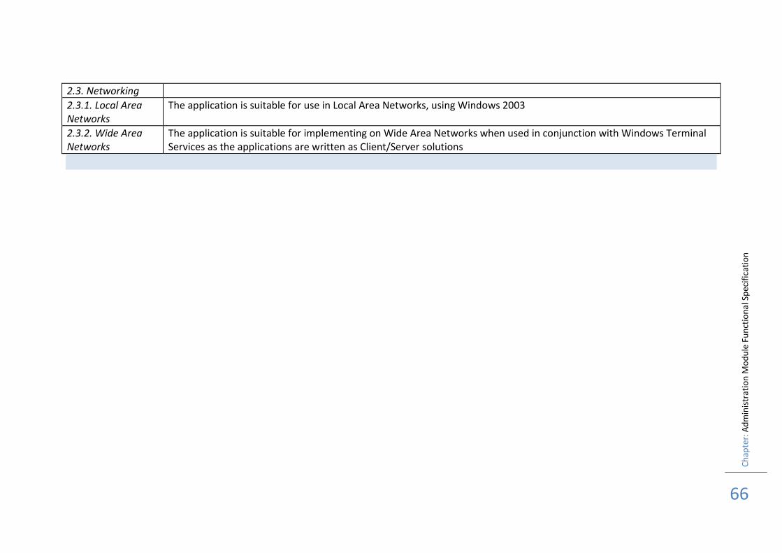
2.3. Networking
2.3.1. Local Area Networks
The application is suitable for use in Local Area Networks, using Windows 2003
2.3.2. Wide Area Networks
The application is suitable for implementing on Wide Area Networks when used in conjunction with Windows Terminal Services as the applications are written as Client/Server solutions
Ch
apte
r: A
dm
inis
trat
ion
Mo
du
le F
un
ctio
nal
Sp
ecif
icat
ion
67
APPLICATION SECURITY
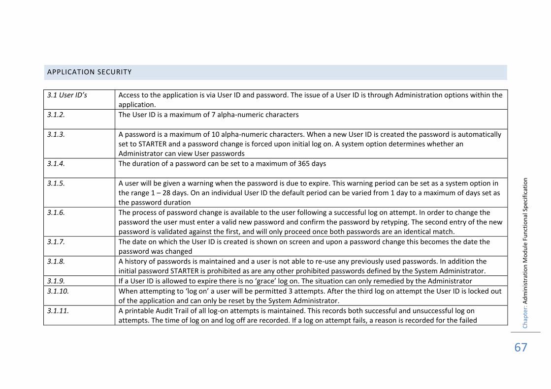
3.1 User ID’s Access to the application is via User ID and password. The issue of a User ID is through Administration options within the application.
3.1.2. The User ID is a maximum of 7 alpha-numeric characters
3.1.3. A password is a maximum of 10 alpha-numeric characters. When a new User ID is created the password is automatically set to STARTER and a password change is forced upon initial log on. A system option determines whether an Administrator can view User passwords
3.1.4. The duration of a password can be set to a maximum of 365 days
3.1.5. A user will be given a warning when the password is due to expire. This warning period can be set as a system option in the range 1 – 28 days. On an individual User ID the default period can be varied from 1 day to a maximum of days set as the password duration
3.1.6. The process of password change is available to the user following a successful log on attempt. In order to change the password the user must enter a valid new password and confirm the password by retyping. The second entry of the new password is validated against the first, and will only proceed once both passwords are an identical match.
3.1.7. The date on which the User ID is created is shown on screen and upon a password change this becomes the date the password was changed
3.1.8. A history of passwords is maintained and a user is not able to re-use any previously used passwords. In addition the initial password STARTER is prohibited as are any other prohibited passwords defined by the System Administrator.
3.1.9. If a User ID is allowed to expire there is no ‘grace’ log on. The situation can only remedied by the Administrator
3.1.10. When attempting to ‘log on’ a user will be permitted 3 attempts. After the third log on attempt the User ID is locked out of the application and can only be reset by the System Administrator.
3.1.11. A printable Audit Trail of all log-on attempts is maintained. This records both successful and unsuccessful log on attempts. The time of log on and log off are recorded. If a log on attempt fails, a reason is recorded for the failed
Ch
apte
r: A
dm
inis
trat
ion
Mo
du
le F
un
ctio
nal
Sp
ecif
icat
ion
68
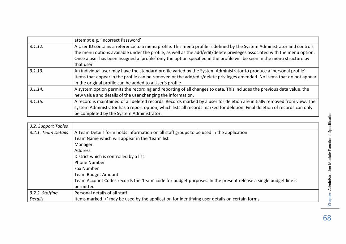
attempt e.g. ‘Incorrect Password’
3.1.12. A User ID contains a reference to a menu profile. This menu profile is defined by the System Administrator and controls the menu options available under the profile, as well as the add/edit/delete privileges associated with the menu option. Once a user has been assigned a ‘profile’ only the option specified in the profile will be seen in the menu structure by that user
3.1.13. An individual user may have the standard profile varied by the System Administrator to produce a ‘personal profile’. Items that appear in the profile can be removed or the add/edit/delete privileges amended. No items that do not appear in the original profile can be added to a User’s profile
3.1.14. A system option permits the recording and reporting of all changes to data. This includes the previous data value, the new value and details of the user changing the information.
3.1.15. A record is maintained of all deleted records. Records marked by a user for deletion are initially removed from view. The system Administrator has a report option, which lists all records marked for deletion. Final deletion of records can only be completed by the System Administrator.
3.2. Support Tables
3.2.1. Team Details A Team Details form holds information on all staff groups to be used in the application Team Name which will appear in the ‘team’ list Manager Address District which is controlled by a list Phone Number Fax Number Team Budget Amount Team Account Codes records the ‘team’ code for budget purposes. In the present release a single budget line is permitted
3.2.2. Staffing Details
Personal details of all staff. Items marked ‘+’ may be used by the application for identifying user details on certain forms
Ch
apte
r: A
dm
inis
trat
ion
Mo
du
le F
un
ctio
nal
Sp
ecif
icat
ion
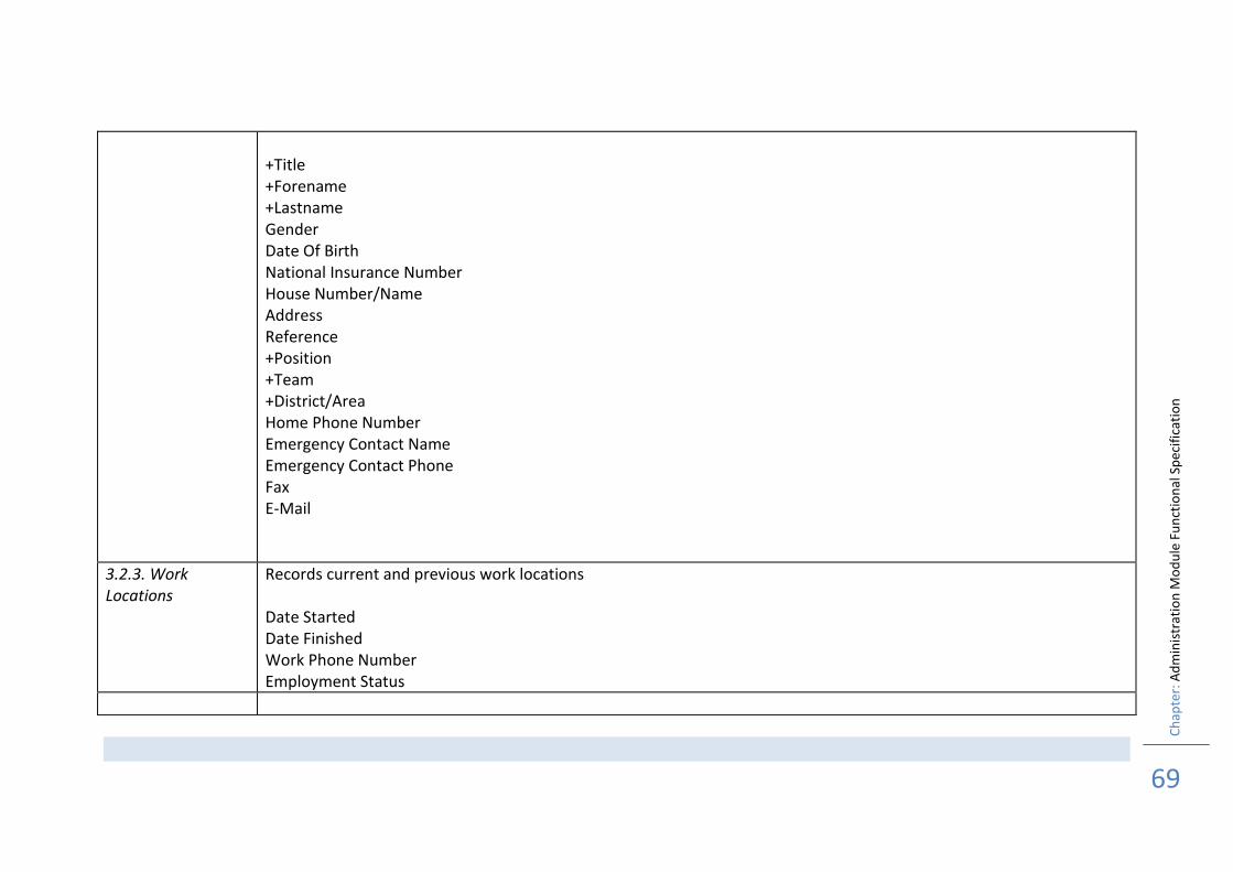
69
+Title +Forename +Lastname Gender Date Of Birth National Insurance Number House Number/Name Address Reference +Position +Team +District/Area Home Phone Number Emergency Contact Name Emergency Contact Phone Fax E-Mail
3.2.3. Work Locations
Records current and previous work locations Date Started Date Finished Work Phone Number Employment Status
Ch
apte
r: A
dm
inis
trat
ion
Mo
du
le F
un
ctio
nal
Sp
ecif
icat
ion
70
COMMON FUNCTIONS
4.1. User Interface
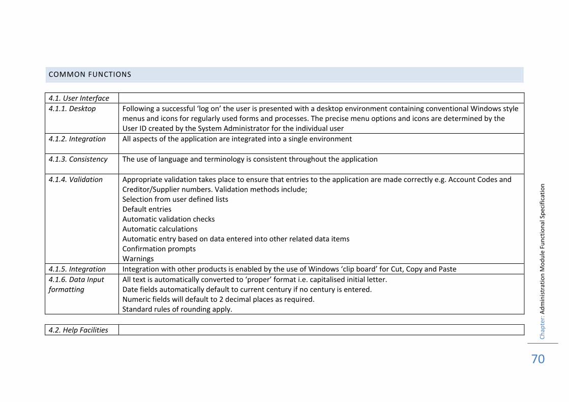
4.1.1. Desktop Following a successful ‘log on’ the user is presented with a desktop environment containing conventional Windows style menus and icons for regularly used forms and processes. The precise menu options and icons are determined by the User ID created by the System Administrator for the individual user
4.1.2. Integration All aspects of the application are integrated into a single environment
4.1.3. Consistency The use of language and terminology is consistent throughout the application
4.1.4. Validation Appropriate validation takes place to ensure that entries to the application are made correctly e.g. Account Codes and Creditor/Supplier numbers. Validation methods include; Selection from user defined lists Default entries Automatic validation checks Automatic calculations Automatic entry based on data entered into other related data items Confirmation prompts Warnings
4.1.5. Integration Integration with other products is enabled by the use of Windows ‘clip board’ for Cut, Copy and Paste
4.1.6. Data Input formatting
All text is automatically converted to ‘proper’ format i.e. capitalised initial letter. Date fields automatically default to current century if no century is entered. Numeric fields will default to 2 decimal places as required. Standard rules of rounding apply.
4.2. Help Facilities
Ch
apte
r: A
dm
inis
trat
ion
Mo
du
le F
un
ctio
nal
Sp
ecif
icat
ion
71
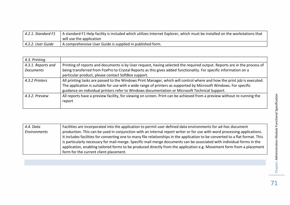
4.2.1. Standard F1 A standard F1 Help facility is included which utilizes Internet Explorer, which must be installed on the workstations that will use the application
4.2.2. User Guide A comprehensive User Guide is supplied in published form.
4.3. Printing
4.3.1. Reports and Documents
Printing of reports and documents is by User request, having selected the required output. Reports are in the process of being transferred from FoxPro to Crystal Reports as this gives added functionality. For specific information on a particular product, please contact SoftBox support.
4.3.2 Printers All printing tasks are passed to the Windows Print Manager, which will control where and how the print job is executed. The application is suitable for use with a wide range of printers as supported by Microsoft Windows. For specific guidance on individual printers refer to Windows documentation or Microsoft Technical Support.
4.3.2. Preview All reports have a preview facility, for viewing on screen. Print can be achieved from a preview without re-running the report
4.4. Data Environments
Facilities are incorporated into the application to permit user defined data environments for ad-hoc document production. This can be used in conjunction with an internal report writer or for use with word processing applications. It includes facilities for converting one to many file relationships in the application to be converted to a flat format. This is particularly necessary for mail-merge. Specific mail merge documents can be associated with individual forms in the application, enabling tailored forms to be produced directly from the application e.g. Movement form from a placement form for the current client placement.
Ch
apte
r: A
dm
inis
trat
ion
Mo
du
le F
un
ctio
nal
Sp
ecif
icat
ion
72
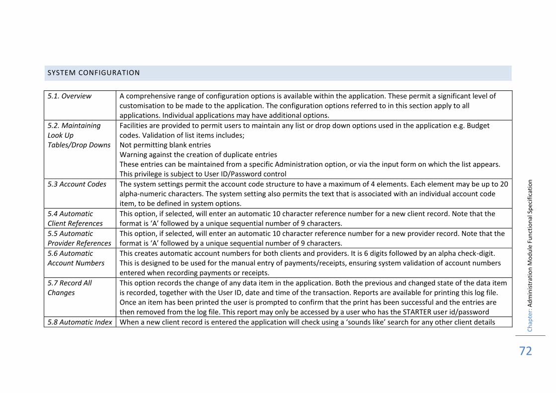
SYSTEM CONFIGURATION
5.1. Overview A comprehensive range of configuration options is available within the application. These permit a significant level of customisation to be made to the application. The configuration options referred to in this section apply to all applications. Individual applications may have additional options.
5.2. Maintaining Look Up Tables/Drop Downs
Facilities are provided to permit users to maintain any list or drop down options used in the application e.g. Budget codes. Validation of list items includes; Not permitting blank entries Warning against the creation of duplicate entries These entries can be maintained from a specific Administration option, or via the input form on which the list appears. This privilege is subject to User ID/Password control
5.3 Account Codes The system settings permit the account code structure to have a maximum of 4 elements. Each element may be up to 20 alpha-numeric characters. The system setting also permits the text that is associated with an individual account code item, to be defined in system options.
5.4 Automatic Client References
This option, if selected, will enter an automatic 10 character reference number for a new client record. Note that the format is ‘A’ followed by a unique sequential number of 9 characters.
5.5 Automatic Provider References
This option, if selected, will enter an automatic 10 character reference number for a new provider record. Note that the format is ‘A’ followed by a unique sequential number of 9 characters.
5.6 Automatic Account Numbers
This creates automatic account numbers for both clients and providers. It is 6 digits followed by an alpha check-digit. This is designed to be used for the manual entry of payments/receipts, ensuring system validation of account numbers entered when recording payments or receipts.
5.7 Record All Changes
This option records the change of any data item in the application. Both the previous and changed state of the data item is recorded, together with the User ID, date and time of the transaction. Reports are available for printing this log file. Once an item has been printed the user is prompted to confirm that the print has been successful and the entries are then removed from the log file. This report may only be accessed by a user who has the STARTER user id/password
5.8 Automatic Index When a new client record is entered the application will check using a ‘sounds like’ search for any other client details
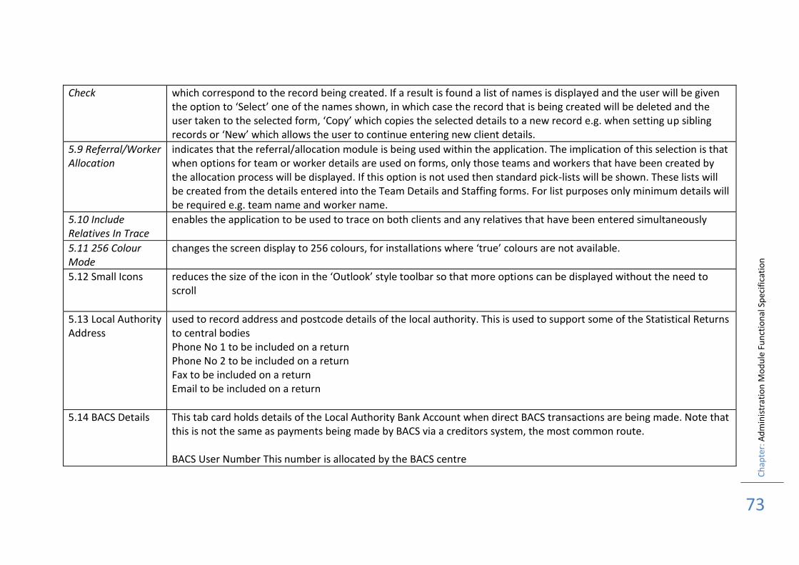
Ch
apte
r: A
dm
inis
trat
ion
Mo
du
le F
un
ctio
nal
Sp
ecif
icat
ion
73
Check which correspond to the record being created. If a result is found a list of names is displayed and the user will be given the option to ‘Select’ one of the names shown, in which case the record that is being created will be deleted and the user taken to the selected form, ‘Copy’ which copies the selected details to a new record e.g. when setting up sibling records or ‘New’ which allows the user to continue entering new client details.
5.9 Referral/Worker Allocation
indicates that the referral/allocation module is being used within the application. The implication of this selection is that when options for team or worker details are used on forms, only those teams and workers that have been created by the allocation process will be displayed. If this option is not used then standard pick-lists will be shown. These lists will be created from the details entered into the Team Details and Staffing forms. For list purposes only minimum details will be required e.g. team name and worker name.
5.10 Include Relatives In Trace
enables the application to be used to trace on both clients and any relatives that have been entered simultaneously
5.11 256 Colour Mode
changes the screen display to 256 colours, for installations where ‘true’ colours are not available.
5.12 Small Icons reduces the size of the icon in the ‘Outlook’ style toolbar so that more options can be displayed without the need to scroll
5.13 Local Authority Address
used to record address and postcode details of the local authority. This is used to support some of the Statistical Returns to central bodies Phone No 1 to be included on a return Phone No 2 to be included on a return Fax to be included on a return Email to be included on a return
5.14 BACS Details This tab card holds details of the Local Authority Bank Account when direct BACS transactions are being made. Note that this is not the same as payments being made by BACS via a creditors system, the most common route. BACS User Number This number is allocated by the BACS centre

Ch
apte
r: A
dm
inis
trat
ion
Mo
du
le F
un
ctio
na
l Sp
ecif
icat
ion
74
Sort Code of the LA account Account Number of the LA account Account Name of the LA account Bank Name where the LA account is held BACS File Destination/Path identifies the location of the output file when it is created
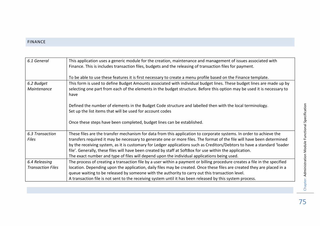
Ch
apte
r: A
dm
inis
trat
ion
Mo
du
le F
un
ctio
nal
Sp
ecif
icat
ion
75
FINANCE
6.1 General This application uses a generic module for the creation, maintenance and management of issues associated with Finance. This is includes transaction files, budgets and the releasing of transaction files for payment. To be able to use these features it is first necessary to create a menu profile based on the Finance template.
6.2 Budget Maintenance
This form is used to define Budget Amounts associated with individual budget lines. These budget lines are made up by selecting one part from each of the elements in the budget structure. Before this option may be used it is necessary to have Defined the number of elements in the Budget Code structure and labelled then with the local terminology. Set up the list items that will be used for account codes Once these steps have been completed, budget lines can be established.
6.3 Transaction Files
These files are the transfer mechanism for data from this application to corporate systems. In order to achieve the transfers required it may be necessary to generate one or more files. The format of the file will have been determined by the receiving system, as it is customary for Ledger applications such as Creditors/Debtors to have a standard ‘loader file’. Generally, these files will have been created by staff at SoftBox for use within the application. The exact number and type of files will depend upon the individual applications being used.
6.4 Releasing Transaction Files
The process of creating a transaction file by a user within a payment or billing procedure creates a file in the specified location. Depending upon the application, daily files may be created. Once these files are created they are placed in a queue waiting to be released by someone with the authority to carry out this transaction level. A transaction file is not sent to the receiving system until it has been released by this system process.
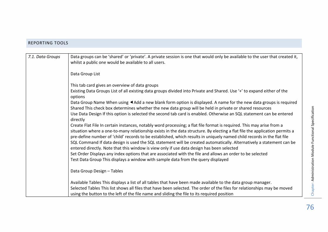
Ch
apte
r: A
dm
inis
trat
ion
Mo
du
le F
un
ctio
nal
Sp
ecif
icat
ion
76
REPORTING TOOLS
7.1. Data Groups Data groups can be ‘shared’ or ‘private’. A private session is one that would only be available to the user that created it, whilst a public one would be available to all users. Data Group List This tab card gives an overview of data groups Existing Data Groups List of all existing data groups divided into Private and Shared. Use ‘+’ to expand either of the options Data Group Name When using Add a new blank form option is displayed. A name for the new data groups is required Shared This check box determines whether the new data group will be held in private or shared resources Use Data Design If this option is selected the second tab card is enabled. Otherwise an SQL statement can be entered directly Create Flat File In certain instances, notably word processing; a flat file format is required. This may arise from a situation where a one-to-many relationship exists in the data structure. By electing a flat file the application permits a pre-define number of ‘child’ records to be established, which results in uniquely named child records in the flat file SQL Command If data design is used the SQL statement will be created automatically. Alternatively a statement can be entered directly. Note that this window is view only if use data design has been selected Set Order Displays any index options that are associated with the file and allows an order to be selected Test Data Group This displays a window with sample data from the query displayed Data Group Design – Tables Available Tables This displays a list of all tables that have been made available to the data group manager. Selected Tables This list shows all files that have been selected. The order of the files for relationships may be moved using the button to the left of the file name and sliding the file to its required position
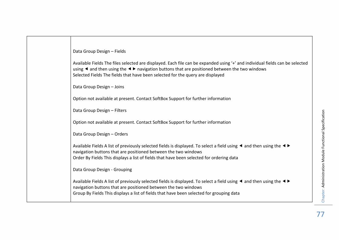
Ch
apte
r: A
dm
inis
trat
ion
Mo
du
le F
un
ctio
nal
Sp
ecif
icat
ion
77
Data Group Design – Fields Available Fields The files selected are displayed. Each file can be expanded using ‘+’ and individual fields can be selected using and then using the navigation buttons that are positioned between the two windows Selected Fields The fields that have been selected for the query are displayed Data Group Design – Joins Option not available at present. Contact SoftBox Support for further information Data Group Design – Filters Option not available at present. Contact SoftBox Support for further information Data Group Design – Orders Available Fields A list of previously selected fields is displayed. To select a field using and then using the navigation buttons that are positioned between the two windows Order By Fields This displays a list of fields that have been selected for ordering data Data Group Design - Grouping Available Fields A list of previously selected fields is displayed. To select a field using and then using the navigation buttons that are positioned between the two windows Group By Fields This displays a list of fields that have been selected for grouping data
Ch
apte
r: A
dm
inis
trat
ion
Mo
du
le F
un
ctio
nal
Sp
ecif
icat
ion
78
Flat File Options This tab card is used to convert one-to-many data sets into a flat file. Data Group Fields This is a list of all fields that have been set up in the query Normalised The check box is used to select a field that needs to be converted to flat format. Once this check box has been selected a maximum limit can be set Group If the fields are required to be grouped then using this check box add the field to the Grouping Field Order window Normalised Field (Max) This sets the upper limit for the number of flat records to be created from a one-to-many relationship
7.2. Quick Query The purpose behind ‘Quick Query’ is to enable a user to be able to easily extract some data from a table in the application and to transfer that data to an environment in which they wish to create some output e.g. Excel spreadsheet. It is not designed as a comprehensive report-writing tool. For this purpose a product Crystal Reports is recommended. Many of the reports used in the application are written using Crystal Reports, which for the standard reports is supplied with a royalty free runtime module. Select File is a drop down data item. It displays a list of all the files in the application. Once a file has been selected the data items in that file will be displayed in the window below. Please note that only one file may be selected for this quick query tool. If as a user, you have an understanding of SQL language, then it is possible to construct the Query command manually, in order to gain more complex result Fields is a list of all the data items that appear in the selected table or file Select All is a button which when used results in all the data items under fields being ticked Select None removes the ticks from the data items and allows the user to choose selected fields. Note that as these options are used the Query Command changes to reflect the query requirements
Ch
apte
r: A
dm
inis
trat
ion
Mo
du
le F
un
ctio
nal
Sp
ecif
icat
ion
79
Query Command is the SQL syntax that is generated by the instructions given by the user. It can also be used to enter a direct query in SQL for experienced SQL users Run Query is used to generate Query Results. This will display the data that has been requested. Once a result set has been displayed it is possible to further modify the data using the following commands Set Filter selects only the data that meets a specific requirement. To select a filter condition highlight a single data item in one of the columns of data displayed in the Query Results. Note that the selected column title changes to red text to indicate the active column. Use Set Filter respond Yes to the Requery question. The data displayed now reflects the selected data item only, and the text displayed in Query Command has also changed. The Set Filter button text has now changed to Reset Filter to allow the filter command to be undone if not required Set Order works in a similar way to Set Filter. By using the mouse to select a column and using Set Order the data is re-organised into ascending order. Note that an additional option has become enabled which allows the data order to be reversed into descending order if required. Once an Order has been set, the button text changes to Reset Order to allow the action to be cancelled Export button displays the following form It is used to transfer the data to another format e.g. Excel. First choose the file type required. If a delimited text file is selected the option delimiter becomes available Delimiter is only used with delimited text files and allows the user to define the field separator (normally ‘,’) for use by other applications. An option is also included that allows field names to be included as the first line in the output file Export To Path/Filename allows the user to define the filename and where it should be stored once it has been created. If the location needs to be found use the ellipsis button at the end of the field to display a location finder Export button creates the file type requested in the specified location OK returns to the previous screen Save Query displays a form on which the details of the query are stored. This also enables the query to be named for
Ch
apte
r: A
dm
inis
trat
ion
Mo
du
le F
un
ctio
nal
Sp
ecif
icat
ion
80
later retrieval New Query clears the current form if any details are displayed and allows the user to begin the process of defining a new ‘quick query’ Open Query displays a list of previously saved ‘quick queries’. By opening the query the details are displayed. To display the data use Run Query