Embed Size (px)
Citation preview

Us
er
’s M
an
ua
lSL-15U
Adjustable Speed Controlfor Bodine Shunt Wound
1/70 and 1/50 HP115 VDC Motors

Copyright 2001 byMinarik Corporation
All rights reserved. No part of this manual may be reproduced or transmitted in any formwithout written permission from Minarik Corporation. The information and technical datain this manual are subject to change without notice. Minarik Corporation and itsDivisions make no warranty of any kind with respect to this material, including, but notlimited to, the implied warranties of its merchantability and fitness for a given purpose.Minarik Corporation and its Divisions assume no responsibility for any errors that mayappear in this manual and make no commitment to update or to keep current theinformation in this manual.
Printed in the United States of America.

� Safety Warnings
Note: This symbol � denotes an important safety message. Please readthese sections carefully before performing any instructions contained in thismanual.
• Have a qualified electrical maintenance technician install,adjust and service this equipment. Follow the NationalElectrical Code and all other applicable electrical and safetycodes, including the provisions of the Occupational Safetyand Health Act (OSHA), when installing equipment.
• Reduce the chance of an electrical fire, shock, or explosionby proper grounding, over current protection, thermalprotection, and enclosure. Follow sound maintenanceprocedures.
i

ii
Table of ContentsGeneral Information . . . . . . . . . . . . . . . . . . . . . . . . . . . . . . . . . . . . . . . . . . . . . . . . .1Features . . . . . . . . . . . . . . . . . . . . . . . . . . . . . . . . . . . . . . . . . . . . . . . . . . . . . . . . .2Specifications . . . . . . . . . . . . . . . . . . . . . . . . . . . . . . . . . . . . . . . . . . . . . . . . . . . . .3Dimensional Data . . . . . . . . . . . . . . . . . . . . . . . . . . . . . . . . . . . . . . . . . . . . . . . . . .4Installation . . . . . . . . . . . . . . . . . . . . . . . . . . . . . . . . . . . . . . . . . . . . . . . . . . . . . . . .6
Alternative Wiring . . . . . . . . . . . . . . . . . . . . . . . . . . . . . . . . . . . . . . . . . . . . . . . . . . . . .8Calibration . . . . . . . . . . . . . . . . . . . . . . . . . . . . . . . . . . . . . . . . . . . . . . . . . . . . . . . .9
Maximum Speed and Regulation (IR COMP) Adjustment . . . . . . . . . . . . . . . . . . . . . . .9Standard Calibration . . . . . . . . . . . . . . . . . . . . . . . . . . . . . . . . . . . . . . . . . . . . . . . . .11
Application Notes . . . . . . . . . . . . . . . . . . . . . . . . . . . . . . . . . . . . . . . . . . . . . . . . .14Speed Adjustment . . . . . . . . . . . . . . . . . . . . . . . . . . . . . . . . . . . . . . . . . . . . . . . . . . .15Adjustable / Maximum Speed . . . . . . . . . . . . . . . . . . . . . . . . . . . . . . . . . . . . . . . . . . .16Multiple Fixed Speeds . . . . . . . . . . . . . . . . . . . . . . . . . . . . . . . . . . . . . . . . . . . . . . . . .17Adjustable Speeds in Two or More Non-Overlapping Speed Ranges . . . . . . . . . . . . . .18Multiple Full Range Adjustable Speeds . . . . . . . . . . . . . . . . . . . . . . . . . . . . . . . . . . . .19External Signal Control . . . . . . . . . . . . . . . . . . . . . . . . . . . . . . . . . . . . . . . . . . . . . . . .19High Speed Range . . . . . . . . . . . . . . . . . . . . . . . . . . . . . . . . . . . . . . . . . . . . . . . . . . .21
Run / Stop Circuits . . . . . . . . . . . . . . . . . . . . . . . . . . . . . . . . . . . . . . . . . . . . . . . .22Run / Stop Using Normally Closed Contacts . . . . . . . . . . . . . . . . . . . . . . . . . . . . . . . .22Run / Stop Using Normally Open Contacts . . . . . . . . . . . . . . . . . . . . . . . . . . . . . . . . .23

iiiTable of Contents
Reversing Circuits . . . . . . . . . . . . . . . . . . . . . . . . . . . . . . . . . . . . . . . . . . . . . . . . .24Reversing with a Toggle Switch . . . . . . . . . . . . . . . . . . . . . . . . . . . . . . . . . . . . . . . . . .25Reversing with Relays . . . . . . . . . . . . . . . . . . . . . . . . . . . . . . . . . . . . . . . . . . . . . . . .26DC Shunt Wound Motor Dynamic Braking Theory . . . . . . . . . . . . . . . . . . . . . . . . . . . .27Gearmotor Caution . . . . . . . . . . . . . . . . . . . . . . . . . . . . . . . . . . . . . . . . . . . . . . . . . . .29
Dynamic Braking Circuit Cautions . . . . . . . . . . . . . . . . . . . . . . . . . . . . . . . . . . . . .29Run/Stop with Dyanmic Braking using a Toggle Switch . . . . . . . . . . . . . . . . . . . . . . . .30Run/Stop Dynamic Braking using a Relay . . . . . . . . . . . . . . . . . . . . . . . . . . . . . . . . . .31
Reversing with Dynamic Braking Circuits . . . . . . . . . . . . . . . . . . . . . . . . . . . . . . . .33Reversing with Dynamic Braking using a Rotary Switch . . . . . . . . . . . . . . . . . . . . . . .33Reversing with Dynamic Braking using Relays . . . . . . . . . . . . . . . . . . . . . . . . . . . . . .35
Limit Switch Circuits . . . . . . . . . . . . . . . . . . . . . . . . . . . . . . . . . . . . . . . . . . . . . . .37Toggle Switch Reversing with Limit Switches . . . . . . . . . . . . . . . . . . . . . . . . . . . . . . . .38Relay Reversing with Dynamic Braking and Limit Switches . . . . . . . . . . . . . . . . . . . . .40
Troubleshooting . . . . . . . . . . . . . . . . . . . . . . . . . . . . . . . . . . . . . . . . . . . . . . . . . . .42Parts List . . . . . . . . . . . . . . . . . . . . . . . . . . . . . . . . . . . . . . . . . . . . . . . . . . . . . . . .46Unconditional Warranty . . . . . . . . . . . . . . . . . . . . . . . . . . . . . . . . .inside back cover

iv
IllustrationsFigure 1. Maximum Speed & Regulation Trimpot Locations . . . . . . . . . . . . . . . . . . . . . . . . . . . . .4
Figure 2. SL15U Connections . . . . . . . . . . . . . . . . . . . . . . . . . . . . . . . . . . . . . . . . . . . . . . . . . . .5
Figure 3. Maximum Speed and Regulation Trimpot Locations . . . . . . . . . . . . . . . . . . . . . . . . . . .13
Figure 4. Adjustable / Fixed Speeds . . . . . . . . . . . . . . . . . . . . . . . . . . . . . . . . . . . . . . . . . . . . . .16
Figure 5. Multiple Fixed Speeds . . . . . . . . . . . . . . . . . . . . . . . . . . . . . . . . . . . . . . . . . . . . . . . . .17
Figure 6. Two Non-Overlapping Speed Ranges . . . . . . . . . . . . . . . . . . . . . . . . . . . . . . . . . . . . .18
Figure 7. Two Full Range Adjustable Speeds . . . . . . . . . . . . . . . . . . . . . . . . . . . . . . . . . . . . . . .20
Figure 8. External Signal Control . . . . . . . . . . . . . . . . . . . . . . . . . . . . . . . . . . . . . . . . . . . . . . . .20
Figure 9. Field Weakening Resistor for High Speed Range . . . . . . . . . . . . . . . . . . . . . . . . . . . . .21
Figure 10. Run / Stop Using Normally Closed Contacts . . . . . . . . . . . . . . . . . . . . . . . . . . . . . . .22
Figure 11. Run / Stop Using Normally Open Contacts . . . . . . . . . . . . . . . . . . . . . . . . . . . . . . . . .23
Figure 12. Reversing with Toggle Switch . . . . . . . . . . . . . . . . . . . . . . . . . . . . . . . . . . . . . . . . . .25
Figure 13. Reversing with Relays . . . . . . . . . . . . . . . . . . . . . . . . . . . . . . . . . . . . . . . . . . . . . . . .26
Figure 14. Run / Stop Dynamic Braking with Toggle Switch . . . . . . . . . . . . . . . . . . . . . . . . . . . .30
Figure 15. Run / Stop Dynamic Braking using a Relay . . . . . . . . . . . . . . . . . . . . . . . . . . . . . . . .32
Figure 16. Rotary Switch Reversing with Dynamic Braking . . . . . . . . . . . . . . . . . . . . . . . . . . . . .34
Figure 17. Reversing with Dynamic Braking using Relays . . . . . . . . . . . . . . . . . . . . . . . . . . . . . .36
Figure 18. Toggle Switch Reversing with Limit Switches . . . . . . . . . . . . . . . . . . . . . . . . . . . . . . .39
Figure 19. Relay Reversing / Braking with Limit Switches . . . . . . . . . . . . . . . . . . . . . . . . . . . . . .41

The Model SL15U Minarik adjustable speed control is a full wave,solid state device that is designed to control and vary the speed ofBodine 1/70th and 1/50th HP, 115 VDC shunt wound motors. Thecontrol has choke/capacitor filtering to assure the controlled motorwill be extra quiet, smooth and cool running. In a typical application2% base speed regulation is provided with the help of temperature,line voltage, and IR compensation. The control features a speedrange of 25:1, adjustable IR compensation, and a maximum speedadjustment to limit high speed operation. The Model SL15U Minarikadjustable speed control is a U.L. (Underwriters Laboratories)recognized component, File E35603.
1
General Information

2
Features
• Choke/Capacitor Filtering
• Temperature Compensation
• 2% Base Speed Regulation (Typical Application)
• Maximum Speed Adjustment
• Adjustable IR Compensation
• Line Starting and Stopping
• Line Voltage Compensation
• Full Wave Armature and Field Supply

3
Input Voltage 115 VAC, 50/60 Hz Single Phase
Maximum Input current 0.9 Ampheres
Output Armature Voltage 0 - 115 VDC
Output Armature Current 0.25 Amperes
Output Field Voltage 100 VDC
Output Field Current 0.2 Amperes
Weight 8.0 Ounces
Ambient Temperature Range 10° thru 40° Centigrade
Specifications

4
Dimensional Data
SO1
2.625[67]
3.000[76.2]
0.1875 [5]4.125 [105]
4.500 [114]
REG
P3
MAX SPD
P2
Figure 1. Maximum Speed & Regulation Trimpot Locations
ALL DIMENSIONS IN INCHES [MILLIMETERS]

5
P16K SPEED ADJUSTPOTENTIOMETER
CW
GRAY
BROWN
VIOLET
SO1
PL1
ARMATUREFIELD
115 VAC50/60 HZ
FUSE WITH1.5 AMP QUICKACTING FUSE
BLK/WHT
WHITE
(neutral)
(hot)
++ - -
BLU
E
YE
LLO
W
RE
D
1/50 HP OR LESS 115 VDC SHUNT WOUND MOTOR
Figure 2. SL15U Connections

6
The SL15U is an uncased chassis model and is designed to beinstalled in original equipment. The speed adjust pot (P1) and itsmounting hardware is supplied with the control. Mount the speedadjust pot through a 3/8” hole with the insulator disc between the potand the inside of the panel. The lock washer is placed between theoutside of the panel and the lock nut. Mount the chassis toappropriate subplates using the four threaded (6-32) mountingstand-offs (refer to Figure 1 on page 4 for mounting dimensions).The chassis has adequate heat sinking to properly dissipate theload generated heat and can be either vertically or horizontallymounted.
Installation

7Installation
Leave enough room around the outer dimensions of the chassis toallow access to the chassis after installation for unmounting,installing wiring, calibration and other related reasons. Connectionsare to be made to the cable wiring shown in Figure 2 on page 5.WARNING: The SL15U is not isolated from earth ground. Unlessan isolation transformer is used, circuit components are at apotential of 115 volts above ground. Please refer to SafetyPrecautions on page i before installing.
1. Connect the speed adjust pot to its appropriate wires. These 3wires should NOT be bundled with the motor and power lineleads because induced voltages could cause erratic operation.If the speed adjust pot requires wiring longer than 18”, a shieldedcable must be used and one end ONLY of the shielding must beconnected to earth ground.

8 Installation
2. Connect the motor to its appropriate wires. If the motor rotatesin the wrong direction, reverse the motor armature leads. DoNOT plug reverse the motor.
3. Connect the power line to the appropriate wires. The hot leg ofthe power line should be fused with a fast blow 1.5 amp fuse toprotect the control. The motor may be started and stopped withthe power line at any speed setting on the speed adjust pot. Themotor coasts to a stop when the power line is disconnected. Ifdynamic braking is desired see Application Notes section.
Alternative Wiring
By utilizing additional components the SL15U may be operated byexternal signal control, have multiple preset speeds, dynamicbraking, limit switch operation, etc. Please refer to ApplicationNotes section for these and other modes of operation.

9
Maximum Speed and Regulation (IR COMP) Adjustment
IMPORTANT: A non-metallic screwdriver should be used whenadjusting the trim pots to avoid any possibility of the screwdriver’sblad contacting live circuitry and shorting the circuitry or allowingcontact with any dangerous or fatal voltages.
Dangerous voltages exist on the printed circuit board. Contact withcomponents and/or printed circuitry could cause serious injury orfatality. Please refer to the Safety Warnings on page i.
�Warning
Two potentiometers, located on the control PC board, are providedfor adjustment of the maximum motor speed and regulation of themotor’s speed.
Calibration

10 Calibration
MAXIMUM SPEED ADJUSTMENT
This feature is provided to allow the motor speed to be adjustedbetween 75 to 120% of motor name plate rated speed when thespeed adjust knob is set at maximum.
REGULATION (IR COMPENSATION)
Regulation is obtained by circuitry which raises the armaturevoltage to maintain speed when increased loading tends to slow themotor down.
11
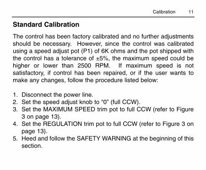
The control has been factory calibrated and no further adjustmentsshould be necessary. However, since the control was calibratedusing a speed adjust pot (P1) of 6K ohms and the pot shipped withthe control has a tolerance of ±5%, the maximum speed could behigher or lower than 2500 RPM. If maximum speed is notsatisfactory, if control has been repaired, or if the user wants tomake any changes, follow the procedure listed below:
1. Disconnect the power line.2. Set the speed adjust knob to “0” (full CCW).3. Set the MAXIMUM SPEED trim pot to full CCW (refer to Figure
3 on page 13).4. Set the REGULATION trim pot to full CCW (refer to Figure 3 on
page 13).5. Heed and follow the SAFETY WARNING at the beginning of this
section.
Standard Calibration
Calibration
12 Calibration
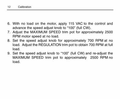
6. With no load on the motor, apply 115 VAC to the control andadvance the speed adjust knob to “100” (full CW).
7. Adjust the MAXIMUM SPEED trim pot for approximately 2500RPM motor speed at no load.
8. Set the speed adjust knob for approximately 700 RPM at noload. Adjust the REGULATION trim pot to obtain 700 RPM at fullload.
9. Set the speed adjust knob to “100” (full CW) and re-adjust theMAXIMUM SPEED trim pot to approximately 2500 RPM noload.

13
Figure 3. Maximum Speed and Regulation Trimpot Locations
MAXIMUM SPEED
REGULATION (IR COMP)
Calibration

14
DISCLAIMER - The following circuitry does not purport to cover allpossible details or variations, nor to provide for every possiblecontingency to be met with connection, installation, operation, ormaintenance - and no warranty of fitness for purpose is expressedor implied. And further, Minarik Corporation assumes noresponsibility for the use of any circuitry described and makes norepresentation that they are free from patent infringement.
Application Notes
The components shown in the following circuitry should only beconnected by qualified electrical personnel familiar with theconstruction, operation, and hazards of all the components used.Personal injury and/or equipment damage may occur if componentsare improperly connected, installed, adjusted, or serviced. Also referto the Safety Warnings on page i.
Warning�

15Application Notes
The speed adjust potentiometer (P1), supplied with the control, isonly one of many methods which can be used to control the motorspeed. With any alternative methods, these precautions must befollowed for proper control operation:
a. A 6K (6,000) Ohm (± 5%) total resistance path must bemaintained between the gray and violet leads.
b. Any replacement resistors or potentiometers must becapable of carrying 10 milliamperes.
c. The three speed adjust circuit leads (brown, gray, and violet)should NOT be bundled with the motor and power lineleads.
d. If the length of the three speed adjust circuit leads exceeds18” then a shielded cable must be used and ONLY one endof the shielding must be connected to an earth ground.
Speed Adjustment

16 Application Notes
The addition of a single pole, double-throw switch or relay contactallows a selection of a continuously variable or a fixed maximumspeed (see Figure 4 below). This is useful in applications where afast return to the “home” position is desired after certain operationshave been accomplished at slower adjustable speeds.
Adjustable / Maximum Speed
6K OHMSPEED ADJUST
POTENTIOMETER (P1)
BROWN
GRAY
VIOLETCW
PL1
Figure 4. Adjustable / Fixed Speeds

17
This is accomplished by using a multi-position switch with thecorrect number of positions for the desired number of fixed speedsand the same number of resistors with a total series resistance of6K Ohms to replace speed adjust pot (P1). See Figure 5 below.
Multiple Fixed Speeds
BROWN
GRAY
VIOLET
Total SeriesResistance
6K Ohm
R1
R4
R2
R3
PL1
Figure 5. Multiple Fixed Speeds
Application Notes

18 Application Notes
This is accomplished by replacing the speed adjust pot (P1) withtwo or more potentiometers connected in series (total seriesresistance must be 6K Ohms) and a multi-position switch.Illustrated is a connection diagram for two speed control with highand low speed adjust pots. See Figure 6 below.
Adjustable Speeds in Two or More Non-OverlappingSpeed Ranges
BROWN
GRAY
VIOLET
PL1
CW
CW
3K OHM
3K OHM
LOWSPEED
HIGHSPEED
Figure 6.Two Non-
OverlappingSpeed Ranges

19
Using an ungrounded floating signal of 0 through 10 VDC willoperate the control’s motor thru a speed range of 0 thru 1800 RPM.This is accomplished by inserting a 1K Ohm fixed resistor in serieswith the speed adjust pot (P1) wiper contact and applying the DCvoltage across the resistor. P1 is used to set the minimum voltagerequired to start the motor running. If only a grounded signal isavailable, it can be converted to an ungrounded floating signal witha Minarik PCM4 Process Control Module. See Figure 8, page 20.
External Signal Control
This is accomplished by replacing the speed adjust pot (P1) withtwo or more potentiometers connected in parallel (total parallelresistance must be 6K Ohms) and a multi-position switch.Illustrated is a connection diagram for two full range adjustablespeeds. See Figure 7, page 20.
Multiple Full Range Adjustable Speeds
Application Notes

20 Application Notes
BROWN
GRAY
VIOLETCW
PL1
1K OHM
+ -
To UngroundedDC Floating Signal
6K OHMSPEED ADJUST
POTENTIOMETER (P1)
BROWN
GRAY
VIOLET
PL1
CW CW
EACH POT12K OHM
Figure 8.External
Signal Control
Figure 7. TwoFull RangeAdjustable
Speeds

21Application Notes
This is accomplished by connecting a 1K Ohm, 5 Watt resistor inseries with the motor field winding and the SL15U field powersupply, which lowers the voltage to the motor field winding. Thislowering of the motor field voltage weakens the motor field andallows the motor top speed to increase to 3150 RPM. See Figure 9below.
High Speed Range
BLUE
YELLOW
RED
PL1
1K OHM
5W
FIELD
ARMATURE
Figure 9. FieldWeakening Resistor for
High Speed Range

22 Application Notes
This is accomplished by inserting a set of normally closed contactsin series with the violet wire that connects to the speed adjust pot.When the contacts are opened, the motor will coast to a stop. Thismethod is desirablewhen dynamic brakingis not needed withapplications wherefrequent starts andstops are required andhas the advantage ofnot having to switchthe AC power line orthe DC armature line.See Figure 10.
Run / Stop Using Normally Closed Contacts
BROWN
GRAY
VIOLET
P1
CW
PL1
STOP
RUN
Figure 10. Run / Stop Using NormallyClosed Contacts
Run / Stop Circuits

23
This is accomplished by inserting a set of normally open contacts inparallel with the gray and brown wires that connect to the speedadjust pot. When the contacts are closed, the motor will coast to astop. This method is desirable when dynamic braking is not neededwith applications where frequent starts and stops are required and
has the advantage ofnot having to switch theAC power line or theDC armature line. SeeFigure 11.
Run / Stop Using Normally Open Contacts
Figure 11. Run / Stop Using NormallyOpen Contacts
BROWN
GRAY
VIOLET
P1
CW
PL1
STOP
RUN
Application Notes

24
To reverse a DC shunt wound motor, the polarity of the armaturewinding must be transposed with the polarity of the field winding.The normal procedure is to leave the field winding energized and todisconnect and reconnect the armature circuit. IMPORTANT: Plugreversing the motor (not allowing the motor to come to a stop beforereversing) will cause excessively high currents to flow in thearmature circuit, which can damage the control and/or motor and isnot recommended. If rapid reversing is required, use one of thedyanmic braking circuits listed in this manual.
Reversing Circuits

25Reversing Circuits
This can be accomplished by using a DPDT, center off toggleswitch. When power is applied to the control and the toggle switchis in the center position, the motor is stopped. When the toggleswitch is actuated in one direction, the motor will run forward. Whenthe toggle switch is moved back to the center position, the motorcoasts to a stop.When the toggleswitch is actuated inthe other direction,the motor will run inreverse. See Figure12.
Reversing with a Toggle Switch
BLUE
YELLOW
RED
FIELD
ARMATURE
FWDREV
Figure 12. Reversingwith Toggle Switch

26 Reversing Circuits
This is accomplished with two 3PDT relays and three momentary operatedpushbutton switches (two with normally open contacts and one with normallyclosed contacts). L1 and L2 supplypower to the relay holding circuitry.Normally, if the Forward, Stop, andReverse pushbuttons are to belocated remotely from the control,low voltage relay coils are used. Inoperation, power is applied to theSL15U control and the appropriatevoltage to L1 and L2. When PB1 isactuated, the motor will runFORWARD. When PB2 is actuated,the motor will STOP. When PB3 isactuated, the motor will run inREVERSE. When the motor isrunning, a change in direction is notpossible without actuating PB2(STOP) first. See Figure 13.
Reversing with Relays
BLUE
YELLOW
RED
FIELD
ARMATURE
PL1
FR
RR
FR
RR
FR
RR FR
RR
RR
FR
REV
FWD
REVRELAY
FWDRELAY
Figure 13. Reversing with Relays

27
In operation, a shunt wound field DC motor has the field andarmature connected in parallel across their respective DC powersupplies. The interaction of the magnetic field created by the fieldwinding and the current flowing in the armature winding cuases themotor to run. A voltage called the counter electromotive force(CEMF) is generated in the armature conductors, when rotated in amagnetic field. When the motor is running, the CEMF opposes thepower supply voltage and limits the armature current to a sufficientvalue to supply adequate output shaft torque. Braking isaccomplished by disconnecting the armature from the DC power(while leaving the field connected) and shorting the armature leadswith a current limiting resistor. As soon as this is done, the armatureand its driven load will begin to stop. Since the armature is stillrotating in a magnetic field, it will continue to generate a CEMFwhich is proportional to the strength of the magnetic field and willcause a current flow opposite to that of the power supply to flow inthe current limiting (braking) resistor, which will in turn cause the
DC Shunt Wound Motor Dynamic Braking Theory
Reversing Circuits

28
motor to try and reverse itself. In the process of trying to reverseitself, the speed will be rapidly reduced from the original directionand as the speed decreases, so does the CEMF. When the motorreaches zero speed, the CEMF is also zero and the motor has beendynamically braked to a stop. The speed of braking is controlled bythe braking (current limiting) resistor’s resistance. The lower theresistance, the greater the current flow. And, since the reversingcurrent or braking torque is proportional to the current flow, thefaster the stopping. For the SL15U a jumper wire instead of aresistor gives optimum braking.
Reversing Circuits

29
Care must be taken when using dynamic braking with gearmotorsconnected to inertial type loads. Forces can be developed whichmay be destructive to the gearing. IMPORTANT: Dynamic brakingis only for fast stopping and NOT for holding a load.
Dynamic Braking Circuit CautionsGearmotor Caution

30 Dynamic Braking Circuit Cautions
This can be accomplished with a SPDT toggle switch and a jumperwire in place of a dynamic braking resistor. Power is applied to thecontrol. When the toggle switch is switched to RUN position, themotor starts running. When the toggle switch is switched to BRAKEposition, the motor is dynamically braked to a stop. See Figure 14.
Run/Stop with Dyanmic Braking using a Toggle Switch
BLUE
YELLOW
REDFIELD
ARMATURE
PL1
BRAKE
RUNJUMPER WIRE
Figure 14. Run / Stop Dynamic Braking with Toggle Switch

31
This can be accomplished with a DPDT relay, two momentaryoperated pushbutton switches (one normally open and one normallyclosed) and a jumper wire in place of a dynamic braking resistor.Normally, if the Run and Brake pushbuttons are to be locatedremotely from the control, a low voltage relay coil is used. Inoperation, power is applied to the SL15U control and theappropriate voltage to L1 and L2. When PB1 is actuated, the motorwill run and when PB2 is actuated, the motor will dynamically braketo a stop. See Figure 15, page 32.
Run/Stop Dynamic Braking using a Relay
Dynamic Braking Circuit Cautions

32
BLUE
YELLOW
RED
FIELD
ARMATURE
PL1FR
STOP
L1
RUN
RUN
RUN
L2 JUMPERWIRE
Figure 15. Run / Stop Dynamic Braking using a Relay
Dynamic Braking Circuit Cautions

33
This can be accomplished with a 2-pole, 3-position rotary switchand a jumper wire in place of a dynamic braking resistor. Whenpower is applied to the control and the rotary switch is switched toFORWARD, the motor starts running in one direction. When therotary switch is switched to BRAKE, the motor is dynamically brakedto a stop. When the rotary switch is switched to REVERSE, themotor starts running in the opposite direction. See Figure 16, page34.
Reversing with Dynamic Braking using a Rotary Switch
Reversing with Dynamic Braking Circuits

34
BLUE
YELLOW
RED
ARMATURE
PL1
FIELD
1
2
3
JUMPERWIRE
1 FWD2 BRAKE3 REV
Figure 16. Rotary Switch Reversing with Dynamic Braking
Reversing with Dynamic Braking Circuits

35
This can be accomplished with two 3PDT relays, three momentaryoperated pushbutton switches (two with normally open contacts andone with normally closed contacts) and a jumper wire in place of adynamic braking resistor. L1 and L2 supply power to the relayholding circuitry. Normally, if the Forward, Brake, and Reversepushbuttons are to be located remotely from the control, low voltagerelay coils are used. In operation, power is applied to the SL15Ucontrol and the appropriate voltage to L1 and L2. When PB1 isactuated, the motor will dynamically BRAKE to a stop. When PB3is actuated, the motor will run in REVERSE. When the motor isrunning, a change in direction is not possible without actuating PB2(BRAKE) first. See Figure 17, page 36.
Reversing with Dynamic Braking using Relays
Reversing with Dynamic Braking Circuits

36
BLUE
YELLOW
RED
FIELD
ARMATURE
PL1
FR
RR
FR
RR FR
RR
RR
FR
REV
FWD
REVRELAY
FWDRELAY
FR
JUMPERWIRE
L1 L2
RR
FR
Figure 17. Reversing with Dynamic Braking using Relays
Reversing with Dynamic Braking Circuits

37
Be sure to use some type of override device on the limit switchactuators so that motor coast does not damage limit switches orallow limit switches to deactivate.
DYNAMIC BRAKING CIRCUIT CAUTIONS - Care must be takenwhen using dynamic braking with gearmotors connected to inertialtype loads. Forces can be developed which may be destructive tothe gearing.
IMPORTANT - Dynamic braking is only for fast stopping and NOTfor holding a load.
Limit Switch Circuits

38 Limit Switch Circuits
This can be accomplished with a 3PDT, center off toggle switch andtwo normally closed limit switches. When power is applied to thecontrol and the toggle switch is in the center position, the motor isSTOPPED. When the toggle switch is actuated in one direction, themotor runs FORWARD until the limit switch is actuated and themotor stops. When the toggle switch is actuated in the otherdirection, the motor will run in REVERSE until the limit switch isactuated and the motor stops. See Figure 18, page 39.
Toggle Switch Reversing with Limit Switches

39
BLUE
YELLOW
REDFIELD
ARMATURE
PL1
LS1 LS2
FWDREV
Figure 18. Toggle Switch Reversing with Limit Switches
Limit Switch Circuits

40 Limit Switch Circuits
This can be accomplished with two 3PDT relays, three momentaryoperated pushbutton switches (two with normally open contacts andone with normally closed contacts), two normally closed limitswitches and a jumper wire in place of a dynamic braking resistor.L1 and L2 supply power to the relay holding circuitry. Normally, ifthe Forward, Brake, and Reverse pushbuttons are to be locatedremotely from the control, low voltage relay coils are used. Inoperation, power is applied to the SL15U control and theappropriate voltage to L1 and L2. When PB1 is actuated, the motorwill run FORWARD until the limit switch is actuated and the motordynamically brakes to a stop. When PB3 is actuated, the motor willrun in REVERSE until the other limit switch is actuated and themotor dynamically brakes to a STOP. When PB2 is actuated, themotor will dynamically BRAKE to a STOP. When the motor isrunning, a change in direction is not possible without actuating PB2(BRAKE) first. If dynamic braking is not desired eliminate thejumper wire. See Figure 19, page 41.
Relay Reversing with Dynamic Braking and Limit Switches

41
BLUE
YELLOW
RED
FIELD
ARMATURE
PL1
FR
RR
FR
RR
FR
RR FR
RR
RR
FR
REV
FWD
REVRELAY
FWDRELAY
FR
JUMPERWIRE
L1 L2
LS1
LS2
RR
Figure 19. Relay Reversing / Braking with Limit Switches
Limit Switch Circuits

42
Before proceeding check the following:
1. Be sure the power line is the same voltage as that listed on thecontrol nameplate.
2. Check to see that the line fuse is of the same value as shown onthe control nameplate.
Troubleshooting

43Troubleshooting
I. Heed and follow the SAFETY WARNING at the beginning of theCalibration section (page 8).
II. Set speed control pot, P1, at zero on the dial and apply power.If the line fuse blows, disconnect the power and check thefollowing:
A. Transient suppressor, DAS, may be shorted.B. One or more of the diodes (D2, D3, D4, or D5) may be
shorted.1. Disconnect the motor from the control.2. Across each of the diodes, resistance should read high
in one direction and low in the opposite direction.C. Motor cable or motor field may be shorted or grounded. A
resistance reading on the motor cable field connectionsshould read approximately 1190 ohms.

44 Troubleshooting
III. Connect the motor to the control, apply power, and advance thespeed adjust knob to the maximum setting on the dial:
A. If the line fuse continues to blow:1. The motor may be overloaded.
a. Disconnect the power from the control.b. Disconnect the load from the motor.c. Apply power. Motor should run at full speed
without blowing the fuse.2. Motor armature or motor cable may be shorted or
grounded. Disconnect the motor cable. An ohmmeterreading on the motor cable armature connectionsshould read approximately 118 ohms. A reading fromeither side of the armature connections to the motorframe should show open (use high ohm scale).
3. Motor field circuit may be open. An ohmmeter readingbetween the motor cable field connections should readapproximately 1190 ohms.

45
4. The filter capacitor (C4), may be shorted.5. A diode (D2, D3, D4, or D5) may be open causing the
fuse to blow at no load or very light load. This may bedue to high armature current, or a weak field.
6. Diode (D1) may be shorted.
B. If the fuse does not blow, but the motor will not run:1. The speed control potentiometer (P1) may be open.2. The rectifier (SCR), may be defective.3. A Transistor (Q1, Q2, or Q3) may be defective.4. The filter choke (X1), may be open.5. The zener diode (Z1), may be shorted.
IV. If the motor runs at high speed regardless of the speed controlpotentiometer setting:A. The rectifier (SCR), may be shorted.
B. A transistor (Q2 or Q3), may be shorted.
Troubleshooting

46
REFERENCE PART NUMBER DESCRIPTION
C1 010-0020 0.02 MFD 500 VOLTC2 010-0034 0.15 MFD 100 VOLTC3 011-0015 50 MFD 6 VDCC4 011-0018 50 MFD 350 VDCC5 010-0032 0.1 MFD 500 VOLTD1 071-0012 1 AMP 600 VDC SILICON DIODE
D3-D5 071-0007 3 AMP 600 VDC SILICON DIODEDAS 075-0002 TRANSIENT SUPPRESSORP1 120-0006 6K OHM 5 WATT POTP2 121-0020 20K OHM 1/4 WATT POTP3 121-0002 100 OHM 1/4 WATT POT
PL1 164-0056 11 TERMINAL CONNECTOR (FEMALE)Q1 070-0009 D5E44 OR 2N5354Q2 070-0010 2N3638 OR 2N5354Q3 070-0011 2N2923
Parts List
47
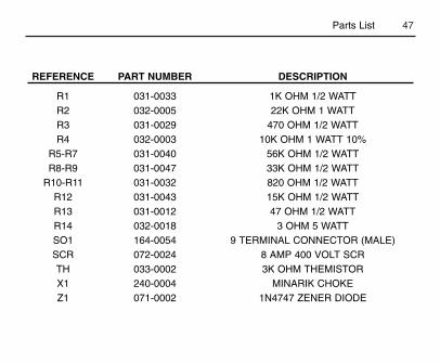
REFERENCE PART NUMBER DESCRIPTION
R1 031-0033 1K OHM 1/2 WATTR2 032-0005 22K OHM 1 WATTR3 031-0029 470 OHM 1/2 WATTR4 032-0003 10K OHM 1 WATT 10%
R5-R7 031-0040 56K OHM 1/2 WATTR8-R9 031-0047 33K OHM 1/2 WATT
R10-R11 031-0032 820 OHM 1/2 WATTR12 031-0043 15K OHM 1/2 WATTR13 031-0012 47 OHM 1/2 WATTR14 032-0018 3 OHM 5 WATTSO1 164-0054 9 TERMINAL CONNECTOR (MALE)SCR 072-0024 8 AMP 400 VOLT SCRTH 033-0002 3K OHM THEMISTORX1 240-0004 MINARIK CHOKEZ1 071-0002 1N4747 ZENER DIODE
Parts List

48
NOTES

Unconditional WarrantyA. Warranty
Minarik Corporation (referred to as "the Corporation") warrants that its products will be free from defects inworkmanship and material for twelve (12) months or 3,000 hours, whichever comes first, from date of manufacturethereof. Within this warranty period, the Corporation will repair or replace, at its sole discretion, such products thatare returned to Minarik Corporation, 901 East Thompson Avenue, Glendale, CA 91201-2011 USA.
This warranty applies only to standard catalog products, and does not apply to specials. Any returns for specialcontrols will be evaluated on a case-by-case basis. The Corporation is not responsible for removal, installation, orany other incidental expenses incurred in shipping the product to and from the repair point.
B. Disclaimer
The provisions of Paragraph A are the Corporation's sole obligation and exclude all other warranties ofmerchantability for use, express or implied. The Corporation further disclaims any responsibility whatsoever to thecustomer or to any other person for injury to the person or damage or loss of property of value caused by any productthat has been subject to misuse, negligence, or accident, or misapplied or modified by unauthorized persons orimproperly installed.
C. Limitations of Liability
In the event of any claim for breach of any of the Corporation's obligations, whether express or implied, andparticularly of any other claim or breech of warranty contained in Paragraph A, or of any other warranties, expressor implied, or claim of liability that might, despite Paragraph B, be decided against the Corporation by lawful authority,the Corporation shall under no circumstances be liable for any consequential damages, losses, or expense arisingin connection with the use of, or inability to use, the Corporation's product for any purpose whatsoever.
An adjustment made under warranty does not void the warranty, nor does it imply an extension of the original 12-month warranty period. Products serviced and/or parts replaced on a no-charge basis during the warranty periodcarry the unexpired portion of the original warranty only.
If for any reason any of the foregoing provisions shall be ineffective, the Corporation's liability for damages arisingout of its manufacture or sale of equipment, or use thereof, whether such liability is based on warranty, contract,negligence, strict liability in tort, or otherwise, shall not in any event exceed the full purchase price of such equipment.
Any action against the Corporation based upon any liability or obligation arising hereunder or under any lawapplicable to the sale of equipment or the use thereof, must be commenced within one year after the cause of suchaction arises.

901 E Thompson AvenueGlendale, CA 91201-2011
Tel: (800) MINARIK or (800) 646-2745Fax: (800) 394-6334
www.minarikcorp.comDocument Number 250-0009, Revision 6
Printed in the U.S.A – 5/01North America $10.00 Outside North America $11.00