Embed Size (px)
Citation preview

®
Electrical Products Catalog 113
APPLICATION ENGINEERINGAC & DC Controllers
ADJUSTABLE SPEED DRIVES – WHAT THEY ARE, HOW THEY WORKThe primary function of any adjustable speed drive is tocontrol the speed, torque, acceleration, deceleration anddirection of rotation of a machine. Unlike constant speedsystems, the adjustable speed drive permits the selection ofan infinite number of speeds within its operating range.Most multi-purpose production machines benefit fromadjustable speed control, since frequently their speeds mustchange to optimize the machine process or adapt it to varioustasks for improved product quality, production speed or safety.Lathes and other machine tools run small diameter workpieces at high speed and large diameter pieces at low speedsto optimize the feed rate into the cutting tool. A printing pressis operated at the speed that produces the best qualityproduct, which may vary greatly with the weight and coating ofpaper, and the characteristics of the inks used. Also, thecontrolled acceleration provided by an adjustable speed driveallows the press to accelerate smoothly to prevent breakingthe web of paper. A pump supplying water in a high risebuilding may run at very slow speeds at 3 o’clock AM tomaintain system pressure, but be called upon at 3 o’clock PMto run at high speeds to provide high flow rates necessitatedby water usage by the inhabitants.While early types of adjustable speed drives based uponmechanical and hydraulic principles still remain in limitedusage, the overwhelming choice today for industrialapplications is the electrical adjustable speed drive. No othertype offers the combined benefits of high performance, highefficiency, low maintenance, versatility and moderate initialcost. Electrical adjustable speed drives are offered in anumber of basic types, but the two most versatile for generalpurpose applications and therefore the most common, aredirect current (DC drives) and adjustable frequency (ACdrives) as manufactured by Boston Gear. Electrical adjustablespeed drives typically consist of three principle elements, asshown by the system block diagram in Figure 1.
1.OPERATOR CONTROLSTATION – THE BOSSAllows the operator to startand stop the drive controllerby push buttons or switches,and set the motor speed byturning a potentiometer to thedesired dial setting. Operatorcontrols may be integratedinto the controller or mountedremotely from the drivecontroller.2. DRIVE CONTROLLER –THE BRAINSConverts the fixed voltageand frequency of the alter nat -ing current (AC) plant powersource into an adjustablepower output to control thedrive motor over a widespeed range. The output isestablished by the speedcontrol potentiometer. Thecontroller includes sens ingcircuits to hold or regulate themotor at the desired speed with variations in the source voltageand changes in motor load. The controller also includesprotective circuitry and devices to prevent damage fromoverloads, power source transients and output power faults.3. DRIVE MOTOR – THE MUSCLETranslates electrical energyinto mechanical motion. Theoutput is a shaft rotation(RPM), which varies in pro -por tion to the power appliedby the drive controller. Themotor shaft is normallycoupled to a gear reducer or other mechanical power trans -mission device to further reduce the motor speed to a leveluseable by the driven machine.
EP23
7A
AC
POWER
DRIVECONTROLLER
OPERATORCONTROLS
DRIVEMOTOR
DRIVENMACHINE
REGULATED
POWEROUTPUT
SPEED & TORQUE
FEEDBACK
1
2 3
FIGURE 1.

®
114 Electrical Products Catalog
APPLICATION ENGINEERINGAC & DC Controllers
DC DRIVES – PRINCIPLES OF OPERATIONDC drives, because of their simplicity, ease of application,reliability and favorable cost remain the backbone of industrialapplications. A typical adjustable speed drive using a siliconcontroller rectifier (SCR) power conversion section, commonfor this type unit, is shown in Figure 2. The SCR, (also termeda thyristor) power converter converts the fixed voltagealternating current (AC) of the power source to an adjustablevoltage, controlled direct current (DC) output which is appliedto the armature of a DC motor.
FIGURE 2. TYPICAL DC DRIVESCR’s provide a controllablepower output by “phase anglecontrol”, so called because thefiring angle (a point in time wherethe SCR is triggered intoconduction) is synchronized withthe phase rotation of the AC powersource. If the device is triggeredearly in half cycle, maximumpower is delivered to the motor;late triggering in the half cycleprovides minimum power, asillustrated by Figure 3. The effectis similar to a very high speedswitch, capable of being turned onand “conducted” off at an infinitenumber of points within each halfcycle. This occurs at a rate of 60times a second on a 60 Hz line, todeliver a precise amount of powerto the motor. The efficiency of thisform of power control is extremelyhigh since a very small amount oftriggering energy can enable theSCR to control a great deal of output power.DC DRIVE TYPESNonregenerative DC Drives–Nonre gen erative DC drives arethe most conventional type in common usage. In their mostbasic form they are able to control motor speed and torque inone direction only as shown by Quadrant I in Figure 4. Theaddition of an electromechanical (magnetic) armature
reversing contactor or manual switch permits reversing thecontroller output polarity and therefore the direction of rotationof the motor armature as illustrated in Quadrant III. In bothcases torque and rotational direction are the same.Regenerative DC Drives–Regenerative adjustable speeddrives, also known as four-quadrant drives, are capable ofcontrolling not only the speed and direction of motor rotation,but also the direction of motor torque. This is illustrated byFigure 4.The term regenerative describes the ability of the drive underbraking conditions to convert the mechanical energy of themotor and connected load into electrical energy which isreturned (or regenerated) to the AC power source.When the drive is operating in Quadrants I and III, both motorrotation and torque are in the same direction and it functionsas a conventional nonregenerative unit. The uniquecharacteristics of a regenerative drive are apparent only inQuadrants II and IV. In these quadrants, the motor torqueopposes the direction of motor rotation which provides acontrolled braking or retarding force. A high performanceregenerative drive, is able to switch rapidly from motoring tobraking modes while simultaneously controlling the direction ofmotor rotation.A regenerative DC drive is essentially two coordinated DCdrives integrated within a common package. One driveoperates in Quadrants I and IV, the other operates inQuadrants II and III. Sophisticated electronic control circuitsprovide interlocking between the two opposing drive sectionsfor reliable control of the direction of motor torque and/ordirection of rotation.
EP23
3A
FIELD REGULATOR OR SUPPLY
AC
POWERSOURCE
POWER CONVERTER
FIRINGCIRCUIT
REGULATOR
OPERATOR’SCONTROL STATION
MOTORARMATURE
MOTORFIELD
DC OUTPUT
CURRENT (TORQUE)FEEDBACK
VOLTAGE (SPEED)FEEDBACK
EP11
0A
MOTOR ROTATION
TORQUE
NOTE:
QUADRANT I
QUADRANT III
QUADRANT II
QUADRANT IVARROWS
SAME DIRECTIONMOTORING (PULLING)
ARROWSOPPOSITE DIRECTIONBRAKING (HOLDING)
25% POWER
100% POWER
(–)
(+)
(–)
(+)
(–)
(+)
0 36027018090
50% POWER
Power delivered to motor
FIGURE 3. TRIGGERINGPOINTS FOR VARIOUSPOWER OUTPUTS
TABLE 1. COMPARISON OF NONREGENERATIVE VS.REGENERATIVE DC DRIVE CAPABILITIES
Braking
Reversing
Simplicity
Efficiency andSpeed Range
NonregenerativeNo inherent braking capability. Requiresthe addition of a dynamic braking circuitwhich dissipates the braking energy asheat in a resistor. Braking effort is expo -nen tial with initial high torque whichreduces to zero at zero speed. Brakingcircuits are rated for stopping only, notcontinuous hold back, or as a holdingbrake.No inherent reversing capability. Requiresthe addition of reversing contactors or aswitch to reverse the polarity of DCvoltage applied to the motor. Normallyrated for occasional reversing.The least complex and least expensiveform of electronic adjustable speed motorcontrol.
RegenerativeInherent electronically by regenerationwhereby the kinetic energy of the motorand driven machine is restored to the ACpower source. Can be regulated tocontrol the braking torque down to, andat zero speed. Typically capable ofcontinuous braking torque for hold backapplications.
An inherent capability. Motor polarity isreversed electronically with no contactsto arc, burn or wear. Desirable forapplications requiring frequent reversals.
More complex since it includes doublethe nonregenerative circuitry.
Controller efficiency up to 99%, complete drive with motor 87%. Speed range up to50:1 without a feedback tachometer, 200:1 and greater with a tachometer.
FIGURE 4.

®
Electrical Products Catalog 115
APPLICATION ENGINEERINGAC & DC Controllers
TABLE 2.Rectified Power Source Motor Ratings
Converter NEMA Form(2) Ripple(2) Source HP Armature FieldSeries Type Code Factor Hz VAC Range VDC VDC
P40 Full Converter 230 5-125 240 150P60 6 SCRDP60 Nonregenerative C 1.01 360DP60RG 12 SCR 460 5-1000 500 300
Regenerative
P25 Semiconverter 230 5-10 240 1503 SCR, 4 Diode D 1.05 180 460 5-20 500 300
Ratiopax Semiconverter 50,100BETA II 2 SCR, K 1.35 120 115,230 1-3 90, 180 100,200DCX 3 Diode(1) 100,200
BETAplus Full ConverterVEplus 4 SCRVED Nonregenerative – – 120 115,230 1-5 90,180 100,200VERG 8 SCR
Regenerative(1)
NOTES: (1) Single-phase: others are three-phase(2) Ripple frequency quoted for 60 Hz power source. 50 Hz
power sources result in ripple currents 20%, higher thanthose for a 60 Hz source under the same operatingconditions. The higher ripple produces additional heatingwhich may be compensated by reducing the continuous loadcapability below base speed by approximately 5%. Formfactor is at base speed, full load. Form factor of the current isthe ratio of the rms current to the average current. For pureDC, such as a battery, the form factor is 1.0. For motorsoperated on rectified power the AC ripple content of therectified current causes additional heating which increases asthe square of the form factor. A motor is suitable forcontinuous operation of the form factor stamped on the dataplate at rated load and rated speed. Actual motor heatingwhen run from a half-wave converter should be determinedby test, and is the responsibility of the purchaser.
DC MOTOR CONTROL CHARACTERISTICSA shunt-wound motor is a direct-current motor in which thefield windings and the armature may be connected in parallelacross a constant-voltage supply. In adjustable speedapplications, the field is connected across a constant-voltagesupply and the armature is connected across an independentadjustable-voltage supply. Permanent magnet motors havesimilar control characteristics but differ primarily by theirintegral permanent magnet field excitation.The speed (N) of a DC motor is proportional to its armaturevoltage; the torque (T) is proportional to armature current, andthe two quantities are independent, as illustrated in Figure 5.
ARM. VOLTS (Ea) ARM. CURRENT (Ia)
MO
TOR
RP
M (
N)
MO
TOR
TO
RQ
UE
(T
)
FIGURE 5. DC MOTOR CHARACTERISTICS
Converter Types – The power conversion or rectified powersection of a DC drive is commonly called the converter. Theindividual characteristics of the various converter types used instandard industrial applications have had a definite influence inthe design of compatible DC motors as shown in Table 2.
CONSTANT TORQUE APPLICATIONSArmature voltage controlled DC drives are constant torquedrives. They are capable of providing rated torque at anyspeed between zero and the base (rated) speed of the motoras shown by Figure 6. Horsepower varies in direct proportionto speed, and 100% rated horsepower is developed only at100% rated motor speed with rated torque.CONSTANT HORSEPOWER APPLICATIONSArmature Controlled DC Drives – Certain applicationsrequire constant horsepower over a specified speed range.The screened area, under the horsepower curve in Figure 6,illustrates the limits of constant horsepower operation forarmature controlled DC drives. As an example, the motorcould provide constant horsepower between 50% speed and100% speed, or a 2:1 range. However, the 50% speed pointcoincides with the 50% horsepower point. Any constanthorsepower application may be easily calculated by multiplyingthe desired horsepower by the ratio of the speed range overwhich horsepower must remain constant. If 5 HP is requiredover a 2:1 range, an armature only controlled drive rated for 10(5 x 2) horsepower would be required.Table 3 provides a convenient listing of horsepower output atvarious operating speeds for constant torque drives.Field Controlled DC Drives – Another characteristic of ashunt-wound DC motor is that a reduction in field voltage to lessthan the design rating will result in an increase in speed for agiven armature voltage. It is important to note, however, thatthis results in a higher armature current for a given motor load.A simple method of accomplishing this is by inserting a resis torin series with the field voltage source. This may be useful fortrimming to an ideal motor speed for the application. Anoptional, more sophisticated method uses a variable voltagefield source as shown by Figure 6. This provides coordinatedauto matic armature and field voltage control for extended speedrange and constant HP applications. The motor is armaturevoltage controlled for constant torque-variable HP oper ation tobase speed where it is transferred to field control for constantHP-variable torque operation to motor maximum speed.
AC DRIVES – PRINCIPLES OF OPERATIONAdjustable frequency AC motor drive controllers frequentlytermed inverters are typically more complex than DCcontrollers since they must perform two power sectionfunctions, that of conversion of the AC line power source to DCand finally an inverter changes the DC to a coordinatedadjustable frequency and voltage output to the AC motor. Theappeal of the adjustable frequency drive is based upon thesimplicity and reliability of the AC drive motor, which has nobrushes, commutator or other parts that require routine
EP24
8A
CONSTANT TORQUE-VARIABLE HORSEPOWER(RATED FIELD EXCITATION)
CONSTANT HORSEPOWER-VARIABLE TORQUE(WEAKENED FIELD EXCITATION)
100
75
50
25
0 10050 150 200
TORQUE HORSEPOWER
TORQUE
HORSEPO
WER
% R
ATE
D H
OR
SE
PO
WE
R &
T
OR
QU
E
% RATED BASE SPEED
FIGURE 6.
(Continued)

®
116 Electrical Products Catalog
maintenance, which more than compensates for the complexity of the AC controller. The robust construction, andlow cost of the AC motor makes it very desirable for a widerange of uses. Also, the ability to make an existing standardconstant speed AC motor an adjustable speed device simplyby the addition of an adjustable frequency controller creates avery strong incentive for this type of drive.AC CONTROLLER TYPESA number of different types of AC motor controllers arecurrently in common use as general purpose drives: Six-Stepor Variable Voltage Input (VVI), Pulse Width Modulated(PWM), Current Source Input (CSI), and the LoadCommutated Inverter (LCI). Each type offers specific benefitsand characteristics but the Six-Step and PWM types havebeen selected by Boston Gear as offering the bestcombination of simplicity, performance and economy forgeneral purpose applications. Table 4 shows comparativeadvantages and disadvantages.
Six Step Controllers – Six-Step controllers, so called due totheir output voltage waveform, utilize an adjustable voltage,linkcoupled inverter system as shown in Figure 7.The controller converts the AC power source to an adjustableDC voltage proportional to the speed reference command.The DC voltage is smoothed by a filter network and directed toa six-step inverter. The inverter changes the DC to AC at afrequency proportional to the speed reference. Output voltageand frequency are simultaneously coordinated and regulatedto maintain a specific relationship of voltage and frequency(volts/Hz ratio) throughout the normal speed range. Thevoltage waveform applied to the motor is a stepped waveapproximation of a true sinusoidal waveform as shown byFigure 8. The low harmonic content of this waveform has littleadverse effect on the motor.
Rated HP Rated Torque HP Ratings at Various Motor RPMAt 1750 RPM At All SpeedsBase Speed Lb. -Ft. (1) 1575 1400 1225 1050 875 700 525 350 175 87.5 35
1/6 0.50 .150 .133 .117 .100 .083 .067 .050 .033 .017 .008 .0031/4 0.75 .225 .200 .175 .150 .125 .100 .075 .050 .025 .013 .0051/3 1.00 .300 .267 .233 .200 .167 .133 .100 .067 .033 .017 .0071/2 1.50 .450 .400 .350 .300 .250 .200 .150 .100 .050 .025 .0103/4 2.25 .675 .600 .525 .450 .375 .300 .225 .150 .075 .038 .0151 3.00 .900 .800 .700 .600 .500 .400 .300 .200 .100 .050 .020
1-1/2 4.50 1.350 1.200 1.050 .900 .750 .600 .450 .300 .150 .075 .0302 6.00 1.800 1.600 1.400 1.200 1.000 .800 .600 .400 .200 .100 .0403 9.00 2.700 2.400 2.100 1.800 1.500 1.200 .900 .600 .300 .150 .0605 15.00 4.500 4.000 3.500 3.000 2.500 2.000 1.500 1.000 .500 .250 .100
7-1/2 22.50 6.750 6.000 5.250 4.500 3.750 3.000 2.250 1.500 .750 .375 .15010 30.00 9.000 8.000 7.000 6.000 5.000 4.000 3.000 2.000 1.000 .500 .20015 45.00 13.500 12.000 10.500 9.000 7.500 6.000 4.500 3.000 1.500 .750 .30020 60.00 18.000 16.000 14.000 12.000 10.000 8.000 6.000 4.000 2.000 1.000 .40025 75.00 22.500 20.000 17.500 15.000 12.500 10.000 7.500 5.000 2.500 1.250 .50030 90.00 27.000 24.000 21.000 18.000 15.000 12.000 9.000 6.000 3.000 1.500 .60040 120.00 36.000 32.000 28.000 24.000 20.000 16.000 12.000 8.000 4.000 2.000 .80050 150.00 45.000 40.000 35.000 30.000 25.000 20.000 15.000 10.000 5.000 2.500 1.00060 180.00 54.000 48.000 42.000 36.000 30.000 24.000 18.000 12.000 6.000 3.000 1.20075 225.00 67.500 60,000 52.500 45.000 37.000 30.000 22.500 15.000 7.500 3.750 1.500100 300.00 90.000 80.000 70.000 60.000 50.000 40.000 30.000 20.000 10.000 5.000 2.00125 375.00 112.500 100.000 87.500 75.000 62.500 50.000 37.500 25.000 12.500 6.250 2.50
Percent of Base Speed 90 80 70 60 50 40 30 20 10 5 2
TABLE 3. HORSEPOWER OUTPUT AT VARIOUS MOTOR SPEEDS WITH 1750 RPM BASE SPEED CONSTANT TORQUE DRIVES
Motors may require supplemental cooling when operated continuously at ratedload at reduced speeds. See Motor Specifications.NOTE: (1) lb-in = lb - ft × 12
(1) Torque ratings for other base speed motors:2500 RPM Motor = 1750 RPM Torque x .7 Approx.1150 RPM Motor = 1750 RPM Torque x 1.52 Approx.850 RPM Motor = 1750 RPM Torque x 2.06 Approx.
EP23
4A
POWERSOURCE1-Ø 50 or
60 Hz
LINEINDUCTORS
ADJUSTABLEVOLTAGE
BUS
FILTERNETWORK
SPEED REFERENCE
FREQUENCY
(1) 120 Hz BY SELECTOR SWITCH
CURRENTFEEDBACK
FAULTLIMITINGFACTOR
3Ø OUTPUT0-60 Hz AC
MOTORDC
CONVERTER
DCCONTROLCIRCUITS
INVERTER
ACCONTROLCIRCUITS
EP23
5A
LINE-TO-NEUTRALVOLTAGE
LINECURRENT
TYPICAL VOLTAGE AND CURRENT WAVE FORMSFOR A VVI CONTROLLER
FIGURE 7.FIGURE 8.
APPLICATION ENGINEERINGAC & DC Controllers

®
Electrical Products Catalog 117
APPLICATION ENGINEERINGAC & DC Controllers
Type
PWM
Six-Step
PWM Controllers–The PWM controller converts the AC powersource to a fixed DC voltage by a full-wave rectifier. The resul -tant DC voltage is smoothed by a filter network and applied toa pulse width modulated inverter using high power transistors.These transistors are normally Darlington, MOSFET (MetalOxide Semiconductor Field Effect Transistor) or IGBT(Insulated Gate Bipolar Transistor) types. The MOSFET andIGBT types allow higher switching frequencies and therefore,less audible motor noise. The speed reference command isdirected to the microprocessor which simul ta ne ously optimizesthe carrier (chopping) frequency and inverter out put frequencyto maintain a proper volts/Hz ratio and high effi ciencythroughout the normal speed range. See Block Diagram,Figure 9.The voltage applied to the motor is a pulsed approximation of atrue sinusoidal waveform as shown in Figure 10. This is
commonly called a PWM waveform because both the carrierfrequency and pulse-width is changed (modulated) to changethe effective voltage amplitude and frequency. The currentwaveform very closely follows the shape of a sine wave andtherefore provides improved low speed motor performance,efficiency, and minimizes motor heating.
AC MOTOR CONTROL CHARACTERISTICSThe synchronous speed of an AC induction motor is directlyproportional to the applied frequency.
The synchronous speed is the speed of the rotating electricalfield, not the actual motor rotor speed. The difference betweenthe synchronous speed and the full-load motor speed is calledslip, which is normally expressed in percent. The percentage ofslip is determined by the design of the motor, primarily the rotorresistance. NEMA has assigned code letters (A, B, C, D, etc.)to standardize motor characteristics including slip. The typemost commonly used is NEMA Design B with 3% slip at ratedoperating conditions. Figure 11 shows typical speed/torquecurves for NEMA Design B and D motors.
As the applied frequency ischanged, the motor will runfaster or slower as shownby Figure 12. The actualfull-load motor slip (as apercent of the motorsynchronous speed) variesin inverse proportion to thefrequency, where a 3% slipmotor 60 Hz would have a6% slip at 30 Hz or 1 1/2 %slip at 120 Hz. Motor speedis limited only by themaximum inverter output frequency, load torque requirements,and the mechanical integrity of the motor.
EP23
6A
6 DIODEFULL-WAVE
BRIDGE
PWMINVERTER
CONTROLCIRCUITS
POWERSOURCE1-PHASE
OR 3-PHASE
FILTERNETWORK
DC CURRENTFEEDBACK
CONTROL
SPEEDREFERENCE
3-PHASE OUTPUT0-MAX HZ
ACMOTOR
TRANSISTEROVER CURRENT
FEEDBACK
FIGURE 9.
TABLE 4. COMPARISON OF PWM VERSUS SIX-STEPADJUSTABLE FREQUENCY AC CONTROLLER CAPABILITIES
Advantages• Microprocessor based
PWM units are typicallyless expensive than six-step units which commonlyuse SCR phase convertersand analog techniques.
• 30:1 and greater, constanttorque speed range withsmooth, noncogging lowspeed operation.
• High Power Factor–Displacement power fac toris 96% or better over entirespeed range at rated load.
• High Efficiency – Controlleronly 96%. Complete drivepowered by a 3-phasesource 83%, 70-80% whenpowered from a single-phase source, dependentupon motor efficiency.
• Power section with simplediode bridge AC to DC frontend converter.
• Diode converter causes noline notching.
• Complex microprocessorcircuitry easily serviced bysubstitution.
• Quiet motor operation withminimal audible noise.
• Radiated RFI well withinF.C.C. guidelines (non-microprocessor designs)making them desirable forsensitive applications suchas hospitals.
• Minimal distortion of the ACvoltage source with phasecontrol input designs.
• Power factor 95% or less,variable with speed andload.
Disadvantages• Audible motor noise may
be objectionable for someapplications. This can beminimized/eliminated withhigher carrier frequencies,but this reduces controllerefficiency (IGBT units allowhigher switching frequen -cies, therefore less audiblemotor noise).
• Microprocessor controlcom mon to PWM invertersand high frequency poweroutput tends to produceradiated, radio frequencyinterference (RFI) whichmay be objectionable insensitive environmentssuch as hospitals, com -munications centers, etc.
• Up to 2.5 times greaterdistortion of the AC voltagesource than phase control input six step drives.
• Speed range limited to 10:1constant torque. Ratedtorque operation producesmotor cogging at and belowthis speed.
• Phase controlled convertermay produce notches in theAC line power source.
• Power factor reduces withspeed and load.
• SCR phase converters andanalog circuitry common tothese units usually makethem more expensive thanPWM designs.
EP40
7A
LINE-TO-NEUTRALVOLTAGE
LINECURRENT
TYPICAL PWM VOLTAGE ANDCURRENT WAVEFORMS
FIGURE 10.
BREAKDOWN LANE
NEMADESIGN D
NEMADESIGN B
8-13% SLIP TYP.3% SLIP TYP.
% FULL-LOAD TORQUE
% S
YN
CH
RO
NO
US
SP
EE
D
100
75
50
25
0 100 150 200 300
FIGURE 11.
FIGURE 12. TYPICAL SPEEDTORQUE CURVES FOR 60 HZNEMA DESIGN B MOTOR
(WITHOUT VOLTAGE BOOST)
60
50
40
30
20
10
0 50
50
100 150 200
25
75
100
% RATED TORQUE
FREQ
UENC
Y (H
ertz
)
% SYNCHRO
NOUS SPEED

®
118 Electrical Products Catalog
MOTOR SELECTIONConstant Torque Applications–About 90% of all generalindustrial machines, other than fans and pumps, are constanttorque systems where the machine’s torque requirement isindependent of its speed. If the machine speed is doubled, itshorsepower requirement doubles. Conversely a reduction inmachine speed by 50% will result in an equal reduction inhorsepower, but no reduction in torque.1. Standard three-phase AC motors, designed for fixed speed
operation at standard line frequency, may be easily adaptedfor use with the AC controller by considering the following:a. A slight increase in motor losses occurs with inverter
power.b. The motor thermal capacity
must typically be derated asa function of the minimum,continuous operating speedin accord with Figure 13, dueto the reduced venti la tionprovided by the integralmotor fan. Where the appli -ca tion requires 100% ratedtorque at speeds below 50%of synchronous speed, aseparately powered ventila -tion blower, a nonventilatedmotor with greater reserve thermal capacity or, a motorwith higher rated capacity should be used. When aseparately powered ventilation blower is used, athermostat should be built into the motor to preventdamage which may result from a failure in the ventilationsystem.
2. Any three-phase synchronous or induction AC motordesigned expressly for adjustable speed service by invertercontrol may normally be used over its design speed rangewith the AC controller.
Variable Torque Applications–The application of standard ACmotors to adjustable speedvariable torque applications suchas centrifugal fans or pumps isideal from a motor cooling stand -point. The torque character istics ofa variable torque (cubed expo -nential horsepower) load are suchthat the load falls off rapidly as themotor speed is reduced. Thevariable torque load elimi nates thenecessity to derate the motor dueto excessive heat resulting fromdiminished motor cooling at reduced speeds. Figure 14illustrates the relationship between speed and torque invariable torque applications.Potential Power Savings–Mostfan and pump applications requirethe system to run for sustainedperiods at reduced outputs byeither reducing the speed of themotor or by mechanically alteringthe flow. Figure 15 illustrates typicalenergy savings, in percent of ratedpower, which can be realized whenusing an adjustable frequency
controller to reduce motor speed and thereby system flow asopposed to a constant speed motor which has its system flowvaried by an outlet damper.Constant Torque Operation–The ability of the AC controller tomaintain a constant volts/Hzrelationship is ideal from a motorstandpoint. This permits operationof the motor at rated torque fromnear standstill to rated speed.Figure 16 represents the rela tion -ship between torque, horsepowerand motor speed with a main tainedvolts/Hz ratio using a 60 Hz controller for illustration. Astandard 4-pole 460V motor can be controlled by this methodto its synchronous speed of 1800 RPM. If the same motor werewound for 50% of the input voltage (230V), it could becontrolled with constant torque to double the normal ratedspeed and horsepower. The motor would not be “overvoltaged”because the volts/Hz ratio could be maintained e.g.: a motorwound for 230 VAC can supply constant torque to twice the ACline frequency when used on a 460V power source withoutovervoltaging the motor because the volts/Hz ratio of 230V/60Hz is the same as 460V/120 Hz. The horsepower would alsodouble since the same torque would be developed at twice thenormal rated speed.Caution must be observed when applying standard motors forcontinuous low speed, rated torque operation. The motor’s self-cooling capability is dependent upon self-ventilation schemeswith efficiency that is considerably reduced at lower operatingspeeds.Constant Horsepower Oper-ation – AC motor controllers arealso adaptable to constanthorsepower operation as shownby Figure 17. With this mode ofoperation, the volts/Hz ratio ismaintained to a specific frequency,normally 50 or 60 Hz. At this point,the voltage is “clamped” at aconstant level while the frequencyis adjusted further to achieve thedesired maximum speed. Sincethe controller maximum output voltage is limited to the voltageof the AC power source, the volts/Hz ratio must decreasebeyond this point as the frequency increases. The motorbecomes “voltage starved” above the clamping point andtorque decreases as speed increases, resulting in constanthorsepower output.As shown in Figure 17 the drive provides conventional constanttorque/variable horsepower operation up to 60 Hz which isequivalent to the 1800 RPM base speed of the 60 Hz motor.Between 1800 and 3600 RPM, the drive provides constanthorsepower/variable torque operation. If constant horsepoweris required between 900 and 3600 RPM (a 4:1 speed range) –using the same 1800 RPM base speed motor, the drive ratedhorsepower must be increased since 900 RPM intersects thecurve at a point which is 50% of rated horsepower.Constant HP operation (above synchronous speed) is limitedto induction motors only. In addition, at some point, typicallyaround three times base speed for a four-pole induction motor,the breakdown torque of the motor prevents further constanthorsepower operation. Synchronous reluctance motorcharacteristics prevent operation in this mode.
CONTINUOUSDUTY
INTERMITTENTDUTY
0 25 50 75 100
25
50
75
100
% RATED TORQUE
% R
ATED
SPE
ED
FIGURE 13. TYPICALSTANDARD AC MOTORSADJUSTABLE SPEED
OPERATION
900 1800 2700 3600
100
MOTOR RPM (4-POLE MOTOR)
% R
ATED
T
ORQ
UE O
R
200
0
30 60 90 1200
TORQUE
HP
460V MOTOR-CONSTANT VOLTS Hz RATIO
230V MOTOR-CONSTANT VOLTS Hz RATIO
FREQUENCY Hz
FIGURE 16. CONSTANTTORQUE OPERATION
900 1800 2700 3600
50
MOTOR RPM (4-POLE, 230V, 80HZ. MOTOR)
PERC
ENT
RATE
DHP
AND
T
100
0
30 60 90 1200
TORQUE
HP
75
25
0
FREQUENCY Hz
FIGURE 17. TYPICALCONSTANT HPOPERATION
CONTINUOUSDUTY
INTERMITTENTDUTY
0 25 50 75 100
25
50
75
100
% RATED TORQUE
% R
ATED
SPE
ED
TYPICALPUMP/FAN
LOAD
FIGURE 14. TYPICALSTANDARD AC MOTORAPPLICATION WITHVARIABLE TORQUE
LOADS
OUTPUT DAMPER
20 40 60 80
20
40
60
80
RATED FLOW (SPEED) – %
% IN
PUT
POW
ER
ENERGY SAVINGS
100
100
ADJUSTABLE FREQUENCYAC DRIVE
FIGURE. 15.ENERGY SAVINGS
APPLICATION ENGINEERINGAC & DC Controllers

®
Electrical Products Catalog 119
APPLICATION ENGINEERINGAC & DC Controllers
Multiple Motor Operation (From a Common Controller) –An adjustable frequency AC motor controller is ideally suitedfor simultaneous control of multiple motors in process lineappli ca tions. All motors are operated at a common frequencyand are therefore synchronized at a common speed. Trackingaccuracy between the individual motors varies only the dif fer -ence in their loads, typically 0.5% to 3% with standard NEMADesign B motors and 0.0% with synchronous reluctancetypes.Where tracking ratios other than 1:1 are desirable, gearboxes, fixed or adjustable sheaves may be used to attain thedesired individual speeds. Two-pole, four-pole and six-polemotors may also be mixed to obtain various individual motoroperating speeds when operated from a common adjustablefrequency controller. Selection of a properly rated controllershould be made with consideration for the total KVA requiredby all the motors which are normally started and stoppedsimultaneously. Some process line applications require theability to selectively start and stop one or more of the motorswhile the others are operated at the desired speed. Astandard motor started under this condition instantaneouslydraws locked-rotor current of 600-800%. Unless this factor isconsidered in the selection of an adequately rated controller,the additional load may exceed the capacity of the power unit,reducing the voltage to the entire system which could causethe line to stall or trip off.AC VS. DC DRIVE COMPARISONAC and DC drives both continue to offer unique benefits andfeatures that may make one type or other better suited forcertain applications.AC drives may be better because . . .
• They use conventional, low cost, 3-phase AC inductionmotors for most applications.
• AC motors require virtually no maintenance and arepreferred for applications where the motor is mounted inan area not easily reached for servicing or replacement.
• AC motors are smaller, lighter, more commonly available,and less expensive than DC motors.
• AC motors are better suited for high speed operation(over 2500 rpm) since there are no brushes, andcommutation is not a problem.
• Whenever the operating environment is wet, corrosive orexplosive and special motor enclosures are required.Special AC motor enclosure types are more readilyavailable at lower prices.
• When multiple motors in a system must operatesimultaneously at a common frequency/speed.
• When it is desirable to use an existing constant speed ACmotor already mounted and wired on a machine.
• When the application load varies greatly and light loadsmay be encountered for prolonged periods. DC motorcommutators and brushes may wear rapidly under thiscondition.
• When low cost electronic motor reversing is required.• Whenever it is important to have a back up (constant
speed) if the controller should fail.
DC drives may be better because . . .• DC drives are less complex with a single power
conversion from AC to DC.• DC drives are normally less expensive for most
horsepower ratings.• DC motors have a long tradition of use as adjustable
speed machines and a wide range of options haveevolved for this purpose:
• Cooling blowers and inlet air flanges provide cooling airfor a wide speed range at constant torque.
• Accessory mounting flanges and kits for mountingfeedback tachometers and encoders.
• DC regenerative drives are available for applicationsrequiring continuous regeneration for overhauling loads.AC drives with this capability would be more complex andexpensive.
• When properly applied brush and commutatormaintenance is minimal.
• DC motors are capable of providing starting andaccelerating torques in excess of 400% of rated.
• Some AC drives may produce audible motor noise whichis undesirable in some applications.
• DC SCR drives have been the first choice of industry forover 25 years. Their maintenance, technology,serviceability and reliability are well understood by plantmaintenance personnel.
BASIC MECHANICSThe curve in Figure 6 shows a distinct relationship betweenspeed, torque and horsepower. Torque is constant at anyspeed while there is a direct proportional relationship betweenhorse power and speed; horsepower varies directly with thespeed. Therefore, horsepower is motion dependent, torque is not.TORQUEA force applied in a manner that tends to produce rotation,such as a pipe wrench on a shaft. Torque (force) withoutrotation is termed static torque, since no motion is produced.
Torque is measured in lb-inor lb-ft which is the productof the force in pounds (lb) xthe distance in inches (in)or feet (ft) from the centerof the point of apparentrotation. Figure 18 shows120 lb-in (12 inches x 10lbs) or 10 lb-ft torque.
Because most power transmission is based upon rotatingelements, torque is important as a measurement of the effortrequired to produce work (horsepower).POWER (Horsepower)A force applied in a manner that produces motion and,therefore, work over a specified time period. A common unit ofpower is horsepower. One horsepower (HP) is defined asthe force required to lift 33,000 lbs, one foot in oneminute.
12" R
FORCE 10 LBS.
EP07
1A
FIGURE 18

®
120 Electrical Products Catalog
Machine Types Breakaway Torque* Drive SelectionMachines with ball 110 to 125% Standard drive ratingor roller bearingsMachines with 130 to 150% Standard drive ratingsleeve bearingsConveyors andmachines with 160 to 250% Oversize driveexcessive slidingfrictionMachines that have"high" load spots intheir cycle, e.g.,printing and punch 250% to 600% Oversize drivepresses, andmachines with camor crank operatedmechanismsHigh Inertia – Machines with fly-wheels or other Nominal rating of Drive rating depen-heavy rotating drive will depend dent upon desiredmasses. Also, some on the breakaway acceleration timemachines that move torque requirement and drive torquelarge masses bycranks, centrifuges,etc.
HORSEPOWER-TORQUE,GETTING IT TOGETHERAs shown in Figure 19, the50 lb load is acting on the 5inch radius (distance) of thewinch, producing a loadtorque of 250 lb-in (50 lbs ×5 inches) that must beovercome to lift the load.Since the hand crank armhas a 10 inch radius(distance), a minimum force of 25 lbs must be exerted toovercome the load torque (25 lbs × 10" = 250 lb-in). If nomotion is involved, the system is in balance. Although torque isbeing exerted, no work is accomplished and no horsepower isdeveloped.The winch diameter is 10 inches. Therefore, each revolution ofthe hand crank will lift the weight 10 inches x π = 31.416inches (2.618 feet).If the crank is turned at 10 RPM, 50 lbs will be lifted a distanceof 26.18 feet in one minute:
Turning the crank twice as fast (20 RPM) will develop twice thehorsepower.
Thus, the horsepower of rotating elements can be calculatedfrom the following formula:
Where,F = force in poundsR = radius (lever length in feet)
RPM or N = revolutions per minuteT = torque in lb-ft (F x R)
SELECTING A DRIVE FOR A MACHINEThe application of an adjustable speed drive to power amachine is a mechanical, rather than an electrical problem.When applying the drive, the speed – torque – horsepowercharacteristics developed at the drive motor shaft must beconsidered, and how well these characteristics suit themachine.Four essential parameters are1. Breakaway Torque2. Process Torque3. Accelerating Torque4. Running Torque
BREAKAWAY TORQUE –The torque required to start the machine in motion.It is most always greater than the torque required to maintainmotion (running torque). Breakaway torque combined withprocess torque frequently determines drive selection. Table 5lists typical breakaway torques for various machine types.
*Typical percentages of running torque
PROCESS TORQUE –The torque required to pull, push, compress, stretch orotherwise process or act upon the material being transportedby or through the machine.On some machines, process torque may be so significant as todetermine the drive power rating. On other machines, this loadmay be insignificant. The process torque load is superimposedon all other static and dynamic torque requirements of themachine.
10"
25LBS.
50LBS.
10"DIA.
EP07
2A
Factor UnitDistance (Radius) Foot (or inches)Force (Push or Pull) PoundsTime One (1) Minute
THREE BASIC FACTORS ARE INVOLVED:
TABLE 5. TYPICAL BREAKAWAY TORQUES FOR VARIOUS MACHINE TYPES
FIGURE 19
APPLICATION ENGINEERINGAC & DC Controllers
F (Load in Pounds) x Feet per Minute33,000HP =
(Load in Pounds) x Feet per Minute33,000HP =
50 x 26.1833,000HP = = .03966 HP
50 x 52.3633,000HP = = .07933 HP
F x 2π x R x RPM T x RPM 33,000 5252HP = =

®
Electrical Products Catalog 121
APPLICATION ENGINEERINGAC & DC Controllers
ACCELERATING TORQUE –The torque required to bring the machine to an operatingspeed within a given time.With most machines, the load is largely friction and a standarddrive rating may have adequate torque for satisfactoryacceleration. However, certain machines classified as "highinertia" with flywheels, bull gears or other large rotatingmasses may require drive selection based upon the powerrequired to accelerate the load within a given time.RUNNING TORQUE –The torque required to maintain machine motion after itaccelerates to the desired operating speed.The characteristics of the speed-torque curves of variousmachines are very important to proper adjustable speed driveselection. Most machines fall into four basic categories:1. Constant Torque (Figure 20)2. Constant Horsepower (Figure 21)3. Squared Exponential Horsepower (Figure 22)4. Cubed Exponential Horsepower (Figure 23)
Some machines may have operating characteristics which area composite of the basic types.
Figure 20. Constant Torque Figure 21. ConstantHorsepower
Figure 22. Squared Figure 23. CubedExponential Horsepower Exponential Horsepower
– – – – Torque _______ HP
CONSTANT TORQUE –Most industrial machine applications, other than pumps, areconstant torque systems.The machine's torque requirement is independent of its speed.If the machine speed is doubled, its horsepower requirementdoubles. This fact must be kept in mind when replacing aconstant speed drive with an adjustable speed drive and themachine operating speed is increased.CONSTANT HORSEPOWER –For machines with constant horsepower loads, the powerdemand is independent of speed, and torque varies inverselywith speed.
This type is most often found in the machine-tool industry andwith center driven winders. When drilling, shaping, milling, orturning metal, the loads all tend toward constant horsepower.At low speed there is high torque; at high speed, light torque.A drive must be selected for its highest torque condition whichis at the lowest speed of the range. With most machines, the"constant horsepower range" seldom exceeds a 3:1 range.SQUARED-EXPONENTIAL LOADS –With machines of this type, torque varies directly as thespeed, and power as the square of speed.Such relationships are frequently found in positive-displacement pumps and mixer applications.CUBED-EXPONENTIAL LOADS –It is characteristic of these machines that torque varies as thesquare of speed, and power as the cube of speed.This type of load is imposed on centrifugal pump drives andmost fan or blower drives. In some uses, fan or blowerhorsepower varies as the fifth power of speed. Theexponential relationship is characteristic of these machines.This fact must be considered when sizing motors foradjustable speed drives. If the speed of a centrifugal pump isdoubled, its power requirement increases by a factor of eight.OTHER APPLICATION FACTORSCONSTANT TORQUE SPEED RANGE –On large motors, minimum operating speed limitations may benecessary for self-ventilated motors, since their cooling isentirely dependent upon motor speed and, therefore,diminishes as speed is reduced. Where rated torque operationis required continuously at lower speeds, either a higher rateddrive motor or supplemental motor ventilation, such as a motormounted cooling blower or external air duct, is required.TORQUE LIMITATIONS –Most adjustable speed drives feature a torque limiter to protectthe drive and the machine from torque overloads. The torquelimiter (current limit) is normally adjusted to 150% of ratedtorque to allow extra momentary torque for breakaway,acceleration or cyclic overloads. Most drive systems arecapable of sustaining the 150% torque overload for oneminute or less.DUTY CYCLE –Certain applications may require continuous reversals, longacceleration times at high torque due to inertia loads, frequenthigh rate acceleration, or cyclic overloads which may result insevere motor heating if not considered in the selection of thedrive. Most drives with 150% overload capability will operatesuccessfully if there are compensating periods of operationwhere motor temperatures can be normalized.MEASURING MACHINE TORQUETo measure the torque required to drive a machine, fasten apulley securely to the shaft which the motor is to drive. Fastenone end of a cord to the outer surface of the pulley and wrap afew turns of the cord around the pulley. Tie the other end ofthe cord to a spring scale. See Figure 24.
0 50 100 1500
50
100
150
% SPEED
% T
ORQ
UE A
ND H
P
0 50 100 1500
50
100
150
% SPEED
% T
ORQ
UE A
ND H
P
0 50 100 1500
50
100
150
% SPEED
% T
ORQ
UE A
ND H
P
EP07
3A
0 50 100 1500
50
100
150
% SPEED
% T
ORQ
UE A
ND H
P

®
122 Electrical Products Catalog
Figure 24.Pull on scale until the shaft turns. The force in pounds orounces, indicated on the scale, multiplied by the radius of thepulley (measured from the centerline of the machine shaft) ininches gives the torque value in lb-inches or oz-inches. Onsome machines, this torque may vary as the shaft rotates. Thehighest value of torque must be used when selecting a motor.The running torque required by a machine will beapproximately equal to the starting torque if the load iscomposed almost entirely of friction. If the load is primarilyinertia or windage, the characteristics of the inertia or windageproducing elements must be determined.The running torque of a machine can be accuratelydetermined by making a test run with an armature controlledDC drive (with a shunt wound or permanent magnet DCmotor) of known horsepower rating. The DC drive should havean ammeter in the armature circuit so significant currentreadings can be observed and recorded throughout the speedrange of the machine. Since armature current and torque aredirectly proportional within very close limits, the currentreadings will provide accurate information for selecting thedrive rating required by the machine.Most machines require a higher torque value for breakaway,but once running, the torque requirement will decrease. Manydrives have 150% load capability for one minute, which mayallow the required additional breakaway torque to be obtainedwithout increasing the drive horsepower rating.If the running torque is equal to or less than the breakawaytorque divided by 1.5, use the breakaway torque divided by1.5 as the full-load torque required to determine the motorhorsepower.If the running torque is greater than the breakaway torquedivided by 1.5, but less than the breakaway torque, use therunning torque as the full load rated torque required todetermine the motor horsepower.MECHANICAL FORMULASHOW TO CALCULATE TORQUEIf the horsepower and base speed of a motor are known, thefull-load torque of the motor is determined by:
Where, T = Torque (lb-ft)HP = Horsepower
N = Base speed of motor (RPM)
HOW TO CALCULATE HORSEPOWERFor Rotating Objects:
Where, T = Torque (lb-in)N = Speed (RPM)
or:Where, T = Torque (lb-ft)
N = Speed (RPM)For Objects in Linear Motion:
Where, F = Force (lb)V = Velocity (IPM)
or:Where, F = Force (lb)
V = Velocity (FPM)For Pumps:
For Fans and Blowers:
When calculated horsepower falls between standard motorratings, select the next higher rating.CALCULATING ACCELERATING FORCE FOR LINEARMOTION.The following formula can be used to calculate theapproximate accelerating force required for linear motion.However, before sizing the drive, add the torque required toaccelerate the motor armature, gears, pulleys, etc. to thelinear-motion accelerating force converting to torque.
Where, W = Weight (lb)∆V = Change in velocity (FPM)
t = Time (seconds) to accelerate weightCALCULATING ACCELERATING TORQUE FOR ROTARYMOTIONWhen, in addition to the selection of a motor with propertorque capacity to start and maintain machine motion, adesired time for acceleration is involved and the requiredtorque value may be affected, an additional formula must beconsidered. This formula makes it possible to calculate theaverage torque required over the complete range of speedchange to accelerate a known inertia (WK2).On high inertia loads, accelerating torque may be the majorfactor in the drive selection.
R PULLEY
SCALE
F
TORQUE = F X R
EP07
4A
APPLICATION ENGINEERINGAC & DC Controllers
(5250) (HP)NT =
TN63,025HP =
TN5250HP =
FV396,000HP =
FV33,000HP =
(GPM) x (Head in Feet) x (Specific Gravity)3950 x (Efficiency of Pump)
HP =
CFM x (Pressure in Pounds/Sq ft)33,000 x Efficiency
HP =
W (∆V)1933tAcceleration Force (F) =

®
Electrical Products Catalog 123
APPLICATION ENGINEERINGAC & DC Controllers
The formula to calculate acceleration torque (torque requiredabove load torque) or a rotating member:
Where, T = Acceleration torque (lb-ft)WK2=Total system inertia (lb-ft2) that the motor
must accelerate. This value includesmotor armature, reducer and load.
∆N = Change in speed required (RPM)t = Time to accelerate total system load
(seconds)The same formula can also be used to determine the minimumacceleration time of a given drive, or if it can accomplish thedesired change in speed within the required time period.
INERTIA (WK2)The factor WK2 is the weight (lbs)of an object multiplied by the square of the radius ofgyration (K). The unit measure -ment of the radius of gyration isexpressed in feet.For solid or hollow cylinders,inertia may be calculated by theequa tions shown in Figure 25.WK2 = lb-ft2
D, D1, D2 and L = in.ρ = lb./in.3
ρ (aluminum) = .0924ρ (bronze) = .320ρ (cast iron) = .260ρ (steel) = .282The inertia of solid steel shafting per inch of shaft length isgiven in Table 6. To calculate for hollow shafts, take thedifference between the inertia values for the O.D. and I.D. asthe value per inch. For shafts of materials other than steel,multiply the value for steel by the factors in Table 7.
For a solid cylinder or disc =
where r = radius in feet and W is weight in pounds.
where r1, is and r2 is .
The inertia of complex concentric rotating parts is calculatedby breaking the part up into simple rotating cylinders,calculating their inertia and summing their values, as shown inFigure 26.
FIGURE 26.
D
D2
D1
L
L
HOLLOW
SOLID
EP07
5A
WK2=.000681 ρLD4
WK2=.000681 ρL (D24-D1
4 )
Diam. (IN.) WK2 (lb Ft2) Diam. (IN.) WK2 (lb Ft2)3/4 0.00006 10-1/2 2.351 0.0002 10-3/4 2.581-1/4 0.0005 11 2.831-1/2 0.001 11-1/4 3.091-3/4 0.002 11-1/2 3.382 0.003 11-3/4 3.682-1/4 0.005 12 4.002-1/2 0.008 12-1/4 4.352-3/4 0.011 12-1/2 4.723 0.016 12-3/4 5.113-1/2 0.029 13 5.583-3/4 0.038 13-1/4 5.964 0.049 13-1/2 6.424-1/4 0.063 13-3/4 6.914-1/2 0.079 14 7.425 0.120 14-1/4 7.975-1/2 0.177 14-1/2 8.546 0.250 14-3/4 9.156-1/4 0.296 15 9.756-1/2 0.345 16 12.596-3/4 0.402 17 16.047 0.464 18 20.167-1/4 0.535 19 25.037-1/2 0.611 20 30.727-3/4 0.699 21 37.358 0.791 22 44.998-1/4 0.895 23 53.748-1/2 1.00 24 63.718-3/4 1.13 25 75.029 1.27 26 87.769-1/4 1.41 27 102.069-1/2 1.55 28 118.049-3/4 1.75 29 135.83
10 1.93 30 155.5510-1/4 2.13 — —
FORMULAS TO APPROXIMATE WK2
SHAFT MATERIAL FACTORRubber .121Nylon .181Aluminum .348Bronze 1.135Cast Iron .922
= +
EP07
6A
+
(1)
WK2= WK12 + WK2
2 +WK32
(2) (3)
TABLE 6. INERTIA OF STEEL SHAFTING(PER INCH OF LENGTH)
TABLE 7.
FIGURE 25.
(WK2) (∆N)308t
T =
(WK2) (∆N)308T
t =
r2W x2
r2 + r22For a hollow cylinder: W K2 = W x 2
ID2
OD2

®
124 Electrical Products Catalog
WK2 OF ROTATING ELEMENTSIn practical mechanical systems, all the rotating parts do notoperate at the same speed. The WK2 of all moving partsoperating at each speed must be reduced to an equivalentWK2 at the motor shaft, so that they can all be added togetherand treated as a unit, as follows:
Where, WK2=Inertia of the moving partN = Speed of the moving part (RPM)
NM=Speed of the driving motor (RPM)
When using speed reducers, and the machine inertia isreflected back to the motor shaft, the equivalent inertia isequal to the machine inertia divided by the square of the drivereduction ratio.
WK2 OF LINEAR MOTIONNot all driven systems involve rotating motion. The equivalentWK2 of linearly moving parts can also be reduced to the motorshaft speed as follows:
Where, W = Weight of load (lbs)V = Linear velocity of rack and load or conveyor
and load (FPM)NM=Speed of the driving motor (RPM)
NOTE: This equation can only be used where the linearspeed bears a continuous fixed relationship to themotor speed, such as a conveyor.
ELECTRICAL FORMULASOHMS Law:
POWER IN DC CIRCUITS:Watts = Volts × Amperes
POWER IN AC CIRCUITS:
124 Electrical Products Catalog
WK2 OF ROTATING ELEMENTSIn practical mechanical systems, all the rotating parts do notoperate at the same speed. The WK2 of all moving partsoperating at each speed must be reduced to an equivalentWK2 at the motor shaft, so that they can all be added togetherand treated as a unit, as follows:
Where, WK2 = Inertia of the moving partN = Speed of the moving part (RPM)
NM = Speed of the driving motor (RPM)
When using speed reducers, and the machine inertia isreflected back to the motor shaft, the equivalent inertia isequal to the machine inertia divided by the square of the drive
reduction ratio.
WK2 OF LINEAR MOTIONNot all driven systems involve rotating motion. The equivalentWK2 of linearly moving parts can also be reduced to the motor
shaft speed as follows:Where, W = Weight of load (lbs)
V = Linear velocity of rack and load or conveyorand load (FPM)
NM = Speed of the driving motor (RPM)
NOTE: This equation can only be used where the linearspeed bears a continuous fixed relationship to themotor speed, such as a conveyor.
ELECTRICAL FORMULASOHMS Law:
Volts = Amperes × Ohms
POWER IN DC CIRCUITS:Watts = Volts × Amperes
POWER IN AC CIRCUITS:
Horsepower = Volts × Amperes746
Kilowatts = Volts × Amperes1000
Kilowatt-Hours = Volts × Amperes × Hours1000
× Amperes1000
× Amperes × Power Factor1000
× Amperes × Power Factor × 1.421000
× Amperes × Power Factor × 1.731000
× Amperes
× Amperes × 1.731000
CONVERSION FACTORS
MULTIPLY BY TO OBTAINMeters 3.281 FeetMeters 39.37 Inches
Length Inches .0254 MetersFeet .3048 MetersMillimeters .0394 InchesNewton-Meters .7376 Lb-Ft
Torque Lb-Ft 1.3558 Newton-MeterLb-In .0833 Lb-FtLb-Ft 12.00 Lb-InRPM 6.00 Degrees/Sec.
Rotation RPM .1047 Rad./Sec.Degrees/Sec. .1667 RPMRad./Sec. 9.549 RPMNewton-Meters2 2.42 Lb-Ft2
Moment Oz-In2 .000434 Lb-Ft2of Lb-In2 .00694 Lb-Ft2
Inertia Slug-Ft2 32.17 Lb-Ft2Oz-In-Sec2 .1675 Lb-Ft2Lb-In-Sec2 2.68 Lb-Ft2
Power Watts .00134 HPLb-Ft/Min .0000303 HP
Temperature Degree C = (Degree F -32) × 5/9Degree F = (Degree C × 9/5) + 32
Equivalent WK2 = W(V) 2
39.5(NM)2
Amperes = VoltsOhms
Ohms = VoltsAmperes
2 = WK 2 NNM
2
Equivalent WK2 = WK 2
(DR)2
Where, DR = drive reduction ratio = NMN
APPLICATION ENGINEERINGAC & DC Controllers
124 Electrical Products Catalog
WK2 OF ROTATING ELEMENTSIn practical mechanical systems, all the rotating parts do notoperate at the same speed. The WK2 of all moving partsoperating at each speed must be reduced to an equivalentWK2 at the motor shaft, so that they can all be added togetherand treated as a unit, as follows:
Where, WK2 = Inertia of the moving partN = Speed of the moving part (RPM)
NM = Speed of the driving motor (RPM)
When using speed reducers, and the machine inertia isreflected back to the motor shaft, the equivalent inertia isequal to the machine inertia divided by the square of the drive
reduction ratio.
WK2 OF LINEAR MOTIONNot all driven systems involve rotating motion. The equivalentWK2 of linearly moving parts can also be reduced to the motor
shaft speed as follows:Where, W = Weight of load (lbs)
V = Linear velocity of rack and load or conveyorand load (FPM)
NM = Speed of the driving motor (RPM)
NOTE: This equation can only be used where the linearspeed bears a continuous fixed relationship to themotor speed, such as a conveyor.
ELECTRICAL FORMULASOHMS Law:
Volts = Amperes × Ohms
POWER IN DC CIRCUITS:Watts = Volts × Amperes
POWER IN AC CIRCUITS:
Horsepower = Volts × Amperes746
× Amperes1000
× Amperes × Hours1000
Kilovolt - Amperes (KVA)
KVA (Single-Phase) = Volts × Amperes1000
Kw (Single-Phase) = Volts × Amperes × Power Factor1000
Kw (Two-Phase) = Volts × Amperes × Power Factor × 1.421000
Kw (Three-Phase) = Volts × Amperes × Power Factor × 1.731000
Power Factor = KilowattsKilovolts × Amperes
KVA (Three-Phase) = Volts × Amperes × 1.731000
Kilowatt (Kw)
CONVERSION FACTORS
MULTIPLY BY TO OBTAINMeters 3.281 FeetMeters 39.37 Inches
Length Inches .0254 MetersFeet .3048 MetersMillimeters .0394 InchesNewton-Meters .7376 Lb-Ft
Torque Lb-Ft 1.3558 Newton-MeterLb-In .0833 Lb-FtLb-Ft 12.00 Lb-InRPM 6.00 Degrees/Sec.
Rotation RPM .1047 Rad./Sec.Degrees/Sec. .1667 RPMRad./Sec. 9.549 RPMNewton-Meters2 2.42 Lb-Ft2
Moment Oz-In2 .000434 Lb-Ft2of Lb-In2 .00694 Lb-Ft2
Inertia Slug-Ft2 32.17 Lb-Ft2Oz-In-Sec2 .1675 Lb-Ft2Lb-In-Sec2 2.68 Lb-Ft2
Power Watts .00134 HPLb-Ft/Min .0000303 HP
Temperature Degree C = (Degree F -32) × 5/9Degree F = (Degree C × 9/5) + 32
Equivalent WK2 = W(V) 2
39.5(NM)2
Amperes = VoltsOhms
Ohms = VoltsAmperes
2 = WK 2 NNM
2
Equivalent WK2 = WK 2
(DR)2
Where, DR = drive reduction ratio = NMN
APPLICATION ENGINEERINGAC & DC Controllers
CONVERSION FACTORS
MULTIPLY BY TO OBTAINMeters 3.281 FeetMeters 39.37 Inches
Length Inches .0254 MetersFeet .3048 MetersMillimeters .0394 InchesNewton-Meters .7376 Lb-Ft
Torque Lb-Ft 1.3558 Newton-MeterLb-In .0833 Lb-FtLb-Ft 12.00 Lb-InRPM 6.00 Degrees/Sec.
Rotation RPM .1047 Rad./Sec.Degrees/Sec. .1667 RPMRad./Sec. 9.549 RPMNewton-Meters2 2.42 Lb-Ft2
Moment Oz-In2 .000434 Lb-Ft2of Lb-In2 .00694 Lb-Ft2
Inertia Slug-Ft2 32.17 Lb-Ft2Oz-In-Sec2 .1675 Lb-Ft2Lb-In-Sec2 2.68 Lb-Ft2
Power Watts .00134 HPLb-Ft/Min .0000303 HP
Temperature Degree C = (Degree F -32) × 5/9Degree F = (Degree C × 9/5) + 32
124 Electrical Products Catalog
WK2 OF ROTATING ELEMENTSIn practical mechanical systems, all the rotating parts do notoperate at the same speed. The WK2 of all moving partsoperating at each speed must be reduced to an equivalentWK2 at the motor shaft, so that they can all be added togetherand treated as a unit, as follows:
Where, WK2 = Inertia of the moving partN = Speed of the moving part (RPM)
NM = Speed of the driving motor (RPM)
When using speed reducers, and the machine inertia isreflected back to the motor shaft, the equivalent inertia isequal to the machine inertia divided by the square of the drive
reduction ratio.
WK2 OF LINEAR MOTIONNot all driven systems involve rotating motion. The equivalentWK2 of linearly moving parts can also be reduced to the motor
shaft speed as follows:Where, W = Weight of load (lbs)
V = Linear velocity of rack and load or conveyorand load (FPM)
NM = Speed of the driving motor (RPM)
NOTE: This equation can only be used where the linearspeed bears a continuous fixed relationship to themotor speed, such as a conveyor.
ELECTRICAL FORMULASOHMS Law:
Volts = Amperes × Ohms
POWER IN DC CIRCUITS:Watts = Volts × Amperes
POWER IN AC CIRCUITS:
Horsepower = Volts × Amperes746
× Amperes1000
× Amperes × Hours1000
× Amperes1000
× Amperes × Power Factor1000
× Amperes × Power Factor × 1.421000
× Amperes × Power Factor × 1.731000
× Amperes
× Amperes × 1.731000
CONVERSION FACTORS
MULTIPLY BY TO OBTAINMeters 3.281 FeetMeters 39.37 Inches
Length Inches .0254 MetersFeet .3048 MetersMillimeters .0394 InchesNewton-Meters .7376 Lb-Ft
Torque Lb-Ft 1.3558 Newton-MeterLb-In .0833 Lb-FtLb-Ft 12.00 Lb-InRPM 6.00 Degrees/Sec.
Rotation RPM .1047 Rad./Sec.Degrees/Sec. .1667 RPMRad./Sec. 9.549 RPMNewton-Meters2 2.42 Lb-Ft2
Moment Oz-In2 .000434 Lb-Ft2of Lb-In2 .00694 Lb-Ft2
Inertia Slug-Ft2 32.17 Lb-Ft2Oz-In-Sec2 .1675 Lb-Ft2Lb-In-Sec2 2.68 Lb-Ft2
Power Watts .00134 HPLb-Ft/Min .0000303 HP
Temperature Degree C = (Degree F -32) × 5/9Degree F = (Degree C × 9/5) + 32
Equivalent WK2 = W(V) 2
39.5(NM)2
Amperes = VoltsOhms
Ohms = VoltsAmperes
2 = WK 2 NNM
2
Equivalent WK2 = WK 2
(DR)2
Where, DR = drive reduction ratio = NMN
APPLICATION ENGINEERINGAC & DC Controllers
124 Electrical Products Catalog
WK2 OF ROTATING ELEMENTSIn practical mechanical systems, all the rotating parts do notoperate at the same speed. The WK2 of all moving partsoperating at each speed must be reduced to an equivalentWK2 at the motor shaft, so that they can all be added togetherand treated as a unit, as follows:
Where, WK2 = Inertia of the moving partN = Speed of the moving part (RPM)
NM = Speed of the driving motor (RPM)
When using speed reducers, and the machine inertia isreflected back to the motor shaft, the equivalent inertia isequal to the machine inertia divided by the square of the drive
reduction ratio.
WK2 OF LINEAR MOTIONNot all driven systems involve rotating motion. The equivalentWK2 of linearly moving parts can also be reduced to the motor
shaft speed as follows:Where, W = Weight of load (lbs)
V = Linear velocity of rack and load or conveyorand load (FPM)
NM = Speed of the driving motor (RPM)
NOTE: This equation can only be used where the linearspeed bears a continuous fixed relationship to themotor speed, such as a conveyor.
ELECTRICAL FORMULASOHMS Law:
Volts = Amperes × Ohms
POWER IN DC CIRCUITS:Watts = Volts × Amperes
POWER IN AC CIRCUITS:
Horsepower = Volts × Amperes746
× Amperes1000
× Amperes × Hours1000
× Amperes1000
× Amperes × Power Factor1000
× Amperes × Power Factor × 1.421000
× Amperes × Power Factor × 1.731000
× Amperes
× Amperes × 1.731000
CONVERSION FACTORS
MULTIPLY BY TO OBTAINMeters 3.281 FeetMeters 39.37 Inches
Length Inches .0254 MetersFeet .3048 MetersMillimeters .0394 InchesNewton-Meters .7376 Lb-Ft
Torque Lb-Ft 1.3558 Newton-MeterLb-In .0833 Lb-FtLb-Ft 12.00 Lb-InRPM 6.00 Degrees/Sec.
Rotation RPM .1047 Rad./Sec.Degrees/Sec. .1667 RPMRad./Sec. 9.549 RPMNewton-Meters2 2.42 Lb-Ft2
Moment Oz-In2 .000434 Lb-Ft2of Lb-In2 .00694 Lb-Ft2
Inertia Slug-Ft2 32.17 Lb-Ft2Oz-In-Sec2 .1675 Lb-Ft2Lb-In-Sec2 2.68 Lb-Ft2
Power Watts .00134 HPLb-Ft/Min .0000303 HP
Temperature Degree C = (Degree F -32) × 5/9Degree F = (Degree C × 9/5) + 32
Equivalent WK2 = W(V) 2
39.5(NM)2
Amperes = VoltsOhms
Ohms = VoltsAmperes
Equivalent WK2 = WK 2 NNM
2
Equivalent WK2 = WK 2
(DR)2
Where, DR = drive reduction ratio = NMN
APPLICATION ENGINEERINGAC & DC Controllers
124 Electrical Products Catalog
WK2 OF ROTATING ELEMENTSIn practical mechanical systems, all the rotating parts do notoperate at the same speed. The WK2 of all moving partsoperating at each speed must be reduced to an equivalentWK2 at the motor shaft, so that they can all be added togetherand treated as a unit, as follows:
Where, WK2 = Inertia of the moving partN = Speed of the moving part (RPM)
NM = Speed of the driving motor (RPM)
When using speed reducers, and the machine inertia isreflected back to the motor shaft, the equivalent inertia isequal to the machine inertia divided by the square of the drive
reduction ratio.
WK2 OF LINEAR MOTIONNot all driven systems involve rotating motion. The equivalentWK2 of linearly moving parts can also be reduced to the motor
shaft speed as follows:Where, W = Weight of load (lbs)
V = Linear velocity of rack and load or conveyorand load (FPM)
NM = Speed of the driving motor (RPM)
NOTE: This equation can only be used where the linearspeed bears a continuous fixed relationship to themotor speed, such as a conveyor.
ELECTRICAL FORMULASOHMS Law:
Volts = Amperes × Ohms
POWER IN DC CIRCUITS:Watts = Volts × Amperes
POWER IN AC CIRCUITS:
Horsepower = Volts × Amperes746
× Amperes1000
× Amperes × Hours1000
× Amperes1000
× Amperes × Power Factor1000
× Amperes × Power Factor × 1.421000
× Amperes × Power Factor × 1.731000
× Amperes
× Amperes × 1.731000
CONVERSION FACTORS
MULTIPLY BY TO OBTAINMeters 3.281 FeetMeters 39.37 Inches
Length Inches .0254 MetersFeet .3048 MetersMillimeters .0394 InchesNewton-Meters .7376 Lb-Ft
Torque Lb-Ft 1.3558 Newton-MeterLb-In .0833 Lb-FtLb-Ft 12.00 Lb-InRPM 6.00 Degrees/Sec.
Rotation RPM .1047 Rad./Sec.Degrees/Sec. .1667 RPMRad./Sec. 9.549 RPMNewton-Meters2 2.42 Lb-Ft2
Moment Oz-In2 .000434 Lb-Ft2of Lb-In2 .00694 Lb-Ft2
Inertia Slug-Ft2 32.17 Lb-Ft2Oz-In-Sec2 .1675 Lb-Ft2Lb-In-Sec2 2.68 Lb-Ft2
Power Watts .00134 HPLb-Ft/Min .0000303 HP
Temperature Degree C = (Degree F -32) × 5/9Degree F = (Degree C × 9/5) + 32
Equivalent WK2 = W(V) 2
39.5(NM)2
Amperes = VoltsOhms
Ohms = VoltsAmperes
2 = WK 2 NNM
2
Equivalent WK2 = WK 2
(DR)2
Where, DR = drive reduction ratio = NMN
APPLICATION ENGINEERINGAC & DC Controllers
124 Electrical Products Catalog
WK2 OF ROTATING ELEMENTSIn practical mechanical systems, all the rotating parts do notoperate at the same speed. The WK2 of all moving partsoperating at each speed must be reduced to an equivalentWK2 at the motor shaft, so that they can all be added togetherand treated as a unit, as follows:
Where, WK2 = Inertia of the moving partN = Speed of the moving part (RPM)
NM = Speed of the driving motor (RPM)
When using speed reducers, and the machine inertia isreflected back to the motor shaft, the equivalent inertia isequal to the machine inertia divided by the square of the drive
reduction ratio.
WK2 OF LINEAR MOTIONNot all driven systems involve rotating motion. The equivalentWK2 of linearly moving parts can also be reduced to the motor
shaft speed as follows:Where, W = Weight of load (lbs)
V = Linear velocity of rack and load or conveyorand load (FPM)
NM = Speed of the driving motor (RPM)
NOTE: This equation can only be used where the linearspeed bears a continuous fixed relationship to themotor speed, such as a conveyor.
ELECTRICAL FORMULASOHMS Law:
Volts = Amperes × Ohms
POWER IN DC CIRCUITS:Watts = Volts × Amperes
POWER IN AC CIRCUITS:
Horsepower = Volts × Amperes746
× Amperes1000
× Amperes × Hours1000
× Amperes1000
× Amperes × Power Factor1000
× Amperes × Power Factor × 1.421000
× Amperes × Power Factor × 1.731000
× Amperes
× Amperes × 1.731000
CONVERSION FACTORS
MULTIPLY BY TO OBTAINMeters 3.281 FeetMeters 39.37 Inches
Length Inches .0254 MetersFeet .3048 MetersMillimeters .0394 InchesNewton-Meters .7376 Lb-Ft
Torque Lb-Ft 1.3558 Newton-MeterLb-In .0833 Lb-FtLb-Ft 12.00 Lb-InRPM 6.00 Degrees/Sec.
Rotation RPM .1047 Rad./Sec.Degrees/Sec. .1667 RPMRad./Sec. 9.549 RPMNewton-Meters2 2.42 Lb-Ft2
Moment Oz-In2 .000434 Lb-Ft2of Lb-In2 .00694 Lb-Ft2
Inertia Slug-Ft2 32.17 Lb-Ft2Oz-In-Sec2 .1675 Lb-Ft2Lb-In-Sec2 2.68 Lb-Ft2
Power Watts .00134 HPLb-Ft/Min .0000303 HP
Temperature Degree C = (Degree F -32) × 5/9Degree F = (Degree C × 9/5) + 32
Equivalent WK2 = W(V) 2
39.5(NM)2
Amperes = VoltsOhms
Ohms = VoltsAmperes
2 = WK 2 NNM
2
Equivalent WK2 = WK 2
(DR)2
Where, DR = drive reduction ratio = NMN
APPLICATION ENGINEERINGAC & DC Controllers
APPLICATION ENGINEERINGAC & DC Controllers
®
Electrical Products Catalog 125
APPLICATION ENGINEERINGAC & DC Controllers
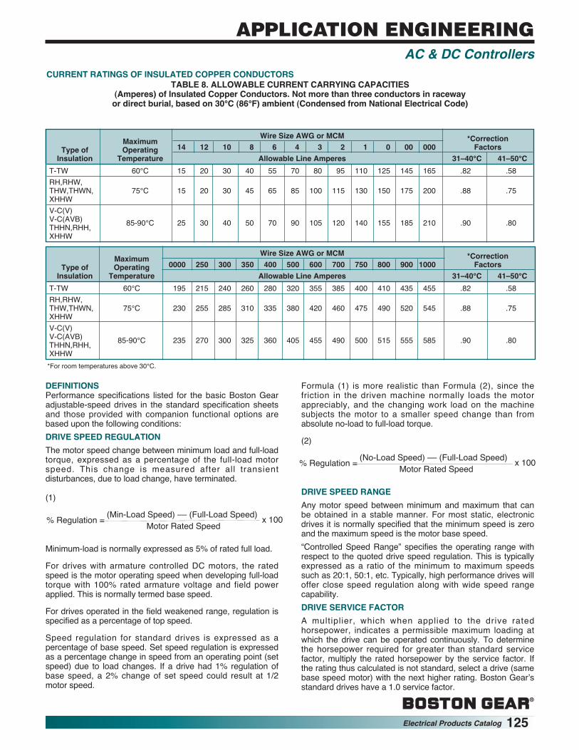
CURRENT RATINGS OF INSULATED COPPER CONDUCTORSTABLE 8. ALLOWABLE CURRENT CARRYING CAPACITIES
(Amperes) of Insulated Copper Conductors. Not more than three conductors in raceway or direct burial, based on 30°C (86°F) ambient (Condensed from National Electrical Code)
MaximumWire Size AWG or MCM *Correction
Type of Operating 14 12 10 8 6 4 3 2 1 0 00 000 FactorsInsulation Temperature Allowable Line Amperes 31–40°C 41–50°C
T-TW 60°C 15 20 30 40 55 70 80 95 110 125 145 165 .82 .58RH,RHW,THW,THWN, 75°C 15 20 30 45 65 85 100 115 130 150 175 200 .88 .75XHHWV-C(V)V-C(AVB) 85-90°C 25 30 40 50 70 90 105 120 140 155 185 210 .90 .80THHN,RHH,XHHW
MaximumWire Size AWG or MCM *Correction
Type of Operating 0000 250 300 350 400 500 600 700 750 800 900 1000 FactorsInsulation Temperature Allowable Line Amperes 31–40°C 41–50°C
T-TW 60°C 195 215 240 260 280 320 355 385 400 410 435 455 .82 .58RH,RHW,THW,THWN, 75°C 230 255 285 310 335 380 420 460 475 490 520 545 .88 .75XHHWV-C(V)V-C(AVB) 85-90°C 235 270 300 325 360 405 455 490 500 515 555 585 .90 .80THHN,RHH,XHHW
*For room temperatures above 30°C.
DEFINITIONSPerformance specifications listed for the basic Boston Gearadjustable-speed drives in the standard specification sheetsand those provided with companion functional options arebased upon the following conditions:DRIVE SPEED REGULATIONThe motor speed change between minimum load and full-loadtorque, expressed as a percentage of the full-load motorspeed. This change is measured after all transientdisturbances, due to load change, have terminated.
(1)
Minimum-load is normally expressed as 5% of rated full load.
For drives with armature controlled DC motors, the ratedspeed is the motor operating speed when developing full-loadtorque with 100% rated armature voltage and field powerapplied. This is normally termed base speed.
For drives operated in the field weakened range, regulation isspecified as a percentage of top speed.
Speed regulation for standard drives is expressed as apercentage of base speed. Set speed regulation is expressedas a percentage change in speed from an operating point (setspeed) due to load changes. If a drive had 1% regulation ofbase speed, a 2% change of set speed could result at 1/2motor speed.
Formula (1) is more realistic than Formula (2), since thefriction in the driven machine normally loads the motorappreciably, and the changing work load on the machinesubjects the motor to a smaller speed change than fromabsolute no-load to full-load torque.
(2)
DRIVE SPEED RANGEAny motor speed between minimum and maximum that canbe obtained in a stable manner. For most static, electronicdrives it is normally specified that the minimum speed is zeroand the maximum speed is the motor base speed.“Controlled Speed Range” specifies the operating range withrespect to the quoted drive speed regulation. This is typicallyexpressed as a ratio of the minimum to maximum speedssuch as 20:1, 50:1, etc. Typically, high performance drives willoffer close speed regulation along with wide speed rangecapability.DRIVE SERVICE FACTORA multiplier, which when applied to the drive ratedhorsepower, indicates a permissible maximum loading atwhich the drive can be operated continuously. To determinethe horsepower required for greater than standard servicefactor, multiply the rated horsepower by the service factor. Ifthe rating thus calculated is not standard, select a drive (samebase speed motor) with the next higher rating. Boston Gear’sstandard drives have a 1.0 service factor.
(Min-Load Speed) –– (Full-Load Speed)Motor Rated Speed% Regulation = x 100
(No-Load Speed) –– (Full-Load Speed)Motor Rated Speed% Regulation = x 100

®
126 Electrical Products Catalog
STEADY-STATE REGULATIONThe regulated value due to the following variation in operatingparameters occurring independently or simultaneously. (Loadremaining constant for speed and voltage regulators.
TEMPERATUREA change in ambient temperature produces a change in thecontrol variable expressed as a percentage change for aspecified temperature change of ±10°C. All standard units aredesigned to operate with a maximum enclosure interiortemperature of 55°C surrounding the regulator powerconversion module.TRANSIENT DEVIATIONA momentary speed change from a speed set point, occurringat the result of a specified rate of load change. Performance isdependent on load inertia, motor inertia, load friction, etc.
TRANSIENT RESPONSE TIMETime required to recover and maintain speed within thespecified regulation tolerance after a specified change in load.Performance is dependent on load inertia, motor inertia, loadfriction, etc.RANDOM DRIFTA change from initial set speed during an unchanging loadcondition over specified time period with constant referenceinput, constant temperature, constant line voltage, andconstant line frequency. Equipment must be operating at aspecified ambient condition for a warm-up of one hour beforethe drift specification is applicable. Drift is specified as apercentage change (may be plus or minus) of base speed,unless otherwise stated. Drift is caused by random changes inoperating characteristics of drive components.DISPLACEMENT POWER FACTORThe ratio of the active power of the fundamental wave to theapparent power of the fundamental wave in rms voltamperes.Displacement power factor is the power factor for whichelectric power utility companies charge penalties for low powerfactor.CALCULATED POWER FACTORExpressed by the formula: Watts = 3 × E Line (rms) × I Line(rms) × Cos θ (Power-Factor), represents the ratio of totalwatts input to total rms voltamperes input. This considers theharmonic content of line input, as well as the fundamentalwave of the line, and is always lower than the displacementpower factor.
VARIABLE VARIATION RANGEAC Supply Voltage 10% with rate of ±10% of nominal
change not to exceed voltage2.5% per second
AC Supply 2 Hz variation with 58-62 HzFrequency rate of change (60 nominal)
not to exceed 2.5% 48.5-51.5 Hzper second (50 nominal)
Ambient Temperature 15°C 0 to 40°C Random Drift 8 hour period after
1 hour warmup
APPLICATION ENGINEERINGAC & DC Controllers

®
Electrical Products Catalog 127
NEMA DEFINITIONSExtracted from NEMA Standard (ICS-110)ENCLOSURES DESCRIPTIONNEMA 1 General Purpose — Indoor.
Intended for use indoors, primarily toprevent accidental contact of personnel withthe enclosed equipment. In addition, theyprovide protection against falling dirt.
NEMA 3 Dusttight, Raintight and Sleet (Ice)Resistant – Outdoor.Intended for use outdoors to protect theenclosed equipment against windblowndust and water. They are not sleet (ice)proof.
NEMA 3R Rainproof and Sleet (Ice) Resistant –Outdoor.Intended for use outdoors to protect theenclosed equipment against rain. They arenot dust, snow, nor sleet (ice) proof.
NEMA 3S Dusttight, Raintight and Sleet (Ice) Proof– Outdoor.Intended for use outdoors to protect theenclosed equipment against windblowndust and water and to provide for itsoperation when the enclosure is covered byexternal ice or sleet. Does not protect theenclosed equipment against malfunctionresulting from internal icing.
NEMA 4 Watertight and Dusttight – Indoor.Intended for use indoors to protect theenclosed equipment against splashingwater, seepage of water, falling or hose-directed water, and severe externalcondensation.
NEMA 4X Watertight and Dusttight – Indoor.Same provisions as NEMA 4 enclosuresand, in addition, are corrosion resistant.
NEMA 5 Superseded by NEMA 12.NEMA 6 Submersible, Watertight, Dusttight and
Sleet (Ice) Resistant – Indoor andOutdoor.Intended for use indoors or outdoors whereoccasional submersion is encountered.
NEMA 12 Industrial Use – Dusttight andDriptight – Indoor.Intended for use indoors to protect theenclosed equipment against fibers,flyings, lint, dust and dirt, and lightsplashing, seepage, drippings andexternal condensation of non-corrosiveliquids.
NEMA 13 Oiltight and Dusttight – Indoor.Intended for use indoors primarily tohouse pilot devices such as limitswitches, foot switches, pushbuttons,selector switches, pilot lights, etc., andto protect these devices against lint anddust, seepage, external condensation,and spraying of water, oil or coolant.
ENCLOSURES DESCRIPTIONFOR HAZARDOUSLOCATIONS The term “explosion-proof” has been so
loosely applied that NEMA deprecatesits use. As defined by the NationalElectrical Code, the term “explosion-proof” applies only to NEMA 7 and 10enclosures which, when properlyinstalled and maintained, are designedto contain an internal explosion withoutcausing external hazard.Intended for use indoors, in the atmos-pheres and locations defined as Class Iand Group A, B, C or D in the NationalElectrical Code. The letters indicate thegas or vapor in the hazardous location.Intended for use indoors in theatmospheres defined as Class II andGroup E, F or G in the National ElectricalCode. The letters E, F or G indicate thedust in the hazardous location.
NEMA 10 Designed to meet the requirements ofthe U.S. Bureau of Mines which relate toatmospheres containing mixtures ofmethane and air, with or without coaldust.
NEMA 7, Class IGroup A, B,C, or D
NEMA 9, Class llGroup E, F, or G
APPLICATION ENGINEERINGElectrical Enclosures