Embed Size (px)
Citation preview
DF-52365:A1 • 08/25/09 — Page 1 of 6
CMF-300-6Six Circuit Supervised Control Module and SYNC-1 Accessory Card
Addressable Devices
DF-52365:A1 • E-920
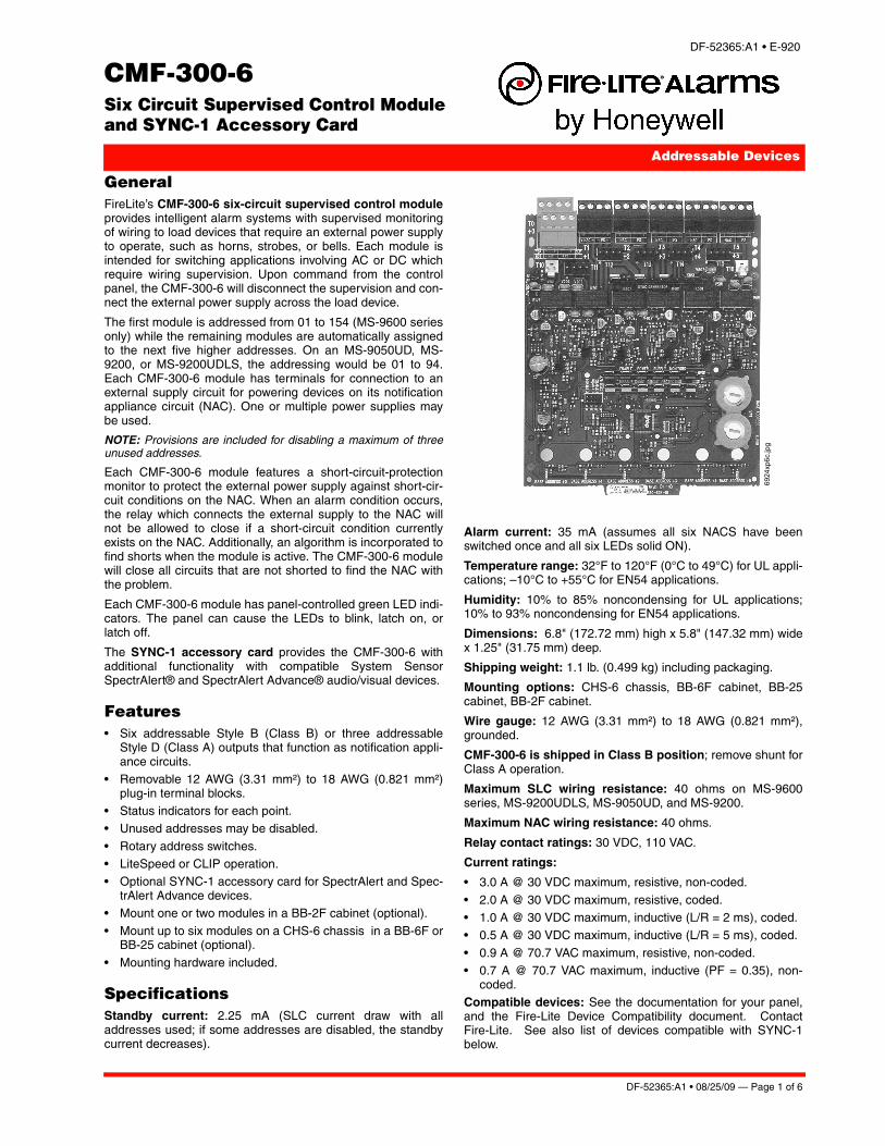
GeneralFireLite’s CMF-300-6 six-circuit supervised control moduleprovides intelligent alarm systems with supervised monitoringof wiring to load devices that require an external power supplyto operate, such as horns, strobes, or bells. Each module isintended for switching applications involving AC or DC whichrequire wiring supervision. Upon command from the controlpanel, the CMF-300-6 will disconnect the supervision and con-nect the external power supply across the load device.
The first module is addressed from 01 to 154 (MS-9600 seriesonly) while the remaining modules are automatically assignedto the next five higher addresses. On an MS-9050UD, MS-9200, or MS-9200UDLS, the addressing would be 01 to 94.Each CMF-300-6 module has terminals for connection to anexternal supply circuit for powering devices on its notificationappliance circuit (NAC). One or multiple power supplies maybe used.
NOTE: Provisions are included for disabling a maximum of threeunused addresses.
Each CMF-300-6 module features a short-circuit-protectionmonitor to protect the external power supply against short-cir-cuit conditions on the NAC. When an alarm condition occurs,the relay which connects the external supply to the NAC willnot be allowed to close if a short-circuit condition currentlyexists on the NAC. Additionally, an algorithm is incorporated tofind shorts when the module is active. The CMF-300-6 modulewill close all circuits that are not shorted to find the NAC withthe problem.
Each CMF-300-6 module has panel-controlled green LED indi-cators. The panel can cause the LEDs to blink, latch on, orlatch off.
The SYNC-1 accessory card provides the CMF-300-6 withadditional functionality with compatible System SensorSpectrAlert® and SpectrAlert Advance® audio/visual devices.
Features• Six addressable Style B (Class B) or three addressable
Style D (Class A) outputs that function as notification appli-ance circuits.
• Removable 12 AWG (3.31 mm²) to 18 AWG (0.821 mm²)plug-in terminal blocks.
• Status indicators for each point.• Unused addresses may be disabled.
• Rotary address switches. • LiteSpeed or CLIP operation.• Optional SYNC-1 accessory card for SpectrAlert and Spec-
trAlert Advance devices.• Mount one or two modules in a BB-2F cabinet (optional).
• Mount up to six modules on a CHS-6 chassis in a BB-6F orBB-25 cabinet (optional).
• Mounting hardware included.
SpecificationsStandby current: 2.25 mA (SLC current draw with alladdresses used; if some addresses are disabled, the standbycurrent decreases).
Alarm current: 35 mA (assumes all six NACS have beenswitched once and all six LEDs solid ON).
Temperature range: 32°F to 120°F (0°C to 49°C) for UL appli-cations; –10°C to +55°C for EN54 applications.
Humidity: 10% to 85% noncondensing for UL applications;10% to 93% noncondensing for EN54 applications.
Dimensions: 6.8" (172.72 mm) high x 5.8" (147.32 mm) widex 1.25" (31.75 mm) deep.
Shipping weight: 1.1 lb. (0.499 kg) including packaging.
Mounting options: CHS-6 chassis, BB-6F cabinet, BB-25cabinet, BB-2F cabinet.
Wire gauge: 12 AWG (3.31 mm²) to 18 AWG (0.821 mm²),grounded.
CMF-300-6 is shipped in Class B position; remove shunt forClass A operation.
Maximum SLC wiring resistance: 40 ohms on MS-9600series, MS-9200UDLS, MS-9050UD, and MS-9200.
Maximum NAC wiring resistance: 40 ohms.
Relay contact ratings: 30 VDC, 110 VAC.
Current ratings:
• 3.0 A @ 30 VDC maximum, resistive, non-coded.
• 2.0 A @ 30 VDC maximum, resistive, coded.• 1.0 A @ 30 VDC maximum, inductive (L/R = 2 ms), coded.• 0.5 A @ 30 VDC maximum, inductive (L/R = 5 ms), coded.
• 0.9 A @ 70.7 VAC maximum, resistive, non-coded.• 0.7 A @ 70.7 VAC maximum, inductive (PF = 0.35), non-
coded.Compatible devices: See the documentation for your panel,and the Fire-Lite Device Compatibility document. ContactFire-Lite. See also list of devices compatible with SYNC-1below.
6924
xp6c
.jpg
Page 2 of 6 — DF-52365:A1 • 08/25/09
SYNC-1 Accessory CardThe SYNC-1 accessory card is designed to operate with theCMF-300-6. It works with the SpectrAlert and the SpectrAlertAdvance series of horns, strobes, and horn/strobes to providea means of synchronizing the temporal-coded horns; synchro-nizing the one-second flash timing of the strobe; and silencingthe horns of the horn/strobe combination over a two-wire cir-cuit while leaving the strobes active. Each SYNC-1 accessorycard is capable of synchronizing six Class B circuits or threeClass A circuits.
Maximum load on a loop: 3 A.
Operating temperature: 32°F to 120°F (0°C to 49°C).
Wire size: 12 to 18 AWG (3.31 to 0.821 mm²).
Operating voltage range: 11 to 30 VDC FWR, filtered orunfiltered. Refer to notification appliance installation instruc-tions for number of notification appliances and wire size.
Compatible A/V devices: The SYNC-1 Accessory Card iscompatible with all System Sensor SpectrAlert and SpectrAlertAdvance Audio Visual Devices that have synchronizationcapability. Other manufacturers may be supported as well.Please refer to the latest Device Compatibility Document,PN 15384.
NOTE: *SpectrAlert and SpectrAlert Advance products utilizingSYNC-1 module below.
Product Line InformationCMF-300-6: Six-circuit supervised control module.
CMF-300-6A: Same as above with ULC Listing.
SYNC-1: Optional accessory card for synchronization of com-patible System Sensor SpectrAlert horns, strobes, and horn/strobes.
BB-2F: Optional cabinet for one or two modules. Dimensions,DOOR: 9.234" (23.454 cm) wide (9.484" [24.089 cm] includinghinges), x 12.218" (31.0337 cm) high, x 0.672" (1.7068 cm)deep; BACKBOX: 9.0" (22.860 cm) wide (9.25" [23.495 cm]including hinges), x 12.0" (30.480 cm) high x 2.75" (6.985 cm);CHASSIS (installed): 7.150" (18.161 cm) wide overall x7.312" (18.5725 cm) high interior overall x 2.156" (5.4762 cm)deep overall.
BB-6F: Optional cabinet for up to six modules mounted onCHS-6 chassis (below). Dimensions, DOOR: 24.0" (60.96cm) wide x 12.632" (32.0852 cm) high, x 1.25" (3.175 cm)deep, hinged at bottom; BACKBOX: 24.0" (60.96 cm) wide x12.550" (31.877 cm) high x 5.218" (13.2537 cm) deep.
CHS-6: Chassis, mounts up to six modules in the BB-6F cabi-net.
Agency Listings and ApprovalsThese listings and approvals apply to the modules specified inthis document. In some cases, certain modules or applicationsmay not be listed by certain approval agencies, or listing maybe in process. Consult factory for latest listing status.
• UL Listed: S2424• ULC Listed: S2424• MEA Listed: 55-02-E / 226-03-E (SYNC-1)
• FM Approved (Local Protective Signaling)• CSFM: 7300-0075:205 7300-1209:219 (SYNC-1) • Maryland State Fire Marshal: Permit # 2106 (CMF-300-6)
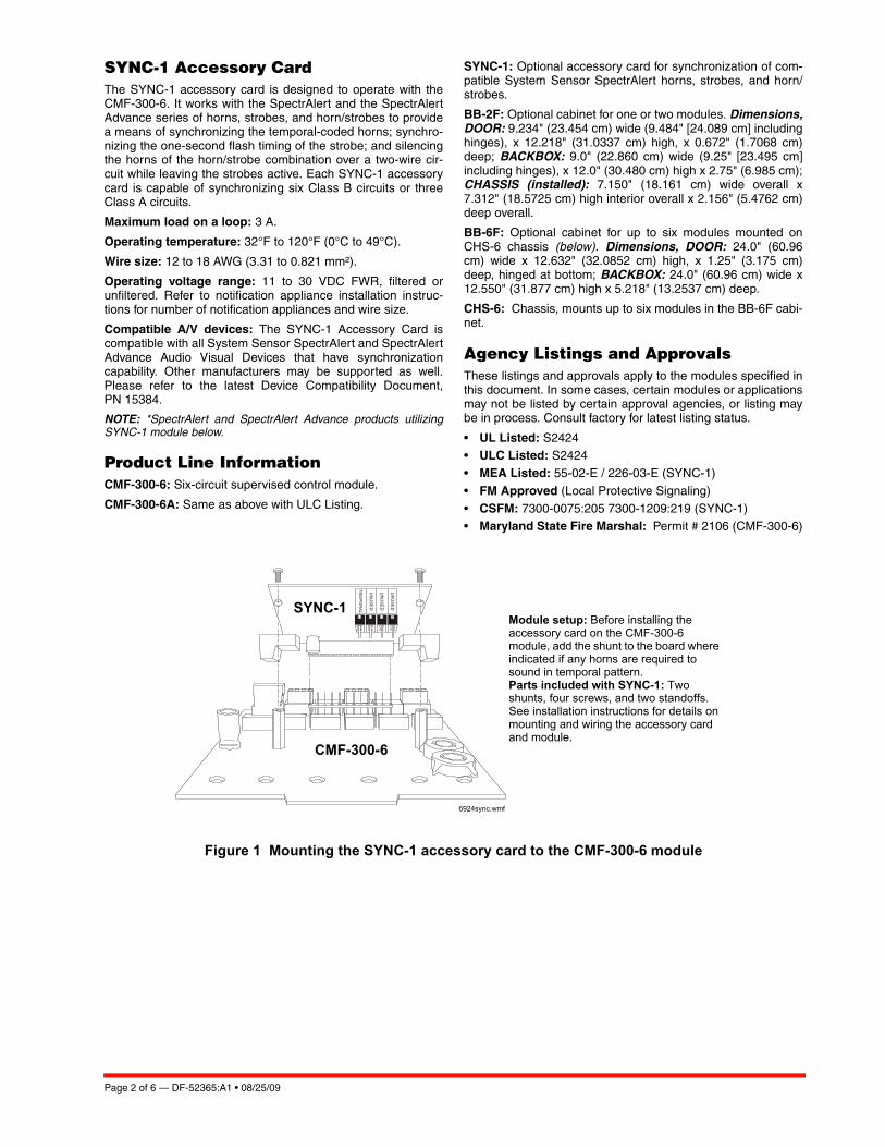
Figure 1 Mounting the SYNC-1 accessory card to the CMF-300-6 module
Module setup: Before installing the accessory card on the CMF-300-6 module, add the shunt to the board where indicated if any horns are required to sound in temporal pattern.Parts included with SYNC-1: Two shunts, four screws, and two standoffs. See installation instructions for details on mounting and wiring the accessory card and module.
6924sync.wmf
CMF-300-6
SYNC-1
DF-52365:A1 • 08/25/09 — Page 3 of 6
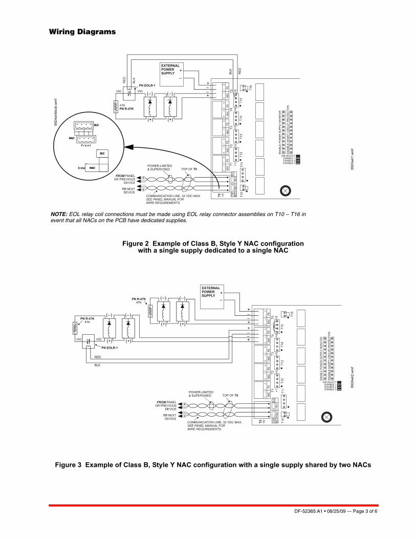
Wiring Diagrams
Figure 2 Example of Class B, Style Y NAC configuration with a single supply dedicated to a single NAC
Figure 3 Example of Class B, Style Y NAC configuration with a single supply shared by two NACs
NOTE: EOL relay coil connections must be made using EOL relay connector assemblies on T10 – T16 inevent that all NACs on the PCB have dedicated supplies.
6924
wir1
.wm
f
6924
wirb
lock
.wm
f
6924
wir2
.wm
f
Page 4 of 6 — DF-52365:A1 • 08/25/09
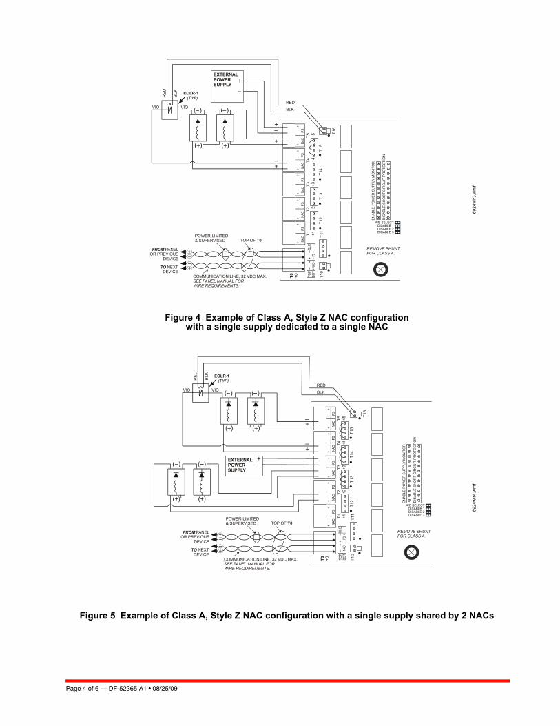
Figure 4 Example of Class A, Style Z NAC configuration with a single supply dedicated to a single NAC
Figure 5 Example of Class A, Style Z NAC configuration with a single supply shared by 2 NACs
6924
wir3
.wm
f69
24w
ir4.w
mf
DF-52365:A1 • 08/25/09 — Page 5 of 6
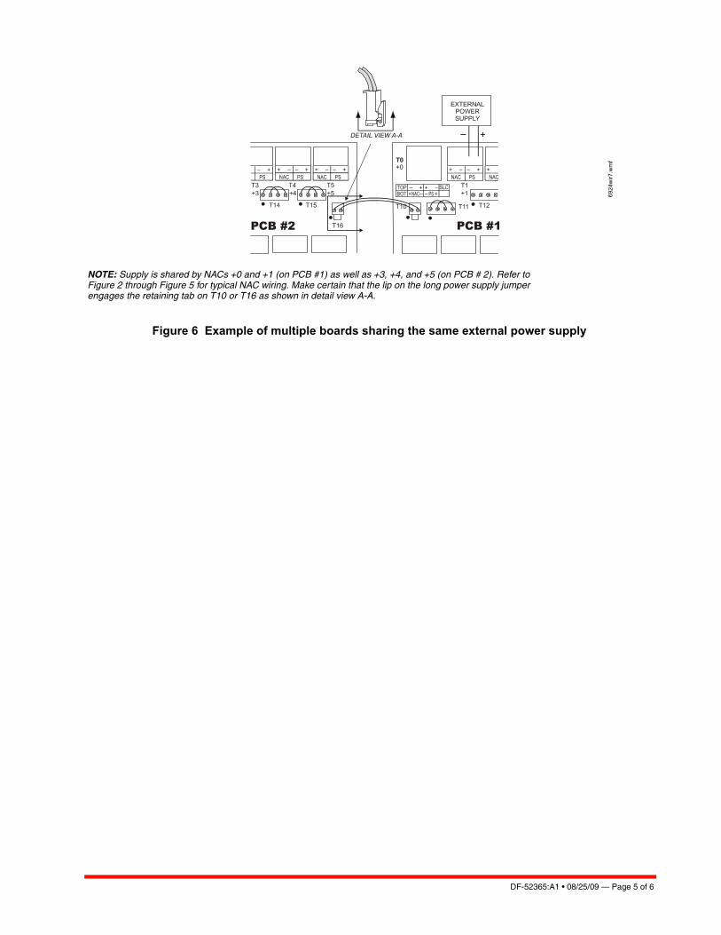
Figure 6 Example of multiple boards sharing the same external power supply
6924
wir7
.wm
f
NOTE: Supply is shared by NACs +0 and +1 (on PCB #1) as well as +3, +4, and +5 (on PCB # 2). Refer toFigure 2 through Figure 5 for typical NAC wiring. Make certain that the lip on the long power supply jumperengages the retaining tab on T10 or T16 as shown in detail view A-A.

Page 6 of 6 — DF-52365:A1 • 08/25/09
This document is not intended to be used for installation purposes. We try to keep our product information up-to-date and accurate.
We cannot cover all specific applications or anticipate all requirements. All specifications are subject to change without notice.
For more information, contact Fire•Lite Alarms. Phone: (800) 627-3473, FAX: (877) 699-4105.www.firelite.com
LiteSpeed®, SpectrAlert®, SpectrAlert Advance®, and System Sensor®are registered trademarks of Honeywell International Inc. ©2007 by Honeywell International Inc. All rights reserved. Unauthorized useof this document is strictly prohibited.
Made in the U.S. A.