Embed Size (px)
Citation preview

Purchasing Services Post Office Box 2570
Waco, Texas 76702-2570 Phone: 254-750-6640
Fax: 254-750-8063 [email protected]
CITY OF WACO www.waco-texas.com
Date: 08/18/2016 RFB No: 2016-036 Commodity: Waco Riverwalk Extension – Phase 2a Buyer: Mr. Kasey Gamblin
Closing Time: 2:00 P.M. CST, Thursday, August 25, 2016 Opening Time: 2:01 P.M. CST, Thursday, August 25, 2016
Bid Opening Location: Operations Center, Purchasing Services Office, 1415 N. 4th St., Waco, TX 76707 ______________________________________________________
Addendum No: 1
The above-mentioned Bid invitation has been changed in the following manner. Sign and return addendum to the Purchasing Office by the closing time and date with your RFB response. Returning this page signed by your authorized agent will serve to acknowledge this change. All other requirements of the invitation remain unchanged. If you have any questions, please call or stop by the Purchasing Office at the above address.
1. See Attachment 1 with questions and answers from the Thursday, August11, 2016 Pre-bid, or that have been submitted in writing by potentialbidders.
2. See Attachment 2 with the Geotechnical Report.
Firm:_____________________________________________________________________________________
Address___________________________________________________________________________________
Signature of Person Authorized to Sign Bid:______________________________________________________________________
Signor's Name and Title (print or type):_____________________________________________________________________________
E-mail Address:____________________________________________________________________________
Date:____________________Telephone:___________________________Fax:_________________________
City of Waco RFB 2016-036 Waco Riverwalk Extension - Phase 2a Addendum 1
Page 1 of 77

HALFF AS SOCI A TES, INC.
TEL (512) 942-6232 WWW.HALFF.COMGEORGETOWN, TX 78626 F A X (512) 869-0089
TWO SIERRA WAY, SUITE 105
August 17, 2016
AVO 29736
2016-036
Mr. Tom Balk, LA
City of Waco Parks & Recreation Department
PO Box 2570
Waco, TX 76702
RE: Waco Riverwalk Extension (Phase 2A)
Bidding – Addendum 1
Mr. Balk,
Based on the non-mandatory pre-bid meeting held today at the Operations Center Conference Room, several items were
brought up that require clarification or modifications to either the plan set or the specifications. Below are descriptions of
the changes:
1. What are the Minority, DBE Requirements and how important will those be?:
The DBE goals are set at 4.0% for this project and can be found on Page 146 of the Project Manual and will be
required to comply with Federal and State requirements.
2. What is the Construction Budget?
The Engineer’s Estimate of Probable Cost projects a total construction cost of $3,534,178.00 (base bid: $3,243,768 +
add alternate 1: $290,410).
Project funding consistent with the Engineer’s Estimate of Probable Cost has been identified through a $3.38M
Federal Grant and additional local funds.
3. Are the columns part of the bents or drill shafts?
The columns shown on the plans are to be calculated and included in the CY calculation for bid item A-50-CL C
CONC (BENT) (HPC). The ‘H’ value shown in profiles represents estimated column height. The drill shaft depths
are shown as ‘XX’ DS’ and represented as bid items A-47 and A-48 Drilled Shafts.
4. Who will handle the inspections?
Inspections will be coordinated through the City inspector and will contain multiple inspections. TxDOT is required
to inspect or attend monthly meetings at the project site.
5. What should happen with the soils removed from drilling?
Contractor will be required to haul off all soil removed from any river drilling.
6. Will a contractor be able to create a temporary structure that will allow for the construction of a portion of the project
from land?
The Nationwide Permit (NWP) authorizes temporary structures, fills, and work necessary to construct the linear
transportation project. As part of the permitting process, this temporary amount is not to exceed 0.26 acres of
ATTACHMENT 1
City of Waco RFB 2016-036 Waco Riverwalk Extension - Phase 2a Addendum 1
Page 2 of 77

Page 2
delineated wetland. Contractor is responsible for managing these temporary impacts based on desired means and
methods. Appropriate measures must be taken to maintain normal downstream flows and minimize flooding to the
maximum extent practicable, when temporary structures, work, and discharges, including cofferdams, are necessary
for construction activities, access fills, or dewatering of construction sites. Additional coordination prior to
construction will take place to identify all available locations.
7. Detail 4/S3.03 is calling for a “threaded weldable rebar coupler” with “threaded rebar”. In lieu of the coupler, can we
weld the rebar directly to the edge angle?
Contractor can weld the rebar directly to the angle, but any rebar that will be welded has to meet weldable rebar
standards (ASTM A706) rather than the typical ASTM A615 rebar that is used for the rest of the reinforcing.
8. Replace Sheet C2.11-Civil Details of the plans with the updated details C6 and C8 detailing the Concrete Pour
Detail for expansion and contraction joints on the bridge.
9. Replacing Bid Sheet. Updated quantity for line item A-53 and removed line item A-56.
10. Attached Plan Graphics of Icon Shade Structure that are displayed in plan set sheets L1.05 & L1.06.
11. Replaced specification COW 7.301 with updated specification to include updated Icon Shade Structure
Specifications.
If you have any questions, please do not hesitate to give me a call.
Thank you.
HALFF ASSOCIATES, INC.
Shawn Bertram, P.E.
Public Infrastructure Manager
City of Waco RFB 2016-036 Waco Riverwalk Extension - Phase 2a Addendum 1
Page 3 of 77

GROUT.
FACE. SET DOWEL IN EPOXY
HOLE PERPENDICULAR TO
DRILL SLIGHTLY OVERSIZED
MATERIAL
EXPANSION JOINT
PREMOLDED
1/2"
N.T.S.
PROP. REINFORCING BAR
EXIST. CONC. PROP. CONC.
T/2
T
EXPANSION
•"
N.T.S.
24"
1/2" DIA. SMOOTH DOWEL
12"
CRACKS OR JOINTS.
REINFORCING BARS WILL BE AT LEAST 12" FROM EXIST.
BE LESS THAN 24" AND NOT MORE THAN 36". HOWEVER,
NOTE: NORMAL SPACING OF REINFORCING BARS WILL NOT
LUBRICATE THIS END
DOWEL DETAIL
JOINTS.
AT CONTRACTION
TO BE USED ONLY
NOTE:
N.T.S.
‚"
„"
T/2
T
24"
DEFORMED DOWEL
24" No.4 BAR
AT 12" O.C.
N.T.S.
CONCRETE POUR DETAIL
(SEE EXPANSION JOINT DETAIL)
PROPSED EXPANSION JOINT
JOINT DETAILS
EXPANSION JOINT
CONSTRUCTION JOINT
C6
C7
SAWED CONTRACTION JOINTN.T.S.
TRAIL THICKNESS
T= HEAVY DUTY
TRAIL THICKNESS
T= HEAVY DUTY
T
SAWED JOINT
N.T.S.
WITHOUT SEALANT
SL-1
SL-1
JOINT FILLER
(EXP REDWOOD)
‚"
1"
WITH LUBRICATED EXPANSION CAP
FULL LENGTH DOWEL SLEEVE (ONE SIDE ONLY)
C8
CIVIL DETAILS
C2.11
WID
TH
OF
TR
AIL
WIDTH OF TRAIL
SPACED MAX AT 10' (TYP)
PROPOSED CONTRACTION JOINT
1/2"
3/8" COMPOUND
JOINT SEALING
3/8"
AT 18" O.C. MAX
SMOOTH DOWEL
24" No.4 BAR
TRAIL THICKNESS
T= HEAVY DUTY
SILT CURTAIN DETAIL
AB
AS
CO
TY
PE 3
OR
SIMIL
AR
AP
PR
OV
ED
BY
EN
GIN
EE
R
C9
SAWED CONTRACTION JOINTN.T.S.
TRAIL THICKNESS
T= HEAVY DUTY
T
SAWED JOINT
‚"
1"WITH SEALANT
FINISHED GRADE OF TRAIL.
EXPANSION JOINT 3/8" BELOW
COLOR SAMPLES. INSTALL REDWOOD
CONTRACTOR TO SUBMIT
SYSTEM OR APPROVED EQUIVALENT.
SONNEBORN SONOLASTIC SEALANT
B. FILL EXPANSION JOINTS WITH
PLACE 6" MIN. FROM EDGE OF TRAIL.
@ 18" O.C. MAX WITH LUBRICATED CAP.
A. #4 X 24" LONG SMOOTH DOWEL
NOTES:
LOCATION ONLY)
WITH COLORED SEALANT (BRIDGE
PROPOSED CONTRACTION JOINT
10' (BRIDGE ONLY)
50' - MAX SPACING EXPANSION JOINTS ON BRIDGE40' - MAX SPACING EXPANSION JOINTS
CONSTRUCT EXPANSION JOINT
LOCATIONS, CONTRACTOR SHALL
B. ON NON ARMOR JOINT BENT
POSTS.
LENGTH TO AVOID CONFLICT WITH RAIL
SHALL BE LOCATED MID RAIL PANEL
A. EXPANSION AND CONTRACTION JOINTS
BRIDGE NOTES:
Sheet Number
Sheet Title
Checked By:
Drawn By:
Project No.:
Issued:
Scale:
FA
X (512) 869-0
089
TE
L (512) 942-6
232
GE
OR
GE
TO
WN, T
EX
AS 78626-7
574
TW
O SIE
RR
A W
AY, S
UIT
E 1
05
TB
PE #
F-3
12
WA
CO, T
EX
AS 76707-3
859
201 W
ES
T W
AC
O D
R.
RE
VISIO
ND
AT
EB
YN
O.
TE
XA
S
ST
AT
E
CO
UN
TY
DV.
NO.
FE
D.
RD.
DIS
TRIC
T N
O.
ST
AT
E
NO.
CO
NT
RO
LN
O.
SE
CTIO
NN
O.
JO
B
HIG
HW
AY N
O.
FE
DE
RA
L AID P
ROJE
CT N
O.
MC
LE
NN
AN
22
WA
C0909
165
CS
EX
TE
NSIO
N (P
HA
SE 2
A)
WA
CO RIV
ER
WA
LK
AS NOTED
29736
8/17/2016
HA
HA
STP 2
014(1
00)T
E
City of Waco RFB 2016-036 Waco Riverwalk Extension - Phase 2a Addendum 1
Page 4 of 77

RFB for Riverwalk Extension [07/20/2016] Page 13 of 167
CITY OF WACO
Purchasing Services
Bid Sheet
BID NO: 2016-036
BIDDER: DATE:
AUTHORIZED SIGNATURE:
- - - - - - - - - - - - - - - - - - - - - - - - - - - - - - - - - - - - - - - - - - - - - - - - - - - - - - - - - - - - - - -
1. Price: Includes all labor, materials, and equipment to complete project.
2. Completion time to 425 calendar days after notice to proceed.
3. In submitting this bid, I certify:
a. Items bid are in exact accordance with specifications, unless noted in bid.
b. Prices in this bid have been arrived at independently, without consultation or
agreement with any competitor for the purpose of restricting competition. - - - - - - - - - - - - - - - - - - - - - - - - - - - - - - - - - - - - - - - - - - - - - - - - - - - - - - - - - - - - - - - - - - - - - - - - - - - -
Description/Specification Amount Bid
- - - - - - - - - - - - - - - - - - - - - - - - - - - - - - - - - - - - - - - - - - - - - - - - - - - - - - - Waco Riverwalk Extension (Phase 2A) Bid Items:
1. Waco Riverwalk Extension (Phase 2A) BASE BID items including approximately 0.6
mile concrete pedestrian and bicycle trail including concrete trail, pedestrian bridge,
grading, lighting, seating areas, signage, stone walls, landscaping, utilities including
electrical service and lighting along trail, and miscellaneous items, complete and in place
per enclosed plans and specifications.
UNIT PRICE SCHEDULE FOR Waco Riverwalk Extension (Phase 2A) Project
ITEM NO.
TECH SPEC
ESTIMATED QUANTITY UNIT ITEM DESCRIPTION & PRICE IN WORDS UNIT PRICE
IN FIGURES TOTAL
ESTIMATED PRICE
A-1 100-6002 21 STA PREP RIGHT OF WAY, the sum of ________________________dollars and _________________________cents per unit
$__________ $____________
A-2 104 6015 51 SY
REMOVING CONCRETE (SIDEWALKS), the sum of ________________________dollars and _________________________cents per unit
$__________ $____________
A-3 110 6001 257 CY EXCAVATION, the sum of ___________________________dollars and _________________________cents per unit
$__________ $____________
A-4 132 6003 391 CY
EMBANKMENT (FINAL) (ORD COMP) (TYP B), the sum of __________________________dollars and _________________________cents per unit
$__________
$____________
City of Waco RFB 2016-036 Waco Riverwalk Extension - Phase 2a Addendum 1
Page 5 of 77

RFB for Riverwalk Extension [07/20/2016] Page 14 of 167
UNIT PRICE SCHEDULE FOR Waco Riverwalk Extension (Phase 2A) Project
ITEM NO.
TECH SPEC
ESTIMATED QUANTITY UNIT ITEM DESCRIPTION & PRICE IN WORDS UNIT PRICE
IN FIGURES TOTAL
ESTIMATED PRICE
A-5 160 6003 789 SY
FURNISHING AND PLACING TOPSOIL (4”), the sum of ____________________________dollars and ________________________ cents per unit
$__________ $____________
A-6 162 6002 55 SY BLOCK SODDING, the sum of ____________________________dollars and ________________________ cents per unit
$__________ $____________
A-7 164 6021 231 SY
CELL FBR MLCH SEED (PERM) (RURAL) (SANDY), the sum of ____________________________dollars and ________________________ cents per unit
$__________ $____________
A-8 168 6001 13 MG
VEGETATIVE WATERING, the sum of ____________________________dollars and _________________________cents per unit
$__________ $____________
A-9 169 6004 503 SY
SOIL RETENTION BLANKETS (CL 1) (TY D), the sum of ____________________________dollars and _________________________cents per unit
$__________ $____________
A-10 169 6005 198 SY
SOIL RETENTION BLANKETS (CL 2) (TY E), the sum of ____________________________dollars and _________________________cents per unit
$__________ $____________
A-11 192 6015 788 LF
LANDSCAPE EDGE, the sum of ____________________________dollars and _________________________cents per unit
$__________ $____________
A-12 216 6001 5 HR
PROOF ROLLING, the sum of ____________________________dollars and _________________________cents per unit
$__________
$____________
City of Waco RFB 2016-036 Waco Riverwalk Extension - Phase 2a Addendum 1
Page 6 of 77

RFB for Riverwalk Extension [07/20/2016] Page 15 of 167
UNIT PRICE SCHEDULE FOR Waco Riverwalk Extension (Phase 2A) Project
ITEM NO.
TECH SPEC
ESTIMATED QUANTITY UNIT ITEM DESCRIPTION & PRICE IN WORDS UNIT PRICE
IN FIGURES TOTAL
ESTIMATED PRICE
A-13 496 6099 60 LF
REMOV STR (RAIL), the sum of ____________________________dollars and _________________________cents per unit
$__________ $____________
A-14 506 6002 30 LF
ROCK FILTER DAMS (INSTALL) (TY 2), the sum of ____________________________dollars and _________________________cents per unit
$__________ $____________
A-15 506 6011 30 LF
ROCK FILTER DAMS (REMOVE), the sum of ____________________________dollars and _________________________cents per unit
$__________ $____________
A-16 506 6020 300 SY
CONSTRUCTION EXITS (INSTALL) (TY 2), the sum of ____________________________dollars and _________________________cents per unit
$__________ $____________
A-17 506 6024 300 SY
CONSTRUCTION EXITS (REMOVE), for the sum of ____________________________dollars and _________________________cents per unit
$__________ $____________
A-18 506 6038 876 LF
TEMP SEDIMENT CONTROL FENCE (INSTALL), for the sum of ____________________________dollars and _________________________cents
$__________ $____________
A-19 506 6039 876 LF
TEMP SEDIMENT CONTROL FENCE (REMOVE), the sum of ____________________________dollars and _________________________cents per unit
$__________ $____________
A-20 COW 1.1
1 LS
RIVER SEDIMENT CONTROL, the sum of ____________________________dollars and _________________________cents per unit
$__________ $____________
A-21 752 6005 5 EA
TREE REMOVAL (4”-12” DIA), the sum of ____________________________dollars and _________________________cents per unit
$__________ $____________
City of Waco RFB 2016-036 Waco Riverwalk Extension - Phase 2a Addendum 1
Page 7 of 77

RFB for Riverwalk Extension [07/20/2016] Page 16 of 167
UNIT PRICE SCHEDULE FOR Waco Riverwalk Extension (Phase 2A) Project
ITEM NO.
TECH SPEC
ESTIMATED QUANTITY UNIT ITEM DESCRIPTION & PRICE IN WORDS UNIT PRICE
IN FIGURES TOTAL
ESTIMATED PRICE
A-22 COW 1.1
51 EA
INSTALL & REMOVE TREE PROTECTION, the sum of ____________________________dollars and _________________________cents per unit
$__________ $____________
A-23 531 6002 750 SY
CONC SIDEWALKS (5”), the sum of ____________________________dollars and _________________________cents per unit
$__________ $____________
A-24 COW 6.10
2,295 SF
ROCK RIPRAP, the sum of ____________________________dollars and _________________________cents per unit
$__________ $____________
A-25 432 6002 32 CY RIPRAP (CONC) (5”), the sum of ____________________________dollars and _________________________cents
$__________ $____________
A-26 COW 2.3
302 SY
DECOMPOSED GRANITE, the sum of ____________________________dollars and _________________________cents per unit
$__________ $____________
A-27 500 6001 1 LS
MOBILIZATION, the sum of ____________________________dollars and _________________________cents per unit
$__________ $____________
A-28 502 6001 12 MO
BARRICADES, SIGNS AND TRAFFIC HANDLING, the sum of ____________________________dollars and _________________________cents per unit
$__________ $____________
A-29 COW 4.801
2 EA
ADJUST WASTEWATER MANHOLE TO GRADE, the sum of ____________________________dollars and _________________________cents per unit
$__________ $____________
City of Waco RFB 2016-036 Waco Riverwalk Extension - Phase 2a Addendum 1
Page 8 of 77

RFB for Riverwalk Extension [07/20/2016] Page 17 of 167
UNIT PRICE SCHEDULE FOR Waco Riverwalk Extension (Phase 2A) Project
ITEM NO.
TECH SPEC
ESTIMATED QUANTITY UNIT ITEM DESCRIPTION & PRICE IN WORDS UNIT PRICE
IN FIGURES TOTAL
ESTIMATED PRICE
A-30 416 6002 40 LF
24” DIA DRILLED SHAFTS (LIGHT POLE BASE), the sum of ____________________________dollars and _________________________cents per unit
$__________ $____________
A-31 610 6002 1 EA
RELOCATE RD IL ASM, the sum of ____________________________dollars and _________________________cents per unit
$__________ $____________
A-32 618 6023 905 LF
CONDUIT PVC SCH. 40 2", the sum of ____________________________dollars and _________________________cents per unit
$__________ $____________
A-33 618 6046 40 LF
CONDUIT PVC SCH. 80 2", the sum of ____________________________dollars and _________________________cents per unit
$__________ $____________
A-34 618 6062 395 LF
CONDUIT RIGID METAL 3/4", the sum of ____________________________dollars and _________________________cents per unit
$__________ $____________
A-35 618 6064 1,520 LF
CONDUIT RIGID METAL 1", the sum of ____________________________dollars and _________________________cents per unit
$__________ $____________
A-36 620 6006 3,210 LF
ELEC. CONDUCTOR (NO. 10) INS GND, the sum of ____________________________dollars and _________________________cents per unit
$__________ $____________
A-37 620 6006 9,630 LF
ELEC. CONDUCTOR (NO. 10) INSULATED, the sum of ____________________________dollars and _________________________cents per unit
$__________ $____________
City of Waco RFB 2016-036 Waco Riverwalk Extension - Phase 2a Addendum 1
Page 9 of 77

RFB for Riverwalk Extension [07/20/2016] Page 18 of 167
UNIT PRICE SCHEDULE FOR Waco Riverwalk Extension (Phase 2A) Project
ITEM NO.
TECH SPEC
ESTIMATED QUANTITY UNIT ITEM DESCRIPTION & PRICE IN WORDS UNIT PRICE
IN FIGURES TOTAL
ESTIMATED PRICE
A-38 620 6010 120 LF
ELEC. CONDUCTOR (NO. 6) INSULATED, the sum of ____________________________dollars and _________________________cents per unit
$__________ $____________
A-39 624 6001 7 EA
GROUND BOX TY A (122311) W/APRON, the sum of ____________________________dollars and _________________________cents per unit
$__________ $____________
A-40 628 6032 1 EA
ELC SRV TY A 240/480 060 (NS) AL (E) PS (U),, the sum of ____________________________dollars and _________________________cents per unit
$__________ $____________
A-41 COW 9.101
24 EA
LIGHT FIXTURE (CITY OF WACO) TYPE A, the sum of ____________________________dollars and _________________________cents per unit
$__________ $____________
A-42 COW 9.101
6 EA
LIGHT FIXTURE (CITY OF WACO) TYPE C, the sum of ____________________________dollars and _________________________cents per unit
$__________ $____________
A-43 COW 9.101
2 EA
LIGHT FIXTURE (CITY OF WACO) TYPE E, the sum of ____________________________dollars and _________________________cents per unit
$__________ $____________
A-44 COW 9.101
4 EA
LIGHT FIXTURE (CITY OF WACO) TYPE F, the sum of ______________________dollars and _________________________cents per unit
$__________ $____________
A-45 416 6001 435 LF
18" DIA. DRILLED SHAFTS (WINGWALLS 1), the sum of ____________________________dollars and _________________________cents per unit
$__________ $____________
City of Waco RFB 2016-036 Waco Riverwalk Extension - Phase 2a Addendum 1
Page 10 of 77

RFB for Riverwalk Extension [07/20/2016] Page 19 of 167
UNIT PRICE SCHEDULE FOR Waco Riverwalk Extension (Phase 2A) Project
ITEM NO.
TECH SPEC
ESTIMATED QUANTITY UNIT ITEM DESCRIPTION & PRICE IN WORDS UNIT PRICE
IN FIGURES TOTAL
ESTIMATED PRICE
A-46 416 6002 392 LF
24" DIA. DRILLED SHAFTS (ABUTMENTS), the sum of ____________________________dollars and _________________________cents per unit
$__________ $____________
A-47 416 6004 979 LF
36" DIA. DRILLED SHAFTS (BENTS), the sum of ____________________________dollars and _________________________cents per unit
$__________ $____________
A-48 416 6006 239 LF
48" DIA. DRILLED SHAFTS (BENTS), the sum of ____________________________dollars and _________________________cents per unit
$__________ $____________
A-49 420 6014 122 CY
CL C CONC (ABUT) (HPC), the sum of ____________________________dollars and _________________________cents per unit
$__________ $____________
A-50 420 6026 290 CY
CL C CONC (BENT) (HPC), the sum of ____________________________dollars and _________________________cents per unit
$__________ $____________
A-51 COW 5.101
21,038 SF
5.5" CONC SLAB ON METAL DECK, the sum of ____________________________dollars and _________________________cents per unit
$__________ $____________
A-52 442 6004 273,500 LB
STR STEEL (ROLLED BEAM), the sum of ____________________________dollars and _________________________cents per unit
$__________ $____________
A-53 COW 6.601
2,950 LF
RAILING, the sum of ____________________________dollars and _________________________cents per unit
$__________ $____________
City of Waco RFB 2016-036 Waco Riverwalk Extension - Phase 2a Addendum 1
Page 11 of 77
RFB for Riverwalk Extension [07/20/2016] Page 20 of 167
UNIT PRICE SCHEDULE FOR Waco Riverwalk Extension (Phase 2A) Project
ITEM NO.
TECH SPEC
ESTIMATED QUANTITY UNIT ITEM DESCRIPTION & PRICE IN WORDS UNIT PRICE
IN FIGURES TOTAL
ESTIMATED PRICE
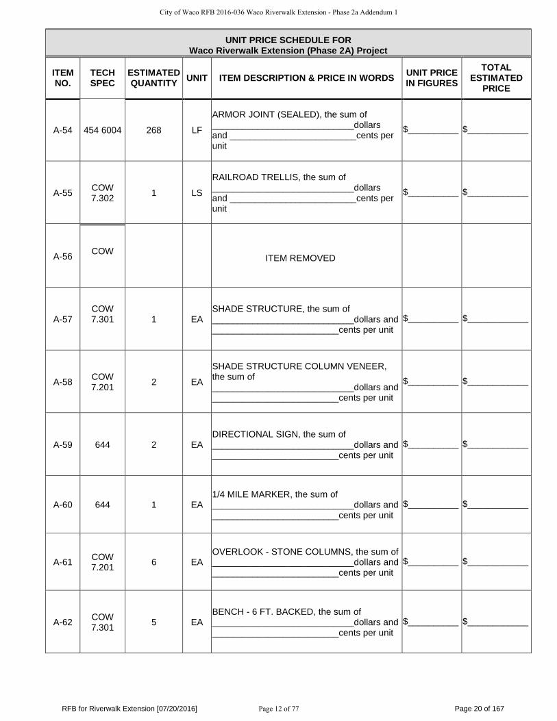
A-54 454 6004 268 LF
ARMOR JOINT (SEALED), the sum of ____________________________dollars and _________________________cents per unit
$__________ $____________
A-55 COW 7.302
1 LS
RAILROAD TRELLIS, the sum of ____________________________dollars and _________________________cents per unit
$__________ $____________
A-56 COW
ITEM REMOVED
A-57 COW 7.301
1 EA
SHADE STRUCTURE, the sum of ____________________________dollars and _________________________cents per unit
$__________ $____________
A-58 COW 7.201
2 EA
SHADE STRUCTURE COLUMN VENEER, the sum of ____________________________dollars and _________________________cents per unit
$__________ $____________
A-59 644 2 EA DIRECTIONAL SIGN, the sum of ____________________________dollars and _________________________cents per unit
$__________ $____________
A-60 644 1 EA 1/4 MILE MARKER, the sum of ____________________________dollars and _________________________cents per unit
$__________ $____________
A-61 COW 7.201
6 EA OVERLOOK - STONE COLUMNS, the sum of ____________________________dollars and _________________________cents per unit
$__________ $____________
A-62 COW 7.301
5 EA BENCH - 6 FT. BACKED, the sum of ____________________________dollars and _________________________cents per unit
$__________ $____________
City of Waco RFB 2016-036 Waco Riverwalk Extension - Phase 2a Addendum 1
Page 12 of 77

RFB for Riverwalk Extension [07/20/2016] Page 21 of 167
UNIT PRICE SCHEDULE FOR Waco Riverwalk Extension (Phase 2A) Project
ITEM NO.
TECH SPEC
ESTIMATED QUANTITY UNIT ITEM DESCRIPTION & PRICE IN WORDS UNIT PRICE
IN FIGURES TOTAL
ESTIMATED PRICE
A-63 COW 7.301
4 EA BENCH - 6 FT. BACKLESS, the sum of ____________________________dollars and _________________________cents per unit
$__________ $____________
A-64 COW 7.301
4 EA
TRASH RECEPTACLE WITH CONC. PAD, the sum of ____________________________dollars and _________________________cents per unit
$__________ $____________
TOTAL BASE BID Waco Riverwalk Extension (Phase 2A) $
City of Waco RFB 2016-036 Waco Riverwalk Extension - Phase 2a Addendum 1
Page 13 of 77

RFB for Riverwalk Extension [07/20/2016] Page 22 of 167
A1. ADD ALTERNATE ONE: Add alternate one including concrete trail from MLK Park to abandoned
railroad and sidewalk up to Franklin Ave. as shown on Plan sheets: including concrete sidewalk, grading,
lighting, landscaping and miscellaneous items per enclosed plans and specifications complete and in place:
UNIT PRICE SCHEDULE FOR Waco Riverwalk Extension (Phase 2A) Project
ITEM NO.
TECH SPEC
ESTIMATED QUANTITY UNIT ITEM DESCRIPTION & PRICE IN WORDS UNIT PRICE
IN FIGURES TOTAL
ESTIMATED PRICE
B-1 100 6002 14 STA PREP ROW, the sum of ________________________dollars and _________________________cents per unit
$__________ $____________
B-2 104 6015 39 SY REMOVING CONC (SIDEWALKS), the sum of ____________________________dollars and ________________________ cents per unit
$__________ $____________
B-3 110 6001 1,018 CY EXCAVATION, the sum of ____________________________dollars and ________________________ cents per unit
$__________ $____________
B-4 132 6003 72 CY
EMBANKMENT (FINAL) (ORD COMP) (TYP B), the sum of ____________________________dollars and _________________________cents per unit
$__________ $____________
B-5 160 6003 3,120 SY
FURNISHING AND PLACING TOPSOIL (4 IN), the sum of ____________________________dollars and _________________________cents per unit
$__________ $____________
B-6 162 6002 599 SY
BLOCK SODDING, the sum of ____________________________dollars and _________________________cents per unit
$__________ $____________
B-7 164 6021 1,979 SY
CELL FBR MULCH SEED (PERM) (RURAL) (SANDY), the sum of ____________________________dollars and _________________________cents per unit
$__________ $____________
City of Waco RFB 2016-036 Waco Riverwalk Extension - Phase 2a Addendum 1
Page 14 of 77

RFB for Riverwalk Extension [07/20/2016] Page 23 of 167
UNIT PRICE SCHEDULE FOR Waco Riverwalk Extension (Phase 2A) Project
ITEM NO.
TECH SPEC
ESTIMATED QUANTITY UNIT ITEM DESCRIPTION & PRICE IN WORDS UNIT PRICE
IN FIGURES TOTAL
ESTIMATED PRICE
B-8 168 6001 33 MG
VEGETATIVE WATERING, the sum of ____________________________dollars and _________________________cents per unit
$__________ $____________
B-9 169 6004 542 SY
SOIL RETENTION BLANKETS (CL 1) (TY D), the sum of ____________________________dollars and _________________________cents per unit
$__________ $____________
B-10 216 6001 2 HR
PROOF ROLLING, the sum of ____________________________dollars and _________________________cents per unit
$__________ $____________
B-11 506 6038 1,184 LF
TEMP SEDIMENT CONTROL FENCE (INSTALL), the sum of ____________________________dollars and _________________________cents per unit
$__________ $____________
B-12 506 6039 1,184 LF
TEMP SEDIMENT CONTROL FENCE (REMOVE), the sum of ____________________________dollars and _________________________cents per unit
$__________ $____________
B-13 752 6005 1 EA
TREE REMOVAL (4"-12" DIA), the sum of ____________________________dollars and _________________________cents per unit
$__________ $____________
B-14 COW 1.1
30 EA
INSTALL & REMOVE TREE PROTECTION, the sum of ____________________________dollars and _________________________cents per unit
$__________ $____________
B-15 416 6002 85 LF
24” DIA. Drilled Shafts (light pole base), the sum of ____________________________dollars and _________________________cents per unit
$__________ $____________
City of Waco RFB 2016-036 Waco Riverwalk Extension - Phase 2a Addendum 1
Page 15 of 77

RFB for Riverwalk Extension [07/20/2016] Page 24 of 167
UNIT PRICE SCHEDULE FOR Waco Riverwalk Extension (Phase 2A) Project
ITEM NO.
TECH SPEC
ESTIMATED QUANTITY UNIT ITEM DESCRIPTION & PRICE IN WORDS UNIT PRICE
IN FIGURES TOTAL
ESTIMATED PRICE
B-16 618 6023 1,305 LF CONDUIT PVC SCH. 40 2", the sum of ____________________________dollars and _________________________cents per unit
$__________ $____________
B-17 618 6064 115 LF CONDUIT RMC 3/4", the sum of ____________________________dollars and _________________________cents per unit
$__________ $____________
B-18 620 6006 1,620 LF
ELEC. CONDUCTOR (NO. 10) GND, the sum of ____________________________dollars and _________________________cents per unit
$__________ $____________
B-19 620 6006 4,860 LF
ELEC. CONDUCTOR (NO. 10) INSULATED, the sum of ____________________________dollars and _________________________cents per unit
$__________ $____________
B-20 624 6001 2 EA
GROUND BOX TY A (122311) W/APRON, the sum of ____________________________dollars and _________________________cents per unit
$__________ $____________
B-21 COW 9.101
15 EA
LIGHT FIXTURE (CITY OF WACO) TYPE B, the sum of ____________________________dollars and _________________________cents per unit
$__________ $____________
B-22 COW 9.101
4 EA
LIGHT FIXTURE (CITY OF WACO) TYPE D, the sum of ____________________________dollars and _________________________cents per unit
$__________ $____________
B-23 COW 9.101
2 EA
LIGHT FIXTURE (CITY OF WACO) TYPE E, the sum of ____________________________dollars and _________________________cents per unit
$__________ $____________
City of Waco RFB 2016-036 Waco Riverwalk Extension - Phase 2a Addendum 1
Page 16 of 77

RFB for Riverwalk Extension [07/20/2016] Page 25 of 167
UNIT PRICE SCHEDULE FOR Waco Riverwalk Extension (Phase 2A) Project
ITEM NO.
TECH SPEC
ESTIMATED QUANTITY UNIT ITEM DESCRIPTION & PRICE IN WORDS UNIT PRICE
IN FIGURES TOTAL
ESTIMATED PRICE
B-24 644 1 EA DIRECTIONAL SIGN, the sum of ____________________________dollars and _________________________cents per unit
$__________ $____________
B-25 531 6002 1,319 SY CONC SIDEWALKS (5"), the sum of ____________________________dollars and _________________________cents per unit
$__________ $____________
Add Alternate One Alternate Concrete Trail section $
TOTAL Base Bid plus Add Alternate 1 $
- - - - - - - - - - - - - - - - - - - - - - - - - - - - - - - - - - - - - - - - - - - - - - - - - - - - - - - - - -
Project to be completed in four hundred and twenty-five (425) Calendar Days from “Notice to
Proceed.”
All exceptions to or deviations from the specifications/drawings and other bid documents, etc. included
and/or referenced herein must be listed in detail on your letterhead and attached to your bid.
Prior to the execution of a contract, the successful bidder hereby agrees to provide the City of Waco with a
list of all subcontractors (name, address, telephone number, contact person, etc.):
Yes No
Payment Terms: Net thirty (30) days after receipt of an original invoice unless a % early
payment discount is offered in ten (10) days.
City of Waco RFB 2016-036 Waco Riverwalk Extension - Phase 2a Addendum 1
Page 17 of 77

COPYRIGHT 2004, ICON SHELTERSYSTEMS, INC.
DISTINCTIVE STEEL SHELTERSWWW.ICONSHELTERS.COM
City of Waco RFB 2016-036 Waco Riverwalk Extension - Phase 2a Addendum 1
Page 18 of 77

COPYRIGHT 2004, ICON SHELTERSYSTEMS, INC.
DISTINCTIVE STEEL SHELTERSWWW.ICONSHELTERS.COM
City of Waco RFB 2016-036 Waco Riverwalk Extension - Phase 2a Addendum 1
Page 19 of 77
COPYRIGHT 2004, ICON SHELTERSYSTEMS, INC.
DISTINCTIVE STEEL SHELTERSWWW.ICONSHELTERS.COM
City of Waco RFB 2016-036 Waco Riverwalk Extension - Phase 2a Addendum 1
Page 20 of 77
COPYRIGHT 2004, ICON SHELTERSYSTEMS, INC.
DISTINCTIVE STEEL SHELTERSWWW.ICONSHELTERS.COM
City of Waco RFB 2016-036 Waco Riverwalk Extension - Phase 2a Addendum 1
Page 21 of 77

COPYRIGHT 2004, ICON SHELTERSYSTEMS, INC.
DISTINCTIVE STEEL SHELTERSWWW.ICONSHELTERS.COM
City of Waco RFB 2016-036 Waco Riverwalk Extension - Phase 2a Addendum 1
Page 22 of 77

Waco Riverwalk Extension (Phase 2A) AVO 29736
Waco Riverwalk Extension (Phase 2a) Site Furnishings
Project No. 29736 April 2016
7.301 - SITE FURNISHINGS
PART 1 - GENERAL
1.1 SUMMARY
A. Section includes benches, trash receptacles, and shade structure.
1.2 QUALITY ASSURANCE
A. Furnish and supply all labor, equipment, materials and incidentals necessary to assemble, install
and other wise construct furnishings as listed under products.
B. Safety:
1. All equipment shall be free of sharp edges and corners, or extremely rough surfaces.
C. Allowable Tolerances:
1. All materials shall be new and conform to all standards as specified.
2. The bidder shall be responsible for defects in equipment due to faulty materials or
manufacturing, damage or loss.
3. Metal shall be straight or at design radii or bends, without kinks, being bent, crimps, and
shall be true to shape.
1.3 PRODUCT DELIVERY, STORAGE AND HANDLING
A. Protect from inclement weather: wet, damp, extreme heat or cold.
B. Keep manufacturers' labels and installation instructions.
1.4 ACTION SUBMITTALS
A. Submit installation plans and drawings for all equipment, including layout plans, installation
details and specifications as appropriate. Submittals are subject to Landscape Architect review
and approval.
B. Site Furnishings: Two bound copies of product data, catalog cuts, photo brochures,
specifications, and installation procedures, (including diagrams, instructions) or other printed
information in sufficient detail and scope to verify compliance with requirements of the contract
documents.
City of Waco RFB 2016-036 Waco Riverwalk Extension - Phase 2a Addendum 1
Page 23 of 77

Waco Riverwalk Extension (Phase 2A) AVO 29736
Waco Riverwalk Extension (Phase 2a) Site Furnishings
Project No. 29736 April 2016
C. Certificates: Two copies of a statement by the equipment manufacturer asserting that the
installed equipment is as specified.
D. Samples: Two copies of color charts displaying manufacturer’s color selections and finishes,
and identifying those colors and finishes proposed for use.
E. Technical Data: Submit two copies of structural engineer’s design report for pavilion structure
and foundation.
1.5 CLOSEOUT SUBMITTALS
A. Maintenance manuals: Two bound copies of procedures and instructions pertaining to frequency
of preventive maintenance, inspection, adjustment, lubrications, and cleaning necessary to
minimize corrective maintenance and repair. A list of all parts and components for the system,
by manufacturer’s name, part number, and nomenclature, shall be attached.
PART 2 - PRODUCTS
2.1 Benches - See plans for locations
A. 6’ Backed Bench: or approved equal
1. Manufacturer: Forms+Surfaces 800-451-0410 www.forms-surfaces.com
2. Model No.: SBTRO-72BA
3. Frame: Silver Texture
4. Slats: Extruded aluminum with integral longitudinal grooves on seating surfaces. Color:
Taupe Grey
5. Anchor: Surface mount, per manufacturer's recommendations.
B. 6’ Backless Bench: or approved equal
1. Manufacturer: Forms+Surfaces 800-451-0410 www.forms-surfaces.com
2. Model No.: SBTRO-72NA
3. Frame: Silver Texture
4. Slats: Extruded aluminum with integral longitudinal grooves on seating surfaces. Color:
Taupe Grey
5. Anchor: Surface mount, per manufacturer's recommendations.
City of Waco RFB 2016-036 Waco Riverwalk Extension - Phase 2a Addendum 1
Page 24 of 77

Waco Riverwalk Extension (Phase 2A) AVO 29736
Waco Riverwalk Extension (Phase 2a) Site Furnishings
Project No. 29736 April 2016
2.2 TRASH RECEPTACLES – See plans for locations
A. Upside Receptacle: or approved equal
1. Manufacturer: Anova Furnishings800-231-1327 anovafurnishings.com
2. Model No.: PT4500 (50 gallon)
3. Finish: Color: two tone tan/chestnut
4. Anchor: A1021: Corkscrew earth anchor per manufacturer’s recommendations.
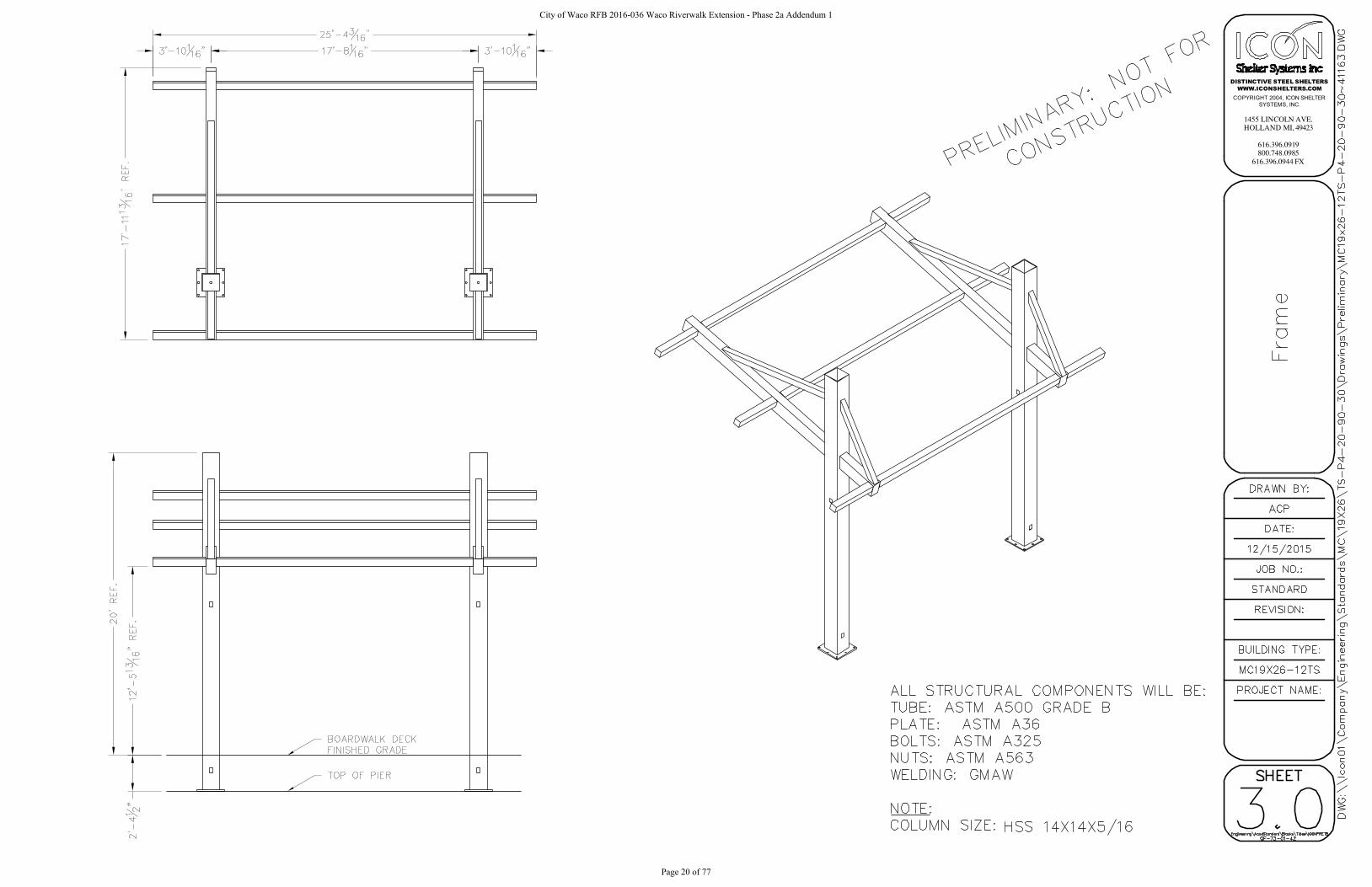
2.3 SHADE STRUCTURE
A. Overlook Shade Structure
1. Acceptable Manufacturer: ICON Shelter Systems, Inc., 1455 Lincoln Rd., Holland, MI,
49423.
Email: [email protected], Website: www.iconshelters.com.
2. Pricing for this specific project and specified shelter can be requested from:
1) The Playwell Group
4743 Iberia Avenue
Suite C
Dallas, TX 75207
Ph: 972-488-9355
Fx: 972-488-0642
3. Model No.: MC19x26-12TS –refer to manufacturer specifications (attached to end of this
specification)
4. Finish (Frames/Columns): Surrey Beige
5. Finish (Roof): Slate Grey
6. Color (Columns): Surrey Beige with veneer (see column veneer specification)
7. Color (Roof): Slate Grey
8. Anchor: anchor per manufacturer’s recommendations.
2.4 MATERIALS
A. Refer to manufacturers specifications for all required materials.
City of Waco RFB 2016-036 Waco Riverwalk Extension - Phase 2a Addendum 1
Page 25 of 77

Waco Riverwalk Extension (Phase 2A) AVO 29736
Waco Riverwalk Extension (Phase 2a) Site Furnishings
Project No. 29736 April 2016
PART 3 - EXECUTION
3.1 INSTALLATION
A. Comply with manufacturer's written installation instructions unless more stringent requirements
are indicated. Complete field assembly of site furnishings where required.
B. Unless otherwise indicated, install site furnishings after landscaping and paving have been
completed.
C. Install site furnishings level, plumb, true, and securely anchored at locations indicated on
Drawings.
D. Fasteners: Nuts and bolts shall be upset and tack welded to prevent disassembly.
PART 4 - MEASUREMENT
4.1 BENCHES – This item will be measured by the Each.
4.2 TRASH RECEPTACLE - This item will be measured by the Each.
4.3 SHADE STRUCTURE - This item will be measured by the Each.
PART 5 - PAYMENT
5.1 PAYMENT – The work performed and the materials furnished in accordance with the items and
measurements as provided under the “Measurement” section will be paid for at the unit price bid
for the listed site furnishing items in the “Measurement” section. This price is full compensation
for furnishing all mentioned materials (per details and specifications), structural footings,
equipment, anchor systems, labor, tools, and incidentals.
City of Waco RFB 2016-036 Waco Riverwalk Extension - Phase 2a Addendum 1
Page 26 of 77

Waco Riverwalk Extension (Phase 2A) AVO 29736
Waco Riverwalk Extension (Phase 2a) Site Furnishings
Project No. 29736 April 2016
7.301 - SITE FURNISHINGS (ICON SHADE STRUCTURE)
PART 1 - GENERAL
1.01 DESCRIPTION OF PRODUCT
A. Shelter Type: 19’ x 26’ Cantilever Monoslope style shelter with T&G and Standing Seam
roof panels.
B. Roof Slope: 4:12
C. Clear height under Tie Beam (UTB): 12’-0”. This is the clearance under the tie beam which
spans between the columns.
1.02 REFERENCES
A. REFERENCED STANDARDS
1. AISC – American Institute of Steel Construction
a. AISC Steel Construction Manual – 14th edition
b. AISC 360-10 Specification for Structural Steel Buildings
2. ASTM – American Society for Testing and Materials
a. ASTM A36/A36M – Standard Specification for Carbon Structural Steel; 2008
b. ASTM A325 – Standard Specification for Structural Steel Bolts, Heat Treated,
120/105 ksi
Minimum Tensile Strength; 2010
c. ASTM A563 – Standard Specification for Carbon and Alloy Steel Nuts; 2007a
d. ASTM A500 – Standard Specification for Cold-Formed Welded and Seamless Car-
bon Steel
Structural Tubing in Rounds and Shapes; 2010a
e. ASTM A653/A653M – Standard Specification for Sheet Steel, Zinc-Coated (Galva-
nized) or
Zinc-Iron Alloy Coated (Galvanealed) by the Hot Dip Process; 2010
f. ASTM A792/A792M – Standard Specification for Steel Sheet, 55% Aluminum-Zinc
Alloy
Coated by the Hot-Dip Process; 2010
g. ASTM F1554 – Standard Specification for Anchor Bolts, Steel, 36, 50 and 105 ksi
Yield Strength; 2007a
3. AWS – American Welding Society
a. D1.1
b. D1.3
c. D1.8
4. OSHA – Occupational Safety and Health Administration
a. Steel Erection Standard 29 CFR 1926.750 Part R
5. SSPC – Steel Structures Painting Council
a. SSPC-SP 2 – Hand Tool Cleaning; 2004
b. SSPC-SP 10/NACE No. 2 – Near White Blast Cleaning; 2007
6. LEED – Leadership in Energy and Environmental Design
7. ISO – International Organization for Standardization
City of Waco RFB 2016-036 Waco Riverwalk Extension - Phase 2a Addendum 1
Page 27 of 77

Waco Riverwalk Extension (Phase 2A) AVO 29736
Waco Riverwalk Extension (Phase 2a) Site Furnishings
Project No. 29736 April 2016
1.03 SYSTEM DESCRIPTION
A. The structure shall be a pre-engineered package and shall be shipped as a pre-cut (excluding
standing seam roof panels) and pre-fabricated package that shall include the structural fram-
ing members, roof panels, fasteners and roof trim as well as job specific installation instruc-
tions. The structure will be shipped in an un-assembled package for ease of shipment and
minimum shipping charges.
1.04 SUBMITTALS
A. Submit a minimum of four (4) sets of submittal drawings and (2) sets of structural calcula-
tions signed and sealed by a Professional Engineer licensed in the state of Texas.
B. PRODUCT DESIGN REQUIREMENTS:
1. The structure shall meet the following design requirements
a. Building Code: IBC 2012
b. Ground Snow Load: 20 p.s.f.
c. Live Load: 20 p.s.f.
d. Wind Speed:90 m.p.h.
e. Seismic Design Category: D
C. SUBMITTAL REQUIREMENTS
1. Calculations:
a. Design according to the requirements of the national, state or local building codes as
indicated in Section 1.04.B.
b. Calculations shall include all member design for each different member type.
c. Connection design for each different connection that will determine the design of the
bolts, welds, plate thickness and anchorage to the foundation.
d. Foundation design shall be for the loads applied and not a generic foundation design,
taking into account all soils information.
2. Submittal Drawings:
a. Anchor bolt layout with all appropriate dimensions for installation.
b. Site specific foundation design.
c. Isometric as well as elevation and plan views of the farming members along with the
member sizes and locations indicated on the drawings.
d. Connection details for every connection on the frame.
e. Roof panel connections and trim installation details.
f. All accessories on the structure shall have an installation detail as well as connection
details.
D. FOUNDATION DESIGN
1. The foundation design shall be supplied by the manufacturer.
2. Anchor bolts shall be supplied by the manufacturer.
3. Foundation materials and labor shall be provided by the structure contractor.
4. Owner should provide site specific soils information for proper foundation design, if that
data is not provided the foundation will be design for the minimum soil values allowed
by code.
City of Waco RFB 2016-036 Waco Riverwalk Extension - Phase 2a Addendum 1
Page 28 of 77

Waco Riverwalk Extension (Phase 2A) AVO 29736
Waco Riverwalk Extension (Phase 2a) Site Furnishings
Project No. 29736 April 2016
1.05 QUALITY ASSURANCE
A. MANUFACTURER QUALIFICATIONS
1. The product shall be designed, engineered and fabricated at a facility operated and direct-
ly supervised by the manufacturer.
2. The manufacturer shall have a minimum of 9 years in steel shelter fabrication.
3. Full Time on Staff Quality Assurance Manager.
4. All welders must be AWS certified for welding steel structures.
5. Membership in the American Welding Society (AWS).
6. Membership in the American Institute of Steel Construction (AISC).
7. Full Time on Staff Licensed Engineer.
8. Published Quality Control System manual.
9. Quality Control System must pass an annual audit by a Third Part Agency.
10. ISO 9001 certification for Powder Coating System.
B. MANUFACTURER’S CERTIFICATIONS
1. Clark County, NV Approved Fabricator.
2. City of Riverside, CA Approved Fabricator.
3. City of Houston, TX Approved Fabricator Structural Steel.
1.06 FIELD OR SITE CONDITIONS
A. Foundations shall be installed per the ICON installation drawings.
1. All foundations shall be cast at the same elevation unless specifically noted on the ICON
installation drawings.
B. Anchor bolts shall be placed in the foundation as per the ICON installation drawings utilizing
the anchor bolt template supplied with the anchor bolts.
1. Anchor bolts shall be installed per the dimensions and orientation shown on the drawings.
1.07 MANUFACTURER WARRANTY
A. Shelter shall have a 10 year limited warranty on the steel framing members.
B. Shelter shall have a 10 year limited warranty on the powder-coated elements.
C. For all Metal Roofing there will be a pass through warranty direct from the metal Roofing
supplier, warranty shall be provided on request.
2.01 SHELTER SYSTEM AND MATERIALS
A. MANUFACTURERS:
1. Acceptable Manufacturer: ICON Shelter Systems, Inc., 1455 Lincoln Rd., Holland, MI,
49423.
Email: [email protected], Website: www.iconshelters.com.
City of Waco RFB 2016-036 Waco Riverwalk Extension - Phase 2a Addendum 1
Page 29 of 77

Waco Riverwalk Extension (Phase 2A) AVO 29736
Waco Riverwalk Extension (Phase 2a) Site Furnishings
Project No. 29736 April 2016
2. Pricing for this specific project and specified shelter can be requested from:
1) The Playwell Group
4743 Iberia Avenue
Suite C
Dallas, TX 75207 Ph: 972-
488-9355 Fx: 972-488-0642
3. The product shall be designed and fabricated at a facility operated and directly supervised
by the manufacturer.
B. SUBSTITUTION LIMITATIONS:
1. Substitutions must be approved a minimum of ten (10) business days prior to bid. All ap-
proved manufacturers shall be notified on writing before the bid date and shall not be al-
lowed to bid without written notification. Any approval of an alternate manufacturer shall
be through and official bid addendum prior to the bid date.
2. Alternate suppliers shall meet the requirements, qualifications and provide proof of certi-
fications listed under Section 1.05 QUALITY ASSURANCE.
3. Alternate suppliers shall provide documentation that the power-coat system being provid-
ed meets or exceeds the ICON supplied powder-coat system listed under Section
2.01(c)(8).
C. PRODUCT REQUIREMENTS AND MATERIALS:
1. GENERAL:
a. The pre-engineered and pre-fabricated package of parts shall be pre-cut and packaged
unless noted otherwise. These packages will include all parts and pieces necessary to
field assemble the shelter at the jobsite. The shelter shall be shipped in knocked down
format to minimize shipping expenses. Field labor will be kept to a minimum with no
on-site welding required.
2. CONCRETE FOR FOUNDATIONS:
a. Concrete shall have a minimum 28-day compressive strength of 2,500 psi unless not-
ed otherwise on the foundation detail.
b. Reinforcing steel shall be ASTM A615, Grade 60.
3. COLUMNS:
a. Hollow Structural Section (HSS) columns shall meet ASTM A500, Grade B with a
minimum wall thickness of 3/16” (0.1875”).
b. Unless the columns are direct buried in the foundation the columns shall attach to the
foundation with a minimum of four (4) anchor rods and shall meet OSHA Steel Erec-
tion Standard 29 CFR 1926.755(a)(1).
4. STRUCTURAL FRAMING:
a. All Hollow Structural Sections (HSS) shall meet ASTM A500, Grade B. “I” Beams,
tapered columns or open channel sections shall not be accepted for primary members.
5. COMPRESSION RINGS:
a. Compression rings shall be made of ASTM A36 structural plate or of structural chan-
nel welded together to form the ring. All connections not requiring compression rings
shall use ASTM A500, Grade B HSS sections for these connections.
6. CONNECTION REQUIREMENTS:
a. Anchor rods shall be ASTM F1554, Grade 36 unless otherwise noted.
City of Waco RFB 2016-036 Waco Riverwalk Extension - Phase 2a Addendum 1
Page 30 of 77
Waco Riverwalk Extension (Phase 2A) AVO 29736
Waco Riverwalk Extension (Phase 2a) Site Furnishings
Project No. 29736 April 2016
b. Structural fasteners shall be ASTM A325 high strength bolts and A563 nuts.
c. All structural fasteners shall be hidden within the framing members whenever possi-
ble.
d. No field welding shall be required to finish the construction of the shelter.
e. Manufacturer shall supply extra fasteners.
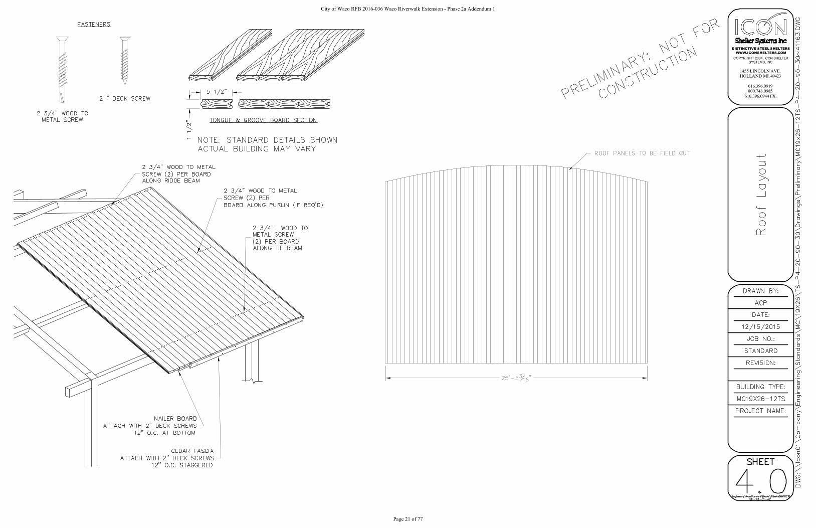
7. ROOFING MATERIALS:
a. PRIMARY ROOF DECK – TONGUE & GROOVE WOOD DECKING
1) Decking shall be 2 x 6 nominal tongue and grooved wood decking.
2) Wood species shall be Western Lodgepole Pine, kiln dried, #2 or better. One
edge V’d and one edge grooved.
3) Fascia shall be Cedar plank.
4) 30# felt shall be supplied when the secondary roofing is supplied by ICON.
b. SECONDARY ROOF DECK – MEDALLION-LOK STANDING SEAM ROOFING
1) Roofing shall be a minimum of 24 gauge Galvalume steel sheet with ribs that are
1 3/4” tall and the panels are 16” wide. Ribs shall run with the slope of the roof
for proper drainage.
2) Roof outside surface shall be a baked on Kynar 500 paint finish and shall be sup-
plied in one of the manufacturer’s standard colors: TBD Ceiling color to be
a “wash coat” primer.
3) All roof panel angles shall be cut in the field.
4) Roofing shall be installed over wood roof deck with 30# felt installed before the
metal roof deck.
5) Metal roofing trim shall match the color of the roof and shall be factory made
from 26 gauge Kynar 500 painted Galvalume sheet steel.
6) Trim includes panel ridge caps, hip caps, eave “J” trim, splice channels, rake
trim, roof peak cap and corner trim as applicable for the model selected. Trim
may need to be field cut to length. Please refer to the installation drawings for
additional information and detail.
7) Ridge, hip and valley caps shall be pre-formed with a single central bend to
match the roof slope and shall be hemmed on both edges.
8) Roof peak caps shall be pre-fabricated with no field assembly required. 9) Roof-
ing is attached to sub-framing with clips.
8. FACTORY FRAME FINISH:
a. All structural steel shall be cleaned, pre-treated and finished in the following manner:
1) The steel shall be shot-blasted to the specification of SSPC-SP10 near white blast
cleaning. SSPC-SP2 hand tool cleaning will not be an acceptable alternative.
2) The shot-blasted parts are then washed with zinc-phosphate in an eight (8) stage
washer.
3) The steel is then immersed in a liquid epoxy and coated through an electro-
deposition process (E-coat), this is coated both inside and out to a uniform cover
of 0.7-0.9 mils. The E-coat totally encapsulates the part for superior corrosion
protection.
4) The parts are then coated with a color coat of TGIC polyester powder and then
one clear coat for a final finish thickness of 8 to 12 mils.
9. FACTORY PRIME PAINT
a. All steel shall be cleaned to the specification of SSPC-SP2 (Hand Tool cleaning) or
better. This removes all loose mill scale, loose rust and any other loose foreign mat-
City of Waco RFB 2016-036 Waco Riverwalk Extension - Phase 2a Addendum 1
Page 31 of 77

Waco Riverwalk Extension (Phase 2A) AVO 29736
Waco Riverwalk Extension (Phase 2a) Site Furnishings
Project No. 29736 April 2016
ter. The clean steel will then be primed with a quick dry, lead and chromate free al-
kyd primer.
10. ACCESSORIES
a. ELECTRICAL ACCESS
1) Standard in all column bases is a 1 3/4" diameter hole, located in the center of the
plate. This allows electrical wiring into the column base.
PART 3 - EXECUTION
3.01 STORAGE AND HANDLING
A. When the shelter arrives at the jobsite protect the products from weather, sunlight and dam-
age.
B. When unloading, pad the forks and use other precautions to protect the powder-coated finish.
Do not use chains to move the materials, use straps. Handle all materials carefully in the field
to avoid scratching the powder-coat finish.
C. Contractor shall store the product elevated from the soil to allow full air circulation around
the materials as do not introduce mold, decay, fungi or insects into or on the materials. One
end of the materials shall be elevated higher than the other end if storage will be longer than a
few days as to allow the water to run off the materials.
3.02 INSTALLATION OF MATERIALS
A. The shelter shall be placed on prepared foundations that were designed by the manufacturer
(unless otherwise noted). Materials for these foundations are not supplied by ICON but by the
foundation installation contractor. Foundation shall be constructed to all local building code
requirements and per good construction practices for the specific site conditions.
1. In accordance with OSHA Steel Erection Standard 29 CFR 1926.750 Part R, anchor rods
shall be installed for proper column stability and shall have a minimum of four (4) anchor
bolts per column. Therefore no single anchor rod column base connections shall be al-
lowed.
B. The contractor shall install all parts and pieces per the manufacturer’s supplied installation in-
structions and these specifications.
C. The interface with other work required is to be coordinated by the customer or the customer’s
agent. Some design may have electrical or plumbing requirements that are not supplied by
ICON.
D. Tolerances on structural steel members are set according to AISC Code of Standard Practice
for Steel Buildings and Bridges and have been used for the fabrication of this product. These
tolerances will not and cannot be increased. No field slotting or opening of holes will be al-
lowed without proper guidance from the ICON Engineering Department.
3.03 REPAIR
City of Waco RFB 2016-036 Waco Riverwalk Extension - Phase 2a Addendum 1
Page 32 of 77

Waco Riverwalk Extension (Phase 2A) AVO 29736
Waco Riverwalk Extension (Phase 2a) Site Furnishings
Project No. 29736 April 2016
A. No field modifications or corrections are allowed without authorization from the ICON Engi-
neering Department.
3.04 SITE QUALITY CONTROL
A. ICON does not require any on-site inspections or testing but these may be required by local
authorities and the local building inspector. Please be aware of any on-site requirements prior
to starting installation.
END OF SECTION
City of Waco RFB 2016-036 Waco Riverwalk Extension - Phase 2a Addendum 1
Page 33 of 77

2000 South 15th Street, Waco, Texas 76706 Ph: 254-235-1048 1200 East FM 2410, Suite B, Harker Heights, Texas 76548 www.LFEctx.com
December 9, 2014
Halff Associates, Inc. Two Sierra Way, Suite 105 Georgetown, Texas 78626-7574
Attention: Shawn Bertram, PE, [email protected]
Reference: Geotechnical Investigation Report Waco Riverwalk Extension Phase 2A Waco, Texas LFE Report W14-050 Halff Associates Project 29736
This letter transmits our report, which has been electronically produced. We appreciate the opportunity to provide geotechnical engineering services for you.
Once the project plans and specifications are completed, we would be pleased to review those portions that pertain to this report. We would also appreciate the chance to provide construction phase services such as materials testing as a part of the success of the project.
If you have any questions regarding our report, please call me at (254) 235-1048.
Respectfully Submitted,
LANGERMAN FOSTER ENGINEERING COMPANY, LLC Texas Registered Engineering Firm No. F-13144
Ottis Foster, P.E. Principal / Geotechnical Engineer
Distribution List:
Halff Associates - Shawn Bertram, PE ([email protected]); Paul Rielly, PE ([email protected]);Randal Endsley ([email protected])
ATTACHMENT 2
City of Waco RFB 2016-036 Waco Riverwalk Extension - Phase 2a Addendum 1
Page 34 of 77

GEOTECHNICAL INVESTIGATION
Waco Riverwalk Extension, Phase 2A
Waco, Texas
LFE Project No. W14-050 December 9, 2014
Report Prepared For: Halff Associates, Inc. C/o Shawn Bertram, PE Georgetown, Texas Report Prepared By:
Ottis Foster, P.E. Principal / Geotechnical Engineer
December 9, 2014
2000 South 15th Street, Waco, Texas 76706 Ph: 254/235-1048 www.LFEctx.com
City of Waco RFB 2016-036 Waco Riverwalk Extension - Phase 2a Addendum 1
Page 35 of 77

Copyright 2014 2000 South 15th Street, Waco, Texas 76706; Ph: 254-235-1048 Page 1 of 18 LFE Project No. W14-050 1200 East FM 2410, Suite B, Harker Heights, Texas 76548; www.LFEctx.com December 9, 2014
GEOTECHNICAL INVESTIGATION WACO RIVERWALK EXTENSION, PHASE 2A
WACO, TEXAS 1.0 INTRODUCTION Project Description: A concrete trail about 2,900 linear feet long is planned, including about
800 linear feet of retaining wall, two bridge structures with lengths of about 250 and 400 linear feet, with the remainder being on-grade. The project is currently in the planning stages and details concerning heights of walls and structural loading conditions are preliminary.
The project vicinity is shown on Plate 1. The scope of services is described in Langerman Foster Engineering (LFE) proposal number GEO14-062, Revision 1, dated July 3, 2014.
Purpose: The purpose of this geotechnical investigation has been to provide
geotechnical design and construction recommendations for the proposed riverwalk extension. These recommendations are based on field investigations, laboratory investigations, and engineering analysis of the investigation results.
2.0 SUBSURFACE EXPLORATION Drilling Date: October 10, 11, and 13 through 19, 2014 (7 days). Dates are shown on
the boring logs. Boring Layout: Boring locations were staked in the field by LFE in coordination with the
Client and with the City of Waco. Nine borings were done at the approximate locations shown on Plate 2.1. Boring GPS coordinates and elevations are shown on Table 2.1. The Wallace Group provided the location and elevation information for Borings 7, 8, and 9, and the others were from a handheld GPS unit. The non-surveyed data is approximate.
City of Waco RFB 2016-036 Waco Riverwalk Extension - Phase 2a Addendum 1
Page 36 of 77

Copyright 2014 2000 South 15th Street, Waco, Texas 76706; Ph: 254-235-1048 Page 2 of 18 LFE Project No. W14-050 1200 East FM 2410, Suite B, Harker Heights, Texas 76548; www.LFEctx.com December 9, 2014
Table 2.1 Approximate Boring Location and Elevation (ft) Boring North West Elev Boring North West Elev
1 31.56092 97.12463 383 6 31.55977 97.12193 391
2 31.56094 97.12350 383 7 31.55937 97.12085 397
3 31.56051 97.12329 382 8 31.55839 97.11998 376
4 31.56014 97.12350 381 9 31.55805 97.11974 376
5 31.55989 97.12320 376 Only borings 7, 8, and 9 were surveyed by a licensed surveyor. The other GPS coordinates were from a hand-held GPS unit.
Sampling and Drilling Operations: A pontoon boat was used to drill borings 5, 8, and 9 on the river. Boring 7
used a truck-mounted drill rig. The other borings used a buggy-mounted rig. Site clearing for boring access was provided by the City of Waco.
The first 3 borings extended 5 feet to provide information for the on-
ground-only portion of the trail. Borings 4 through 9 extended into limestone. In general, Standard Penetration Tests (SPT, ASTM D 1586) were used in clayey and granular soils and rock. Push tubes were used in cohesive soils of Borings 2, 3, and 6. Rock was also cored with a 2-inch inner diameter core barrel, using water or air as drilling fluid. Boring depths and other drilling details are shown on the boring logs in the appendix.
Borings were observed for water while drilling. Water observations could
not be conducted below the depth at which water was used as drilling fluid. Observations are noted on the borings logs and discussed subsequently. Borings were backfilled upon completion.
3.0 LABORATORY TESTS Test Procedures: The following tests were conducted in general conformance with the
standards noted in Table 3.1.
City of Waco RFB 2016-036 Waco Riverwalk Extension - Phase 2a Addendum 1
Page 37 of 77

Copyright 2014 2000 South 15th Street, Waco, Texas 76706; Ph: 254-235-1048 Page 3 of 18 LFE Project No. W14-050 1200 East FM 2410, Suite B, Harker Heights, Texas 76548; www.LFEctx.com December 9, 2014
TABLE 3.1: LABORATORY TESTS
Test Name Test Method
Atterberg Limits ASTM D 4318
-#200 Mesh Sieve ASTM D 1140
Moisture Content ASTM D 2216
Soil Classification ASTM D 2487
Unconfined Compression (rock) ASTM D 2938
Soil samples were not available for compression tests, but were tested using a pocket penetrometer when appropriate.
Test Results: Laboratory test results are tabulated on Plate 3 in the appendix, and on the boring logs. Test results are also discussed subsequently.
4.0 SUBSURFACE MATERIALS Geology: The Geologic Atlas of Texas1 maps the site in the Brazos River as alluvial
deposits, overlying limestone of the Austin Chalk formation. Alluvial Deposits are derived from meandering paths and flood events of the Brazos River. Due to inconsistent deposition, the deposits vary both horizontally and vertically in content and engineering properties. Alluvial deposits are considered recent from a geologic perspective
The underlying Austin Chalk is considered a relatively soft limestone
based on universal rock classification systems, but is considered relatively hard rock in the Central Texas area. Although the Austin Chalk is usually described as limestone, it is comprised of chalk, limestone, and marl (calcareous clay). The unweathered Austin Chalk is gray in color. Weathering produces a tan to white color.
Stratigraphy: Material descriptions are general and range of depths approximate
because boundaries between different strata are seldom clear and abrupt in the field. In general, primarily granular materials with varying amounts of silt and clay were encountered above gray limestone.
1 Virgil E. Barnes, Project Director, Geologic Atlas of Texas, Waco Sheet, The University of Texas at Austin Bureau of Economic Geology, 1970.
City of Waco RFB 2016-036 Waco Riverwalk Extension - Phase 2a Addendum 1
Page 38 of 77

Copyright 2014 2000 South 15th Street, Waco, Texas 76706; Ph: 254-235-1048 Page 4 of 18 LFE Project No. W14-050 1200 East FM 2410, Suite B, Harker Heights, Texas 76548; www.LFEctx.com December 9, 2014
Fill was encountered when the initial Boring 7 was abandoned at about the 10 foot depth due to encountering what appeared to be a concrete obstruction. This boring was moved a few feet away and re-drilled, and the materials did not indicate obvious fill. However, LFE understands that non-engineered fill has been placed at many locations along the Brazos riverbanks in the past, and thus may be encountered for this project.
Gray limestone was encountered at the approximate depths and elevations shown in Table 4.1 for the deeper borings. The depths are from the top of the water for those borings done in water (Borings 5, 8, and 9) or from the top of ground for the borings done on land. Elevation data shown on the logs for borings 1 through 6 were approximated from existing City of Waco topographic maps.
TABLE 4.1 DEPTH TO LIMESTONE (ft)
Boring Depth to
Limestone Limestone Elevation
4 39 342
5 31 345
6 48 ½ 342.5
7 54 ½ 342.5
8 32 344
9 33 343
Differentiating between fill and natural material is especially difficult when the fill is composed of natural soils. More detailed material descriptions are provided on the boring logs in the Appendix. Subsurface water observations are shown on the boring logs and discussed in the following subsection.
Groundwater: Borings 1 through 3 extended 5 feet, and water was not observed in
those borings. Water was observed in Boring 4 about 4 feet below the ground surface, and the water elevation was about equal to the river elevation (elevation 376 ft). Water was observed in Boring 7 about 23 ½ feet below the ground surface, which was also about equal to the river elevation. Boring 6 used water for drilling fluid at about 4 feet, so water observations were not possible below that depth. Boring 6 was at about elevation 391.
City of Waco RFB 2016-036 Waco Riverwalk Extension - Phase 2a Addendum 1
Page 39 of 77
Copyright 2014 2000 South 15th Street, Waco, Texas 76706; Ph: 254-235-1048 Page 5 of 18 LFE Project No. W14-050 1200 East FM 2410, Suite B, Harker Heights, Texas 76548; www.LFEctx.com December 9, 2014
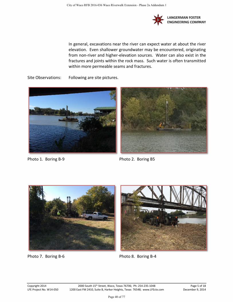
In general, excavations near the river can expect water at about the river elevation. Even shallower groundwater may be encountered, originating from non-river and higher-elevation sources. Water can also exist in the fractures and joints within the rock mass. Such water is often transmitted within more permeable seams and fractures.
Site Observations: Following are site pictures.
Photo 1. Boring B-9
Photo 2. Boring B5
Photo 7. Boring B-6
Photo 8. Boring B-4
City of Waco RFB 2016-036 Waco Riverwalk Extension - Phase 2a Addendum 1
Page 40 of 77

Copyright 2014 2000 South 15th Street, Waco, Texas 76706; Ph: 254-235-1048 Page 6 of 18 LFE Project No. W14-050 1200 East FM 2410, Suite B, Harker Heights, Texas 76548; www.LFEctx.com December 9, 2014
Subsurface Material Characteristics: Soil Movement Potential. Primarily granular materials were
encountered in the borings, and therefore soil movement potential due to expansive clay soils is not a design concern for this project. Some clay is present, but soil movement potential due to expansive soils is expected to be less than about ½ inch. Subsurface Strength Characteristics. The limestone offers the most load support. Unconfined strengths varied from 109 to 269 tsf, with an average strength of 161 tsf. Young’s Modulus varied from 65 to 233 ksi, with an average of 136 ksi. RQD varied from 20 to 92, but the lowest RQDs of 20 and 38 appeared caused by drilling difficulties. An average RQD of about 77% is indicated when accounting for drilling issues. Non-engineered fill has unknown strength characteristics, and is not advised for load support. Non engineered fill was encountered in the first attempt at Boring 7 to about the 10 foot depth, and may have extended deeper. As noted previously, LFE understands that non-engineered fill was placed randomly along the Brazos River in the earlier history of Waco. No unusually weak materials were encountered in the natural materials. Silty soils such as were encountered above the limestone are often difficult for construction operations, and may require special treatment to obtain a suitable working platform or subgrade for load support. This is addressed in the following report sections. Above the limestone, field penetration tests indicated very loose to very dense granular materials, and up to stiff clayey materials. This indicates a significant variation in density and consistency, but is not unexpected by LFE in alluvial deposits.
City of Waco RFB 2016-036 Waco Riverwalk Extension - Phase 2a Addendum 1
Page 41 of 77
Copyright 2014 2000 South 15th Street, Waco, Texas 76706; Ph: 254-235-1048 Page 7 of 18 LFE Project No. W14-050 1200 East FM 2410, Suite B, Harker Heights, Texas 76548; www.LFEctx.com December 9, 2014
5.0 GEOTECHNICAL FOUNDATION RECOMMENDATIONS Project Information: The project consists of a concrete trail with a total length of about 2,900
linear feet. Included are about 800 LF of retaining wall, two bridge structures extending about 250 LF and 400 LF, and with the remainder being on-grade. The project is currently in the planning stages and details concerning heights of walls and structural loading conditions are preliminary.
Structural Loads: Foundation column loads are expected to range from 70 to 250 kips. Expansive Soil: As was discussed in the previous section, less than about ½ inch of
movement potential due to expansive soil activity is anticipated. Pier Design Recommendations: Piers should be designed for vertical support in the limestone, which was
encountered at depths of 31 to 33 feet below the water surface in the borings conducted in the river (Borings 5, 8, and 9). See Table 4.1 for limestone depths and elevations. Lateral load support is discussed in the following section.
Piers must extend at least 5 feet into the gray limestone. These may be
designed for 5000 psf in side shear after 2 feet of penetration into the gray limestone, and for 50,000 psf in end-bearing. These values include a factor of safety of 3 as compared to ultimate capacity.
Local limestone sometimes has softer layers, so piers must be specified to
terminate on a hard layer if end-bearing is used in the design. Lateral load considerations may require a longer pier than needed for vertical loads only, which may result in the vertical loads being handled in side shear without requiring an end-bearing component.
Lateral Loads. Drilled shafts may be designed to resist lateral loads using
the L-Pile parameters provided in Tables 5.1 and 5.2. The values shown are subject to interpretation, and LFE should be contacted if the structural engineer believes the values generate overly (or insufficiently) conservative designs.
City of Waco RFB 2016-036 Waco Riverwalk Extension - Phase 2a Addendum 1
Page 42 of 77

Copyright 2014 2000 South 15th Street, Waco, Texas 76706; Ph: 254-235-1048 Page 8 of 18 LFE Project No. W14-050 1200 East FM 2410, Suite B, Harker Heights, Texas 76548; www.LFEctx.com December 9, 2014
TABLE 5.1: LATERAL LOAD DESIGN PARAMETERS – SOIL MATERIAL
(L-Pile Version 6.0)
Stratum Depth
Below River Bottom, ft
LPile Soil Type
LFE1 Soil Description
Cohesion (psi)
Φ (deg)
E50 (Soils)
Unit Wt2 (pci)
Modulus, k (pci)
1 Scour
depth, or at least 2 ft
Neglect --- --- --- --- --- ---
2 Below scour
depth, to limestone
Sand below water table
Sandy silt, silty sand,
clayey sand, sand, silty gravel, gravel with
sand
none 25 --- 0.034 60
3 11 to 20, (B5 only3)
Stiff Clay below water table
Lean Clay 10.4 --- 0.007 0.034 750
4 20 to
limestone (B5 only)
See Stratum 2
1Langerman Foster Engineering 2Unit weights listed above represent submerged weight 3The structural engineer should run LPile using this stiff clay layer, and without this layer, and use the more conservative result.
City of Waco RFB 2016-036 Waco Riverwalk Extension - Phase 2a Addendum 1
Page 43 of 77

Copyright 2014 2000 South 15th Street, Waco, Texas 76706; Ph: 254-235-1048 Page 9 of 18 LFE Project No. W14-050 1200 East FM 2410, Suite B, Harker Heights, Texas 76548; www.LFEctx.com December 9, 2014
TABLE 5.2: LATERAL LOAD DESIGN PARAMETERS – ROCK MATERIAL
(L-Pile Version 6.0)
Penetrationft
LPile Soil Type
LFE1 Soil Description
Unit Wt2, pci
Initial Mod. of Rock Mass3, psi
Compressive Strength, psi
RQD K_rm4
0 to 25 Weak Rock
Weathered Limestone
0.042 10,000 550 25 % 0.005
> 2 Weak Rock
Weathered Limestone
0.042 30,000 1,600 75 % 0.0005
1Langerman Foster Engineering; 2Unit weights listed above represent total unit weights. 3Determined as the product of the average measured modulus of the rock core strength tests minus 1 standard deviation, times the modulus reduction ratio. 4Obtained from the L-Pile Version 6 manual, which advises typical values from 0.00005 to 0.0005. Average measured values from the laboratory strength tests were on the order of 0.009. 5The strength parameters for this depth interval are 1/3 of the values calculated for the deeper rock shown in the next row to partly account for the less consistent nature of the rock often encountered at the top of the layer. K_rm was reduced by 1/10.
Pier Spacing. For piers spaced horizontally less than 6 diameters center to center, use a reduction factor as shown in Table 5.3.
TABLE 5.3: CLOSELY SPACED PIERS
Pier Spacing Side Friction Reduction Factor (percent)
<2 diameters 50
3 diameters 67
4 diameters 78
5 diameters 89
≥ 6 diameters 100
This table only applies to the reduction in side friction. For end-bearing, the capacity is not reduced if the pier bases are at roughly the same elevation.
Casing. Casing will be required to control groundwater and caving soils.
The contractor should verify the drilling and groundwater conditions prior to starting drilled shaft installation.
City of Waco RFB 2016-036 Waco Riverwalk Extension - Phase 2a Addendum 1
Page 44 of 77

Copyright 2014 2000 South 15th Street, Waco, Texas 76706; Ph: 254-235-1048 Page 10 of 18 LFE Project No. W14-050 1200 East FM 2410, Suite B, Harker Heights, Texas 76548; www.LFEctx.com December 9, 2014
Miscellaneous Geotechnical Parameters
Existing Fill: Existing fill was encountered in the first attempt at Boring 7, and could exist elsewhere on-site. If existing fill is encountered on site, LFE should be retained to evaluate the geotechnical issues raised by the fill on a case-by-case basis. In addition, an environmental professional may be needed to address environmental issues that may be related to the fill. Because fill materials can be similar to native soils, it can be difficult to distinguish between the fill and native material. Therefore, the depths and characteristics of the materials shown on the boring logs are approximations. Improperly compacted, and/or mixed fill materials are subject to random settlement, and significant total and differential settlements of elements supported in the fill can occur. A common remedy for non-engineered fill is to remove and replace such material with select fill, or to re-work the fill if it appears suitable for such action. Be aware that the borings drilled for this investigation were drilled exclusively for geotechnical purposes. LFE does not provide environmental services such as may be warranted for such fill. Other environmental-related investigations by an environmental professional may be warranted.
Seismic: For structural designs based upon the 2012 IBC, the following criteria will
apply. The Site Class is C. The Mapped Spectral Response Acceleration at short periods (SS) is about 0.10g, and the Mapped Spectral Response Acceleration at a 1 second period (S1) is about 0.04g. Site Coefficients are as follows: Fa= 1.2 and Fv= 1.7.
Existing Structures: Vibrations in soils near the water table, especially silty and sandy soils,
can cause strength loss and settlement in the immediate vicinity of the vibrations. Construction operations should minimize vibrations unless the potentially adverse impacts are addressed and acceptable to the impacted parties. Normal construction operations are not expected to cause adverse impacts, but pile driving or using a vibratory roller could be problematic.
City of Waco RFB 2016-036 Waco Riverwalk Extension - Phase 2a Addendum 1
Page 45 of 77

Copyright 2014 2000 South 15th Street, Waco, Texas 76706; Ph: 254-235-1048 Page 11 of 18 LFE Project No. W14-050 1200 East FM 2410, Suite B, Harker Heights, Texas 76548; www.LFEctx.com December 9, 2014
Exercise care in all excavations to avoid undermining existing structures. Sheeting or shoring of excavations should be anticipated, and must be evaluated by an engineer specializing in excavation stability. It is critical that excavations do not cave-in. If drilled shafts are used, particular care must be taken to avoid caving of the soils, which may create collapsible voids.
6.0 RETAINING WALL RECOMMENDATIONS Project Information: LFE understands that a conventional cantilever-type retaining wall less
than about 10 feet in height is planned from about station 14+00 to about 22+00. Figure 6.1 and Table 6.1 provide design recommendations for retaining structures less than about 10 feet in height.
Since the site is on a river, the design engineer must address erosion
issues. Hydrostatic pressure must be included in the lateral load calculations unless such water such as might exist immediately after a flood event can be dissipated prior to imposing its lateral load.
Global Stability: The recommendations contained in Figure 6.1 and Table 6.1 do not
address global stability. Wall cross-sections showing the slopes behind and in front of the wall were not available at report time. It is critical that global stability be checked once these are available.
Footing Embedment Depth: In the absence of global stability issues and assuming erosion or scour
issues are addressed, a one or 2 foot foundation embedment depth is reasonable. Use a deeper embedment if required by code, structural issues, or other considerations.
Tie-Back Anchors In Cut Areas: In select fill, use φ = 30°, c = 250 psf (conservative). In natural soils, use φ
= 20°, c = 250 psf. These are approximate values based on correlations, and LFE should be contacted if the structural engineer believes the values generate overly (or insufficiently) conservative designs.
Foundation Construction: In addition to the following considerations, observe the construction
recommendations provided in Section 7 that are applicable to retaining walls.
City of Waco RFB 2016-036 Waco Riverwalk Extension - Phase 2a Addendum 1
Page 46 of 77

Copyright 2014 2000 South 15th Street, Waco, Texas 76706; Ph: 254-235-1048 Page 12 of 18 LFE Project No. W14-050 1200 East FM 2410, Suite B, Harker Heights, Texas 76548; www.LFEctx.com December 9, 2014
Constructing adjacent to a river may expose softer/weaker soils that were not revealed by the borings and which may not adequately support the foundation for a retaining wall unless firmed up for foundation construction. If such soils are encountered during construction, they must be removed and replaced with select fill, or may be acceptable for re-working to appropriate compaction and moisture content. Another alternative is to use clean crushed stone placed at the base of the excavation to create a working surface. The crushed stone must be clean, not subject to deterioration over time, and should generally range in size from 3 to 6 inches. Such conditions should be analyzed on a case by case basis.
If the option of using clean crushed stone is selected to improve the
subgrade support for the wall foundation, we expect that a layer of about 6 to 12 inches in thickness will be needed, but field conditions will dictate the thickness. Compaction specifications do not apply, except the rock should be placed in such a manner that will stabilize the bottom of the excavation and exhibit adequate support for the footing. This type of clean rock is normally used to stabilize construction entrances, and should be readily available.
Figure 6.1
Wedge ofSelect Fill
For the active condition,movement at the top isabout 0.002X to 0.004XS
X2
3
RH2
RH1
X
For the at-rest condition,it is assumed that nomovement will occur
Synthetic drain ordrainage material
X1
2
City of Waco RFB 2016-036 Waco Riverwalk Extension - Phase 2a Addendum 1
Page 47 of 77

Copyright 2014 2000 South 15th Street, Waco, Texas 76706; Ph: 254-235-1048 Page 13 of 18 LFE Project No. W14-050 1200 East FM 2410, Suite B, Harker Heights, Texas 76548; www.LFEctx.com December 9, 2014
TABLE 6.1: EARTH PRESSURE PARAMETERS
Earth Pressure Coefficient Equivalent Fluid
Pressure (pcf)
Surcharge Pressure, P1
(psf)
Earth Pressure, P2
(psf)
At-Rest (K0) 0.50 60 (0.50)S 60X
Active (KA) 0.33 40 (0.33)S 40X
Passive (KP) 3.0 360 -- --
Values assume a 1H:1V wedge of select fill behind the wall with a unit weight of 120 pcf.
Values assume that the wall is drained. Hydrostatic pressures must be added for an undrained condition
Earth pressure parameters do not include a factor of safety
Drainage material: ASTM C-33, Size 67 gravel aggregate, uniformly compacted
Base sliding resistance: Friction factor tan φ = 0.35. Call for adhesion if additional resistance is desired.
Footing bearing pressure: 2,000 psf
Select backfill cohesion and friction: φ = 30°; c = 250 psf (conservative, will depend largely on % clay)
Resultant Horizontal Forces per linear foot: o RH1= (P1)(X), where RH1 is acting at ½X from the top of the wall o RH2= (0.5)(P2)(X), where RH2 is acting at ⅔X from the top of the wall
7.0 GEOTECHNICAL CONSTRUCTION RECOMMENDATIONS
Site Preparation: Remove at least the existing 6 inches plus any organics, debris, utilities,
underground structures, non-engineered fill or other unsuitable material. The stripping depth must consider field observations with attention given to old drainage areas, uneven topography, and wet soils. The area of removal and replacement should extend at least 2 feet beyond the foundation perimeter.
Proof-roll to detect soft spots or pumping subgrade areas for remediation, and remediate as appropriate. Use a heavy pneumatic tired roller, loaded dump truck, or similar piece of equipment weighing at least 25 tons where practical. After proof-rolling, subgrade soils must also be compacted as required by the following Subgrade Preparation subsection. If the retaining wall footing excavation does not allow such proof-rolling, use other equipment that can demonstrate adequate subgrade support for the retaining wall footing.
City of Waco RFB 2016-036 Waco Riverwalk Extension - Phase 2a Addendum 1
Page 48 of 77

Copyright 2014 2000 South 15th Street, Waco, Texas 76706; Ph: 254-235-1048 Page 14 of 18 LFE Project No. W14-050 1200 East FM 2410, Suite B, Harker Heights, Texas 76548; www.LFEctx.com December 9, 2014
As was discussed previously, construction operations may expose pumping soils that are not easily remediated. If such soils are encountered during construction, they must be removed and replaced with select fill, or may be acceptable for re-working to appropriate compaction and moisture content. Another alternative is to use clean crushed stone placed at the base of the excavation to create a working surface. The crushed stone must be clean, not subject to deterioration over time, and should generally range in size from 3 to 6 inches. Such conditions should be analyzed on a case by case basis.
If the option of using clean crushed stone is selected to improve the
subgrade support for the wall foundation, we expect that a layer of about 6 to 12 inches in thickness will be needed, but field conditions will dictate the thickness. Compaction specifications do not apply, except the rock should be placed in such a manner that will stabilize the bottom of the excavation and exhibit adequate support for the footing. This type of clean rock is normally used to stabilize construction entrances, and should be readily available.
Special care must be observed when removing subsurface structures to make sure that disturbed ground is appropriately compacted to prevent future unwanted settlement. Larger trees recently removed or to be removed are expected to have extensive root systems, and roots greater than about 1 inch in diameter should be removed from areas where decomposition could induce undesirable settlement.
Subgrade Preparation: Scarify and re-compact the exposed subgrade soils to at least 95 percent
of ASTM D698 (or TEX-113-E) maximum dry density at 0 to +3% of the optimum moisture content, based on a 6-inch compacted lift thickness. If not practical for the retaining wall footing, the proof-rolling observations may be acceptable documentation of adequate subgrade preparation, or density tests may be conducted immediately after proof-rolling.
City of Waco RFB 2016-036 Waco Riverwalk Extension - Phase 2a Addendum 1
Page 49 of 77
Copyright 2014 2000 South 15th Street, Waco, Texas 76706; Ph: 254-235-1048 Page 15 of 18 LFE Project No. W14-050 1200 East FM 2410, Suite B, Harker Heights, Texas 76548; www.LFEctx.com December 9, 2014
Select Fill: Fill should meet the requirements of 2004 TxDOT Item 247, Type A, Grade 3 or better. If another local source of select fill is desired, the following specification may be used as a guide:
Maximum Aggregate: 3 inches Percent Retained on #4 Sieve: 25 - 50 Percent Retained on #40 Sieve: 50 - 75 Plasticity Index: 5 - 15 Non-Organic Other locally available non-expansive fill may be acceptable, but should
be evaluated by LFE on a case-by-case basis. Compact the select fill material beneath retaining wall foundations to at least 98% of ASTM D698 (or TEX-113-E) maximum dry density at ±3% of the optimum moisture content. Otherwise, 95% minimum compaction may be used. Specify a maximum compacted lift thickness of six inches, with each lift tested for compliance prior to the addition of subsequent lifts. Observe, monitor, and test the placement and compaction of fill material by LFE on a full-time basis.
Grading: Grading, landscaping, and drainage pose a significant risk factor for future performance of the foundation systems. Preventing water from ponding around the foundation is critical, and good drainage should be obvious to the casual observer. Sprinkler systems must be properly maintained and over-watering of the soils should be avoided.
Vapor Barriers: The structural engineer or architect must determine the need for vapor
barriers, and where to place them. Existing Structures: If new structures will be near or adjacent to existing structures, care must
be exercised in all excavations to avoid undermining the existing building. Sheeting or shoring of excavations should be anticipated, and must be evaluated by an engineer specializing in excavation stability.
Foundations: Foundation construction recommendations are listed below.
1. Follow ACI Manual of Concrete Practice, Item 336 for piers. LFE strongly recommends that the minimum slump requirements specified therein be followed, in part to more easily obtain uniform distribution of the concrete around the reinforcement and against the pier sides than is obtained with lower slumps.
City of Waco RFB 2016-036 Waco Riverwalk Extension - Phase 2a Addendum 1
Page 50 of 77

Copyright 2014 2000 South 15th Street, Waco, Texas 76706; Ph: 254-235-1048 Page 16 of 18 LFE Project No. W14-050 1200 East FM 2410, Suite B, Harker Heights, Texas 76548; www.LFEctx.com December 9, 2014
2. Observe a 24-inch minimum pier shaft diameter to allow for cleaning, minimum construction tolerances, and conventional concrete mix designs. Smaller diameters may be used at the discretion of the structural engineer.
3. LFE must observe the foundation construction to determine that the proper bearing material has been reached in accordance with the recommendations given herein. Bearing depth variations should be expected.
4. Remove water from foundation excavations prior to concrete placement. Prolonged exposure or inundation of the bearing surface with water may result in changes in bearing strength and compressibility characteristics. If delays occur, deepen and clean the drilled shaft excavations to provide a fresh bearing surface.
5. Place concrete promptly after excavations are completed, cleaned, and observed. Place pier concrete before the end of the work day.
6. Design the reinforcement steel cage placed in the shaft to meet at least the following two requirements: (1) the structural requirements for the imposed loads; and (2) stability requirements during the placement of concrete. Other structural or code requirements may also apply.
7. Temporary steel casing will be needed to control groundwater and/or caving soils per ACI 336.1 and ACI 336.3R. Place pier concrete at a minimum 6-inch slump when temporary steel casing is used.
8. Spread footing foundations must be clean, dry, meet the dimension and reinforcement placement requirements provided in the plans and specifications and bear on the recommended bearing material. LFE should be retained to confirm these requirements are met. Concrete should be placed the same day that LFE notes general compliance, and LFE should conduct additional observations if concrete is placed a different day or if the footing conditions materially change following the observations.
City of Waco RFB 2016-036 Waco Riverwalk Extension - Phase 2a Addendum 1
Page 51 of 77
Copyright 2014 2000 South 15th Street, Waco, Texas 76706; Ph: 254-235-1048 Page 17 of 18 LFE Project No. W14-050 1200 East FM 2410, Suite B, Harker Heights, Texas 76548; www.LFEctx.com December 9, 2014
8.0 DESIGN REVIEW AND LIMITATIONS Design Review: The recommendations contained in this report were based on
preliminary site plans and design information provided by the Client. Our recommendations may not be applicable if changes have been made to the original information that formed the basis for this report, and we must be retained to make such a determination if such changes have been made. We also must be given the opportunity to review construction documents to affirm that our recommendations have been interpreted correctly. We cannot be responsible for misinterpretations if not given the opportunity to review aspects of the project that are based on the contents of this report. Such a review is considered an additional service.
Limitations: This report has been prepared for the exclusive use of our client and their
designated project design team. Preparation of the report has been performed using that degree of care and skill ordinarily exercised under similar conditions by reputable geotechnical engineers in the same locality. No warranties, express or implied, are intended or made.
As stated in the attachment titled ‘Important Information About Your Geotechnical Engineering Report,” the subsurface conditions are interpreted from samples taken only at the boring locations. During construction, variations will be encountered, and will require interpretation by LFE to verify the adequacy of the geotechnical recommendations. Other limitations and considerations are discussed in the attachment and are a part of this report.
LFE does not provide environmental services, and this investigation did
not include environmental testing or evaluation. LFE does not know whether environmental services may be appropriate or required for this project. An environmental professional should be retained to evaluate whether such services are appropriate and/or necessary, and to provide such services when so deemed.
City of Waco RFB 2016-036 Waco Riverwalk Extension - Phase 2a Addendum 1
Page 52 of 77

Copyright 2014 2000 South 15th Street, Waco, Texas 76706; Ph: 254-235-1048 Page 18 of 18 LFE Project No. W14-050 1200 East FM 2410, Suite B, Harker Heights, Texas 76548; www.LFEctx.com December 9, 2014
9.0 APPENDIX
Site Location Map Boring Location Sketch Laboratory Test Results Explanation of Boring Log Symbols and Terms Boring Logs
Important Information About Your Geotechnical Engineering Report
City of Waco RFB 2016-036 Waco Riverwalk Extension - Phase 2a Addendum 1
Page 53 of 77

SITE LOCATION MAP
WACO RIVERWALK EXTENSION, PHASE 2A WACO, TEXAS
LFE PROJECT NO. W14-050
PLATE
1
Riverwalk Extension
City of Waco RFB 2016-036 Waco Riverwalk Extension - Phase 2a Addendum 1
Page 54 of 77

BORING LOCATION SKETCH
WACO RIVERWALK EXTENSION, PHASE 2A WACO, TEXAS
LFE PROJECT NO. W14-050
PLATE
2
B – 1
B – 2
B – 3
B – 5
B – 6
B – 4
B – 9
B – 7
B – 8
B – 1
B – 2
City of Waco RFB 2016-036 Waco Riverwalk Extension - Phase 2a Addendum 1
Page 55 of 77

B-1 0.5 - 2.0 20 16 4 51 8
B-1 2.0 - 3.5 25 5
B-1 3.5 - 5.0 32 17
B-2 0.0 - 2.0 21 16 5 48 11
B-2 2.0 - 3.5 41 9
B-2 3.5 - 5.0 44 16
B-3 0.0 - 2.0 20 16 4 54 13
B-3 2.0 - 4.0 99 20
B-3 4.0 - 5.0 100 27
B-4 0.0 - 1.5 59 16
B-4 2.0 - 3.5 20 25
B-4 4.0 - 5.5 32 27
B-4 6.0 - 7.5 27
B-4 8.0 - 9.5 20 26
B-4 10.0 - 11.5 29
B-4 13.5 - 15.0 54 24
B-4 18.5 - 20.0 21
B-4 23.5 - 25.0 65 31
B-4 28.5 - 30.0 29 16 13 49 27
B-4 33.5 - 35.0 11 11
B-4 38.3 - 39.0 14 12
B-4 39.5 - 126.9 1.9
B-4 41.6 - 175.5 2.2
B-4 44.5 - 147.0 1.7
B-5 7.0 - 8.5 27 16 11 66 40
B-5 9.0 - 10.5 19 16 3 63 34
B-5 11.0 - 12.5 22 26
B-5 13.0 - 14.5 42 26
B-5 15.0 - 16.5 26 29
B-5 18.0 - 19.5 25 17 8 78 33
B-5 23.0 - 24.5 22 15 7 63 28
B-5 28.0 - 29.5 38 16 22 19 20
B-5 32.5 - 166.4 1.6
B-5 37.5 - 198.7 2.1
B-6 0.0 - 2.0 45 17 28 58 17
B-6 2.0 - 4.0 9
B-6 6.0 - 7.5 20 16 4 50 13
B-6 8.0 - 9.5 16 11
B-6 10.0 - 11.5 41 19
B-6 18.0 - 20.0 23 17 6 91 24
B-6 23.0 - 25.0 31 21
B-6 28.5 - 29.5 13 19
Strain atFailure
(%)
LiquidLimit
UnconfinedCompressive
Strength(tsf)
PlasticLimit
PlasticityIndex
Project: Waco Riverwalk Extension-Phase 2A
Project Number: W14-050
Summary of Laboratory Results
Unit DryWeight
(pcf)
MoistureContent
(%)
PercentPassingNo. 200Sieve
SampleDepth
(ft.)
BoringNo.
Plate 3
City of Waco RFB 2016-036 Waco Riverwalk Extension - Phase 2a Addendum 1
Page 56 of 77
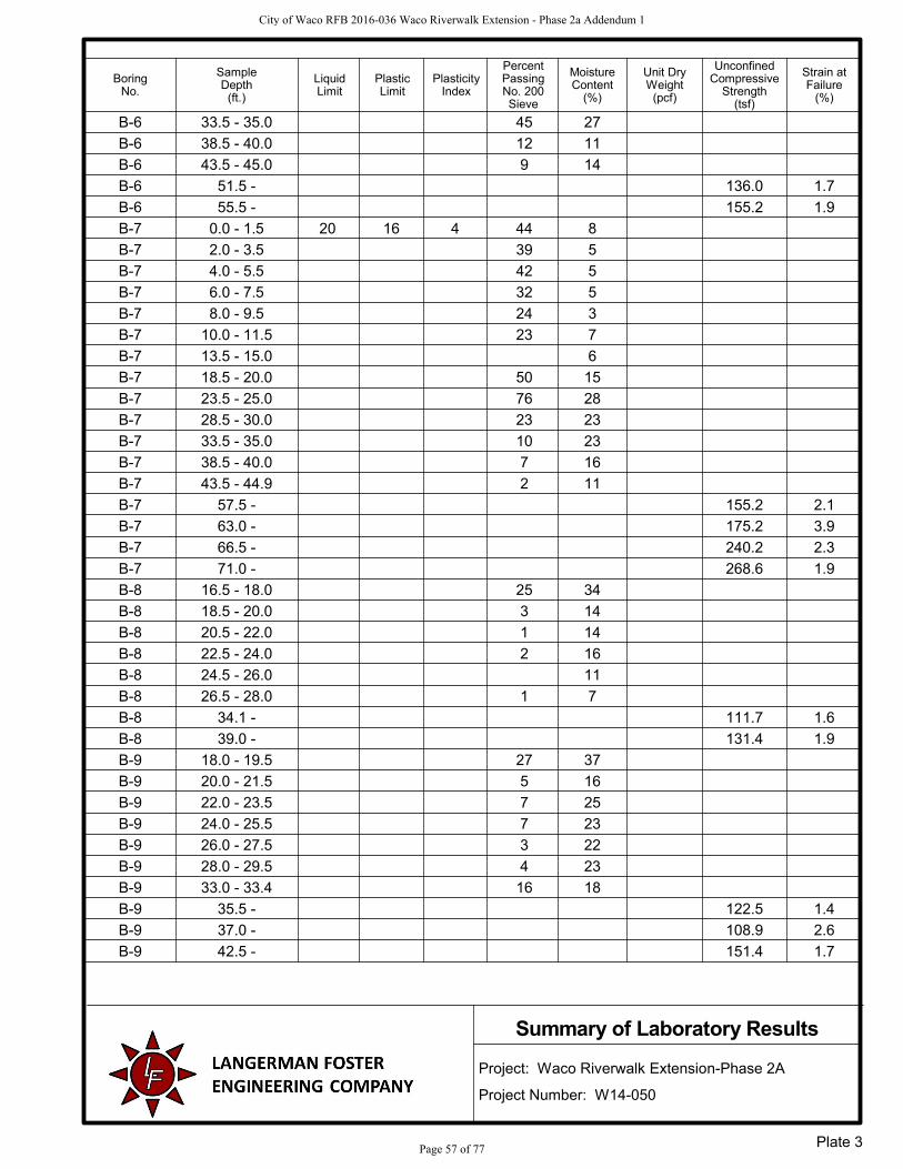
B-6 33.5 - 35.0 45 27
B-6 38.5 - 40.0 12 11
B-6 43.5 - 45.0 9 14
B-6 51.5 - 136.0 1.7
B-6 55.5 - 155.2 1.9
B-7 0.0 - 1.5 20 16 4 44 8
B-7 2.0 - 3.5 39 5
B-7 4.0 - 5.5 42 5
B-7 6.0 - 7.5 32 5
B-7 8.0 - 9.5 24 3
B-7 10.0 - 11.5 23 7
B-7 13.5 - 15.0 6
B-7 18.5 - 20.0 50 15
B-7 23.5 - 25.0 76 28
B-7 28.5 - 30.0 23 23
B-7 33.5 - 35.0 10 23
B-7 38.5 - 40.0 7 16
B-7 43.5 - 44.9 2 11
B-7 57.5 - 155.2 2.1
B-7 63.0 - 175.2 3.9
B-7 66.5 - 240.2 2.3
B-7 71.0 - 268.6 1.9
B-8 16.5 - 18.0 25 34
B-8 18.5 - 20.0 3 14
B-8 20.5 - 22.0 1 14
B-8 22.5 - 24.0 2 16
B-8 24.5 - 26.0 11
B-8 26.5 - 28.0 1 7
B-8 34.1 - 111.7 1.6
B-8 39.0 - 131.4 1.9
B-9 18.0 - 19.5 27 37
B-9 20.0 - 21.5 5 16
B-9 22.0 - 23.5 7 25
B-9 24.0 - 25.5 7 23
B-9 26.0 - 27.5 3 22
B-9 28.0 - 29.5 4 23
B-9 33.0 - 33.4 16 18
B-9 35.5 - 122.5 1.4
B-9 37.0 - 108.9 2.6
B-9 42.5 - 151.4 1.7
Strain atFailure
(%)
LiquidLimit
UnconfinedCompressive
Strength(tsf)
PlasticLimit
PlasticityIndex
Project: Waco Riverwalk Extension-Phase 2A
Project Number: W14-050
Summary of Laboratory Results
Unit DryWeight
(pcf)
MoistureContent
(%)
PercentPassingNo. 200Sieve
SampleDepth
(ft.)
BoringNo.
Plate 3
City of Waco RFB 2016-036 Waco Riverwalk Extension - Phase 2a Addendum 1
Page 57 of 77

CLIENT Halff Associates, Inc.
PROJECT NUMBER W14-050
PROJECT NAME Waco Riverwalk Extension-Phase 2A
PROJECT LOCATION Waco, Texas
ABBREVIATIONSTVPIDUCppm
----
TORVANEPHOTOIONIZATION DETECTORUNCONFINED COMPRESSIONPARTS PER MILLION
LIQUID LIMIT (%)PLASTIC INDEX (%)MOISTURE CONTENT (%)DRY DENSITY (PCF)NON PLASTICPERCENT PASSING NO. 200 SIEVEPOCKET PENETROMETER (TSF)
LLPIWDDNP-200PP
-------
LITHOLOGIC SYMBOLS(Unified Soil Classification System)
CL: USCS Low Plasticity Clay
CL-ML: USCS Low Plasticity Silty Clay
CL-MLS: USCS Low Plasticity Silty Clay& Sand
CLS: USCS Low Plasticity Sandy Clay
GPS: USCS Poorly-graded SandyGravel
LIMESTONE: Limestone
MH: USCS Elastic Silt
MLS: USCS Sandy Silt
SC: USCS Clayey Sand
SM: USCS Silty Sand
SM2: Silty Sand and Gravel
SP: USCS Poorly-graded Sand
SPG2
WATER: WATER
WELL CONSTRUCTION SYMBOLS
KEY TO SYMBOLS
Water Level at TimeDrilling, or as Shown
Water Level After 24Hours, or as Shown
Water Level at End ofDrilling, or as Shown
Auger
Rock Core
Split Spoon
Shelby Tube
SAMPLER SYMBOLS
KE
Y T
O S
YM
BO
LS -
GIN
T S
TD
US
LA
B.G
DT
- 1
2/9
/14
13:
56 -
C:\U
SE
RS
\PU
BLI
C\D
OC
UM
EN
TS
\BE
NT
LEY
\GIN
T\P
RO
JEC
TS
\W14
-050
, W
AC
O R
IVE
RW
ALK
EX
PA
NS
ION
.GP
JLangerman Foster Engineering Company2000 South 15th StreetWaco, Texas 76706Telephone: 254-235-1048
City of Waco RFB 2016-036 Waco Riverwalk Extension - Phase 2a Addendum 1
Page 58 of 77

381.0
378.0
20 16 51
25
32
8
5
17
4
A
SS
SS
SS
SANDY SILT; reddish-brown to tan, with gravel
SILTY SAND; reddish-brown to tan, with varyingclay content
28-18-20(38)
14-10-7(17)
3-2-1(3)
5 ft.
11/11/14
11/11/14
C.RAST
DR
Y U
NIT
WT
.(p
cf)
ATTERBERGLIMITS
Remarks:
Completion Depth:Date Started:Completed:Logged by:
Approximate Surface Elevation 383 feet
Boring was advanced to a depth of 5 feet using dry drilling techniques.Groundwater was not observed above that depth.
ST
RA
IN A
TF
AIL
UR
E (
%)
UN
CO
NF
INE
DC
OM
PR
ES
SIV
ES
TR
EN
GT
H (
tsf)
GR
AP
HIC
LOG
DE
PT
H(f
t)
0
5
PO
CK
ET
PE
N.
(tsf
)
LIQ
UID
LIM
IT
PLA
ST
ICLI
MIT
FIN
ES
CO
NT
EN
T(%
)
MO
IST
UR
EC
ON
TE
NT
(%
)
PLA
ST
ICIT
YIN
DE
X
SA
MP
LE T
YP
E
MATERIAL DESCRIPTION
RE
CO
VE
RY
%(R
QD
)
BLO
WC
OU
NT
S(N
VA
LUE
)
PAGE 1 OF 1BORING NO. B-1
CLIENT Halff Associates, Inc.
PROJECT NUMBER W14-050
PROJECT NAME Waco Riverwalk Extension-Phase 2A
PROJECT LOCATION Waco, Texas
LAN
GE
RM
AN
FO
ST
ER
- G
INT
ST
D U
S L
AB
.GD
T -
12/
9/1
4 1
3:55
- C
:\US
ER
S\P
UB
LIC
\DO
CU
ME
NT
S\B
EN
TLE
Y\G
INT
\PR
OJE
CT
S\W
14-0
50, W
AC
O R
IVE
RW
ALK
EX
PA
NS
ION
.GP
JLangerman Foster Engineering Company2000 South 15th StreetWaco, Texas 76706Telephone: 254-235-1048
City of Waco RFB 2016-036 Waco Riverwalk Extension - Phase 2a Addendum 1
Page 59 of 77

378.0
3.5 21 16 48
41
44
11
9
16
5ST
SS
SS
SILTY SAND; reddish-brown to tan, with varyingclay content
30-22-26(48)
9-17-25(42)
5 ft.
11/11/14
11/11/14
C.RAST
DR
Y U
NIT
WT
.(p
cf)
ATTERBERGLIMITS
Remarks:
Completion Depth:Date Started:Completed:Logged by:
Approximate Surface Elevation 383 feet
Boring was advanced to a depth of 5 feet using dry drilling techniques.Groundwater was not observed above that depth.
ST
RA
IN A
TF
AIL
UR
E (
%)
UN
CO
NF
INE
DC
OM
PR
ES
SIV
ES
TR
EN
GT
H (
tsf)
GR
AP
HIC
LOG
DE
PT
H(f
t)
0
5
PO
CK
ET
PE
N.
(tsf
)
LIQ
UID
LIM
IT
PLA
ST
ICLI
MIT
FIN
ES
CO
NT
EN
T(%
)
MO
IST
UR
EC
ON
TE
NT
(%
)
PLA
ST
ICIT
YIN
DE
X
SA
MP
LE T
YP
E
MATERIAL DESCRIPTION
RE
CO
VE
RY
%(R
QD
)
BLO
WC
OU
NT
S(N
VA
LUE
)
PAGE 1 OF 1BORING NO. B-2
CLIENT Halff Associates, Inc.
PROJECT NUMBER W14-050
PROJECT NAME Waco Riverwalk Extension-Phase 2A
PROJECT LOCATION Waco, Texas
LAN
GE
RM
AN
FO
ST
ER
- G
INT
ST
D U
S L
AB
.GD
T -
12/
9/1
4 1
3:55
- C
:\US
ER
S\P
UB
LIC
\DO
CU
ME
NT
S\B
EN
TLE
Y\G
INT
\PR
OJE
CT
S\W
14-0
50, W
AC
O R
IVE
RW
ALK
EX
PA
NS
ION
.GP
JLangerman Foster Engineering Company2000 South 15th StreetWaco, Texas 76706Telephone: 254-235-1048
City of Waco RFB 2016-036 Waco Riverwalk Extension - Phase 2a Addendum 1
Page 60 of 77
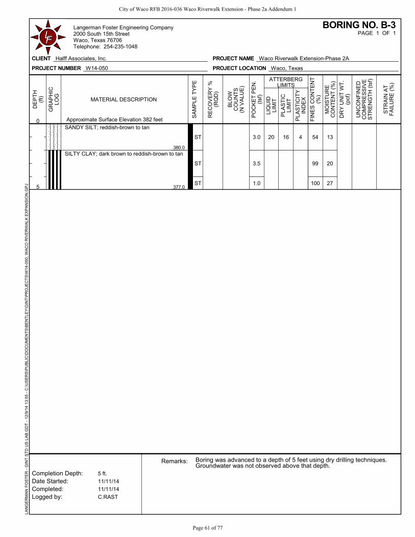
380.0
377.0
3.0
3.5
1.0
20 16 54
99
100
13
20
27
4ST
ST
ST
SANDY SILT; reddish-brown to tan
SILTY CLAY; dark brown to reddish-brown to tan
5 ft.
11/11/14
11/11/14
C.RAST
DR
Y U
NIT
WT
.(p
cf)
ATTERBERGLIMITS
Remarks:
Completion Depth:Date Started:Completed:Logged by:
Approximate Surface Elevation 382 feet
Boring was advanced to a depth of 5 feet using dry drilling techniques.Groundwater was not observed above that depth.
ST
RA
IN A
TF
AIL
UR
E (
%)
UN
CO
NF
INE
DC
OM
PR
ES
SIV
ES
TR
EN
GT
H (
tsf)
GR
AP
HIC
LOG
DE
PT
H(f
t)
0
5
PO
CK
ET
PE
N.
(tsf
)
LIQ
UID
LIM
IT
PLA
ST
ICLI
MIT
FIN
ES
CO
NT
EN
T(%
)
MO
IST
UR
EC
ON
TE
NT
(%
)
PLA
ST
ICIT
YIN
DE
X
SA
MP
LE T
YP
E
MATERIAL DESCRIPTION
RE
CO
VE
RY
%(R
QD
)
BLO
WC
OU
NT
S(N
VA
LUE
)
PAGE 1 OF 1BORING NO. B-3
CLIENT Halff Associates, Inc.
PROJECT NUMBER W14-050
PROJECT NAME Waco Riverwalk Extension-Phase 2A
PROJECT LOCATION Waco, Texas
LAN
GE
RM
AN
FO
ST
ER
- G
INT
ST
D U
S L
AB
.GD
T -
12/
9/1
4 1
3:55
- C
:\US
ER
S\P
UB
LIC
\DO
CU
ME
NT
S\B
EN
TLE
Y\G
INT
\PR
OJE
CT
S\W
14-0
50, W
AC
O R
IVE
RW
ALK
EX
PA
NS
ION
.GP
JLangerman Foster Engineering Company2000 South 15th StreetWaco, Texas 76706Telephone: 254-235-1048
City of Waco RFB 2016-036 Waco Riverwalk Extension - Phase 2a Addendum 1
Page 61 of 77

379.0
368.5
59
20
32
20
54
65
16
25
27
27
26
29
24
21
31
SS
A
SS
A
SS
A
SS
A
SS
A
SS
A
SS
A
SS
A
SS
SANDY SILT; brown to tan, with clay
SILTY SAND; reddish-brown to brown to tan
SANDY SILT; with varying sand content
7-8-9(17)
3-2-2(4)
2-2-2(4)
2-2-1(3)
1-1-1(2)
1-1-2(3)
2-4-12(16)
7-10-12(22)
10-14-20(34)
(Continued Next Page)
48 ft.
11/15/14
11/15/14
HW drilling
DR
Y U
NIT
WT
.(p
cf)
ATTERBERGLIMITS
Remarks:
Completion Depth:Date Started:Completed:Logged by:
Approximate Surface Elevation 381 feet
Boring was advanced to a depth of 11.5 feet before using water in therotary wash drilling process. Groundwater was observed at a depth of 4feet. After a 10 minute observation period, the groundwater levelremained at 4 feet. The observed water level was at about the riverelevation.
ST
RA
IN A
TF
AIL
UR
E (
%)
UN
CO
NF
INE
DC
OM
PR
ES
SIV
ES
TR
EN
GT
H (
tsf)
GR
AP
HIC
LOG
DE
PT
H(f
t)
0
5
10
15
20
25
PO
CK
ET
PE
N.
(tsf
)
LIQ
UID
LIM
IT
PLA
ST
ICLI
MIT
FIN
ES
CO
NT
EN
T(%
)
MO
IST
UR
EC
ON
TE
NT
(%
)
PLA
ST
ICIT
YIN
DE
X
SA
MP
LE T
YP
E
MATERIAL DESCRIPTION
RE
CO
VE
RY
%(R
QD
)
BLO
WC
OU
NT
S(N
VA
LUE
)
PAGE 1 OF 2BORING NO. B-4
CLIENT Halff Associates, Inc.
PROJECT NUMBER W14-050
PROJECT NAME Waco Riverwalk Extension-Phase 2A
PROJECT LOCATION Waco, Texas
LAN
GE
RM
AN
FO
ST
ER
- G
INT
ST
D U
S L
AB
.GD
T -
12/
9/1
4 1
3:55
- C
:\US
ER
S\P
UB
LIC
\DO
CU
ME
NT
S\B
EN
TLE
Y\G
INT
\PR
OJE
CT
S\W
14-0
50, W
AC
O R
IVE
RW
ALK
EX
PA
NS
ION
.GP
JLangerman Foster Engineering Company2000 South 15th StreetWaco, Texas 76706Telephone: 254-235-1048
City of Waco RFB 2016-036 Waco Riverwalk Extension - Phase 2a Addendum 1
Page 62 of 77

352.5
349.0
342.0
333.0
1.9
2.2
1.7
126.9
175.5
147.0
29 16 49
11
14
27
11
12
13
A
SS
A
SS
A
SS
RC
RC
RC
SANDY SILT; with varying sand content(continued)
SILTY SAND; with varying silt content
SAND and GRAVEL
LIMESTONE; gray
90(83)
100(70)
87(43)
1-1-1(2)
20-21-18(39)
21-50/2"
48 ft.
11/15/14
11/15/14
HW drilling
DR
Y U
NIT
WT
.(p
cf)
ATTERBERGLIMITS
Remarks:
Completion Depth:Date Started:Completed:Logged by:
Approximate Surface Elevation 381 feet
Boring was advanced to a depth of 11.5 feet before using water in therotary wash drilling process. Groundwater was observed at a depth of 4feet. After a 10 minute observation period, the groundwater levelremained at 4 feet. The observed water level was at about the riverelevation.
ST
RA
IN A
TF
AIL
UR
E (
%)
UN
CO
NF
INE
DC
OM
PR
ES
SIV
ES
TR
EN
GT
H (
tsf)
GR
AP
HIC
LOG
DE
PT
H(f
t)
25
30
35
40
45
PO
CK
ET
PE
N.
(tsf
)
LIQ
UID
LIM
IT
PLA
ST
ICLI
MIT
FIN
ES
CO
NT
EN
T(%
)
MO
IST
UR
EC
ON
TE
NT
(%
)
PLA
ST
ICIT
YIN
DE
X
SA
MP
LE T
YP
E
MATERIAL DESCRIPTION
RE
CO
VE
RY
%(R
QD
)
BLO
WC
OU
NT
S(N
VA
LUE
)
PAGE 2 OF 2BORING NO. B-4
CLIENT Halff Associates, Inc.
PROJECT NUMBER W14-050
PROJECT NAME Waco Riverwalk Extension-Phase 2A
PROJECT LOCATION Waco, Texas
LAN
GE
RM
AN
FO
ST
ER
- G
INT
ST
D U
S L
AB
.GD
T -
12/
9/1
4 1
3:55
- C
:\US
ER
S\P
UB
LIC
\DO
CU
ME
NT
S\B
EN
TLE
Y\G
INT
\PR
OJE
CT
S\W
14-0
50, W
AC
O R
IVE
RW
ALK
EX
PA
NS
ION
.GP
JLangerman Foster Engineering Company2000 South 15th StreetWaco, Texas 76706Telephone: 254-235-1048
City of Waco RFB 2016-036 Waco Riverwalk Extension - Phase 2a Addendum 1
Page 63 of 77

369.0
367.0
365.0
358.0
27
19
25
22
16
16
17
15
66
63
22
42
26
78
63
40
34
26
26
29
33
28
11
3
8
7
A
SS
A
SS
A
SS
A
SS
A
SS
A
SS
A
SS
WATER
SANDY CLAY; brown to tan
SANDY SILT; brown to tan
SILTY SAND; brown to tan
LEAN CLAY; dark brown to reddish-brown to tan,with varying sand content
1-2-2(4)
4-1-4(5)
3-3-2(5)
6-10-18(28)
11-12-11(23)
5-6-8(14)
7-12-12(24)
(Continued Next Page)
41 ft.
11/14/14
11/14/14
C.Rast/H.W. Drilling
DR
Y U
NIT
WT
.(p
cf)
ATTERBERGLIMITS
Remarks:
Completion Depth:Date Started:Completed:Logged by:
Approximate Surface Elevation 376 feet
Drilling was done underwater. Water was used as a drilling fluid.
ST
RA
IN A
TF
AIL
UR
E (
%)
UN
CO
NF
INE
DC
OM
PR
ES
SIV
ES
TR
EN
GT
H (
tsf)
GR
AP
HIC
LOG
DE
PT
H(f
t)
0
5
10
15
20
25
PO
CK
ET
PE
N.
(tsf
)
LIQ
UID
LIM
IT
PLA
ST
ICLI
MIT
FIN
ES
CO
NT
EN
T(%
)
MO
IST
UR
EC
ON
TE
NT
(%
)
PLA
ST
ICIT
YIN
DE
X
SA
MP
LE T
YP
E
MATERIAL DESCRIPTION
RE
CO
VE
RY
%(R
QD
)
BLO
WC
OU
NT
S(N
VA
LUE
)
PAGE 1 OF 2BORING NO. B-5
CLIENT Halff Associates, Inc.
PROJECT NUMBER W14-050
PROJECT NAME Waco Riverwalk Extension-Phase 2A
PROJECT LOCATION Waco, Texas
LAN
GE
RM
AN
FO
ST
ER
- G
INT
ST
D U
S L
AB
.GD
T -
12/
9/1
4 1
3:55
- C
:\US
ER
S\P
UB
LIC
\DO
CU
ME
NT
S\B
EN
TLE
Y\G
INT
\PR
OJE
CT
S\W
14-0
50, W
AC
O R
IVE
RW
ALK
EX
PA
NS
ION
.GP
JLangerman Foster Engineering Company2000 South 15th StreetWaco, Texas 76706Telephone: 254-235-1048
City of Waco RFB 2016-036 Waco Riverwalk Extension - Phase 2a Addendum 1
Page 64 of 77

349.5
345.0
335.0
1.6
2.1
166.4
198.7
38 16 19 2022
A
SS
A
SSA
RC
RC
LEAN CLAY; dark brown to reddish-brown to tan,with varying sand content (continued)
CLAYEY SAND; brown to tan, with gravel
LIMESTONE; gray
100(92)
90(90)
9-6-15(21)
6-50/3"
41 ft.
11/14/14
11/14/14
C.Rast/H.W. Drilling
DR
Y U
NIT
WT
.(p
cf)
ATTERBERGLIMITS
Remarks:
Completion Depth:Date Started:Completed:Logged by:
Approximate Surface Elevation 376 feet
Drilling was done underwater. Water was used as a drilling fluid.
ST
RA
IN A
TF
AIL
UR
E (
%)
UN
CO
NF
INE
DC
OM
PR
ES
SIV
ES
TR
EN
GT
H (
tsf)
GR
AP
HIC
LOG
DE
PT
H(f
t)
25
30
35
40
PO
CK
ET
PE
N.
(tsf
)
LIQ
UID
LIM
IT
PLA
ST
ICLI
MIT
FIN
ES
CO
NT
EN
T(%
)
MO
IST
UR
EC
ON
TE
NT
(%
)
PLA
ST
ICIT
YIN
DE
X
SA
MP
LE T
YP
E
MATERIAL DESCRIPTION
RE
CO
VE
RY
%(R
QD
)
BLO
WC
OU
NT
S(N
VA
LUE
)
PAGE 2 OF 2BORING NO. B-5
CLIENT Halff Associates, Inc.
PROJECT NUMBER W14-050
PROJECT NAME Waco Riverwalk Extension-Phase 2A
PROJECT LOCATION Waco, Texas
LAN
GE
RM
AN
FO
ST
ER
- G
INT
ST
D U
S L
AB
.GD
T -
12/
9/1
4 1
3:55
- C
:\US
ER
S\P
UB
LIC
\DO
CU
ME
NT
S\B
EN
TLE
Y\G
INT
\PR
OJE
CT
S\W
14-0
50, W
AC
O R
IVE
RW
ALK
EX
PA
NS
ION
.GP
JLangerman Foster Engineering Company2000 South 15th StreetWaco, Texas 76706Telephone: 254-235-1048
City of Waco RFB 2016-036 Waco Riverwalk Extension - Phase 2a Addendum 1
Page 65 of 77
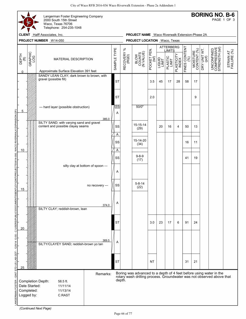
385.0
374.0
369.5
3.5
2.0
3.0
NT
45
20
23
17
16
17
58
50
16
41
91
31
17
9
13
11
19
24
21
28
4
6
ST
ST
SS
A
SS
A
SS
A
SS
A
SS
A
ST
A
ST
SANDY LEAN CLAY; dark brown to brown, withgravel (possible fill)
--- hard layer (possible obstruction)
SILTY SAND; with varying sand and gravelcontent and possible clayey seams
silty clay at bottom of spoon ---
no recovery ---
SILTY CLAY; reddish-brown, lean
SILTY/CLAYEY SAND; reddish-brown yo tan
50/0"
15-15-14(29)
15-14-20(34)
9-8-9(17)
5-8-14(22)
(Continued Next Page)
58.5 ft.
11/11/14
11/13/14
C.RAST
DR
Y U
NIT
WT
.(p
cf)
ATTERBERGLIMITS
Remarks:
Completion Depth:Date Started:Completed:Logged by:
Approximate Surface Elevation 391 feet
Boring was advanced to a depth of 4 feet before using water in therotary wash drilling process. Groundwater was not observed above thatdepth.
ST
RA
IN A
TF
AIL
UR
E (
%)
UN
CO
NF
INE
DC
OM
PR
ES
SIV
ES
TR
EN
GT
H (
tsf)
GR
AP
HIC
LOG
DE
PT
H(f
t)
0
5
10
15
20
25
PO
CK
ET
PE
N.
(tsf
)
LIQ
UID
LIM
IT
PLA
ST
ICLI
MIT
FIN
ES
CO
NT
EN
T(%
)
MO
IST
UR
EC
ON
TE
NT
(%
)
PLA
ST
ICIT
YIN
DE
X
SA
MP
LE T
YP
E
MATERIAL DESCRIPTION
RE
CO
VE
RY
%(R
QD
)
BLO
WC
OU
NT
S(N
VA
LUE
)
PAGE 1 OF 3BORING NO. B-6
CLIENT Halff Associates, Inc.
PROJECT NUMBER W14-050
PROJECT NAME Waco Riverwalk Extension-Phase 2A
PROJECT LOCATION Waco, Texas
LAN
GE
RM
AN
FO
ST
ER
- G
INT
ST
D U
S L
AB
.GD
T -
12/
9/1
4 1
3:55
- C
:\US
ER
S\P
UB
LIC
\DO
CU
ME
NT
S\B
EN
TLE
Y\G
INT
\PR
OJE
CT
S\W
14-0
50, W
AC
O R
IVE
RW
ALK
EX
PA
NS
ION
.GP
JLangerman Foster Engineering Company2000 South 15th StreetWaco, Texas 76706Telephone: 254-235-1048
City of Waco RFB 2016-036 Waco Riverwalk Extension - Phase 2a Addendum 1
Page 66 of 77

354.0
342.5
13
45
12
9
19
27
11
14
A
SS
A
SS
A
SS
A
SS
A
SS
SILTY/CLAYEY SAND; reddish-brown yo tan(continued)
more clayey ---
SAND and GRAVEL; with varying silt and claycontent
LIMESTONE; gray
40-50/6"
10-9-10(19)
20-15-12(27)
12-12-23(35)
50/0"
(Continued Next Page)
58.5 ft.
11/11/14
11/13/14
C.RAST
DR
Y U
NIT
WT
.(p
cf)
ATTERBERGLIMITS
Remarks:
Completion Depth:Date Started:Completed:Logged by:
Approximate Surface Elevation 391 feet
Boring was advanced to a depth of 4 feet before using water in therotary wash drilling process. Groundwater was not observed above thatdepth.
ST
RA
IN A
TF
AIL
UR
E (
%)
UN
CO
NF
INE
DC
OM
PR
ES
SIV
ES
TR
EN
GT
H (
tsf)
GR
AP
HIC
LOG
DE
PT
H(f
t)
25
30
35
40
45
50
PO
CK
ET
PE
N.
(tsf
)
LIQ
UID
LIM
IT
PLA
ST
ICLI
MIT
FIN
ES
CO
NT
EN
T(%
)
MO
IST
UR
EC
ON
TE
NT
(%
)
PLA
ST
ICIT
YIN
DE
X
SA
MP
LE T
YP
E
MATERIAL DESCRIPTION
RE
CO
VE
RY
%(R
QD
)
BLO
WC
OU
NT
S(N
VA
LUE
)
PAGE 2 OF 3BORING NO. B-6
CLIENT Halff Associates, Inc.
PROJECT NUMBER W14-050
PROJECT NAME Waco Riverwalk Extension-Phase 2A
PROJECT LOCATION Waco, Texas
LAN
GE
RM
AN
FO
ST
ER
- G
INT
ST
D U
S L
AB
.GD
T -
12/
9/1
4 1
3:55
- C
:\US
ER
S\P
UB
LIC
\DO
CU
ME
NT
S\B
EN
TLE
Y\G
INT
\PR
OJE
CT
S\W
14-0
50, W
AC
O R
IVE
RW
ALK
EX
PA
NS
ION
.GP
JLangerman Foster Engineering Company2000 South 15th StreetWaco, Texas 76706Telephone: 254-235-1048
City of Waco RFB 2016-036 Waco Riverwalk Extension - Phase 2a Addendum 1
Page 67 of 77

332.5
1.7
1.9
136.0
155.2
RC
RC
LIMESTONE; gray (continued)100(76)
100(80)
58.5 ft.
11/11/14
11/13/14
C.RAST
DR
Y U
NIT
WT
.(p
cf)
ATTERBERGLIMITS
Remarks:
Completion Depth:Date Started:Completed:Logged by:
Approximate Surface Elevation 391 feet
Boring was advanced to a depth of 4 feet before using water in therotary wash drilling process. Groundwater was not observed above thatdepth.
ST
RA
IN A
TF
AIL
UR
E (
%)
UN
CO
NF
INE
DC
OM
PR
ES
SIV
ES
TR
EN
GT
H (
tsf)
GR
AP
HIC
LOG
DE
PT
H(f
t)
50
55
PO
CK
ET
PE
N.
(tsf
)
LIQ
UID
LIM
IT
PLA
ST
ICLI
MIT
FIN
ES
CO
NT
EN
T(%
)
MO
IST
UR
EC
ON
TE
NT
(%
)
PLA
ST
ICIT
YIN
DE
X
SA
MP
LE T
YP
E
MATERIAL DESCRIPTION
RE
CO
VE
RY
%(R
QD
)
BLO
WC
OU
NT
S(N
VA
LUE
)
PAGE 3 OF 3BORING NO. B-6
CLIENT Halff Associates, Inc.
PROJECT NUMBER W14-050
PROJECT NAME Waco Riverwalk Extension-Phase 2A
PROJECT LOCATION Waco, Texas
LAN
GE
RM
AN
FO
ST
ER
- G
INT
ST
D U
S L
AB
.GD
T -
12/
9/1
4 1
3:55
- C
:\US
ER
S\P
UB
LIC
\DO
CU
ME
NT
S\B
EN
TLE
Y\G
INT
\PR
OJE
CT
S\W
14-0
50, W
AC
O R
IVE
RW
ALK
EX
PA
NS
ION
.GP
JLangerman Foster Engineering Company2000 South 15th StreetWaco, Texas 76706Telephone: 254-235-1048
City of Waco RFB 2016-036 Waco Riverwalk Extension - Phase 2a Addendum 1
Page 68 of 77
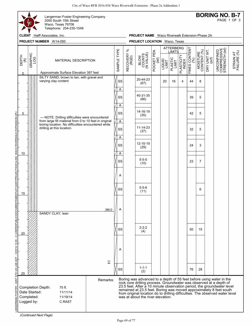
380.0
20 16 44
39
42
32
24
23
50
76
8
5
5
5
3
7
6
15
28
4SS
A
SS
A
SS
A
SS
A
SS
A
SS
A
SS
A
SS
A
SS
SILTY SAND; brown to tan, with gravel andvarying clay content
--- NOTE: Drilling difficulties were encounteredfrom large fill material from 0 to 10 feet in originalboring location. No difficulties encountered whiledrilling at this location.
SANDY CLAY; lean
20-44-23(67)
40-31-35(66)
14-16-19(35)
11-14-23(37)
12-10-19(29)
5-5-5(10)
5-5-6(11)
2-2-2(4)
1-1-1(2)
(Continued Next Page)
75 ft.
11/11/14
11/19/14
C.RAST
DR
Y U
NIT
WT
.(p
cf)
ATTERBERGLIMITS
Remarks:
Completion Depth:Date Started:Completed:Logged by:
Approximate Surface Elevation 397 feet
Boring was advanced to a depth of 55 feet before using water in therock core drilling process. Groundwater was observed at a depth of23.5 feet. After a 10 minute observation period, the groundwater levelremained at 23.5 feet. Boring was moved approximately 8 feet southfrom original location do to drilling difficulties. The observed water levelwas at about the river elevation.
ST
RA
IN A
TF
AIL
UR
E (
%)
UN
CO
NF
INE
DC
OM
PR
ES
SIV
ES
TR
EN
GT
H (
tsf)
GR
AP
HIC
LOG
DE
PT
H(f
t)
0
5
10
15
20
25
PO
CK
ET
PE
N.
(tsf
)
LIQ
UID
LIM
IT
PLA
ST
ICLI
MIT
FIN
ES
CO
NT
EN
T(%
)
MO
IST
UR
EC
ON
TE
NT
(%
)
PLA
ST
ICIT
YIN
DE
X
SA
MP
LE T
YP
E
MATERIAL DESCRIPTION
RE
CO
VE
RY
%(R
QD
)
BLO
WC
OU
NT
S(N
VA
LUE
)
PAGE 1 OF 3BORING NO. B-7
CLIENT Halff Associates, Inc.
PROJECT NUMBER W14-050
PROJECT NAME Waco Riverwalk Extension-Phase 2A
PROJECT LOCATION Waco, Texas
LAN
GE
RM
AN
FO
ST
ER
- G
INT
ST
D U
S L
AB
.GD
T -
12/
9/1
4 1
3:55
- C
:\US
ER
S\P
UB
LIC
\DO
CU
ME
NT
S\B
EN
TLE
Y\G
INT
\PR
OJE
CT
S\W
14-0
50, W
AC
O R
IVE
RW
ALK
EX
PA
NS
ION
.GP
JLangerman Foster Engineering Company2000 South 15th StreetWaco, Texas 76706Telephone: 254-235-1048
City of Waco RFB 2016-036 Waco Riverwalk Extension - Phase 2a Addendum 1
Page 69 of 77

370.0
360.0
355.0
23
10
7
2
23
23
16
11
A
SS
A
SS
A
SS
A
SS
SANDY CLAY; lean (continued)
SILTY SAND
SAND with GRAVEL
SAND and GRAVEL
--- flowing sand, could not sample
1-3-5(8)
3-10-10(20)
4-8-23(31)
10-22-50/4"
(Continued Next Page)
75 ft.
11/11/14
11/19/14
C.RAST
DR
Y U
NIT
WT
.(p
cf)
ATTERBERGLIMITS
Remarks:
Completion Depth:Date Started:Completed:Logged by:
Approximate Surface Elevation 397 feet
Boring was advanced to a depth of 55 feet before using water in therock core drilling process. Groundwater was observed at a depth of23.5 feet. After a 10 minute observation period, the groundwater levelremained at 23.5 feet. Boring was moved approximately 8 feet southfrom original location do to drilling difficulties. The observed water levelwas at about the river elevation.
ST
RA
IN A
TF
AIL
UR
E (
%)
UN
CO
NF
INE
DC
OM
PR
ES
SIV
ES
TR
EN
GT
H (
tsf)
GR
AP
HIC
LOG
DE
PT
H(f
t)
25
30
35
40
45
50
PO
CK
ET
PE
N.
(tsf
)
LIQ
UID
LIM
IT
PLA
ST
ICLI
MIT
FIN
ES
CO
NT
EN
T(%
)
MO
IST
UR
EC
ON
TE
NT
(%
)
PLA
ST
ICIT
YIN
DE
X
SA
MP
LE T
YP
E
MATERIAL DESCRIPTION
RE
CO
VE
RY
%(R
QD
)
BLO
WC
OU
NT
S(N
VA
LUE
)
PAGE 2 OF 3BORING NO. B-7
CLIENT Halff Associates, Inc.
PROJECT NUMBER W14-050
PROJECT NAME Waco Riverwalk Extension-Phase 2A
PROJECT LOCATION Waco, Texas
LAN
GE
RM
AN
FO
ST
ER
- G
INT
ST
D U
S L
AB
.GD
T -
12/
9/1
4 1
3:55
- C
:\US
ER
S\P
UB
LIC
\DO
CU
ME
NT
S\B
EN
TLE
Y\G
INT
\PR
OJE
CT
S\W
14-0
50, W
AC
O R
IVE
RW
ALK
EX
PA
NS
ION
.GP
JLangerman Foster Engineering Company2000 South 15th StreetWaco, Texas 76706Telephone: 254-235-1048
City of Waco RFB 2016-036 Waco Riverwalk Extension - Phase 2a Addendum 1
Page 70 of 77

342.5
322.0
2.1
3.9
2.3
1.9
155.2
175.2
240.2
268.6
A
RC
RC
RC
RC
SAND and GRAVEL (continued)
LIMESTONE; gray
Low RQD likely due to drilling difficulties -----
96(84)
100(92)
96(92)
100(38)
75 ft.
11/11/14
11/19/14
C.RAST
DR
Y U
NIT
WT
.(p
cf)
ATTERBERGLIMITS
Remarks:
Completion Depth:Date Started:Completed:Logged by:
Approximate Surface Elevation 397 feet
Boring was advanced to a depth of 55 feet before using water in therock core drilling process. Groundwater was observed at a depth of23.5 feet. After a 10 minute observation period, the groundwater levelremained at 23.5 feet. Boring was moved approximately 8 feet southfrom original location do to drilling difficulties. The observed water levelwas at about the river elevation.
ST
RA
IN A
TF
AIL
UR
E (
%)
UN
CO
NF
INE
DC
OM
PR
ES
SIV
ES
TR
EN
GT
H (
tsf)
GR
AP
HIC
LOG
DE
PT
H(f
t)
50
55
60
65
70
75
PO
CK
ET
PE
N.
(tsf
)
LIQ
UID
LIM
IT
PLA
ST
ICLI
MIT
FIN
ES
CO
NT
EN
T(%
)
MO
IST
UR
EC
ON
TE
NT
(%
)
PLA
ST
ICIT
YIN
DE
X
SA
MP
LE T
YP
E
MATERIAL DESCRIPTION
RE
CO
VE
RY
%(R
QD
)
BLO
WC
OU
NT
S(N
VA
LUE
)
PAGE 3 OF 3BORING NO. B-7
CLIENT Halff Associates, Inc.
PROJECT NUMBER W14-050
PROJECT NAME Waco Riverwalk Extension-Phase 2A
PROJECT LOCATION Waco, Texas
LAN
GE
RM
AN
FO
ST
ER
- G
INT
ST
D U
S L
AB
.GD
T -
12/
9/1
4 1
3:55
- C
:\US
ER
S\P
UB
LIC
\DO
CU
ME
NT
S\B
EN
TLE
Y\G
INT
\PR
OJE
CT
S\W
14-0
50, W
AC
O R
IVE
RW
ALK
EX
PA
NS
ION
.GP
JLangerman Foster Engineering Company2000 South 15th StreetWaco, Texas 76706Telephone: 254-235-1048
City of Waco RFB 2016-036 Waco Riverwalk Extension - Phase 2a Addendum 1
Page 71 of 77
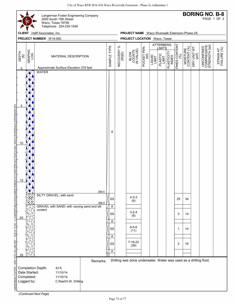
359.5
358.0
25
3
1
2
34
14
14
16
A
SS
A
SS
A
SS
A
SS
A
WATER
SILTY GRAVEL; with sand
GRAVEL with SAND; with varying sand and siltcontent
4-3-3(6)
3-2-4(6)
6-5-6(11)
7-16-23(39)
(Continued Next Page)
42 ft.
11/10/14
11/16/14
C.Rast/H.W. Drilling
DR
Y U
NIT
WT
.(p
cf)
ATTERBERGLIMITS
Remarks:
Completion Depth:Date Started:Completed:Logged by:
Approximate Surface Elevation 376 feet
Drilling was done underwater. Water was used as a drilling fluid.
ST
RA
IN A
TF
AIL
UR
E (
%)
UN
CO
NF
INE
DC
OM
PR
ES
SIV
ES
TR
EN
GT
H (
tsf)
GR
AP
HIC
LOG
DE
PT
H(f
t)
0
5
10
15
20
25
PO
CK
ET
PE
N.
(tsf
)
LIQ
UID
LIM
IT
PLA
ST
ICLI
MIT
FIN
ES
CO
NT
EN
T(%
)
MO
IST
UR
EC
ON
TE
NT
(%
)
PLA
ST
ICIT
YIN
DE
X
SA
MP
LE T
YP
E
MATERIAL DESCRIPTION
RE
CO
VE
RY
%(R
QD
)
BLO
WC
OU
NT
S(N
VA
LUE
)
PAGE 1 OF 2BORING NO. B-8
CLIENT Halff Associates, Inc.
PROJECT NUMBER W14-050
PROJECT NAME Waco Riverwalk Extension-Phase 2A
PROJECT LOCATION Waco, Texas
LAN
GE
RM
AN
FO
ST
ER
- G
INT
ST
D U
S L
AB
.GD
T -
12/
9/1
4 1
3:55
- C
:\US
ER
S\P
UB
LIC
\DO
CU
ME
NT
S\B
EN
TLE
Y\G
INT
\PR
OJE
CT
S\W
14-0
50, W
AC
O R
IVE
RW
ALK
EX
PA
NS
ION
.GP
JLangerman Foster Engineering Company2000 South 15th StreetWaco, Texas 76706Telephone: 254-235-1048
City of Waco RFB 2016-036 Waco Riverwalk Extension - Phase 2a Addendum 1
Page 72 of 77

344.0
334.0
1.6
1.9
111.7
131.4
1
11
7
SS
A
SS
A
RC
RC
GRAVEL with SAND; with varying sand and siltcontent (continued)
LIMESTONE; gray
100(50)
100(62)
17-16-24(40)
8-11-16(27)
42 ft.
11/10/14
11/16/14
C.Rast/H.W. Drilling
DR
Y U
NIT
WT
.(p
cf)
ATTERBERGLIMITS
Remarks:
Completion Depth:Date Started:Completed:Logged by:
Approximate Surface Elevation 376 feet
Drilling was done underwater. Water was used as a drilling fluid.
ST
RA
IN A
TF
AIL
UR
E (
%)
UN
CO
NF
INE
DC
OM
PR
ES
SIV
ES
TR
EN
GT
H (
tsf)
GR
AP
HIC
LOG
DE
PT
H(f
t)
25
30
35
40
PO
CK
ET
PE
N.
(tsf
)
LIQ
UID
LIM
IT
PLA
ST
ICLI
MIT
FIN
ES
CO
NT
EN
T(%
)
MO
IST
UR
EC
ON
TE
NT
(%
)
PLA
ST
ICIT
YIN
DE
X
SA
MP
LE T
YP
E
MATERIAL DESCRIPTION
RE
CO
VE
RY
%(R
QD
)
BLO
WC
OU
NT
S(N
VA
LUE
)
PAGE 2 OF 2BORING NO. B-8
CLIENT Halff Associates, Inc.
PROJECT NUMBER W14-050
PROJECT NAME Waco Riverwalk Extension-Phase 2A
PROJECT LOCATION Waco, Texas
LAN
GE
RM
AN
FO
ST
ER
- G
INT
ST
D U
S L
AB
.GD
T -
12/
9/1
4 1
3:55
- C
:\US
ER
S\P
UB
LIC
\DO
CU
ME
NT
S\B
EN
TLE
Y\G
INT
\PR
OJE
CT
S\W
14-0
50, W
AC
O R
IVE
RW
ALK
EX
PA
NS
ION
.GP
JLangerman Foster Engineering Company2000 South 15th StreetWaco, Texas 76706Telephone: 254-235-1048
City of Waco RFB 2016-036 Waco Riverwalk Extension - Phase 2a Addendum 1
Page 73 of 77

358.5
356.0
27
5
7
7
37
16
25
23
A
SS
A
SS
A
SS
A
SS
WATER
CLAYEY SAND; dark gray, with gravel
SAND; with varying gravel content
2-2-2(4)
5-11-11(22)
2-7-14(21)
3-3-9
(Continued Next Page)
43.5 ft.
11/10/14
11/10/14
C.RAST
DR
Y U
NIT
WT
.(p
cf)
ATTERBERGLIMITS
Remarks:
Completion Depth:Date Started:Completed:Logged by:
Approximate Surface Elevation 376 feet
Drilling was done underwater. Water was used as a drilling fluid.
ST
RA
IN A
TF
AIL
UR
E (
%)
UN
CO
NF
INE
DC
OM
PR
ES
SIV
ES
TR
EN
GT
H (
tsf)
GR
AP
HIC
LOG
DE
PT
H(f
t)
0
5
10
15
20
25
PO
CK
ET
PE
N.
(tsf
)
LIQ
UID
LIM
IT
PLA
ST
ICLI
MIT
FIN
ES
CO
NT
EN
T(%
)
MO
IST
UR
EC
ON
TE
NT
(%
)
PLA
ST
ICIT
YIN
DE
X
SA
MP
LE T
YP
E
MATERIAL DESCRIPTION
RE
CO
VE
RY
%(R
QD
)
BLO
WC
OU
NT
S(N
VA
LUE
)
PAGE 1 OF 2BORING NO. B-9
CLIENT Halff Associates, Inc.
PROJECT NUMBER W14-050
PROJECT NAME Waco Riverwalk Extension-Phase 2A
PROJECT LOCATION Waco, Texas
LAN
GE
RM
AN
FO
ST
ER
- G
INT
ST
D U
S L
AB
.GD
T -
12/
9/1
4 1
3:55
- C
:\US
ER
S\P
UB
LIC
\DO
CU
ME
NT
S\B
EN
TLE
Y\G
INT
\PR
OJE
CT
S\W
14-0
50, W
AC
O R
IVE
RW
ALK
EX
PA
NS
ION
.GP
JLangerman Foster Engineering Company2000 South 15th StreetWaco, Texas 76706Telephone: 254-235-1048
City of Waco RFB 2016-036 Waco Riverwalk Extension - Phase 2a Addendum 1
Page 74 of 77

343.0
332.5
1.4
2.6
1.7
122.5
108.9
151.4
3
4
16
22
23
18
A
SS
A
SS
A
SSA
RC
RC
SAND; with varying gravel content (continued)
LIMESTONE; gray
Low RQD likely due to drilling difficulties -----
88(64)
84(12)
(12)
5-5-6(11)
4-4-7(11)
50/4"
43.5 ft.
11/10/14
11/10/14
C.RAST
DR
Y U
NIT
WT
.(p
cf)
ATTERBERGLIMITS
Remarks:
Completion Depth:Date Started:Completed:Logged by:
Approximate Surface Elevation 376 feet
Drilling was done underwater. Water was used as a drilling fluid.
ST
RA
IN A
TF
AIL
UR
E (
%)
UN
CO
NF
INE
DC
OM
PR
ES
SIV
ES
TR
EN
GT
H (
tsf)
GR
AP
HIC
LOG
DE
PT
H(f
t)
25
30
35
40
PO
CK
ET
PE
N.
(tsf
)
LIQ
UID
LIM
IT
PLA
ST
ICLI
MIT
FIN
ES
CO
NT
EN
T(%
)
MO
IST
UR
EC
ON
TE
NT
(%
)
PLA
ST
ICIT
YIN
DE
X
SA
MP
LE T
YP
E
MATERIAL DESCRIPTION
RE
CO
VE
RY
%(R
QD
)
BLO
WC
OU
NT
S(N
VA
LUE
)
PAGE 2 OF 2BORING NO. B-9
CLIENT Halff Associates, Inc.
PROJECT NUMBER W14-050
PROJECT NAME Waco Riverwalk Extension-Phase 2A
PROJECT LOCATION Waco, Texas
LAN
GE
RM
AN
FO
ST
ER
- G
INT
ST
D U
S L
AB
.GD
T -
12/
9/1
4 1
3:55
- C
:\US
ER
S\P
UB
LIC
\DO
CU
ME
NT
S\B
EN
TLE
Y\G
INT
\PR
OJE
CT
S\W
14-0
50, W
AC
O R
IVE
RW
ALK
EX
PA
NS
ION
.GP
JLangerman Foster Engineering Company2000 South 15th StreetWaco, Texas 76706Telephone: 254-235-1048
City of Waco RFB 2016-036 Waco Riverwalk Extension - Phase 2a Addendum 1
Page 75 of 77

City of Waco RFB 2016-036 Waco Riverwalk Extension - Phase 2a Addendum 1
Page 76 of 77

City of Waco RFB 2016-036 Waco Riverwalk Extension - Phase 2a Addendum 1
Page 77 of 77


