Embed Size (px)
Citation preview
IPC17-XXXGM / IPC17-XXXGTCompactFlash Memory Card
4GB、8GB、16GB、32GB
ADATA Technology Corp.
CompactFlash Memory Card
Datasheet
IPC17-XXXGM / IPC17-XXXGT
4GB、8GB、16GB、32GB
Version 1.0
Document Number: R21-0222
IPC17-XXXGM / IPC17-XXXGTCompactFlash Memory Card
4GB、8GB、16GB、32GB
Revision History
Revision No. History Draft Date Remark Editor
1.0 Jun. 25, 2012 Andy Lin
IPC17-XXXGM / IPC17-XXXGTCompactFlash Memory Card
4GB、8GB、16GB、32GB
Table of Contents 1.0 Product Description........................................................................................................................ 4
1.1 Product Overview .................................................................................................................. 4
2.0 Features .......................................................................................................................................... 4
3.0 Mechanical Specification ............................................................................................................... 5
3.1 Physical dimensions and Weight ............................................................................................ 5
4.0 Electronic Specification ................................................................................................................. 6
4.1 CompactFlash Memory Card Interface Connector ................................................................ 6
4.2 Pin Assignments and Pin Type ............................................................................................... 7
4.3 Function Block Diagram ...................................................................................................... 10
4.4 ECC Descriptions ................................................................................................................. 11
4.5 SMART Command and Data Security................................................................................. 11
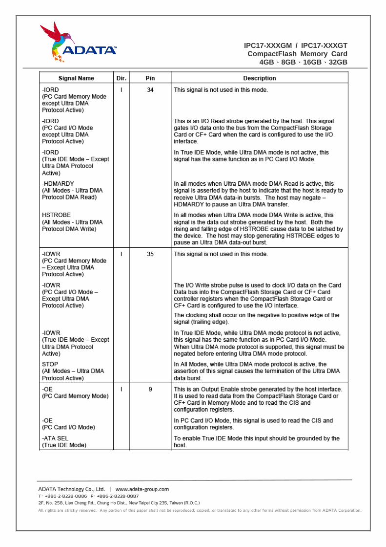
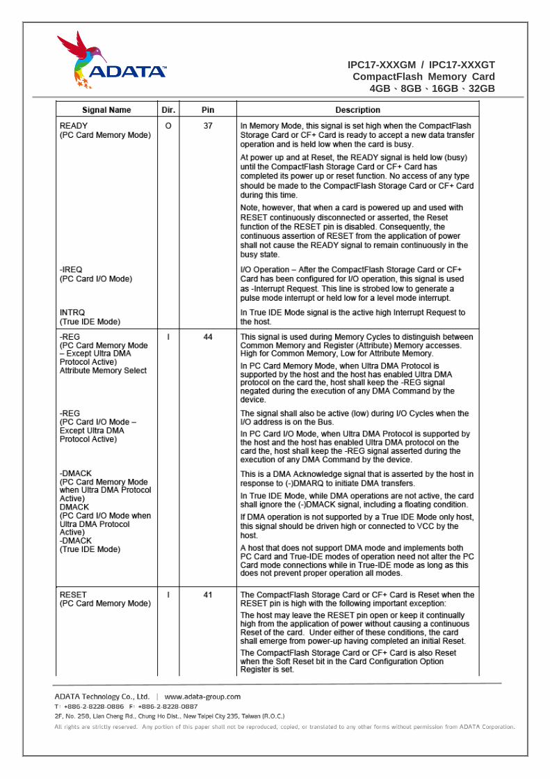
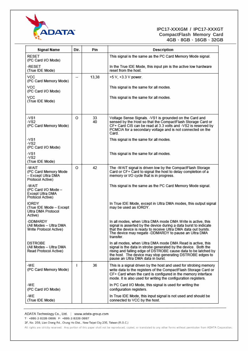
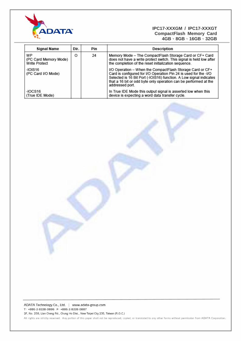
4.6 Signal Description ................................................................................................................ 12
5.0 Product Specifications.................................................................................................................. 19
5.1 System Interface and Configuration .................................................................................... 19
5.2 System Performance ............................................................................................................ 19
5.3 Drive Capacity ..................................................................................................................... 20
5.4 Supply Voltage ..................................................................................................................... 20
5.5 System Power Consumption ................................................................................................ 20
5.6 System Reliability ................................................................................................................ 20
5.7 Environmental Specifications .............................................................................................. 20
5.8 Parameter Setting ................................................................................................................. 21
6.0 AC/DC Characteristics ................................................................................................................. 22
6.1 General DC Characteristics .................................................................................................. 22
6.2 Internal IP Characteristics .................................................................................................... 24
7.0 Ordering Information ................................................................................................................... 26
7.1 Model Name ......................................................................................................................... 26
7.1 Packing ................................................................................................................................. 27
IPC17-XXXGM / IPC17-XXXGTCompactFlash Memory Card
4GB、8GB、16GB、32GB
1.0 Product Description
1.1 Product Overview The ADATA Compact Flash Card TM is an universal low cost data storage and
communication media. It consists of a good compatible and high performance controller
with advanced file management and wear-leverage technology to increase the transfer rate
and life cycle of this solution. It also provides Error Correcting Code (ECC) function to
detect and correct errors automatically. With In System Programming (ISP) function, it is
very easy to load the up-to-date firmware and to solve most of the compatibility issue for
new devices.
2.0 Features
Targeted for portable and stationary applications
Capacity:4GB, 8GB, 16GB, 32GB (0℃~70℃)
32GB (-40℃~85℃)
Conforms to Compact Flash Card specification standard
Fully compatible with PC Card ATA specification
Support for 8-bit or 16-bit host data transfers
Support PIO mode 4 / mode 5 / mode 6
Support UDMA 0~4
Support Error Correcting Code (ECC) function to detect and correct errors.
Support In System Programming (ISP) function to load the firmware.
Supports power down commands and sleep mode
Support Wear Leverage function to maximize data endurance.
+5 Volts or +3.3 Volts operation.
Size:42.8×36.4×3.3 mm
Durability : Minimum 10,000 insertion / removal cycles

IPC17-XXXGM / IPC17-XXXGTCompactFlash Memory Card
4GB、8GB、16GB、32GB
3.0 Mechanical Specification
3.1 Physical dimensions and Weight
Model Height(mm) Width(mm) Length(mm) Weight(gram)
4GB Max 3.3 Max 36.4 Max 42.8 Max 12g
8GB Max 3.3 Max 36.4 Max 42.8 Max 12g
16GB Max 3.3 Max 36.4 Max 42.8 Max 12g
32GB Max 3.3 Max 36.4 Max 42.8 Max 12g
[Figure 3-1] Physical dimension
”All product specifications not covered in this document (electrical performance,
appearance, etc.) are in accordance with ADATA’s defined norms and standards. “
IPC17-XXXGM / IPC17-XXXGTCompactFlash Memory Card
4GB、8GB、16GB、32GB
4.0 Electronic Specification
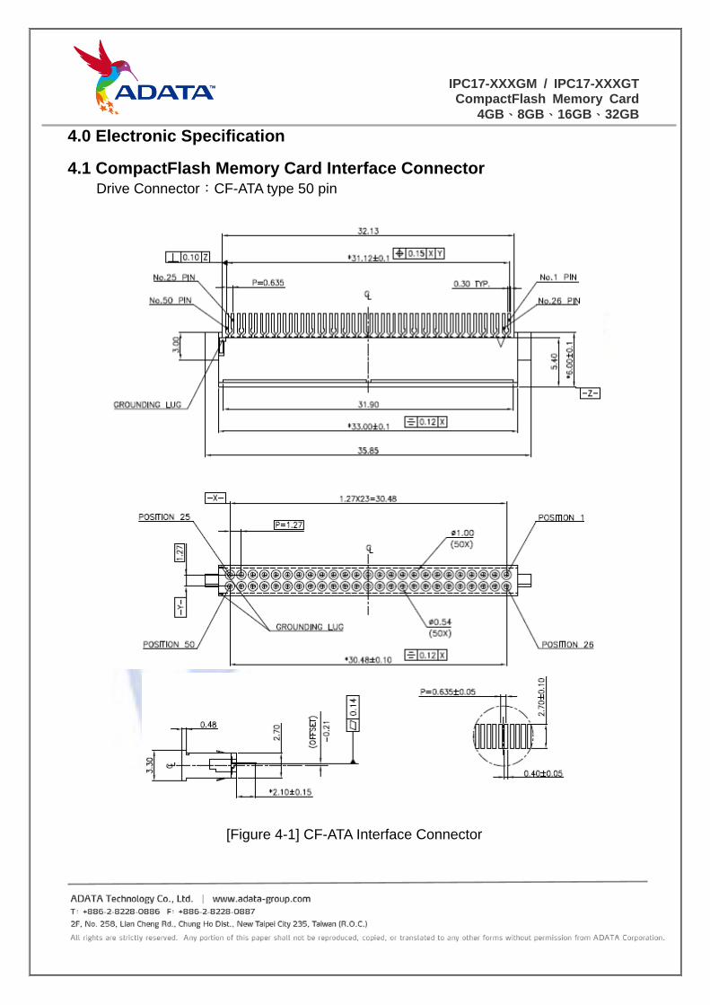
4.1 CompactFlash Memory Card Interface Connector Drive Connector:CF-ATA type 50 pin
[Figure 4-1] CF-ATA Interface Connector
IPC17-XXXGM / IPC17-XXXGTCompactFlash Memory Card
4GB、8GB、16GB、32GB
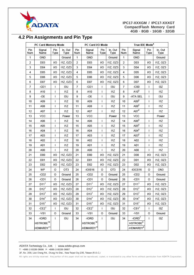
4.2 Pin Assignments and Pin Type
IPC17-XXXGM / IPC17-XXXGTCompactFlash Memory Card
4GB、8GB、16GB、32GB
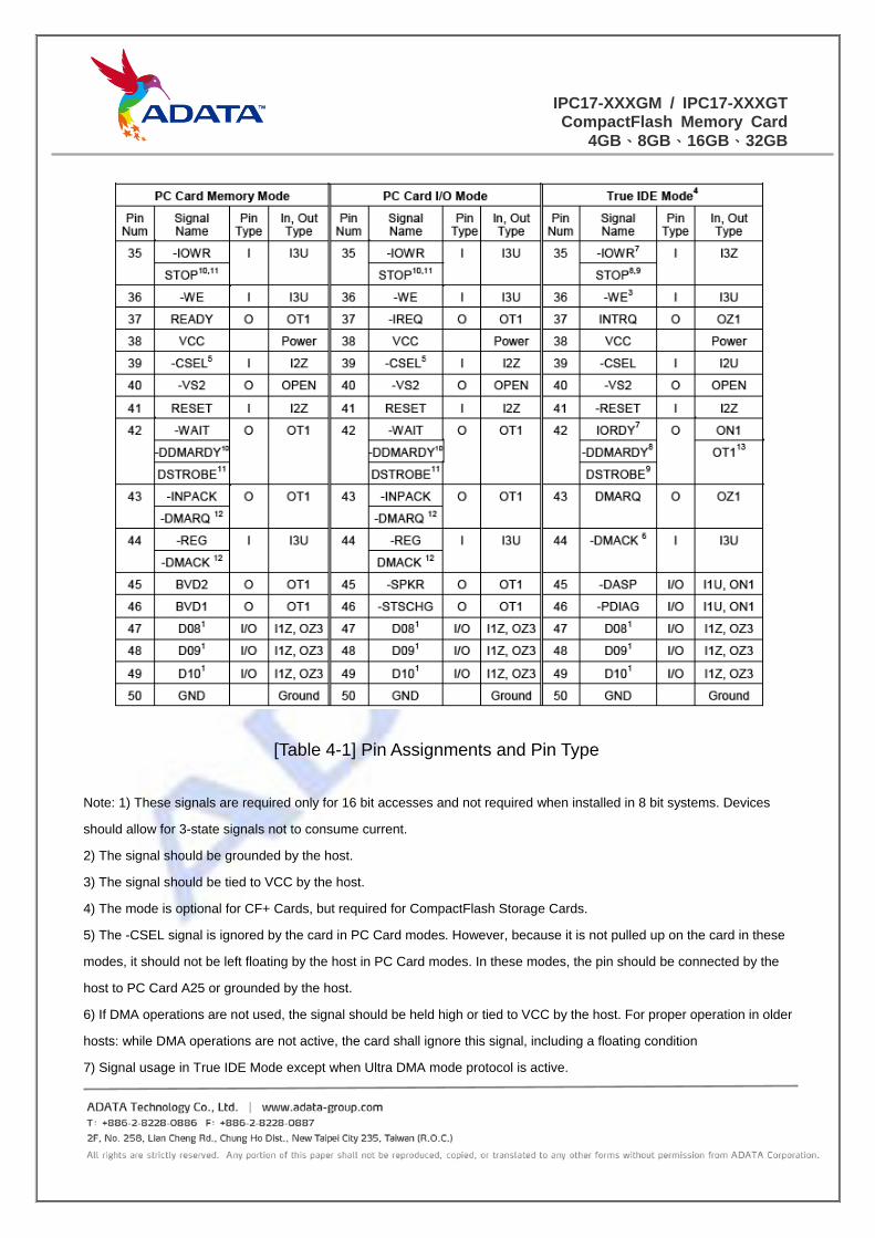
[Table 4-1] Pin Assignments and Pin Type
Note: 1) These signals are required only for 16 bit accesses and not required when installed in 8 bit systems. Devices
should allow for 3-state signals not to consume current.
2) The signal should be grounded by the host.
3) The signal should be tied to VCC by the host.
4) The mode is optional for CF+ Cards, but required for CompactFlash Storage Cards.
5) The -CSEL signal is ignored by the card in PC Card modes. However, because it is not pulled up on the card in these
modes, it should not be left floating by the host in PC Card modes. In these modes, the pin should be connected by the
host to PC Card A25 or grounded by the host.
6) If DMA operations are not used, the signal should be held high or tied to VCC by the host. For proper operation in older
hosts: while DMA operations are not active, the card shall ignore this signal, including a floating condition
7) Signal usage in True IDE Mode except when Ultra DMA mode protocol is active.
IPC17-XXXGM / IPC17-XXXGTCompactFlash Memory Card
4GB、8GB、16GB、32GB
8) Signal usage in True IDE Mode when Ultra DMA mode protocol DMA Write is active.
9) Signal usage in True IDE Mode when Ultra DMA mode protocol DMA Read is active.
10) Signal usage in PC Card I/O and Memory Mode when Ultra DMA mode protocol DMA Write is active.
11) Signal usage in PC Card I/O and Memory Mode when Ultra DMA mode protocol DMA Read is active.
12) Signal usage in PC Card I/O and Memory Mode when Ultra DMA protocol is active.
13) Signal is a totem-pole output during Ultra DMA data bursts in True IDE mode.
IPC17-XXXGM / IPC17-XXXGTCompactFlash Memory Card
4GB、8GB、16GB、32GB
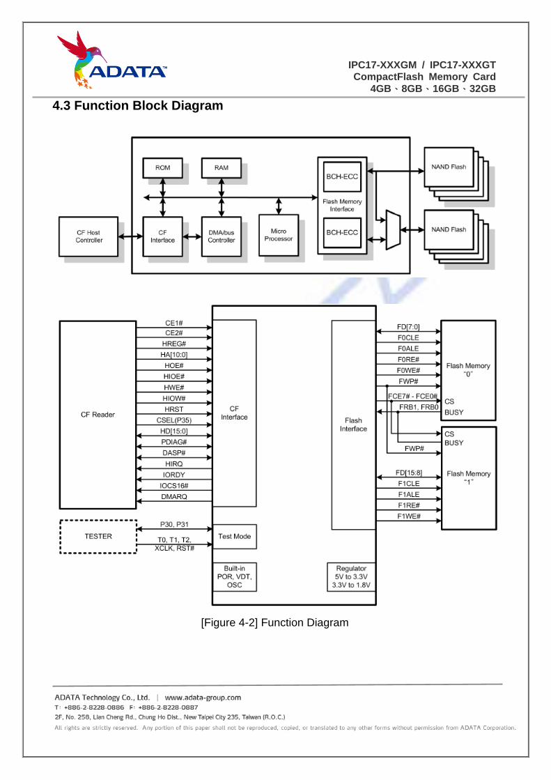
4.3 Function Block Diagram
[Figure 4-2] Function Diagram
IPC17-XXXGM / IPC17-XXXGTCompactFlash Memory Card
4GB、8GB、16GB、32GB
4.4 ECC Descriptions Using 13/24 bit BCH Error Correction Code with each channel, the ADATA
CompactFlash memory card can correct up to 24 random bits in 1,204 bytes. The hardware
executes parity generation and error detection/correction features.
4.5 SMART Command and Data Security The ADATA CompactFlash Memory Card provides SMART command support that
allows users to read spare and bad block information. Users can thus evaluate drive health
at run time and receive an early warning before flash drive lifespan ends. The controller
provides security commands for users to lock and unlock the drive by password or a
hardware switch. The ADATA CompactFlash Memory Card also utilizes some customized
commands to erase blocks for those users who require the highest level of security.
Notably, ADATA can develop different security technologies when requested.
IPC17-XXXGM / IPC17-XXXGTCompactFlash Memory Card
4GB、8GB、16GB、32GB
4.6 Signal Description

IPC17-XXXGM / IPC17-XXXGTCompactFlash Memory Card
4GB、8GB、16GB、32GB
IPC17-XXXGM / IPC17-XXXGTCompactFlash Memory Card
4GB、8GB、16GB、32GB
IPC17-XXXGM / IPC17-XXXGTCompactFlash Memory Card
4GB、8GB、16GB、32GB
IPC17-XXXGM / IPC17-XXXGTCompactFlash Memory Card
4GB、8GB、16GB、32GB
IPC17-XXXGM / IPC17-XXXGTCompactFlash Memory Card
4GB、8GB、16GB、32GB
IPC17-XXXGM / IPC17-XXXGTCompactFlash Memory Card
4GB、8GB、16GB、32GB

IPC17-XXXGM / IPC17-XXXGTCompactFlash Memory Card
4GB、8GB、16GB、32GB
5.0 Product Specifications
5.1 System Interface and Configuration • Supports CompactFlash card specification revision 4.1
• Supports PIO Modes 0, 1, 2, 3, 4, 5 and 6
• Supports Multi-Word DMA Modes 0, 1, 2, 3 and 4
• Supports Ultra DMA Modes 0, 1, 2, 3 and 4
• Supports PCMCIA Extended Memory Mode
• Supports PCMCIA Ultra DMA Modes 0, 1, 2, 3, 4, 5 and 6
5.2 System Performance
The ADATA CompactFlash Memory Card meets the performance requirements listed in
below table.
The performance was measured on a computer system with following setup:
• Platform: ASUS P5K3 Deluxe (Intel P35 + ICH9)
• Operation Systems: Windows XP SP3
• Testing Utility: CrystalDiskMark v3.0
IPC17
Windows OS
CF Mode IDE Mode
CF Mode Read
(Minimum)
CF Mode Write
(Minimum)
IDE Mode Read
(Minimum)
IDE Mode Write
(Minimum)
4GB 15MB/s 4MB/s 20MB/s 5MB/s
8GB 15MB/s 4MB/s 25MB/s 8MB/s
16GB 15MB/s 8MB/s 40MB/s 13MB/s
32GB(GM) 15MB/s 8MB/s 40MB/s 13MB/s
32GB(GT) 15MB/s 8MB/s 40MB/s 13MB/s
Actual performance may vary depending on use conditions and environment
IPC17-XXXGM / IPC17-XXXGTCompactFlash Memory Card
4GB、8GB、16GB、32GB
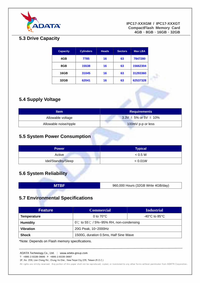
5.3 Drive Capacity
Capacity Cylinders Heads Sectors Max LBA
4GB 7785 16 63 7847280
8GB 15538 16 63 15662304
16GB 31045 16 63 31293360
32GB 62041 16 63 62537328
5.4 Supply Voltage
Item Requirements
Allowable voltage 3.3V ± 5% or 5V ± 10%
Allowable noise/ripple 100mV p-p or less
5.5 System Power Consumption
Power Typical
Active < 0.5 W
Idel/Standby/Sleep < 0.01W
5.6 System Reliability
MTBF 960,000 Hours (32GB Write 4GB/day)
5.7 Environmental Specifications
Feature Commercial Industrial
Temperature 0 to 70°C -40°C to 85°C
Humidity 0℃ to 55℃ / 5%~95% RH, non-condensing
Vibration 20G Peak, 10~2000Hz
Shock 1500G, duration 0.5ms, Half Sine Wave
*Note: Depends on Flash memory specifications.
IPC17-XXXGM / IPC17-XXXGTCompactFlash Memory Card
4GB、8GB、16GB、32GB
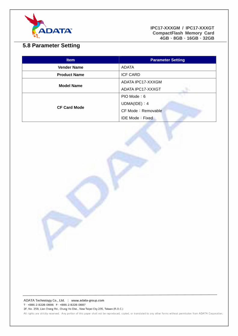
5.8 Parameter Setting
Item Parameter Setting
Vender Name ADATA
Product Name ICF CARD
Model Name ADATA IPC17-XXXGM
ADATA IPC17-XXXGT
CF Card Mode
PIO Mode:6
UDMA(IDE):4
CF Mode:Removable
IDE Mode:Fixed
IPC17-XXXGM / IPC17-XXXGTCompactFlash Memory Card
4GB、8GB、16GB、32GB
6.0 AC/DC Characteristics
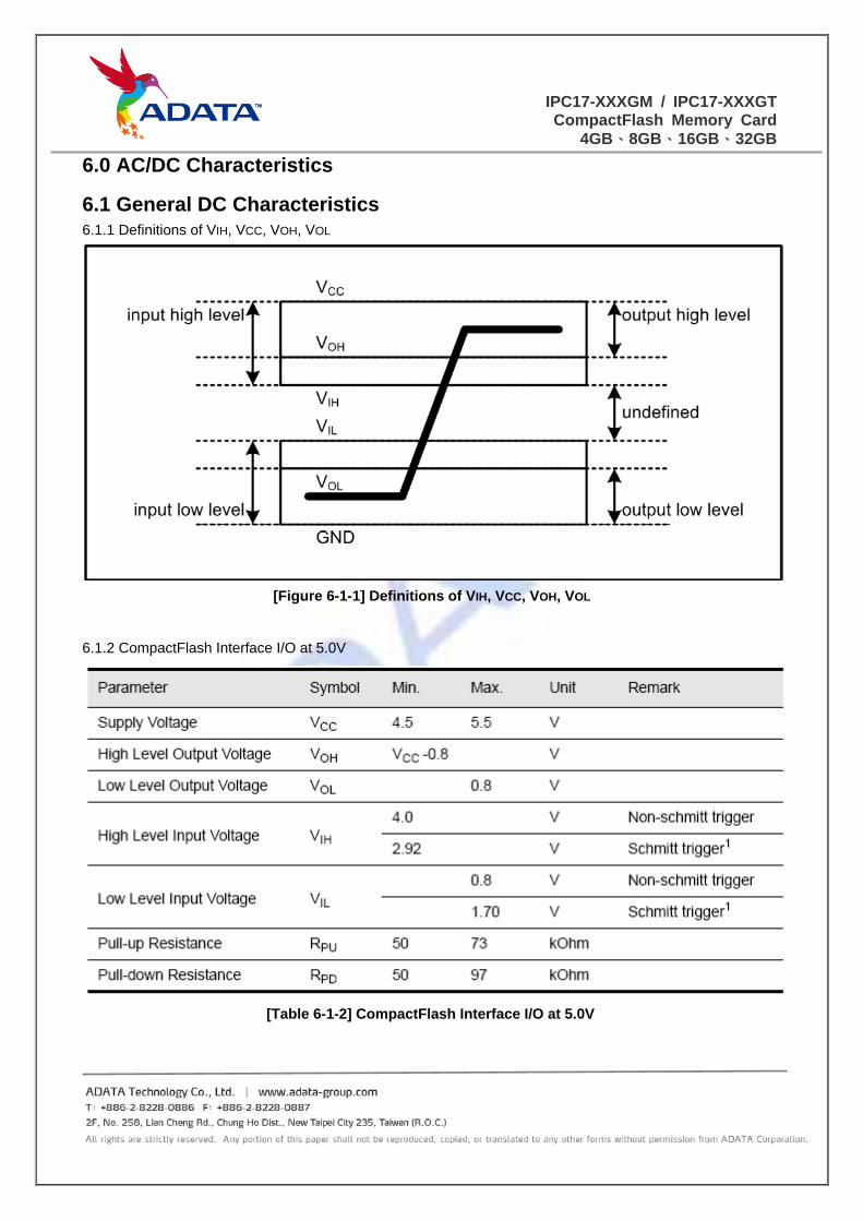
6.1 General DC Characteristics 6.1.1 Definitions of VIH, VCC, VOH, VOL
[Figure 6-1-1] Definitions of VIH, VCC, VOH, VOL
6.1.2 CompactFlash Interface I/O at 5.0V
[Table 6-1-2] CompactFlash Interface I/O at 5.0V
IPC17-XXXGM / IPC17-XXXGTCompactFlash Memory Card
4GB、8GB、16GB、32GB
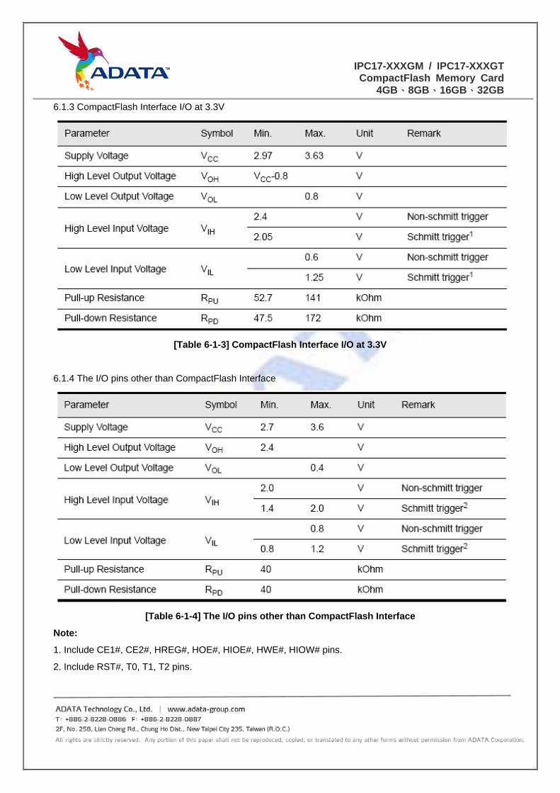
6.1.3 CompactFlash Interface I/O at 3.3V
[Table 6-1-3] CompactFlash Interface I/O at 3.3V
6.1.4 The I/O pins other than CompactFlash Interface
[Table 6-1-4] The I/O pins other than CompactFlash Interface
Note:
1. Include CE1#, CE2#, HREG#, HOE#, HIOE#, HWE#, HIOW# pins.
2. Include RST#, T0, T1, T2 pins.
IPC17-XXXGM / IPC17-XXXGTCompactFlash Memory Card
4GB、8GB、16GB、32GB
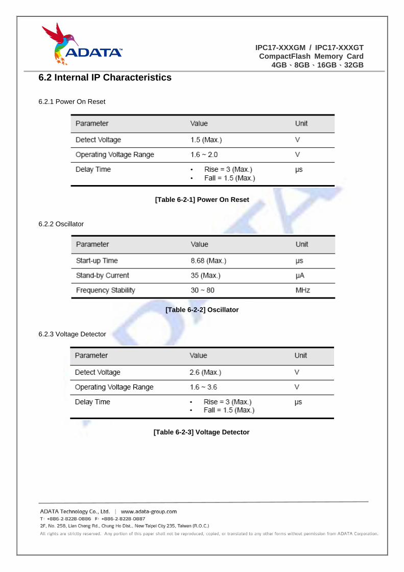
6.2 Internal IP Characteristics
6.2.1 Power On Reset
[Table 6-2-1] Power On Reset
6.2.2 Oscillator
[Table 6-2-2] Oscillator
6.2.3 Voltage Detector
[Table 6-2-3] Voltage Detector
IPC17-XXXGM / IPC17-XXXGTCompactFlash Memory Card
4GB、8GB、16GB、32GB
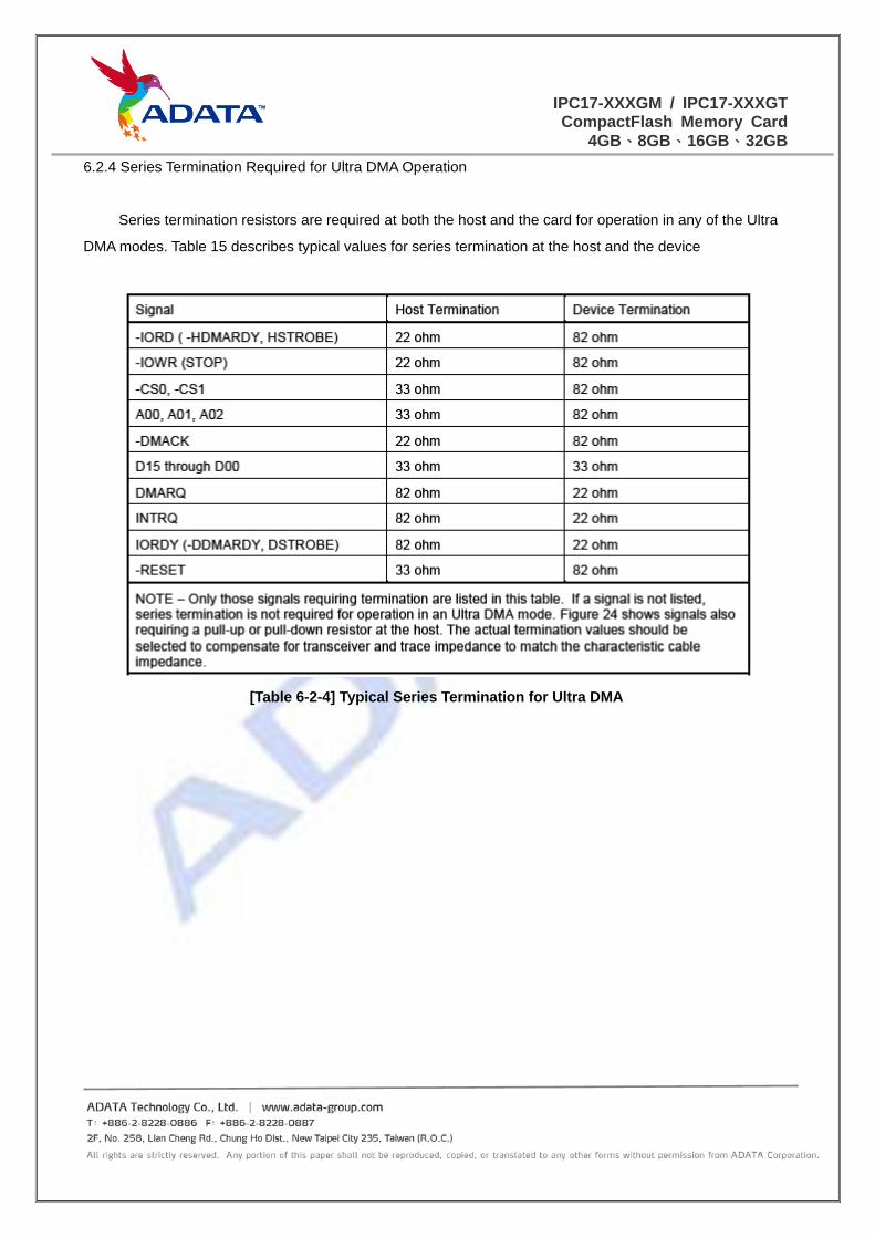
6.2.4 Series Termination Required for Ultra DMA Operation
Series termination resistors are required at both the host and the card for operation in any of the Ultra
DMA modes. Table 15 describes typical values for series termination at the host and the device
[Table 6-2-4] Typical Series Termination for Ultra DMA
IPC17-XXXGM / IPC17-XXXGTCompactFlash Memory Card
4GB、8GB、16GB、32GB
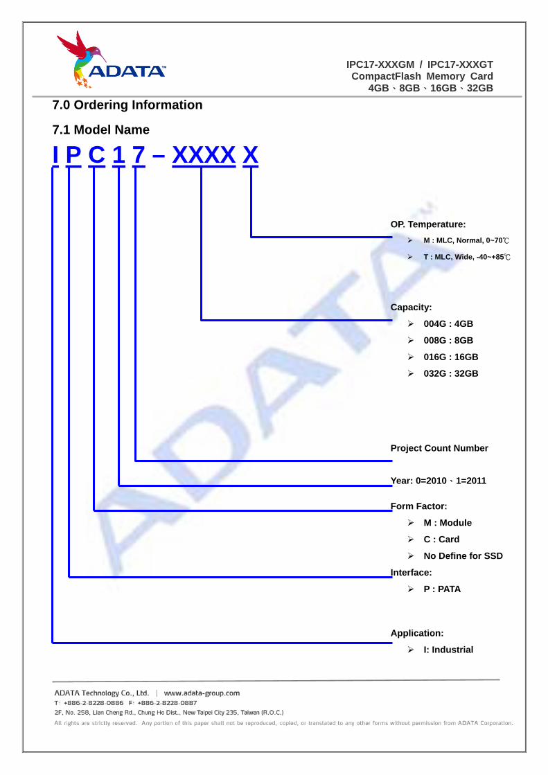
7.0 Ordering Information
7.1 Model Name
I P C 1 7 – XXXX X
OP. Temperature:
M : MLC, Normal, 0~70℃
T : MLC, Wide, -40~+85℃
Capacity:
004G : 4GB
008G : 8GB
016G : 16GB
032G : 32GB
Project Count Number
Year: 0=2010、1=2011
Form Factor:
M : Module
C : Card
No Define for SSD
Interface:
P : PATA
Application:
I: Industrial
IPC17-XXXGM / IPC17-XXXGTCompactFlash Memory Card
4GB、8GB、16GB、32GB
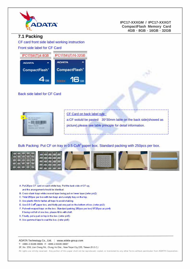
7.1 Packing CF card front side label working instruction
Front side label for CF Card
Back side label for CF Card
Bulk Packing: Put CF on tray in 0.5 Cuft3 paper box. Standard packing with 250pcs per box.
CF Card on back label rule :
a:CF woluld be pasted 35*30mm lable on the back side(showed as
picture),please see lable principle for detail information.
CF卡背標
Back side label for CF card
a
543 62
IPC17-XXXGM / IPC17-XXXGTCompactFlash Memory Card
4GB、8GB、16GB、32GB
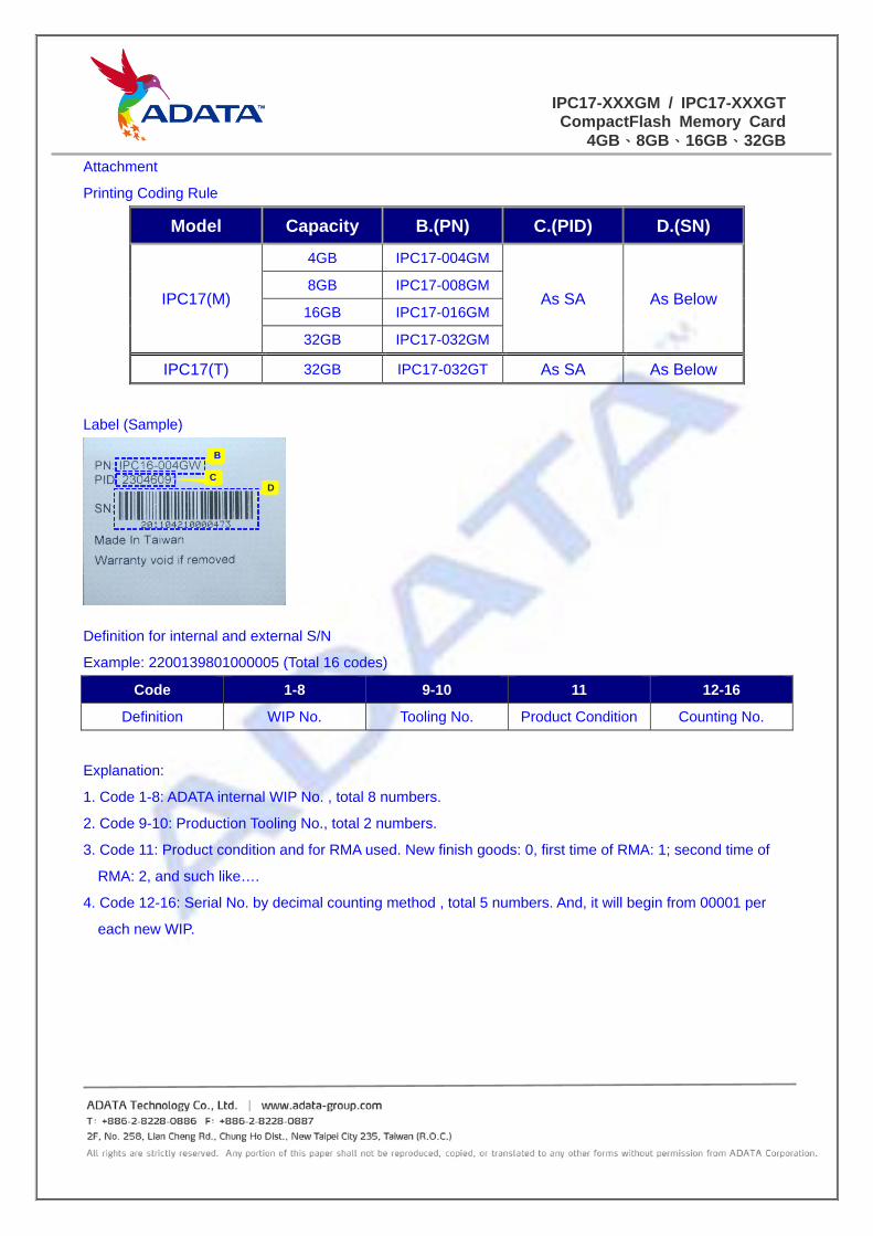
Attachment
Printing Coding Rule
Model Capacity B.(PN) C.(PID) D.(SN)
IPC17(M)
4GB IPC17-004GM
As SA As Below 8GB IPC17-008GM
16GB IPC17-016GM
32GB IPC17-032GM
IPC17(T) 32GB IPC17-032GT As SA As Below
Label (Sample)
Definition for internal and external S/N
Example: 2200139801000005 (Total 16 codes)
Code 1-8 9-10 11 12-16
Definition WIP No. Tooling No. Product Condition Counting No.
Explanation:
1. Code 1-8: ADATA internal WIP No. , total 8 numbers.
2. Code 9-10: Production Tooling No., total 2 numbers.
3. Code 11: Product condition and for RMA used. New finish goods: 0, first time of RMA: 1; second time of
RMA: 2, and such like….
4. Code 12-16: Serial No. by decimal counting method , total 5 numbers. And, it will begin from 00001 per
each new WIP.
B
CD


![Adata-drivenmethodforthestochastic parametrisationofsubgrid … · 2015. 8. 18. · arXiv:1508.03794v1 [physics.ao-ph] 16 Aug 2015 Adata-drivenmethodforthestochastic parametrisationofsubgrid-scaletropicalconvective](https://img.dokumen.tips/doc/110x75/60bbae621a37dd4e1d5004e3/adata-drivenmethodforthestochastic-parametrisationofsubgrid-2015-8-18-arxiv150803794v1.jpg)