Embed Size (px)
Citation preview

Adaptive Management and Administration of ITInfrastructures
Manuel Tiago Azedo Torrinha
Thesis to obtain the Master of Science Degree in
Information Systems and Computer Engineering
Supervisor: Prof. Rui Antonio dos Santos Cruz
Examination Committee
Chairperson: Prof. Luıs Manuel Antunes VeigaSupervisor: Prof. Rui Antonio dos Santos Cruz
Member of the Committee: Prof. Jose Carlos Martins Delgado
October 2017


Acknowledgments
I would like to thank my parents for their friendship, encouragement and caring over all these years,
for always being there for me through thick and thin and without whom this Thesis would not be possible.
I would also like to thank my grandparents, aunts, uncles and cousins for their understanding and support
throughout all these years.
I would also like to acknowledge my dissertation supervisor Prof. Rui Santos Cruz for his insight and
sharing of knowledge that has made this Thesis possible.
A special thanks for my close friend Sergio Almeida for his insight on some of the subjects that
are part of this Thesis and for his cooperation in developing day to day tools that support Systems
Administrators tasks.
Last but not least, to all my friends and colleagues that helped me grow as a person and were always
there for me during the good and bad times in my life.
To each and every one of you – Thank you.


Abstract
With the increased complexity in nowadays Information Technology (IT) environments, as these infras-
tructures become a mix of physical and virtual, where everything connects to the Internet and security
threats propagate almost instantaneously, there is a need to establish models, guides and standards that
support this increase to scale. This thesis addresses different aspects of IT Infrastructure management,
from Logging events to Monitoring performance to Orchestration and Automation of complex operations,
proposing an integration of different tools to work together for managing a complex IT infrastructure
in a more “intelligent” and automated way, through a simplified interface, reducing or eliminating the
repetition of manual operations tasks, in order to prevent common error cases as well as performance
bottlenecks, based, or not, on past occurrences.
Keywords
cloud orchestration, infrastructure automation, resource monitoring, system management, system ad-
ministration, information technology
iii


Resumo
Com o aumento de complexidade em ambientes de Tecnologias de Informacao (TI) actuais, a medida
que estas infraestruturas se transformam num misto de fısico e virtual, onde tudo esta ligado a Internet
e as ameacas a seguranca se propagam de forma quase instantanea, ha a necessidade de estabelecer
modelos, guias e padroes que suportem este crescimento em escala. Esta tese aborda diferentes as-
pectos de gestao de infraestruturas de TI, desde o Registo de eventos a Monitorizacao de performance
ate a Orquestracao e Automacao de operacoes complexas, propondo uma integracao de diferentes fer-
ramentas que trabalham em conjunto para gerir uma complexa infraestrutura de TI de uma forma mais
”inteligente” e automatizada, atraves de uma interface simplificada, reduzindo ou eliminando a repeticao
de tarefas de operacao manuais, por forma a prevenir casos de erros comuns bem como entraves de
performance, baseados, ou nao, em ocorrencias passadas.
Palavras Chave
orquestracao na nuvem, automacao de infraestruturas, monitorizacao de recursos, gestao de sistemas,
administracao de sistemas, tecnologias de informacao
v


Contents
1 Introduction 1
1.1 Motivation . . . . . . . . . . . . . . . . . . . . . . . . . . . . . . . . . . . . . . . . . . . . . 3
1.2 Objectives . . . . . . . . . . . . . . . . . . . . . . . . . . . . . . . . . . . . . . . . . . . . . 3
1.3 Environment . . . . . . . . . . . . . . . . . . . . . . . . . . . . . . . . . . . . . . . . . . . 4
1.4 Document Structure . . . . . . . . . . . . . . . . . . . . . . . . . . . . . . . . . . . . . . . 4
2 Related Work 5
3 Architecture 13
3.1 Architecture Design Requirements . . . . . . . . . . . . . . . . . . . . . . . . . . . . . . . 15
3.2 Network . . . . . . . . . . . . . . . . . . . . . . . . . . . . . . . . . . . . . . . . . . . . . . 17
3.3 Hardware . . . . . . . . . . . . . . . . . . . . . . . . . . . . . . . . . . . . . . . . . . . . . 17
3.4 Software . . . . . . . . . . . . . . . . . . . . . . . . . . . . . . . . . . . . . . . . . . . . . . 18
3.5 Infrastructure Management with Salt . . . . . . . . . . . . . . . . . . . . . . . . . . . . . . 19
3.5.1 Remote Execution . . . . . . . . . . . . . . . . . . . . . . . . . . . . . . . . . . . . 20
3.5.1.A Minion Targeting . . . . . . . . . . . . . . . . . . . . . . . . . . . . . . . . 20
3.5.1.B Function . . . . . . . . . . . . . . . . . . . . . . . . . . . . . . . . . . . . 20
3.5.1.C Arguments . . . . . . . . . . . . . . . . . . . . . . . . . . . . . . . . . . . 21
3.5.2 Configuration Management . . . . . . . . . . . . . . . . . . . . . . . . . . . . . . . 21
3.5.2.A State Modules and Functions . . . . . . . . . . . . . . . . . . . . . . . . . 22
3.5.2.B Ordering State Execution . . . . . . . . . . . . . . . . . . . . . . . . . . . 23
3.5.2.C The Top File . . . . . . . . . . . . . . . . . . . . . . . . . . . . . . . . . . 26
3.5.2.D Environments . . . . . . . . . . . . . . . . . . . . . . . . . . . . . . . . . 27
3.5.2.E Executing a State . . . . . . . . . . . . . . . . . . . . . . . . . . . . . . . 27
3.5.3 Storing and Accessing Data . . . . . . . . . . . . . . . . . . . . . . . . . . . . . . . 28
3.5.4 Event System . . . . . . . . . . . . . . . . . . . . . . . . . . . . . . . . . . . . . . . 29
3.5.4.A Beacons . . . . . . . . . . . . . . . . . . . . . . . . . . . . . . . . . . . . 30
3.5.4.B Event Reactors . . . . . . . . . . . . . . . . . . . . . . . . . . . . . . . . 31
vii

4 Development 33
4.1 Development Environment . . . . . . . . . . . . . . . . . . . . . . . . . . . . . . . . . . . . 35
4.1.1 Dependencies . . . . . . . . . . . . . . . . . . . . . . . . . . . . . . . . . . . . . . 37
4.2 Development Process . . . . . . . . . . . . . . . . . . . . . . . . . . . . . . . . . . . . . . 38
4.3 Dashboards . . . . . . . . . . . . . . . . . . . . . . . . . . . . . . . . . . . . . . . . . . . . 38
5 Evaluation 41
5.1 Environment . . . . . . . . . . . . . . . . . . . . . . . . . . . . . . . . . . . . . . . . . . . 43
5.2 Testing . . . . . . . . . . . . . . . . . . . . . . . . . . . . . . . . . . . . . . . . . . . . . . . 46
5.3 Results . . . . . . . . . . . . . . . . . . . . . . . . . . . . . . . . . . . . . . . . . . . . . . 47
6 Conclusion 49
6.1 Conclusions . . . . . . . . . . . . . . . . . . . . . . . . . . . . . . . . . . . . . . . . . . . . 51
6.2 Limitations and Future Work . . . . . . . . . . . . . . . . . . . . . . . . . . . . . . . . . . . 52
A Project Code 55
viii

List of Figures
2.1 A conceptual architecture of system configuration tools [1] . . . . . . . . . . . . . . . . . . 8
2.2 Saltstack architecture . . . . . . . . . . . . . . . . . . . . . . . . . . . . . . . . . . . . . . 10
3.1 Monolithic example. . . . . . . . . . . . . . . . . . . . . . . . . . . . . . . . . . . . . . . . 15
3.2 A more advanced scenario, closer to a real life situation. . . . . . . . . . . . . . . . . . . . 16
3.3 Network Architecture . . . . . . . . . . . . . . . . . . . . . . . . . . . . . . . . . . . . . . . 16
3.4 Master manages Minion with agent . . . . . . . . . . . . . . . . . . . . . . . . . . . . . . . 18
3.5 Master manages Minion without agent . . . . . . . . . . . . . . . . . . . . . . . . . . . . . 19
3.6 Master manages ‘dumb’ devices . . . . . . . . . . . . . . . . . . . . . . . . . . . . . . . . 19
3.7 Saltstack Event System Flow Example . . . . . . . . . . . . . . . . . . . . . . . . . . . . . 29
3.8 Machine Learning (ML) capabilities triggering a cleanup in a target file system . . . . . . 31
4.1 Development Environment . . . . . . . . . . . . . . . . . . . . . . . . . . . . . . . . . . . . 35
4.2 salt-ssh working directory structure . . . . . . . . . . . . . . . . . . . . . . . . . . . . . . . 36
5.1 Test Environment . . . . . . . . . . . . . . . . . . . . . . . . . . . . . . . . . . . . . . . . . 43
5.2 Process flow of the whole system initialization . . . . . . . . . . . . . . . . . . . . . . . . . 44
5.3 Benchmark results . . . . . . . . . . . . . . . . . . . . . . . . . . . . . . . . . . . . . . . . 47
List of Tables
5.1 Test Results . . . . . . . . . . . . . . . . . . . . . . . . . . . . . . . . . . . . . . . . . . . . 48
ix

x

Listings
3.1 SLS file syntax . . . . . . . . . . . . . . . . . . . . . . . . . . . . . . . . . . . . . . . . . . 22
3.2 Example SLS file . . . . . . . . . . . . . . . . . . . . . . . . . . . . . . . . . . . . . . . . . 22
3.3 require Example . . . . . . . . . . . . . . . . . . . . . . . . . . . . . . . . . . . . . . . . . 23
3.4 watch Example . . . . . . . . . . . . . . . . . . . . . . . . . . . . . . . . . . . . . . . . . . 24
3.5 onchanges Example . . . . . . . . . . . . . . . . . . . . . . . . . . . . . . . . . . . . . . . 24
3.6 onfail Example . . . . . . . . . . . . . . . . . . . . . . . . . . . . . . . . . . . . . . . . . . 25
3.7 use Example . . . . . . . . . . . . . . . . . . . . . . . . . . . . . . . . . . . . . . . . . . . 25
3.8 prereq Example . . . . . . . . . . . . . . . . . . . . . . . . . . . . . . . . . . . . . . . . . . 26
3.9 Salt Master file server configuration . . . . . . . . . . . . . . . . . . . . . . . . . . . . . . 27
3.10 Salt Master pillar configuration . . . . . . . . . . . . . . . . . . . . . . . . . . . . . . . . . 28
3.11 NTP SaLt State (SLS) file . . . . . . . . . . . . . . . . . . . . . . . . . . . . . . . . . . . . 28
3.12 Salt Master reactor configuration . . . . . . . . . . . . . . . . . . . . . . . . . . . . . . . . 30
3.13 Salt Minion Beacon configuration . . . . . . . . . . . . . . . . . . . . . . . . . . . . . . . . 30
3.14 Beacon event . . . . . . . . . . . . . . . . . . . . . . . . . . . . . . . . . . . . . . . . . . . 31
3.15 highstate.sls Reactor State . . . . . . . . . . . . . . . . . . . . . . . . . . . . . . . . . . . 32
5.1 Interacting with the OpenStack framework . . . . . . . . . . . . . . . . . . . . . . . . . . . 45
5.2 bastion map file . . . . . . . . . . . . . . . . . . . . . . . . . . . . . . . . . . . . . . . . . . 45
5.3 instances map file . . . . . . . . . . . . . . . . . . . . . . . . . . . . . . . . . . . . . . . . 46
A.1 Example State top.sls file . . . . . . . . . . . . . . . . . . . . . . . . . . . . . . . . . . . . 55
A.2 Example Pillar ntp init.sls file . . . . . . . . . . . . . . . . . . . . . . . . . . . . . . . . . . 56
A.3 Example salt-cloud provider configuration . . . . . . . . . . . . . . . . . . . . . . . . . . . 56
A.4 Example salt-cloud profile configuration . . . . . . . . . . . . . . . . . . . . . . . . . . . . 57
A.5 Example Salt reactor state, auth pending.sls . . . . . . . . . . . . . . . . . . . . . . . . . 60
A.6 Example Saltfile config used with salt-ssh . . . . . . . . . . . . . . . . . . . . . . . . . . . 60
A.7 Example Saltfile config used with salt-ssh . . . . . . . . . . . . . . . . . . . . . . . . . . . 60
A.8 Example Saltfile config used with salt-ssh . . . . . . . . . . . . . . . . . . . . . . . . . . . 61
A.9 Example top.sls with salt-ssh . . . . . . . . . . . . . . . . . . . . . . . . . . . . . . . . . . 61
xi

A.10 env.salt.cloud SLS . . . . . . . . . . . . . . . . . . . . . . . . . . . . . . . . . . . . . . . . 62
A.11 bootstrap.states SLS file . . . . . . . . . . . . . . . . . . . . . . . . . . . . . . . . . . . . . 62
A.12 parse tests.py . . . . . . . . . . . . . . . . . . . . . . . . . . . . . . . . . . . . . . . . . . . 63
A.13 env hosts.sh . . . . . . . . . . . . . . . . . . . . . . . . . . . . . . . . . . . . . . . . . . . 64
A.14 env highstate.sh . . . . . . . . . . . . . . . . . . . . . . . . . . . . . . . . . . . . . . . . . 64
A.15 test ping.sh . . . . . . . . . . . . . . . . . . . . . . . . . . . . . . . . . . . . . . . . . . . . 64
A.16 event listen.sh . . . . . . . . . . . . . . . . . . . . . . . . . . . . . . . . . . . . . . . . . . 64
A.17 cloud-init.sh . . . . . . . . . . . . . . . . . . . . . . . . . . . . . . . . . . . . . . . . . . . . 64
A.18 agi-tenant01-openrc.sh . . . . . . . . . . . . . . . . . . . . . . . . . . . . . . . . . . . . . 65
A.19 check events.py . . . . . . . . . . . . . . . . . . . . . . . . . . . . . . . . . . . . . . . . . 66
A.20 T1.map . . . . . . . . . . . . . . . . . . . . . . . . . . . . . . . . . . . . . . . . . . . . . . 66
A.21 T2.map . . . . . . . . . . . . . . . . . . . . . . . . . . . . . . . . . . . . . . . . . . . . . . 67
A.22 T3.map . . . . . . . . . . . . . . . . . . . . . . . . . . . . . . . . . . . . . . . . . . . . . . 67
A.23 T4.map . . . . . . . . . . . . . . . . . . . . . . . . . . . . . . . . . . . . . . . . . . . . . . 67
A.24 env/salt/cloud.sls . . . . . . . . . . . . . . . . . . . . . . . . . . . . . . . . . . . . . . . . . 67
A.25 env/salt/master.sls . . . . . . . . . . . . . . . . . . . . . . . . . . . . . . . . . . . . . . . . 68
A.26 env/salt/minion.sls . . . . . . . . . . . . . . . . . . . . . . . . . . . . . . . . . . . . . . . . 69
A.27 env/swap/init.sls . . . . . . . . . . . . . . . . . . . . . . . . . . . . . . . . . . . . . . . . . 69
xii

Acronyms
API Application Program Interface
AWS Amazon Web Services
CI Continuous Integration
CPU Central Processing Unit
CSDI Cloud Services Delivery Infrastructure
FS File System
GELF Graylog Extended Log Format
GUI Graphical User Interface
HDD Hard Disk Drive
IaaS Infrastruture as a Service
ID Identifier
IoT Internet of Things
IP Internet Protocol
IT Information Technology
ML Machine Learning
NAT Network Address Translation
NTP Network Time Protocol
OCX Open Cloud eXchange
OS Operating System
xiii

RAM Random Access Memory
REST REpresentational State Transfer
SLS SaLt State
SSH Secure Shell
TTC Time To Complete
VM Virtual Machine
YAML Yet Another Markup Language
ZTPOM Zero Touch Provisioning, Operation and Management
ZTP Zero-Touch Provisioning
xiv

1Introduction
Contents
1.1 Motivation . . . . . . . . . . . . . . . . . . . . . . . . . . . . . . . . . . . . . . . . . . . 3
1.2 Objectives . . . . . . . . . . . . . . . . . . . . . . . . . . . . . . . . . . . . . . . . . . . 3
1.3 Environment . . . . . . . . . . . . . . . . . . . . . . . . . . . . . . . . . . . . . . . . . . 4
1.4 Document Structure . . . . . . . . . . . . . . . . . . . . . . . . . . . . . . . . . . . . . . 4
1

2

1.1 Motivation
In an age where Information Technology (IT) infrastructures’ dimensions are increasing exponentially
(virtually and physically), managing the infrastructure as a whole is crucial. It is vital to have, as close
to real-time as possible, information regarding every single component of the infrastructure in such a
way that it should be possible to detect changes and diagnose and take actions on the infrastructure
programatically.
In a traditional “reactive” environment, upon facing a failure, the system either takes actions to rem-
edy that failure or notifies a valid operator, on the nature and status of that failure. For example, when a
system (or component) is not responding it is restarted or rolled back to a previous working state.
Another example, is when a certain service can not write data to a specific storage location, due to
lack of free space, it could be restarted, resulting in a temporary elimination of the problem (as some
service files may get cleared has a result of the restart), but eventually the issue will emerge again.
In a reactive and adaptive environment however, and using the previous example, upon reaching a
predetermined threshold on storage free space, an event could then be launched to trigger a garbage-
collector -like process on the storage Hard Disk Drive (HDD)’s File System (FS), to compress and/delete
obsolete or large unneeded files, thus freeing up space.
In either “reactive” or “adaptive” environments, and picking the above example again, if the system
by itself would not be able to restart the service or do a successful compression/cleanup, the system’s
operator would be notified of the event in order to take human action. However, in the “preventive
adaptive” environment where the system is made “aware” of what the system’s operator does, after that
first human intervention, some “learned” steps replicating its actions would be created so that another
human intervention would not be necessary anymore in case the same issue would happen again.
1.2 Objectives
This work’s objective is to present and implement a “preventive adaptive” environment to empower the
management and administration of IT Infrastructures, in which a set of tools are integrated to achieve
the following goals:
• Manage programmatically any component of an IT Infrastructure (networks, networked devices,
compute systems, storage systems and networks);
• Monitor any component of an IT Infrastructure;
• Manage the associated information and meta-data;
• Do all the above remotely, from any point on the Internet, in a secure fashion.
3

1.3 Environment
This work’s environment is composed of three distinct layers:
• Operation
• Control
• Infrastructure
In the Operation layer one can consider the Operator(s)/Administrator(s) and/or Tenants that can
manage parts (or the sum of them) of the infrastructure, be it via a web/graphical interface or via an
Application Program Interface (API).
The Control layer is where the Main Controller, responsible for all of the infrastructures’ Controllers,
is located. One may interact directly from within the controller instead of using the previously mentioned
interfaces.
The Infrastructure layer is where the controller for each infrastructure is located, and which send
instructions to the controlled components (from now on referred to as Minions).
1.4 Document Structure
This thesis is organized as follows: in the current chapter, Chapter 1 we introduce the thesis’ subject
and present this project’s environment. Chapter 2 explores published work related to this subject and
the state of the art regarding system automation and IT infrastructure management. In Chapter 3 we
present the project architecture, in terms of its design requirements, network, hardware, and software
components. Chapter 4 describes the development flow, from actually managing a small example in-
frastructure to the usage of Saltstack’s tools from which one can view information about, and take action
upon, the infrastructure. We then show some evaluation results regarding response time and steps
performed for predefined actions, in Chapter 5. Chapter 6 sums up the lessons learned, the obstacles
encountered and future work that could improve research regarding this study.
4

2Related Work
5

6

Recent advances in IT infrastructures, namely for “Cloud-based” Services, where scalability, elastic-
ity and availability are key factors, have also seen advances in the way Management and Administration
of these critical infrastructures are achieved, be it on log analysis and systems monitoring or on config-
uration management and automation. This is a rising subject, with exponential development evolution
as new tools with different approaches have emerged in the last few years. This section presents and
discusses some of the relevant publications covering these topics in different areas, from cloud environ-
ments [2–4], scientific grid computing environments [5] to smart home environments [6].
K. Agrawal et al. [7] present a comparison between several free and commercial log management
tools in terms of their abilities to extract meaning from the data analysis. They define data analytics
as referring to the “process of assembling, organizing and analyzing large amount of data to detect
patterns and further useful information” ( [7]). Among other tools, they compare Splunk1, Loggly2 and
Graylog23. From these three tools they present Graylog2 as receiving only syslog messages and files
but state the tool cannot read directly from syslog files, although this is not entirely true as the Graylog2
documentation states that a system can send syslog message streams directly to the Graylog2 server,
and the use of Graylog Extended Log Format (GELF) can overcome the limitations of plain syslog
messages4, which are:
• Limited to length of 1024 bytes — Not much space for payloads such as backtraces
• No data types in structured syslog. No distinction of what is a “number” or a “string”.
• Despite the strict syslog protocol definition, the many syslog dialects that exist turn very hard to
parse them all.
• No compression
E. Imamagic et al. [5] present their extensions to the Nagios monitoring framework, which cover
service monitoring, failure detection and automatic recovery in grid environments. While a default Nagios
distribution provides a basic set of sensors, custom sensors can be developed, meaning that Nagios is
flexible enough to monitor anything as long as the appropriate sensor can be developed [5].
L. Yao et al. [6] propose a design and development of a smart-home system that uses Internet
of Things (IoT) devices for providing context-aware services to help older people do their daily house
activities in a safe way. This concept works out as a mix of Logging and Monitoring as it is able to
detect human activities from sensor collected data, that can range from room presence to the physical
condition of an individual and, if it is the case, send alerts through preconfigured channels [6].1https://www.splunk.com/2https://www.loggly.com3https://www.graylog.org/4http://docs.graylog.org/en/latest/pages/gelf.html
7

Delaet et al. [1] provide a framework for evaluating different System Configuration tools. They also
define a conceptual architecture for these tools, illustrated in Figure 2.1. In essence, this type of tool is
composed by a “master” element (typically residing in a deployment node) containing a set of specialized
modules that “translate” through some form of manifest files, the specific configuration for each compo-
nent of the remote managed nodes of the infrastructure. Each remote managed node, through some
form of local “agent” conveys to the “master” detailed information about the node and executes config-
uration actions determined by the “master”. The “master” compiles in a repository a catalog (inventory)
with information on the nodes and on how they should be configured.
Figure 2.1: A conceptual architecture of system configuration tools [1]
In their paper, John Benson et al. [2], address the challenge of building an effective multi-cloud ap-
plication deployment controller as a customer add-on outside of a cloud utility service using automation
tools (Ansible5, SaltStack6 and Chef7) and compare them to each other as well as with the case where
there is no automation framework just plain shell code. The authors compare those three tools in terms
of performance in executing three sets of tasks (installing a chemistry software package, installing an
analytics software package, installing both software packages), the amount of code needed to execute
those tasks and different features they have or do not have, such as a Graphical User Interface (GUI)
and the need for an agent.
Ebert, C. et al. [8] address and discuss this recent organization culture coined DevOps, namely the
toolset used at different phases, from Build, to Deployment, to Operations. They define each of these
phases as:
Build: managing the software development and service life cycle, which involves compiling code,5http://ansible.com6http://saltstack.com7https://www.chef.io
8

managing dependencies, generating documentation, running tests, or deploying an application to
different environments. Merge code from all the developers and check for broken code – defined as
a subset called Continuous Integration (CI));
Deployment: treating Infrastructure as Code, with which it can be shared, tested, and version con-
trolled, i.e., Development and Production/Operation, as sharing a homogenous infrastructure, end
up reducing problems and bugs that traditionally were due to different infrastructure configurations,
pushing automation from the application to the infrastructure;
Operations: maintaining the infrastructure’s stability and performance.
The authors conclude that “DevOps is impacting the entire software and IT industry. Building on
lean and agile practices, DevOps means end-to-end automation in software development and delivery.”
( [8]), with which I agree on. The authors also state that “Hardly anybody will be able to approach it
with a cookbook-style approach, but most developers will benefit from better connecting development
and operations.” ( [8]) with which I do not totally agree with, as the work here proposed will try to
demonstrate, by showing that a reactive infrastructure can be created to act autonomously on certain
events, without leaving the cookbook-like approach, but through a set of triggered events that can be
used to automate software development and delivery. There are already tools, such as SaltStack that
makes possible for certain events to intelligently trigger actions, allowing therefore IT operators to create
“autonomic” systems and data centers instead of just static runbooks.
The authors also state that a “mutual understanding from requirements onward to maintenance,
service, and product evolution will improve cycle time by 10 to 30 percent and reduce costs up 20
percent.” ( [8]) pointing out that the major drivers are fewer requirements changes, focused testing,
quality assurance, and a much faster delivery cycle with feature-driven teams. They also point out the
large dynamics of this DevOps culture as “each company needs its own approach to achieve DevOps,
from architecture to tools to culture.” ( [8]).
Another approach made by Nishant Kumar Singh et al. [4] focuses on the automation of customer ap-
plications from environment provisioning to application deployment, using Amazon Web Services (AWS)
as the Infrastruture as a Service (IaaS) provider and Ansible as the orchestration engine. The authors
define the architectural requirements as well as the main guidelines for designing and implementing a
fully automated provisioning system. They also show how Ansible’s flexibility makes it easy to automate
the whole procedure of application deployment.
In a white-paper, made available by Juniper Networks8, entitled Network Automation and Orchestra-
tion, they claim that the existence of automation and orchestration systems “enables business agility in
the data center” ( [9]), and that by “leveraging these technologies, networking professionals are able to
reliably streamline processes, eliminate the human errors, and maximize uptime” ( [9]). They also state
8http://juniper.net
9

that that “agility comes from the fact that the compute infrastructure has been integrated with external
automation tools and management systems” ( [9]) which “for the longer term, these solutions allow en-
terprises to capitalize on the benefits of network automation today, with the flexibility to implement new
and emerging technologies like Software-Defined Networking, in the future” ( [9]).
Figure 2.2: Saltstack architecture
Juniper Networks systems make use of the Zero-Touch Provisioning (ZTP) model, discussed in Dem-
chenko et al. paper with the same name [3] that presents the results of the development of the concept
of Cloud Services Delivery Infrastructure (CSDI) as a basis for infrastructure-centric services provision-
ing, operation and management in multi-cloud multi-provider environments, defined as a Zero Touch
Provisioning, Operation and Management (ZTPOM) model, referring to use cases that require high per-
formance computation resources and large storage volumes typically distributed between data centers
involving multiple cloud providers. The authors also refer to their previous and legacy research on Open
Cloud eXchange (OCX), that addresses the last mile problem in cloud services delivery to campuses
over trans-national backbone networks, such as is the case of GEANT9, and the Marketplace for provid-
ing cloud services, applications discovery, or services composition and trust brokering for establishing
customer-provider federations. This was more of a proposal article, but important in terms of all the
relations to the topic of infrastructure automation.
In a recent whitepaper release by SaltStack they state that “IT teams are already stretched to the
limit as they try to keep data center resources secure and running efficiently. Attempting to meet the
challenge without automation is virtually impossible.” ( [10]) – which clearly shows the need for this type
of solution, as these environments are constantly changing, so much that they require IT professionals
to make use scalable and intelligent configuration automation and orchestration to the applications and9http://www.geant.org
10

resources, often running on multiple public clouds and in-house infrastructures.
Saltstack took a different approach for its architecture, illustrated in Figure 2.2, when compared to
the architecture defined by Delaet et al. [1], illustrated in Figure 2.1. Comparing both, there are some
similarities but it can also be seen that there is a bidirectional channel of communication between the
managed devices and the Salt Master which corresponds to an Event Bus that connects to different
parts of the tool. The Runner is used for executing modules specific to the Salt Master but can also
provide information about the managed devices.
The Reactor is responsible for receiving events and corresponding them to the appropriate state
or even to fire another event as a consequence of the former. As stated in their documentation, “Salt
Engines are long-running, external system processes that leverage Salt”10, allowing to integrate external
tools into the Salt system, for example to send to the salt Event Bus messages of a channel on the
Slack11 communication tool 12.
10https://docs.saltstack.com11https://slack.com12https://github.com/saltstack/salt/blob/develop/salt/engines/slack.py
11

12

3Architecture
Contents
3.1 Architecture Design Requirements . . . . . . . . . . . . . . . . . . . . . . . . . . . . . 15
3.2 Network . . . . . . . . . . . . . . . . . . . . . . . . . . . . . . . . . . . . . . . . . . . . . 17
3.3 Hardware . . . . . . . . . . . . . . . . . . . . . . . . . . . . . . . . . . . . . . . . . . . . 17
3.4 Software . . . . . . . . . . . . . . . . . . . . . . . . . . . . . . . . . . . . . . . . . . . . 18
3.5 Infrastructure Management with Salt . . . . . . . . . . . . . . . . . . . . . . . . . . . . 19
13

14

(a) with Master (b) without Master
Figure 3.1: Monolithic example.
For this work we will be using Saltstack’s orchestration tool Salt1 as from my personal and pro-
fessional experience it is best adequate to aid in the implementation of this work’s objectives, as its
requirements for a device to be managed by it can be as little as having a REpresentational State Trans-
fer (REST) API through which one can interact with. Its overall architecture can be seen in Figure 2.2,
in Chapter 2. In this chapter we will see this thesis’ architectural, network and hardware requirements,
as well as Salt’s software requirements and how to use Salt as a full infrastructure management tool.
3.1 Architecture Design Requirements
The minimum configuration for creating this work’s infrastructure with Salt is one machine, which takes
the role of Master, Minion, Logger, Monitor, and Web Interface (Dashboard), see Figure 3.1. Although
this does not achieve much, it still allows to test operations, be it configuration management, reactions
to certain events, monitoring of processes or to just do some basic testing of this tool.
An example closer to a real life situation can be seen in Figure 3.2, where Machine#1 (Main Con-
troller) controls three Minions (Machines numbered 2 to 4) and each of these Minion has a specific role
assigned (Monitor, Logger and Dashboard).
1https://saltstack.com
15

Figure 3.2: A more advanced scenario, closer to a real life situation.
(a) Operator within the Con-trol layer
(b) Operator outside the Control layer
Figure 3.3: Network Architecture
16

3.2 Network
Let us consider the two scenarios, represented in Figure 3.3:
1. an Operator within the Control layer
2. an Operator outside the Control layer, such that the Control and Infrastructure layers are behind a
Network Address Translation (NAT)
In the first scenario, the Operator is either within the Main Controller itself or in the network neigh-
bourhood, meaning that it has network access within the private network of which the Main Controller is
part of.
In the second scenario, the Operator and the Main Controller are in distinct networks, meaning that
the Operator will have to have external access to the infrastructure, either using the Main Controller has
a bastion server, or by assigning the minions with a public Internet Protocol (IP) address. In Chapter 4
we will see that public IP addresses are not that abundant, making using a bastion a necessity.
3.3 Hardware
For minions there are no special hardware requirements, beside the device behind used as a minion
needing to have a network interface card via which the Operator can communicate with.
For masters there are some Central Processing Unit (CPU) and Random Access Memory (RAM)
requirements, as stated in Saltstack’s website2.
• UP TO 500 TOTAL MINIONS:
– A modern 4 processor server with 8 GB RAM minimum. A modern 8 processor server with 8
GB RAM is recommended.
– 20 GB free disk space for installation, with additional free space to accommodate database
growth.
• 500-1000 TOTAL MINIONS:
– A modern 8 processor server with 8 GB RAM minimum.
– 20 GB free disk space for installation, with additional free space to accommodate database
growth.
• 1000-2000+ TOTAL MINIONS:2https://saltstack.com/saltstack-enterprise-system-requirements/
17

– A dedicated PostgreSQL system is recommended when managing over 1000 total Salt min-
ions.
– A modern 8 processor server with 16 GB RAM minimum. A modern 12+ processor system is
recommended.
– 20 GB free disk space for installation, with additional free space to accommodate database
growth.
3.4 Software
Regarding software requirements we shall consider three use cases:
1. Salt Master manages Salt Minion with agent
2. Salt Master manages Salt Minion without agent
3. Salt Master manages ‘dumb’ device
For the Salt Master in any case:
• Python ≥ 3.5.3
• GNU/Linux Operating System (OS) / BSD-derived OS
For the Salt Minion with an agent running:
• Python ≥ 3.5.3
Figure 3.4: Master manages Minion with agent
For the Minion without an agent running:
• Secure Shell (SSH) access (see salt-ssh in Chapter 4)
For ‘dumb’ devices [11]:
• an intermediate minion, with an agent running
• some kind of interface (i.e: REST API) that allows one to interact with it
18
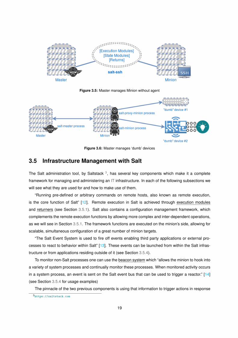
Figure 3.5: Master manages Minion without agent
Figure 3.6: Master manages ‘dumb’ devices
3.5 Infrastructure Management with Salt
The Salt administration tool, by Saltstack 3, has several key components which make it a complete
framework for managing and administering an IT infrastructure. In each of the following subsections we
will see what they are used for and how to make use of them.
“Running pre-defined or arbitrary commands on remote hosts, also known as remote execution,
is the core function of Salt” [12]. Remote execution in Salt is achieved through execution modules
and returners (see Section 3.5.1). Salt also contains a configuration management framework, which
complements the remote execution functions by allowing more complex and inter-dependent operations,
as we will see in Section 3.5.1. The framework functions are executed on the minion’s side, allowing for
scalable, simultaneous configuration of a great number of minion targets.
“The Salt Event System is used to fire off events enabling third party applications or external pro-
cesses to react to behavior within Salt” [13]. These events can be launched from within the Salt infras-
tructure or from applications residing outside of it (see Section 3.5.4).
To monitor non-Salt processes one can use the beacon system which “allows the minion to hook into
a variety of system processes and continually monitor these processes. When monitored activity occurs
in a system process, an event is sent on the Salt event bus that can be used to trigger a reactor.” [14]
(see Section 3.5.4 for usage examples)
The pinnacle of the two previous components is using that information to trigger actions in response3https://saltstack.com
19

to those kinds of events. In Salt we have the reactor system “a simple interface to watching Salt’s event
bus for event tags that match a given pattern and then running one or more commands in response.” [15]
(also in Section 3.5.4)
Most of the information may be static, but it can belong to each individual minion. This information
can be either gathered from the minion itself or attributed to it by the Salt system. The first “is called the
grains interface, because it presents salt with grains of information. Grains are collected for the operating
system, domain name, IP address, kernel, OS type, memory, and many other system properties.” [16].
The latter is called the pillar, which “is an interface for Salt designed to offer global values that can be
distributed to minions“ [17], in a private way relative to every other minion if need be. Examples of how
this information is gathered/attributed can be seen in Section 3.5.3.
3.5.1 Remote Execution
The underlying system that takes care of Remote Execution is composed of modules called “Execution
Modules” [12]. These are used to perform a wide variety of tasks, such as installing a system package,
starting/stopping services, executing shell commands and transferring files.
3.5.1.A Minion Targeting
The target component in the salt command allows one to filter in which minions the desired function
should run. The filter can be based of the minion’s system information (se expression 3.1), a regular
expression (see expression 3.2), a list of minion identifiers (see expression 3.3) or a combination of
different explicitly declared filters (see expression 3.4).
salt -G ’os:Debian’ test.ping (3.1)
salt -E ’web[0-9]’ test.ping (3.2)
salt -L web1,web2,web3 test.ping (3.3)
salt -C ’G@os:Debian and web* or E@db.*’ test.ping (3.4)
3.5.1.B Function
A function is part of an execution module, in the previous examples (expressions 3.1 to 3.4) the function
used is ping, from the execution module test, which returns a True value from the minion to the master.
Salt comes with a large collection of available functions from different execution modules. One can see
all available functions on the infrastructures’ minions by running the expression in 3.5, here we can also
see one of salt’s idiosyncrasies where instead of using ´ (quote) or ¨ (double quote) to delimit a minion’s
20

name or circumvent some shells’ substitutions one can escape the * character with a \ so it is not
interpreted by the shell itself, but by the salt system.
salt \* sys.doc (3.5)
3.5.1.C Arguments
In the end of a salt command one can pass two types of extra arguments. Either space-delimited
arguments to the function being executed (see expression 3.6), or keyword arguments that may be
specific the function being executed (see expression 3.7)
salt \* cmd.exec code python ’import sys; print sys.version’ (3.6)
salt \* pkg.install apache2 timeout=5 upgrade=True (3.7)
3.5.2 Configuration Management
The Salt State system is used to configure and automate the deployment of systems. This is commonly
called configuration management. Salt uses the term ”state” and ”states” because the configuration
management system is broken down into atomic state components that are flexible and can be used in
many ways to achieve configuration management.
States are defined in SaLt State (SLS) files, while they can be rendered in a variety of different
formats the most commonly used is Yet Another Markup Language (YAML)4, the default. One can also
use different templating engines to help form YAML or other data structure, the default is Jinja5 [18].
“YAML is a serialization format that, in Python, represents a data structure in a dictionary format” [18].
So, being a set of key/value pairs, each item has a unique key, which maps to a value. This value can,
in turn, contain a single item, a list of items or a set of key/value pairs. The key for a block in an SLS file
is called an Identifier (ID), if no name key is explicitly declared inside a block, the ID value will be copied
to the name6.
Both the State and the Pillar (see Section 3.5.3) systems use a file called top.sls (see Listing A.1)
to gather SLS files together and make them available to specific Minions, on specific environments. In
4http://yaml.org/5http://jinja.pocoo.org/6To note that all IDs must be unique, duplicates will make state compiling return an error.
21

Listing A.1 we can see that only one environment is declared, a minimal top file should at least have the
base environment, then we can see how different minions are being targeted, just like in Section 3.5.1.
However in a top file the default targeting type is of a regular expression for the Minion ID, in order to
use targeting by grains values one must explicitly declare the match type (i.e: - match: grain pcre)
3.5.2.A State Modules and Functions
By default, files within the /srv/salt/ directory define the Salt States. It is a format that ensures the State
a Minion will be in (see Listing 3.1).
Listing 3.1: SLS file syntax
1 <BLOCK ID>:
2 <STATE MODULE>.<FUNCTION>:
3 - name: <NAME TO BE PASSED TO FUNCTION>
4 - [KEY] : [VALUE]
In Listing 3.2 we can see three different State Modules being used: pkg, service and file. The pkg
State Module is tied to its Execution Module homonym, which takes care of whichever package manager
the underlying system possesses, In this example we are using the Function installed to ensure the
package defined by name is installed in the system. The service State Module will interact with a certain
service (start, stop, restart, reload, enable, disable, ...), specified by the name key, in this case we are
using the Function running, to ensure the service is started after the state executes.
Listing 3.2: Example SLS file
1 apache_webserver:
2 pkg.installed:
3 - name: apache2
4 service.running:
5 - name: apache2
6 file.managed:
7 - name: /etc/apache2/apache2.conf
8 - source: salt://env/apache2/conf/apache2.tmpl
9 - mode: 600
10 - user: root
11 - group: root
22

The file State Module interacts with files located on the Minion system, in this example we are using
the Function managed which produces a file on the Minion based on a template file, located on the
Master (hence the salt:// ), we can also specify the file ownership and permissions.
3.5.2.B Ordering State Execution
SLS files can be seen as both imperative, each state is evaluated in order of appearance within the state
file, and declarative, as states may include requisites which delay their execution [18, p. 42]. This is
achieved through the use of the certain keywords, such as:
require ⇒ the State in which it is declared in is not executed until every item in the list following the
argument has executed successfuly (Listing 3.3)
watch ⇒ depending on the State Module Function it is executing, it performs a specific action when
the State (or States) it is watching report changes upon its execution (Listing 3.4)
onchanges ⇒ similar to watch directive, but instead of requiring support from the executing State
Module (Listing 3.5)
onfail ⇒ allows for reactions to occur as a response to another state failing execution7 (Listing 3.6)
use ⇒ can be used for inheriting another state’s non-requirement values, in example when manag-
ing multiple files with the same user/group/mode values (Listing 3.7)
prereq ⇒ there may be some situations where a State is needed to run only if there are some
changes on another State, in example a Web application that makes use of Apache and when the
codebase on a production server changes the Apache service should be shutdown to avoid errors
with code still to be deployed (Listing 3.8)
Listing 3.3: require Example
1 apache_webserver:
2 pkg.installed:
3 - name: apache2
4 - require:
5 - file: apache_webserver
6 service.running:
7 - name: apache2
8 - require:
9 - pkg: apache_webserver
7Beginning in the 2016.11.0 release of Salt, onfail uses OR logic for multiple listed onfail requisites. Prior to the 2016.11.0release, onfail used AND logic. See Issue # 22370 for more information.
23

Listing 3.4: watch Example
1 apache_webserver:
2 pkg.installed:
3 - name: apache2
4 - require:
5 - file: apache_webserver
6 service.running:
7 - name: apache2
8 - require:
9 - pkg: apache_webserver
10 - watch:
11 - file: apache_webserver
12 file.managed:
13 - name: /etc/apache2/apache2.conf
14 - source: salt://env/apache2/conf/apache2.tmpl
15 - mode: 600
16 - user: root
17 - group: root
Listing 3.5: onchanges Example
1 apache_webserver:
2 pkg.installed:
3 - name: apache2
4 file.managed:
5 - name: /etc/apache2/apache2.conf
6 - source: salt://env/apache2/conf/apache2.tmpl
7 - mode: 600
8 cmd.run:
9 - name: /usr/libexec/apache2/post -changes -hook.sh
10 - onchanges:
11 - file: apache_webserver
24

Listing 3.6: onfail Example
1 primary_mount:
2 mount.mounted:
3 - name: /mnt/share
4 - device: 10.0.0.37:/share
5 - fstype: nfs
6
7 backup_mount:
8 mount.mounted:
9 - name: /mnt/share
10 - device: 192.168.13.37:/share
11 - fstype: nfs
12 - onfail:
13 - mount: primary_mount
Listing 3.7: use Example
1 apache2_conf:
2 file.managed:
3 - name: /etc/apache2/apache2.conf
4 - user: root
5 - group: root
6 - mode: 755
7 - watch_in:
8 - service: apache2
9 mysql_conf:
10 file.managed:
11 - name: /etc/mysql/my.cnf
12 - use:
13 - file: apache2_conf
14 - watch_in:
15 - service: mysql
25

Listing 3.8: prereq Example
1 {% set site_user = 'testuser ' %}
2 {% set site_name = 'test_site ' %}
3 {% set project_name = 'test_proj ' %}
4 {% set sites_dir = 'test_dir ' %}
5 apache2:
6 service.running:
7 - watch:
8 - file: codebase
9 codebase:
10 file.recurse:
11 - name: {{ sites_dir }}/{{ site_name }}/{{ project_name }}
12 - user: {{ site_user }}
13 - dir_mode: 2775
14 - file_mode: '0644'
15 - template: jinja
16 - source: salt:// project/templates_dir
17 - include_empty: True
18 shutdown_apache:
19 service.dead:
20 - name: apache2
21 - prereq:
22 - file: codebase
3.5.2.C The Top File
An infrastructure can be seen as being an applicational stack by itself, by having groups of different
machines set up in small clusters, each cluster performing a sequence of tasks. The Top file is were
the attribution of configuration role(s) and Minion(s) is made. This kind of file is used both for State (see
Section 3.5.2.E) and Pillar (see Section 3.5.3) systems.
Top files can be structurally seen has having three levels:
Environment (ε) A directory structure containing a set of SLS files, see Section 3.5.2.D
Target (Θ) A predicate used to target Minions Section 3.5.1.A
State files (Σ) A set of SLS files to apply to a target. Each file describes one or more states to be
executed on matched Minions
These three levels relate in such a way that Θ ∈ ε, and Σ ∈ Θ. Reordering these two relations:
26

• Environments contain targets
• Targets contain states
Putting these concepts together, we can describe a scenario in which the state defined in the SLS
file ‘env/apache.sls’ is enforced to all minions which names start with the word webserver (Listing A.1)
3.5.2.D Environments
When executing a state, the default state environment considered is base, we are able to define extra
environments and/or add directories to already existing environments. In Listing 3.9 we can see a key
definition in the Master config file, file roots, it defines the root location(s) to be used by the file server,
in this example we can see the base and dev environment root directories. In the dev environment the
file server aggregates SLS files from three different locations, in this case the states can not be matched
among the different directories as to ensure the reliability of delivering the correct state file.
Listing 3.9: Salt Master file server configuration
1 file_roots:
2 base:
3 - /var/lib/salt/states/base/
4 dev:
5 - /var/lib/salt/states/dev/
6 - /mnt/share/team1
7 - /mnt/share/team2
3.5.2.E Executing a State
The state namespace is defined regarding a specific directory structure and environment. A statesbase
name is determined by the directory the corresponding ‘init.sls’ SLS file is located. If, in example, we
have a SLS file located at ‘/mnt/share/team1/env/apache/init.sls’ we could execute it on every available
Minion with the command in Expression 3.8, using dev has the value for the keyword ‘env’. If we want to
see which changes would be made without really changing anything, an keyword ‘test’ could be passed
with the value ‘True’. If we wanted to execute, on all Minions, all states defined in the Top file (see
Listing A.1), we could use the command in expression 3.9 instead.
27

salt \* state.apply env.apache env=dev (3.8)
salt \* state.highstate (3.9)
3.5.3 Storing and Accessing Data
It is useful to use specific information across different minions. Its configuration is similar to the one used
by States, as we can see in Listing 3.10.
Listing 3.10: Salt Master pillar configuration
1 pillar_roots:
2 base:
3 - /var/lib/salt/pillar/base/
Listing 3.11: NTP SLS file
1 {% set ntp_conf = pillar['ntp']['ntp_conf '] %}
2 ntp:
3 pkg.installed
4 service.running:
5 - enable: True
6 - watch:
7 - file: {{ ntp_conf }}
8 {{ ntp_conf }}:
9 file.managed:
10 - template: jinja
11 - source: salt://env/ntp/etc/ntp.conf.tmpl
12 - mode: 644
13 - user: root
14 - require:
15 - pkg: ntp
16 ntp -shutdown:
17 service.dead:
18 - name: ntp
19 - onchanges:
20 - file: {{ ntp_conf }}
28

The way the information is defined and assigned is similar to states, but instead of defining State Module
executions we define information in the form of YAML, as show in A.2, where all minions are assigned
information regarding Network Time Protocol (NTP) server domain names and their NTP service con-
figuration file, this information can be used within states or even template files, using the ‘pillar’ keyword,
as exemplified in Listing 3.11.
3.5.4 Event System
In Chapter 2 we saw in Figure 2.2 a general view of the Salt System, which has a Reactor element, this
element is part of a more broad system, the Event System (represented in Figure 3.7) which is ‘used to
fire off events enabling third party applications or external processes to react to behavior within Salt’ [13].
The Event System has two main components:
Event Socket ⇒ from where events are published
Event Library ⇒ used for listening to events and forward them to the salt system
Figure 3.7: Saltstack Event System Flow Example
‘The event system is a local ZeroMQ PUB interface which fires salt events. This event bus is an open
system used for sending information notifying Salt and other systems about operations’ [15].
This associates SLS files to event tags on the master, which the SLS files in turn represent reactions.
This means that the reactor system has two steps to work properly. First, the reactor key needs to be
configured in the master configuration file, this associates event tags SLS reaction files. Second, these
reaction files use a YAML data structure similar to the state system to define which reactions are to be
executed.
29

Besides the tag, each Salt event has a data structure, a dictionary which can contain arbitrary infor-
mation about the event.
In Listing A.5 we can see an example of a Reactor State which is triggered by the Master on receiving
a salt/auth event tag (an automatic event sent from a Minion to the Master before being accepted by the
Master as its Minion), if the Minion trying to authenticate has in its Minion ID the domain .example.com
it is automatically accepted without human interaction.
Listing 3.12: Salt Master reactor configuration
1 reactor:
2 - 'salt/minion/<minion_id>/start ':
3 - /var/lib/salt/reactor/highstate.sls
4 - 'salt/auth':
5 - /var/lib/salt/reactor/auth -pending.sls
3.5.4.A Beacons
In Salt beacons allow a minion to hook into a several system processes and constantly monitor them,
so that when some activity occurs an event is sent to the Salt event bus and can be used to trigger a
reactor. These activities include: file system modifications, system load, service status, terminal activity,
disk usage and network usage.
Beacons are set up in the Minion configuration file with the beacons keyword, similar to the reactor
configuration. ‘The first beacon ever added was for the inotify system’ [18], it depends on the ‘python-
inotify’ (for Debian-based systems) package. If we wanted to monitor changes and/or deletion to, for
example a file named monitor within the /tmp/ directory we would add the block in Listing 3.13.
Listing 3.13: Salt Minion Beacon configuration
1 beacons:
2 inotify:
3 /tmp/monitor:
4 mask:
5 - modify
6 - delete_self
Assuming this is configured in Minion with ID ‘minion one’, when the file is modified/deleted an event
is launched with the tag salt/beacon/minion one/inotify//tmp/monitor. Within the event data structure,
30

information pertaining what activity actually occurred is returned, in Listing 3.14 we can see an example
of the event launched when the file is deleted.
Listing 3.14: Beacon event
1 Tag: salt/beacon/minion_one/inotify //tmp/monitor
2 Data: { '_stamp ': '2017 -10 -01 T06 :00:12.2557990 ',
3 'data': { 'change ': 'IN_DELETE_SELF ',
4 'id': 'minion_one ',
5 'path': '/tmp/monitor '},
6 'tag': 'salt/beacon/minion_one/inotify //tmp/monitor '}
Beacons can be used together with a Machine Learning (ML) agent (see Figure 3.8) in order to define
the configured values, adjusting them to what has happened in the past. This ML agent implementation
is not discussed in this work.
Figure 3.8: ML capabilities triggering a cleanup in a target file system
3.5.4.B Event Reactors
Similar to other components of Salt, Reactor state are interpreted in YAML by default, although they can
be written in other formats, we will keep using YAML for markup with Jinja templating when needed.
The structure for Reactor SLS files resembles State SLS files in that each block of data starts with
an unique ID, followed by a function and any arguments to be passed to that function.
A simpler reactor state than the one presented in Listing A.5 can be seen in Listing 3.15. This reactor
31

is used when the Master receives an event with the salt/minion/<minion id>/start tag (as defined in
Listing 3.12), and it executes the highstate function (referenced in Section 3.5.2.E).
Listing 3.15: highstate.sls Reactor State
1 highstate_run:
2 cmd.state.highstate:
3 - tgt: {{ data['id'] }}
32

4Development
Contents
4.1 Development Environment . . . . . . . . . . . . . . . . . . . . . . . . . . . . . . . . . . 35
4.2 Development Process . . . . . . . . . . . . . . . . . . . . . . . . . . . . . . . . . . . . . 38
4.3 Dashboards . . . . . . . . . . . . . . . . . . . . . . . . . . . . . . . . . . . . . . . . . . 38
33

34

In this chapter we will see how a full recipe can be written from scratch, what are the requirements to
achieve said recipe, and how one can see the status of a recipe on arbitrary minions. We will start with
the environment required for developing such recipes. Then we will go through the process of actually
writing a recipe, from modeling the solution to verifying it was executed as expected. Finally we will shed
some light on possible types of ‘Dashboards‘.
4.1 Development Environment
In Figure 4.1 we can see the different components that exist within the development environment.
Figure 4.1: Development Environment
The salt-cloud tool in the SysOp Workstation was used to launch the Master (bastion) within the
Openstack Cloud Provider. Before we can do this we need to specify which providers exists in our
environment, by setting up the file /etc/salt/cloud.providers.d/<provider>.conf, where ‘<provider>’ is
the provider name, in our case it will be ‘openstack-rnl’ (see Listing A.3). Then we must describe in
the /etc/salt/cloud.profiles.d/<profile>.conf file the machine types that can exist in our infrastructure,
as shown in Listing A.4. Finally, we define in a map file all the machines that are to be created when
invoking the command salt-cloud -m <infrastructure>.map
The salt-ssh tool was used to issue commands and apply Salt States to the infrastructure without
maintaining a permanent connection to either the bastion host or the rest of the infrastructure1. The
minimal configuration for salt-ssh to work is:
Saltfile ⇒ defines which configuration files and directories are to be used, extra option can be
passed to the salt-ssh tool.
1Public IPv4 addresses were limited to 1 (one)
35

roster ⇒ defines the minion infrastructure, as in this case the salt-ssh minion is unaware of its
“master”.
master ⇒ just like the master config file for salt-master, mainly used to define from where the SLS
files are read.
states ⇒ where the Top File ( see Section 3.5.2.C ) and the SLS files are located.
In Figure 4.2, we can see part of the directory structure which was used to work with the salt-ssh tool.
./
etc/
salt/
master ...see Listing A.8
roster ...see Listing A.7
pki/
master/
ssh/
salt-ssh.rsa ...contains SSH key used to connect to Openstack instances
salt-ssh.rsa.pub
srv
salt
top.sls
<SLS files >
pillar
top.sls
<SLS Pillar data >
Saltfile ...see Listing A.6
Figure 4.2: salt-ssh working directory structure
After having SSH access to the bastion, and running the ‘state.highstate’ (see Section 3.5.2.E) func-
tion, the bastion is now in the state defined in the Top File (see Listing A.9). We can now launch the
rest of the infrastructure with salt-cloud from within the bastion, as it ran the state ‘env.salt.cloud’ (see
Listing A.10), for this we can use the expression 4.1 from the salt-cloud base directory (see Listing A.10.
salt-cloud -P -m instances.map (4.1)
After salt-cloud finishes setting up the minions, we can manage the minions, from within the bastion,
with the salt command, just like demonstrated in Section 3.5.1.A.
36

4.1.1 Dependencies
As stated in its documentation “Salt should run on any Unix-like platform so long as the dependencies
are met” [19], and these dependencies are (as of Salt major version 2017):
• Python2 3.5.x
• msgpack-python3 - High-performance message interchange format
• YAML4 - Python YAML bindings
• Jinja25 - parsing Salt States (configurable in the master settings)
• MarkupSafe6 - Implements a XML/HTML/XHTML Markup safe string for Python
• apache-libcloud7 - Python lib for interacting with many of the popular cloud service providers using
a unified API
• Requests8 - HTTP library
• Tornado9 - Web framework and asynchronous networking library
There are also additional dependencies, according to the chosen Salt communication transport:
ZeroMQ:
• ZeroMQ10 >= 3.2.0
• pyzmq11 >= 2.2.0 - ZeroMQ Python bindings
• PyCrypto12 - The Python cryptography toolkit
RAET:
• libnacl13 - Python bindings to libsodium
• ioflo14 - The flo programming interface raet and salt-raet is built on
• RAET15 - UDP protocol2https://www.python.org/3https://pypi.python.org/pypi/msgpack-python4https://pyyaml.org/5http://jinja.pocoo.org/6http://www.pocoo.org/projects/markupsafe/7https://libcloud.apache.org/8http://docs.python-requests.org/en/master/9http://www.tornadoweb.org/en/stable/
10http://zeromq.org/11https://pyzmq.readthedocs.io12https://www.dlitz.net/software/pycrypto/13https://pypi.python.org/pypi/libnacl14http://ioflo.com/15https://github.com/RaetProtocol/raet
37

4.2 Development Process
After setting up the aforementioned Workstation (see Figure 4.1) we can start to write the manifests that
will be executed, also known as SLS files. We can define the development process as a step by step
process.
First we describe what actions we want to happen on a minion, let us take as an example the flow in
Listing 3.11 in a top-down approach:
Objective → to ensure a functional running NTP client
Requirements
• the NTP client software must be installed
• the NTP client configuration file must be in a predetermined state
• the NTP client service should be stopped when setting up the configuration file
• the NTP client service is to be running after the state completes
After defining these requirements we can start writing the SLS file by using the proper State Mod-
ules and state keywords for state ordering (as seen in Section 3.5.2.B). In this example we use the
pkg.installed state module function which maps to the system’s package manager, the service.running
for making sure that the service is left running (the watch keyword makes sure that the state in run only if
there were changes to the watched state). We then make use of the file.managed state module function
to generate the configuration file based on a template file. One thing to note is the service.dead that
uses the onchanges keyword, this makes sure it runs before the state it is “watching” is executed.
We can test the manifest with the command salt "*" state.apply ntp test=True and if every-
thing goes as expected apply it definitely without the test keyword, salt "*" state.apply ntp.
4.3 Dashboards
Although no Dashboards were implemented we present some information and performable actions that
could exist within one.
Implementing a dashboard would imply interacting with the underlying salt system (namely the salt-
master, salt-ssh or salt-cloud tools) from which one could interact with each managed device, there
should also exist a database of some kind in order to store information about the managed devices and
present that information in the dashboard.
The most simple screen could resemble a table with, at least, the following information:
minion id which represents the minion’s fully qualified domain name, within the salt infrastructure
last seen which shows when the minion last communicated with the master, in the form of a time
stamp
38

status one of online/offline, showing the running status of the minion agent or the connectivity status
of the underlying system (in the case of the minion not having a salt agent running)
last run which represents the last run execution module on the minion
Each of the rows should have the possibility of acting upon the corresponding minion, the following
are examples of what actions could be allowed:
shutdown/startup/restart → act upon the minion’s underlying system (i.e: Openstack) and perform
those actions to the minion’s OS.
execute → a textbox where one could enter valid shell commands to be executed on the minion, via
the cmd.run function.
highstate → execute the state.highstate function as described in expression 3.9.
states → where a list of available SLS are presented, to be executed via the state.apply function as
described in expression 3.9.
One could also gather other useful information, in example:
• CPU/RAM load
• Electric consumption
• Storage usage and variations through the day
In a big infrastructure that informations could be useful for reaching conclusions such as which type
of hardware consumes the most, or even the time periods at which the systems have most usage, either
for accounting or acquisition purposes.
39

40
5Evaluation
Contents
5.1 Environment . . . . . . . . . . . . . . . . . . . . . . . . . . . . . . . . . . . . . . . . . . 43
5.2 Testing . . . . . . . . . . . . . . . . . . . . . . . . . . . . . . . . . . . . . . . . . . . . . 46
5.3 Results . . . . . . . . . . . . . . . . . . . . . . . . . . . . . . . . . . . . . . . . . . . . . 47
41

42

Figure 5.1: Test Environment
5.1 Environment
In Figure 5.1 we can see the actual setup used in this thesis’ evaluation. The model used was the one
referred to in Figure 3.3(b). An OpenStack1 Cloud Controller was used to deploy the whole infrastructure
in to, in which the Operator is outside the Control layer network.
The following are the steps taken to get the whole infrastructure online, represented in Figure 5.2:
1. Using salt-cloud with the configuration files in Listing A.3, A.4, and the map file shown in Listing 5.2,
we launch the bastion instance (master1 in Figure 5.1 in the OpenStack provider. This also makes
sure the bastion is provisioned with salt-master with the ‘make master’ keyword.
2. At this time the master is online but has no SLS files, using salt-ssh we configure the SLS files in
the bastion, by applying the ‘bootstrap.states’ state (see Listing A.11).
3. After the previous state runs successfully, we can restart the salt-minion service on the bastion. As
soon as the salt-minion is launched and ready to receive commands from the master, it will send
a ‘minion start’ event, which will trigger the ‘highstate.sls’ reactor state (see Listing 3.15) and run
the states matching the minion id configured in the top file (see Listing A.9).
1https://www.openstack.org/
43

Workstation OpenStack Bastion munin1 web1 logger1 nfs1
launch()
init
ackprovision
return
return
strictstrict salt-cloud
bootstrap.states
return
strictstrict salt-ssh
event∗
reactor†
strictstrict bastion online
SSH session
launch()
init
ackprovision
return
return
parpar salt-cloud
event∗
reactor†
parpar instances online
SSH session
∗ The event considered is minion start† The corresponding reactor state should be highstate.sls (see Listing 3.15)
Figure 5.2: Process flow of the whole system initialization
44

4. Now that the bastion/salt-master is set up, we can start our infrastructure with using salt-cloud, with
the previous configuration files, but with the map file shown in Listing 5.3, from within a SSH ses-
sion or using the ‘cmd.run’ execution module function. The minion instances should be launched
and provisioned via the salt-cloud command.
5. Similar to step 3, the minions start up and and send a ‘minion start’ event, triggering the ‘high-
state.sls’ reactor state, leaving the minions in the state configured by the top file, the top file used
is the same as the one used for salt-ssh (see Listing A.9), and ready to be sent commands to via
the salt command (from within the bastion).
In addition to these steps, we can also use a configuration script made available by the cloud provider
(Listing A.18) and interact directly with our OpenStack framework through the openstack command
(Listing 5.1)
Listing 5.1: Interacting with the OpenStack framework
1 root@master1:~/salt-cloud# source agi-tenant01-openrc.sh
2 Please enter your OpenStack Password:
3 [0a7641]root@master1:~/salt-cloud# openstack
4 (openstack) usage show
5 Usage from 2017-09-18 to 2017-10-17 on project ...0a7641:
6 +---------------+-----------+
7 | Field | Value |
8 +---------------+-----------+
9 | CPU Hours | 1057.26 |
10 | Disk GB-Hours | 10570.15 |
11 | RAM MB-Hours | 380897.06 |
12 | Servers | 190 |
13 +---------------+-----------+
Listing 5.2: bastion map file
1 master_512:
2 - master1:
3 make_master: True
4 ssh_interface: public_ips
5 ssh_username: ubuntu
45

Listing 5.3: instances map file
1 minion_web_512:
2 - web1
3 minion_munin_512:
4 - munin1
5 minion_log_256:
6 - logger1
7 minion_256:
8 - nfs1
5.2 Testing
Three set of tests were designed in order to test different parts of this system.
The first relates to Virtual Machine (VM) creation within the cloud provider, it evaluates how long
it takes for the OpenStack framework to make sure a predetermined number of VMs, defined in map
files seen in Listing A.20, A.21, A.22 and A.23, do not exist and afterwards launching them again from
scratch, see Listing A.17.
The second set tests for execution times of Salt Execution Modules (see Section 3.5.1) and Salt
State Modules (see Section 3.5.2.A) since the command is issued on the master and until all targeted
minions return, which are:
• execution module test.ping, which makes the minion send a simple return ‘True’ to the master, see
Listing A.15
• SLS env.hosts, which configures the ‘/etc/hosts’ file, on all minions, see Listing A.13
• SLS env.salt.cloud on the bastion minion ‘master1’, see Listing A.24 and Listing A.25
• SLS env.salt.minion Listing A.26
• every SLS that each target minion has been mapped to in the top file, see Listing A.14
The third set tests the response time between the event being fired and the reactor state response
to reach the minion, for this we used auxiliary scripts to interact with the Salt API. One to listen to any
event arriving in the Master message bus, Listing A.16, and another to listen to a specific event in the
Master message bus, Listing A.19.
Besides the first set, which was run 10 (ten) times, every test was run 100 (one hundred) times,
and we present the average, median, minimum, maximum and standard deviation of Time To Complete
46

(TTC) for each in Table 5.1. The amount of iterations for each test were these due to system and time
constraints, the more tests we could have run the more data we would have to compare results.
(a) Benchmark: cloud (b) Benchmark: state test.ping
(c) Benchmark: state env.hosts (d) Benchmark: state env.salt.cloud
(e) Benchmark: state env.salt.minion (f) Benchmark: state highstate
Figure 5.3: Benchmark results
5.3 Results
The data files were read using an auxiliary Python script, Listing A.12, from which the aforementioned
statistical data was extracted.
In Figure 5.3 we can see that the results deviate a lot, which makes the results have less signifi-
cance, there are differences in tests which go to the order of 4000% (env.hosts). These were tests with
operations like simple file modifications, typically one line in a less than ten lines file, which do not justify
these time differences.
Equation (5.1) represents the standard deviation for the TTC values of each test:
σ Represents the standard deviation from the mean TTC.
N Is the total number of test runs.
47

xi is the actual TTC a run i took.
x is the mean TTC.
σ =
√∑Ni=1(xi − x)2
N − 1(5.1)
Table 5.1: Test Results
#Minions #RunsAverage
TTCMedian
TTCMinimum
TTCMaximum
TTCσ
TTCBenchmark: clouddestroy→create
seconds seconds seconds seconds seconds
T1 4 10 1394.559 1282.457 1233.402 2278.470 316.965T2 3 10 1270.986 1012.512 884.689 2695.600 638.226T3 2 10 984.4976 688.027 620.071 2884.033 687.806T4 1 10 510.621 471.646 347.945 764.963 152.451
#Minions #RunsAverage
TTCMedian
TTCMinimum
TTCMaximum
TTCσ
TTCBenchmark: statesstate @ minion
seconds seconds seconds seconds seconds
test.ping @ ”*” 5 100 1.007 0.932 0.867 2.270 0.234env.hosts @ ”*” 5 100 8.476 4.808 1.578 60.333 10.105
env.salt.cloud @ ”master1” 1 100 15.594 12.380 2.994 49.819 9.446env.salt.minion @ ”*” 5 100 44.319 39.731 27.892 111.373 16.638
highstate @ ”*” 5 100 108.018 101.119 44.602 200.184 34.326
#Minions #RunsAverage
TTCMedian
TTCMinimum
TTCMaximum
TTCσ
TTCBenchmark: reactorevent→state
seconds seconds seconds seconds seconds
minion start→ highstate 1 100 —- —- —- —- —-salt/auth→ auth pending 1 100 —- —- —- —- —-inotify→ env.salt.minion 1 100 —- —- —- —- —-
48

6Conclusion
Contents
6.1 Conclusions . . . . . . . . . . . . . . . . . . . . . . . . . . . . . . . . . . . . . . . . . . 51
6.2 Limitations and Future Work . . . . . . . . . . . . . . . . . . . . . . . . . . . . . . . . . 52
49

50

6.1 Conclusions
Throughout this document we saw how to interact with different layers of an IT infrastructure, based on
the Openstack framework, using SaltStack’s tools. Be it for remote execution, configuration manage-
ment, system monitoring or reaction triggering.
Overall it was an enriching experience, as we got to delve deeper into salt and Openstack interac-
tions. Although there is more information and experiments not shown in this document, this study shows
a great deal of capabilities both tools’, from where one can start to create more complex SLSs, reaction
flows, or even add ML capabilities to the infrastructure.
We saw how we can launch several different machines at the same time, and how to get them
bootstrapped to our salt system.
We analyzed the different salt components, namely:
• Execution Modules
• State Modules
• SLS files
• Event System
• Pillar System
We saw how to use salt-cloud to create and destroy VM instances within the Openstack framework,
how to use salt-ssh to manage minions that do not have a salt agent running and a brief view on
how to manage devices which have close to none computational capabilities (‘dumb’ devices). Each
implemented SLS state was presented, as well as how to use it in different ways, be it by means of
a direct call (see Equation (3.8)), defining it in the Top File, see Expression 3.5.2.C, and running the
highstate function like shown in Expression 3.9, or by means of a trigger to an event (see Section 3.5.4).
The tests performed where related to time taken to execute an action or a set of actions, the time
taken for each test to execute was not satisfactory, as the results were sometimes far apart, as we can
see by the σ TTC values in Table 5.1, or by the graphics presented in Figure 5.3.
However, we can conclude that salt is adequate for managing programmatically any component of
an IT Infrastructure (networks, networked devices, compute systems, storage systems and networks),
monitor said components and also manage information and meta-data associated with these devices,
in a secure fashion, regardless of having the requirements to run a management agent. Moreover
the results regarding the reactor benchmark (Table 5.1) were fast enough for its execution times to be
discarded, showing added value of making use of reactor states besides executing states manually.
51

6.2 Limitations and Future Work
It is to note the discrepancy of values between runs Figure 5.3, which shows that the provided OpenStack
framework may have not been the most adequate for this system, taking into account the minimum
requirements referred to in Section 3.3, the VMs made available to deploy had at maximum 1 CPU
and 512MB of RAM. As a workaround for the ram requirements, a swap file within each of the VM’s
file system was created and mounted, using the SLS env.swap, see Listing A.27. No workaround was
possible regarding the CPU limitations. This limited the amount of machines that could be launched,
as well as the possibility of demonstrating more functionalities in a feasible schedule. Other VMs being
executed within the provided Openstack system could have also hindered the tests performance.
Although no dashboard was implemented, some light was shed on how one would be designed,
which functions could be performed on the managed devices and what implies implementing one.
In spite of trying to setup Logger and Monitor minions, none were implemented as the overall infras-
tructure performance would be severely impacted as we can see from the tests already performed, in
Figure 5.3, where no such minions exist and the system is already slow.
52

Bibliography
[1] T. Delaet, W. Joosen, and B. Vanbrabant, “A survey of system configuration tools,” International
Conference on Large Installation System Adminstration, pp. 1–8, 2010.
[2] J. O. Benson, J. J. Prevost, and P. Rad, “Survey of automated software deployment for computa-
tional and engineering research,” 10th Annual International Systems Conference, SysCon 2016 -
Proceedings, 2016.
[3] Y. Demchenko, S. Filiposka, M. d. Vos, and ..., “ZeroTouch Provisioning (ZTP) Model and Infras-
tructure Components for Multi-provider Cloud Services Provisioning,” 2016.
[4] N. K. Singh, S. Thakur, H. Chaurasiya, and H. Nagdev, “Automated provisioning of application
in IAAS cloud using Ansible configuration management,” Proceedings on 2015 1st International
Conference on Next Generation Computing Technologies, NGCT 2015, no. September, pp. 81–85,
2016.
[5] E. Imamagic and D. Dobrenic, “Grid Infrastructure Monitoring System based on Nagios,” Proceed-
ings of the 2007 Workshop on Grid Monitoring, pp. 23–28, 2007.
[6] L. Yao and U. Australia), “Context as a Service: Realizing Internet of Things-Aware Processes
for the Independent Living of the Elderly,” in Service-Oriented Computing, 2016, no. October, pp.
763–779.
[7] K. Agrawal and H. Makwana, “Data Analysis and Reporting using Different Log Management Tools,”
International Journal of Computer Science and Mobile Computing, vol. 47, no. 7, pp. 224–229,
2015.
[8] C. Ebert, G. Gallardo, J. Hernantes, and N. Serrano, “DevOps,” vol. 33, no. 3, pp. 94–100, 2016.
[9] J. Networks, “Network Automation and Orchestration (White Paper),” pp. 1–8. [Online]. Available:
https://www.juniper.net/assets/us/en/local/pdf/whitepapers/2000541-en.pdf
[10] Saltstack, “SaltStack Enterprise 5.0 (White Paper),” 2016. [Online]. Available: https:
//saltstack.com/saltstack-enterprise-white-paper/
53

[11] ——, “Proxy Minion - Saltstack Documentation - v2017.7.1,” 2017. [Online]. Available:
https://docs.saltstack.com/en/latest/topics/proxyminion/index.html
[12] ——, “Remote Execution - Saltstack Documentation - v2017.7.1,” 2017. [Online]. Available:
https://docs.saltstack.com/en/latest/topics/execution/index.html
[13] ——, “Event System - Saltstack Documentation - v2017.7.1,” 2017. [Online]. Available:
https://docs.saltstack.com/en/latest/topics/event/events.html
[14] ——, “Beacons - Saltstack Documentation - v2017.7.1,” 2017. [Online]. Available: https:
//docs.saltstack.com/en/latest/topics/beacons/index.html
[15] ——, “Reactor System - Saltstack Documentation - v2017.7.1,” 2017. [Online]. Available:
https://docs.saltstack.com/en/latest/topics/reactor/index.html
[16] ——, “Grains - Saltstack Documentation - v2017.7.1,” 2017. [Online]. Available: https:
//docs.saltstack.com/en/latest/topics/grains/index.html
[17] ——, “Pillar - Saltstack Documentation - v2017.7.1,” 2017. [Online]. Available: https:
//docs.saltstack.com/en/latest/topics/pillar/index.html
[18] J. Hall, Mastering SaltStack - Take charge of SaltStack to automate and configure enterprise-grade
environments. Packt Publishing, 2015.
[19] Saltstack, “Dependencies - Saltstack Documentation - v2017.7.1,” 2017. [Online]. Available:
https://docs.saltstack.com/en/latest/topics/installation/#dependencies
54

AProject Code
Listing A.1: Example State top.sls file
1 base:
2 '*':
3 - ntp
4 - salt -minion
5 'kernel: Linux ':
6 - match: grain_pcre
7 - hosts
8 - python
9 'webserver*':
10 - apache
55

Listing A.2: Example Pillar ntp init.sls file
1 ntp:
2 servers:
3 - ntp1.tecnico.ulisboa.pt
4 - ntp2.tecnico.ulisboa.pt
5 ntp_conf: /etc/ntp.conf
Listing A.3: Example salt-cloud provider configuration
1 openstack -rnl:
2 # Configure the OpenStack driver
3 identity_url: http://< Openstack Identity IP Address>:5000/ v2.0/ tokens
4 compute_name: nova
5 protocol: ipv4
6
7 compute_region: RegionOne
8
9 # Configure Openstack authentication credentials
10 user: "[REDACTED]"
11 password: "[REDACTED]"
12 tenant: "agi -tenant01"
13
14 driver: openstack
15
16 # skip SSL certificate validation (default false)
17 insecure: true
56

Listing A.4: Example salt-cloud profile configuration
1 ubnt_xenial_512:
2 provider: openstack -rnl
3 size: m1.tiny
4 image: "Ubuntu Xenial server (16.04)"
5 ssh_key_file: pki/tenant01.pem
6 ssh_key_name: tenant01
7 ssh_interface: private_ips
8
9 ubnt_xenial_256:
10 provider: openstack -rnl
11 size: m1.micro
12 image: "Ubuntu Xenial server (16.04)"
13 ssh_key_file: pki/tenant01.pem
14 ssh_key_name: tenant01
15 ssh_interface: private_ips
16
17 ubnt_xenial_128:
18 provider: openstack -rnl
19 size: m1.nano
20 image: "Ubuntu Xenial server (16.04)"
21 ssh_key_file: pki/tenant01.pem
22 ssh_key_name: tenant01
23 ssh_interface: private_ips
24
25 ubnt_xenial_64:
26 provider: openstack -rnl
27 size: m1.pico
28 image: "Ubuntu Xenial server (16.04)"
29 ssh_key_file: pki/tenant01.pem
30 ssh_key_name: tenant01
31 ssh_interface: private_ips
32
33 minion_web_256:
34 provider: openstack -rnl
35 size: m1.micro
36 image: "Ubuntu Xenial server (16.04)"
37 ssh_key_file: pki/tenant01.pem
57

38 ssh_username: ubuntu
39 ssh_key_name: tenant01
40 ssh_interface: private_ips
41 script: bootstrap -salt
42 security_groups: salt -minion
43 minion:
44 master: [REDACTED]
45 grains:
46 role: webserver
47
48 minion_munin_512:
49 provider: openstack -rnl
50 size: m1.tiny
51 image: "Ubuntu Xenial server (16.04)"
52 ssh_key_file: pki/tenant01.pem
53 ssh_username: ubuntu
54 ssh_key_name: tenant01
55 ssh_interface: private_ips
56 script: bootstrap -salt
57 security_groups: salt -minion
58 minion:
59 master: [REDACTED]
60 grains:
61 role: monitor
62
63 minion_log_512:
64 provider: openstack -rnl
65 size: m1.tiny
66 image: "Ubuntu Xenial server (16.04)"
67 ssh_key_file: pki/tenant01.pem
68 ssh_username: ubuntu
69 ssh_key_name: tenant01
70 ssh_interface: private_ips
71 script: bootstrap -salt
72 security_groups: salt -minion
73 minion:
74 master: [REDACTED]
75 grains:
58

76 role: logger
77
78 master_512:
79 provider: openstack -rnl
80 size: m1.tiny
81 swap: 6GB
82 image: "Ubuntu Xenial server (16.04)"
83 ssh_key_file: pki/tenant01.pem
84 ssh_username: ubuntu
85 ssh_key_name: tenant01
86 ssh_interface: private_ips
87 script: bootstrap -salt
88 security_groups: salt -master
89 minion:
90 master: [REDACTED]
91 grains:
92 role: base
93
94 minion_256:
95 provider: openstack -rnl
96 size: m1.micro
97 image: "Ubuntu Xenial server (16.04)"
98 ssh_key_file: pki/tenant01.pem
99 ssh_username: ubuntu
100 ssh_key_name: tenant01
101 ssh_interface: private_ips
102 script: bootstrap -salt
103 security_groups: salt -minion
104 minion:
105 master: [REDACTED]
106 grains:
107 role: base
59

Listing A.5: Example Salt reactor state, auth pending.sls
1 {% if not data['result '] and data['id']. endswith('example.com') %}
2 minion_remove:
3 wheel.key.delete:
4 - match: {{ data['id'] }}
5
6 minion_rejoin:
7 cmd.cmd.run:
8 - tgt: master.example.com
9 - arg:
10 - ssh -o UserKnownHostsFile =/dev/null -o StrictHostKeyChecking=no "{{
↪→ data['id '] }}" 'sleep 10 && /etc/init.d/salt -minion restart '
11 {% endif %}
12
13 {# machine is sending new key -- accept this key #}
14 {% if 'act' in data and data['act'] == 'pend' and data['id']. endswith('
↪→ example.com') %}
15 minion_add:
16 wheel.key.accept:
17 - match: {{ data['id'] }}
18 {% endif %}
Listing A.6: Example Saltfile config used with salt-ssh
1 salt -ssh:
2 config_dir: etc/salt
3 max_procs: 30
4 wipe_ssh: False
Listing A.7: Example Saltfile config used with salt-ssh
1 master1: # the minion id
2 host: [REDACTED] # IP address or hostname of the minion
3 port: 22 # network port to connect via ssh
4 user: [REDACTED] # the user to authenticate as
5 sudo: True # whether or not to sudo to root , not enabled by
↪→ default
60

Listing A.8: Example Saltfile config used with salt-ssh
1 root_dir: .
2
3 file_roots:
4 base:
5 - srv/salt
6
7 pillar_roots:
8 base:
9 - srv/pillar
Listing A.9: Example top.sls with salt-ssh
1 base:
2 '*':
3 - software.salt.minion
4 - env.salt.minion
5 - env.hosts
6 'master1 ':
7 - software.salt.cloud
8 - env.salt.cloud
9 'web*':
10 - software.apache
11 - env.apache
12 - software.pgsql
13 'logger*':
14 - software.sentry
15 - env.sentry
16 'munin*':
17 - software.munin
18 - env.munin
61

Listing A.10: env.salt.cloud SLS
1 {% set root_dir = "/root/salt -cloud" %}
2
3 include:
4 - env.salt.master
5
6 deploy environment:
7 file.recurse:
8 - name: {{ root_dir }}
9 - source: salt://code/cloud
10 - user: root
11 - group: root
12 - file_mode: '0600'
13 - dir_mode: '0700'
14
15 /etc/salt/cloud.providers.d/openstack.conf:
16 file.symlink:
17 - target: {{ root_dir }}/openstack.conf
18
19 /etc/salt/cloud.profiles.d/openstack -rnl.conf:
20 file.symlink:
21 - target: {{ root_dir }}/cloud.profiles
Listing A.11: bootstrap.states SLS file
1 {% for state in ["env", "software"] %}
2 /var/lib/salt/states/{{ state }}:
3 file.recurse:
4 - source: salt://{{ state }}
5 - user: root
6 - group: root
7 - file_mode: '0600'
8 - dir_mode: '0700'
9 - makedirs: True
10 {% endfor %}
11
12 /var/lib/salt/states/top.sls:
62

13 file.managed:
14 - source: salt://top.sls
15 - template: jinja
16 - user: root
17 - group: root
18 - mode: '0600'[master*]
Listing A.12: parse tests.py
1 #!/usr/bin/env python
2 from dateutil.parser import parse
3 from numpy import median , average
4 import sys
5
6 if len(sys.argv) != 2:
7 print("usage:\n\tpython {} <map file >".format(sys.argv[0]))
8 exit(1)
9 file = open(sys.argv[1], 'r')
10 times = list()
11 for line in file:
12 d = parse(line)
13 times.append( (d.minute*60.000)+d.second +(d.microsecond/1000000.000000) )
14
15 mean_ = mean(times)
16 std_dev = sqrt(sum(map(lambda(x): (x - mean_)**2, times))/(len(times)-1))
17
18 print("Average: {}".format(average(times)))
19 print("Median: {}".format(median(times)))
20 print("Minimum: {}".format(min(times)))
21 print("Maximum: {}".format(max(times)))
22 print("Std dev: {}".format(std_dev))
63

Listing A.13: env hosts.sh
1 #!/usr/bin/env bash
2 for i in `seq 1 100`; do
3 { time salt \* state.apply env.hosts; } 2>&1 | \
4 grep -i real | \
5 awk '{print $2}' >> test times/state env hosts.times
6 done
Listing A.14: env highstate.sh
1 #!/usr/bin/env bash
2 for i in `seq 1 10`; do
3 { time salt \* state.highstate; } 2>&1 | \
4 grep -i real | \
5 awk '{print $2}' >> test times/state highstate.times
6 done
Listing A.15: test ping.sh
1 #!/usr/bin/env bash
2 for i in `seq 1 100`; do
3 { time salt \* test.ping; } 2>&1 | \
4 grep -i real | \
5 awk '{print $2}' >> test times/test ping.times
6 done
Listing A.16: event listen.sh
1 #!/usr/bin/env bash
2 salt-run state.event | while read -r tag data; do
3 echo $tag;
4 echo $data | jq --color-output .;
5 done
64

Listing A.17: cloud-init.sh
1 #!/usr/bin/env bash
2 map file="instances infrastructure.map"
3 if [ $# -eq 1 ]; then
4 map file=$1;
5 fi
6 # destroy vms
7 { time salt-cloud -dy -m $map file; } 2>&1 | \
8 grep real | \
9 awk '{print $2}' >> ${map file:-3}.destroy times
10 # give a few seconds for vm elimination
11 sleep 3
12 # create vms
13 { time salt-cloud -Py -m $map file; } 2>&1 | \
14 grep real | \
15 awk '{print $2}' >> ${map file:-3}.launch times
Listing A.18: agi-tenant01-openrc.sh
1 #!/usr/bin/env bash
2 export OS AUTH URL=http://[REDACTED]:5000/v3
3 export OS PROJECT ID=[REDACTED]
4 export OS PROJECT NAME="agi-tenant01"
5 export OS USER DOMAIN NAME="Default"
6 if [ -z "$OS USER DOMAIN NAME" ]; then
7 unset OS USER DOMAIN NAME;
8 fi
9 # unset v2.0 items in case set
10 unset OS TENANT ID
11 unset OS TENANT NAME
12 # In addition to the owning entity (tenant), OpenStack stores the entity
13 # performing the action as the **user**.
14 export OS USERNAME="[REDACTED]"
15 # With Keystone you pass the keystone password.
16 echo "Please enter your OpenStack Password: "
17 read -sr OS PASSWORD INPUT
18 export OS PASSWORD=$OS PASSWORD INPUT
65

19 export OS REGION NAME="RegionOne"
20 # Don't leave a blank variable, unset it if it was empty
21 if [ -z "$OS REGION NAME" ]; then
22 unset OS REGION NAME;
23 fi
Listing A.19: check events.py
1 #!/usr/bin/env python
2 import sys
3 import signal
4 import salt.utils.event as E
5 def signal_handler(signal , frame):
6 print 'Caught ^C, exiting!'
7 sys.exit(0)
8 def usage(progname):
9 print "usage: \n\t" + progname + " <tag to filter >\n"
10 signal.signal(signal.SIGINT , signal_handler)
11 event = E.MasterEvent('/var/run/salt/master ')
12 for data in event.iter_events ():
13 print data
Listing A.20: T1.map
1 minion_web_256:
2 - web1
3 minion_munin_512:
4 - munin1
5 minion_log_512:
6 - logger1
7 minion_256:
8 - nfs1
66
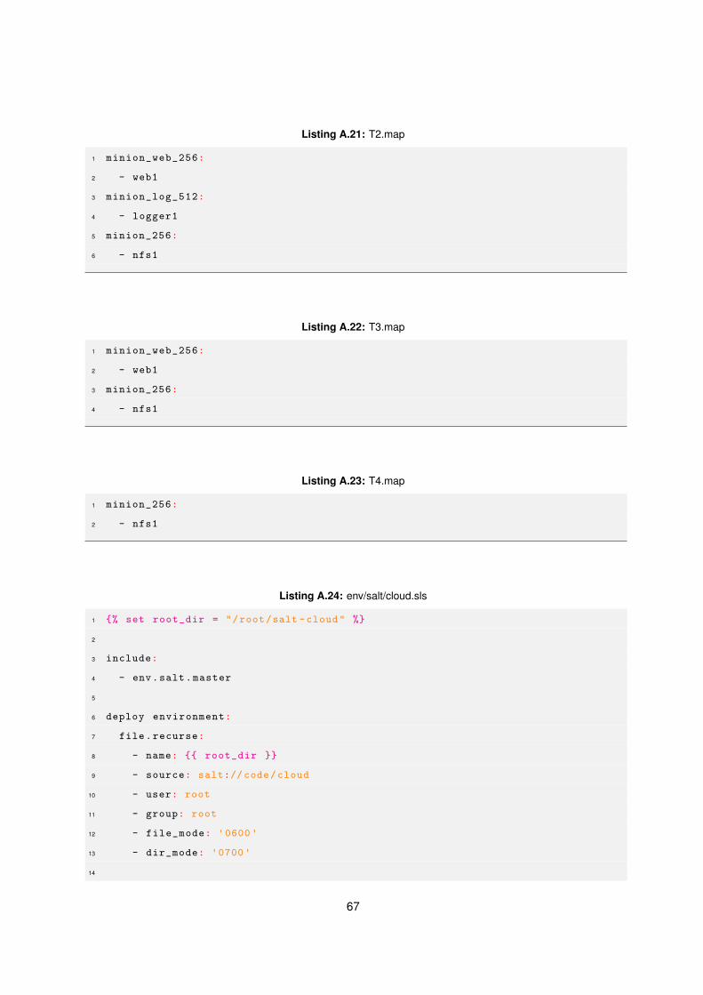
Listing A.21: T2.map
1 minion_web_256:
2 - web1
3 minion_log_512:
4 - logger1
5 minion_256:
6 - nfs1
Listing A.22: T3.map
1 minion_web_256:
2 - web1
3 minion_256:
4 - nfs1
Listing A.23: T4.map
1 minion_256:
2 - nfs1
Listing A.24: env/salt/cloud.sls
1 {% set root_dir = "/root/salt -cloud" %}
2
3 include:
4 - env.salt.master
5
6 deploy environment:
7 file.recurse:
8 - name: {{ root_dir }}
9 - source: salt://code/cloud
10 - user: root
11 - group: root
12 - file_mode: '0600'
13 - dir_mode: '0700'
14
67

15 /etc/salt/cloud.providers.d/openstack.conf:
16 file.symlink:
17 - target: {{ root_dir }}/openstack.conf
18
19 /etc/salt/cloud.profiles.d/openstack -rnl.conf:
20 file.symlink:
21 - target: {{ root_dir }}/cloud.profiles
Listing A.25: env/salt/master.sls
1 /etc/salt/master:
2 file.managed:
3 - source: salt://env/salt/etc/salt/master
4 - template: jinja
5 - user: root
6 - group: root
7 - mode: 770
8 service.running:
9 - name: salt -master
10 - reload: True
11
12 {% for dirname in ["states","reactor","pillar"] %}
13 /var/lib/salt/{{ dirname }}:
14 file.directory:
15 - makedirs: True
16 - mode: '0600'
17 - group: root
18 - user: root
19 - prereq:
20 - file: /etc/salt/master
21 {% endfor %}
22
23 deploy reactors:
24 file.recurse:
25 - name: /var/lib/salt/reactor
26 - source: salt://code/reactor
27 - user: root
28 - group: root
68

29 - file_mode: '0600'
30 - dir_mode: '0600'
31 - makedirs: True
32 - require:
33 - file: /var/lib/salt/reactor
Listing A.26: env/salt/minion.sls
1 /etc/salt/minion:
2 file.managed:
3 - source: salt://env/salt/etc/salt/minion
4 - template: jinja
5 - user: root
6 - group: root
7 - mode: 770
8 service.running:
9 - name: salt -minion
10 - reload: True
Listing A.27: env/swap/init.sls
1 {% set swapfile = "/root/extra.swap" %}
2 create swap file:
3 cmd.run:
4 - name: dd if=/dev/zero of={{ swapfile }} bs=10M count =300
5 - creates: {{ swapfile }}
6 make swap:
7 cmd.run:
8 - name: mkswap {{ swapfile }}
9 - onchanges:
10 - cmd: create swap file
11 {{ swapfile }}:
12 mount.swap:
13 - require:
14 - cmd: create swap file
69

70