Embed Size (px)
Citation preview

Schulich School of Engineering
Department of Mechanical and Manufacturing Engineering
Adaptive Control of Variable-Speed Variable-Pitch Wind Turbines Using RBF Neural Network
By: Hamidreza Jafarnejadsani,
Dr. Jeff Pieper , and Julian Ehlers
October 2012, London, ON
EPEC 2012

OVERVIEW
1• Introduction to Wind Turbine Control System
2• Wind Turbine Modeling
3• Torque Control Using RBF Neural Network
4• Pitch Control Using RBF Neural Network
5• Results of Simulations Using FAST Software
6• Future Work: L1-Optimal Control of Wind Turbines
2EPEC 2012

Wind Turbine Control System
Outer Loop (slow time response)
Aerodynamics
Mechanical Subsystems (Drive Train and Structure)
Inner Loop (fast time response)
Power Generator Unit
Pitch Servo
[Ref:Boukhezzar, B., H. Siguerdidjane, “Nonlinear Control with Wind Estimation of a DFIG Variable Speed Wind Turbine for Power Capture Optimization] 3
EPEC 2012

Control Strategy and Objectives
Variable-Speed, Variable-Pitch Control
Ideal power curve [Ref: Wind Turbine Control Systems, Page 51]
Control Objectives:
1) Energy Capture
2) Power Quality
3) Mechanical Loads
4EPEC 2012

Non-linear Equations of Wind Turbine
Drive-train shaft dynamics:
Elastic tower fore-aft motion:
Where:
• Ω: Rotor Speed
• d: Tower top Displacement
• λ: Tip-Speed Ratio
• Cp: Power Coefficient
• Vw: Wind Speed
• Ta: Aerodynamic Torque:
• Tel: Generator Torque
• Fa: Thrust Force
• M t, Ct, Kt: Equivalent Mass, Damping
Ratio, and Stiffness of Tower 5EPEC 2012

Non-linear Equations of Wind Turbine
• λ: Tip-Speed Ratio
• Ta: Aerodynamic Torque
• Fa: Thrust Force
• Cp: Power Coefficient
• Control Inputs: Generator Torque (Tel) & Pitch Angle (βe) 6
EPEC 2012

FAST Wind Turbine Simulation Software
FAST: (Fatigue, Aerodynamics, Structures and Turbulence) is an Aero-
elastic Simulator.
Developed by NREL(National Renewable Energy Laboratory), Golden, CO
A Variable-Speed Variable-Pitch Wind Turbine:
NREL-Offshore-Baseline-5MW (Parameters developed by NREL)
Rating 5 MW
Rotor Orientation, Configuration Upwind, 3 Blades
Control Variable Speed, Variable
Pitch
Rotor, Hub Diameter 126 m, 3 m
Hub Height 90 m
Cut-In, Rated, Cut-Out Wind
Speed
3 m/s, 11m/s, 25 m/s
Cut-In, Rated Rotor Speed 6.9 rpm, 12.1 rpm
Rotor Mass 110,000 kg
Optimal Tip-Speed-Ratio 7.55
Rated Generator Torque 43,100 Nm
Maximum Generator Torque 47,400 Nm
Rated Generator Speed 1174 RPM
7EPEC 2012

Radial-Basis Function (RBF) Neural Networks
A two-point radial-basis function [Ref: Stanislaw H Zak, Systems and Control, pg 495]
8EPEC 2012
RBF Neural Networks Approximate the Nonlinear Dynamics of
Control System
Robust to Uncertainties and Disturbances in the System
Fast Time Response

Torque Control
At wind speeds lower than rated wind speed
Maximum power capture
Constant Pitch Angle
Equation is in the affine form
RBF NN Approximator
9EPEC 2012

Control Design and Updating Rule Using Lyapunov Theory
Tracking error:
Controller:
Lyapunov function:
Robust weight update using e-modification method:
10EPEC 2012

Pitch Control
At wind speeds Higher than rated wind speed
Limiting the power capture at nominal capacity of wind turbine
Constant generator torque
Equation is in the non-affine form
11EPEC 2012

Control Design and Updating Rule Using Lyapunov Theory
Transformation (Inverse Dynamics Method)
Approximating ideal controller using NN:
Mean value thorium:
Lyapunov function:
Robust weight updating rule :
12EPEC 2012
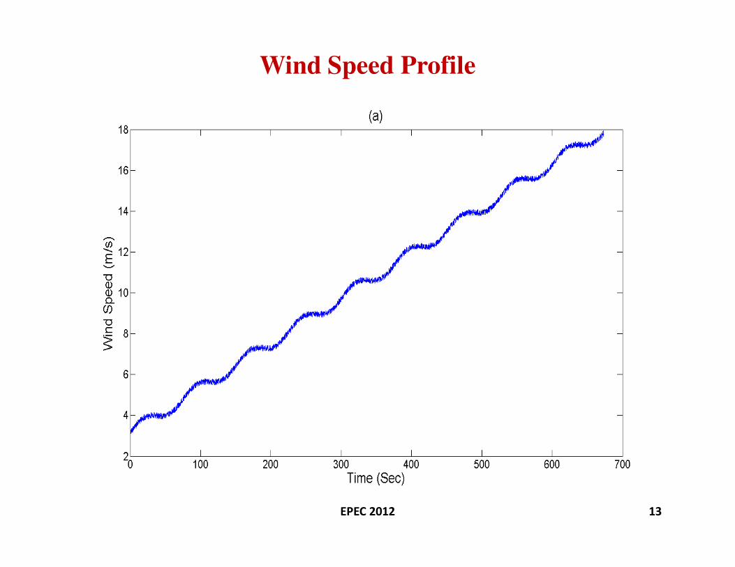
Wind Speed Profile
13EPEC 2012

Results (Electrical Output Power)
14EPEC 2012
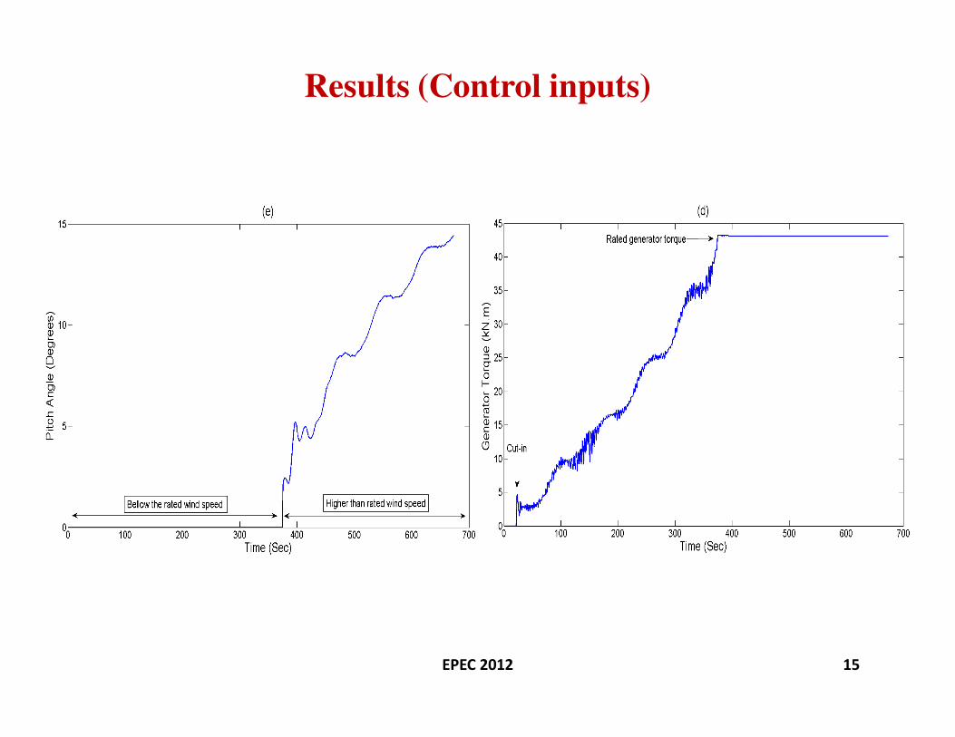
Results (Control inputs)
15EPEC 2012

Results of Simulation Using FAST Software for
Region I (Maximum Power area)
• Wind Inputs: TurbSim-generated 24 x 24 grids of IEC Class A
Kaimal-spectrum turbulence
• Six turbulence realizations per mean wind speed are simulated.
EPEC 2012 16
0
500
1000
1500
2000
2500
3000
3500
0 2 4 6 8 10 12
Po
we
r (k
W)
Average Wind Speed
Electrical Power Output
Neural Network Controller
PI Controller

Results of Simulation Using FAST Software for
Region III (Rated Power Area):
Comparing The Performance of Controllers:
1) Gain-Scheduled PI-Control ( Developed by NREL)
2) Proposed Adaptive Neural Network Control
EPEC 2012 17

Results (Electrical Output Power)
EPEC 2012 18

Results (Control input1: Generator Torque)
EPEC 2012 19

Results (Control input2: Pitch Actuation)
EPEC 2012 20

Introduction to L1-Optimal Control
The final purpose of L1-optimal control is to find a controller (K) to stabilize the closed-loop system and minimize the L∞-norm between disturbance input(w) and performance output (z).
Why L1-Optimal Control?
1) Persistent exogenous disturbances and noises. These inputs obviously have infinite energy(L2-norm). However, they have bounded magnitudes(L
∞-norm).
• EX: varying wind conditions that face the wind turbine.
2) Direct time-domain performance specifications
• EX: overshoot, bounded magnitude, bounded slope, or actuator saturation
LMI (Linear Matrix Inequality) Approach to L1-Optimal Control
LMI method results in a convex minimization problem subject to LMI constraints21EPEC 2012

Thank You For Your
Attention
??
22EPEC 2012