Embed Size (px)
Citation preview

^avi}, M. V., et al.: Adaptive Continuously Variable Transmission ... THERMAL SCIENCE: Year 2016, Vol. 20, Suppl. 2, pp. S525-S536 S525
ADAPTIVE CONTINUOUSLY VARIABLE TRANSMISSION USED FOR
MAINTAINING STATIONARY REGIME OF DRIVING MACHINE
by
Maja V. ^AVI]*
, Marko M. PEN^I], and Miodrag @. ZLOKOLICA
Faculty of Technical Sciences, University of Novi Sad, Novi Sad, Serbia
Original scientific paper DOI:10.2298/TSCI151004035C
Continuously variable transmissions (CVT) contained in many complex systems of modern techniques can be designed as purely mechanical systems that due to their structure make self adjustments, meaning they can change their own char-acteristics in order to adapt to external parameters variations. In this way adap-tive CVT can be used for automatic regulation of a system. A general approach to dynamical description of adaptive CVT behaviour as a non-holonomic, com-pletely mechanical system has been developed. For dynamic description of me-chanical non-holonomic system, Appell`s differential equations are used. By nu-merically solving differential equations of motion, answers about the working stability as well as dynamic and kinematic behaviour of the observed CVT system are obtained thus proving CVT functional applicability as a regulator for a changeable working regime. Presented approach can be used in choosing opti-mal parameters for the synthesis of this type of transmissions.
Key words: continuously variable transmissions, non-holonomic mechanical system, adaptive mechanical system
Introduction
The general trend in modern mechanical design is aimed at creating automatic ma-
chines which function with as little involvement from human operators as possible. Due to
their adaptability the parts of the machine that automatically control/regulate the process can
provide optimal kinematic and dynamical working regime under any exploitation parameters
to the working elements, and even more importantly from an energy efficiency stand point, to
the motor as well. Thus, they become a very important part of machine, since they not only
make sure that the given task is executed but can also improve the machines work characteris-
tics. The working components in systems for automatic control/regulation are usually hydrau-
lic or pneumatic in nature, while the sensors and control structures are electronic. The pres-
ence of a system with different medium (hydraulics/pneumatics) significantly complicates the
structure and functioning of the machine while the use of electronics can be problematic be-
cause of the need for specialized software. Its alternative is presented here as the use of com-
pletely mechanical, adaptive systems that due to their structure do self adjustments, meaning
they can change their own characteristics in accordance with external parameters. For exam-
_______________
* Corresponding author; e-mail: [email protected]

^avi} M. V., et al.: Adaptive Continuously Variable Transmission ... S526 THERMAL SCIENCE: Year 2016, Vol. 20, Suppl. 2, pp. S525-S536
ple, they can change their geometry, which changes their kinematic and dynamical behaviour,
and therefore the final performance of the machine.
Continuously variable transmissions
Continuously variable transmissions (CVT) are mechanical systems that can change
their transmission ratio according to either a given program or signals received from the ma-
chine during work, for example the speed or force. They can be sorted by structure [1]:
(1) CVT that transmit the load through friction
– frictional CVT (half toroidal, full toroidal, etc.),
– belt CVT (cone type, variable pulley type, etc.), and
(2) CVT that transmits the load through teeth:
– gear CVT,
– chain type CVT.
They are traditionally used in all transmissions with variable working regimes:
winding and unwinding machinery in the paper, textile, cable and metal industry, dozers,
loaders, machinery in the processing industry, machinery for centrifugal moulding, etc.
Lately their use has skyrocketed in the automobile industry because it has become
apparent that CVT systems not only greatly increase automobile performance and engine life
expectancy but also reduce greenhouse gas emissions [2, 3]. All types of CVT can be found in
contemporary automotive industry. Nearly all snowmobiles, utility vehicles, golf carts
and motor scooters use CVT, typically the rubber belt/variable pulley variety Torotrak Ltd.
implemented the first full toroidal friction system to be manufactured for outdoor power
equipment [4]. In 1987 the Ford Fiesta and Fiat Uno became the first European cars to be
equipped with steel-belted CVT [5]. Fiat in 2000 introduced a cone-type CVT as an option
on its models Punto and Lancia. After researching pulley type CVT for some time, Honda
also introduced their own version in the 1995 Honda Civic [6]. In the late 1990’s, Nissan was
the first car manufacturer to introduce a frictional CVT to the market in recent years. Their
toroidal CVT, named the Extroid [7], was available on the Japanese market Nissan Glo-
ria and Skyline. In 2006, Nissan announced that they will use CVT for all automatic versions
of their vehicles in North America, thus establishing CVT as a mainstream transmission sys-
tem. Audi has, since 2000, offered a chain type CVT (Multitronic) [8] as an option on A5 and
A6 models. Most of the mentioned CVT systems use electronics as control component, and
because of the magnitude of the forces involved, hydraulics for the working components [9,
10]. A large number of agricultural machines also have CVT [11] – the CVT allows forward
motion speed of the combine to be adjusted independently of the engine speed thus enabling
the operator to slow or accelerate as needed to accommodate variations in thickness of the
crop.
The CVT are also a very important component in power plants – especially in wind
generators [12]. A major problem regarding wind turbines is that wind intensity and force are
time variables. To obtain an efficient connection between the wind turbine and the distributive
network, variations in frequency and induced power must be within very narrow boundaries
which imply implementation of CVT in the wind generator system. From [13, 14], it is plain
to see that the use of CVT greatly increases the efficiency of wind turbines, but, still, auto-
matic control is done by electronics.

^avi}, M. V., et al.: Adaptive Continuously Variable Transmission ... THERMAL SCIENCE: Year 2016, Vol. 20, Suppl. 2, pp. S525-S536 S527
The adaptive CVT should have a more complex structure to be able to do the actual
self adjustments than typical basic CVT: there should be an additional mechanism with an
element that will perform an additional motion – the control motion which will change the
kinematic structure of the basic CVT as needed, and in addition, the main motion as well.
Obviously, this introduces another degree of freedom into the system. Also, the additional
mechanism has to have structural characteristics needed to appropriately and reliably correct
the main motion. Since both the basic CVT and additional mechanism are mechanical sys-
tems, the behaviour of the whole system can be described by the laws of mechanics. In [15,
16] the development of dynamic model and friction stability analysis of CVT system which
uses mechanical system to move the working components – screw pair, has been shown. An
electronic system was used for automatic control. The parameter required to maintain is the
prescribed value of the output angular velocity. The Rout-Hurwitz and Vyshnegradsky prob-
lem methods are used to determine the system parameters needed for the motion to be stable.
A geared CVT, shown in [17, 18], is designed as a planetary-differential transmission with
two degrees of freedom and one input, where the control degree of freedom (the motion) turns
on according to the variation of the outside load. The paper [19] shows a completely me-
chanical system that maintains the output angular velocity during load and work condition
variations, the additional mechanism being a lever mechanism with a Watt governor. During
external load variations, the system steadily and in proper time maintains the output angular
velocity.
A very significant type of regulation, especially in the fields like transportation and
energy production, is maintaining the stationary mode of a working machine (motor) during
load variation. That mode is most economic because the motor power is fully utilized. For this
case, a self-adjusting CVT will be considered. A solution for the adaptive CVT (basic CVT +
additional mechanism) similar to the one from [19] will be proposed; the model will be
formed, behaviour simulation executed and stability of the system examined.
Method for the dynamic analysis
of non-holonomic systems
According to [1], the basic CVT represents a non-holonomic mechanical system.
The transmission ratio of CVT, i.e. the equation connecting the input and output angular ve-
locity represents a non-holonomic connection. Due to the presence of non-holonomic con-
straints, it is impossible to use the second form of Lagrange's equation, so some other kinds of
approach from analytical mechanics have to be used, most notably the Lagrange multiplier
method and Appel's equations [20]. The equations of motion are also attainable through the
direct use of general dynamical equations, as well as through the application of kinetostatic
methods. The latter two methods call for decomposition of the system and the analysis of
every single element, as well as taking into consideration the internal reactions of the system,
making them less than ideal in this case. For complex systems, the Lagrange multiplier
method is computationally demanding, so the procedure used for formation of CVT model
will be using Appel's equations. The convenience of using Appel's equations is that already
existing typical equations for the acceleration of a moving body can be used.
A general dynamical system can be described with n generalized coordinates: q1, q2,
...,qn. Let there be k non-holonomic connections in the system:

^avi} M. V., et al.: Adaptive Continuously Variable Transmission ... S528 THERMAL SCIENCE: Year 2016, Vol. 20, Suppl. 2, pp. S525-S536
ρj j ρ1
0, 1,2,...,n
j
A q A k
(1)
Aj and A are coefficients in function of qi and t only.
Appell`s equations are given in the following form:
ν
ν
** 1,2,..., ,
SQ p p n k
q
(2)
Energy of acceleration of a system *S is sum of energies of accelerations of its
components*
iS .
For bodies performing planar motion, the energy of acceleration can be calculated:
2 2
i i Ci C i
* 1
2S m a J (3)
For bodies performing motion in space, the energy of acceleration can be calculated:
2 2 2 2
i i translation i rotration i Ci ξ ξ η η ς ζ
* * * 1 1
2 2
S S S m a J J J
η ξ ξ η ζ η ζ ξ ζ ξ ηJ J J J J J
(4)
Generalized forces Qv
* are determined using the principle of virtual work.
Dynamical behaviour of the adaptive CVT
The frictional adaptive CVT with half balls is shown in fig. 1. Power is transferred
from the driving machine in this case an electro motor (EM) to CVT input link 1, then,
through disc 3 to the output link 2 and, finally, to the working machine. Gearboxes GB1 and
GB2 with constant transmission ratios can be integrated into the whole transmission system if
needed. Variation of the output angular velocity happens due to a change in position of con-
tact points A and B of disk 3 and links 1 and 2, respectively. Disk 3 is mounted on link 4 in
such a way that it can rotate both around its axis and also (along with link 4) around the axis
through O4. Thus, the distance between the contact points on input and output links and their
respective axes of rotation have been changed giving the variable transmission ratio between
links 1 and 2.
Spring controlled centrifugal governor of Wilson-Hartnell type (fig. 2) – GOV is in-
tegrated into the transmission system in order to ensure closed automatic regulation. Balls 1
with mass mt are connected by two springs 2, with the spring constant c1, called the main
springs. Levers 3 have two arms – vertical, with length l1 and horizontal with, length l2. The
horizontal arms have rollers 4 at their end which are placed in a grove on slider 5, with mass
mk and a moment of inertia Jk. The adjustable auxiliary spring 6 with a spring constant c2 is
connected to the slider by lever 7. Governor elements rotate around the governor axis while
slider can perform an additional translational motion along the axis. Centrifugal force FC and
slider displacement x are defined:
2 2
2 4 2 4 1C0 C 1 2 0 1 22 2
1 1 23 3
4 4
F F t c c r r t c c x
(5)

^avi}, M. V., et al.: Adaptive Continuously Variable Transmission ... THERMAL SCIENCE: Year 2016, Vol. 20, Suppl. 2, pp. S525-S536 S529
Figure 1. Continuously variable transmission with a frictional adaptive CVT as a closed mechanical regulating system
For a stationary working regime 2 = const i. e. r(t) = const there is no change in
slider position (x = const, 0x ) so link 5 – the lathe and link 4 do not move. Rotation is
transferred from the output shaft to the governor shaft via gears 6 and 7. If 2 changes, r and x
will change as well, resulting, at the end, in the change of position of disc 3 and consequently
in the change of transmission ra-tio of the basic CVT. Dumper DAM with dumping coeffi-
cient b is connected to the slider in order to stabilize motion.
Dynamical analysis will be
done by using Appell’s equations
for non-holonomic systems.
Three generalized coordinates
which describe the system are:
rotation of the input shaft , rota-
tion of the output and displace-
ment of lathe x which indirectly
defines the position of element 3.
Rotation of output shaft 2 and
displacement x are adopted as
independent generalized accelera-
tions, so Appell’s equations for
this system are given:
φ22
**S
Q
,
x
**S
Qx
(6)
Figure 2. Spring controlled centrifugal governor

^avi} M. V., et al.: Adaptive Continuously Variable Transmission ... S530 THERMAL SCIENCE: Year 2016, Vol. 20, Suppl. 2, pp. S525-S536
The non-holonomic connection between generalized co-ordinates and is de-
fined by the following differential equation:
21 v 2 1 4 2
1
tan 0R
iR
(7)
The energy of acceleration for this system is:
2 2
1 EM GB1 1 2 GB2 WM 6 7 2k
* 1 1
2 2S J J J J J J J J J
2 2 2 2 2 2
3 2 3 4 3ξ 3 3ζ 4 4 4 k T
*1 1 1 12
2 2 2 2m R R J J J m x S
(8)
The connection between 1 and 2 is obtained by differentiating non-holonomic
connection (7).
The equation connecting the tangential velocities of elements 2 and 3 in point B is as
following:
2 43 3 2 2 3 2
3
siny
RR r
R
(9)
Angular acceleration 3 is obtained by differentiation of eq. (9).
To express through generalized co-ordinate x, the following geometric connection
is used:
4 40
4
x
R (10)
Angular velocity 4 and angular acceleration 4 are obtained by differentiation of
eq. (10).
Energy of acceleration ST of regulator balls is:
2
T T T
* 1 2
S a m
(11)
Acceleration of point T – the centre of governor ball is:
T pn pt rn rt k a a a a a a
(12)
Magnitudes of normal pn and tangential pt components of the transmission accel-
eration of point T are apn = (r0 – x) 22 and apt = (r0 – x) 2 , respectively. Magnitudes of the
normal rN and tangential rT components of relative acceleration of point T are ar n= 1 2 and
ar t= 1 , respectively. The magnitude of Coriollis acceleration k is ak = 2 1 2. Acceleration for point T is:
2 2 2
2
T pn rn rt pn pt Kcos sin a a a a a a a (13)
Angle can be expressed though generalized co-ordinate x:

^avi}, M. V., et al.: Adaptive Continuously Variable Transmission ... THERMAL SCIENCE: Year 2016, Vol. 20, Suppl. 2, pp. S525-S536 S531
0
1
cos
r d x
(14)
First and second derivate of eq. (14) are:
1/2
2211 0
sin
x x
r d x
(15)
2
0
1/2 3/22 22 2
1 0 1 0
x r d xx
r d x r d x
(16)
With eq. (11) through eq. (16) energy S*T is defined.
Generalized forces are defined using the principle of virtual work:
2 1 22 2 1 4 2 2 2
1
* * tan 2x
RA Q Q x M M x x b x x
R x x
(17)
The torque on shaft 1 depends on the torque of the driving machine and equals to:
1 GB1 EMM i M (18)
In the case of asynchronous motor, for nominal working regime, the torque on the
shaft and its angular velocity are connected via relationship MEM = A – BωEM.
Coefficients A and B depend on the power and type of motor.
The torque on the shaft of element 2 depends on the load on working machine and
equals:
2 GB2 WMM i M t (19)
The load is generally a variable and depends on the particular type of the working
machine. For example, the MWM of a fan is a constant, while in machines for winding and
unwinding, it equals MWM = C ± D t , etc.
The generalized force for 2 is:
φ2 GB1 EM GB2 WM
*Q i A B i M t (20)
The current deformation of spring 1 is L1 + 2ΔL 1 – 2x 1/ 2, so the potential energy
can be written in the following form:
2
11 1 1 1
2
12 2
2
c L L x (21)
The current deformation of spring 2 is L2 + 2ΔL 2 – x 3/ 4, so potential energy can
be written in the following form:
2
32 2 2 2
4
1
2
c L L x (22)

^avi} M. V., et al.: Adaptive Continuously Variable Transmission ... S532 THERMAL SCIENCE: Year 2016, Vol. 20, Suppl. 2, pp. S525-S536
The generalized force for coordinate x is:
31x 1 1 1 2 2 2
2 4
* 2 2 2Q c L L x c L L x bx
(23)
Finally, differential equations that describe the dynamical behaviour of the adaptive
CVT are:
222
1 EM GB1 40 0 2 GB2 WM 6 7 k1 4
2 tan 2 ( ) +T
R xJ J J m r x J J J J J J
R R
1
22 23ξ 40 2 1 EM GB1 40 40
3 4 1 4 4 4
sin 2 tan cosR Rx x x x
J J J JR R R R R R
1/22
0 2T 0 GB1 40 2
1 1 4
4 1 tanr d x R x
m r x x BiR R
2GB1 GB2 40
1 4
tan 0R x
Ai i C DtR R
(24)
and:
22
2 3 03 3ξ 4 K T2 2 2
14 4 4
1 12 1
R R r d xm J J m m x
R R R
12
20 0T
1 1 1
21
r d x r d xmx
2 31T 0 2 1 1 1 2 2 2
2 4
2 2 2 2 0m r x bx c L L x c L L x
(25)
Results
Using eqs. (24) and (25), behaviour simulation of adaptive CVT was ran in MAT-
LAB, for a number of different load variations. The results are shown in figs. 3 and 4 in the
form of time-histories of relevant variables: input and output angular velocities and control
motion (motion of lathe). For the system depicted on fig.1, the parameter values are:
J1 = 2.6 kgm2; JEM+ JGB1= 0.2 kgm
2; J2 = 0.5 kgm
2; J3 = 0.1 kgm
2; J3 = 0.05 kgm
2;
J4 = 0.65 kgm2; JGB2 = 0.1 kgm
2; JWM = 0.5 kgm
2; J6 = J7 = 0,04 kgm
2; Jk = 0.01 kgm
2;
R1 = 0.3 m; R2 = 0.15 m; R3 = 0.075 m; R4 = 0.225 m;
m3 = 2.8 kg; mT = 0.2 kg; mK = 0.2 kg; 1 = 2 = 3 = 4 = 0.15 m; L1 + 2ΔL1 = 0.205 m;
L2 + ΔL2 = 0.105 m; c1 = 681 Nm–1
; c2 = 1363 Nm–1
; iGB1 = 7; iGB2 = 1; b = 5000 [Nsm–1
];
MEM = A – BωEM; A = 1500 [Nm]; B = 188.5 [Nms–1
];
t0 = 0 s; 0 = 26.5o; 20 = 41.89 [s
–1]; xo = 0 m;
Case 1. MWM = C + D t , C = 175 Nm; D = 14.6 Nms-1
;

^avi}, M. V., et al.: Adaptive Continuously Variable Transmission ... THERMAL SCIENCE: Year 2016, Vol. 20, Suppl. 2, pp. S525-S536 S533
Case 2. WM
, 4s
4 / 4, 4s 8s
, 8s
C t
M C D t t
D t
, C = 175 Nm; D = 14.6 Nms-1
;
The diagrams show that the proposed adaptive mechanism system fulfils the re-
quested function – it maintains the output angular velocity of the driving machine. At the
beginning of motion, as the load changes so does 1. In case 1, since variation of M2 is con-
tinuous, the change in 1 is negligible, while in case 2, since M2 variation is uncontinuous, the
change in 1 is more significant, but after a period of 10 seconds, a stationary working regime
has been established.
Figure 3. Time histories of output moment M2, output angular velocity 2,
input angular velocity 1 and displacement of the lathe x, case 1
Figure 4. Time histories of output moment M2 and input angular velocity 1, case 2
^avi} M. V., et al.: Adaptive Continuously Variable Transmission ... S534 THERMAL SCIENCE: Year 2016, Vol. 20, Suppl. 2, pp. S525-S536
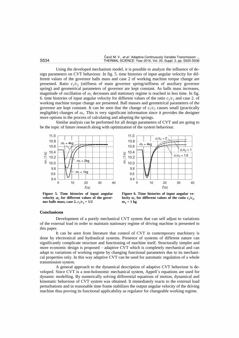
Using the developed mechanism model, it is possible to analyze the influence of de-
sign parameters on CVT behaviour. In fig. 5. time histories of input angular velocity for dif-
ferent values of the governor balls mass and case 2 of working machine torque change are
presented. Ratio c1/c2 (stiffness of main governor spring/stiffness of auxiliary governor
spring) and geometrical parameters of governor are kept constant. As balls mass increases,
magnitude of oscillation of 1 decreases and stationary regime is reached in less time. In fig.
6. time histories of input angular velocity for different values of the ratio c1/c2 and case 2. of
working machine torque change are presented. Ball masses and geometrical parameters of the
governor are kept constant. It can be seen that the change of c1/c2 causes small (practically
negligible) changes of 1. This is very significant information since it provides the designer
more options in the process of calculating and adopting the springs.
Similar analysis can be performed for all design parameters of CVT and are going to
be the topic of future research along with optimization of the system behaviour.
Conclusions
Development of a purely mechanical CVT system that can self adjust to variations
of the external load in order to maintain stationary regime of driving machine is presented in
this paper.
It can be seen from literature that control of CVT in contemporary machinery is
done by electronical and hydraulical systems. Presence of systems of different nature can
significantly complicate structure and functioning of machine itself. Structurally simpler and
more economic design is proposed – adaptive CVT which is completely mechanical and can
adapt to variations of working regime by changing functional parameters due to its mechani-
cal properties only. In this way adaptive CVT can be used for automatic regulation of a whole
transmission system.
A general approach to the dynamical description of adaptive CVT behaviour is de-
veloped. Since CVT is a non-holonomic mechanical system, Appell`s equations are used for
dynamic modelling. By numerically solving differential equations of motion, dynamical and
kinematic behaviour of CVT system was obtained. It immediately reacts to the external load
perturbations and in reasonable time frame stabilizes the output angular velocity of the driving
machine thus proving its functional applicability as regulator for changeable working regime.
Figure 6. Time histories of input angular ve-
locity 1 for different values of the ratio c1/c2, mT = 1 kg
Figure 5. Time histories of input angular
velocity 1 for different values of the gover-nor balls mass, case 2, c1/c2 = 1/2
ω1
[1/s
]
ω1
[1/s
]
t [s] t [s]
mT = 4kg
mT = 2kg
mT = 1kg
mT = 4kg
c1/c2 = 1/2
c1/c2 = 1
c1/c2 = 2

^avi}, M. V., et al.: Adaptive Continuously Variable Transmission ... THERMAL SCIENCE: Year 2016, Vol. 20, Suppl. 2, pp. S525-S536 S535
In further work, an extensive study of the CVT design parameters influence on its
characteristics and functioning has been intended. Based on the information that will be ob-
tained and dynamical model developed in this paper, an optimization of CVT design will be
performed as well.
Nomenclature
aCi – acceleration of the centre of mass Ci of body i
c1, c2 – spring coefficient of main and auxiliary spring, respectively
, , – position angle, angular velocity and an- gular acceleration of governor bar
ΔL1, ΔL2 – preload of main and auxiliary spring, respectively
i , i – angular and acceleration velocity of body i ξ, η, ζ, ξ, η, ζ, ξ, η, ζ – angular ac-
celerations, angular velocities and angles about axes of coordinate system rigidly connected to the body, its origin coincides with Ci
1, 2, 3, 4, 1, 2, 3, 4, 1, 2, 3, 4– an- gular position, angular velocity and angu-lar accelerations of elements 1, 2, 3 and 4, respectively
iGB1, iGB2 – transmission ratio of gearboxes 1 and 2, respectively
J1 – moment of inertia of input element 1 about its axis of rotation
J2 – moment of inertia of output element 2 about its axis of rotation
J3 – moment of inertia of element 3 about axis (normal to disc and passing through O3)
J3 – moment of inertia of element 3 about axis (lying in the disc plane and pass-ing through O3)
J4 – moment of inertia of element 4 about its axis of rotation
J6, J7 – moments of inertia of elements 6 and 7, respectively (reduced to shaft of input element 2)
JC – moment of inertia for axis through Ci
JEM – moment of inertia of electro motor (re- duced to shaft of input element 1)
JGB1 – moment of inertia of gear box 1 (reduced to shaft of input element 1)
JGB2 – moment of inertia of gear box 2 (reduc- ed to shaft of input element 2)
Jk – moment of inertia of governor’s slider (reduced to shaft of input element 2)
JWM – moment of inertia of working machine (reduced to shaft of output element 2)
L1, L2 – lengths of main and auxiliary spring, re- spectively
mi – mass of body i M1, M2 – moments on of input and output ele-
ments 1 and 2, respectively П1, П2 – potential energy of the springs , , – generalized coordinate, velocity and ac-
celeration Qv
* – generalized force
R1, R2 – radii of input and output half ball ele ments 1 and 2, respectively
R4 – radius of element 4 R3 – radius of element 3 S
* – energy of acceleration of complete sys-
tem S
*
i – energy of acceleration of body i S
*
i translation – energy of acceleration of the center of the mass Ci of the body i
S*
i rotation – energy of the acceleration of the body i in spherical motion about point Ci
t – time , , – speed, velocity and acceleration of the
governor slider
References
[1] Pronin, B. A., Revkov, G.A., Besstupenchatie Klinoremennie i Frikcionnie Peredachi (Variatori) (Step-less V-belt and Frictional Continuously Variable Transmissions (Variators), in Russian), Mashinostroe-nie, Moscow, USSR, 1967
[2] Brace, C., et al., The Compromise in Reducing Exhaust Emissions and Fuel Consumption from a Diesel CVT Power Train over Typical Usage Cycles, Proceedings, CVT’99, Eindhoven, The Netherlands, 1999, pp. 27-33
[3] Carbone, G., et al., Fuel Consumption of a Mid Class Vehicle with Infinitely Variable Transmission, SAE Transactions 2001 Journal of Engines, 110 (2002), 3, pp. 2472-2483
[4] Patterson, M., The Full Toroidal Variator in Theory and Practice, Torotrak Development Ltd., Proceed-ings, CVT’96, Yokohama, Japan, 1996, pp. 95-100
[5] Poulton, M. L., Fuel Efficient Car Technology, WIT Press, Computational Mechanics Publications, United Kingdom, 1997

^avi} M. V., et al.: Adaptive Continuously Variable Transmission ... S536 THERMAL SCIENCE: Year 2016, Vol. 20, Suppl. 2, pp. S525-S536
[6] ***, http://world.honda.com/automobile-technology/CVT/ [7] ***, http://www.nissan-global.com/PDF/tcvt_e.pdf [8] ***, http://www.audi.co.uk/audi-innovation/our-technologies/transmissions.html [9] Srivastava, N., Hakue, I., A Review on Belt and Chain Continuously Variable Transmissions: Dynamics
and Control, Mechanism and Machine Theory, 44 (2009), 1, pp. 19-241 [10] Fuchs, R., et al., The Making of the Full Toroidal Variator, JTEKT Engineering Journal, 106E (2009),
pp. 31-36 [11] Renius, K., Resch, R., Continuously Variable Tractor Transmissions, Proceedings, Agricultural Equip-
ment Technology Conference, Louisville, Ken., USA, 2005, pp. 1-37 [12] Miltenović, V., et al., Differential Planetary Transmission of Wind Turbine Continuously Variable
Transmission, Machine Design, 2 (2010), May, pp. 123-128 [13] Mangialardi, G., Automatically Regulated CVT in Wind Power Systems, Renewable Energy, 4 (1994),
3, pp. 299-310 [14] Verdonschot, M. J., Modeling and Control of Wind Turbines Using CVT, M. Sc. thesis, University of
Technology, Eindhoven, The Netherlands, 2009 [15] Sergeev, V. I., The Dynamics of Frontal Frictional Mechanism (Speed Variator), Journal of Machinery
Manufacture and Reliability, 43 (2014), 6, pp. 478-481 [16] Sergeev, V. I., Kinematics of Mechanisms with Rolling Pairs, Journal of Machinery Manufacture and
Reliability, 40 (2011), 4, pp. 313-318 [17] Ivanov, K., Tultaev, B., Toothed Continuously Variable Transmission – Industrial Realization, New
Trends in Mechanisms and Machine Science, Springer, Germany, 2013, pp. 329-335 [18] Ivanov, K., Theory of Gear Adaptive Transmission, American Journal of Mechanics and Application, 2
(2014), 1, pp. 5-12 [19] Zlokolica, M., et al., General Approach to the Dynamical Behavior of Power Transmission as Non-
holonomic System, Proceedings, International Conference on Motion and Power Transmissions MPT2009, Sendai, Japan, 2009, pp. 371-374
[20] Dobronarov, V. V., Osnovi Mehaniki Negolonomnih Sistem (Mechanics of Non-holonomic Systems, in Russian), Vissha Shkola, Moscow, USSR, 1970
Paper submitted: October 4, 2015 Paper revised: November 23, 2015 Paper accepted: December 30, 2015