Embed Size (px)
Citation preview
AD'-A254 097 DESIGNadPROTOTYPING (9lliIlhIIIIIl/IIIIIliIliiiiliii OF HARD REAL TIME SYSTEMS
Electronics Research Laboratory- - __University of California
Berkeley, CA 94720
Final Report ELECTE
June19 SmAU1992D-_" Principal Investigators
R.W. [email protected]
(415) 642-1779
A.R. NewtonA.L. Sangiovanni-Vincentelli
J.M. Rabaey
F-1 R.K BraytonE.A. Lee
D.G. Messerschmitt
_ SPONSORED BY-DEFE-NSE ADVANCED RESEARCH PROJECTS AGENCY
SPACE MONITORED BY. SPACE AND NAVAL WARFARE SYSTEMS COMMAND1UNDER CONTRACT No. N00039-88.C-0292 (TASK 5)
. 'is document has been approved 92-19865:.' t~r public release and sale; Its
a #sttibution is unlimited. I
9 2 7 3 01T2ELECTRONICS RESEARCH LABORATORY
College of EngineeringUniversity of California, Berkeley, CA 94720

0
7Ue views and conclusions in this document are those of the authors and should not be interree asrepresenting the official policies, either expressed or implied, of the Defense Advanced Research ProjectsAgency or the U.S. Government.

Table of Contents
CAD INFRASTRUCTURE AND TOOLS .................................................. 1
1.1 Massively Parallel Algorithms for Three-Dimensional DeviceSimulation (A. Sangiovanni-Vincentei) ......................................................... 1
1.2 Almost Periodic Fourier Transform ....................................................... 3
1.3 Finite-Time Theory of Simulated Annealing on Special EnergyLandscapes (A. Sangiovanni-VincenteUi) ........................................................ 4
1.4 Implementation of the DFT-based Quasi-Periodic Steady StateAnalysis in Spectre (A. Sangiovanni-Vincentelli) ............................................ 5
1.5 Generation of Analytical Models for Layout Interconnects (A.Sangiovanni-Vincentelli) .................................................................................. 7
1.6 A nalog Testing ....................................................................................... 7
1.7 Constraint Generation for Routing Analog Circuits .............................. 8
1.8 Logic Synthesis for Programmable Gate Arrays (AlbertoSangiovanni-Vicentelli) .................................................................................... 9
1.9 Development of the SIS (Sequential Interactive Synthesis System)(R .K . Brayton) .................................................................................................. 11
1.10 Retiming and Initialization of Finite State Machines (R.K. Bray-ton) .................................................................................................................... 12
1.11 Technology Mapping for Area and Delay (R.K. Brayton) .................... 12
1.12 Optimum and Heuristic Algorithms for Finite State MachineDecomposition and Partitioning (A.R. Newton) ............................................. 12
1. 13 A Unified Approach to the Decomposition and Re-decompositionof FSMs (A.R. Newton) ..................................................................................... 13
1.14 Testability Driven Decomposition of Large Finite State Machines(A .R . N ew ton) .................................................................................................... 14
1.15 Cache Management Techniques for Multiprocessors, with anEmphasis on VLSI Cad Applications (A.R. Newton) ................... 14
1.16 SLIP: System Level Interactive Partitioning (A.R. Newton) ............... 16
1.17 Applying Synthesis Techniques to Aid Simulation (A. R. Newton).............................................................. ... ................. ......e...e....•• ..° ...,.. ..... 1771.18 A Generalized Approach to the Constrained Cubical EmbeddingProblem (A .R. N ewton) .................................................................................... 181.19 Symbolic Encoding of High-Level Descriptions for Multi-LevelImplementations (A.R. Newton) ....................................................................... 19
1.20 Exploring Equivalent State Machines and State Assignment (A.R.

-2- 0
N ew ton) ............................................................................................................. 20
References ............................................................................................. 21
2. ARCHITECTURES AND APPLICATIONS .................. 25 0
2.1 VLSI ASIC and System for Hard Real-Time Tracking (R.W. Bro-dersen) ............................................................................................................... 25
2.2 A Real-Time, Flexible Image-Processing Printed Circuit Board(R.W . Brodersen) .............................................................................................. 26 6
2.3 Real Time Image Data Compression (R.W. Brodersen) ....................... 27
2.4 Programmable IC Digital Signal Processor with Self-Timed Inter-nal Processing Elements (R.W. Brodersen) ..................................................... 27
2.5 TADS: A Test Applicationm and Development System (R.W.Brodersen) ......................................................................................................... 29 0
2.6 Design Tools for Rapid Design of Oversampling A/D Converters(R.W . Brodersen) .............................................................................................. 29
2.7 Active-Word Processor for a Real-Time, Large-Vocabulary,Continuous-Speech Recognition System (R.W. Brodersen) ............... 30
2.8 Interface Board for the Robot Control System (R.W. Brodersen)• ................o,.,........................................... ........... .......e......*...*... ...e ..* ...* .,... .* 311
2.9 Design of Real-Time Systems with Application to Robotics (R.W.Brodersen) ......................................................................................................... 31
2.10 Backtrace Memory Processor for a Real-Time, Large-Vocabulary,Continuous-Speech Recognition System (R.W. Brodersen) ............... 32
2.11 ASIC's for Numerical Computations (R.W. Brodersen) ...................... 33
2.12 ASIC's for Inverse Kinematics (R.W. Brodersen) ................................ 33
2.13 A Programmable DSP for LagerIV (R.W. Brodersen) .......................... 34
2.14 Board-Level System Interfacing (R.W. Brodersen) .............................. 34
2.15 Wideband Digital Portable Communications (R.W. Brodersen) .......... 35
2.16 Oct2PCB Placement and Routing within LagerIV (R.W. Broder-sen) .................................................................................................................... 36
2.17 Techniques for Very Fast System Prototyping (J.M. Rabaey, R.W. 9Brodersen) ......................................................................................................... 362.18 Fast Prototyping of Video and Speech Systems (J.M. Rabaey) ............ 372.19 HYPER -- An Interactive Synthesis Environment for High-Performance Real-Time Applications (J.M. Rabaey) ................... 38
2.20 High-Quality Speech Coding for Portable Communications (J.M.R abaey) ............................................................................................................ 39
2.21 Partitioning DSP Algorithms onto Multiprocessors withConfigurable Interconnection (J.M. Rabaey) .................................................... 40
2.22 SMART: Switchable Multiprocessor Architecture with Real- •Time Support (J.M. Rabaey) ............................................................................. 402.23 Extended THOR (J.M. Rabaey) ............................................................ 41
-3-
2.24 Behavioral Transformations for the Synthesis of High-Performance DSP Systems (J.M. Rabaey) ....................................................... 42
2.25 Scheduling and Resource Allocation in the Design of High-Performance Digital Signal Processor (J.M. Rabaey) ................... 42
2.26 A Hardware Environment for Rapid Prototyping of DSP Systems(J.M . Rabaey) ................................................................................................... 43
2.27 Pulsar Signal Recovery (J.M. Rabaey) .................................................. 44
2.28 Frigg: A Simulation Environment for Multiple-Processor DSPHardware Development (E.A. Lee) ................................................................. 44
2.29 Heterogeneous Hardware Targets (E.A.Lee) ................... 45
2.30 Ptolemy: A Non-Dogmatic Third Generation SimulationEnvironment (E.A. Lee and D.G. Messerschmitt) ............................................ 45.
References ............................................................................................ 46
Accesion For'DT'C ,r7 - , .'-i~ - -NTIS CRP&I
DIIC TAB [2
Unanlouice-
Justification Li, , ............ ...............
B Y ....... .......Distibutio,
Av ia.j ' y " r.,-
Statement A per telecon John MachadoSPA WAR/Code 231Washington, DC 20363
NWW 8/17/92
1. CAD INFRASTRUCTURE AND TOOLS
1.1. Massively Parallel Algorithms for Three-Dimensional Device Simulation (A.Sangiovanni-VincenteUi)
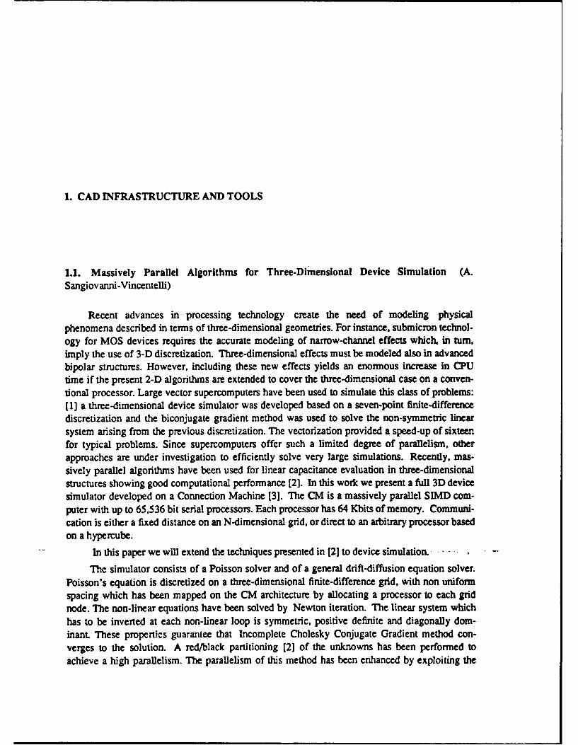
Recent advances in processing technology create the need of modeling physicalphenomena described in terms of three-dimensional geometries. For instance, submicron technol-ogy for MOS devices requires the accurate modeling of narrow-channel effects which, in turn,imply the use of 3-D discretization. Three-dimensional effects must be modeled also in advancedbipolar structures. However, including these new effects yields an enormous increase in CPUtime if the present 2-D algorithms are extended to cover the three-dimensional case on a conven-tional processor. Large vector supercomputers have been used to simulate this class of problems:[1] a three-dimensional device simulator was developed based on a seven-point finite-differencediscretization and the biconjugate gradient method was used to solve the non-symmetric linearsystem arising from the previous discretization. The vectorization provided a speed-up of sixteenfor typical problems. Since supercomputers offer such a limited degree of parallelism, otherapproaches are under investigation to efficiently solve very large simulations. Recently, mas-
sively parallel algorithms have been used for linear capacitance evaluation in three-dimensionalstructures showing good computational performance [2]. In this work we present a full 3D devicesimulator developed on a Connection Machine [3]. The CM is a massively parallel SJMD com-puter with up to 65,536 bit serial processors. Each processor has 64 Kbits of memory. Communi-cation is either a fixed distance on an N-dimensional grid, or direct to an arbitrary processor basedon a hypercube.
In this paper we will extend the techniques presented in [2] to device simulation.......
The simulator consists of a Poisson solver and of a general drift-diffusion equation solver.
Poisson's equation is discretized on a three-dimensional finite-difference grid, with non uniformspacing which has been mapped on the CM architecture by allocating a processor to each gridnode. The non-linear equations have been solved by Newton iteration. The linear system whichhas to be inverted at each non-linear loop is symmetric, positive definite and diagonally dom-inant. These properties guarantee that Incomplete Cholesky Conjugate Gradient method con-verges to the solution. A red/black partitioning [2] of the unknowns has been performed to
achieve a high parallelism. The parallelism of this method has been enhanced by exploiting the

2
processors which are idle during thepreconditioning phase. More specifically, defining the jaco-
bian matrix B = [IC] , + E,., where P1],. factorization of B for a proper r/b ordering, we com-
pute also the preconditioning for the associated b/r ordering. It is possible to show that this tech-nique reduces the maximum value of the entries of the error matrix E. This preconditioning doesnot requires any additional overhead, because the two solutions can be evaluated using the idleprocessors during the preconditioning phase. Table I shows the improvements in terms of itera-tions for the new method when compared with the standard one. The test structure is a 3D MOScapacitor on a uniform substrate (Na = 1016) and the number of grid nodes was 3120.
When the current flow is not negligible, the solution of the full set of drift-diffusion equa-tions is required. The Scharfetter-Gummel approach [4] is used to discretize the continuity equa-tions, the coupled Newton method to solve the non-linear system of algebraic equations, and theBiconjugate Gradient method [1] to invert the jacobian matrix. Since now there are three van-ables for each grid noue, as opposed to one for Poisson's equation, we use a two-level matrix, 0where the higher-level accounts for the interactions among adjacent nodes, while the (3x3)lower-level matrices are used to represent the interactions among the variables associated withthe same node. Following this approach, the Biconjugate Gradient method has been implementedreplacing each arithmetic operation by its matrix counterpart. The preconditioning scheme hasbeen formulated using a red/black partitioning of the high-level matrix. While alternative 0preconditioning approaches are now under evaluation, it is useful to consider the performance ofthe overall method for a simple diode polarized in high-injection regime. The diode hasNd = N. = 10- 16 (cm-3), the whole domain is a cube of 3g of side, and the n-doping profile ismodeled as a llp cube. The number of iterations required by the Newton method to reach conver-gence and the global number of iterations required by the BCG technique are shown in Table 2as a function of the applied voltage and of the number of grid nodes. The initialization of the vari-ables has been performed by a linear extrapolation from the two previous solutions. An impor-tant parameter to estimate the accuracy of the solution is given by the conservation of the currenteven at very low levels. We have simulated the same diode in reverse region (IV), evaluating thecurrents generated in the depleted region. The current conservation was achieved up to 5 digitsfor a current density of the order of 10-16 Amperei 2 using a relative convergence tolerance of10-' for the Newton method and 10-' for the BCG. Our preliminary measurements lead us to
expect a performance of 700 Mflops on a fully configured Connection Machine.
Bias Step Non-lin. It. I4 Av,. 00.0 9 202 155
0.1 3 63 47
0.2 3 155 45
0.3 3 60 47
Table 1: Comparison of the standard iteration with the new one.
3
1.2. Almost Periodic Fourier Transform
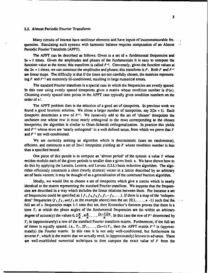
Many circuits of interest have nonlinear elements and have inputs of incommensurable fre-quencies. Simulating such systems with harmonic balance requires computation of an AlmostPeriodic Fourier Transform (APFT).
The APFT can be described as follows: Given is a set of n fundamental frequencies and2n + 1 times. Given the amplitudes and phases of the fundamentals it is easy to compute thefunction value at the times; this transform is called F-'. Conversely, given the function values atthe 2n + I times, we can construct the amplitudes and phases; this transform is F. Both F and F-1are linear maps. The difficulty is that if the times are not carefully chosen, the matrices represent-ing F and F-1 are extremely il-conditioned, resulting in large numerical errors.
The standard Fourier transform is a special case in which the frequencies are evenly spaced.In this case using evenly spaced timepoints gives a matrix whose condition number is 0(n).Choosing evenly spaced time points in the APFT case typically gives condition numbers on theorder of n !.
The APFT problem then is the selection of a good set of timepoints. In previous work wefound a good heuristic solution. We chose a larger number of timepoints, say 2(2n + 1). Eachtimepoint determines a row of F-'. We iteratively add to the set of 'chosen' timepoints theunchosen one whose row is most nearly orthogonal to the rows corresponding to the chosentimepoints; the algorithm is similar to Gram-Schmidt orthogonalization. In practice this yieldsand F-' whose rows are 'nearly orthogonal' in a well-defined sense, from which we prove that Fand F-' are well-conditioned.
We are currently seeking an algorithm which is deterministic (uses no randomness),efficient, and constructs a set of 2n+l timepoints yielding an F whose condition number is lessthan a specified bound.
One piece of this puzzle is to compute an 'almost period' of the system: a value T whoseresidue modulo each of the given periods is smaller than a given limit E. We have shown how todo this by applying the Lenstra, Lenstra, and Lovasz (LLL) basis reduction algorithm. The algo-rithm efficiently constructs a short (nearly shortest) vector in a lattice described by an arbitraryset of basis vectors; it may be thought of as a generalization of the continued fraction algorithm.
Ideally. we would like to choose a set of timepoints which give a matrix which is nearlyidentical to the matrix representing the standard Fourier transform. We suppose that the frequen-cies are described in a way which includes the linear relations between them. For instance a setof frequencies could be specified as (f .2zf.f.f,,flI-f'2 .... ). If there is a map of the 'indepen-dent' frequencies (f,.f and f 3 in the example above) into the set {0,1 ... ,n -1) such that the.full set of n frequencies maps 1-1 onto that set, then Kronecker's theorem proves that there is atime T, at which the phase angles of the fundamental frequencies are (to within an arbitrarydegree of accuracy) the values 0, 2.1, 4.1...., (,-1)2n. In this case the row ofF' determined byT, is (approximately) a row of the standard Fourier transform matrix. Furthermore, if the full setof times is equally spaced, i.e., T, ,2T, . . . , (2n+l) TI, then the APFT matrix F-' is (approxi-mately) the Fourier matrix. In this case it is not only well-conditioned, but furthermore itsinverse F. which is the matrix that we actually need, is (approximately) known in advance. Thereare well-established numerical techniques to then compute the exact value of F from the
4
constructed F-1.
This leaves us with the two fundamental problems on which we are now focusing.
First: does a 1-1 map from the set of frequencies to (0..... n-1I exist? If so, how do wefind it? And if not, what do we do next?
Second, how do we find the value Ti whose existence is guaranteed by Kronecker'stheorem?
The first question appears to be essentially combinatorial in nature, and we do not currentlyhave a good approach to solving it.
The second question may be related to the problem of finding an almost period, which wehave solved as described above. For example, in some cases using T, = T / (2n +1) works. Inother cases it is possible to reapply the LLL algorithm to compute an acceptable Ti. Thus there issome promise to this technique, though we do not know how to solve the general case.
1.3. Finite-Time Theory of Simulated Annealing on Special Energy Landscapes (A.Sangiovanni-Vincentelli)
The best theoretical results on simulated annealing apply to arbitrary spaces, includingthose for NP-hard problems, and are necessarily somewhat weak. In practice, the 'coolingschedules' used in annealing are more rapid than those analyzed by the theory, and the resultsobtained are much better than theory would predict. The strength of the practical results, com-bined with the fact that it is easy to construct problems on which annealing will not work well,means that problems encountered in practice have special properties of which annealing takesadvantage. Thus we take a two-pronged approach: studying properties of energy landscapes ofreal-world problems; and analyzing the behavior of annealing on landscapes with given proper-ties.
We have observed many fractal properties of combinatorial problems, focusing on place-ment problems. In particular, the sequence of energies observed over time is a Brownian or frac-tional Brownian motion (fBm). We have proved that a random walk on a fractal landscape pro-duces such fBm 'energy trajectories', and we conjecture that this mechanism is responsible.Also, direct sampling of points in the landscape shows an approximate power-law relationbetween distance and energy difference. Such a relation is a natural extension of the definition offractalness in Euclidean space (the landscapes of interest do not lie in Euclidean space).
Most recently we have studied a class of mathematically defined deterministic self-affinefractal energy landscapes on the reals. In this limited domain rigorous results can be derivedusing the tools of rapidly mixing Markov chains.
In particular it is proved that using a geometric cooling schedule, the expected energydifference between the state found by annealing and a true global minimum decreases approxi-mately as a (negative) power of the total time spent annealing. The power itself depends onparameters of the problem instance.
In this I -dimensional case, random sampling obeys a power law like that holding for 0annealing, and random sampling may even be faster (depending on the problem instance). But
0

5
for higher-dimensional fractals the speed of annealing is basically unchanged while that of ran-dom sampling decreases dramatically. The combinatorial spaces of practical interest do not havea well defined 'dimension' but do have many characteristics of very high-dimensional spaces,making these results particularly relevant.
These am dramatic new results. Previous formal studies of annealing have required that thetime spent be exponential in the problem size, which is unrealistic. In this case the time ispower-law in the 'quality' of result desired, and polynomial in D (for a D-dimensional fractal).Depending on whether range-limiting is employed, the time may be polynomial or exponential inthe log size of one 'side' of the D-cube.
In short, the theoretical analysis performed yields strong results for the restricted (but webelieve relevant) class to which it applies. It does so using a methodology which reflects what wethink to be the way annealing functions in practice.
We hope to extend these results to random fractals, which will require developing a com-pletely new set of mathematical tools. We also plan to use the theoretical analysis to guidefurther examination of practical problems, and ultimately to construct efficient annealingschedules and estimate their performance.
1.4. Implementation of the DFT-based Quasi-Periodic Steady State Analysis In Spectre (A.Sangiovanni-Vincenteli)
Spectre 15) is a harmonic balance simulator for analog and microwave circuits. It analyzesnonlinear analog circuits using the harmonic balance technique. Linear devices can be evaluateddirectly in the frequency domain. Nonlinear devices are in general impossible to evaluate in thefrequency domain directly; therefore, the excitation spectra of a nonlinear device is firsttransformed into time domain. The response is then evaluated in the time domain andtransformed back to the frequency domain. Currently, Spectre uses Discrete Fourier Transforms,and hence Fast Fourier Transforms, to convert periodic signals between time and frequencydomain. For quasiperiodic signals, a special transform ( the Almost Periodic FT [6,7]) is used toperform the conversions.
When the nonlinearities in the devices are algebraic, the coefficients of the sinusoids are fre-quency independent. Thus, for the purposes of evaluating the nonlinear devices, the actual funda-mental frequencies are of no importance and can be chosen freely. In particular, the fundamentalfrequencies can be chosen to be multiples of some arbitrary frequency so that the resulting sig-nals will be periodic, and DFT can be used. These artificially chosen fundamental frequencies arenot actually used in the harmonic balance calculations. They are used only to determine in whichorder to place the terms in the spectra. In other words, we are only interested in the correspon-dence (mapping) between quasiperiodic and periodic harmonic indices.
In order to make computation involving quasiperiodic signals tractable, we need to truncatethe frequencies into a finite set. The box and diamond truncation methods are two popular trun-cation methods. With the box truncation, only the first H harmonics of each fundamental fre-quency are considered. The diamond truncation limits the absolute sum of the indices of eachfundamental frequency to be less than or equal to H. Currently Spectre only considers two
6
fundamental frequencies.
For a set of frequencies coming from a box truncation, we havew I w=klI ()+k2(X2);OklSH .k21 9H2,kI*Oifk2<O the correspondence betweenquasiperiodic and periodic harmonic indices for this particular truncation method iskf(2H2+1)ikl+k2 (1)
For a set of frequencies obtained with a "diamond" truncation,w I w=kl (l)+k2(2); Ikil + lk21 .H,kl+k2>=O,kl !=k2ifk2>O
k=(H+l)kl+Hk2 (2)
is the mapping equation.
The users can specify a specific truncation scheme by specifying three parameters: HI, H2,and H, where
IkIl <HI Ik21 <H2 IkIl + Ik21<H
These constraints result in a combination of box and diamond truncation. In order to usethe above equations to perform mapping from kl, k2 to k, we first expand the set of frequenciesto its nearest box or diamond truncation whichever is smaller. Next, we used either equation (1)or (2) to map the quasiperiodic harmonic indices, kI and k2 into their corresponding periodicindices k, and construct the spectra. In order to use FF1, the size of the spectra has to be a powerof 2. Therefore, sometimes we would need to extend the size of spectra further to meet therequirement.
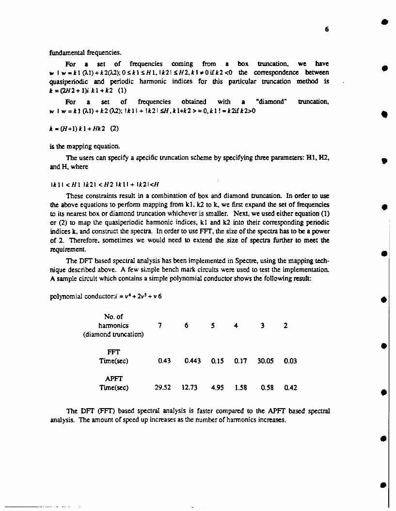
The DFT based spectral analysis has been implemented in Spectre, using the mapping tech-nique described above. A few simple bench mark circuits were used to test the implementation.A sample circuit which contains a simple polynomial conductor shows the following result:
polynomial conductor.i =V4 + 2v + v 6
No. ofharmonics 7 6 5 4 3 2
(diamond truncation)
FFrTime(sec) 0.43 0.443 0.15 0.17 30.05 0.03
APFTTime(sec) 29.52 12.73 4.95 1.58 0.58 0.42
The DFT (FFT) based spectral analysis is faster compared to the APFT based spectralanalysis. The amount of speed up increases as the number of harmonics increases.

7
1.5. Generation of Analytical Models for Layout Interconnects (A. Sangiovanni-Vincentelli)
As the scale of integration and speed requirements of integrated circuits increase, accuratemodelling of both on-chip and off-chip interconnects becomes necessary. As the widths of inter-connection lines are scaled down, the thickness is either kept constant or scaled by a muchsmaller factor to limit line resistance. As a result of this, the fringing and sidewall effects dom-inate the interconnect capacitances, causing gross error in estimation, if parallel-plate approxima-tion is used to compute line-to-ground and crossover capacitances. Also, shrinking widths of linesand increasing ratio of thickness to separation between lines increase tremendously the couplingcapacitance between two adjacent parallel lines as a fraction of the total capacitance of each line.This makes estimation of coupling capacitances between adjacent lines indispensable for today'sVLSIs.
Since the time constants associated with interconnects scale by a much smaller factor thanthose of devices, they are becoming increasingly significant in determining the speed of digitalsystems. At high speeds of operation, some of the interconnects act like transmission lines, andmatching considerations become important in the design process. Moreover, when very aggres-sive design rules are employed, stray coupling can cause the logic state of a line to change due toswitching of adjacent lines. In analog and mixed analog-digital circuits, needless to mention, per-formance can be extremely sensitive to interconnect parameters. All these factors combined havemade interconnect modelling an active area of research.
Analytical expressions are available for modelling some simple configurations. However,one may encounter very complicated configurations in the layout for which closed form expres-sions are not known for modelling purposes. Numerical methods based on finite-difference,finite-element or integral-equation techniques can be employed to extract the desired electricalparameters (lumped or distributed). These methods solve Maxwell's equations in some form, andusually incur very high computational cost. Hence, there is a need for analytical expressionswhich can be used by CAD tools for fast extraction of large layouts. Such expressions will alsoprovide useful insight to circuit and layout designers.
An experimental program has been developed which can generate analytical models forcapacitances (line-to-ground and line-to-line) in some specific configurations by performing aseries of accurate numerical simulations. The configurations considered right now are (a) singleline, (b) adjacent parallel lines, and (c) crossing lines. The models are being used in the routingof analog circuits.
1.6. Analog Testing
In this project we aim to reduce production testing time by designing efficient test sets. Asis done in digital testing, the test sets we design will be intended to detect the faults that are likelyto happen in practice. Therefore, we base our test set design on a fault model developed forestimating yield in fabrication, where faults are characterized as either catastrophic or parametric.It has been shown in previous work that catastrophic faults are relatively easy to detect in analogcircuits. Typically a few ac and dc tests are required. Consequently, most of production testing
M I.
8
time is spent attempting to detect parametric faults by verifying all of a circuit's specifications.As a result, any major reduction in testing ime should come from reducing the number ofspecification tests !hat need to be performed. In addition, since testing is terminated upon the firstfailure of a test, an optimal ordering of tests can further reduce testing time.
To identify unnecessary specification tests and optimally order the remaining tests, wtbegin with a statistical description of parameter fluctuations in fabrication. We add specificationtests to the set of optimally ordered tests one by one by looking at fault coverages of various sub-sets if tests. As tests are added, the current fault coverage of the set is determined, and the testset is complete when sufficient fault coverage has been reached.
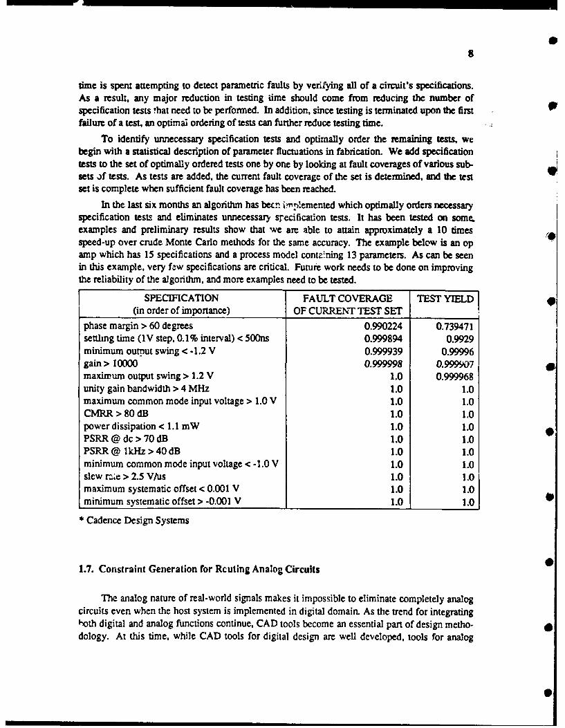
In the last six months an algorithm has becn i:,mIemented which optimally orders necessaryspecification tests and eliminates unnecessary sTecification tests. It has been tested on some.examples and preliminary results show that we are able to attain approximately a 10 timesspeed-up over crude Monte Carlo methods for the same accuracy. The example below is an opamp which has 15 specifications and a process model cont.-ning 13 parameters. As can be seenin this example, very faw specifications are critical. Future work needs to be done on improvingthe reliability of the algorithm, and more examples need to be tested.
SPECIFICATION FAULT COVERAGE TEST YIELD(in order of importance) OF CURRENT TEST SET
phase margin > 60 degrees 0.990224 0.739471settling time (IV step, 0.1% interval) < 5OOns 0.999894 0.9929minimum output swing < -1.2 V 0.999939 0.99996gain> 10000 0.999998 0.999907maxinrum output swing > 1.2 V 1.0 0.999968unity gain bandwidth > 4 MHz 1.0 1.0maximum common mode input voltage > 1.0 V 1.0 1.0CMRR > 80 dB 1.0 1.0power dissipation < 1.1 mW 1.0 1.0PSRR @ dc > 70 dB 1.0 1.0PSRR @ kHz > 40 dB 1.0 1.0minimum common mode input voltage < -1.0 V 1.0 1.0slew rae > 2.5 V/us 1.0 1.0maximum systematic offset < 0.001 V 1.0 1.0minimum systematic offset > -0.001 V 1.0 1.0 0
Cadence Design Systems
1.7. Constraint Generation for Rcuting Analog Circuits
The analog nature of real-world signals makes it impossible to eliminate completely analogcircuits even when the host system is implemented in digital domain. As the trend for integratinghoth digital and analog functions continue, CAD tools become an essential part of design metho-dology. At this time, while CAD tools for digital design are well developed, tools for analog
S

9
design are still inadequate for improving design productivity. Also, at very high frequencies ofoperation, since digital technology has not matured, analog processing of signals is widely used.Although simulation and optimization tools are used by analog designers in the electrical designphase, one is yet to see use of general purpose CAD tools for layout design. Since performance ofanalog circuits can be very sensitive to stray effects, manual layout is time consuming and ermi-prone.
Layout of analog circuits is usually designed by designers in an iterative fashion. In eachpass, after the layout is designed, all the layout parasitics are extracted and the circuit is simulatedto check if performance specifications are met. If they are not met, possible trouble spots in thelayout are "guessed," some changes made to the layout, and the process repeated. This is a highlyinefficient approach, which can give rise to a large number of time consuming iterations.
We follow a novel constraint-based approach[8] for automating analog layout, both place-ment and routing, although presently we are concentrating on routing. Analog routing is con-sidered as much more than a path-connection problem. In the first phase, critical layout parasiticsare detected using sensitivity analysis[9]. Then a set of constraints is generated on these criticalparasitics to ensure that circuit performance degradation remains within some specified limit.These constraints can then be used to drive the autorouter. This results in a high probability thatperformance specifications be met in the very first pass of routing. The parasitic constrants are oftwo types; bounding constraints and matching constraints . Since there can be many possiblecombinations of constraints which meet performance specifications, a unique algorithm is used togenerate a set of constraints which maximize the flexibility of the router.
The program PARCAR (a parasitic constraint generator for analog routing) developed by usgenerates constraints on capacitances (both net-to-net and net-to-ground) for a given set of perfor-mance constraints. Interface programs have been developed for the simulators SPICE3 andSWAP to automatically obtain sensitivities with respect to all possible routing capacitanceswhich may possibly exist in the layout. These sensitivities are fed to PARCAR for generatingconstraints. PARCAR is being interfaced to the area router ROAD and the channel routerROADRUNNER.
1.8. Logic Synthesis for Programmable Gate Arrays (Albeno Sangiovanni-Vincentelli)
Programmable gate arrays (PGA's) are becoming increasingly important architectures forrapid system prototyping. One common feature of such architectures is the presence of a repeatedarray of identical logic blocks. A logic block is a versatile configuration of logic elements whichcan be programmed by the user.
With the growing complexity of the logic circuits that can be packed on a PGA, it becomesnecessary to have automatic tools that map logic functions onto these architectures. A simpleapplication of the logic synthesis techniques used for semi-custom, cell-based architectures gen-erally does not yield a satisfactory result and may be totally inadequate for such architectures. Weare investigating the problem of combinational logic synthesis for two interesting and popularprogrammable gate array architectures: a RAM based architecture (Xilinx) and a multiplexorbased one (Actel). We address the problem of synthesizing a set of Boolean equations using these

10
architectures such that minimum number of logic blocks are used.
In the Xilinr architecture, a basic block can implement any logic function of up to five vari-ables. The algorithm has two main steps: decomposition and covering. Decomposition is appliedon those functions which have more than five inputs. Various decomposition techniques are usedto obtain a network in which all nodes have at most five fanins, e.g. classical decomposition tech-niques like Karp-Roth decomposition are investigated and compared with kernel extraction basedon support of the functions. After decomposition, the new network may have some functionswhich can be realized by one basic block. So, covering methods are used to reduce the number of 9basic blocks needed for the network. We use exact covering formulation and also some heuristicsto solve this otherwise intractable problem.
In the Actel architecture, the basic block is a configuration of 2-to-I multiplexors. Ourmethod of synthesis is similar to the one employed in MISII. However, guided by the architec-ture, we choose a different representation of subject-graph and pattem-graphs. We capture the 0gates in the library by a very small pattern-set. After covering the subject-graphs by pattern-graphs, we use an iterative-improvement phase which uses collapse and decompose operations toimprove the result.
The results for both the architectures, as given in the following tables, are encouraging. Ourresults are given under column mis-pga. For Actel architecture, we compare our results withMISII results, whereas for Xilinx, we compare with results obtained from industry. Area is interms of number of basic blocks.
XILINX
example no. nodes mis-pga ind. results
(init.) Area time Area
l0bitreg 20 10 6.9 11
lOcount 126 23 154.2 19
180degc 146 21 74.5 34
3to8dmux 101 30 81.1 25
4-16dec 70 12 57.5 18
4cnt 66 17 35.0 10
8bappreg 141 27 64.9 27
8count 138 20 57.7 29
9bcasc2 135 34 1028.9 45
99bcasc2 133 29 91.9 42
arbiter 146 21 73.3 13

11
ACTEL
example MISII mis-pga
Area time Area time
fSlm 52 21.5 50 59.7
bw 80 46.7 65 82.0
rot 310 108 3292 497.4
5xpl 52 19.5 46 43.2
c499 174 81.7 166 61.0Cc1908 189 104.99 185 3258888.6
C5315 732 353 666 1865.3
It should be mentioned here that the algorithms described here are general: e.g. the algo-rithms for Xilinx architecture would work for any architecture in which the basic block imple-ments a function of n variables, n >= 2.
As future work, we plan to look into minimizing the delay through the critical path. Exten-sion to sequential circuits is also planned. It is hoped that such a tool will enable evaluations ofdifferent PGA architectures from synthesis point of view and result in design of better architec-tures.
1.9. Development of the SIS (Sequential Interactive Synthesis System) (R.K. Brayton)
Several critical issues regarding the internal data structures and the interchange formatneeded to be resolved. In particular, an extended version of BLIF (Berkeley Logic InterchangeFormat) was designed and is supported by SIS. (Done by S. Malik, Tzvi Ben-Tzur and K. J.Singh). This extended format permits specification of sequential elements (latches), timing infor-mation (clocking schemes) and state transition diagrams along with gates to represent digitallogic. A reader and writer for this format was written and incorporated in SIS.
Area optimization using retiming and resynthesis ideas (developed earlier last year) wasimplemented as part of SIS. Surprisingly, the area improvements obtained using these techniqueswere negligible. This was shown to be a possible result of limitations of existing combinational.logic optimization tools as well as being an inherent characteristic of the logical nature of some.classes of circuitF These results were presented along with their analysis at HICSS 90 [10].
Performance optimization using retiming and resynthesis was satisfactorily tackled (workdone by S. Malik and K. J. Singh). We considered the problem of redesigning a given pipelinedcircuit to meet a required cycle time. We demonstrate how the pipelined circuit can betransformed to a combinational circuit and show that solving a performance optimization prob-lem for this combinational circuit is both necessary and sufficient for solving the performanceoptimization problem for the pipelined circuit. This is significant in two ways. Firstly, it showsthat all known (as well as to be developed) ideas in combinational performance optimization can
12
be used in pipeline performance optimization. Second, it shows that these are enough, i.e., weneed not consider special techniques for pipelined circuits.
1.10. Retiming and Initialization of Finite State Machines (R.K. Brayton)
Retiming is a general and powerful technique to perform delay or area optimization ofsequential circuits. When sequential circuits are specified with an initial state, it is necessary tomaintain the initial state across retimings. We have developed and implemented in SIS a simpleand elegant method to perform this computation. If the initial state of the circuit is contained in acycle of state transitions, our algorithm does not require any modification of the logic of the cir-cuit, at the difference of previous approaches. For finite state machines, it is a simple matter dur-ing state assignment to make sure that the initial state is contained in a cycle of transitions if it isnot already the case. This can be achieved at little or no cost in final circuit area. Once this condi-tion is satisfied, initial states can be maintained across retimings with no need for costly statetransition graph extractions, backtracking searches, or logic dupliation.[l I]
4
1.11. Technology Mapping for Area and Delay (R.K. Brayton)
Technology mapping is the process of mapping a logic network onto a set of predefined andcharacterized library gates. Most of the early work in this area has focused on minimizing circuitarea, and only a small set of optimization techniques have been available for minimizing circuitdelay. We have developed and implemented several new algorithms to perform delay minimiza-tion at a moderate cost in area, and we have obtained encouraging results (average speedups of43% for a 14% increase in circuit area). These algorithms have been incorporated in the latestrelease of misll (version 2.2).
The basis of our approach is to decompose circuits in networks of trees, and use efficientalgorithms to implement each tree separately. A similar decomposition was used in previouswork (e.g. [12]). The main originality of our work is to incorporate within the same frameworktwo kinds of trees: fanin trees, which implement the logic of the circuit, and fanout trees, whichdistribute the output signals of fanin trees to their destinations. In the present implementation,fanin tree optimization and fanout tree optimization are done independently. We are currentlyexperimenting with the best way to integrate these two optimizations.
1.12. Optimum and Heuristic Algorithms for Finite State Machine Decomposition and Par.titioning (A.R. Newton)
Techniques have been proposed in the past[15,16,17,18] for various types of finite statemachine (FSM) decomposition that use the number of states or edges in the decomposed circuitsas the cost function to be optimized. These measures are not reflective of the true logic

13
complexity of the decomposed circuits. These methods have been mainly heuristic in nature andoffer limited guarantees as to the quality of the decomposition. In this work[14], optimum andheuristic algorithms for the general decomposition of FSMs have been developed such that thesum total of the number of product terms in the one-hot coded and logic minimized submachines ,+,,.is minimum or minimal. This cost function is much more reflective of the area of an optimallysate-assigned and minimized submachine than the number of states/edges in the submachine.The problem of optimum two-way FSM decomposition has been formulated as one of symbolic-output partitioning and has been shown to be an easier problem than optimum state assignmenmA procedure of constrained prime-implicant generation and covering has been described thatrepresents an optimum FSM decomposition algorithm, under the specified cost function. Exactprocedures are not viable for large problem instances. A novel iterative optimization strategy ofsymbolic-implicant expansion and reduction, modified from two-level Boolean minimizers, thatrepresents a heuristic algorithm based on the exact procedure has also been developed. Reductionand expansion are performed on functions with symbolic, rather than binary-valued outputs. Theheuristic procedure can be used for problems of any size. Preliminary experimental results havebeen presented that illustrate both the efficacy of the proposed algorithms and the validity of theselected cost function.
1.13. A Unified Approach to the Decomposition and Re-decomposition of FSMs (A.R.Newton)
A unified framework and associated algorithms for the optimal decomposition and re-decomposition of sequential machines have been developed. This framework allows for a uni-form treatment of parallel, cascade and general decomposition topologies, operating at the StateTransition Graph (STG) level, while targeting a cost function that is close to the eventual logicimplementation.
Previous work in decomposition has targeted specific decomposition topologies[20,21,23].In this paper[19), the decomposition problem has been formulated as one of implicant coveringwith associated constraints. An optimum covering corresponds to an optimum decomposition. Ithas been shown in this work that two-way or multi-way, parallel, cascade or general decomposi-tion topologies can be targeted, simply by changing the constraints in the covering step. The rela-tionship of this work to preserved partitions and covers, traditionally used in parallel and cascadedecomposition has been indicated.
In many cases, an initial decomposition is specified as a starting point. Attempting toflatten a set of interacting circuits into a single lumped STG could require astronomical amountsof CPU time and memory. Memory and CPU time efficient re-decomposition algorithms thatoperate on distributed-style specifications and which are more global in nature than thosepresented in the past have been developed [22]. Arbitrary, interacting sequential circuits can beoptimized for area and performance by iteratively applying re-decomposition algorithms acrosslatch boundaries.

14
1.14. Testability Driven Decomposition of Large Finite State Machines (A.R. Newton)
The synthesis of controllers in the form of interacting finite state machines (FSMs) canresult in improved performance and smaller area. In this work, we address sequential testabilityaspects in the decomposition of FSMs.
In this work, testability-driven decomposition techniques have been presented that realizecontrollers as FSM networks consisting of mutually interacting submachines which are fullytestable for all single stuck-at faults without requiring direct access to the memory elements.Constrained decomposition techniques for the synthesis of fully and easily testable decomposedFSM networks have been described. Subsequently, an exhaustive classification of redundantfaults that can occur in a single FSM embedded in a network has been presented. Associatingeach class of these redundant faults with a don't care set, an optimal decomposition technique hasbeen described that synthesizes controllers as irredundant FSM networks with no area overheadby exploiting these don't cares optimally.
A FSM network can be flattened into a single State Graph and made fully testable usingpreviously proposed synthesis techniques[24,25,. However, when dealing with a large, lumpedFSM the don't care set under which the synthesis has to be optimal could be huge. Also, if thegiven initial representation is distributed, flattening it into a single lumped STG can require astro-nomical amounts of memory and CPU time.
It has been shown in this work that when a circuit is being implemented as an interconnec-tion of FSMs, the required don't care set in an optimal synthesis procedure can be heavily pruned.Partitioning of logic serves to filter out the part of the don't care set which is not useful. The newsynthesis procedure operates on a distributed-style representation of interacting STGs, which isconsiderably more compact than a lumped representation, carrying out a series of local analyses.This decomposition-based optimal synthesis technique is significantly more efficient, both interms of memory and CPU time usage than previously proposed optimal synthesis techniques. Itis, therefore, viable for circuits of greater size.
1.15. Cache Management Techniques for Multiprocessors, with an Emphasis on VLSICAD Applications" (A.R. Newton)
0
General purpose multiple instruction stream, multiple data stream (MIMD) multiprocessorsoffer an attractive means of accelerating many computationally intensive tasks that arise in VLSICAD systems; examples of such tasks include circuit simulation, logic simulation, placement,routing, design rule checking and fault simulation. MIMD multiprocessors are attractive becausethey are a general purpose solution that can also be exploited as high performance multipro- 0grammed computers. This is in contrast to special purpose CAD accelerators that only supportsingle tasks such as logic simulation.
The particular class of shared-bus, shared-memory multiprocessors has gained commercialacceptance with offerings by Sequent, Encore and others. These machines offer high perfor-mance at reduced cost for applications with modest amounts of exploitable parallism. Byefficiently supporting the shared memory programming paradigm at the hardware level, these
0

is
machines are usually much easier to program than those supporting message passing because theprogrammer does not have to worry about distributing data across multiple memories. Sharedmemory is especially attractive for programming CAD applications because it is often unclearhow to efficiently map the problem at hand into a set of message passing processes.
The success of shared-bus multiprocessors is largely due to the efficient caching techniquesmade possible because of the shared bus [26]. Effective caching techniques are important in mul-tiprocessor design because the provision of a cache at each processor masks the often severeaccess delay to main memory through an interconnection network. Unfortunately, computerswith two or more caches require techniques for ensuring that the caches remain consistent: allchanges to a piece of data must be reflected in all cached copies. It is now fairly well-understoodhow to enforce cache consistency in shared-bus multiprocessors by exploiting their broadcastcapabilities [27]. Unfortunately, shared-bus architectures support relatively few processors (prob-ably 50 or less), and it is unclear how to enforce consistency in more scaleable, non-bus architec-tures; this is the problem that we address in this research.
Cache consistency methods proposed to date maybe divided into four classes: those inwhich shared writeable data is uncached, "snooping" protocols (for shared-bus systems), directoryschemes, and software assisted techniques [28]; the first three classes are categorized as hardwarebased techniques. Hardware techniques enforce consistency in a manner that requires no specialcache control instructions in program object code. Software techniques enforce consistency byinserting cache control instructions in object code at compile time. Since compilers generallyhave more information about the future behavior of a program than does the hardware at run time,software methods offer potentially better performance in terms of reduced average access timeand network traffic. Several large, non-bus shared memory multiprocessor designs--the NewYork University Ultracomputer [29], IBM RP3 prototype [30], and University Ilinois Cedarmachine [3l]--have dealt with the consistency problem using software methods. Only recentlyhas work been reported on the investigation of hardware coherence methods for large non-busmachines [,32,33,34,35]. In most of these cases the methods proposed deal with specific architec-tures based on collections of buses connected in meshes, cubes or trees. In addition, few resultshave been reported characterizing the behaviour of parallel programs running on large numbers ofprocessors; most machine designs have been based on analytic models.
This project is an investigation of the performance of cache consistency schemes suitablefor large scale shared memory multiprocessors. It began with a comparison of three schemesusing execution driven simulation of three parallel CAD programs. The first coherence, schemewas simple: shared-writeable data is not cached. This scheme provided a reference point for thetwo others. The second scheme was a sectored variation of that published by Censier and Feau-trier [36] in which tags are associated with each block of main memory to record all caches hav-ing copies; whenever a processor writes to shared-writeable data all other copies are invalidatedusing the data stored in the tags. While this method permits shared-writeable data to be cached,the additional memory required for tags and the additional network traffic required for invalida-tions may be excessive. The third scheme was novel in that it permitted the assignment of data tophysical main memory locations to change dynamically. It required main memory to be distri-buted among the processors and handled it as if the distributed pieces were caches themselves.Since main memory is usually an order of magnitude larger than the aggregate cache memory,network traffic may be reduced if local memory hit rates improve and consistency traffic is low.
16
The comparison demonstrated three principal results. First, for the benchmarks consideredthe number of references to shared-writeable data is sufficiently high to justify the caching ofshared-writeable data; significant reductions in average memory access time and network trafficwere obtained for the second and third coherence schemes relative to the first. Second, the com-ponent of network traffic due to sharing and synchronization dominated the component due tonormal cache misses. This showed that the reduction in normal miss traffic permitted by thelarger effective cache size of the third scheme had little impact on improving performance.Third, the simulations showed that although the sectored version of Censier and Feautrier'sscheme provided substantial performance improvement over the first scheme, the large blocksizes required to minimize tag overhead introduced an excessive amount of false sharing.
The initial evaluation has been extended by considering the use of tag caches as a way toreduce tag overhead while minimizing false sharing. In a tag caching scheme, tags are not associ-ated with each block of main memory but are stored in an associative memory indexed by blockaddress. This permits a much smaller number of tags at the expense of a more complex mainmemory controller. Since the number of tags is much smaller than the number of main memoryblocks in such a scheme, it is necessary to prematurely displace shared data from caches to get afree tag. preliminary results [37] on the effect of various tag cache sizes on network traffic andaverage access time show that Censier and Feaurier's directory method performs as well with atag cache as with a full directory. Preliminary implementation considerations suggest that a tagcache can be implemented with the same low cost dynamic RAM as data memory.
This work is currently being extended by evaluating more realistic network models, includ-ing direct and indirect binary cubes, and cubes and trees of busses. Future work will also addressthe effectiveness of combining as a technique for reducing the significant performance degrada-tion caused by synchronization. An initial evaluation of alternatives will use approximate queue-ing models, and will require the development of techniques that model synchronization. Themost promising alternatives will then be evaluated using detailed simulations. This work willalso be extended by acquiring more benchmark programs and by considering larger numbers ofprocessors.
1.16. SLIP: System Level Interactive Partitioning (A.R. Newton)
Large electronic systems are usually constructed as a hierarchy of physical components,such as backplanes, boards, chip, and transistors. This hierarchy is typically defined as part of thesystem design process, for example as functionality is assigned to each chip. Alternately, anexisting design might be reimplemented as a different hierarchy to take advantage of changes inVLSI technologies. For example, a TTL system could be reimplemented on a number of gate-array chips.
This problem poses conflicting demands upon algorithms which can be used to automati-cally generate system hierarchies. The problem size makes the speed and memory efficiency ofthe algorithms critical but the design must be modeled and optimized with enough detail toensure that any constraints which are imposed by the packaging or system designer are satisfied.
17
We feel that this problem cannot be solved efficiently with a single algorithm. Rather, asequence of algorithms which are optimized to perform specialized tasks must be used. The ini-tial algorithms in the sequence partition and cluster the components of the system into a manage-able number of tightly connected components. .This will reduce the size of the problem so that amore careful algorithm can be used to assign clusters to packages and ensure that no package oruser constraints are violated.
SLIP [38] is a framework for the development of algorithms that generate and improve sys-tem hierarchies. SLIP supports a representation of the hierarchy in the OCT [39] data model andprovides a library of routines to maintain this representation as changes are made to the hierarchy.These routines simplify the implementation of partitioning algorithms and ensure the consistencyof the representation as a sequence of algorithms are applied to the problem.
Status and Future Work
Recent work on SLIP has focused upon the development of an improved user-interface anda resource model which models the capacities and limitations of the package technologies. Thenew user interface is built as an RPC application to the VEM, the Octtools' graphical editor andis a significant improvement over the old user interface. We hope that this interface will allowothers to evaluate SLIP and to give us feedback and access to examples.
The resource model provides a representation of packaging technologies which is simpleenough to be used as a basis for optimization, yet sufficiently general to model most real-worldtechnologies. This model relies upon user-defined callback functions to evaluate packageresources, and so should enable SLIP to be easily configured to new technologies.
The user interface and the package resource model are near completion, although morework is expected as users adopt SLIP and more realistic packaging technologies are modeled. Inthe near future, we hope to model an industrial ASIC technology and to test SLIP by partitioninga set of examples into this technology.
Our long-term goals are to develop a timing model in SLIP and to develop delay-based par-titioning methods which will minimize the effect of partitioning upon the system's performance.
1.17. Applying Synthesis Techniques to Aid Simulation (A.R. Newton)
Simulation is an important tool in many areas of circuit design. This project focuses on thesimulation of a design specification, where the goal is to determine if the specification fits theneed for which it was developed (as opposed to simulation whose goal is to determine if a designmatches its specification).
In common with all simulators, those operating on specifications are generally slower thanone would like. One technique that has been used to speed up all types of simulators is to pro-duce program fragments to evaluate functions that need to be simulated, and compile these frag-ments into machine code for some target computer. Although such a "compiled-code" simulatorgains some speed benefit, it generally simulates the specification as written, which was not optim-ized to make the best use of the characteristics of the target machine. In fact, since it is aspecification, it is only optimized for clarity. This project seeks improvements in simulation

18
speed by treating simulation as a circuit synthesis problem, where the objective is to create a"circuit" that will simulate at high speed on the target machine, rather than to create a circuitthat takes up a small area on a chip. Although these simulation goals are frequently similar, theyare not necessarily so. If the target machine is a massively parallel single-instruction/multiple-data machine, for example, a significant advantage may be gained by mapping the design ontomany instances of a single primitive function, so that all the processors can be doing the samething all the time. On a conventional machine, it may be important to structure the "circuit" sothat its width is limited, allowing the computer to hold the temporary variables that representinternal signals in its high-speed registers.
To date, a program has been written to create a compiled-code simulation of combinationallogic blocks using three-value logic simulation. Fairly conventional logic optimization tech-niques have been applied, and seem generally to improve the simulation speed by a factor of 2-5for the larger examples studied. Current work involves partitioning the initial design and optim-izing the parts: this seems to reduce the simulation speed on the order of 20%, while decreasingthe time spent in optimization by a factor varying from I to 2. It has the important benefit ofallowing the optimization to complete on more examples without running out of memory. In thecoming months, we plan to port the simulation to a massively parallel machine, and investigatemore machine-specific optimizations. 9
1.18. A Generalized Approach to the Constrained Cubical Embedding Problem (A.R.Newton)
In this research, an efficient generalized approach to the constrained cubical embedding 9problem is proposed. Optimal cubical embedding is tightly related to various encoding and stateassignment problems in high-level synthesis. The goal of cubical embedding aims at the embed-ding of symbolic values onto the vertices of a Boolean hypercube based on the satisfaction ofconstraints and some objective criterion. This is a known difficult combinatorial optimizationproblem whose complexity has been shown to be NP-complete. [40].
Previous constrained cubical embedding algorithms were formulated to solve specializedconstraints. These constraints result from different symbolic minimization procedures and prob-lem formulations. For example, in [41], a symbolic minimization procedure for two-level stateassignment that considers the input fields in the state transition table was proposed. Two-levelmultiple valued minimization was used to obtain a reduced symbolic cover along with a set ofembedding constraints. These constraints, called "face embedding constraints," are to be satisfiedin the embedding procers to obtain a compatible Boolean cover.
In [42], an extended two-level symbolic minimization procedure was proposed for theencoding of symbolic outputs. The corresponding output constraints, called "output dominanceconstraints," are generated in the minimization process. Algorithms have been proposed to solvethese output constraints [43], but combining them with input constraints has been unsatisfactory.
While specialized algorithms are effective for their restricted domains, generalizing them totackle a variety or combination of constraints is a formidable task since the nature of these con-straints are quite different. Therefore, a robust generalized approach would be desirable for solv-ing the different embedding problems. It should be easily extendible to problem formulations 0and cost objectives.
19
Probabilistic hill climbing has proved to be an effective approach to complex combinatorialproblems in design automation [44]. Depending on the nature of the configuration space, proba-bilistic hill climbing techniques have been shown, in fact, to produce superior results to special-ized algorithmic approaches on some combinatorial problems with comparable cpu time.-. --
In this work, a new generalized framework for the constrained cubical embedding problemusing probabilistic hill climbing techniques has been developed. Although probabilistic hillclimbing in general may not be suitable to all combinatorial optimization problems, our resultsstrongly demonstrate that it is extremely effective for this particular problem domain.
The approach has been implemented in a package called CUBIC. The generalized solver isseparated from the constraints so that application specific constraints and objective criteria can beincorporated in a straightforward manner. We have obtained experimental results on a large setof design examples using our generalized approach. The results obtained are comparable or supe-rior to those by specialized methods in similar cpu time.
1.19. Symbolic Encoding of High-Level Descriptions for Multi-Level Implementations(A.R. Newton)
In this research, the problem of symbolic encoding for automated synthesis of high-leveldescriptions is addressed. Well established logic synthesis procedures have been developed forimplementations on two-level macros such as PLAs 149). These techniques are aimed at minim-izing the number of product terms in the final output. More recently, considerable attention hasbeen devoted to the development of multi-level optimization procedures for multi-level imple-mentations such as standard cells or CMOS complex gate technologies [45].
In standard logic synthesis systems, the input is a Boolean description in the form of eithera binary truth table or a high-level specification using a Hardware Description Language (HDL).At Berkeley, the input specification to our logic synthesis system MIS can be a high-leveldescription written in the BDS language. Since the description is a binary representation, theonly data types allowed are bit-vectors of binary values. However, in high-level descriptions, theability to represcnt the values of some signals at a higher level of abstraction would be greatly
desirable. As an example, it would be desirable to represent the internal states of a finite statemachine description with mnemonics (strings of characters) rather than forcing the user to specifythe binary encodings. For a custom microprocessor, it may be desirable to represent the values ofthe instruction stream with mnemonics (eg. ADD, COMP, BRANCH, etc). But more impor-tantly, the result of the logic optimization procedure is heavily dependent on the encodings ofthese symbolic values.
Therefore, we are developing a Hardware Description Language that allows the designer tospecify as many different sets of symbolic values as required. Each of these sets, called a sym-bolic type, describes the admissible values allowed. Symbolic variables can then be definedusing these symbolic types. A special symbolic type is the Boolean type which has the admissi-ble values (0, 1) corresponding to binary logic descriptions. As part of a synthesis system, a
symbolic encoding procedure has been developed that attempts to optimally encode symbolicvalues into binary bit-vectors. This optimization procedure has been implemented in a programcalled JEDI 150].

20
A special case of the symbolic encoding problem is the standard state assignment proti1min which only the state variables are symbolic assuming one set of admissible values. The prob-lem we address here is considerably more general. As such, our symbolic encoding procedurecan effectively solve the state assignment problem as well. Optimal state assignment procedureshave been developed for both two-level and multi-level implementations [47][46]. The objectivecriterion previously used for two-level optimization is the final area of a PLA implementationusing the number of product-terms as an approximate indicator. For the multi-level case, a defacto objective criterion is to minimize the literal count.
For the general problem of symbolic encoding, an optimization procedure targeted for two-level implementations has been described in [48]. Our symbolic encoding procedure is targetedfor multi-level implementations. As with multi-level state assignment, we use the final literalcount after logic minimization as the optimization criterion.
1.20. Exploring Equivalent State Machines and State Assignment (A.R. Newton)
Finite state machines (FSM) can be specified in the form of a state transition graph (STG).The eventual implementation of the state machine is in the form of a sequential logic networkconsisting of combinational logic gates and synchronous registers. Given a finite state machinespecification, there may be many possible implementations. The goal of synthesis is to find theone with the least cost.
Traditionally, this step is performed via an optimization process called state assignment.The goal of state assignment is to optimally assign binary codes to the internal states of a finitestate machine such that the resulting synthesized logic is minimized. The assignment is restrictedsuch that no two states are assigned the same binary combination. The problem of optimal stateassignment has been a subject of extensive research. Numerous techniques have been developedto solve this problem. Most notably are contemporary methods that have a tight coupling to theunderlying logic synthesis algorithms as to assure the optimality of the encoded results.
While effective, traditional state assignment techniques do not explore possible state assign-ments from other equivalent state machine specifications. Therefore, the solutions obtainable viastandard state assignment may be suboptimal. That is, a better realization may have been possi-ble from an equivalent machine with a different structure. In general, two machines can exhibitthe same overall terminal behavior even though their respective structures are different (non-isomorphic).
Equivalent machines can be realized by merging or splitting states. We refer to suchtransformations as restructuring. State reduction techniques have been proposed for modifyingthe machine structure by identifying equivalent states and systematically eliminating them. Theprimary objective of state reduction is to obtain an equivalent machine with the minimal numberof states. However, it is well known that a reduced machine does not necessarily lead to a betterlogic implementation and thus offers no guarantee as to the quality of the final solution.
In this work, the relationship between state machine restructuring and state assignment isexplored. One approach is to combine these steps. Thus, rather than using the number of statesto guide the state reduction process, we hope to make restructuring decisions implicitly via amore general state encoding problem.
21
REFERENCES
[1] T. Toyabe, H. Masuda, Y. Aoki, H. Shukuri, T. Hagiwara, "Three-Dimensional DeviceSimulation CADDETH with Highly Convergent Matrix Solution Algorithms", IEEE Trans. .on Electroon Devices, Vol. ED-32, pp. 2038-2044, 1985
[2] R. Guerrieri, A. Sangiovanni-Vincentelli, "Three-Dimensional Capacitance Evaluation on aConnection Machine", IEEE Trans. on CAD, Vol. 7,pp. 1125-1133, 1988
[3] D. Hillis, The Connection Machine, MIT Press, Cambridge, Massachusetts, 1985
[4] D. Scharferter, H. Gumrnmel, IEEE Trans. on Electr. Dev., Vol. 16, pp.64-77, 1969
[5] Kenneth S. Kundert and Alberto Sangiovanni-Vincentelli, "Simulation of Nonlinear Circu-itts in the Frequency Domain", IEEE Trans. on Computer-Aided Design of Integrated Cir-cuits and Systems, Vol. CAD-5, No.4, October 1986, pp. 521-535.
[6] Kenneth S. Kundert, Gregory B. Sorkin and Alberto Sangiovanni-VincenteUi, "ApplyingHarmonic Balancce to Almost-Periodic Circuits" IEEE Transactions on Microwave Theoryand Techniques, Vol. MTT-36, No. 2, February 1988, pp. 366--378.
[7] Kennth S. Kundert's Ph.D. Thesis, "Steady-State Methods for Simulating Analog Circuits,Chapter 8.
[8] U. Choudhury and A. Sangiovanni-Vincentelli, "Constraint Generation for Routing AnalogCircuits "to appear in Proc. Design Automation Conference, June, 1990
[9] U. Choudhury and A. Sangiovanni-Vincentelli, "Use of Performance Sensitivities in Rout-ing of Analog Circuits", Proc. International Symposium in May, 1990
[10] Sharad Malik, Ellen Sentovich, Robert K. Brayton and Alberto Sangiovanni-Vincenteli,"Retiming and Resynthesis: Optimizing Sequential Networks using Combinational Tech-niques", Proceedings of the Hawaii Conference on System Sciences, 1990.
[11] H. Touati and R. Brayton, "Retiming and Initialization of SequentialCircuits", in preparation.
[12] H. Touati, C. Moon, A. Wang and R. Brayton, "Performance-Oriented Technology Map-ping", In Proceedings of the Sixth MIT VLSI Conference, April 1990.
[13) Richard Rudel], "Logic Synthesis for VLSI Design". Ph.D. Thesis, U.C. Berkeley, 1989.Memorandum No. UCB/ERL M89/49
22
[14] P. Ashar, S. Devadas and A. R. Newton. "Optimum and Heuristic Algorithms for Finite
State Machine Decomposition and Partitioning," Int'l Conference on Computer-AidedDesign November, 1989.
(15] J. Hartmanis and R. E. Stearns, "Algebraic Structure Theory of Sequential Machines,"Prentice-Hall, Englewood Cliffs, N. J., 1966.
[16] F. C. Hennie, "Finite-State Models for Logical Machines," Wiley, New York, 1968.
[17] S. Devadas and A. R. Newton, "Decomposition and Factorization of Sequential Finite StateMachines,", IEEE Transactions on CAD, IEEE Transactions on CAD, to appear November,1989.
[181 S. Malik, E. Sentovich, R. Brayton and A. Sangiovanni-Vincentelli, "Retiming and Resyn-thesis: Optimizing Sequential Circuits Using Combinational Techniques,", Proc. of 1989MCNC Logic Synthesis Workshop, May, 1989.
[191 P. Ashar, S. Devadas and A. R. Newton. "A Unified Approach to the Decomposition andRe-decomposition of Sequential Machines," In Proceedings of the Design AutomationConference, June 1990.
[20] F. C. Hennie, "Finite-State Models for Logical Machines," New York, 1968. 9
[21] S. Dvadas and A. R. Newton, "Decomposition and 'actorization of Sequential Finite StateMachines," IEEE Transactions on CAD, to appear November 19889.
[22] S. Malik, E. Sentovich, R. Brayton and A. Sangiovanni-Vincentelli, "Retiming and Resyn-thesis: Optimizing Sequential Circuits Using Combinational Techniques," Proc. of 1989MCNC Logic Synthesis Workshop. May 1989.
[23] J. Harnmanis and R. E. Steams, "Algebraic Structure Theory of Sequential Machines,"Prentice-Hall, Englewood Cliffs, N. J., 1966.
[24] S. Devadas, H-K. T. Ma, A. R. Newton and A. Sangiovanni-Vincentelli, "IrredundantSequential Machines Via Optimal Logic Synthesis," IEEE Transactions on CAD, January1990.
[25] P. Ashar, S. Devadas and A. R. Newton. 'Testability Driven Synthesis of InteractingSequential Machines, " Submitted to Int. Conf. on Computer Design February 1990.
[26] P. Bitar, M. Despain, "Multiprocessor Cache Synchronization: Issues, Innovations, Evolu-tion",

23
Proceedings of the International Symposium on Computer Architecture pp 424-433, June,1986
[27] P. Sweazey, A.J. Smith, "A Class of Compatible Cache Consistency Protocols and TheirSupport by the IEEE Futurebus", Proceedings of the International Symposium on ComputerArchitecture, pp 414-423,1986
[28] J. Archibald, J-L. Baer, "An Economical Solution to the Cache Coherence Problem",Proceedings of the International Symposium on Computer Architecture, pp 355-362, 1984.
[29] A, Gottlieb et. al., "The NYU Ultracomputer--Designing an MIMD Shared Memory ParallelComputer, IEEE Transactions on Computers, Vol C-32, No. 2, pp 175-189, February, 1983
[30] G.F. Pfister et. al, "The IBM Research Parallel Processor Prototype (RP3): Introduction andArchitecture, Procceedings of the International Symposium on Computer Architecture,June, 1985
[311 D. Gajski et. al, "Cedar--A large Scale Multiprocessor, Proceedings of the InternationalConference on Parallel Processing, pp 514-529, August, 1983
[32] A.W. Wilson Jr., "Hierarchical Cache/Bus Architecture for Shared Memory Multiproces-sors, Proceedings of the International Symposium on Computer Architecture, pp 244-252,June, 1987
[33] J.R. Goodman, P.J. Woest. "The Wisconsin Multicube: A New Large-Scale Cache-Coherent Multiprocessor, Proceedings of the International Symposium on Computer Archi-tecture pp 422-433, May, 1988
[34] M. Carlton, "Efficient Cache Coherency for Multiple-bus Multiprocessor ArchitecturesDissertation Proposal, November, 1988
[35] B. O'Krafka, "An Empirical Study of Three Hardware Cache Consistency Schemes forLarge Shared Memory Multiprocessors, M.S. Report, U.C. Berkeley, March 1989.
[36] M. Censier, P. Feautrier, "A New Solution to Coherence Problems in Multicache Systems,IEEE Transactions on Computers, Vol. C-27, No. 12, pp 1112-11188, December, 1978
[37] B. O'Krafka, A.R. Newton, "An Empirical Study of Two Memory-Efficient DirectoryMethods", To appear in Proceedings of the International Symposium on Computer Archi-tecture, May 1989.

24
[38] M. Beardslee, C. Kring, R. Murgai, H. Savoj, R. K. Brayton andA. R. Newton, "SLIP: A Software Environment for System LevelInteractive Partitioning", To appear Proc. 1989 IEEE International Conference onComputer-Aided Design
[39] D. Harrison, P. Moore, R. Spickelmier and A. R. Newton, "Data Management and GraphicsEditing in the Berkeley Design Environment", Proc. 1986 IEEE International Conferenceon Computer-A ided Design, pp 20-24, Nov. 1986
[401 B. Lin and A.R. Newton, "A Generalized Approach to the Constrained Cubical EmbeddingProblem", International Conference on Computer Design, October 1989.
[41] G. DeMicheli, R. Brayton, and A. Sangiovanni-Vincentelli, "Optimal State Assignment ofFinite State Machines", IEEE Transactions o,. CAD, pp 269-285 July 1985.
[42] G. DeMicheli, "Symbolic Design of Combinational and Sequential Logic Circuits Imple-mented by Two-Level Macros", IEEE Transactions on CAD. pp. 597-616, October 1986.
[43] T. Villa and A. Sangiovanni-VincenteUi, "Nova: State Assignment of Finite State Machinesfor Optimal Two-Level Logic Implementations", Proceedings of the Design AutomationConference, June 1989.
144] S. Kirkpatrick, C. Gelatt, Jr., and M. Vecchi, "Optimization by Simulated Annealing", Sci-ence, Vol. 220, pp. 671-680, May 1983.
[45] R.K. Brayton, R. Rudell, A. Sangiovanni-VincenteUi and A. Wang, "MIS: A MultipleLevel Logic Optimization System", IEEE Transactions on CAD November 1987.
[46] S. Devadas, H.T. Ma, A.R. Newton and A. Sangiovanni-Vincentelli, "MUSTANG: StateAssignment of Finite State Machines for Optimal Multi-Level Logic Implementations",Proc. of Int'l Conference on Computer-Aided Design, Santa Clara, November 1987.
[47] G. DeMicheli, R.K. Brayton and A. Sangiovanni-VincenteUi, "Optimal State Assignment ofFinite State Machines", IEEE Transactions on CAD Volume 1, Pages 269-285, July 1985.
[48] G. DeMicheli, "Symbolic Design of Combinational and Sequential Logic Circuits imple-mented by Two-level Macros", IEEE Transactions on CAD, Volume 1, Pages 597-616,October 1986.
[49] R. Rudell and A. Sangiovanni-Vincentelli, "Multiple Valued Minimization for PLA Optim-ization", IEEE Transactions on CAD, IEEE Transactions on CAD, Volume 1, Pages 727-757, September 1987.

2S
[50] B. Lin and A.R. Newton, "Synthesis of Multiple Level Logic from Symbolic High-LevelDescription Languages", VLSI Conference, August 1989.
2. ARCHITECTURES AND APPLICATIONS
2.1. VLSI ASIC and System for Hard Real-Time Tracking (R.W. Brodersen)
Accurate detection and tracking of moving objects at video rates is an important problem inthe vision control of robots and in other machine-vision tasks. In real-world applications, vari-able lighting conditions, video noise, properties of the objects, and the background of the scenefurther complicate this task. In particular, vision-controlled robots require highly accurate real-time information about their work scene.
Standard low-level (early-vision) image-processing algorithms typically require highly con-trolled lighting and noise-free images to achieve real-time or near real-time recognition of objectsin the scene. Transforming images into the Radon space allows these and other constraints on theimages to be relaxed. The Radon transform provides robust recognition of lines and line seg-ments in images in the presense of noise and suboptimal lighting. Recognition and tracking ofobjects then proceeds in the Radon space.
Objects are trained into the system by performing detailed analysis of their representation inthe Radon space. Depending on the accuracy required for the particular application, the objectscan then be recognized by a variety of algorithms in the Radon domain. Once the system lockson an object, tracking the object involves incremental analyses of slices through the Radondomain.
A new, highly integrated 9U VME-based board has been built that implements the Radontransform in real time. Each board has four complete custom AT&T DSP32C microprocessorcores, each of which serve as a local host. Each of these DSPs provide the necessary modularityand programmability to support eight custom Radon-transform application-specific ICs (ASICs),for a total of 32 ASICs on a board. Parallel and pipelined processing occurs at both the chip andthe board level. Multiple Radon-transform boards are installed in a single 21-slot VME cardcage, for a total processing power capability of one-quarter trillion operations per second. Thecard cage has a 68020-based single-board computer and an Ethernet communications card to pro-vide support as a global host to all of the slave processors and local-area network support tonearby workstations. The card cage runs a real-time operating system that resembles UNIX tofacilitate low-latency transfers of recognition primitives over the VME bus. Communicationsand control of the image-processing cards occurs via remote workstation through RPC and X-windows.

26
The VLSI ASIC that executes the highly computational- and I/O-intensive Radon transformalgorithm has been fabricated in a 1.6-1pm process through MOSIS. It operates at the required10-MHz video rate, and consists of over 100,000 transistors. Its internal architecture is flexible;can be programmed externally through the DSP32C to perform both forward and reverse Radontransforms and grey-level histograms and to act as a general-purpose RAM. Built-in-line-lengthcounters facilitate line-length normalization. Hardware support is also provided to allow theregion of interest over which the Radon transform is taken is to be detrermined externally. TheASIC supports both interlace and noninterlace image formats.
Specific applications of the image-processing board include accurate positioning of a four-degree-of-freedom manipulator for laser-reconfigurable integrated circuits. A video cameraattached to a microscope/probe station allows the system to recognize objects in the circuit and tocorrect the position of the IC. Translation and orientation are determined at the video frame rate.The system can teach and recognize a number of different styles of objects; thus the image- 0processing algorithms can effectively increase the accuracy of the manipulator to that of its reso-lution.
Other applications of the tracking system include a six-degree-of-freedom robot with cus-tom control hardware that is integrated with the real-time image processing hardware.
2.2. Real-Time, Flexible Image-Processing Printed Circuit Board (R.W. Brodersen)
This project integrates many real-time image processing modules into a complete, compactsystem. The system incorporates (1) a custom VLSI low-level image-processing chip set, asdesigned by Ruetz [1], (2) a custom VLSI histogram processor and equalization chip set, asdesigned by Richards [2], and (3) support for an external image processor board.
Any or all of the three image processors can be used, in any order, with commercial A/D-D/A and frame buffer-boards. This system can be reconfigured with the aid of two custom VLSIvideo crossbar switches, designed and fabricated in a 2.0-pLm CMOS process. These twoapplication-specific IC designs, fabricated in 132 and 68-pin packages, are fabricated and arefully functional at 10MHz video retes. Four of the 132-pin version and one of the 68-pin versionprovide 24-bit (color) and 8-bit multiplexing of video buses as required by the chosen image-processing algorithm. Internal pipeline registers ensure 10-MHz throughput. and an external pro- Scessor can write to the internal configuration registers.
The entire-image processing system has been fabricated on a 9U VME board and is fullyfunctional at video rates. It contains 16 custom ASICs and 2 programmable logic devices (PLDs)for interface logic. A slave VME bus interface provides control of all the image processors andvideo multiplexer configurations. The board resides in a 21-slot stand-alone card-cage along witha 68020-based CPU card, an Ethernet card, and a custom robot controller card [3]. The board isconnected by Ethernet to a Sun workstation and is controlled through a set of X-window front-end tools. Window-based software has been written to reconfigure the processors in any arbitraryfashion.

27
2.3. Real Time Image Data Compression (R.W. Brodersen)
This research investigates and extends existing algorithms and architectures for image datacompression. The study is geared towards full-motion video transmission, which requirescompression from an initial rate of 62.9 Mbits/s (for images defined over a 512 x 512 lattice,assuming 8 bits per pixel and 30 frames per second) to a reduced rate of 1.5 Mbits per second(i.e., a 40:1 compression). Color images require higher compression rates. For this application,the compression algorithms are constrained by the need for real time performance and low powerdissipation.
The two traditional classes of compression techniques (transform coding and spatial domaincoding) are being simulated with special emphasis on interframe hybrid transform coding. In thiscoding scheme, a two-dimensional transform, typically the discrete cosine transform (DCI) isperformed on sub-blocks of the image, and the error signal from recursive estimation of previ-ously transmitted transform coefficients is transmitted. This method exploits the spatial redun-dancy within the image to achieve high compression rates. Other techniques that improvecompression, such as motion detection and estimaton , are also to be included. A major concernof this research is to adapt appropriate image-compression algorithms for efficient VLSI imple-mentation. Low power design techniques and technology factors such as scaling will play a majorpart in the development of a low power and compact compression system.
A prototype real time image compression/decompression system is currently beingdesigned. The system implements a generic architecture capable of simulating various imagecompression algorithms in real time including intraframe coding, interframe coding, and motioncompensation. Special emphasis will be placed on the new CCITT standard for full motionimage data compression at multiples of 64 kilobits per second. The board is being desined withcommercial custom compression chip set including a DCT ( and inverse DCT) processor, aMotion Estimation Processor, and a Quantization Processor. It will also contain local videoframe buffers, and signal processors to perform various miscellaneous tasks such as image dataindexing, and variable length coding. Software control will be used to reconfigure the board fordifferent image compression algorithms.
2.4. Programmable IC Digital Signal Processor with Self-Timed Internal Processing Ele-ments (R.W. Brodersen)
While digital signal processing algorithms for many applications have been under study fordecades, it is only recently that a variety of general purpose digital signal processor (DSP) chipshave become available to execute these algorithms. Many products, especially in the telecom-munications area have begun to employ DSPs in their design. It is thought that the continuedscaling of the IC process, which yields higher density and faster transistors, should allow evenmore sophisticated algorithm implementation. However, limitations in the way scaling can beperformed along with continued growth in chip areas may interfere with the ability to take advan-tage of the fast devices. Namely, the time taken for signals to traverse a chip through the inter-connection layers is becoming significant with respect to the clock periods of processors. Using

28
today's synchronous "clocked" design techniques will probably not be adequate in the futurebecause of the difficulty in retaining global synchronization as clock rates exceed 100MHz.
The use of self-timed circuits (circuits that generate completion information) to constructfully asynchronous processors is one possible solution to the synchronization problem mentionedabove. This idea forces timing signals to be generated locally, bringing the synchronization prob-lem back down to a manageable size. The circuitry also monitors its own timing signals so that itcan absorb variations in time used for logic signal evaluation and traversal through interconnectand still function correctly. In this way, the clock distribution problem can be alleviated and thedesign of a digital signal processor will truly be scalable with the technology advancements.Also, since a clocked system inherently cannot take advantage of the differences in delay associ-ated with different elements of a signal processor (such as ALU, shifter, multiplier), the self-timed approach may be able to take advantage of these differences to obtain a faster cycle time.
In an asynchronous system, each block generates a completion signal to indicate that it hasperformed its task. Interface circuits (also known as handshaking circuits) make use of thesecompletion signals to control the proper transfer of data between stages. The circuit designerneed only be concerned with the operation of each individual block or macrocell as is typicallydone is lower speed clocked designs where global synchronization is not an issue. Also, byseparating the interface circuits from the computation circuits, system timing becomes a matter ofdesigning only the proper collection of interface circuits that realize the desired system operation.
Self-timed datapath macrocells were developed, fabricated and tested. Each of these imple-ments a datapath function such as shifter, multiplier, and ALU and provides completion informa-tion. Combining the datapath cells with RAM and ROM cells, a fully asynchronous ROM pro-grammable digital signal processor was designed and fabricated. This is the first implementationknown of a fully asynchronous DSP that contains feedback and that is programmable. In theDSP, a data stationary architecture is used, where the control signals for each stage of the data-path pipeline move along with the data flowing through the datapath. This fits the self-timedparadigm well since the data transfers themselves occurr at times not synchronized with someglobal clock. The I/O ports on the DSP are also self-timed so that the processor will automati-cally wait for external devices to be ready for transfers.
Three versions of the self-timed DSP were fabricated. Each was programmed to perform asimple signal processing task. The first chip implements a 16-tap FIR lowpass filter, the secondchip implements an 8-pole hIR bandpass filter, and the third chip contains a test program to deter-mine that the functionality of all of the different types of instructions is correct. The instructioncycle time depends both on the type of instruction and the data in the datapath. The basic "fast"instruction is a shift/add operation. A hardware multiplier is available too, but since it performsmultiplication in an iterative fashion, the cycle time when it is used is longer. Other differencesin cycle time are attributed to the carry-propogation time in the ALU adder circuit, which isdata-dependent. The self-timed DSP was fabricated in 2um N-well MOSIS process and a micro-photograph is shown in Figure 1. Measured cycle times were roughly 75nsec for the fast instruc-tion and 325nsec for a multiplication. Further gains over synchronous designs are expected in amore highly scaled technology.
The asynchronous DSP has been described in two recent publications: "A Fully Asynchro-nous Digital Signal Processor using Self-Timed Circuits" was presented at the 1990 IEEE Iater-national Solid State Circuit Conference in San Francisco, CA. "Self-Timed Integrated Circuits

29
for Digital Signal Processing" was published as a Memo of the Electronics Research Laboratoryat UC Berkeley (Memorandum No. UCB/ERL M89/128). Another journal article describing theprocessor is currently being prepared and it will be submitted to the IEEE Journal on Solid StateCircuits.
2.5. TADS: A Test Application and Development System (R.W. Brodersen)
As the complexity of integrated circuits increases and surface-mount interconnection tech-nology evolves, significant new problems arise in testing of board-level systems. The IEEE JointTest Action Group has proposed a design-for-testability standard which alleviates these problems.They have proposed a boundary-scan architecture which is comprised of a boundary-scan-register(BSR) and a test access port (TAP) that allows access both to the BSR and to other embedded testcircuitry. These BSRs allow control and observation of.any node in the system, improving itstestability.
Incorporating this design-for-testability standard into our board-level designs requires a sys-tem that does it automatically. The system should also provide software that supervises andadministers a test and configures the testing hardware. TADS, which is a TEST APPLICATIONand DEVELOPMENT SYSTEM, is currently being developed to accomplish these tasks.
The current research has two objectives:
(I) The first objective is to design a test controller module and a library of test support cells.The test controller module interfaces with other modules via TAP bus and executes thetests.
(2) The second objective is to develop software that automatically generates test patterns,automatically synthesizes the test hardware, and analyzes the test results.
2.6. Design Tools for Rapid Design of Oversampling A/D Converters (R.W. Brodersen)
The goal of this project is to provide tools that will aid designers in exploring tradeoffs inthe design of these circuits. Current methods of design rely on extensive time domain simula-tions and expertise in the areas of switched capacitor analog circuit design and digital filterdesign.
An evaluation was made of the current Berkeley tools for the synthesis of basic analogbuilding blocks. These tools are lacking in generality and are not well tested. Since oversam-pling A/D converters require small amounts of analog circuitry that can be reused in manydesigns, it makes more sense to design leafcells which can be characterized through testing ratherthan trying to automate the analog design process for each new design. To this end, a secondorder delta sigma modulator has been fabricated and will be tested and characterized in the com-ing months.

30
Currently, a collection of C language programs exists for simulating the modulators, but theprevious hardware platform used for circuit testing and data acquisition has become out ated. Anew set of testing boards is being designed. The goal is to provide a means of collecting data Sfrom actual circuits and uploading the data through a VME interface. The simulation and anlysisprograms will then be used to characterize circuit behavior.
Oversampling A/D converters require digital filters for eliminating out of band noise priorto resampling at a lower rate. These filters tend to be costly in area. An area efficient architec-ture has been identified for the first digital filter that processes the I bit output of the modulator.Efforts are being made to write a program that can map a finite impluse response onto this archi-tecture automatically, providing sdl files as output.
2.7. Active-Word Processor for a Real-Time, Large-Vocabulary, Continuous SpeechRecognition System (R.W. Brodersen)
The active-word processor controls the active-word and active-list memories. Data comesfrom two sources, the Viterbi processor and the grammar subsystem. The former requests that a 0currently-active word be added to the active-word memory if this word is likely to still be activeduring the next frame; the latter requests additions to the active-word memory if a highly prob-able word, having just ended, generates one or more successors. These requests may come at anytime so the active-word processor has to arbitrate between requests in order to access eachmemory at most once per clock cycle. The processor must therefore stall the Viterbi processor 9and/or refuse data from the grammar subsystem when necessary.
The processor uses data stations to store requests. When a request arrives, it is loaded intothe first available station. Once in the station, it is processed automatically. Processing requires 6clock cycles, after which the station is available for the next request. Each request requires twoaccesses to the active-word memory and two accesses to the active-list memory. Therefore, 3 0data stations are required. If a newly-loaded request conflicts with another request that is beingprocessed in another station, the new request is ignored until the other request is completed.
There are several datapaths in the processor. They are the grammamode probability data-path (16 bits), wordarc datapath (20 bits), tag datapath (20 bits), topology datapath (16 bits), stateprobability datapath (18 bits), phoneme datapath (5 bits) and flag datapath (2 bits). There is also acounter and a control unit containing a PLA-based finite state machine.
The active-word processor is physically implemented in two custom chips. This is neces-sary because the pincount of the processor is too high to fit into one package. The larger chip con-tains the state machine that controls the operation of the processor and the datapaths for the flags,wordarc and grammamode probability. The smaller chip is a slave to the larger chip and contains Sall the other datapaths.
Some additional circuitry is included in the chips to facilitate testing. To aid in chip testing,all registers are scanpath registers. For board testing, the chips interface between the VME busand the two memories so that these memories may be written and read by the VME host.
The chips are being designed using the LagerlV silicon assembly system and will be simu-lated using IRSIM.

31
2.8. Interface Board for the Robot Control System (R.W. Brodersen)
This project involves the design of an interface board for the robot system. The board inter-faces the various relays, motor current sensors and H-bridges driving the robot motors with theVME board running the control algorithms. The main motivations behind the design of this boardare to isolate the high-speed digital electronics on the VME board from the noisy high-powerelectro-mechanical devices in the robot and to improve the mechanical characteristics of the sys-tem. This is being done to alleviate the electro-magnetic interference and ground-bounce prob-lems experienced in our current implementation where the interface electronics is on the VMEboard itself. A second motivation for the board is to provide current feedback to the H-bridgesallowing control of the motor torques, as opposed to the voltages, which is desirable for mostsophisticated robot control algorithms.
The board consists of analog filters, comparators and pulse-width modulation circuits toprovide current feed-back based control of the H-bridges for each of the six joints of the robotarm. In addition, six analog-to-digital converters and some digital circuits allow digital genera-tion of the pulse-width modulated signals on the VME board itself and torque control throughdigital current feedback.
Optical isolation, shielding and multiple ground and power planes are being used to isolatethe VME board from the robot and to reduce ground bounce and EMI on the interface boarditself. The schematic design is complete and the board place-and-routing is expected to be donein a few weeks.
Simultaneous to the current design we are exploring the use of time-multiplexed opticalfiber based communication between the VME board and the interface board. This will result inmuch increased EMI resistance, mechanical robustness and isolation. Right now we are lookinginto possible techniques and the implications on the system architecture and partitioning.
2.9. Design of Real-Time Systems with Application to Robotics (R.W. Brodersen)
The goal of this project is to develop a CAD framework for the design of dedicated real-time systems starting from a high level structural description. In particular, we are interested inreal-time feedback systems that interact with the outside world through a variety of asynchronousevents. A real-time multi-sensory robot control system is being used as the driver application.
To study first hand the issues involved in such systems, a manual design of a first-generation robot control system was done the last year. A DSP32C-based custom VME slaveboard forms the heart of the system and is fully operational. Our experience indicated that simu-lation and the integration (communication and synchronization) of the various software andhardware modules residing on different custom boards or general purpose CPUs forms the mostdifficult part of the design phase.
Making use of our experience we are currently exploring a suitable CAD framework for thedesign of such systems. Our experience suggests that a good way of describing such complicatedsystems is to view them as a static network of concurrent processes interacting with each otherthrough events and messages. The processes can be implemented as software running on general

32
purpose CPUs or as dedicated VLSIs. More than one process may be mapped on to a single gen-eral purpose CPU or custom VLSI. Such a description can be viewed as a type of block diagram.Currently we are looking into representation in OCT and simulation of systems described in sucha fashion.
Next we plan to work on mapping such a description into a library of hardware and softwaremodules and automatically generating the 'glue' software and hardware to handle the communi-cation and synchronization. Our approach is based on defining a generic architecture for multi-board systems, which consists of multiple slave boards on a VME backplane that have standard- Sized hardware and software interfaces to a VME master CPU. The slave boards are customboards implementing complete subsystems or are off-the-shelf CPU cards. Each custom board isin turn based on a core architecture consisting of a board-controller CPU and multiple slavemodules. The slave modules come from an application-domain-specific library and can besoftware for a general-purpose DSP or microprocessor or behavioral or structural description ofan ASIC.
We intend to use the CAD framework to describe, simulate and design our next-generationrobot-control board which will have more compute power than the current board and ability tohandle force sensor data.
2.10. Backtrace Memory P ,,.ssor for a Real-Time, Large-Vocabulary, Continuous-Speech Recognition Syste-" .,.W. Brodersen)
A crucial part of the proposed real-time continuous-speech recognition system [9] is thebacktracing algorithr-, to recover the state sequence through the grammar model after a whole 5sentence has been spoken. Since this sequence is not known until the last frame of a sentence hasbeen processed, all the possible word sequences have to be stored in a memory (backtracememory). Each entry in this memory contains the identification of a particular grammarnodealong with an address that points to the predecessor of this grammamode. Since there is no end-of-word detection, each grammarnode needs an entry in this memory for every timeframe. Thus,the stored predecessor of a grammamode is in most cases the grammamode itself.
To avoid storing too much backtrace information, the backtrace memory processor onlystores a grammarnode in the backtrace memory if the probability associated with this grammar-node is higher than a threshold probability. The processor also computes this pruning thresholdbased on a running maximum probability. The running maximum can be preset at the start ofeach frame to avoid initialization effects.
The processor is a pure slave processor to the Viterbi processor. It is not driven by the sys-tem clock; a strobe generated by the Viterbi processor starts a pruning and threshold-updatingoperation after a word has been processed.
Because of this asynchronous behavior and the low computational rate (once for each gram-mamode), a standard-cell design methodology was used. The backtrace memory processor,which was fabricated in 2-jim CMOS technology, has a die size of 3044 pm x 3574 jpm, 7092transistors, and 94 signal pins. It is packaged in a 108-pin pin-grid array. All layout was gen-erated using the LagerIV silicon assembly system.
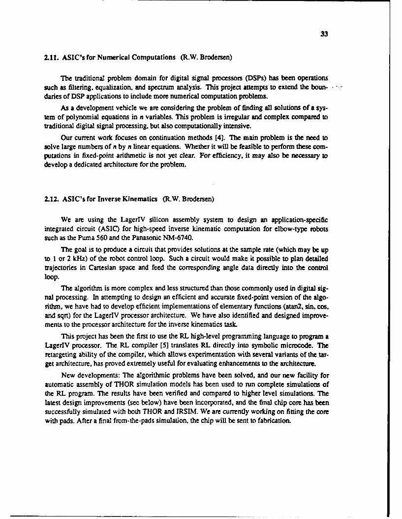
33
2.11. ASIC's for Numerical Computations (R.W. Brodersen)
The traditional problem domain for digital signal processors (DSPs) has been operationssuch as filtering, equalization, and spectrum analysis. This project attempts to extend the boun-daries of DSP applications to include more numerical computation problems.
As a development vehicle we are considering the problem of finding all solutions of a sys-tem of polynomial equations in n variables. This problem is irregular and complex compared totraditional digital signal processing, but also computationally intensive.
Our current work focuses on continuation methods [4]. The main problem is the need tosolve large numbers of n by n linear equations. Whether it will be feasible to perform these com-putations in fixed-point arithmetic is not yet clear. For efficiency, it may also be necessary todevelop a dedicated architecture for the problem.
2.12. ASIC's for Inverse Kinematics (R.W. Brodersen)
We are using the LagerlV silicon assembly system to design an application-specificintegrated circuit (ASIC) for high-speed inverse kinematic computation for elbow-type robotssuch as the Puma 560 and the Panasonic NM-6740.
The goal is to produce a circuit that provides solutions at the sample rate (which may be upto I or 2 kHz) of the robot control loop. Such a circuit would make it possible to plan detailedtrajectories in Cartesian space and feed the corresponding angle data directly into the controlloop.
The algorithm is more complex and less structured than those commonly used in digital sig-nal processing. In attempting to design an efficient and accurate fixed-point version of the algo-rithm, we have had to develop efficient implementations of elementary functions (atan2, sin, cos,and sqrt) for the LagerlV processor architecture. We have also identified and designed improve-ments to the processor architecture for the inverse kinematics task.
This project has been the first to use the RL high-level programming language to program aLagerlV processor. The RL compiler [5] translates RL directly into symbolic microcode. Theretargeting ability of the compiler, which allows experimentation with several variants of the tar-get architecture, has proved extremely useful for evaluating enhancements to the architecture.
New developments: The algorithmic problems have been solved, and our new facility forautomatic assembly of THOR simulation models has been used to run complete simulations ofthe RL program. The results have been verified and compared to higher level simulations. Thelatest design improvements (see below) have been incorporated, and the final chip core has beensuccessfully simulated with both THOR and IRSIM. We are currently working on fitting the corewith pads. After a final from-the-pads simulation, the chip will be sent to fabrication.

34
2.13. A Programmable DSP for LagerIV (R.W. Brodersen)
The Kappa processor architecture was developed by Khalid Azim [6] for the LageriII sili-con assembler. We have ported the design to LagerlV and enhanced the architecturc by includinga newly designed logarithmic shifter and an array multiplier.
It is possible to generate different versions of the processor by selecting parameter valuessuch as wordlengths, memory size, and microcode.
This process is automatic, driven by parameter values. It is also possible to customize suchcharacteristics as the number of registers, multiplier type (array or shift/add), shifter type (vari-able shift from register vs fixed shift from instruction), and interconnections (buses). These
changes require some manual work by the user.
Kappa can be programmed in the RL high-level programming language. [7] special-purposearchitecture of Kappa. We have interfaced the standard version of Kappa to the RL microcodecompiler [ 13] by providing a new Microcode assembler (Mass).
Our effort to automatically assemble THOR simulation models of any given instance of theKappa processor is now sucessfully completed. This has made it possible to simulate the execu-tion of complex RL programs directly on a logic level model of the processor, and at a reasonablespeed (10 processor cycles per cpu second). This is more than an order of magnitude faster thanlayout extraction-based IRSIM simulations.
The access to speedy THOR simulations has prompted a more thorough testing of the archi-tecture, and some fatal bugs in the original processor design have been corrected.
The internal control of Kappa has been redesigned to achieve higher layout density. This •involved changes in the controller architecture, as well as design of new leafcells. The controlunit is now 35% smaller than before and close to optimal for our largest test example.
The latest revision of the design has been brought through entire process from THOR simu-lation to layout, extraction and IRSIM simulation. The functionality of the new design has beenverified.
2.14. Board-Level System Interfacing (R.W. Brodersen)
At the board level, where chips are the building blocks and are interfaced with extra logic,
the development of board design techniques lags behind the development for VLSI chip design.To reduce board design complexity and to ensure functionality and required performance, thisresearch aims to automate the design of interface logic and implementation. The chip com-ponents may use asynchronous or synchronous communication protocols like handshaking totransfer binary data between them. Given the protocols and the system architecture, i.e. commun-ication topology of of who talks to whom, the goal of the interface tool is then to generate circuitsthat properly control protocol event sequencing and ensure that timing requirements are met dur-ing communications. This interface synthesis system provides high-level user input specification,a library database of components, and the actual synthesis tools. 0

35
The input from the user is a block diagram of the system architecture. The block diagram ismade up of blocks which represent components or modules of components, and interconnectionnodes and directed edges which represent interfaces and the logical communication channel thatconnects the module ports, respectively. The interface synthesis program can look up informationnecessary about the component's I/O timing behavior, as its protocol defines, which resides in acomponent library. The block diagram is represented as a netlist in the .sdl format.
The underlying library consists of components and information about their I/0 timingbehavior. I/O timing behavior normally contains many details about the sequencing of I/O eventsand timing relationships between events. These details are tedious for the user to enter for eachdesign, and the library is provided as a convenience to the user and to maintain integrity of thetiming behavior information. The timing behavior is represented as a signal-transition-graph[l]which has event nodes and precedence edges. Timing constraints between events are attached asweights to the graph edges. Currently, this research is exploring representation with theoperation/event-graph model[8], which allows complex control over event sequencing. Thegraphs are stored in the database as a netlist of nodes and edges represented in a textual format,which is currently being developed.
The interface synthesis tool reads from the library the timing behavior of the appropriatecomponents. Then given the communication topology from the block diagram, it can generate theinterface logic. The first step is merging the event-graphs of individual component ports thatcommunicate into one event-graph that represents the I/O timing behavior of the interface. Thealgorithm that merges the graphs will consider different ways of merging the graphs to get dif-ferent performance and cost (of the interface circuit) results. In the next step, the synthesissoftware will include graph check programs which detect consistency errors or enforce a particu-lar graph property to hold prior to actual synthesis. The goal here is to guarantee correctness ofthe logic implementation from the graph specification[l]. Thereupon, a functionally-correctmerged graph specification can be transformed into a state graph from which logic synthesis canbe performed using developed techniques[9].
2.15. Wideband Digital Portable Communications (R.W. Brodersen)
The purpose of this research is to investigate and develop techniques for digital wirelesscommunications capable of handling extremely high data rates, yet in a small, portable device.Clearly, the desire for portability presents the challenge of low power consumption within thesystem, while the desired data rates C10 Mbit/sec) present the conflicting goals of widebandwidths and high data-processing rates. We envision such a device to serve as a terminal of a"micro-cellular" system, similar in spirit to today's cellular phone network, but with a fully digi-tal implementation, capable of handling information transfers well beyond simple voice transmis-sion, including full-motion video. The microcell concept allows for these bandwidth require-ments, allowing high frequency reuse factors and correspondingly high spectrum efficiency, aswell as keeping short transmission distances between mobile and base units.
We are now beginning to examine channel and data encoding, modulation, and detectionschemes which are optimal within these constraints, through extensive use of computer-aided

36
modeling. Furthermore, channel noise, low-antenna multipath propagation, and fading issues in amicrocell transmission environment must be considered. Currently, any such modelling must bedone using field-measured fading/distortion data; we are developing a computer-aided simulationprogram which takes "physical descriptions" of the terrain (eg., placement of buildings, trees, etc)and provides reasonably accurate data concerning the transmission channel.
As a first iteration in developing such a communications system, we are constructing a 10Mbit/sec wireless data link, which would be compatible with current Ethernet standards. Themost promising candidate thus far is a time-division multiple access system, using 16- or 32- qua-drature amplitude modulation with Viterbi error coding.
2.16. Oct2PCB Placement and Routing within LagerIV (R.W. Brodersen)
Until recently, the LagerIV assembly system addressed only the design of custom integratedcircuits. However, most real-time systems, including those we are developing, incorporate com-modity and programmable components, as well as custom devices on the same board. We have,therefore, extended the toolset of the LagerlV system to handle the design of printed circuitboards (PCBs). We have developed interfaces between the Oct database environment and a set ofcommercial PCB tools, such as those offered by Hewlett-Packard and Racal-REDAC, whichallow us to describe the composition of the board using the sd structural language exactly as wewould '-'scribe the composition of a custom integrated circuit. This description, which mightinclude s .:ne constraints on the board topology, is then passed to the commercial tools for place-ment an; routing.
'2urrent efforts focus on enhancing the modularity and features of the PCB description andadding tools for board extraction, modeling (including connectors and backplanes), and electricalsimulation.
2.17. Techniques for Very Fast System Prototyping (J.M. Rabaey, R.W. Brodersen)
Prototyping a system is often the only way to test its correctness and optimize its behaviorwith respect to the initial specifications. System prototyping has traditionally been an extremelytedious operation, using commodity components such as microprocessors and memories com-bined with a lot of glue logic implemented in TIL.
Recent advaices in technology have yielded several components and techniques that couldreduce the prototyping time dramatically. One is the sea-of-gates approach, which allows theintegration of systems of considerable complexity in a moderate turnaround time. Anotherapproach involves the use of Programmable Logic Devices (PLDs), whose complexity hasrecently risen to 9000 gates. This approach offers great flexibility and instantaneous turnaround.
In this project, we have analyzed the use of PLDs for prototyping signal-processing applica-tions such as speech recognition and image processing. The results of those experiments haveallowec us to classify existing PLD devices according to their complexity, flexibility, and

37
architectural features. This information will help us to develop tools for automatic partitioningand architecture selection.
We have implemented an interface between the Lager/Oct environment and commerciallyavailable PLD mapping tools. We have also developed a method for mapping logic equationsinto PLD primitives using MIS-Il and Espresso. To map large designs efficiently into a set ofPLD's, we have developed two partitioning methods. One method uses a fast clustering algo-rithm. Another method uses a linear programming approach to find an optimal solution. Withthis interface, it will be possible to generate PLDs starting from our standard specificationenvironment (sdl VEM) and to compare different implementation techniques (such as custom-cell, gate-array, or PLD) relatively quickly. We are currently targeting PLD's manufactured byActel, Altera, and Xilinx.
We have used this interface to map designs used on a 32 megabyte memory board of ourHMM speech recognition project. These designs include a memory controller, VME interfacelogic, address generation logic, and a saturating adder.
2.18. Fast Prototyping of Video and Speech Systems (J.M. Rabaey)
The implementation and realization of video and speech systems is always cumbersome,requiring extensive time and resources. The high performance constraints force the designer touise either a bulky TL board or custom-designed chips, both of which are expensive.
This project attempts to speed up prototyping by defining a library of macrocomponents at ahigh enough level to simplify the board design but still flexible enough for a wide variety ofhigh-performance signal-processing applications. To define the contents of the library and thedesired programmability and functionality, we are currently examining a set of image- andvideo-processing algorithms as well as some problems in speech recognition. These includerecursive filters, matrix conversion from RGB to luminance and chrominance for video, linearand non-linear image filtering using linear convolution and sorting algorithms respectively,dynamic time warping and Hidden Markov based algorithms for speech recognition, and others.
We have observed that most of these systems are implemented as a set of concurrentlyoperating, bitsliced and pipelined-processors. The connection and communication patterns, thecontroller structure, the datapath composition, and the memory organization of the processors,however, depends heavily upon the application. For each entity, we are trying to define a res-tricted set of programmable components that covers most of the architectural alternatives. Fourclasses of devices are necessary: datapath blocks, controllers, memory (including delay lines),and interprocessor communication units.
Fairly efficient solutions are available for control structures (using programmable logic dev-ices) and memory structures. However, no high-level re-programmable datapath or interproces-sor communication structures are yet available. We are trying to find ways to realize high-leveldatapath and communication components using both laser and software-programmable on-chipinterconnect and multiple buffering register files.
Several key issues have been identified for the datapath blocks: granularity of the process-ing elements (PE's), choice of the operator(s) for the PEs, interconnectivity between PEs,

38
communication of control flags between PEs and the controller, datapath widths, and I/Obandwidth. The prototype, dubbed PADDI for Programmable Arithmetic Devices for DigitalSignal Processing, has been designed to cover a range (1-10) of sampling-interval-to-clock ratiosto handle lowly multiplexed to highly multiplexed datapaths. PADDI contains 8-bit linkable exe-cution units, a statically programmable hierarchical interconnect network, and a hierarchical con-trol mechani.'m. The initial design envisions a central external controller chip that implementsthe control flow of the algorithms and broadcasts the state to different execution units, which mayreside on different chips. Fast programmable state sequencers are commercially available for thispurpose. A local nanostore determines the operations to be performed on a particular datapath.Both the nanostore and the configuration memory for the interconnection network can be loadedserially upon initialization. We anticipate that the nanostore will also be able to provide a nextstate address for branching. We are currently in the process of defining the micro-architecture andVLSI floor-planning for PADDI.
Because a hardware synthesis and verification environment will be crucial to the success offast prototyping, this project also involves developing software tools to map a system definitioninto the hardware macrocomponent library and automatically generating functional and electricalsimulation models.
2.19. HYPER - An Interactive Synthesis Environment for High-Performance Real-TimeApplications (J.M. Rabaey)
The goal of this project is to build an interactive environment for the design of high-performance real-time processors, consisting of the following major elements:
(1) The algorithm to be implemented must be specified either graphically or textually. Wehave extended Silage [1] to describe control constructs for register-level descriptions anddeveloped a graphic front-end based on VEM/RPC.
(2) From the input specification, a mixed signal-flow/control-flow graph is derived. Theundecorated flow graph, generated by the parser, is then passed to a scheduling and optimi-zation pass. These techniques are described in [10].
(3) From the resulting scheduled graph, we can synthtsize the datapaths, the controller, and theinterface logic. All these steps require accurate information about the available cell library(speed, area, black-box view, and functionality); this information is provided by a rule-based library database. The final layouts of the processors are generated with the Lager IVsystem. A program that translates a decorated flow-graph description to the SDL (structuredescription language) has been developed.
The hardware mapping process consists of three routines that translate the datapaths, thecontroller, and the interface logic. The hardware mapping of datapaths requires a suite oftransformation steps, including multiplexer reduction, hardware choices of assign operations, anddata path partitioning. The details of these operations can be found in [3]. Several translationsteps are also introduced to the system to handle signal broadcasting and arithmetic commuta-tivity.
39
Datapath partitioning is based on three criteria. First, a depth first search is performedthrough the hardware graph. Each group is further divided if different word lengths are foundwithin the group. If the number of blocks in a group is still too large, a simulated annealing-based algorithm is used for solving the min-cut problem.
The control path of a processor can also be derived from the decorated flow-graph. FMrst, astate-transition diagram is generated from the scheduling information; then the transition diagramis optimized by removing the dummy states. The controller structure is generated in this step.Several optimizations are performed to reduce the size of the controller and to simplify the wiringbetween the control path and the datapath: these include recognizing the control signals that areindependent of control states, merging equivalent or complementary signals, and allocating theminimum number of control registers by lifetime analysis.
Several extensions of the system have been made since last proposal. First, Control slicesbetween datapaths and central control are partitioned according to the partitioning of the data-paths. This greatly improved the layout quality. Logic optimization is also performed on thecontrol slices to reduce redundant logic. Another extension is that bus structure of control signalsare allowed to handle cases such as log shifters and register files.
We have been able to generate the layouts of a 7th order lIR filter from Silage descriptionand use THOR to simulate the functionality of the structure description generated by HYPER.Several examples, including the epsilon processor and the Viterbi processor of our Hidden Mar-kov Model (HMM) speech projects, have also been generated from the flow-graph description.We can easily study the tradeoffs of different scheduling and hardware allocation schemes byusing HYPER. Future research will involve the estimation and hardware allocation scheme ofHYPER, introducing more translation and transformation routines, and rewriting the databasesystem in OCT to improve performance.
2.20. High-Quality Speech Coding for Portable Communications (.M. Rabaey)
This research focuses on the evaluation of high-quality speech coding algorithms and willresult in an implementation for use in a portable communications system. The evaluation phaseconsists of analysis and simulation of several candidate algorithms. High-quality and relativelylow bit-rate (-16 Kb/s) operation suggest a robust CELP (Code-Excited Linear Prediction) algo-rithm. In CELP coding, a search algorithm periodically selects an optimum excitation sequencefrom a vector quantized code-book. An index to this vector is then transmitted and used to excitea synthesis filter in the decoder. The decoder filter parameters are then updated in a backwardadaptive fashion.
Since this coder must function in a portable environment, low power dissipation is an over-riding concern. Suitability for a low-power, real-time implementation will undoubtedly influencealgorithm selection and customization. Indeed, much of this study will focus on analyzing anddeveloping VLSI architectures and design styles suitable for low-power operation. This analysisbased on fundamentals of complexity theory, statistical analysis, and simulation should lead todesign styles and methodologies suitable for low-power implementations. The research isrelevant not only for this particular application, but also for a wide range of DSP algorithms
40
constrained to low-power operation.
2.21. Partitioning DSP Algorithms onto Multiprocessors with Configurable Interconnec-tion (.M. Rabaey)
Multiple programmable digital processors are used to handle the computationally intensive 9behavioral simulation of DSP algorithms. To minimize the communication overhead, the proces-sors are connected by a bus that can be configured by software to match the communication pat-tern of each particular algorithm. To minimize the idling time, an efficient heuristic to balanceprocessor loads is being investigated. This algorithm uses estimates of the computation tine andcommunication time of the individual atomic tasks to optimally partition the program onto theprocessors. First, pipelining and retiming at the block level will be performed. Then, within thesub-block, parallelism or further pipelining can be used to exploit the finer grain concurrency.
The ultimate goal of this project is to provide an environment where users can express DSPalgorithms textually or graphically, and have a compiler partition and translate the program intosections of assembly code to be executed on the multiprocessor system. The compiler willconfigure the bus to minimize the communication overhead.
A prototype of the multiprocessor system (SMART) has been built. It consists of 10DSP32C Digital Signal Processors as well as custom VLSI chips to handle the communicationand synchronization between processors.
The Silage To SMART (S2S) Compiler, which implements the partitioning algorithm, isunder development. It is composed of 4 tasks:
1 Silage to Flowgraph (S2F) Translation
2 Flowgraph Partitioning
3 Flowgraph to C (FF2C) Translation •
4 C to DSP32C Code Compilation
The Silage to flowgraph translation is complete. The flowgraph partitioning performs pipe-lining, retiming, and parallelism simultaneously under one global search strategy. Tbe algorithmalso automatically break the nodes of the graph to the appropriate level of granularity while parti-tioning. Initial results from the flowgraph partitioning are very good. Further research areneeded in modeling communication costs between processors accurately, as well as in handlingmultirate DSP applications.
The first version of the flowgraph to C translation has been implemented, which can executeon Sun Workstations. The ultimate goal is to use AT&T's C compiler for the DSP32C to gen-erate code for the processors. To yield efficient code, an in-depth study of the characteristics ofthe C compiler will be done.
2.22. SMART: Switchable Multiprocessor Arhitecture with Real-Time Support (.M.Rabaey) 0

41
A major part of the design effort for DSP systems is devoted to algorithmic specificationand verification. Executing these simulations on a general-purpose computer requires so muchCPU-time that real-time simulations of certain algorithms are impossible. The main purpose ofthis project is to develop a dedicated simulation engine at least two orders of magnitude fasterthan a general-purpose computer architecture of the same techmology level. To handle thenumber-crunching bottleneck, we are using a floating-point DSP processor (the DSP32C fromAT&T Bell Laboratories) as the core processor. On this processor, simulations run at least anorder of magnitude faster than on a general-purpose microprocessor.
An additional order-of-magnitude gain in simulation speed can be obtained by exploitingthe high degree of parallelism and pipelining inherent in most signal-processing algorithms. Wehave proposed a multiprocessor architecture with a software-reonfigurable communication pat-tern that permits the processor architecture to be adjusted to match the concurrency and pipelin-ing properties of the algorithm.
Two 208-pin VLSI chips have been designed and tested to handle communication and syn-chronization between the processors and to manage memory access. A prototype of the system isimplemented and operational at peak 120 MFLOPS with 10 processing units. Applicationsoftware programs such as diagnostic testing, image processing, and 1024-points FFT weredeveloped to measure the performance of the architecture. Future efforts are directed to thedevelopments of more application programs, the custom high-speed I/O interface, and the perfor-mance enhancement of th' prototype system (200 MFLOPS) for same number of processors.
2.23. Extended THOR (J.M. Rabaey)
THOR is a functional simulator based on the CSIM simulator, a conventional event-drivenfunctional/behavioral simulator. To describe a system in the THOR environment, the user has toprovide the models of the system modules and their interconnections. The modules are written ina language called CHDL (C Hardware Description Language). CHDL is based on the C pro-gramming language with added features for hardware modeling. The interconnection networkdescription is provided in a component-oriented nct list language, called CSL.
THOR implements some of the features, which are essential in a heterogeneous simulationenvironment.
Since the leaf modules in THOR are described in standard C, it is possible to link in avariety of "foreign" or external simulators, such as a SILAGE or a Motorola 68000 simula-tor.
The THOR simulation engine handles the intermodule communications. Unfortunately, thepresent THOR is based solely on the event driven protocol, which is sufficient for structuralsimulation. As described above however, a system level simulation environment equallyrequires the data flow and communication processes based mechanisms.
The LAGER silicon assembly system makes extensive use of the THOR environment formodeling and simulation at the structural level. And the extension of the THOR environment,which will have most of the properties required for heterogeneous simulation, becomes essential.

42
The CSL language will be replaced by the sdl/OCT-SIV descriptions of the LAGERenvironment. This will improve the parameterizability and the descriptive power.
The introduction of foreign simulators will be simplified by providing a library of interfaceroutines. This will make the interconnection mechanisms transparent to the user.
The simulation engine will be adapted to incorporate a variety of communication mechan-isms.
The extended THOR will handle multi-processor simulation and hard simulation. This will once again be achieved by providing a set of library-routines, which hide the physicalimplementation of those interfaces to the user.
2.24. Behavioral Transformations for the Synthesis of High-Performance DSP Systems(J.M. Rabaey)
To solve a given computational problem, one can use a large number of algorithms. Oftenany one of these algorithms can lead to several implementations, each with vastly different timeof execution, hardware requirements, power constraints, and testability. Since the flow graphspecified by the designer often fails to meet the performance specifications or results in an infe-rior realization, optimizing transformations must be applied. Most of the behavioral transforma-tions are well known from optimizing software compilers; they include constant arithmetic, com-mon subexpression elimination, and dead-code elimination. More important are the looptransformations: loop retiming, loop pipelining, partial or complete loop unrolling, and loop jam-ming. These latter transformations are especially suitable real-time systems, in which each pro-gram contains an infinite loop of time and concurrency can be exploited more efficiently by con-trolling the hardware resources.
We are implementing a search-driven transformation environment where the order and typeof the transformations are determined by the table of hardware-utilization ratios. The sameenvironment can also support other high-level synthesis tasks such as module and clock selection,partitioning, pipelining, design-style selection, assignment, and scheduling.
We started implementation of transformations by implementation of basic block transfor-mation. Those include commutativity, associativity, distributivity, retiming, constant evaluation,pipelining and software pipelining. We developed new algorithm based on Welsh randomizedalgorithm which apply just mention transformations in such way that we can schedule resultingsignal flow graph in a minimum amount of time on a given hardware configuration. The firstresult (we completed implementation of commutativity) are very promising.
2.25. Scheduling and Resource Allocation In the Design of High-Performance Digital Sig-nal Processor" (J.M. Rabaey)
The goal of this project is to minimize the total hardware cost of an implementation of a tar-get program represented by a signal-flow graph (or data-dependency graph), given constraints onexecution time, timing, and hardware. The hardware cost function is composed of the cost of the
43
functional units, memory, and connectivity.
An overview of the state of the art in this area is given in [I]. None of the availableapproaches, however, allows a consistent and unbiased treatment of the three contributions to thecost function: execution units, memory, and interconnect. Furthermore, most available tech-niques remove all hierarchies from the flow graph before scheduling: functions are expanded, andloops are unrolled, resulting in huge graphs for most problems. We have been developing a suiteof algorithms that address these deficiencies.
The new technique has four parts: control strategy, estimation, assignment, and generationof the exact solution (scheduling).
We finished implementation of the new assignment and scheduling algorithm. From thealgorithmic point of view there are three new features: (i) it is combination of probabilistic andclassical constructive algorithms; (ii) the probabilistic algorithm is rejectionless; and (iii) theclassical constructive algorithm is based on the idea of discrete relaxation. The simple extensionis making incorporation of specific transformation (commutativity) simple and efficient.
We show excellent results on a number of examples. Running time for examples with up toa hundred nodes is less than I second. We introduce a broad class of test examples and the idea ofestimation which makes assessment of scheduling and assignment algorithms easier and morerealistic. Also, we demonstrated on those examples the simple and efficient approach of tradingthe speed of scheduling for the quality.
2.26. A Hardware Environment for Rapid Prototyping of DSP Systems (I.M. Rabaey)
The main goal of this project is to provide a rapid prototyping hardware environment fordesigners of DSP systems. The key part of the system that we envision is a dynamicallyconfigurable network with high communication bandwidth. In addition to data routing, the net-work also supports features such as broadcasting and merging data.
During the early phase of the design cycle, designers can simulate their algorithms by plug-ging processor boards into our system. The network integrates these processors together to form amulti-processor simulation engine which provides high computation throughput as required bymany DSP algorithms. The network can be configured according to the communication patternsof the algorithms to reduce overheads due to inter-processor communication. Heterogeneous pro-cessors, e.g., DSP's and RISC's, can be used to suit the nature of the computation. As the systemevolves, ASIC's replace certain sub-systems where high performance is desired while the rest ofthe system, such as some front-end processing, can still be emulated by the processors.
Our system shortens design time by providing high computation throughput and program-mability throughout the development cycle so that designers can get fast feedback of performanceand hardware problems. It also eases the integration of custom-designed hardware into the finalsystem.
Problems that we have to address include system extensibility, I/O requirements of the sys-tem, standardization of the bus protocol and the design of the communication network.

44
2.27. Pulsar Signal Recovery (J.M. Rabaey)
Pulsars are rotating, highly magnetized neutron stars which emit sharp pulses with high sta-bility of frequency. Pulsar timing has a number of applications. However, to achieve pulsar tim-ing, the signals which have been dispersed by propogation through the interstellar medium, haveto be passed through a de-dispersion filter on the receiver end. The coherent de-dispersion tech-nique involves implementing the inverse interstellar medium transfer function in an FIR filter.However, to de-disperse the entire 100 Mhz bandwidth of the signal would require a FIR filter of •an order of a million taps.
Since such a huge FIR filter is not feasable, the current research is in making an FIR filterwhich would implement a 1000 tap FIR filter which would de-disperse about 1 Mhz of the signalbandwidth. Currently, we are carrying simulations on word length effects on the signal recovery.Once the word lengths are decided upon, the de-dispersion filter would be converted to a VLSI 0chip.
2.28. Frigg: A Simulation Environment for Multiple-Processor DSP Hardware Develop-ment (E.A. Lee)
In the last six months we completed and terminated this project, the construction of designaids for systems using commodity programmable DSPs. We view this as a promising start onbetter integrated design environments that incorporate heterogeneous models of computation. Inthis case, we have interfaced the hardware design environment to Gabriel, which synthesizesassembly code for programmable DSPs. So the designer's view of the system simultaneouslyincorporates a dataflow representautc of the signal processing application and a netlist represen-tation of the hardware being designe4 ",o implement that application.
Many practical DSP problems require systems with multiple programmable DSPs.Developing multi-processor systems is complicated, and traditional development tools do notprovide adequate support. While simulators exist for all programmable DSPs, there has been noready way for developers to simulate the interaction between a programmable DSP and otherdigital hardware, or between multiple (possibly heterogeneous) DSPs. This lack of flexible simu-lation capabilities has often meant long delays in hardware development, and the postponement 0of software testing and debugging until after hardware prototypes are built.
We have designed and implemented a simulation environment that meets the needs ofdeveloper of multi-DSP systems. Our simulator, Frigg, uses the Thor simulator from StanfordUniversity as the simulation substrate. Thor is used to simulate all hardware elements other thanDSPs, and to simulate all interconnections between elements. Frigg integrates the capabilities of •Thor with those of manufacturer-supplied DSP simulators. The X window system is used to pro-vide a multi-window user interface which allows a user to easily select and interact with differentprocessing elements. Frigg uses the interprocess communications (IPC) facilities of Unix to inter-face independent cooperating simulation processes, which can run on different hosts. The com-munication mechanism developed is general, and may be used in the future to interconnect a •wide variety of simulators in a multi-mode simulation environment.
I I l
45
Frigg has been interfaced to Gabriel, a graphical data-flow programming system (with arbi-trary granularity) for multiple programmable DSP systems. A designer can create a new architec-ture by specifying the Thor models and creating the netlist. Then those properties of the architec-ture that are relevant to code generation, such as the number of processors and the interprocessor .,
communication mechanism, are summarized in a form readable to Gabriel. Gabriel can then takeany application program and produce code for the new architecture. An attempt has been made tomake the Gabriel core as independent as possible of details of the target architecture, but morework is warranted to get truly easy retargetability.
Finally, we have assembled a laboratory facility for experimentation with multiprocessorDSP hardware and software. Currently, a four-processor DSP56000-based system is running inthe lab, and has been integrated with other lab resources. The prototype system was donated byDolby Laboratories, a San Francisco company. The system has been interfaced to Gabriel, usingthe hardware description mechanism described above. We have demonstrated that Gabriel canautomatically synthesize code for the system without requiring that the user have anyarchitecture-specific knowledge.
2.29. Heterogeneous Hardware Targets (E.A. Lee)
The Gabriel software system is capable of running local simulations of a signal processingsystem on a workstation, or generating assembly code for real-time execution. Unfortunately, atthis time, the designer must choose between these two modes of operation, rather than a morenatural mode that would allow a mixed system that involves interaction between the workstationand the real-time DSP hardware. The next generation software environment (called Ptolemy,described separately) will support such mixed systems naturally by supporting cooperationbetween distinct scheduling models. The aim of this project is to determine how to use this newcapability to automatically target heterogeneous hardware architectures. The first such target willbe a workstation with a programmable DSP-based board on its bus. An application program willsimultaneously specify the activity in the workstation and on the DSP board, and the interactionbetween the two, but to the system designcr the interface will appear seamless. To begin thiseffort we have developed an interface between a VME-based development system for theMotorola DSP56001 and Sun 3 system. The interface has been developed using Gabriel pendingsufficient capability in its replacement system. The limitations of the VME bus and Sun 3 works-tation restrict the real-time transfer rate of our interface to somewhat less than 20,000 samples persecond. To proceed to the next logical step, therefore, we have cooperated with a small localcompany that is producing a DSP56001 board that will reside on the S-bus of a Sun Sparc works-tation. We are developing the appropriate device driver and will begin to design closely interact-ing applications that use both computation resources, the DSP and the workstation.
2.30. Ptolemy: A Non-Dogmatic Third Generation Simulation Environment (E.A. Lee andD.G. Messerschmitt)

46
We have implemented and had considerable user experience with two generations of DSPsimulation environments, Blosim and Gabriel. Both environments used a block-diagram data-flow paradigm for the description of the algorithms. For the future we see the need for othercomputational models, such as discrete-event scheduling, mixed compile-time and run-timescheduling, or computational models based on shared-memory data structures. These am not sup-ported very gracefully by Blosim or Gabriel. Most importantly, we see the need for a flexiblesimulation environment which is extensible to new computational models without re-implementation of the system. •
This has led us to begin development of a new environment which uses object-oriented pro-gramming methodology. Our goal is to make it non-dogmatic, in the sense that the environmentitself does not impose any particular computational model, and it is extensible to new models bysimply adding to the system and not modifying what is already there. Further goals are to incor-porate features that have been successful in Blosim or Gabriel, such as achieving modularity and 0reusability of user-programmed software modules, friendly graphical window interfaces, andcode generation for target concurrent architectures rather than just simulation.
A first version of the system currently has a synchronous data-flow scheduler and anembryonic discrete-event scheduler. This system will thus immediately be capable of simulatingcombinations of signal processing and network simulations (such as in packet speech and packetvideo) and combinations of behavioral and hardware simulation. We are currently working oninterfacing the system to the same graphical interface used by Gabriel, which uses Vein to editOct facets. Consequently, Oct serves as the design database for the system, just as with Gabriel.
REFERENCES
[1] P. A. Ruetz and R. W. Brodersen, "Architectures and Design Techniques for Real-TimeImage-Processing IC's," IEEE Journal Solid-State Circuits, April 1987, p.233 0
[2] B. Richards, "Design of a Video Histogrammer Using Automated Layout Tools," UCBerkeley Electronics Research Laboratory, Memorandum No. UCB/ERL M86/38, 1986.
[3] See M. Srivastava, "Dedicated Real-Time Systems for Robotics," in this chapter of theResearch Summary.
[4] T.A. Chu,"Synthesis of Self-Timed Control Circuits from Graph-Theoretic Specifications,"1987 IEEE International Conference on Computer Design
[5] T. Amon, G. Borriello, C. Sequin, "Operation/Event Graphs and OESIM," Technical Report#90-01-17, Dept. of Computer Science and Engineering FR-35, Univ. of WA, Jan. 1990.
[6] T.H.Y. Meng, R.W. Brodersen, D.G. Messerschmitt, "Automatic Synthesis of Asynchro- 0nous Circuits from High-Level Specifications," IEEE Transactions on Computer-Aided

47
Design, Vol. 8, No. 11, Nov. 1989.
[7] P. Hilfinger, "QA High Level Language and Silicon Compiler for Digital Signal Process-
ing", Proc. Custom lnregrataed Circuits, Conf., Portland, OR, May 1985, pp. 213-216. -
[8] M. Potkonjak and J. Rabaey, "Q:A Scheduling and Resource Allocation Algorithm for
Hierarchical Signal Flow Graphs" Proc. Design Automation Conference, Las Vegas, NV.June 1989.
[91 C. Cbu, et a., HYPER: An Interactive Synthesis Environment for "HYPER: An InteractiveSynthesis Environment for High Performance Real Time Applications," Proc. ICCD, Bos-ton, October, 19889.
[10 W. Koh, A. Yeungk, P. Hoang, and J. Rabaey, "A Configurable Multiprocessor System forDSP Behavioral Simulation," ISCAS Symposium, May, 1989.