Embed Size (px)
Citation preview

•7
AD-A012 110
AN INVESTIGATION OF TECHNIQUES FOR ACHIEVING EXPOSED AGGREGATE SURFACES FOR SITE-CAST CONCRETE
Daniel J. Naus, et al
Army Construction Engineering Research Laboratory Champaign, Illinois
June 1975
DISTRIBUTED BY:
KfDi National Technical Information Service U. S. DEPARTMENT OF COMMERCE

wn^&*^?'^tw*mmHmmmmwmW!*',■ - '' .: ■■ .•■■■■■ ' tW ■&*/!':■*■<?■•■•*■
202061-
construction engineering research laboratory
TECHNICAL REPORT M-61 (RevlMd) June 1975
w
AN INVESTIGATION OF TECHNIQUES FOR ACHIEVING EXPOSED AGGREGATE
SURFACES FOR SITE-CAST CONCRETE
Reproduced by
NATIONAL TECHNICAL INFORMATION SERVICE
US Department of Commerce Springfield. VA. 2215)
by DanMJ.Nuf
Randy Freeman Wayne Mob
G. R. WUIlamBon
y D c p: ■i ,■—,
MI Hi ,
i • m i. / '■■■
üÜ3£J 'r "n VhU Ui
—^ B ^r
III ■■■
Approved for public release; distribution unlimited.
M

The oontonts of ibis report are not to he used for advertising, publication, or promotional purposes. Citation of trade names does not constitute an official indorsement or approval of the use of such commercial products. The findings of this report are not to he construed as an official Department of the Army position, unless so designated hy other authorized documents.
, ;.j,ii,'U.;r toots
DESTROY THIS REPORT WHEN IT IS .WO LONGER NEEDED
DO NOT RETURN IT TO THE ORIGIN A TOR

jK-iim -.,■> wm ■ < -vw
UNCLASSIFIED SECURITY CLASSIFICATION OP THIS »AOC (Whmt DM* Bnl*r*«
REPORT DOCUMENTATION PAGE READ INSTRUCTIONS BEFORE COMPLETING FORM
I. REPORT NÜBiil
CERL-TR-M-M (Revised)
2. GOVT ACCESSION NO 1 RECIPIENT'S CATALOG NUMBER
4 TITLE fand SublltU)
AN INVESTIGATION OF TECHNIQUES FOR ACHIEVING EXPOSED AGGREGATE SURFACES FOR SITE-CAST CONCRETE
S TYPE OP REPORT A PERIOD COVERED
FINAL REPORT
S. PERFORMING ORO. REPORT NUMBER
i. CONTRACT OR GRANT NUMBER^*) 7 AUTHORS Daniel J. Naus Randy Freeman Wayne Muir
G. R. Williamson
9. PERFORMING ORGANIZATION NAME AND ADDRESS CONSTRUCTION ENGINEERING RESEARCH LABORATORY P.O. Box 4005 Champaign, Illinois 61820
10 PROGRAM ELEMENT. PROJECT. TASK AREA A «ORK UNIT NUMBERS
4DM78012A0K1-03-004
11. CONTROLLING OFFICE NAME AND ADDRESS 12. REPORT DATE June 1975
13. NUMBER OF PAGES . NUMBERO
I« MONITORING AGENCY NAME A AODRESV" <UII»tml Itnm Contro/ltnf OWc») IS. SECURITY CLASS, (ol M» tmpott)
Unclassified ISa. DECLASSIFICATION/DOWNGRADING
SCHEDULE
IS. DISTRIBUTION STATEMENT (ol tfi/a Raporf)
Approved for public release; distribution unlimited.
17. DISTRIBUTION STATEMENT (ol Uta mbKtmel anfarad In Block 70, II dlllnmtl from Rmporl)
IB. SUPPLEMENTARY NOTES
19 KEY WORDS (Conllnum on rayaraa mid» II nacaaaary and Idmnilly by block numbtr)
site cist concrete exposed aggregate finish chemical retardation mechanical finishing
20 ABSTRACT CCondnua on rararaa «Ida If nacaaaary aid Idmnilly by block nambor)
This report describes techniques for producing acceptable exposed aggregate finishes tor site cast concrete, including chemical retardation and mechanical methods. Potentially promising techniques are evaluated with regard to labor requirements, material requirements, cost factors, and limitations.
00,^7,1473 EDITION OP t MOV •» It OBSOLETE UNCLASSIFIED
SECURITY CLASSIFICATrON OF THIf ^AOE (Whun Dim Bntmrmd)

■ ■ ■
FOREWORD
This investigation was conducted by the U.S. Army Construction Engineering Re- search Laboratory (CERL). The work was performed under Project 4DM78Ü12AOK1, "Engineering ( ritcria for Design Construction," Task 03, "Application of Construc- tion Methods." Work Unit 004. "Methods of Achieving Exposed Aggregate Facing for Site-Cast Concrete." The Technical Monitor was Mr. R. Licbhardt.
This report was originally published December 1973, but has been extensively revised.
Special recognition is given to Mr. James Shilstone of Architectural Concrete Con- sultants for his help in obtaining information and data on architectural concrete, and tor his review and constructive criticism of the report.
CERL personnel directly concerned with this siu»iy were Wayne Muir, Randy Freeman, and Dr. D. J. Naus of Construction Materials Branch (Dr. G. Williamson, Chief). Materials Systems and Science Division (J. J. Healy. Chief). COL M. D. Remus is Commander and Director of CERL and Dr. L. R. Shaffer is Deputy Director.
Preceding page blank

CONTENTS
DD FORM 1473 1 FOREWORD 3
1 INTRODUCTION 5 Probltm Stat«mtnt Objtctiv« Approach and Scopa Dlacussion Datlnllion
2 EXPOSED AGGREQATE FINISHES FOR SITE-CAST CONCRETE . .5 Introduction Mix Daaign Forma Chamical Ratardation Mechanical Flniahing Rapalrof Expoaad Aggragata Concrata Surfacaa
3 CONCLUSIONS AND RECOMMENDATIONS 11 Concluaiona Racommandationa
APPENDIX A: Altamat« Tachnlquas for Producing Expoaad Aggragata Finishes 14
APPENDIX B: Form Liners 16

AN INVESTIGATION OF TECHNIQUES FOR ACHIEVING EXPOSED AGGREGATE SURFACES FOR SITE-CAST CONCRETE coarse aggregate to varying degrees and texture»,
1 INTRODUCTION EXPOSED AGGREGATE FINISHES FOR SITE-CA: T CONCRETE
Probltm Stlltmtnt. During the next 4 years the Corps of Engineers will be responsible for building Volunteer Army facilities and other structures et a construction value of over SI billion. Although re- defined objectives resulting from the Volunteer Army program have placed greater emphasis on the aesthetic aspects of site-cast structures, much Corps construction will involvt the use of reinforced con- crete—which can have an unpleasing appearance when subjected to substandard placement proce- dures. One potential solution for obtaining concrete structures free of placement defects is the use of cast- in-place exposed aggregate.
Objective. The objective of this investigation is to present an overview of architectural concrete, and to identify techniques for producing acceptable ex- posed aggregate finishes for site-cast concrete so that the economic advantages of reinforced concrete may h: more fully realized.
Approach and Scope. A general overview of archi- tectural concrete was conducted to identify tech- niques which can he used to produce visually attrac- tive site-cast concrete. Potentially promising tech- niques were evaluated for labor requirements, material requirements, cost factors, and limitations. Precast element facings and form liners which pro- duce textured concrete surfaces were investigated as alternative techniques for obtaining architectural concrete facings (see Appendices A and B).
Discussion. This investigation revealed that many design and construction experts consider architec- tural concrete little more than a slight variation of structural concrete. This is not the case. Mix design and placement procedures differ greatly, and if acceptable results are to be achieved, only those with a wide knowledge of architectural concrete should be involved in the design and construction of the material.
Definition. In this report, exposed aggregate site- cast concrete is defined as concrete from which a uniform, visually acceptable result is produced by re- moving the surface skin to expose the substrate con- sisting of cementitious paste, fine aggregate and/or
Introduction. Techniques for producing site-cast exposed aggregate concrete finishes involve either chemical retardation or mechanical finishing. Each is discussed later in this chapter.
Mix Design. The design of the concrete mix must he related to the finish objective. Design practices routinely acceptable for structural concrete mixes give little consideration to architectural results. When the objeciive is an exposed aggregate finish, the mix design must provide both structural integrity and enough uniformly distributed particles in the mix to produce the desired appearance. Regardless of finish objective, the water/cement ratio should be low to minimize potential problems of segregation and/or excessive shrinkage cracks. In designing the mix, it should be recognized that the concrete will be used primarily in vertical construction to be consoli- dated hy mechanical vibrators. Many standard structural concrete mixes are designed for finishing Hat slabs as well as tor vertical construction. The mortar required for slab finishing, however, is not necessarily required for vertical construction. The demands of lay-down type buckets and pumps should not he given preference over the architectural finish in the mix design. The equipment should be compatible to the mix and not vice versa.
In light textures, the paste and fine aggregate dis- tribution are important: in these cases, conventional structural concrete mix design processes are frequently adequate. When heavy coarse aggregate texture is a major architectural feature, however, special mix design techniques are essential. Use of coarse aggregate dry-rodded unit weight and sand fineness modulus is a good basis for architectural mix designs. Tables currently available from indus- try are seldom adequate as they are not founded upon modern placing techniques or architectural re- sults. Competent specialists should therefore be sought out to assure production of the intended re- sults. High coarse aggregate factor mixes will require use of a low fineness modulus sand. Limitations of ASTM C-33 do not necessarily have to be observed. For finishes of heavy abrasive blasted or retarded exposed aggregate, the principles of gap grading should be used.

■OTF
Forms. Erection of watertight forms is necessary for all architectural concrete because any loss of mois- ture or grout from the concrete will produce either surface discolorations or honeycombing. All joints must be sealed to prevent leakage and all corners should be sealed by closed cell compressible neoprene gaskets. When a heavy texture is to be used, face butt joints should be covered with tape. When a light texture is required, face butt joints should be covered with a grooved rustication und the form sealed before application of the retarder. Con- struction joints should be articulated by a grooved rustication with the first casting of concrete carried to the top of the root of the rustication. The joint can be made tight by applying a closed cell compressible neoprene gasket over the root of the subsequent form ami pulling this tight against the previous casting.
Chemical Retardation. Exposed aggregate con- crete surfaces produced by chemical retardation are used primarily in the precast concrete industry, where the exposed aggregate surface is cast horizon- tally and a high degree of quality control can be maintained.* A uniform surface is very difficult to obtain for vertically cast-in-place surfaces using chemical retardation. Part of the difficulty is that all of the chemical retarders studied were partially solu- ble in water. This causes varying degrees of etch for a vertically cast surface because as each lift is vibrated the soluble part of the retarder migrates vertically along the form face, producing an increased concen- tration of retardant with each succeeding concrete lift. Also, if improper concrete placement techniques are used and the concrete is dropped so that it con- tacts the forms above the placement level, the chemi- cal action of the retarder could be initiated above that level. As a result, when the placement level reaches the level where the concrete previously came in contact with the form, the chemical action would cease and an area where chemical retardation does not occur would result, producing a hard spot. The chemical process can be used effectively in limited areas under very close control. The types of retarders best suited for the specified mix must be carefully evaluated. Some products are suitable for one mix but not another.
PmcfJure. The best procedure to follow in using a
chemical retarder consists of six steps; form erec- tion, application of retardant, concrete mix design, concrete placement, form removal, and surface removal.
The chemical retarder must be applied on a high- quality form to achieve the best results. The product should be carefully applied in accordance with the manufacturer's recommendations and allowed to dry. Excessive or uneven application will result in nonuniform etching that can produce unsightly sur- face blemishes.
An alternative to the liquid retarder is retarder paper, a chemically treated paper that is attached as a form liner. The impregnated paper offers the advantage of assuring factory-controlled uniform distribution of the chemical. Like the liquid products, it is partially soluble in water and subject to abrasion during concrete placement—thus can have some of the same disadvantages.
Concrete must be placed and compacted with care. During placement it is important that the con- crcte does not contact the form faces above the cur- rent placement level, to avoid premature retardant action. A "tremie" should be used for placement to avoid splashing of the concrete against the form face.
The forms should be stripped according to the schedule recommended by the retardant manufac- turer. Immediately after stripping, the concrete surface must be washed and brushed to expose the aggregate. Forms should not be stripped until workers are available to brush the surface.
Figure I shows exposed aggregate surfaces pro- duced by using chemical retardants.
Cost Factors. Cost factors'*2 vary with the source of information; however, a range of costs can be established. Material costs for the chemical retard- ant, whether liquid or paper, range from $0.30 to $0.80/sq ft. Labor costs for application of the re- tardant and brushing range from $0.20 to SO^S/sq
•Poor-quality surfaces (e.g., blemished, honeycombed areas) may be rejected for precast elements but not so readily for site- cast .
1 Anhilerti Conlraclors Enginren Guide to Construction Costs (Concrete Construction Publications, Inc., June 1972).
' R. M. Gensert. "Cost Factors for Cast-ln-Placc Architectural Cmcntc," Journal of American Concrete Institute. Vol 69, No. I (January 1972), pp 36-45.

PAPER RETARDANT
LIQUID RETARDANT
Figure 1. Exposed aggregate surfaces produced by using chcmical retardants.
7

ft. CJenerally. rciardcrs are used «hen heavy texture is required. Sueh texture increases costs because it requires a very high coarse aggregate factor and creates an added placement cost. These factors should he considered in establishing the budget for the project.
I imiitiiioHs. A uniform, relatively hlemish-lree vertical surface for site-cast exposed aggregate sur- faces is difficult to achieve with retardants. As previ- ously noted, well-defined procedures must be care- lully followed for application of the chemical retard- ant, erection of forms to ensure their being water- tight, placement of the concrete (which probably should contain a gap-graded mix design), removal of forms, and washing and brushing the surface to expose the aggregate. Also, if the concret» is improperly placed or compacted, large honey- (.embed areas can occur which require patching.
Mechanical Finishing. Removing the concrete surface mechanically is culled mechanical finishing. Means ol removing surface material range from light abrasive blasting (sand blasting) to impaci hammer- ing (bushhammering. jackhammering. scaling, and tooling). Mechanical finishing is used to reveal the colors of the mix ingredients, developing a texture for the finished surface. Some surface variations may be removed by this process.
Brush blasting, a technique that removes only the surface skin of the concrete by scouring, removes minor surface color variations. It can be performed any time after 7 days.
Light, medium, and heavy abrasive blast tech- niques are similar except for the amount of surface material removed and the age at which the surface is abrasive-blasted. A light abrasive blast removes a small skin of the surface, exposing the coarse parti- cles of the fine aggregate and a few particles of the coarse aggregate; a heavy abrasive blast removes a significant amount of material, exposing the coarse aggregate particles to the extern that they project from the concrete mortar.
Abrasive blasting is performed according to the following timetable;
brush <V light abrasive blasting
medium abrasive blasting
7 days or more after form removal
prior to 5 days after form removal
heavy abrasive blasting immediately after form removal (which should be one to two days after concrete placement)
The procedures and controls involved in mechani- cal finishing are essentially the same as those for ch.-mical retardation. It is critical that the forms be watertight, the concrete be properly placed and com- pacted, and the forms be carefully removed at the proper time. The main advantage of mechanical finishing over chemical retardation is that there is more tolerance to finishing.
Ahru.shT Hlusting. Abrasive blasting is classified according to the extent of surface removal by abra- sion. The classifications are brush, light, medium, and heavy blast. Medium and heavy abrasive blast techniques require that a high coarse aggregate factor mix be used, while brush and light abrasive blast finishes can be produced with conventional structural concrete mix designs. A venturi nozzle should be used to deliver a uniform impact of the abrasive over the entire area of contact.*
Figure 2 shows examples of abrasive-blasted sur- faces.
• Cost Factors. The cost of abrasive blasting is a function of the amount of material removed from the concrete surface and the accessibility of the work to ihe men and equipment. When the work is above ground, the cost varies according to the amount of surface area available at each staging location. Abrasive blasting is cheaper for walls than for an equal surface area of columns and beams. Approxi- mate material, labor, and rigging costs for light, medium, and heavy abrasive blasting arc shown in fable I.
• Limitations. Dust and noise control are very important, especially in populated areas. Because of the dust problem, some cities are outlawing this finishing technique in heavily populated areas.
•A t'onu-nliunal niv/le (jives hi)(h impaci ot abrasive at the renter m the contact area and decreasing impact as the distance
Irum Ihe center of Ihe contact area increases, producing an un- cvenlv blasted area.

a. Medium abrasive blasting
H 'A-
b. Abrasive blasting in conjunction with a template to produce pattern finish
Figure 2. Exposed aggregate surfaces produced by abrasive blasting.
9

Tablet
Material and Labor Costs (or Abrasive Blading
Labor, Material*.
labor Material l i Rigging Cost Cotl Coal
Technique S / iq f l J / tq ft S/sq ft
I leht Abrasive Blast 0.07 - 0.15 0.0.1 0.07 0.50 1.00 (' ' ,i in In ' , in material removal)
Medium Abrasive Blast* (UN 0.24 0.04-0.08 0 .85 - I . . * ) t 1 , i n in 1 , in material removal)
lleavv Abrasive Blast 0.12 (1.1.1 0.05 0.1.1 1.00 -1.50 |S 1 | i n tn 1 j in material removal)
* I his does not include environmental protection costs
Workmen must wear protective equipment to avoid silicosis. Another disadvantage is that abrasive blast-ing tends to accentuate the visual impact of con-struction-caused discrepancies.
Impact HammcriuH. Mechanically hammered surfaces are produced by impacting the concrete with a mechanical tool to remove part of the concrete surface. The three techniques commonly used to produce a mechanically fractured surface are scaling, bushhammering. and jackhammering. Mix design requirements for the three techniques are essentially the same; coarse aggregate factors should be increased slightly as texture is increased. Figure 3 shows an example of a surface produced by mechani-cal fracturing.
Scaling is done with a pneumatic device contain-ing piston-driven chisels that rotate, or a group of needle-like pins that fracture the surface on impact. I he scaler's impact removes only a small amount of the concrete, producing a surface that appears as i f many small chips or "nibbles" had been removed. Scaling is done not less than 7 days after casting the concrete.
Bushhammering produces a slightly more accen-tuated texture than scaling. Hither pneumatic or hand devices may be used. The tool head generally is about 111 in. square and is faced with a series of sharply pointed pyramids approximately '/< in. square at their bases. These pyramids are on a
tightly spaced pattern over the head of the tool. The texture is achieved by impacting the points of the pyramids on the concrete. Bushhammering is done not less than 7 days after casting the concrete.
Jackhammering is accomplished with either a chiseled or pointed tool. Its purpose is not to remove aggregate from the concrete matrix, but to fracture it irregularly. Most surfaces can be jackhammered not less than 7 days after casting the concrete.
• Cost Factors. Costs reported for impact hammering vary with the source of information: however, an approximate cost range can be deter-mined. Labor, equipment, and rigging costs for impact hammering techniques are shown in Table 2. Cost varies extensively in different parts of the United States. In some isolated areas impact ham-mering techniques may be cheaper than abrasive blasting techniques, depending on the availability of skilled labor.
Table 2
Labor and Material Costs for Impart Hammering of Concrete
Method
Scaling Bushhammering Jackhammering
Labor & Kquipmen! & Rigging Cost
S/sq ft
0.60 - 1.25 0.80 1.75 1.50 • 3.00
Hquipment and labor costs for impact hammering relate directly to the strength of the concrete and degree of texture desired. As w ith abrasive blasting, accessibility of work and amount of work at any staging location are factors to be considered. In addition, impact hammering on a concrete structure with many corners can be more expensive because special care is required to avoid breaking off the corners.
• Limitations. Impact hammering techniques have several limitations in producing exposed aggre-gate surfaces for site-cast concrete. Labor costs are high because the techniques require semiskilled, physically strong labor and proceed at a relatively-slow rate. Laborers familiar with impact hammering techniques are difficult to find. Improper vibration techniques can cause honeycombed areas which may-be exposed during the mechanical finishing process.
10

Figure 3. Exposed aggregate surface produced Hy mechanical fracturing (bushhammering).
If blemished areas are patched prior to impi ct ham- mering, the impact hammering process may remove the patches if not carefully performed.
• Advantages. Impact hammering techniques are referred to as "forgiving" Finishes since they mini- mi/.; the appearance of many construction varia- tions. This is because the impact of metal upon dark stone or concrete causes the point of impact to become lighter in color. For this reason, needle sealers are frequently used for abrasive-blasted su-- faces in corrective action at lift lines and points of leakage. Due to the forgiving character of the finish- ing technique, quality of workmanship d^'s not have to be as high a» for abrasive blasting This can partially offset the coit of the technique.
should be essentially the same as for the original mix. but a trial-and-error procedure with a test panel should be used to develop a mix slightly darker than the surrounding concrete. When gray, buff, o; tan cements are used, the proportions of the patch ingredients should be the same as for the cast con- crete. However, between 5 and 50 percent of the colored cement should be replaced with white cement to lighten the . iX. This is necessary because a pitch mix with a very low water/cement ratio would otherwise be much darker than the surround- ing concrete. The concrete to be placed in the patched area also should be of the same density as the surrounding concrete, especially if a sealer coat is to be applied later. (The application of a sealer over a patched area will accentuate the patched area more if the concrete in the patch differs in density.) After the proper texture is applied to the patched area, the concrete should be cured carefully to mini- mize the shrinkage effects. For small patches, the concrete should be thoroughly wet before the patch is applied. For large patches, the bond should be improved by painting the concrete to be covered with a bonding material. Care should be taken to avoid dripping the bonding material on the exposed con- crete as it will tend to darken the concrete. Bonding agents should not be used as a part of the concrete patch mix because they will perform as an integral sealer. Patch mixes so prepared will frequently be much darker than the surrounding area. Also, when the concrete is wet by rain, the patch will repel the water, thus standing out objectionably. Trial-and- error procedures should be used so that the color and/or surface texture of the surrounding concrete can be matched.
Repcir of Exposed Aggregate Concrete Sur- faces. An exposed aggregate concrete surface pro- duced by chemical retardation or mechanical finish- ing techniques invariably contains surface defects such as blowholes, honeycombed areas, or color irregularities resulting from a variety of causes. Repairing these defects so that the patched area is not more noticeable than the original defect is diffi- cult.
Minor surface irregularities can be removed by hand tooling. If patches are required on a surface to be abrasive-blasted, they should be applied after the abrasive blasting so they will not be blown from the hole during blasting. Mix constituents for the patch
0 CONCLUSIONS O AND RECOMMENDATIONS
Conclusions. Successful site-cast exposed aggre- gate concrete is possible if planning and construction are carefully carried out.
Specifications for exposed aggregate architectural concrete must be procedural since there are no standards to which the specifications writer can refer. A sample to be matched is an unrealistic standard without detailed specifications.
Special attention must be given to assure the use
II

ol imtprr form work, proprr inu t(rsi||n. Imkaitc pivvcnlioii Ici-hniiiun, oplimum pUcrntrnl mrlhtHU iiitit compiiiibn rquipmrnl, «ml rrintorviii|| ilrlkiK Ihm lacihUIr ctiiHirui'Ubihly.
I'hcmk-Nl rrlttidiilion CUM hr lurti lor i'«M in plaiv work il »iripplnii «ml Oni<»»»::;}; art' CHirltillv tinir loiiirollrtl. Mnd II cklrnsivr work ii not rcquiirtl on the projcvl». Ulf rrllabilii) ol most rotimlNlioii prtNiui'U is minim«! IxH-m"«' ol thro Miluhililv in water, f»\y rfmovul from (hi' lorim by uhrusion us Ihf concrete is plaatl, ami susivpiihiiiiv lo pre maluiv iniliation of' the chcmual rcacUon.
A primary tlctcrrrnt ot nuvhuiiuul ilnishm^ is ilu- atlvcrsc cnvininmrnlal rilircts. Dust ami iioisc c«»n trot arr not only nitrnsivr hut also dttrfinclv »lilli cull. I i^ht hlrtst nnishinit is easiest type ol abrasive blaslniK lo achieve siuvessluliv luvause unilormitv ol a|{|{re|tale tlistribntum is not a key laclor; in aildi lion, iiu-ilit.m ami heavy blast lectures u\piiiv early form strippiiiK to achieve economical ri'sults Wheir possible, a desirable treatment lor large expanses ol Hat surface wouUI IK- use ol a lorm liner to conlrihute texture which wmiUI minimi/e the accentuation ol nulivhlual construction blemishes
When consitlennit butl||els lor this ty|H' ol con slruction, «me must compare the premium costs over the raw structural concrete cost ol alternative applied linishes When raw structural concrete is consiilenHl visually unacceptable, more money imo.s be investe»! in Ihe amcrrle materials, construction, ami llnishinii technique» in order to achieve aaept able results. These premiums can he delined as a
cost pei square loot ol Hnlshed aivhilecture surlayv .«ml theivbv ivlalrtl to similar cost data ior masonry, stone, metal, or «>lher claddiiiK materials
Recomtnwtdallons. Hue ol exp«>»e«l anKreuale cast in platv architectural ettnerete does n«»l prohibit «vonomical construction ol concrete structure» H«>weyer, its use sluuild In* |>laiiiietl and monilontl by persmuiel ex|H*rienced in Ihe «lelails necessary to tH'hieve ihe iiileiult,d aesthetic ivstilts.
Architectural «-««ncrete sivcilications should lu separate«! Imm structural concuMe details II die '\» c«pial" clause is iise«l, the basis ol archiitvtimil «■«piality must he estahlishe«! Sine« lew prtnltict slaiitlards exist lor aivhilectiiral ««»miete «««nstnic lion, there is no nvourse hut i«< x|H*ci(y piinliui names
liulnstty staiitlards ol acceptability li«i aivMte». iinal «ttiicivte t'oiisliMctnm ate inc«>mplel«- I he American I'oncrele liisliiuiet ommittee .UM, Archi livtural i'oncivie, das publishe«! a rejH»il enitlle«! "tiuute t«» ( ast in Pla«¥ Anhitivlural loncrete I'raclice," an«! I'm- Pallas Chapter ««I the I'mistruc tton S|M'cillcat!oiix Instiliile has published a numo ^raph entitle«! "last in Place Archittvlural I'on Crete " Ihese an«! other puhlications in the lield sh««ul«l be iis«\l hy the ^«»rps «»I I iignu'eis in piepai in>; sptviliiatittiis that would ensure acceptable icsnlts when site cast exptwe«! a^iieijate is s|H'cille«l
I able .1 can he ustHl a» a planning jjuule toi aivhi Itvlutal c«»ncrete.
12

Table 3
Archllcvlural i oner«» Quallly Planning Gulik Chart*
Relative »i^ iflcanre of construction details on the results
PuW.ihfd By
AS( «SttlNISM OlSIKfSSMHINtSM
1 Ablorpllw Not) Mis AhMMvc HUM Inipjd Mdnimer ( itmtiinjiiixi
1 0
Owwrtl Pmllan« Inc.
• ItTl
ll 1 ll i 1
i | 1 1 |
EC i | ll 1 II ll If
1 1 t-tH-fH ( Hlw ■ .11 i .' 7 .' i ; ; 2 *.n, -fcKf l.WllalHMl 4 1 t i t 1
1 1 .■ 1 ! "T"
i ( 4. 1 Mitrsr Am{' (.LliLllKin 4 J 4 i 4 t 1
; I > 3 1 i • .1 i 1
6 [Vv.n" Icihmqi«- i i J i 1
TtAftmittuH1 .' } \ II 1
Jl ,„„„„.„,, ,„„„ .' 3 \ 1
9. Uitfr ( .iii.ihiliN^ ■1 A 1 4 1 ' 1 ' i i 1 t 1
» 1 n IBM*. . !
1. Si'li-i rion r.t \t.ll s i ■■
i 1 .' J , .i ? ^„ ~r -'
1 1 i i : t i i i
3 Hi.lt l.,„.|. 1,. .1 i 1 ! i 1 ' < 4 1
4 1.,,. i i
5. «,„«ii .,1. .' 7 i 1
I i
6 I,,..„„„. T 1 i i i i
r.n.KKi.i. \ i 1 1 J 2 .' t 2
Blhs.ip. siffin:^ t I 4
9Mi.|l„m|1(..Wr. " ' ' 1
1 i <■ 1 1 i ( I
C. «up«« Ai.cr
1 1.ri,«(„.lS.-lr. !..,■. ■' 1 I . ' ' 4 4 4 I i t ' .' 2.ty(»!'wTi.in It^hnKiut- 1 i 1 t < i 4 4 4 4 ( i i i 1 J
J.Si.ftji«' Ctfiutdltiir- I J ! i ) i 1 1 1 t i .' l | D
M WM tits
1 >.■ S' -' i .' i .' 1 1 1 1 4 l t .'
t -' 1 ; i 1 1
i 1 .' 1 i
f
' 1 IV kl It 1*1 M I'.M M
I' "M". l i 1 i 1 , ■' <
.' .■ i
21. i i i 1 i i I 1 1 1 1 \ ■ I i
) i.iiit.i8i,i ( .' i .' 1 l 1 i
4 IF-".. ..1 nil- i 1
' ' 1 l i ( i ( i
F
( I ISSI i| HIMII ,'.
Mil-. - ti.- 'i i ' • •■
r . i
2 ■■■■ « , ' 1 j 1 , i
■■ ! ' : -' i
-L--r -f- 4.1'.-. ■ I'ti/t i; ' ■ 1 ■'_ j
C
«I INK *l IV(. "-Tlfl
1 '; ■ 1 ■ • - i i r^ , [ ■ ._..t-
2i . , ,.,, ■ i 1 1 1 ■
5 1 i. '_, i , • ! .' i
L i - — 4 ,,,,.„■■..,• , | 1
■ i I .,..■... .:,. ii .■ i .■ i i • 1 ■ 1
H, MV-MIM", 1 I [„. „ !l i ■i - -f-
■ ' 2I>,...,. ,... | - t
■ -'— ■—---- i
4 1,,,. 1 ! 1 .i. L'_ [■i_ J.
Reprinted with permission of General Portland Inc., Architectural Concrete Consultants Division.
13

APPENDIX A:
ALTERNATE TECHNIQUES FOR PRODUCING EXPOSED AGGREGATE FINISHES
There are alternative construction methods for achieving exposed aggregate architectural concrete. These alternatives include precast fabrication of panels or in-place construction using special tech- niques.
1 PRECAST EXPOSED AGGREGATE
Precast concrete construction may be applicable for veneers or window walls affixed to structural frames; for systems construction which uses both load-bearing and architectural qualities of the con- crete; and for thin-shelled concrete forms to be left in place in composite construction. More uniform product quality is possible with precast exposed aggregate concrete because of better controls in the plant and the possibility of selecting the casting posi- tion and technique most appropriate to the results, rather than being restricted to vertical construction for cast-in-place work. Systems construction can aid in early construction completion through the use of concurrent operations and rapid assembly of the components.
Precasting is performed by either the slump" or "wet" processes.
zero
Zero Slump. This pro' s involves the casting of "zeroslump" concrete in forms which are alternately
lilted and dropped onto shocking tables. The force of the drop consolidates and densities the concrete in the intricacies of the form. The technique is most frequently used for light texture finishes and as-cast surfaces. Mixes are designed for use with the shock technique and do not include high coarse aggregate factors necessary for dense coarse aggregate finishes. Concrete quality is excellent because of the low water/cement ratio.
Wet Process. The wet process involves use of con- ventional and gap-graded plastic concrete mixes. Generally the forms are Hat. in contrast to the verti- cal forms used for in-situ construction. The finish is planned to be achieved on either the up or down lace. The face-down technique, used most fre- quently, has a long history of excellent performance.
Face Down Methods. Finishes can be effected by surface retardation, abrasive blasting, impact ham- mering or sand bed methods. The concrete mix is placed within the forms and consolidated by internal vibrators, form vibrators and/or form table vibra- tion. These processes can be used individually or in combination. When the finish objective is a dense, uniformly distributed coarse aggregate, a grid vibrator is used to force the coarse aggregate to the form face. After this is done, the remainder of the concrete is placed and consolidated by conventional means. Two different mixes can be used within architectural precast concrete. When the mix which will influence the finish ;s an expensive one, it can be applied in a ±2 in. layer, consolidated, and then topped with a backup mix which is nonarchitectural. When lightweight concrete is proposed for use in the backup for weight reduction or insulation, it is necessary to separate the two mixes.
For medium and heavy textures, the most fre- quently used process for exposing the aggregate is through the use of retarders applied to the form face before casting. In contrast to cast-in-place capabili- ties, this technique has been developed to a fine art.
Although abrasive blasting is most frequently used for fine textures, they can sometimes be produced with retarders.
The sand bed method can be used most effectively when the coarse aggregate to be exposed is I inch or more in diameter, or large Hat plates are to be used to provide a layed-up wall effect. The procedure followed for this technique consists of spreading a layer of fine sand over the bottom of the form to a depth of one-third the diameter of the aggregate particles used; compactly embedding the coarse aggregate particles in the sand; lightly spraying the sand and coarse aggregate with water to settle the sand around the coarse aggregate particles to hold them in place; placing the reinforcing steel into the form; placing a conventional concrete mix (a facing mix if a special effect is desired) into the form with- out dislodging the embedded aggregate particles: curing the pancb; and, after curing, removing the remaining sm.d particles by brushing, air blasting or washing with a stream of water. This technique is appropriate when only fiat panels are planned. It is not possible when the exposed faces are to produce a complex sculptured effect.
14

f <j(c Up Methods. Face-up methods usually refer to the us« of tamping or rolling to embed coarse aggregate particles into the surface of plastic con- crete.* The procedure conventionally followed con- sists of placing and compacting concrete from a normal mix design into forms: leaving enough space at the top surface layer for a facing mix; placing, compacting, and spreading of the facing mix; spreading coarse aggregate to be exposed on the facing mix and tamping the aggregate into the facing mix; and, removing excess mortar displaced by coarse a^regate particles by washing the surface prior to seiting of facing mix. Chemical retarders may be used in conjunction with i icing mixes to retard the set of the facing mix and allow washing and brushing techniques to be utilized at the most advantageous time. Also, mechanical finishing tech- niques may be applied to the horizontal panels to achieve an exposed aggregate surface.
£, SPECIAL TECHNIQUES
Several special techniques can be used to achieve an exposed aggregate surface: aggregate transfer, preplaced coarse aggregate and pumped mcrtar. prepla- .'d facing aggregate and vibration of over- mortared core mix in the open sections of the con- struction, and thermal texturing. All processes ran conceivably be used in both cast-in-place and precast construction. These processes are selected under special conditions and generally may be classified as being expensive.
Aggregate Transfer. The procedure for this tech- nique consists of applying a layer of special adhe-
♦Large aggregate particles may also be placed by hand into the concrete malrix il one-third or less of the diameter of aggregate particles is to be .tit exposed.
sive* on the form face; spreading the coarse aggre- gate particles t*n the form face in either a random arrangement or as intricate a pattern as desired; allowing the adhesive to cure for a minimum of 20 hours; placing and compacting a good architectural concrete mix around the adhered coarse aggregate particles to be exposed and curing the panels.
Preplaced Aggregate. The total required coarse aggregate can be preplaced within the forms and the bonding grout introduced by pumping through cither tubes previously inserted in the forms and raised as the grout level increases, or through holes drilled in the form walls. Coarse aggregate must be well graded with all particles less than 5/8 in. re- moved and must be cleaned to facilitate flow of the mortar through the voids. The mortar must include specially graded sand and generally incorporates an expansive additive.
Preplaced Face Aggregate. A specially selected coarse aggregate, preferably a 3/4 in. and larger particle size, is placed within a space created by the form and a mesh applied to the outer layer of the re- inforcing steel cage. This should be a minimum clear space of 2l/2 inches. An over-mortared gap-graded concrete mix is then placed within the open space in- side the reinforcing steel cage and the surplus mortar vibrated to fill the voids in the face aggregate.t
Thermal Texturing. Thermal texturing is a fast flame spalling process in which an acetylene torch is used to remove the surface of the concrete to expose the coarse aggregate particles. This process is some- what time consuming and difficult to control to obtain uniform surfaces.
* I he thickness of the layer of adhesive applied lo the forms depends on the particle size of the coarse aggregate. The adhesive used should he water resistant so that it will not soften when the plastic concrete comes in contact with it. and it should be strong enough lo securely hold the aggregate but not strong enough lo damage the forms when they are being stripped.
tlhis is the "Arbelon" process and is protected by U.S. Patent.
15

APPENDIX B:
FORM UNER8
1 INTRODUCTION
Form liners offer a relatively simple way of pro- ducing site-cast textured concrete surfaces. Virtually any texture or pattern may be reproduced by proper use of form liners. Fiberglass-reinforced plastics, polyvinyl chloride, rubber, foamed polystyrene, urethane. and rough sawn lumber have all been used successfully to produce attractive concrete surfaces, as long as precautions were taken; i.e., sealed forms, properly designed concrete mix, properly placed and compacted concrete, and careful curing and removal of the forms. The best results have been obtained with site-cast concrete when (I) a heavy form texture was used, (2) the exposed textured surfaces were subdivided into small areas which are easier to con- trol, and (3) a weite cement v as used in the mix. Form liners have the added advantage that if prop- erly cared for. they may be reused many times.
C PROCEDURE
Form liners are available either attached or un- attached to a strong backing. If the liners are with- out a strong backing, they must be attached directly to the forms by gluing, stapling, etc. according to the manufacturer's specifications. The procedure fol- lowed for the proper use of form liners consists of erection of the form work, placement of the con- crete, curing, removal of the forms, and tooling to produce a special surface effect if desired. Several examples of form liners and the surfaces they pro- duce are shown in Figure Bl.
Forms must be watertight if a high-quality, uni- formly textured concrete surface is to be obtained. If lumber is to be used to produce a boarded surface, it must be completely sealed to prevent uneven water absorption. Moisture leakage between pieces of lumber can be prevented by using tongue-and- grooved jointing in conjunction with a closed-celled gasketing material at the corners and bottoms of the forms. Fiberglass-reinforced liners are usually inter- lockable but require gasketing material at the corners and bottoms of the forms. If interlockable liners are not used caulking compounds or epoxies may be used between liner sections to prevent grout leakage. Polyvinyl and rubber liners usually act as
their own gasket material; however, gasketing material should be used wherever leaks may occur. Other forming details related to proper jointing use of rustification strips, form tie rods, etc., arc as important as for conveiitional concrete form work. Also, release agents should be applied sparingly to the forms and then wiped with a dry cloth to leave only a thin coat of form release. This minimizes the cement skin which comes off and produces a dis- coloration as the forms are removed.
Proper placement and compaction of concrete are very critical factors in attaining high quality site-cast architectural concrete. The proper mix design pro- duces a concrete with a slump of approximately 3 in. Conventionally accepted practices for concrete placement should be followed. Sufficient vibration should take place to allow the coarse aggregate to move toward the form faces and to ensure that the cement paste has sufficient time to flow, tilling all voids created during placement. Extended vibration times are required with form liners because time is needed for the concrete to flow, conforming to the texture of the liner. (A properly designed mix is not easily overvibrated.)
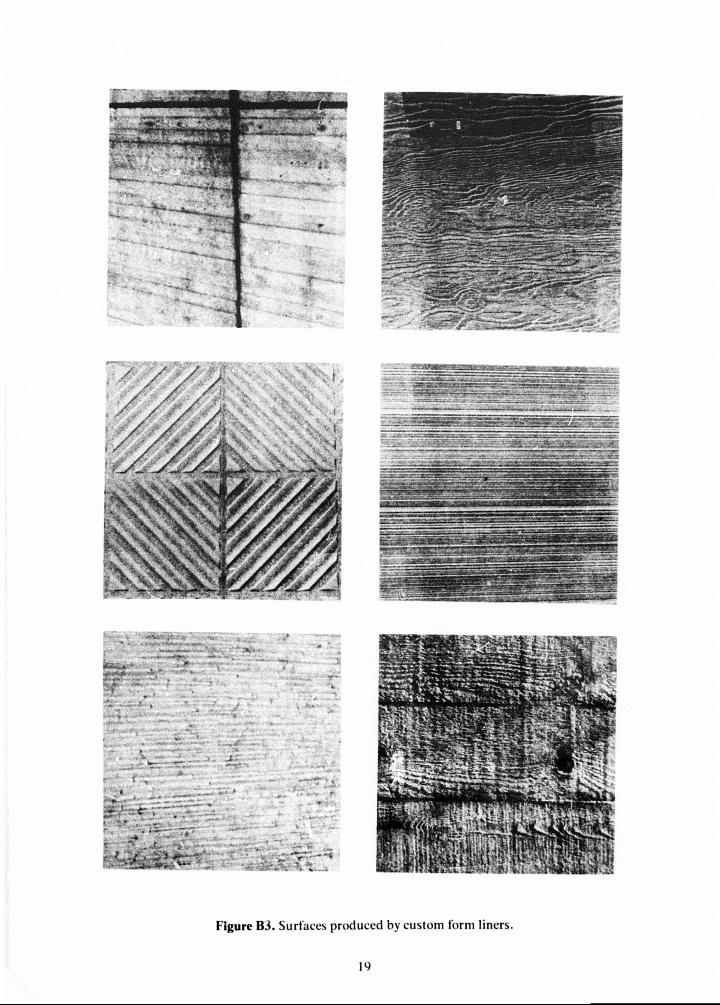
The concrete is cured as is conventional concrete After sufficient curing, the forms should be carefully removed. If tooling is applied to the textured surface to produce a special effect it should be done as scon as posaiole. Figure B2 illustrates examples of surface variations obtainable by mechanical finishing, and Figure 83 illustrates examples of special surfaces produced by custom form liners.
O COST FACTORS
The cost of form liners varies from $1.40/sq ft to $12.00/sq ft depending on the texture and the type of form liner material. This does not, however, pro- vide a true indication of the relative cost. In general, the form liners which are initially higher in cost may be cheaper on a life-cycle cost basis since they are fabricated from a higher quality material which may he reused several more times than the inexpensive liners.
4 LIMITATIONS
The primary limitation to the use of form liners is
!0

that proper use requires labor skilled in the place-ment of architectural concrete. Techniques used to place structural concrete are not always acceptable
lor architectural concrete placement. Also, as with all architectural concrete, the labor costs will be rela-tively high.
SltlATfO STRI AT ED BUCK
M A U CtUSHfO STONf AGSO BOABD GROOVED AND fcANDOM B';A
Figure Bl. Typical form liners and surfaces produced.
17

a. Rib surface after form removal b. Chiseled surface of concrete cast with liner rotated 45°
IIS 1^ \
11 i I
j* ^ I'M '*■
ii ill H^ 4 tnr 1^?
c. Light abrasive blast d. Hand tooled finish: chiseled
Figure B2. Examples of surface variations obtainable by mechanical finishing of surface produced by form liners.
18
1- •• •? :
Figure B3. Surfaces produced by custom form liners